

Page 1
W613 W614 PT-300 Planer Thicknesser. Page 1 of 4 5-05-2017
Slide in Guard
and lock in
place
EXTRA INSTRUCTIONS TO BE USED IN CONJUNCTION WITH THE FACTORY MANUAL.
Please note. Manual is suited to a machine with variable type fences and guarding so some of manual will not
suit the machine you purchased
Please carefully unpack joiner ##### # BLADES ARE SHARP # #####
Before use. Being careful of sharp blades in the centre of the top table as these will be currently unguarded
Your machine is factory set and generally ready to use with minimal pre-operation adjustments although some
adjustments may move during shipping or be different when machine is placed in its final position of use
Firstly remove all accessories off and around machine and put aside out of the way
Remove machine off the packing skid and position were needed.
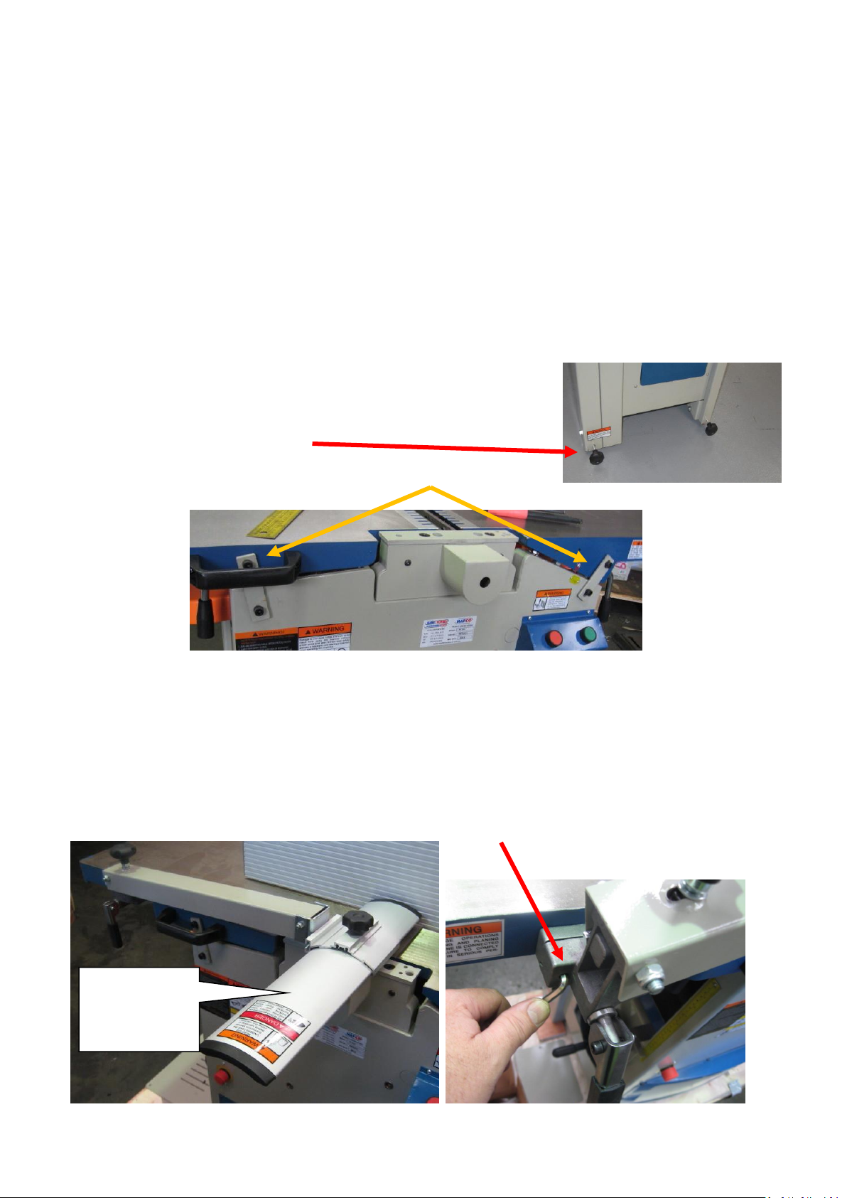
#1 Fit 2 x Wheel Locking knobs as shown at base of outfeed table end and
lock in place to hold machine fixed.
#2 Remove the 2 x shipping straps fitted to the tables
It is easier to remove the LH one by removing the Plastic Lifting handle first then re-installing it.
NB: The top screws have nuts on the end inside tunnel of machine and the lower screws are threaded into the
casting
#3 Clean the top of the table with an approved degreaser (WARNING Spindle Cutter blades are SHARP!)
# 4 Fit the Swinging spindle guard assemble to the front left hand side of the machine as shown
Use a 5mm Allen key provided through the holes in the bracket into encapsulated screws ready to fit
Page 2
W613 W614 PT-300 Planer Thicknesser. Page 2 of 4
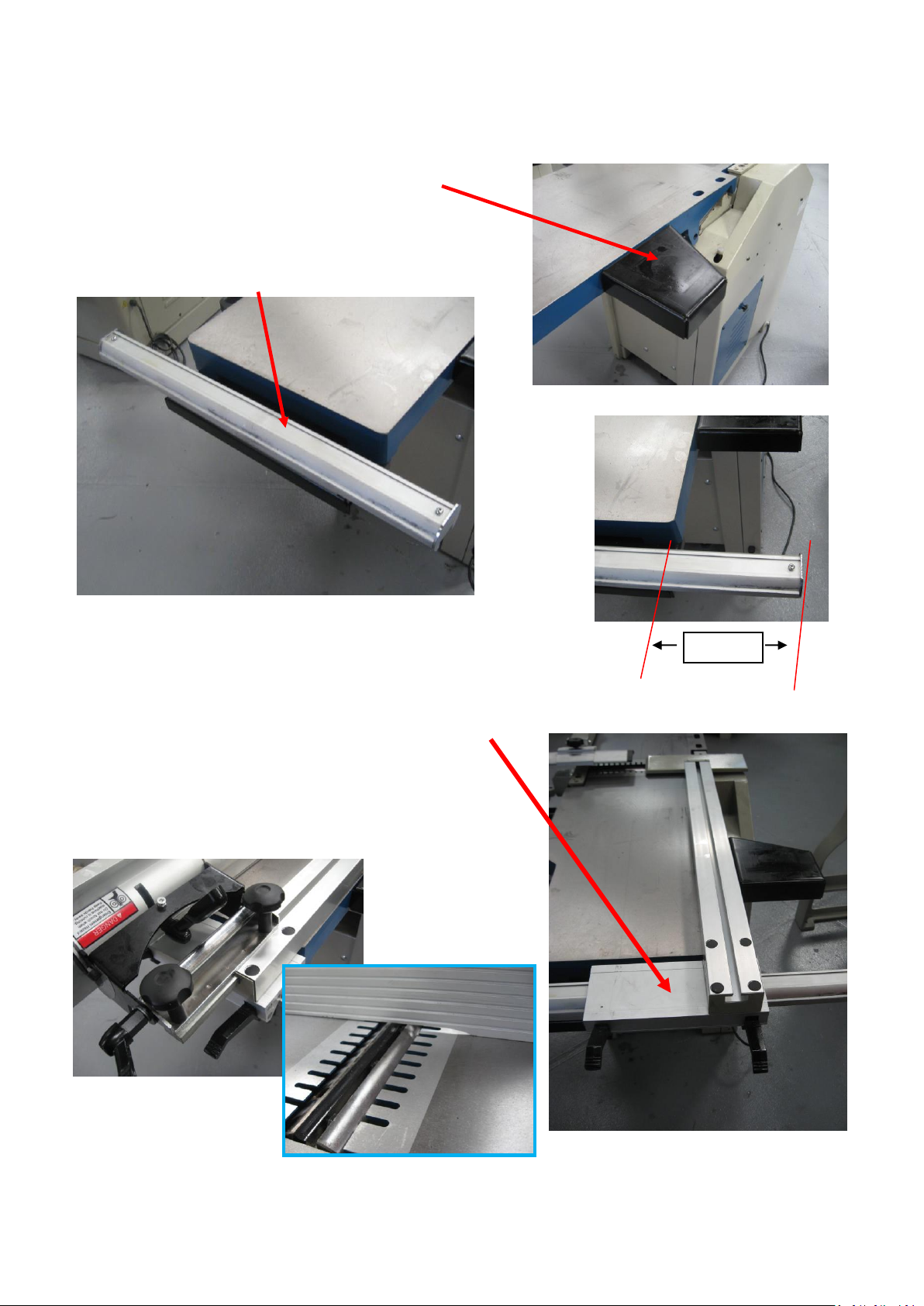
180mm
EXTRA INSTRUCTIONS TO BE USED IN CONJUNCTION WITH THE FACTORY MANUAL.
# 5 Fit the Rear LH support bracket as shown using 2 x M8 x
16mm Socket Head cap Screws supplied.
# 6 Fit the support for the Fence assemble using 2off
M8 x 20mm Socket Head cap Screws supplied to the underside
of the RH (infeed) table.
# 7 Undo the 2 screws holding the Fence rail to this support and slide
the Fence rail across to be out 180mm from side of table. Lock in place
# 8 Carefully fit the Fence support rail onto the Fence Rail and lock in place (2 front black levers)
# 9 With the 2 finger knobs loosened right off.
Slide the fence assemble onto the Fence Support
and along until cut-out in bottom of fence is 60mm from
centre of cutter head
Page 3
W613 W614 PT-300 Planer Thicknesser. Page 3 of 4
EXTRA INSTRUCTIONS TO BE USED IN CONJUNCTION WITH
THE FACTORY MANUAL.
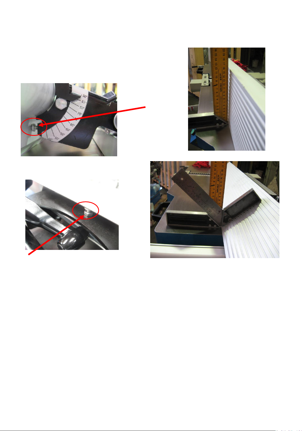
# 10 Check and adjust Fence angles if needed.
Tilt fence to 90 Degrees and put a Square or protractor up
against it.
If needed, adjust setting
screw and lock nut as
required
Tilt fence to 45 Degrees using 2 squares as
shown or a protractor up against it.
If needed, adjust setting screw and lock nut as
needed
#11 Checking/Adjusting top table Parallelism
As discussed in the factory manual this is set at factory, but because of the fine details it may need readjusting
after set up of machine. It is suggested to take a trial cut before doing this as finished product may be Ok
#12 When setting up for Planer mode, ensure for safety and Dust chip extraction, the thicknesser table is
wound all the way up to the 70mm mark before switching on
# 13 When adjusting height of Planer in feed table ensure table front table lock lever is loosened and Locking
bolt (socket head cap Screw) in end of rear adjustment shaft is loosened
Remember to lock both when height set. (See page 16 of manual Fig 16 for more detail)
#14 If after blade change height of Planer out feed table needs resetting. Ensure table front table lock lever is
loosened and Locking bolt (socket head cap Screw) in end of rear adjustment shaft is loosened
Remember to lock both when height set. (See page 16 of manual Fig 16 for more detail)
#15 Ensure the Thicknesser feed is always disengaged when not in use. Only engage when the planer is
switched on and disengage it before turning off.
Failing to do this can damaged the feed drive roller rubber coating, causing excessive wear and knocking noise.
#16 If fitting and using a Mortising Attachment (Hafco Code W615) Ensure Cutter guard is down at all times
and Thicknesser table is wound up to the 70mm mark for Safety.
Page 4
W613 W614 PT-300 Planer Thicknesser. Page 4 of 4
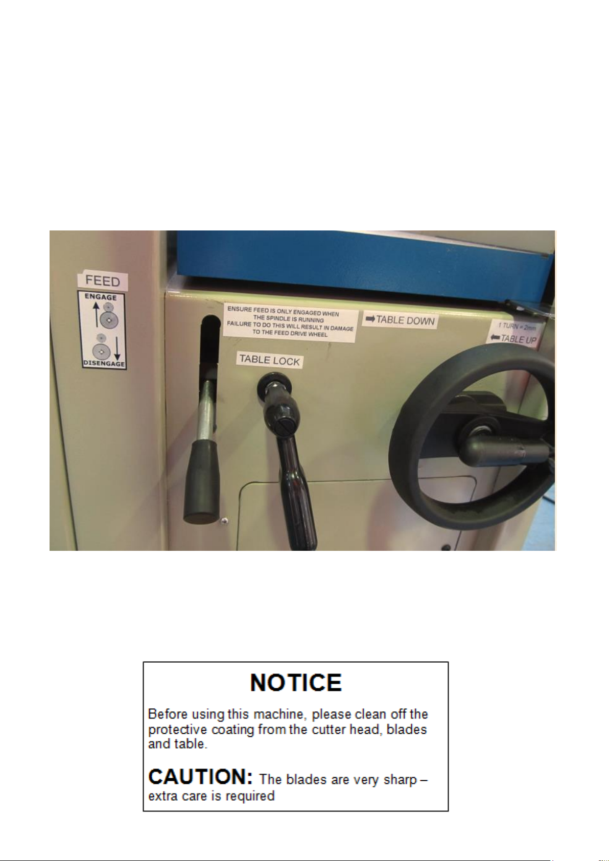
Please also note the following operational information
As per stickers for reference shown on below picture
# Thicknesser table
. 1 turn of Handwheel = 2mm movement
. Turning hand wheel anti clockwise moves table UP! (Makes thinner work piece!)
Ensure feed is only engaged when
the spindle is running.
Failure to do this will result in damage
to the feed drive wheel ”’
!
WARNING
Before using Morticer or top planer mode
Ensure for safety and efficient Dust chip extraction
That the lower Thicknesser table is wound up to the 70mm mark
and Planer guards are fitted before switching machine on.
 Loading...