

INSTRUCTION MANUAL
DIGITAL READOUT
Models
XH600-2, XH600-3
Order Code D5201, D5203
Edition no : XH600-1
datE of issuE : 03/2023
www.machineryhouse.co.nz

MACHINE DETAILS
INSTRUCTION MANUAL
XH600
MACHINE
MODEL NO.
Digital Readout
XH600
SERIAL NO.
DATE OF MANF.
distributEd by
www.machineryhouse.co.nz
NOTE:
This manual is only for your reference. At the time of the compiling of this manual ev-
ery effort to be exact with the instructions, specications, drawings, and photographs
of the machine was taken. Owing to the continuous improvement of the HAFCO
METALMASTER equipment, changes may be made at any time without obligation or
notice. Please ensure the local voltage is the same as listed on the specication plate
before operating any electric machine.
POWER SUPPLY
The PROTECTIVE EARTH CIRCUIT of the mains supply, MUST BE CONNECTED to the
protective earth terminal of the DRO through the supply cord.
The supply cord must be secured with cable ties to avoid from dropping into a hazardous
position, for example the oor or coolant tray, when disconnected from the DRO.
The supply cord must be routed away from moving parts, swarf, coolant or sources of heat.
MOUNTING
Select the location of the installation with due regard of safety and ease of operation. Keep the
DRO away of moving parts and coolant spray. To ensure correct operation of the DRO, make
sure that the DRO is correct grounding. The DRO may require grounding if different power
circuits are used. Grounding diagram can be found on page 52
www.machineryhouse.co.nz
2
INSTRUCTION MANUAL
C O N T E N T S:
XH600
Chapter 1 Identication
1.1 Front Panel 3 Axis........................ 4
Front Panel 2 Axis....................... 5
Rear Panel................................... 6
Identication Summary................ 7
1.2 Description Key Functions.......... 8
1.3 Interface....................................... 9
1.4 Coordinate System...................... 10
Chapter 2 Basic Operation
2.1 Power On..................................... 11
2.2 Zeroing The Axis.......................... 11
2.3 Inch / Metric Conversion............. 11
2.4 Enter a Dimension in an Axis....... 12
2.5 Calculating The Mid Point........... 12
2.6 Absolute/Incremental SDM Gps.. 13
2.7 Clear All SDM Datum................... 16
2.8 Lathe Function............................. 16
2.9 Vibration Filtering......................... 17
2.10 Entering/Exiting Display Settings 17
Chapter 3 SDM Coordinates
Chapter 6 Initial System Settings
6.1 Enter/Exit System Setup.............. 35
6.2 Setting DRO Type........................ 36
6.3 Setting DRO Positive Direction.... 36
6.4 Setting Error Correction Type...... 37
6.5 Toggle Between R/D Display....... 38
6.6 Setting Z Axis Dial........................ 40
6.7 Set the Scale Resolution.............. 40
6.8 Setting Input Mode in SDM Coor. 41
6.9 Setting Slope Mach. Parameter... 42
6.10 Toggle Linear Scale & Encoder.... 42
6.11 Step Mode for ARC Processing... 43
6.12 Angle Display Mode..................... 44
6.13 Angle Display Type...................... 45
6.14 Enable/Disable Error Signal......... 45
6.15 Setting Lathe Mode..................... 46
6.16 Set Display Brightness Grade...... 47
6.17 Setting Number of display Axes.. 47
6.18 Load Default Setup...................... 49
Chapter 7 Linearity Error Correction.... 50
Chapter 8 Troubleshooting.................. 51
3.1 Zeroing The Current Position....... 18
3.2 Preset Datum of SDM Coord....... 20
Chapter 4 Special Functions
4.1 Pitch Circle Hole Function........... 22
4.2 Bolt Hole Line Function............... 24
4.3 Arc Machining............................. 26
4.4 Slope Processing........................ 31
Chapter 5 Calculator Function
5.1 Enter and Exit Calculator.............. 33
5.2 Calculating Example.................... 33
5.3 Transferring Results to Axis........ 33
5.4 Transferring Display to Calculator. 34
Grounding Diagram............................. 52
www.machineryhouse.co.nz
3

INSTRUCTION MANUAL
Chaper 1 IDENTIFICATION
1.1 XH600-3 FRONT PANEL 3 AXIS
Become familiar with the names and locations of the controls and features shown below to
better understand the instructions when mentioned later in this manual.
XH600
ABS
mm
10
0.000
0.000
0.000
9
18
32
4
5
6
18
14
www.machineryhouse.co.nz
4
12
13151617
11
7

INSTRUCTION MANUAL
1.1 XH600-2 FRONT PANEL 2 AXIS
8
17
18
XH600
2
1
3
4
16
15
14
13
12
11
10
5
9
7
6
www.machineryhouse.co.nz
5

1.1 REAR PANEL
Main on / off switCH
powEr lEad soCKEt
INSTRUCTION MANUAL
sCalE ConnECtErs
grounding sCrEw
XH600
OPTIONAL ACCESSORIES
optional latHE Mounting Kit
Mounting braCKEts
optional Mill Mounting Kit
ordEr CodE d5206
ordEr CodE d5204
www.machineryhouse.co.nz
6

INSTRUCTION MANUAL
XH600
1.1 IDENTIFICATION SUMMARY
Become familiar with the names and locations of the controls and features shown on previous
pages to better understand the instructions if mentioned later in this manual.
1 Number, decimal point key
2 Calculator key
3 Reset key for calculator
4 Operation key (Add, sub, multiple and divide)
5 Key to conrm operation
6 Trigonometric function key
Four special function key (Simple R cutting function, Process a slope, Process
7
holes displayed equally on a circle, Process holes displayed equally on a line)
8 Select axis to operate
9 Zero selected axis
10 X/Y/Z Display window
11 Enter +/- sign
12 Display half value of an axis
13 Scroll up or down to select
Function shift key (in state of calculator, calculate anti-trigonometric function. In
14
display state of SDM coordinate, enter the state of input of SDM coordinate)
15 Toggle between ABS/INC coordinate
16 Toggle display unit between metric and inch
17 Indicates either metric or inch selected
18 Message window
www.machineryhouse.co.nz
7

INSTRUCTION MANUAL
1.2 DESCRIPTION OF KEY FUNCTIONS
KEY MARK KEY NAME FUNCTION
XH600
1
2
3
4
5
6 SDM Switch
7
8
9
10
11
X/Y/Z-Zero Zero selected axis.
Axis Selection Select axis to operate.
Inch/Metric Switch Toggle display unit between metric and inch
Center Finding Displays half the value of an axis.
ABS/INC Switch Toggle between ABS/INC coordinate.
Numeric Keys Enter number.
Decimal Point Enter decimal point.
+/- Sign Enter +/- sign.
Enter Conrm operation.
Clear all Cancel incorrect operation.
1. Calculate inverse trigonometric function in
calculating function.
2. Enter No. of SDM coordinate.
12
13
14
15
16
17
18 ARC Simple R cutting function
19
20
Calculator Enter or quit calculating state.
Trigonometric Function
Add: Subtract: Multi-
ple: Divide
Radical Sign Square root or square equations
BHC Process holes displayed equally on a circle.
BHL Process holes displayed equally on a line.
SLOPE Process a slope.
Item Selection Scroll up or down to select.
Calculate trigonometric or inverse trigonometric.
Operate adding: Subtracting: multiplying:
dividing.
www.machineryhouse.co.nz
8
INSTRUCTION MANUAL
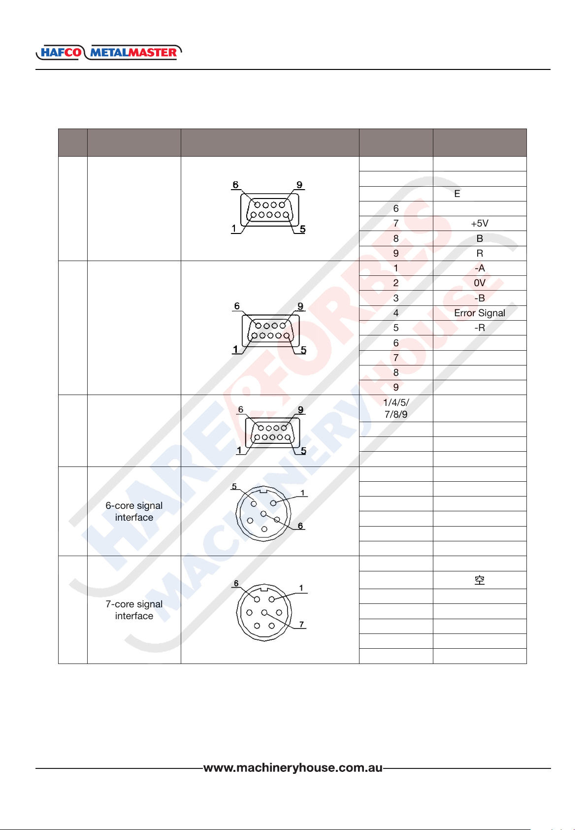
1.3 INTERFACE
No. Interface Type Schematic Diagram Pin Signal
1/3/5 Null
2 0V
1.
2.
3.
4.
5.
9-core TTL
9-core EIA-422-A
signal interface
EDM signal
6-core signal
7-core signal
Interface
interface
interface
interface
4 Error Signal
6 A
7 +5V
8 B
9 R
1 -A
2 0V
3 -B
4 Error Signal
5 -R
6 A
7 +5V
8 B
9 R
1/4/5/
7/8/9
2 Common Terminal
3 Normal Close
6 Normal Open
1 0V
2 A
3 B
4 R
5 +5V
6 PE Earth Wire
1 0V
2
3 A
4 B
5 +5V
6 R
7 PE Earth Wire
Null
XH600
www.machineryhouse.co.nz
9

INSTRUCTION MANUAL
XH600
1.4 COORDINATE SYSTEM
XH600 DRO is an instrument which can measure the position of the work piece when process-
ing. The coordinate system needs to be dened rst, for more efciency and accuracy.
On a vertical milling machine, the longitudinal travel of the table is parallel with the X axis, and
cross travel is parallel with the Y axis. Z is parallel to the spindle and is parallel to the up-anddown travel.
Origin is a point along the axis that reads zero.
Positive direction of an axis is set as the number increases as you move away from the origin.
The value of one point position is the distance relative to the origin of the coordinate.
For a work-piece as Figure A, the value of each point position is as Figure B when point O is the
origin of the coordinate.
Fig A
Fig B
www.machineryhouse.co.nz
10

INSTRUCTION MANUAL
Chapter 2. BASIC OPERATION
2.1 POWER ON
When the XH600 is Powered up it enters the normal display state, and memorizes the following
parameters.
A. The scales position when the power was switched off.
B. The mode selection when powered off (ABS/INC/SDM)
C. The Metric/Imperial mode when switched off.
2.2 ZEROING THE AXIS
The purpose of this function is to set the current position for that axis to ZERO
Example : Setting the current X axis position to ZERO
XH600
10,000
35.000
0000
SDm
2.3 INCH / METRIC CONVERSION
The purpose of this function is to switch the display between
Inch or Metric
EXaMplE 1. inCH to MEtriC
1,000
2.000
ABS
0000
Inch
X0
J
iNCH
MM
J
ð
ð
0,000
35.000
0000
SDm
25.400
50.800
0000
ABS
mm
ABS
mm
25.400
50.800
0000
EXaMplE 2. MEtriC to inCH
iNCH
MM
J
www.machineryhouse.co.nz
11
ð
1.000
2.000
0000
ABS
Inch

INSTRUCTION MANUAL
XH600
2.4 ENTER A DIMENSION IN AN AXIS
Function: Enter a value for an axis in normal display state.
NOTE: An Axis value can not be preset while the DRO is in other states (e.g. calculating function
or special function).
Press the and the X Axis will ash “0”, press the 1 and 2 and select “+” or “-” then press
“Enter”. If the value is incorrect press to cancel and input again.
X
AC
ABS
mm
0.000
50.800
0000
X
1
Ent
ABS
=
+ _
2
J
12.000
50.800
0000
mm
2.5 CALCULATING THE MID POINT
Function: Set the center of the work piece as datum by halving the displayed value.
To set the current X axis zero position at the centre of the work piece,
Step 1. Using an edge nder locate the edge at one end of the work
piece, then zero the X axis.
0,000
35.000
X0
J
ABS
mm
30.000
35.000
0000
Step 2. Using the edge nder locate the edge at the other end
of the work piece.
60,000
35.000
1
www.machineryhouse.co.nz
X
2
Step 3. Press then to half the
“X” axis display value.
12
1
2
X

INSTRUCTION MANUAL
XH600
2.6 ABSOLUTE / INCREMENTAL / 200 GROUP SDM
An ABSOLUTE movement moves to a measurement distance from the ZERO POINT.
An INCREMENTAL movement is a measurement based on the current position. An incremental
measurement does not take the parts zero point into consideration.
During machining operations, the operator can store the work piece datum ( ZERO position ) in
ABS coordinate, then switch to INC coordinate to continue machining operations
Then the operator is free then to zero the axes or preset any dimensions into any axis in INC coordinate for any relative position machining. The work piece datum (work piece ZERO position ) is
still kept in the ABS coordinate of the DRO.
Function: The XH600 series DRO has 3 display modes, absolute mode (ABS), incremental mode
(INC) and 200 group Second Data Memory (SDM) with the range of 000 to 199.
1. Zero point of the work-piece is set at the origin point of the ABS coordinate,
2 The relative distance between datum of ABS and SDM remains unchanged when ABS
datum is changed.
3. If one point in ABS is zeroed, the point in INC is zeroed automatically, yet if one point in INC
is zeroed, the point in ABS will remain unchanged.
Example: Currently in ABS display coordinate, to switch to INC display coordinate
ABS
mm
62.000
50.800
0000
ABS
iNC
Inc
42.000
50.800
0000
mm
J
A. Toggle between ABS/INC/SDM coordinates
These three display modes can be changed only in normal display state.
ABS to INC Press
INC to ABS Press
SDM to INC Press to enter ABS or INC, If in ABS: press again.
SDM to ABS Press to enter ABS or INC, If in INC: press again.
INC to SMD Press
ABS to SDM Press
ABS
iNC
ABS
iNC
ABS
iNC
ABS
iNC
SDM
S-N
SDM
S-N
ABS
iNC
ABS
iNC
www.machineryhouse.co.nz
13

INSTRUCTION MANUAL
II Set A New SDM Number In SDM Mode
Steps:
1. Enter SDM mode;
2. Press message window ashes, waiting for a new SMD
input number.
3. Enter a new number. for example, enter
4. Conrm new SDM number, then the message window stops
ashing and the SDM number is changed to 66.
III: Increase/Decrease The SDM Number.
Return the DRO to the normal display state with the SDM display
mode, press to decrease the SDM number by 1.
Press to increase the SDM number by 1.
q
SDM
S-N
q
6
6
XH600
SDm 13
mm
SDm 66
mm
Example 1: If the current SDM number is 77, and the message window displays “SDM 77”
Press then the message window will display “SDM 76” which means the current “SDM”
number is “76”.
q
SDm 77
mm
q
ð
SDm 76
mm
J
Example 2 :If the current SDM number is 77, and the message window displays “SDM 77”
Press then the message window will displays “SDM 78” which means the current SDM
number is 78.
q
SDm 77
mm
q
ð
SDm 78
mm
J
www.machineryhouse.co.nz
14

INSTRUCTION MANUAL
XH600
SETTING SDM COORDINATES FOR A WORKPIECE
If a work-piece as the gure at the bottom of the page is
to be machined, the datum plane is E, and the coordinates
can be set as the following steps below:
1. Return to the normal display state with ABS coordinate;
2. Move the machine table until the cutting tool is aligned
with plane E, then zero X axis.
3. Move the machine table until the cutting tool is aligned
with the plane D.
Change SDM number to SDM 000, and press to
X0
zero “X” axis.
Then the Number “SDM 000” coordinate’s datum is set
at plane D.
4. Move the machine table until the cutting tool is aligned
q
with plane C, press to change SDM to SDM 001,
and then press to zero X axis, and the SDM 001
X0
with the datum plane C is set.
ABS
mm
ABS
mm
SDm 000
mm
SDm 000
mm
0,000
-90,000
0,000
-35,000
0,000
5. Move the machine table until the cutting tool touches
the plane B, the DRO will display as the right.
6. Move the machine table until the cutting tool touches
the plane A, the DRO will display as the right.
SDm 001
mm
SDm 001
mm
SDm 001
mm
10,000
-35,000
www.machineryhouse.co.nz
15

INSTRUCTION MANUAL
XH600
2.7 CLEAR ALL SDM DATUM
Function: To clear all the Datum of the SDM settings 0 – 199. After clearing, the display the value
in the SDM coordinate will be equal to the value in the ABS coordinate.
Steps:
1. Return normal display state;
2. Press simultaneously for 10 times, and the message window will display “CLR SDM”
and ashes, which means it is now clearing. After a moment, the clearing will be completed
and “CLR OK” will be displayed in message window temporary and the DRO will return to
the normal display state.
.
.
cLR SDm
mm
ð
cLR OK
mm
JX10
2.8 LATHE FUNCTION
As per the image to the right, if two scales are in-
stalled in one axis, the position of the work-piece
should be the sum of these two values (X+Y) in
this direction. It is called lathe function.
A. Lathe mode 0: normal display (the lathe
function is disabled).
B. Lathe mode 1: X window value = the value of
X axis position + the value of Y axis position.
C. Lathe mode 2: X window value = the value
of X axis position + the value of Z axis
position.
D. Lathe mode 3: Y window value = the value of
Y axis position + the value of Z axis position.
Steps:
1. Set the lathe mode in initial system settings.
2. In normal display state press to enter lathe function.
3. In lathe state, press to exit the lathe function.
A. If in normal display state: the value of the position is as the right.
B. In lathe mode 3, the DRO will display as the following,
Y window display value = value of Y axis position + value of the
Z axis position
Z+Z1
sin
Z+Z1
sin
Y
X
10,000
20.000
30.000
ABS
mm
10,000
20.000
30.000
ABS
mm
www.machineryhouse.co.nz
16

INSTRUCTION MANUAL
XH600
2.9 VIBRATION FILTERING
Vibration ltering is especially useful for old and big machines in which the machine structure is
not rigid enough to get a stable display during machining or moving, or when machining in one
axis, the other axes may vibrate and hence the DRO display numbers are jumping around which
may cause confusions and uncomfortable position visualization to the operator.
If the operator cannot see the display value clearly. The XH600 series DRO provides vibration
ltering function to stabilize the digits display,
Steps:
1. Enter display value lter function In normal display state, press to enter the display
value lter function.
2. To exit the display value lter function, press again
COS
COS
2.10 Enter/Exit Setup Display Settings
Press to enter initial system setting after DRO
powers on for 1 second, then “SETUP” displays in the
message window.
=
Ent
q
Press or to select the item you want to change.
If you want to quit initial settings, press or
until “EXIT” appears in message window and press
q
q
q
=
Ent
Setup
mm
exIt
mm
www.machineryhouse.co.nz
17

INSTRUCTION MANUAL
XH600
Chapter 3. SDM COORDINATES - 200 GROUPS
The HAFCO METALMASTER XH-600 DRO has three display modes.
1. Absolute mode (ABS),
2. Incremental mode (INC) and
3. 200 groups second data memory (SDM 0—SDM199).
ABS datum of the work-piece is set at the beginning of the processing and the 200 group SDM
is set relative to ABS coordinate.
1. INC is independent of ABS, it won’t follow any change in ABS datum ( zero point ) .
However, all SDM coordinates are relative to ABS coordinate, all SDM positions are relative
to ABS’s zero, it will shift together with ABS zero position changes.
2. All SDM coordinate’s relative distance to ABS can be entered directly into the DRO using
the keypads. No need of any calculation or actual tool positioning in the machine.
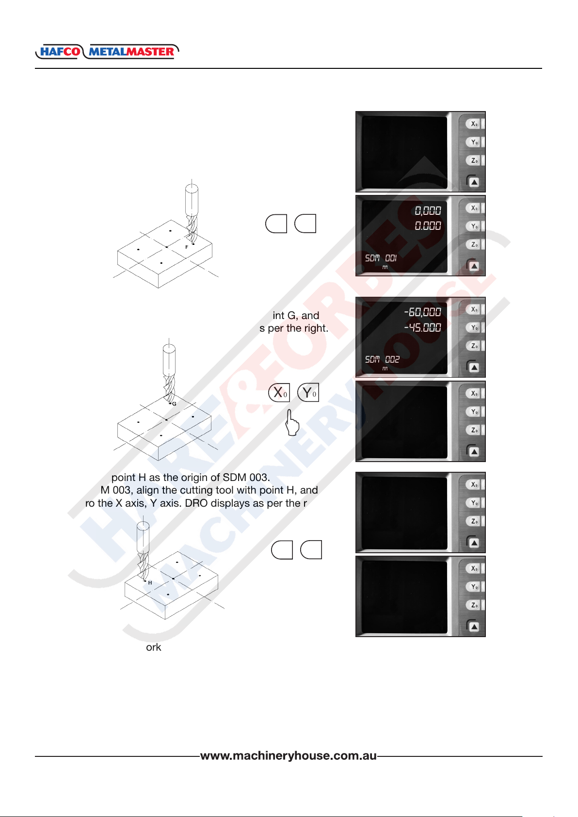
Example: The ABS datum is the center point O, the
point E, F, G, H needing processing are set as
a datum of SDM 000 — SDM 003.
Two ways to set SDM coordinates:
1. Zeroing at the current point;
2.` Presetting the datum of the SDM coordinate.
3.1 ZEROING AT THE CURRENT POINT
Set the center point of the work-piece as the origin of the
ABS, then align the lathe cutting tool with point E, F, G, H
by moving the machine table and zero them. It is the
processing position where the “0.00” appears in the X
window, Y window by moving the machine table whether
in ABS or in SDM coordinate.
Steps:
1. Set the center of rectangular point O as the datum of
ABS. Make line AB parallel with X axis: line AD parallel
with Y axis. When position lathe tool to point O
Zero X axis and Y axis in SDM 000.
Zero X axis and Y axis in SDM 001.
Zero X axis and Y axis in SDM 002.
Zero X axis and Y axis in SDM 003.
2. Set the point E as the datum of SDM 000.
SDM 000: align the cutting tool with point E and zero X
axis, and the Y axis. DRO displays as per the picture to
the right.
0,000
0.000
ABS
mm
-60,000
-45.000
SDm 000
mm
www.machineryhouse.co.nz
18
INSTRUCTION MANUAL
3.1 ZEROING AT THE CURRENT POINT Cont.
3. Set the point F as the datum of SDM 001.
In SDM 001 and align the cutting tool with point F,
then zero X axis, Y axis. DRO displays as per the right:
XH600
-60,000
-45.000
SDm 001
mm
X
Y
0
0
J
4. Set the point G as the origin of SDM 002.
In SDM 002, align the cutting tool with point G, and
zero the X axis, Y axis. DRO displays as per the right.
X
Y
0
0
J
5. Set the point H as the origin of SDM 003.
In SDM 003, align the cutting tool with point H, and
zero the X axis, Y axis. DRO displays as per the right.
X
Y
0
0
0,000
0.000
SDm 001
mm
-60,000
-45.000
SDm 002
mm
0,000
0.000
SDm 002
mm
-60,000
-45.000
SDm 003
mm
0,000
J
0.000
SDm 003
mm
6. Machine the work-piece according to the preset SDM coordinates.
7. Machine another work-piece according to the same blueprint. You only need to set the
center point as the datum of ABS. It is not necessary to set SDM coordinate again, as SDM
can be set automatically. Point E, F, G, and H are the zero points of SDM 000, SDM 001,
SDM 002, and SDM 003 respectively. Points can be machined when entering corresponding
SDM coordinate and where “0.000” appears in the screen by moving the machine table. This
function can save plenty of time where multiple pieces are to be machined
www.machineryhouse.co.nz
19
INSTRUCTION MANUAL
3.2 PRESET DATUM OF SDM COORDINATE
Compared with the way of zeroing at current point, another way, presetting SDM coordinate
datum, can set the zero point of the SDM more accurately and quickly without moving the
machine table.
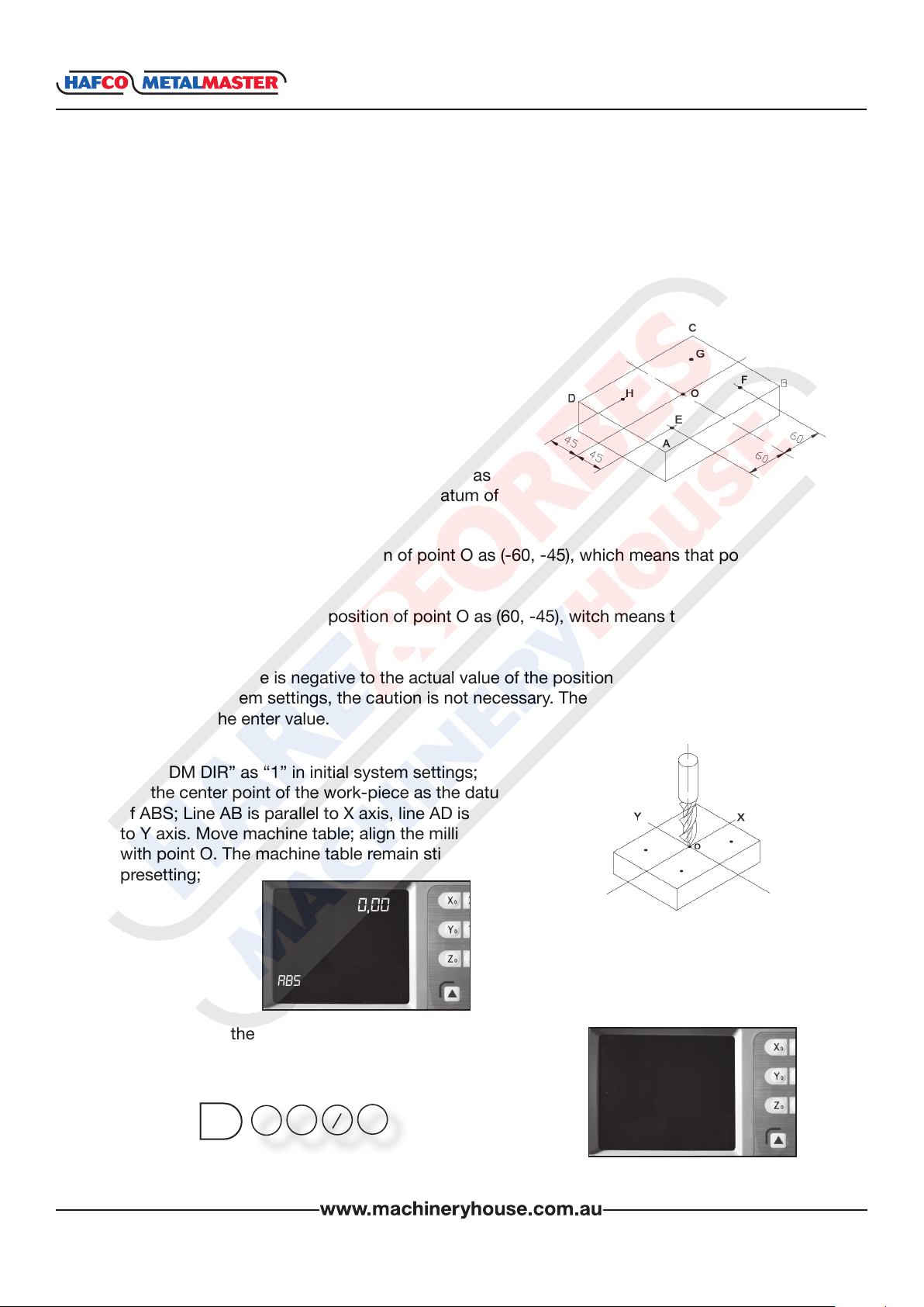
As the gure showed right, center point is the datum of
ABS, the position points E, F, G, H are (-60, -45),
(60, -45), (60, 45), (-60, 45) in the ABS coordinate.
A. Enter SDM 000 and preset the position of point O
as (60, 45), which means the point E is the datum of
SDM 000.
B. Enter SDM 001, preset the position of point O as
(-60, 45), which means the point F is the datum of
SDM 001;
XH600
C. Enter SDM 002 and set the position of point O as (-60, -45), which means that point G is the
the datum of SDM 002.
D. Enter SDM 003, preset the position of point O as (60, -45), witch means that point H is the
datum of SDM 003.
Note: The preset value is negative to the actual value of the position in ABS. If set “SDM DIR”
as “1” in initial system settings, the caution is not necessary. The value DRO accepts, is equal to
the negative of the enter value.
1. Set “SDM DIR” as “1” in initial system settings;
2. Set the center point of the work-piece as the datum
of ABS; Line AB is parallel to X axis, line AD is parallel
to Y axis. Move machine table; align the milling cutter
with point O. The machine table remain still while
presetting;
0,000
0.000
ABS
mm
3. Set point E as the datum of SDM 000.
Enter SDM 000.
The position of point E is (-60, -45), press.
=
+ _
0
X
6
Ent
J
www.machineryhouse.co.nz
60,000
45.000
SDm 000
mm
20
INSTRUCTION MANUAL
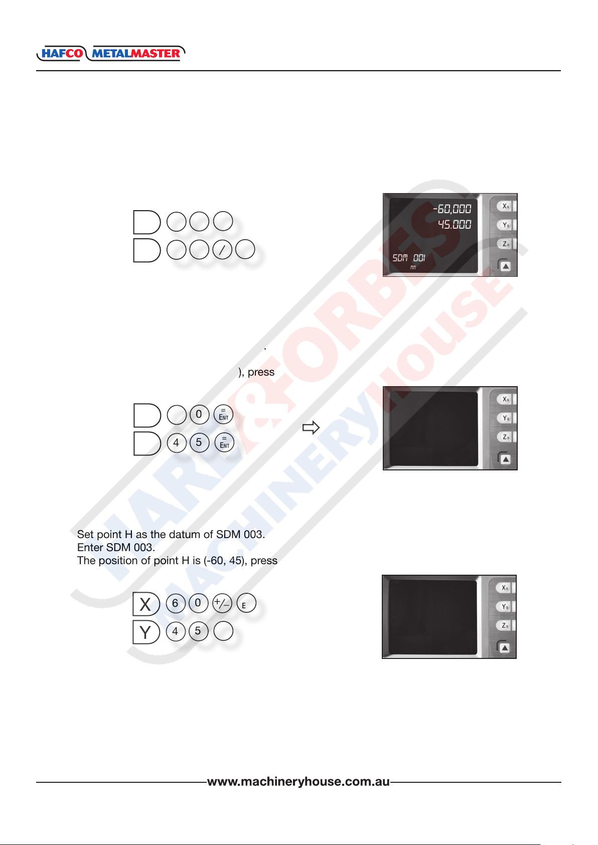
3.2 PRESET DATUM OF SDM COORDINATE Cont.
4. Set point F as the datum of SDM 001.
Enter SDM 001.
The position of point F is (60, -45), press
XH600
X
Y
5. Set point G as the datum of SDM 002.
Enter SDM 002.
The position of point G is (60, 45), press
X
Y
6
4
6
4
Ent
=
+ _
5
0
5
=
Ent
=
Ent
Ent
=
0
ð
ð
-60,000
45.000
SDm 001
mm
-60,000
-45.000
SDm 002
mm
6. Set point H as the datum of SDM 003.
Enter SDM 003.
The position of point H is (-60, 45), press
=
+ _
0
X
Y
6
5
4
Ent
=
Ent
www.machineryhouse.co.nz
21
ð
60,000
-45.000
SDm 003
mm
INSTRUCTION MANUAL
XH600
Chapter 4. SPECIAL FUNCTIONS
The Hafco Metalmaster XH600 series DRO has special functions as well as measuring and
positioning.
4.1 Pitch Circle Hole Function
4.2 Bolt Hole Line Function
4.3 Arc Machining
4.4 Slope Machining Function
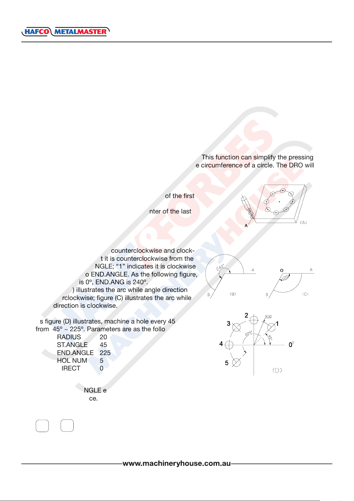
4.1 PITCH CIRCLE HOLE FUNCTION
Function description:
The XH600 series DRO has a Pitch Circle Hole Function. This function can simplify the pressing
of multiple holes which are attributed equally around the circumference of a circle. The DRO will
guide operator to enter the following parameters:
RADIUS: - Radius of circle
ST ANGLE: - Starting angle that the center of the rst
hole on the circle.
END.ANGLE:- Ending angle that the center of the last
hole on the circle.
HOLE NUM:- Number of Holes.
DIRECT:- Angle direction.
Angle has two directions: counterclockwise and clock-
wise. “0” indicates that it is counterclockwise from the
ST.ANGLE to END.ANGLE; “1” indicates it is clockwise
from ST.ANGLE to END.ANGLE. As the following gure,
the ST.ANGLE is 0º, END.ANG is 240º.
The gure (B) illustrates the arc while angle direction
is counterclockwise; gure (C) illustrates the arc while
angle direction is clockwise.
As gure (D) illustrates, machine a hole every 45 deg
from 45º ~ 225º. Parameters are as the following:
RADIUS 20
ST.ANGLE 45
END.ANGLE 225
HOL NUM 5
DIRECT 0
Note: If the ST.ANGLE equals the END.ANGLE, the holes are attributed equally around the
whole circumference.
The positions of the hole center are calculated automatically after input of all parameters. Press
q
or to choose the hole No. and move the machine table until the “0.000” appears in X
and Y windows. This is the position to process a hole.
q
www.machineryhouse.co.nz
22
INSTRUCTION MANUAL
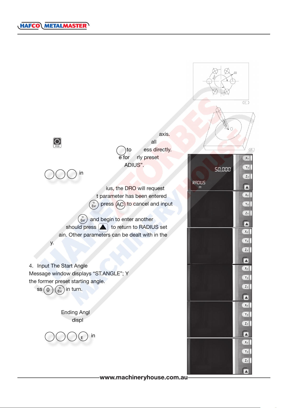
Example: Machine holes on circumference as the gure (E).
RADIUS 20MM
ST ANGLE 0°
END ANGLE 300°
HOL NUM 6
DIRECT 0
Steps:
1. Set the display unit to metric in normal state;
Move the machine table until the cutting tool is aligned
with the center of the circle, then zero X axis and Y axis.
2. Press to enter Pitch Circle Hole function. If all
q
=
Ent
AC
parameters have been set, press to process directly.
3. Input radius: Y window displays the formerly preset
radius; message window displays “RADIUS”.
Press in turn.
2
=
0
Ent
Note: If “0” is entered as the radius, the DRO will request
an input again. If an incorrect parameter has been entered
and you haven’t pressed press to cancel and input
=
Ent
again.
If you have pressed and begin to enter another
=
Ent
parameter, you should press to return to RADIUS set
and input again. Other parameters can be dealt with in the
same way.
XH600
50,000
RADIuS
mm
20
RADIuS
mm
20.000
4. Input The Start Angle
Message window displays “ST.ANGLE”; Y window displays
the former preset starting angle.
Press in turn.
=
0
Ent
5. Input The Ending Angle
Message window displays “END.ANGLE”; Y window displays
the former angle.
Press in turn
0
3
=
0
Ent
www.machineryhouse.co.nz
23
St AnGLe
mm
0
St AnGLe
mm
0
enDAnGLe
mm
300
enDAnGLe
mm
INSTRUCTION MANUAL
6. Input The Number Of Holes.
Message window displays “HOLE NUM”; Y window displays
the former number.
=
Press in turn.
Note: If “0” or “1” is entered as the number of holes, the
DRO will point out this mistake and requiure entering again.
7. Input angle direction.
Message window displays “DIRECT”, Y window displays the
former preset direction.
Press in turn.
0
Ent
=
0
Ent
XH600
6
hOLe num
mm
1
DIRect
mm
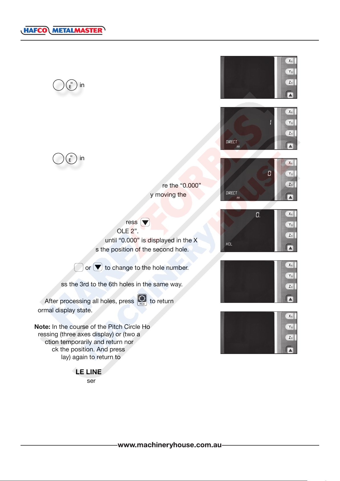
8. Message window displays “HOLE 1”.
It is the position of the rst hole to punch where the “0.000”
is displayed in X window and Y window by moving the
machine table.
9. After nishing the rst hole, press
q
Message window displays “HOLE 2”.
Move the machine table, until “0.000” is displayed in the X
and Y windows. This is the position of the second hole.
q
Note: Press or to change to the hole number.
10. Process the 3rd to the 6th holes in the same way.
11. After processing all holes, press to return to the
normal display state.
Note: In the course of the Pitch Circle Hole Function
pressing (three axes display) or (two axes) Pitch Circle Hole
Function temporarily and return normal display state in order
to check the position. And press (three axes display) or (two
axes display) again to return to the Pitch Circle Hole function.
q
0
DIRect
mm
0.000
0.000
hOLe 1
mm
0.000
0.000
hOLe 2
mm
0.000
0.000
hOLe 6
mm
4.2 BOLT HOLE LINE FUNCTION
Function: XH-600 series DRO provides BOLT HOLE LINE (BHL) function. This function can
simplify the processing multiple holes whose centers are attributed equally on one line. The
following parameters are needed to be entered.
LINE DIS Line distance (distance between the center of rst hole and the center of
the last hole)
LINE ANG Line angle (angle between the line and the positive X axis)
HOLE NUM Number of holes
www.machineryhouse.co.nz
24
INSTRUCTION MANUAL
4.2 BOLT HOLE LINE FUNCTION Cont.
XH600
The DRO will calculate the positions of the holes after the parameters have been entered or
q
press to select the number of the hole and move the machine table is displayed in the “X”
window. This will be position of the hole.
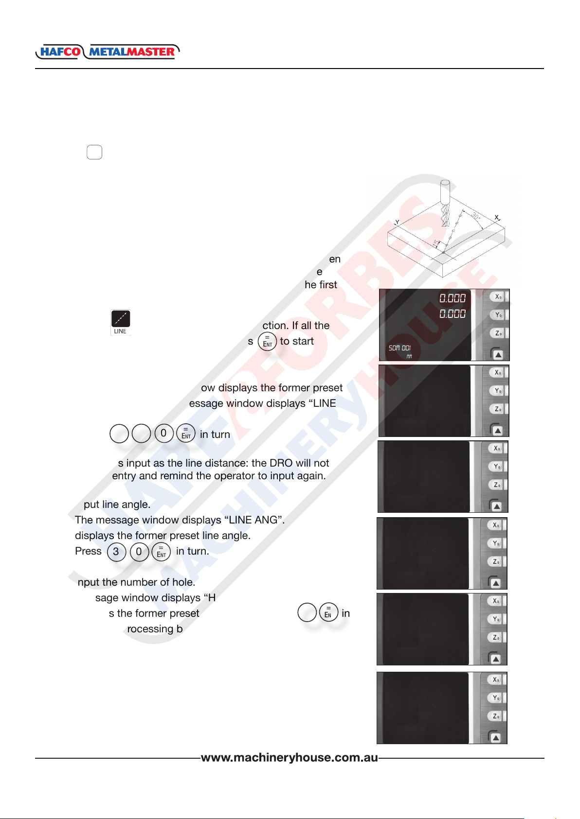
Example:
LINE DIS 150mm
LINE ANG 30°
HOLE NUM 6
Steps
1. Set display unit to metric and the shrinkage is not taken
into consideration. Move the machine table until the
machine tool is aligned with the center point of the rst
hole, and zero the X and Y axis.
0.000
0.000
2. Press to enter Bolt Hole Line function. If all the
parameters have been entered, press to start
processing directly.
=
Ent
SDm 001
mm
3. Input line distance. Y window displays the former preset
line distance, and the message window displays “LINE
DIS”.
=
0
5
Press in turn
1
Ent
LIne DIS
20.000
mm
Note: If “0” is input as the line distance: the DRO will not
accept the entry and remind the operator to input again.
150
4. Input line angle.
The message window displays “LINE ANG”. Y window
displays the former preset line angle.
Press in turn.
3
=
0
Ent
5. Input the number of hole.
Message window displays “HOLE NUM”, Y window
=
displays the former preset hole number. Press in
6
Ent
turn, and processing begins.
Note: If “0” or “1” is entered as a hole number, the DRO will
not accept the entry and remind the user to input again.
www.machineryhouse.co.nz
25
LIne DIS
mm
35000
LIne AnG
mm
30
LIne AnG
mm
10
hOLe num
mm

INSTRUCTION MANUAL
4.2 BOLT HOLE LINE FUNCTION Cont.
XH600
6. Message window displays “HOLE 1”.
Move the machine table until “0.000”appears in X window
and Y window, it is the center of the rst hole to punch.
7. After nishing the rst hole, press, and the message
q
window displays “HOLE 2”.
Move the machine table until “0.000” appears in X and Y
window, and then you can punch the second hole at this
point.
q
Note: Press or to move among the holes.
8. Process the holes 3rd – 6th in the same way.
9. Press to return to the normal display state when the
processing has nished.
q
6
hOLe num
mm
0.000
0.000
hOLe 1
mm
0.000
0.000
hOLe 2
mm
0.000
0.000
hOLe 6
mm
Note: In the course of Bolt Hole Line Function, you can press (three axes display) or (two axes
display) to leave this function temporarily and return normal display of X, Y, Z axis in order to
check the position which the DRO calculated. Then press (three axes display) or (two axes
display) again to return BHL function.
4.3 ARC MACHINING
This function is only for XH600-2, XH600-3.
It is waste of time to use a numerical control lathe to process an arc in a simple product or
small production run. This function makes it convenient to process an arc with a normal lathe.
Parameter “MAX CUT” is the arc length for each process. The smaller the MAX CUT, the more
smooth the arc plane and the longer processing time.
A. Process XZ, YZ plane
There are 8 modes as the following when processing arc in XZ or YZ plane:
www.machineryhouse.co.nz
26

4.3 ARC MACHINING Cont.
INSTRUCTION MANUAL
XH600
Milling cutter may be at-bottomed or arc-bottomed. If
at-bottomed, set the tool diameter as 0.
B. Process XY plane.
The DRO provides the 8 modes (shown at the top of the page)
in processing XY plane. The milling cutter is perpendicular to
the machine plane. The DRO has internal Arc machining and
external Arc machining for each type.
External T +TOOL.
Internal T - TOOL.
Set the tool radius according to the actual milling cutter when
process the XY plane.
TYPE 1 - 8 Mode of the Arc machining
* T+TOOL / T-TOOL Selection between T + TOOL / T - TOOL (This parameter is only for
XY plane)
RADIUS The radius of ARC that is to be processed
TOOL DIA Tool diameter
MAX CUT Feed step
Example 1:
Process an arc AB of 90° from point A to point B as the gure.
Parameters are as per the following,
Machine plane XY
ARC mode type 3
T + TOOL
RADIUS 20°
TOOL DIA 6mm
MAX CUT 0.5mm
www.machineryhouse.co.nz
27

INSTRUCTION MANUAL
XH600
4.3 ARC MACHINING Cont.
1. Set display unit is metric.
2. Move the machine table until the lathe tool is aligned with point
A, then zero X axis and Y axis.
3. Enter Arc machining state.
Press to enter Arc machining state,
If all parameters have been set, press to process directly.
4. Select machine plane,
Press to select XY.
=
X
Ent
X
Indicates XY Plane,
Note:
Indicates YZ Plane,
Indicates ZX Plane,
Y
Z
5. Select processing mode.
Message window displays “TYPE 1-8”, and Y window displays
the former processing mode.
=
Press in turn to select mode 3, and then enter ARC type.
3
Ent
6. Select T + Tool Mode.
Press to select the external Arc machining.
=
+
Ent
=
Ent
SDm 003
mm
SImR xZ
mm
SImR xY
mm
tYpe 1 - 8
mm
tYpe 1 - 8
mm
0.000
0.000
1
3
Note: indicates T + TOOL mode (external Arc machining).
Indicates T - TOOL mode (internal Arc machining).
+
-
7. Set Arc Radius.
Message window displays “RADIUS”, and Y window displays the
former arc radius.
Press in turn to enter the arc radius.
2
=
0
Ent
Note: If “0” as the arc radius is entered, the DRO will display an error
message and wait for another number entry.
t - tOOL
mm
t + tOOL
mm
RADIuS
mm
RADIuS
mm
RADIuS
mm
50.000
20
20
www.machineryhouse.co.nz
28

4.3 ARC MACHINING Cont.
INSTRUCTION MANUAL
XH600
8. Set Tool Diameter.
In the message window when “TOOL DIA” is displayed the Y
window displays the former preset diameter.
=
Press in turn to enter the tool diameter.
6
Ent
9. Set The Feed Step.
Message window displays “MAX CUT”.The Y window will display
the former feed step.
Press in turn to enter the feed step.
.
0
=
5
Ent
Note: If “0” is entered as the feed step, the DRO will not accept the
and wait for a correct entry.
10. Process ARC
Message window displays “POIN 1”. Process when the “0.000”
appears in X and Y window. Then when you have nished the rst
point, then Press to switch to the second point and repeat the
same step to move through the feed points. Process in this way
until the message window displays “POIN 74”. Pressing or
q
q
q
can select any processing point.
6
tOOL DIA
mm
10
mAx cut
mm
0.5
mAx cut
mm
0.000
0.000
pOInt 1
mm
0.000
0.000
pOIn 74
mm
11. Press to exit Arc machining after machining is over.
Note:
1. In the ARC process, pressing (three axes display) or (two axes
display) allows you to leave this function temporarily. To return to
normal display of X, Y, and Z axis in order or check the position the
DRO has calculated. Press (three axes display) or (two axes display)
to return to the ARC function.
q
2. Processing or can switch amongst the parameters in the
course of the presetting parameter.
Example 2:
Process the ARC EF as the gure from point E to point F.
Parameters are set as following.
Machine plane: XZ
TYPE: 4
RADIUS: Actual radius of the arc
TOOL DIA: 0 (at-bottomed tool)
MAX CUT: Preset as per the operators input
q
www.machineryhouse.co.nz
29

INSTRUCTION MANUAL
4.3 ARC MACHINING Cont.
Example 3:
Process the ARC DE as the gure from point D to point E.
Parameters are as per the following.
Machine plane: XZ
TYPE: 6
RADIUS: Actual radius of the arc
TOOL DIA: Actual value (actual tool)
MAX CUT: Preset as per the operators
imput
Example 4:
Process the ARC DE as the gure from point D to point E.
Parameters are as per the following.
Machine plane; YZ
TYPE: 7
RADIUS: Actual radius of the arc
TOOL DIA: Actual value (actual tool)
MAX CUT: Preset as per the operators
input
XH600
Note: For XH600-2, The DRO is not installed with Z-axis, please press or to simulate
position of the Z Axis. Press to simulate moving to the former process point, and emulate
moving to the former process point, and press to simulate moving to the next process.
Steps:
1. Set “STEP MODE” as “Z STEP” in setup mode, and set Z-axis dial (default value is 2.5mm).
2. Before machining, align the tool with the beginning point Z of R, zero Z axis.
3, In the machining process, the message window displays simulate height of Z axis, which
indicates simulate height of Z axis while machining.
As per gure to the right , while machining XZ plane,
X window displays the position of the X axis, X axis
is nished when displaying “0.000” in X window.
In the Y window, the former 2 numbers indicates the
number of the dial, and the following 5 numbers
indicate the scale number of the dial, which means that machining to this scale for the
current point.
While machining YZ plane, Y window displays position of Y axis, and when this window
displays “0.000”, this indicates the machining is nished in the Y direction.
In the X window, the former 2 numbers indicate the number of the dial, and the following
5 numbers indicate the scale number of the dial, which means that machining to this scale
for the current point.
q
q
0.000
12 1.000
31.000
mm
q
12 X 2.5+1=31
q
www.machineryhouse.co.nz
30

INSTRUCTION MANUAL
4.4 Slope Processing
This function is only for XH600-2, XH600-3.
Function:
This function can calculate the position of every processing
point automatically in processing slope. Only the following
parameters need to be inputted.
INCLE: Set machine plane XY, YZ or XZ plane
INCL.ANG: The inclination angle of the slope
MAX CUT: The slope length each time processing.
Note:
Z STEP and MAX.CUT are dened as the gure.
The DRO will calculate the position of each processing on
the slope automatically when all parameters have been input.
Press or to select the processing point and process
until “0.000” appears in the window.
q
q
XH600
Example 1.
Process the slope AB as the gure. The parameters are as
following.
INCLE: XZ
INCL.ANG: 45°
MAX.CUT: 12mm
Steps:
1. Set display unit to metric
Set the SLOP.MODE 1 in initial system settings.
Note: If the third parameter isn’t Z STEP, set the
SLOP.MODE 0.
Move the machine table until the lathe tool is aligned with
the starting point A, then zero X axis and Z axis.
Press , in normal display state.
X
0
Z
0
2. Press to enter the slop processing.
Press to start processing directly if all parameter
=
Ent
have been set.
0.000
35.000
SDm 001
mm
IncL xY
mm
3. Select machine plane.
Press in turn to select the ZX plane.
Z
=
Ent
www.machineryhouse.co.nz
31
IncL Zx
mm
INSTRUCTION MANUAL
4.4 SLOPE PROCESSING Cont.
XH600
Press indicates XY plane.
Press indicates YZ plane.
Press indicates ZX plane.
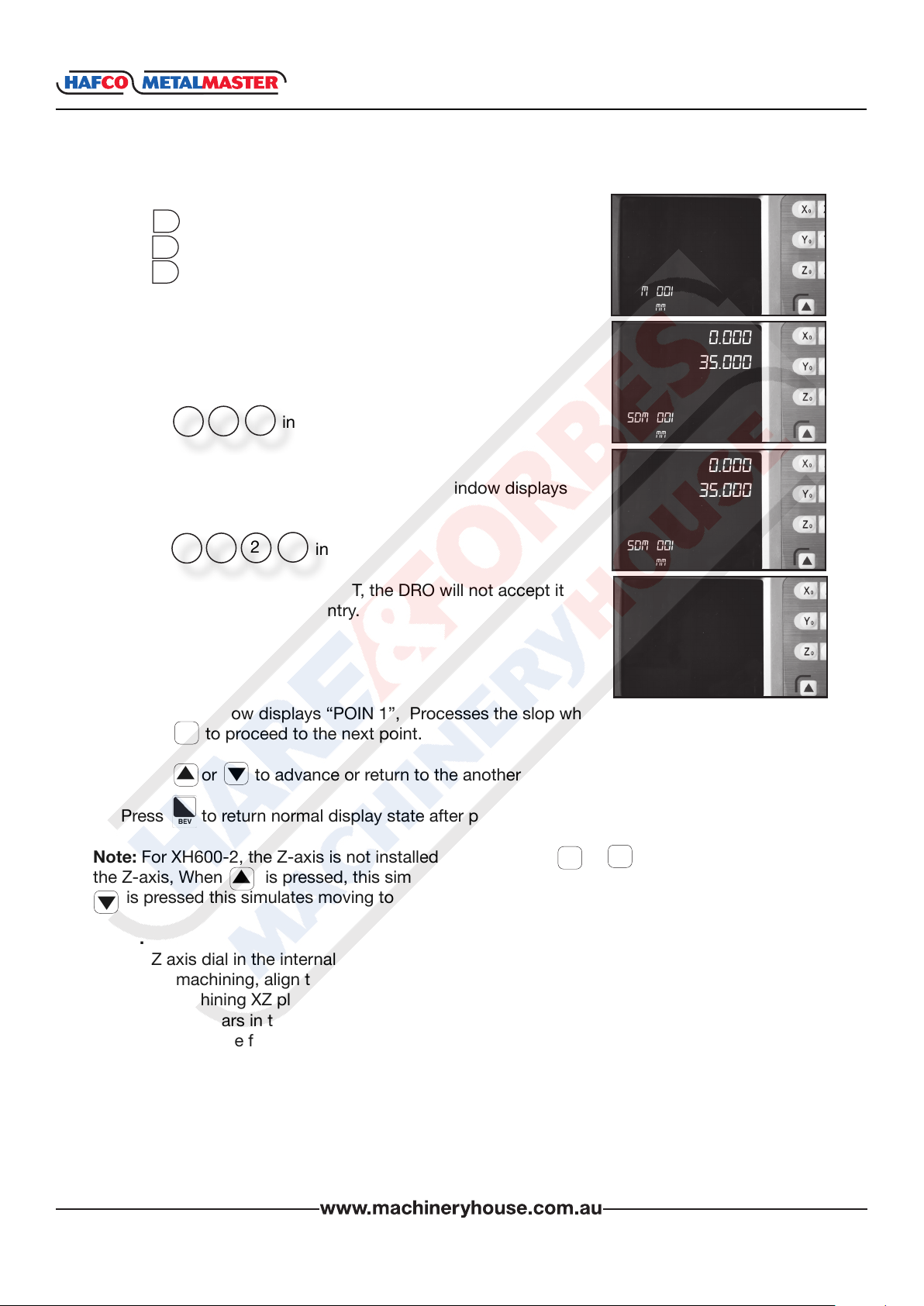
4. Enter INCL.ANG.
Message window displays “INCL ANG”. Y window displays
the former INCL.ANG.
Press in turn.
5. Enter MAX.CUT.
Message window displays “MAX CUT”. Y window displays
the former MAX.CUT.
Press in turn.
Note: If “0” is entered as MAX CUT, the DRO will not accept it
and will wait for another data entry.
X
Y
Z
=
5
4
1
Ent
.
=
2
Ent
0.000
35.000
SDm 001
mm
0.000
35.000
SDm 001
mm
0.000
35.000
SDm 001
mm
0.000
35.000
SDm 001
6. Processing.
Message window displays “POIN 1”, Processes the slop when the “0.000” appears, then
press to proceed to the next point.
q
mm
q
7. Press or to advance or return to the another point.
8. Press to return normal display state after processing is over.
q
q
Note: For XH600-2, the Z-axis is not installed, please press or to simulate position of
the Z-axis, When is pressed, this simulates moving to the former process point, and when
is pressed this simulates moving to the next process point.
q
Steps.
1. Set Z axis dial in the internal system setup;
2. Before machining, align the start point Z point with cutting tool, then set Z axis as “0.000”;
3. While machining XZ plane, X window displays position of the X axis. X axis is nished when
“0.000” appears in the X window, In the Y window, the former 2 number indicates number of
the dial, and the following 5 numbers indicate scale numbers of the dial, which means that
machining to this scale for current point.
While machining YZ plane, Y window display position of Y axis, and when this window dis
plays “0.000”, which indicates the machining is nished in Y direction; In X window, the
former 2 number indicates number of dial, and the following 5 number indicates scale
number of dial, which means that machining to this scale for current point.
q
q
www.machineryhouse.co.nz
32
INSTRUCTION MANUAL
Chapter 5. CALCULATOR FUNCTION
The XH600 provides an internal calculator for operations such as plus, minus, multiply and
divide, which is convenient for the operator when processing work piece according to the
drawing.
5.1 ENTER AND EXIT CALCULATOR FUNCTION
In normal display state: press to enter calculator function
In calculator state: press to exit calculator function.
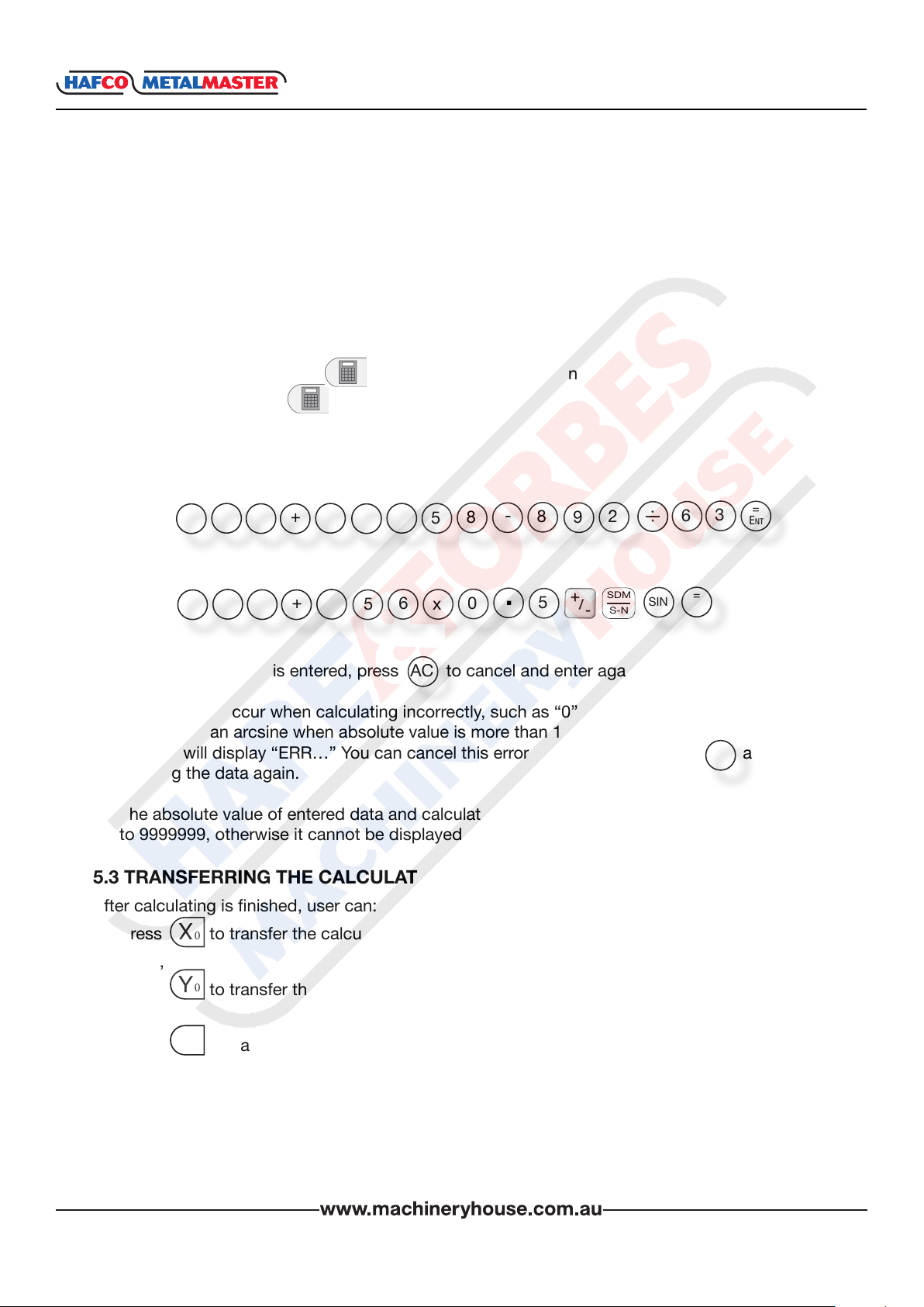
5.2 CALCULATING EXAMPLE
Example 1: 123 + 76 × 58 - 892 / 63
=
2
1
+
3
7
x
6
5
-
8
8
2
9
3
6
Ent
XH600
Example 2: 358 + 456 × sin -1(-0.5)
5
3
+
8
4
6
5
x
.
0
5
SDM
S-N
SIN
=
Ent
Note:
1. If the incorrect data is entered, press to cancel and enter again.
AC
2 An error may occur when calculating incorrectly, such as “0” being used as a divisor or
proceeding an arcsine when absolute value is more than 1. In this case, the message
window will display “ERR…” You can cancel this error message by pressing and
AC
entering the data again.
3. The absolute value of entered data and calculated result should be in the range of 0.000001
to 9999999, otherwise it cannot be displayed.
5.3 TRANSFERRING THE CALCULATED RESULTS TO SELECTED AXIS
After calculating is nished, user can:
Press to transfer the calculated result to the X axis. The X window will now display this
value,
Press to transfer the calculated result to the Y axis. The Y window will now display this
value,
Press to transfer the calculated result to the Z axis. The Z window will now display this
Y
Z
X
0
0
0
value.
Note: The calculated data can not be transfered if it is out of the displays range.
www.machineryhouse.co.nz
33
INSTRUCTION MANUAL
5.4 TRANSFERRING WINDOW DISPLAY VALUE TO CALCULATOR
While still in calculator mode:
Press to transfer the display value in X window to calculator.
Press to transfer the display value in Y window to calculator.
Press to transfer the display value in Z window to calculator.
X
Y
Z
XH600
www.machineryhouse.co.nz
34
INSTRUCTION MANUAL
Chapter 6. INITIAL SYSTEM SETTINGS
Function:
Set various parameters according to actual operation.
SEL TYPE Setting the number of linear scale
DIRECT Setting positive direction for the counter
COM TYPE Set the error correction type
R-D MODE Radius/Diameter Mode
Z DIAL Setting Z axis Dial
RESOLUTE Set the grating ruler’ s resolution
SDM DIR Setting the input mode of SDM
SLOP.MODE Setting the slope machining mode
AXIS.TYPE Setting the type of axis
STEP.MODE Select the step mode in ARC processing
ANGE.MODE Select the angle display mode
ANGE.TYPE Select the angle display type
ERROR Enable / Disable error message display
LATH.MODE Setting the lathe mode
DIS LEVE Set the brightness display degree
DISP BIT Set decimal point number
CLR ALL Clearing all customer setting and return default setting.
QUIT Exit internal system setting.
XH600
Note: Any entry that has been changed (except “CLR ALL”) will not been saved if you quit
“SETUP” (initial system settings) without selecting “QUIT” rst before exiting.
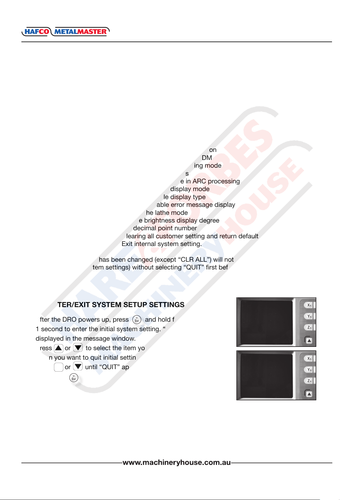
6.1 ENTER/EXIT SYSTEM SETUP SETTINGS
After the DRO powers up, press and hold for approximately
Ent
=
1 second to enter the initial system setting. “SETUP” will then be
displayed in the message window.
Press or to select the item you want to change.
When you want to quit initial settings.
Press or until “QUIT” appears in the message window and
then press
q
q
Ent
q
q
=
Setup
mm
QuIt
mm
www.machineryhouse.co.nz
35
INSTRUCTION MANUAL
XH600
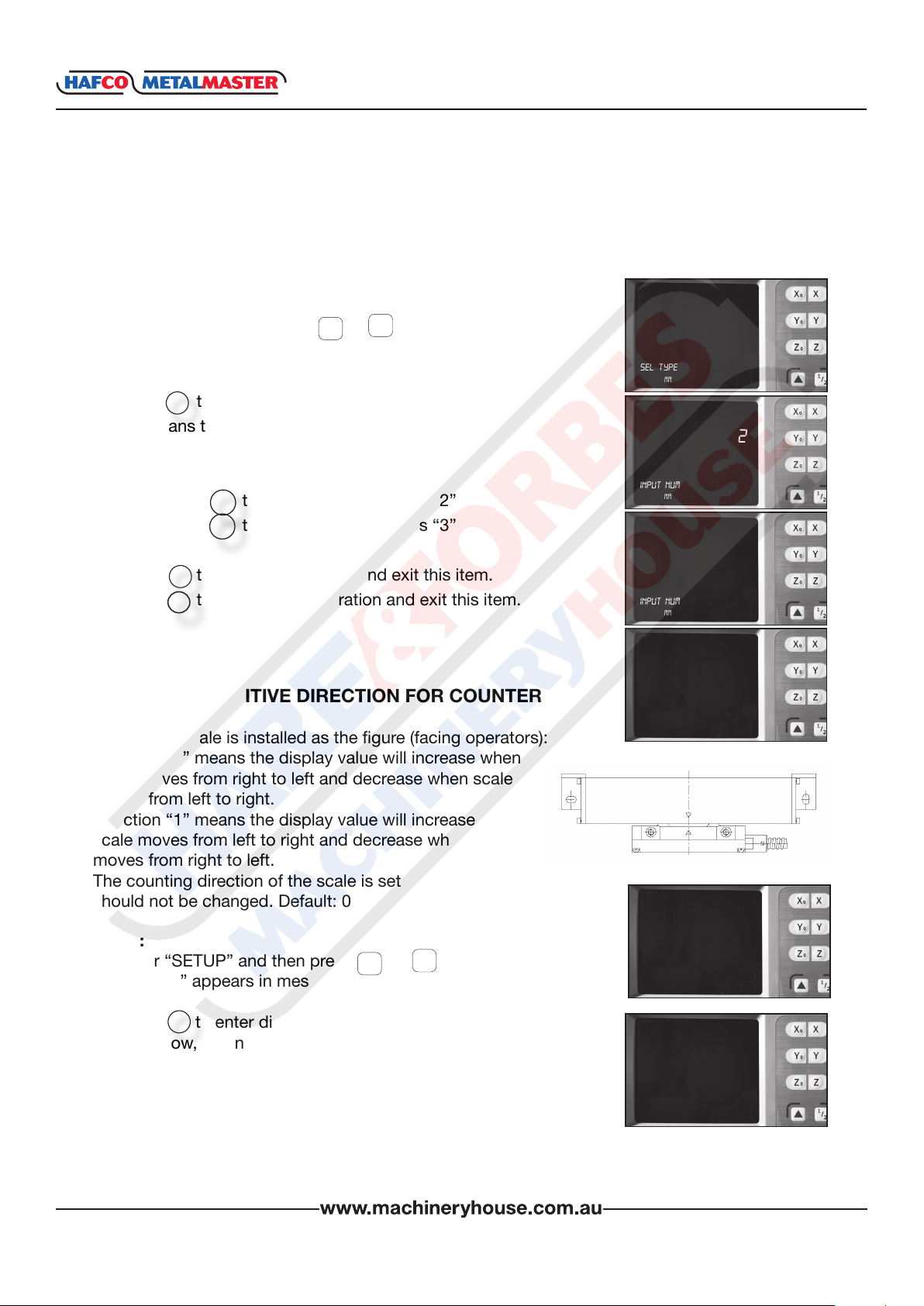
6.2 SETTING THE TYPE OF DRO
Because XH600 series DROs (two axes or three axes DRO) share the same software and their
functions have some differences, the DRO type must be set before use. CLR ALL has no effect
on type of DRO.
1. Enter “SETUP” and press or until “SEL TYPE”
appears in the message window.
2. Press then Y window displays “2” or “3”.
Ent
=
“2” means the DRO type is XH-600-2 two axis
“3” means the DRO type is XH-600-3 three axis.
3. If you press the “Y” window displays “2”
If you press the “Y” window displays “3”
4. Press to save the selection and exit this item.
Press to cancel your operation and exit this item.
AC
Ent
2
3
=
q
6.3 SETTING POSITIVE DIRECTION FOR COUNTER
If the linear scale is installed as the gure (facing operators):
Direction “0” means the display value will increase when
scale moves from right to left and decrease when scale
moves from left to right.
Direction “1” means the display value will increase when
scale moves from left to right and decrease when scale
moves from right to left.
The counting direction of the scale is set by the DRO and
should not be changed. Default: 0
q
SeL tYpe
mm
Input num
mm
Input num
mm
SeL tYpe
mm
2
3
Steps:
1. Enter “SETUP” and then press or until
q
q
DIRECT” appears in message window.
2. Press to enter direction setup.
Ent
=
X window, Y window and Z window display “0” or
“1” separately. “0” means the opposite counter
direction for “1” , in other words, “0” means A signal
exceed B signal and the counts increase during
counting. Vice versa.
Message window displays “SEL AXIS”, which means the
next step is to select axis.
www.machineryhouse.co.nz
36
DIRect
SeL AxIS
mm
mm
INSTRUCTION MANUAL
6.3 SETTING POSITIVE DIRECTION FOR COUNTER Cont.
XH600
3. Select axis
Press to change X axis counting direction.
Press to change Y axis counting direction.
Press to change Z axis counting direction.
4. Press to conrm your selection and exit.
Press to cancel your change and exit.
=
Ent
AC
X
Y
Z
SeL AxIS
DIRect
mm
mm
1
1
1
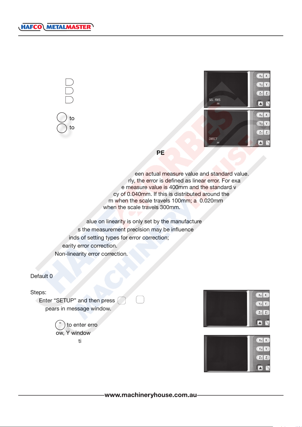
6.4 SETTING THE ERROR CORRECTION TYPE
Denition:
Linear error: There is always an error between actual measure value and standard value. If it is
distributed around the scale travel linearly, the error is dened as linear error. For example
the scale valid length is 400mm. If the measure value is 400mm and the standard value is
400.040mm: There is a discrepancy of 0.040mm. If this is distributed around the scale linearly,
there is a discrepancy of 0.10mm when the scale travels 100mm; a 0.020mm when the scale
travels 200mm, and 0.03mm when the scale travels 300mm.
Note: The correction value on linearity is only set by the manufacturer, and the user should not
modify randomly, as the measurement precision may be inuenced.
There are two kinds of setting types for error correction;
1. Linearity error correction.
2. Non-linearity error correction.
Default 0
Steps:
1. Enter “SETUP” and then press or until “COMP.TYPE”
q
q
appears in message window.
cOmptYpe
2. Press to enter error correction type setup.
=
Ent
mm
X window, Y window, and Z window displays the former linear
error compensation coefcient separately.
Message window displays “SEL AXIS” which indicates that the
next step is to select axis.
SeL AxIS
mm
0
0
0
www.machineryhouse.co.nz
37
INSTRUCTION MANUAL
6.4 SETTING THE ERROR CORRECTION TYPE Cont.
3. Select axis
Press to change X axis error correction type.
Press to change Y axis error correction type.
Press to change Z axis error correction type.
4. Press to conrm your selection and exit.
Press to cancel your change and exit.
X
Y
Z
=
Ent
AC
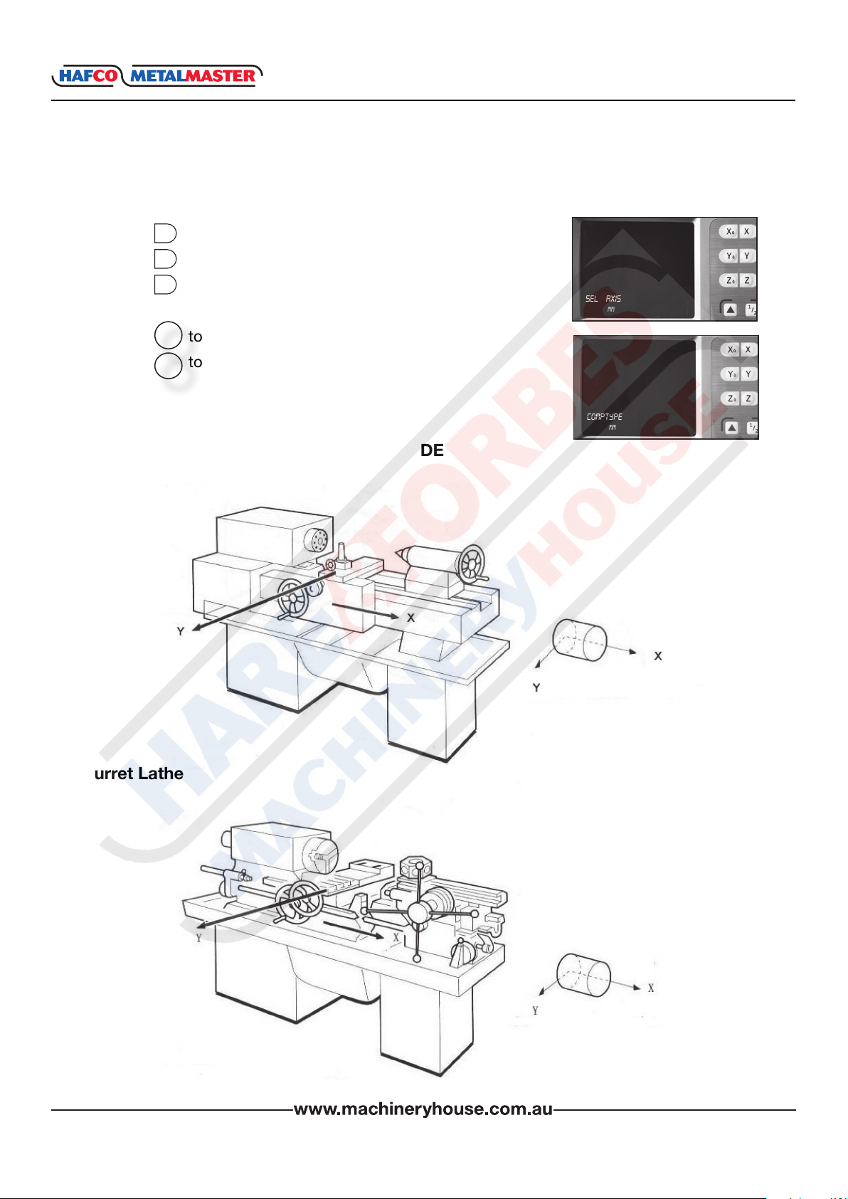
6.5 TOGGLE BETWEEN R/D DISPLAY MODE
Centre Lathe
SeL AxIS
mm
cOmptYpe
mm
XH600
1
1
1
Turret Lathe
www.machineryhouse.co.nz
38

INSTRUCTION MANUAL
XH600
6.5 TOGGLE BETWEEN R/D DISPLAY MODE Cont.
Face Plate Lathe
The machining process of a lathe is very different from the common vertical or horizontal
machines like milling, boring or drilling machines.
The display value is the distance between lathe tool and the workpiece origin. This display mode
is called “MODE R”. When turning a cylinder the given diameter measurement, is double the
distance between the lathe tool and the workpiece datum. To use the DRO with the display
showing the diameter, the DRO needs to be in “MODE D”.
The default mode of the DRO is “MODE R”.
Steps.
1. Enter “SETUP” and press or until the message
window displays “R-D MODE”.
q
q
2. Press
=
Ent
X window, Y window and Z window displays “0” or 1” separately.
“0” is mode R, which means the display value equals the actual
measurement. “1” is mode D where the display value equals
double the actual measurement.
Message window displays “SEL AXIS”, which indicates the next
step is to select the axis.
3. Select axis
In most cases the “Y” axis will be the axis that changes
Press to change the R/D mode of X axis.
Press to change the R/D mode of Y axis.
Press to change the R/D mode of Z axis.
4. Press to save the change and exit.
Press to cancel the change and exit.
X
Y
Z
=
Ent
AC
R-D mODe
mm
SeL AxIS
mm
SeL AxIS
mm
R-D mODe
mm
0
0
0
0
1
0
www.machineryhouse.co.nz
39
INSTRUCTION MANUAL
XH600
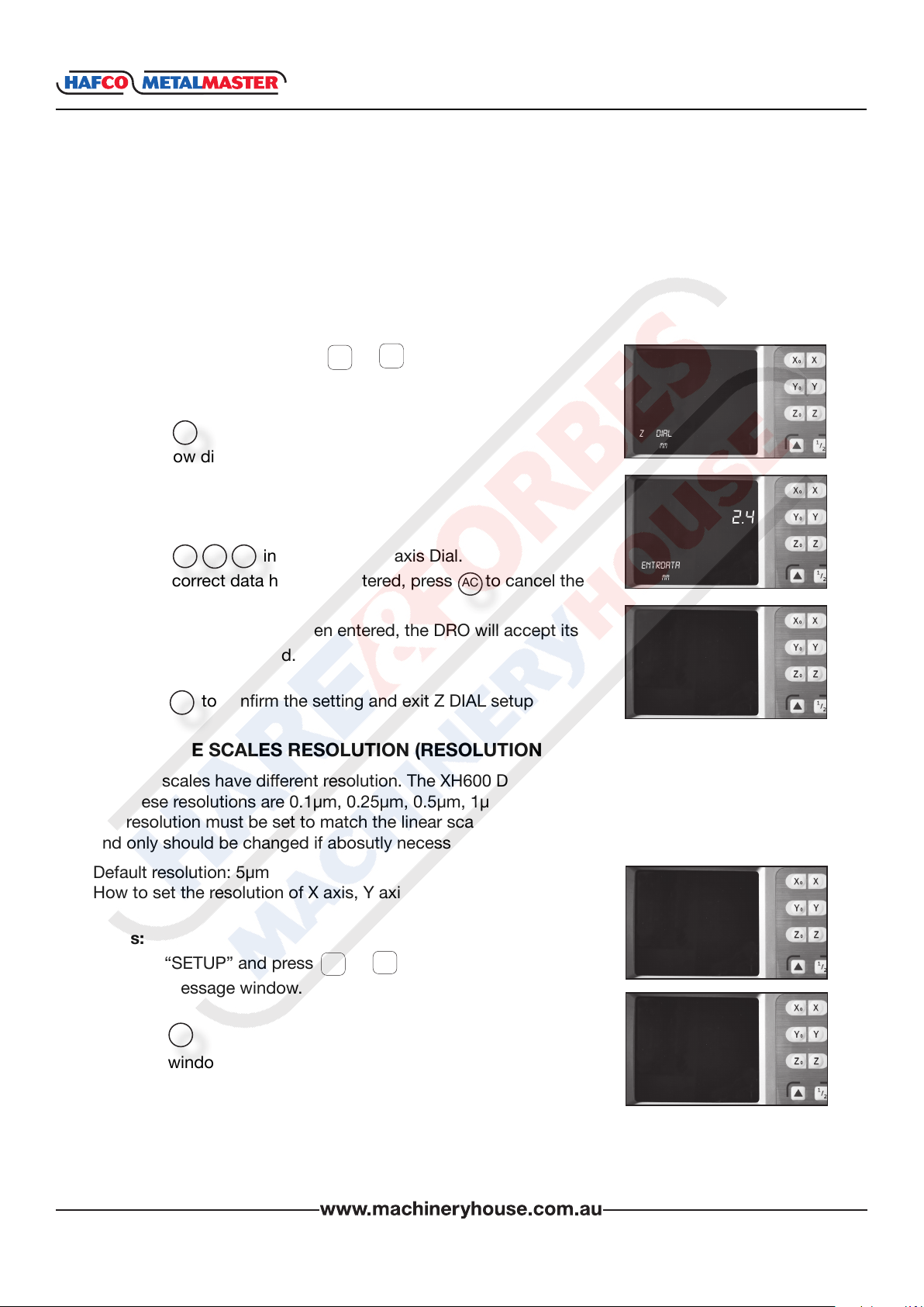
6.6 SETTING Z AXIS DIAL
The Z axis Dial should be set if the Z axis is emulated for XH600-2 and only X and the Y linear
scales have been install. Z axis Dial means the distance the Z axis travels when the screw is
rotated one revolution.
Default value: 2.5mm
How to set Z axis Dial to 2.4 mm.
q
1. Enter “SETUP”, then press or until the message
window displays “Z DIAL”.
q
2. Press
=
Ent
Z DIAL
mm
Y window displays the former Z axis Dial.
Message window displays “Z DIAL”.
2.4
3. Input the Z axis Dial.
Press in turn to input Z axis Dial.
If an incorrect data has been entered, press to cancel the
.
2
4
AC
entRDAtA
mm
entry and input again.
If a minus number has been entered, the DRO will accept its
absolute value instead.
4. Press to conrm the setting and exit Z DIAL setup
=
Ent
Z DIAL
mm
6.7 SET THE SCALES RESOLUTION (RESOLUTION)
Different scales have different resolution. The XH600 DRO can connect with 10 kinds of scales,
and these resolutions are 0.1µm, 0.25µm, 0.5µm, 1µm, 2µm, 5µm, 10µm, 20µm, 50µm, 100µm.
The resolution must be set to match the linear scale. This parameter is set by the manufacturer
and only should be changed if abosutly necessary.
Default resolution: 5µm
How to set the resolution of X axis, Y axis, Z axis to 1um.
Steps:
1. Enter “SETUP” and press or until “RESOLUTE” appears
q
q
in the message window.
2. Press
=
Ent
The X window, Y window and Z window will display the former
resolution of each axis separately. The message window displays
“SEL AXIS”, which indicates the next step is to select the axis.
www.machineryhouse.co.nz
40
ReSOLute
mm
SeL ReS
mm
5.00
5.00
5.00

INSTRUCTION MANUAL
6.7 SET THE SCALES RESOLUTION(RESOLUTION) Cont.
XH600
3. Select Axis
Press to change the resolution of the X axis, then the data
X
in the X window will ash.
Press to change the resolution of the Y axis, then the data
Y
in the Y window will ash.
Press to change the resolution of the Z axis, then the data
Z
in the Z window will ash.
q
4. Press or to scroll through 0.10, 0.20, 0.50, 1.00, 2.00,
5.00, 10.00, 20.00, 5 0.00, or 100.00.
Press to select “1.00” when it appears and return to
Ent
“SEL.RXIS” state.
Press to cancel your selection.
AC
5. Set the resolution of Y axis: Z axis by repeating step 3-4.
6. Press to exit the “RESOLUTE” setup.
q
=
SeL ReS
mm
SeL AxIS
mm
ReSOLute
mm
1.00
5.00
5.00
1.00
1.00
1.00
6.8 SETTING THE INPUT MODE IN SDM COORDINATE
The XH600 series DRO provides two data entry modes in trhe SDM coordinate:
MODE 0 (Normal entry mode): the data the DRO accepts equals the inputted data;
MODE 1 (Special entry mode): the data the DRO accepts equals the negative of the entered
number
Example: Set SDM mode 1.
q
1. Enter “SETUP”, then press or until the message
window displays “SDM DIR”.
2. Press
=
Ent
Y window displays the former SDM direction.
3. Press to set the SDM direction 1.
Note: Press to set the SDM direction 0.
1
0
q
SDm DIR
mm
SDm DIR
mm
0
1
SDm DIR
mm
www.machineryhouse.co.nz
41

INSTRUCTION MANUAL
6.8 SETTING THE INPUT MODE IN SDM COORDINATE Cont.
=
4. Press to conrm the setting and exit “SDM DIR”
Press to cancel the change and exit “SDM DIR”.
Ent
AC
SDm DIR
mm
6.9 SETTING THE SLOPE MACHINING PARAMETER
Parameters can be set in two ways for slope machining.
A. Set the steps of the second axis (Z STEP) in one plane, for XY plane.
set the steps of the Y axis, for YZ plane and set the steps of Z axis XZ plane set.
B. Set MAX CUT
Default setting: the step of the second axis (Z STEP).
Set the slope machining parameter MAX CUT. STEPS:
q
1. Enter “SETUP” and press or window displays
“SLOP.MODE”.
q
SLOp mODe
mm
2. Press
=
Ent
The Y window displays the former parameter mode.
Press to select MAX CUT parameter mode.
1
SLOp mODe
mm
0
XH600
Note. Press to select Z STEP parameter mode.
0
1
4. Press to save the change and exit this item.
Press to cancel your change and exit this item.
=
Ent
AC
SLOp mODe
mm
SLOp mODe
mm
6.10 TOGGLE BETWEEN LINEAR SCALE AND ROTARY ENCODER
Both linear scales or a rotary encoder can be installed in any axis. The linear scale is used to
measure distance; the rotary encoder is used to measure angles.
Default: linear scale.
Set rotary encoder in Z axis.
Steps:
q
1. Enter “SETUP” and press or until the message
window displays “AXIS.TYPE”;
q
AxIS tYpe
mm
www.machineryhouse.co.nz
42

INSTRUCTION MANUAL
6.10 TOGGLE BETWEEN LINEAR SCALE AND ROTARY ENCODER Cont.
XH600
2. Press
=
Ent
X, Y, Z windows will display the former type.
“LINEAR” means linear scale.
“ENCODE” means rotary encoder.
Message window displays “SEL AXIS”, which means the next
step is to select axis.
3. In this example the Z axis has been installed with a rotary
encoder.
Press until “ENCODE” is displayed in the Z window.
Note: Press to change the X axis.
Press to change the Y axis.
Press to change the Z axis.
4. Press to save the change and exit this item.
Z
Ent
X
Y
Z
=
SeL AxIS
mm
SeL AxIS
mm
LIneR
LIneR
LIneR
LIneR
LIneR
encODe
Press to cancel your change and exit this item.
AC
6.11 STEP MODE FOR ARC PROCESSING
In the ARC function, if the axis is not XY, you can setup the step mode. There are two modes.
Mode 0 is Z STEP mode and Mode 1 is MAX CUT mode.
Default setting: Z STEP
Example: setting the mode as the STEP mode.
Steps:
q
1. Enter “SETUP” and press or until the message
window displays “STEP.MODE”.
=
2. Press
Ent
The Y window displays the former setting. “0” means Z STEP.
“1” means MAX CUT.
The message window displays “SEL MODE”, which means
selecting the step mode for ARC next step.
q
Step mODe
mm
Step mODe
mm
0
www.machineryhouse.co.nz
43

INSTRUCTION MANUAL
6.11 STEP MODE FOR ARC PROCESSING Cont.
XH600
3. Setting the mode as STEP mode.
Press then the Y window displays the changed mode.
4. Press to save the change and exit this item.
Press to cancel your change and exit this item.
1
=
Ent
AC
Step mODe
mm
1
Step mODe
mm
6.12 ANGLE DISPLAY MODE
XH600 provides 3 angle display modes. In Mode 1, the angle is in the range of 0° to 360°.
In mode 2, the angle is in the range of -360°to 360°.
In mode 3, the angle is in the range of -180° to 180°.
Default mode: MODE 1.
Example: Setting the Angle display mode to mode 3.
Steps:
q
1. Enter “SETUP” and press or until the message
window displays “ANGL.MODE”.
q
AnGL mODe
mm
1
0 - 360
=
2. Press then the Y window displays the changed mode.
The message window will display “SEL MODE”, which means
Ent
SeL mODe
mm
the next step is to select the angle display mode.
3. Set the angle display mode as mode 3.
Press then the X window displays the changed mode.
3
The Y window will display the angle mode.
4. Press to save the change and exit “ANGL.MODE” setup.
Press to cancel your change and exit “ANGL.MODE” setup
=
Ent
AC
www.machineryhouse.co.nz
44
SeL mODe
mm
AnGL mODe
mm
3
-180 - 180

6.13 ANGLE DISPLAY TYPE
INSTRUCTION MANUAL
XH600
There are two angle display types for XH-600.
TYPE 0: indicate angle display is DD.
TYPE 1: indicate angle display is DMS.
Default value: TYPE 0°
Setting the angle display type to DMS.
Steps:
q
1. Enter “SETUP” and press or until the message
window displays “ANGL.TYPE”.
2. Press then the X window displays the former setup.
=
Ent
The Y window displays the former angle mode is DD°.
3. Set the angle display mode as MODE 1.
Press then the X window displays the changed mode.
1
The Y window will display the current mode as DMS.
q
AnGL tYpe
mm
SeL mODe
mm
SeL mODe
mm
0
360.00
1
35959.59
=
4. Press to save the change and exit “ANGL.TYPE” setup.
Press to cancel your change and exit “ANGL.TYPE” setup
Ent
AC
AnGL tYpe
mm
6.14 ENABLE / DISABLE ERROR SIGNAL
XH-600 serial DRO provides the function of checking whether the counting signal is normal or
not. It can display the ERROR information if some error occurs in counting the signal. The user
can enable or disable this function.
“0” means no error information will be displayed and the DRO continue to work when there is
some error with linear scale or encoder:
“1” means error information will be displayed when error occurs.
Default setting: 0 (disable display error message).
Example: Enable display ERROR message.
Steps:
q
1. Enter “SETUP” and press or until the message
window displays “ERROR”.
2. Press the Y window displays the former “0” setup.
=
Ent
q
eRROR
mm
0
www.machineryhouse.co.nz
45
eRROR
mm

INSTRUCTION MANUAL
6.14 ENABLE / DISABLE ERROR SIGNAL Cont.
XH600
3. Press to change it to enable error message.
Press to change to disable error message.
4. Press to save the change and exit “ERROR” setup.
Press to cancel your change and exit “ERROR” setup.
1
0
=
Ent
AC
eRROR
mm
eRROR
mm
6.15 SETTING LATHE MODE
Lathe mode 0: Disable lathe function;
Lathe mode 1: X window display value = the position of X axis + the position of Y axis;
Lathe mode 2: X window display value = the position of X axis + the position of Z axis;
Lathe mode 3: Y window display value = the position of Y axis + the position of Z axis;
Default mode: disable lathe mode.
Setting the lathe to mode 3.
Steps:
q
1. Enter “SETUP” and press or until the message
window displays “LATH.MODE”.
q
LAth mODe
mm
1
2. Press then the Y window displays the former setup.
=
Ent
3. Set the new lathe mode.
Press
Note: Press or 2 or or to change the lathe mode.
4. Press to save the change and exit “LATH.MODE” setup.
Press to cancel your change and exit “LATH.MODE” setup.
3
3 1 0
=
Ent
AC
www.machineryhouse.co.nz
46
nOne
mm
Z=Z+Z 1
mm
LAth mODe
mm
0
3

INSTRUCTION MANUAL
6.16 SET THE DISPLAY BRIGHTNESS GRADE
XH600
Function: The brightness displayed by the digital tube may be
regulated based on the environment on user’s site
environment, Grade 0~7 is divided totally.
Default grade: 5
Setting the display brightness grade 3.
Steps:
q
1. Enter “SETUP” and press or until the message
window displays “DSP.LEVE”.
2. Press then the Y window displays the former setup.
=
Ent
3. Press
Note: Press to 1 to change the brightness grade.
4. Press to save the change and exit “DSP.LEVE” setup.
Press to cancel your change and exit “DSP.LEVE” setup.
3
=
Ent
AC
7
q
DSp Leve
mm
LeD 5
mm
LeD 3
mm
DSp Leve
mm
6.17 SETTING THE NUMBER OF DISPLAY AXES
Function: The display is capable of setting the number of display axes on the coordinate
interface based on the users needs, from 1 to 6.
Default number of display axes: 3.
Setting the number of X display axis to 4.
Steps:
1. Enter “SETUP” and press or until the message
window displays “DSP.BITS”.
2. Press number of X display axis to 4, then the Y window
=
Ent
displays the former setup.
q
q
DSp BItS
mm
0.001
0.001
0.001
www.machineryhouse.co.nz
47
SeL AxIS
mm

INSTRUCTION MANUAL
6.17 SETTING THE NUMBER OF DISPLAY AXES
XH600
3. Select axis
Press to change the number of display X axis, then data in
X
X window ashes.
Press to change the number of display Y axis, then data in
Y
Y window ashes.
Press to change the number of display Z axis, then data in
Z
Z window ashes.
q
4. Press or to scroll through 0.1, 0.01, 0.001, 0.0001,
0.00001, 0.000001.
Press to select “0.0001” when it appears and return to
Ent
“SEL.AXIS” state. Press to cancel your selection.
5. Set the number of display Y axis: Z axis by repeating step 3-4.
6. Press to conrm the new set and exit.
Press to cancel the new set and exit.
Ent
AC
q
=
AC
=
SeL AxIS
mm
SeL AxIS
mm
DSp BItS
mm
0.0001
0.001
0.001
0.0001
0.001
0.001
6.18 LOAD DEFAULT SETUP
Function: Clear all data except the linear compensation and DRO type. DRO will load default
setup for all parameters. After loading default setup, user must search RI once to
enable resuming ABS datum function; otherwise to resume the datum by RI is unable.
Steps:
1. Enter “SETUP” and press or until the message
q
q
window displays “CLR.ALL”.
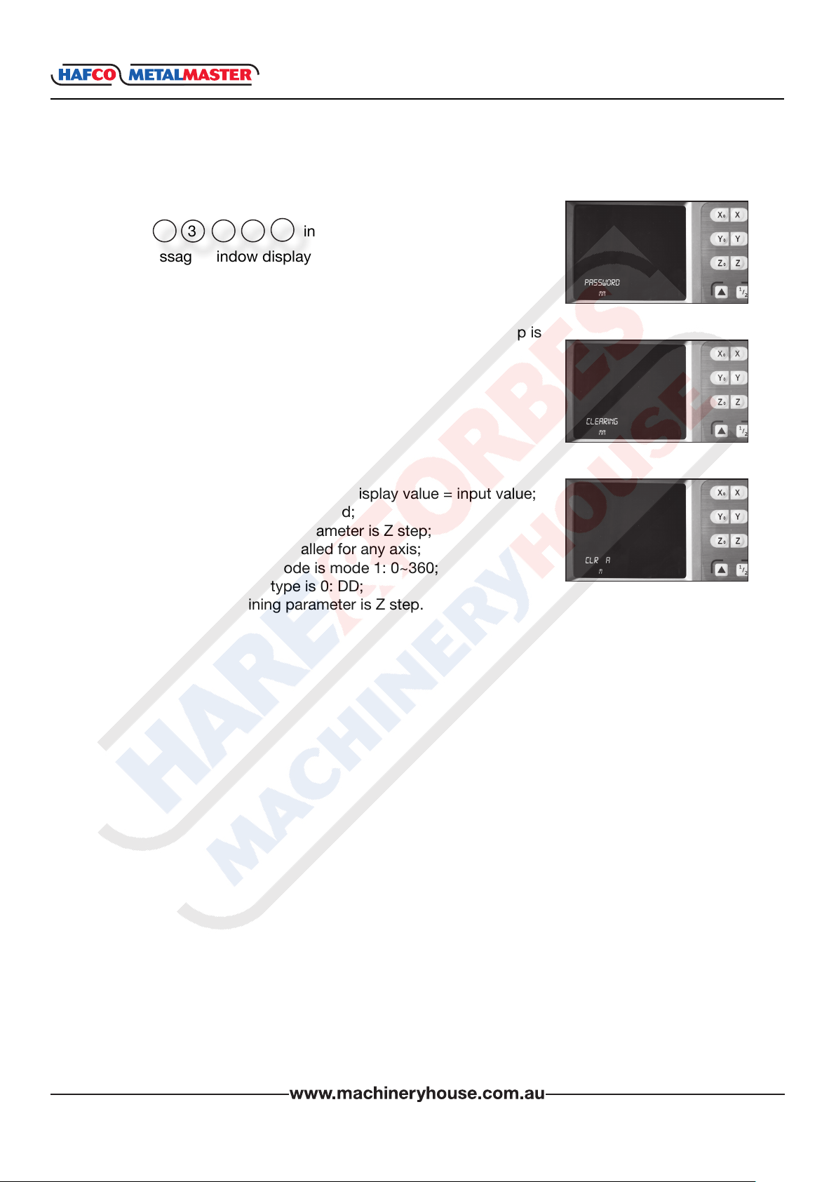
2. Press and message windows display “PASSWORD”
=
Ent
cLR ALL
mm
indicating the operator to input password. At this moment,
there are two selections:
____
A. Press to quit “CLR ALL”.
B. Enter the correct password to clear all parameters and load
default setup.
AC
pASSwORD
mm
www.machineryhouse.co.nz
48
INSTRUCTION MANUAL
6.18 LOAD DEFAULT SETUP Cont.
XH600
3. Input the password.
Press 3 in turn to load default value.
4 2 1
=
Ent
The message window displays “CLEARING”, which means the
data is clearing.
4. Return to the normal display state after loading default setup is
nished.
The default setup for all parameters is as follows.
w Counting direction is mode 0;
w The R/D is mode R ;
w Z DIAL = 2.5mm;
w Resolution = 5μm;
w Input mode in SDM as 0, display value = input value;
w Lathe function is disabled;
w Slope machining parameter is Z step;
w Linear scale is installed for any axis;
w Angle display mode is mode 1: 0~360;
w Angle display type is 0: DD;
w ARC machining parameter is Z step.
pASSwORD
mm
cLeARInG
mm
cLR ALL
mm
0000
www.machineryhouse.co.nz
49
INSTRUCTION MANUAL
XH600
Chapter 7 LINEARITY ERROR CORRECTION
Function:
There is a error between the grating ruler’s measuring value and standard value, if it is assumed
that the shape of two measuring curves within grating ruler’s travel range is consistent completely but isn’t coincide, which is called as linearity error.
Linearity correction: compensate the linearity error so as to enable that the display value is equal
to standard value.
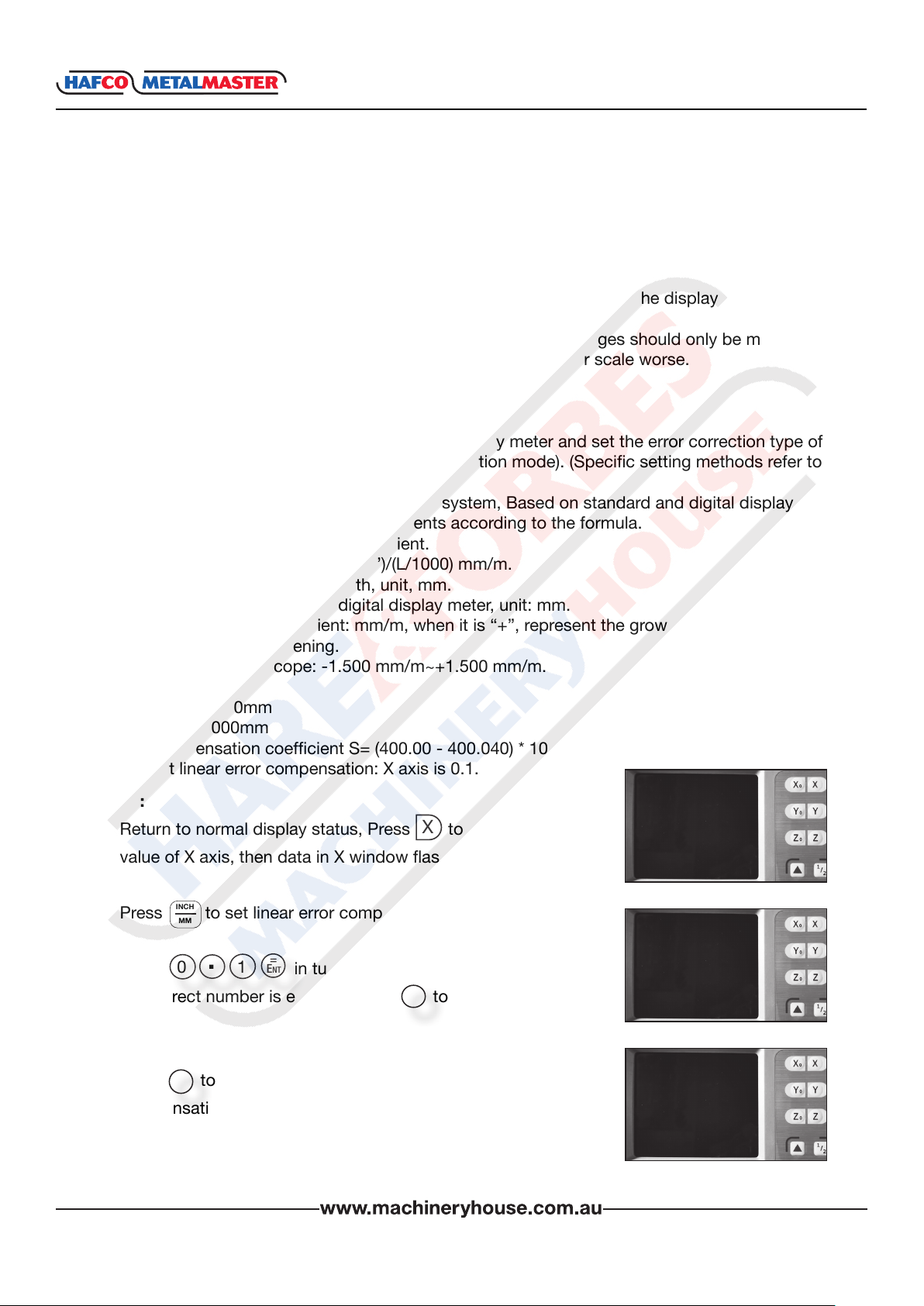
NOTES: The linear compensation is set by the manufacturer. Changes should only be made
after careful consideration as it could make the accuracy of linear scale worse.
Default coefcient: 0
Step 1: Enter into the parameters inside digital display meter and set the error correction type of
corresponding axle is 0 (linearity compensation mode). (Specic setting methods refer to
Chapter 6.4)
Step 2: Input the linearity error compensation system, Based on standard and digital display
value, calculate the correct coefcients according to the formula.
The calculation of compensation coefcient.
Correction coefcient: S =(L-L’)/(L/1000) mm/m.
L---actually-measured length, unit, mm.
L’---display value on the digital display meter, unit: mm.
S--- correction coefcient: mm/m, when it is “+”, represent the growth; when it is “-”,
represent the shortening.
Compensation scope: -1.500 mm/m~+1.500 mm/m.
Example:
L’ = 400.040mm
L = 400.000mm
Compensation coefcient S= (400.00 - 400.040) * 1000 / 400 = 0.1 Unit: mm/m.
Set linear error compensation: X axis is 0.1.
0
Steps:
1. Return to normal display status, Press to preset display
X
value of X axis, then data in X window ashes.
ABS
mm
0.000
0.000
2. Press to set linear error compensation.
3. Press in turn.
If incorrect number is entered, press to cancel and enter
INCH
MM
0
.
=
1
Ent
AC
again.
4. Press to conrm your setting and exit the linear error
=
Ent
compensation setup.
www.machineryhouse.co.nz
50
cOmpen x
mm
cOmpen x
mm
0
0.000
0.000
0.1
0.000
0.000
INSTRUCTION MANUAL
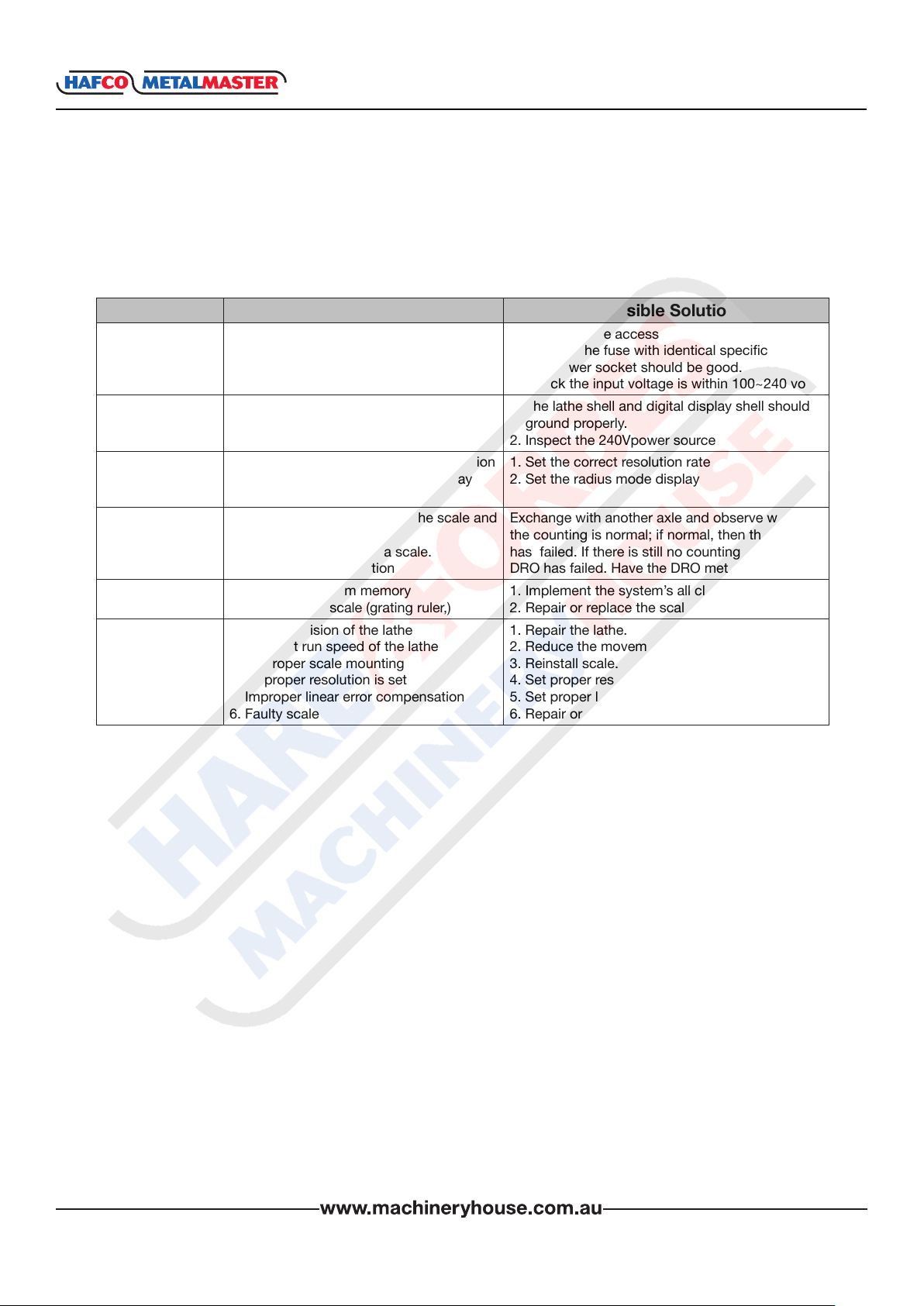
Chapter 8 TROUBLE SHOOTING
Review the troubleshooting and procedures in this section if a problem develops with your
equipment. If additional help with a procedure is required, then contact you distributor.
Note: Make sure you have the model number, before calling.
Symptoms Possible Cause Possible Solution
No display
DRO Cover is
charged
Display value is
double
No counting
Display value is in
disorder
Incorrect
counting
1. Power source failure
2. Damage of fuse
3. Poor 220V power source wiring
4. Inappropriate power voltage.
1. Improper grounding between lathe and
digital display.
2. Leakage of Electricity
1. Improper setting of the scales resolution
2. Some axle is set as diameter display
mode
1. Improper contact between the scale and
the reader head.
2. No signal output from a scale.
3. Failed counting function
1: Disorderly system memory
2. Failure of the scale (grating ruler,)
1. Poor precision of the lathe
2. Too fast run speed of the lathe
3. Improper scale mounting
4. Improper resolution is set
5. Improper linear error compensation
6. Faulty scale
1. Power source access
2. Replace the fuse with identical specication
3. The power socket should be good.
4. Check the input voltage is within 100~240 volts
1. The lathe shell and digital display shell should
ground properly.
2. Inspect the 240Vpower source
1. Set the correct resolution rate
2. Set the radius mode display
Exchange with another axle and observe whether
the counting is normal; if normal, then the scale
has failed. If there is still no counting then the
DRO has failed. Have the DRO meter repaired.
1. Implement the system’s all clear.
2. Repair or replace the scale (grating ruler)
1. Repair the lathe.
2. Reduce the movement speed of the scale.
3. Reinstall scale.
4. Set proper resolution.
5. Set proper linear error compensation.
6. Repair or exchange linear scale.
XH600
www.machineryhouse.co.nz
51
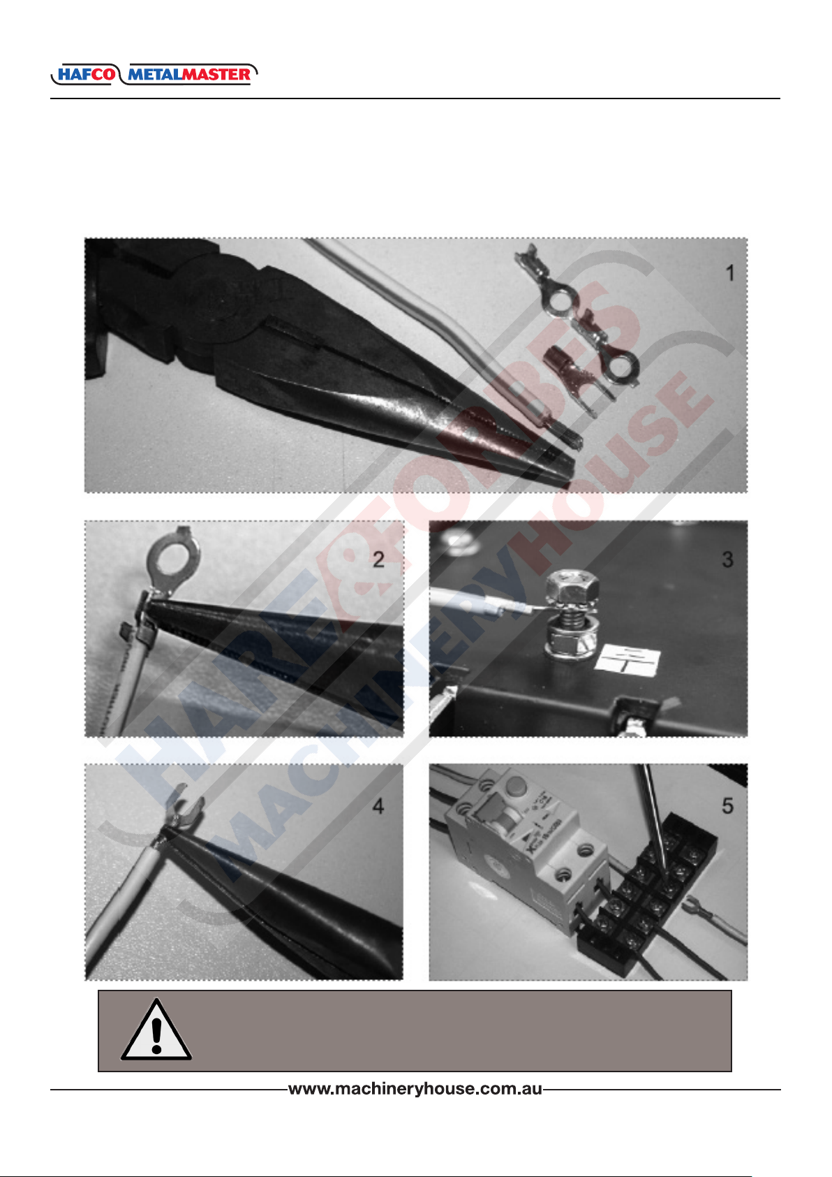
INSTRUCTION MANUAL
XH600
GROUNDING DIAGRAM
ATTENTION: To avoid possible Electrical Shock !! Please install the DRO’s grounding to the
earth terminal of a power socket which is protected by an Earth Leakage Circuit Breaker.
WARNING!
Electricity is dangerous and could cause death
All electrical work must be carried out by a qualied electrician.
www.machineryhouse.co.nz
52
 Loading...