


OIL
DAILY
ASSEMBLY INSTRUCTION
WT3D-6090E WELDING TABLE
Order Code W08458
Due to the weight of the table, Highly recommended to have suitable lifting equipment such
as a forklift with lifting slings & eye bolts or hydraulic engine crane along with the
assistance of a second person to assist during the build of the table, being made from steel
OVERSIZE
This product requires a mechanical lifting aid
WARNING
Suggestion of what you will need
Note - this assembly guide is merely a recommendation and should not be followed blindly, if you do not have the
equipment or the experience necessary to complete this project you should consider seeking advice from a
professional.
• 2pcs x 1000mm of M10 or M12 threaded rod
• 4pcs x 700mm of M10 or M12 threaded rod
• 18pcs x 150mm of M10 or M12 threaded rod
• 48pcs of nuts to match threaded rod
• 96pcs at washers to prevent damage to the table surface
• ‘G’ Clamps (or alternative) with an opening of at least 100mm to secure the legs in place during welding.
• Timber planks to assist in raising the table surface off the bench during assembly.
• MIG or TIG welder
• Angle grinder tted with a ne ap disc
• Soft face hammer to help assemble components
• Engineers le, spanners or shifting spanners
it is heavy and help should be obtained to avoid any injuries. Always remember to wear the
appropriate PPE when working with metal and welding equipment.
Refer to your welder manufacturers
recommendations for the correct settings for your welder to suit the material thickness.
NOTE: You may consider to use other methods and tools to help complete your project, the above list is just a sugges-
tion. For example, a small amount of threaded rod can be welded onto the end of solid steel bar rather than buying full
lengths of threaded rod which can save a signicant amount of cost. Please ensure you thoroughly read through these
instructions carefully before starting the assembly process to ensure you fully understand every aspect of the build to
ensure a successful outcome.
Getting Started
Before starting the assembly ensure you have the correct tools & equipment to successfully assemble the table
whilst making sure you are wearing the appropriate Safety PPE.
Check for Burrs
It is normal for the components to have small burrs or minor imperfections as part of the laser cutting process. While
wearing protective gloves, check the edges of the individual pieces and visually inspect them for any small burrs.
If you do happen to nd one, use a le to remove any burrs, being careful not to remove too much excess material as
it may affect the end result.
Clean Components
The components are supplied with a thin layer rust preventative oil coating to protect it from rust, however, this lm
can affect the quality of the welds if it isn’t removed. Before you start assembling the table, ensure you wipe the
individual pieces down with an appropriate oil & grease remover.
Page 1
ASSEMBLY INSTRUCTION
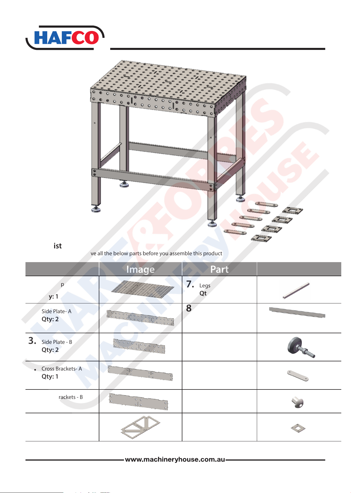
Parts list
Please check that you have all the below parts before you assemble this product
Part PartImage Image
1. Table Top
Qty: 1
2. Side Plate- A
Qty: 2
3. Side Plate - B
Qty: 2
4. Cross Brackets- A
Qty: 1
5. Cross Brackets - B
Qty:2
7. Legs
Qty:4
8. Leg Brace
Qty:4
9. Adjustable feet
Qty:4
10. Assembly Straps
Qty:5
11. Mounting Screws
Qty:16
6. Base Plate
Qty:2
12. Castor Plates
Qty:4

ASSEMBLY INSTRUCTION
Place the tabletop on top of timber planks or, alternatively, sawhorses. It is best to have the timbers
spaced evenly to distribute the weight evenly and reduce distortion during assembly.
Ensure the tabletop is level and doesn’t rock from side to side, this will help ensure the
components t together correctly.
Step 1
Insert the ribs into the underside of the
tabletop as shown, they should t
together rmly with only a small
amount of clearance between the
components. Use a soft-face
hammer to lightly tap the components
into place. If they do not t correctly
the rst time, be sure to check for any
small burrs and then try again.
Step 2
Add the next 2 ribs, (Part 5)
Step 3
This step will require some temporary
clamps or tie downs to help hold all the
pieces in place, This will help to square
up the sides of the table and t each
piece into the correct positions.
Add (Parts 2 & 3)
Page 3

ASSEMBLY INSTRUCTION
Step 4
With the assistance of a second person
begin to install 2 opposing table sides,
use several pieces of the threaded rod
to hold the opposing piece in place
during the process. Add the next 2 opposing sides, also using the threaded
rod to hold the pieces in place. Ensure
the nuts on the threaded rod are only
tightened just enough to hold the
pieces in place & do not over tighten
them.
Step 5
Install corner plates (Part 6) into each
corner, use a soft face hammer to
lightly tap components into place to
ensure they are correctly seated.
Step 6
Insert the threaded rods into the
table in both holes of the leg plates and
make sure they line up with the
corresponding holes on the table top.
This is perhaps the most crucial step of
the construction, this will make sure the
table is perfectly square.
(Make sure you place washers in
between the nut and the table to
protect the metal from scratches)
Page 4
ASSEMBLY INSTRUCTION
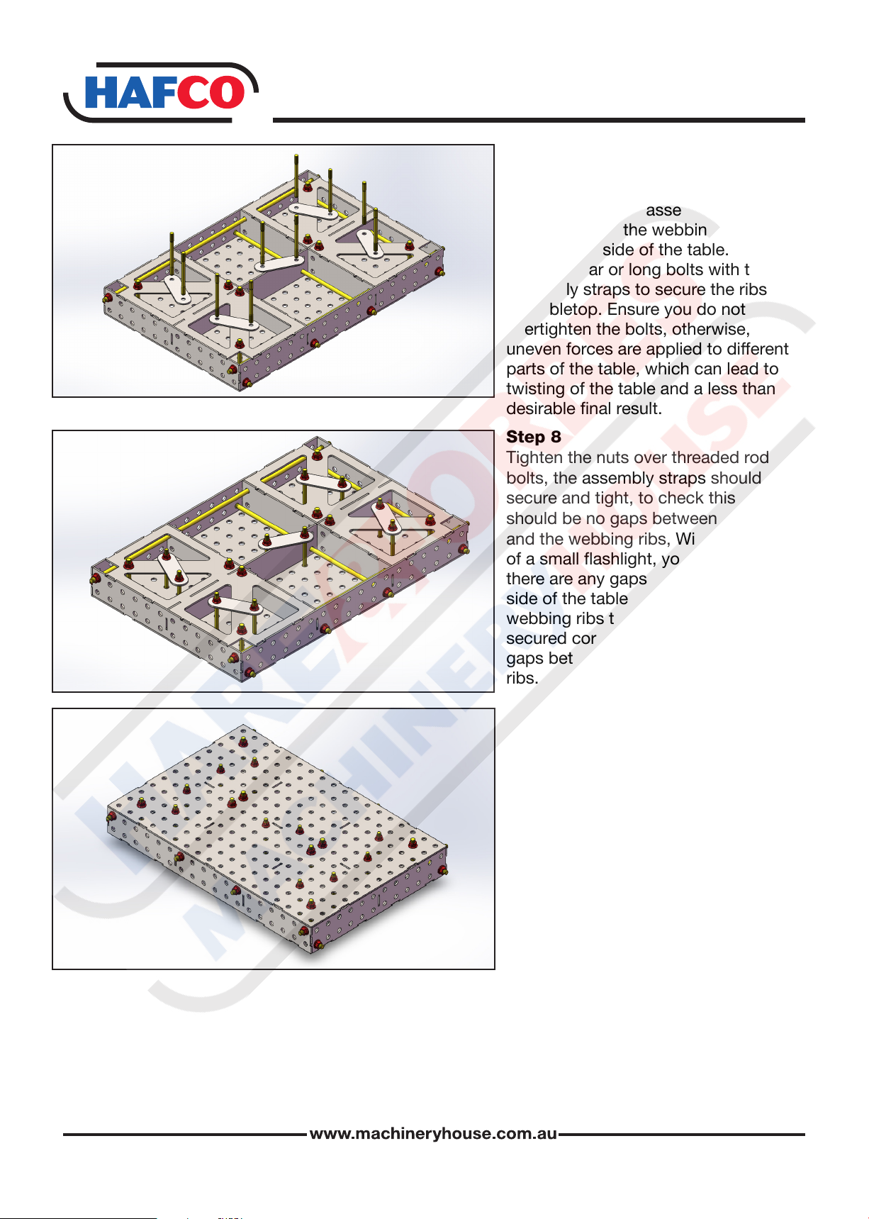
Step 7
To aid in assembly, your welding table
comes supplied with 5 pieces of
pre-drilled at bar assembly straps
to span across the webbing rib joins
on the underside of the table. Use the
threaded bar or long bolts with the
assembly straps to secure the ribs to
the tabletop. Ensure you do not
overtighten the bolts, otherwise,
uneven forces are applied to different
parts of the table, which can lead to
twisting of the table and a less than
desirable nal result.
Step 8
Tighten the nuts over threaded rod or
bolts, the assembly straps should be
secure and tight, to check this there
should be no gaps between the table
and the webbing ribs, With the help
of a small ashlight, you can check if
there are any gaps between the underside of the table surface and the
webbing ribs to ensure they are
secured correctly, there should be no
gaps between the tabletop and the
ribs.
Step 9
With the assistance of lifting
equipment, carefully turn the table over
so that the table surface is upright,
and ensure the welding table is placed
on a at, level surface. Before doing
any welding, check the atness with a
builders level or straight edge.
There should be no gaps between the
tabletop and the ribs. If there are any
gaps the most likely cause is a small
burr, or the bolts have not been
tightened correctly. If this is the case,
disassemble remove the burr and
reassemble. Once again, ensure you
do not overtighten the bolts, otherwise
uneven forces are applied to different
parts of the table, which can lead to a
twisting of the table, leading to a less
than desirable nal result.
Page 5

ASSEMBLY INSTRUCTION
2
6
8
9
3
10
7
5
1
Step 10
Once you are happy with the
assembly and atness, with the
assistance of lifting equipment,
4
carefully turn the table over, weld the
areas highlighted in red in the
sequence as indicated, and weld with
a spiral motion so that the two pieces
fuse together correctly. Less is more
when welding this table together.
More welding means more heat and
higher chances of warping the table
surface.
Step 11
Follow this pattern when welding the
slots together, Less is more when
6
2
3
welding this table together, the more
welding means more heat & higher
chances or warping the table surface.
4
1
5
2
10
6
16
Finish by welding 1 to 4 around the
edge of the table
Step 12
Weld the highlighted areas shown in
red.
12
8
13
7
4
14
3
11
15
5
1
9
Page 6

2
4
5
1
6 3
7
ASSEMBLY INSTRUCTION
Step 13
With the assistance of lifting
equipment, carefully turn the table over
so that the table surface is upright, and
ensure the welding table is placed on a
at, level surface.
Start welding at 1 and work your way
towards 7 on the outside of the table.
Step 14
The 50 x 50mm steel legs come
standard with adjustable feet tted,
plus we also supply caster mounting
plates. Should you want your welding
table to be mobile, simply cut the legs
to the desired length to suit the nished
table height you require,
allowing for the height of the caster
wheels. Weld on the caster mounting
plates as shown & bolt on your optional
caster wheels.
Step 15
Once the table has cooled, remove the
bolts and assembly straps. Again, with
the assistance of lifting equipment,
turn the table over with the webbing
ribs facing up. Clamp the tube legs into
each corner as shown, ensuring the
threaded holes are in the correct
positions to suit the leg bracing.
Lightly clamp the legs into each corner
as shown, then bolt the leg bracing into
place (do not fully tighten the bolts).
Check that the legs are square and
level, then proceed to weld as shown.
Once nished welding, tighten the leg
bracing.
Page 7

ASSEMBLY INSTRUCTION
Step 16
Make sure when welding the legs that
you do not have the welder too hot as
this can blow through the legs, doing
tack welds and taking short breaks on
each hole will help the legs cool down
and to allow the heat not to build up.
Make sure to weld each leg as shown.
The assembly is now complete. With
the assistance of lifting equipment,
carefully turn the table over, put it in
your desired position, and adjust the
leveling feet, check all bolts are
tighten and components are secure.
Your welding table is now ready for
use.
Page 8
 Loading...