

Page 1
EN54 APPROVED 16 - 32 ZONE CONVENTIONAL
CONTROL PANEL
Approved Document UI-XL32-02 Issue 1.0
810a/08
Quick Start Guide
Full manual available from www.haes-systems.com
www.acornfiresecurity.com
www.acornfiresecurity.com
Page 2
IMPORTANT NOTE
PLEASE READ THIS MANUAL BEFORE HANDLING THE EQUIPMENT AND
OBSERVE ALL ADVICE GIVEN IN IT
THIS PARTICULARLY APPLIES TO THE PRECAUTIONS NECESSARY TO AVOID
E.S.D
The panel is safe to operate provided it has been installed in compliance with the manufacturer’s instructions
The panel is safe to operate provided it has been installed in compliance with the manufacturer’s instructions
and used in accordance with this manual.
and used in accordance with this manual.
Hazardous voltages are present inside the panel—DO NOT open it unless you are qualifi ed and authorised
Hazardous voltages are present inside the panel—DO NOT open it unless you are qualifi ed and authorised
to do so. There is no need to open the panel’s enclosure except to carry out commissioning, maintenance
to do so. There is no need to open the panel’s enclosure except to carry out commissioning, maintenance
and remedial work. This work must only be carried out by competent service personnel who are fully
and remedial work. This work must only be carried out by competent service personnel who are fully
conversant with the contents of the panel’s installation manual and have the necessary skills for maintaining
conversant with the contents of the panel’s installation manual and have the necessary skills for maintaining
this equipment.
this equipment.
This fi re alarm system requires periodic checks as specifi ed in BS 5839 Part 1 It is the responsibility of the
This fi re alarm system requires periodic checks as specifi ed in BS 5839 Part 1 It is the responsibility of the
system user to ensure it is regularly serviced and maintained in good working order.
system user to ensure it is regularly serviced and maintained in good working order.
Disclaimer
Disclaimer
No responsibility can be accepted by the manufacturer or distributors of this fi re alarm panel for any
No responsibility can be accepted by the manufacturer or distributors of this fi re alarm panel for any
misinterpretation of an instruction or guidance note or for the compliance of the system as a whole. The
misinterpretation of an instruction or guidance note or for the compliance of the system as a whole. The
manufacturer’s policy is one of continuous improvement and we reserve the right to make changes to
manufacturer’s policy is one of continuous improvement and we reserve the right to make changes to
product specifi cations at our discretion and without prior notice. E & O E.
product specifi cations at our discretion and without prior notice. E & O E.
!
IMPORTANT SAFETY NOTES
0832
Haes Systems Ltd, Columbia House, Packet Boat Lane, Cowley Peachey, Uxbridge, UB8 2JP
13
Model Number CPR Number
XL32, 16 - 32 zone conventional panel XL32-16/24/32 0832-CPR-F0837
European Standard EN54-2 : 1997 + A1 : 2006
Control and indicating equipment for fi re detection and fi re alarm systems for buildings.
Provided Options (with requirements):
Output to fi re alarm devices, dependency types ‘A’, ‘B’ & ‘C’, delays to outputs, test condition, output to fi re alarm routing
equipment
European Standard EN54-4 : 1997 + A1 : 2002 + A2 : 2006
Power supply equipment for fi re detection and fi re alarm systems for buildings.
ATTENTION
www.acornfiresecurity.com
www.acornfiresecurity.com
Page 3

XL32 Quick Start Guide Approved Document Ref: UI-XL32-02 Issue 1.0
1
CONTENTS
Page
ABOUT THIS PANEL
2
CABINET DETAILS
2
MAIN PCB TERMINALS
3
TECHNICAL SPECIFICATION
4
POWER SUPPLY MODULE
5
INSTALLATION
6
SAFETY
6
ESD PRECAUTIONS
7
GENERAL
7
SETUP & PROGRAMMING
8
LEVEL 3 ENGINEERING MODE
8
LEVEL 3 ENGINEERING OPTIONS INDEX
9
OPERATING
10
PANEL CONTROLS & INDICATIONS
10
DISABLE MODE
12
TEST MODE
13
FAULT DIAGNOSIS
14
FUNCTIONALITY DURING A SYSTEM FAULT
15
SERVICE & MAINTENANCE
16
SCHEDULE OF TESTING LOG BOOK
16
FALSE ALARMS, FAULTS & ENGINEER VISIT LOG BOOK
20
USER INSTRUCTIONS
23
www.acornfiresecurity.com
www.acornfiresecurity.com
Page 4
XL32 Quick Start Guide Approved Document Ref: UI-XL32-02 Issue 1.0
2
ABOUT THIS PANEL
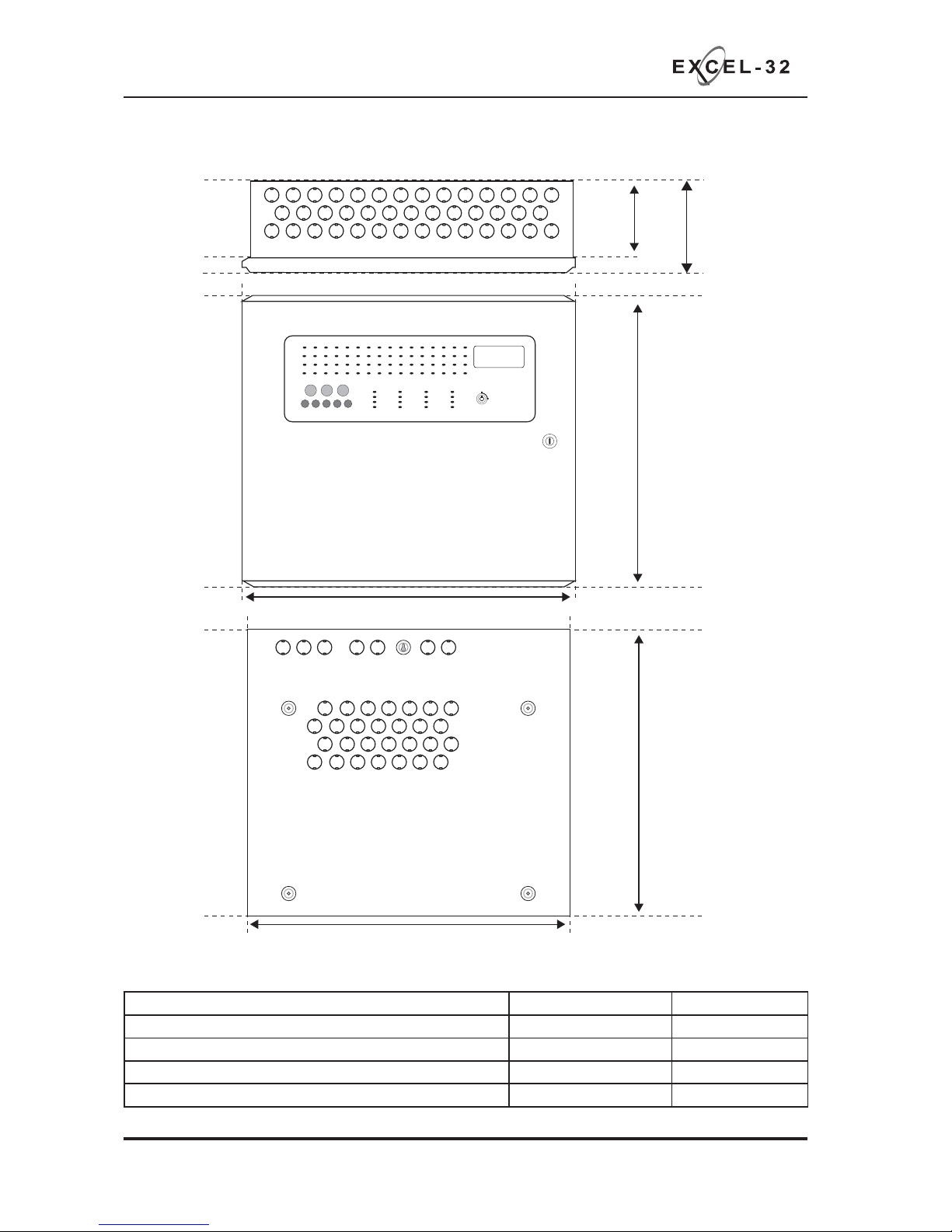
CABINET
107mm
130mm
410mm
465mm
450mm
400mm
450mm
Fire Detection System
Quiesecent and alarm current details for standby battery calculations
Models Standby Current Alarm Current
XL32-16 205mA 300mA
XL32-24 270mA 365mA
XL32-32 320mA 415mA
TPCA05 5.2mA N/A
www.acornfiresecurity.com
www.acornfiresecurity.com
Page 5
XL32 Quick Start Guide Approved Document Ref: UI-XL32-02 Issue 1.0
3
ABOUT THIS PANEL
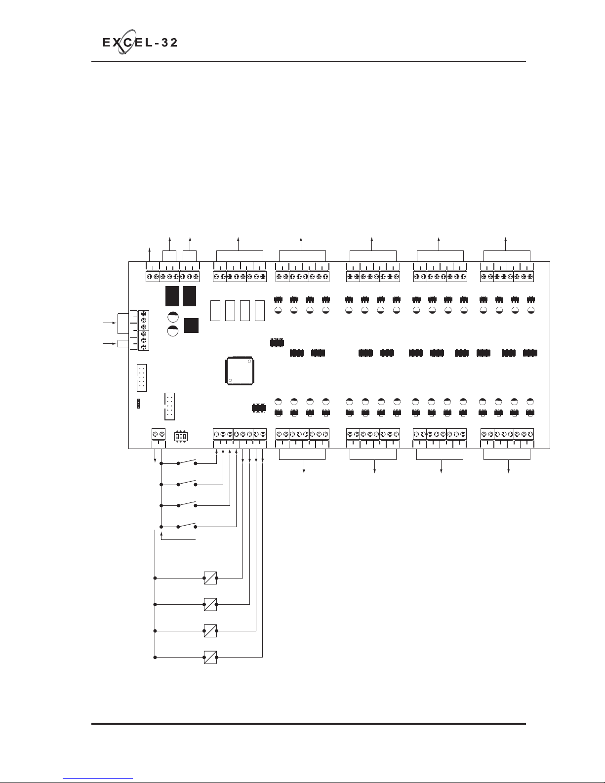
MAIN PCB TERMINALS
PSU
PSUINB PSUINA
+
-+-
+-
+- +- +-+- +-
28V 0V
C NC NO C NC NO
FIRE FAULT
SNDR1 SNDR2
+- +-
SNDR3
SNDR4
ZONE1 ZONE2 ZONE3 ZONE4
+
-+-+-+-
ZONE17 ZONE18 ZONE19 ZONE20
+- +-+- +-
ZONE5 ZONE6 ZONE7 ZONE8
+- +-+- +-
ZONE9 ZONE10 ZONE11 ZONE12
+- +-+- +-
ZONE13 ZONE14 ZONE15 ZONE16
28V
1 2 3
ON
0V INPUTS
RS SA PUL CC
SW -V OUTPUTS
RSGDFLT FR
TX
RX 0V 28V 0V 28V
+
-+-+-+-
ZONE21 ZONE22 ZONE23 ZONE24
+
-+-+-+-
ZONE25 ZONE26 ZONE27 ZONE28
+
-+-+-+-
ZONE29 ZONE30 ZONE31 ZONE32
Common re VFCO relay
unfused. Max 3A @ 30vdc
Common fault VFCO relay
maintained (fail safe) unfused.
Max 3A @ 30vdc
Conventional monitored
sounder circuits, fused @ 500mA
Conventional re zone circuits,
current limit max 50mA, 4K7 EOL
Conventional re zone circuits,
current limit max 50mA, 4K7 EOL
Conventional re zone circuits,
current limit max 50mA, 4K7 EOL
Conventional re zone circuits,
current limit max 50mA, 4K7 EOL
Conventional re zone circuits,
current limit max 50mA, 4K7 EOL
Conventional re zone circuits,
current limit max 50mA, 4K7 EOL
Conventional re zone circuits,
current limit max 50mA, 4K7 EOL
Conventional re zone circuits,
current limit max 50mA, 4K7 EOL
28v output fused @ 500mA
28v output fused @ 500mA
RESET
SILENCE
ALERT (pulsing)
CLASS CHANGE
Switch -ve inputs
To 0V
RESET O/P
DISABLEMENT O/P
FAULT O/P
FIRE O/P
28v +
Programmable outputs
switch -ve
max load 40mA
FROM PSU
28v supply inputs
PSU comms
www.acornfiresecurity.com
www.acornfiresecurity.com
Page 6
XL32 Quick Start Guide Approved Document Ref: UI-XL32-02 Issue 1.0
4
ABOUT THIS PANEL
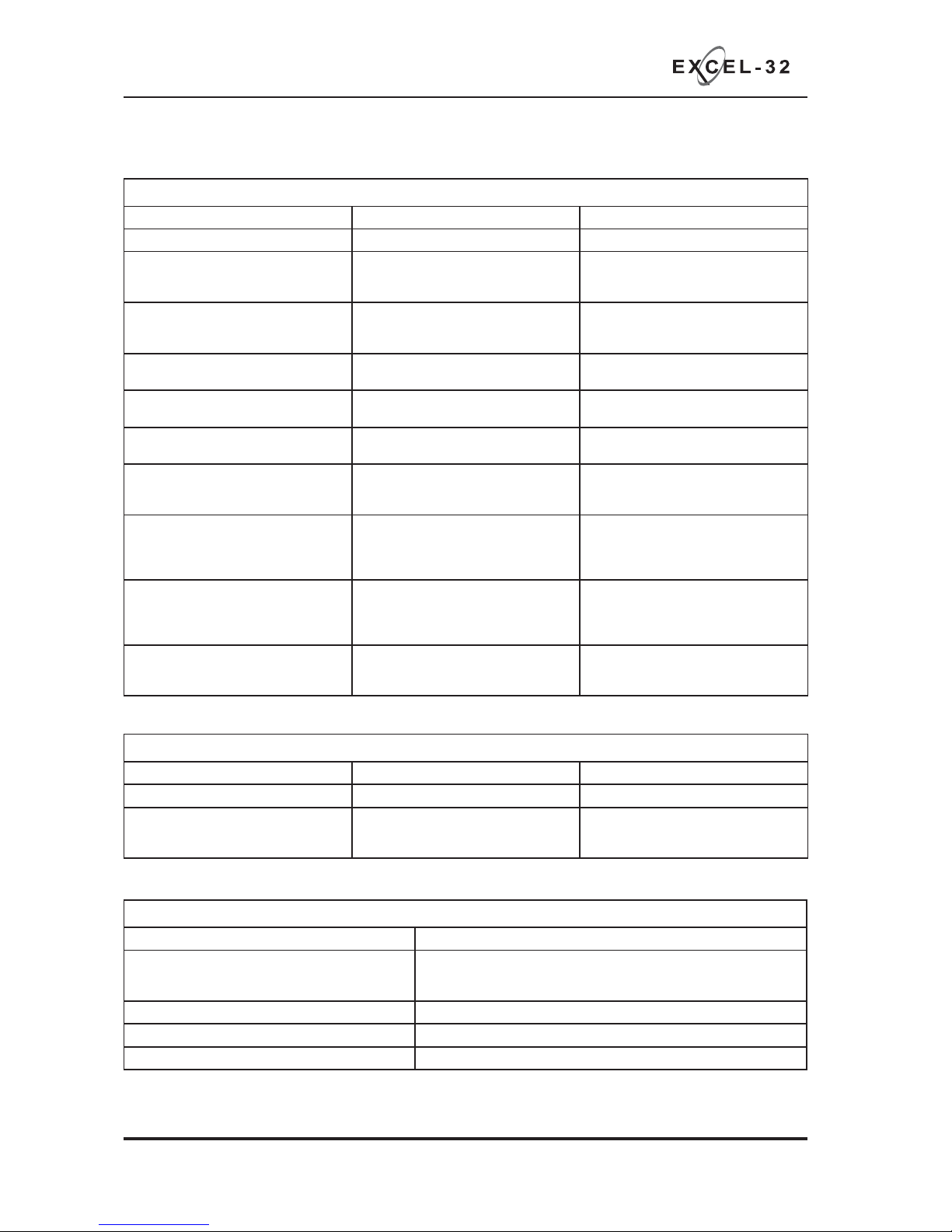
General Specifi cation
Enclosure Steel IP30. Epoxy powder coated Interpon Radon, silver grey
Cabling Fire resistant screened cable, minimum size 1mm2. Max cable length
1Km (20 Ohm). FireBurn, FP200 or equivalent (max capacitance 1uF,
max inductance 1 millihenry).
Temperature range -5 deg C to +40 deg C max RH 95%
Number of conventional detection circuits 16 - 32
Conventional detector compatibility Apollo: S65, Orbis. / Hochiki CDX. / Nittan EV
TECHNICAL SPECIFICATION
Electrical Specifi cation Inputs & Outputs - TPCA11-16/24/32 Main PCB
Terminal capacity 0.5mm2 to 2.5mm2 solid or stranded wire.
PSU TX/RX Power supply data control lines. RS232 data.
PSU Input A +/-, B +/- 28vdc supply input. Diode protected for
reversal and independent short circuit.
Max current 5 amps.
Max input current 5 amps. Input voltage
19.8vdc to 29.7vdc.
28v+, 0v- power output 1 & 2 28vdc supply output for fi re alarm
accessory relays etc. Max continuous
use = 400mA.
Fused @ 500mA. Fuse = 500mA
resettable fuse.
Common fi re relay Fire relay contact. Clean C/O.
Max 3A @ 30vdc.
Unfused
Common fault relay Maintained fault relay contact. Clean C/O
Max 3A @ 30vdc.
Unfused
Outputs: FR (fi re), FLT (fault), RS (reset),
GD (general disablement)
Switched -ve voltage outputs for relay
control.
Overload voltage protected to 52vdc.
Current limited 680R. Max load = 40mA
Inputs; CC, PUL, SA, RS Switched -ve inputs, connect to 0v to
trigger. Max input voltage = 28vdc. Non
latching, max resistance 100R.
Protected via 10K Ohm impedance, 3v6
zener diode.
SNDR 1 - 4 28vdc polarity reversal monitored
sounder outputs to fi re alarm devices.
4K7 Ohm 5% 0.25W EOL resistor.
Monitoring current limit 28mA, fused @
500mA. Typical max load 22 devices @
18mA each per circuit. Ensure 5A is not
exceeded.
Zone 1 - 32 Fire alarm zone circuits. Conventionally
wired detection circuit. 4K7 Ohm 5%
0.25W EOL resistor.
Monitoring current limit 50mA. Max 30
devices per zone. Total 512 devices
shared between 32 zones. Typically 16
per zone.
Fire alarm routing output (optional) 28vdc polarity reversal monitored output
to fi re alarm routing equipment. 4K7 Ohm
5% 0.25W EOL resistor.
Monitoring current limit 28mA, fused @
500mA.
Electrical Specifi cation Inputs & Outputs - TPCA05 comms PCB
Comms A - B RS485 Repeater Comms, fused @ 20mA
28v Nominal 19.8 to 29.7vdc Supply output Fused @ 500mA
Programmable outputs 1 - 6 Switched -ve outputs Overload voltage protected to 52vdc
Current limited 680R
Max load = 40mA
www.acornfiresecurity.com
www.acornfiresecurity.com
Page 7
XL32 Quick Start Guide Approved Document Ref: UI-XL32-02 Issue 1.0
5
ABOUT THIS PANEL
POWER SUPPLY MODULE
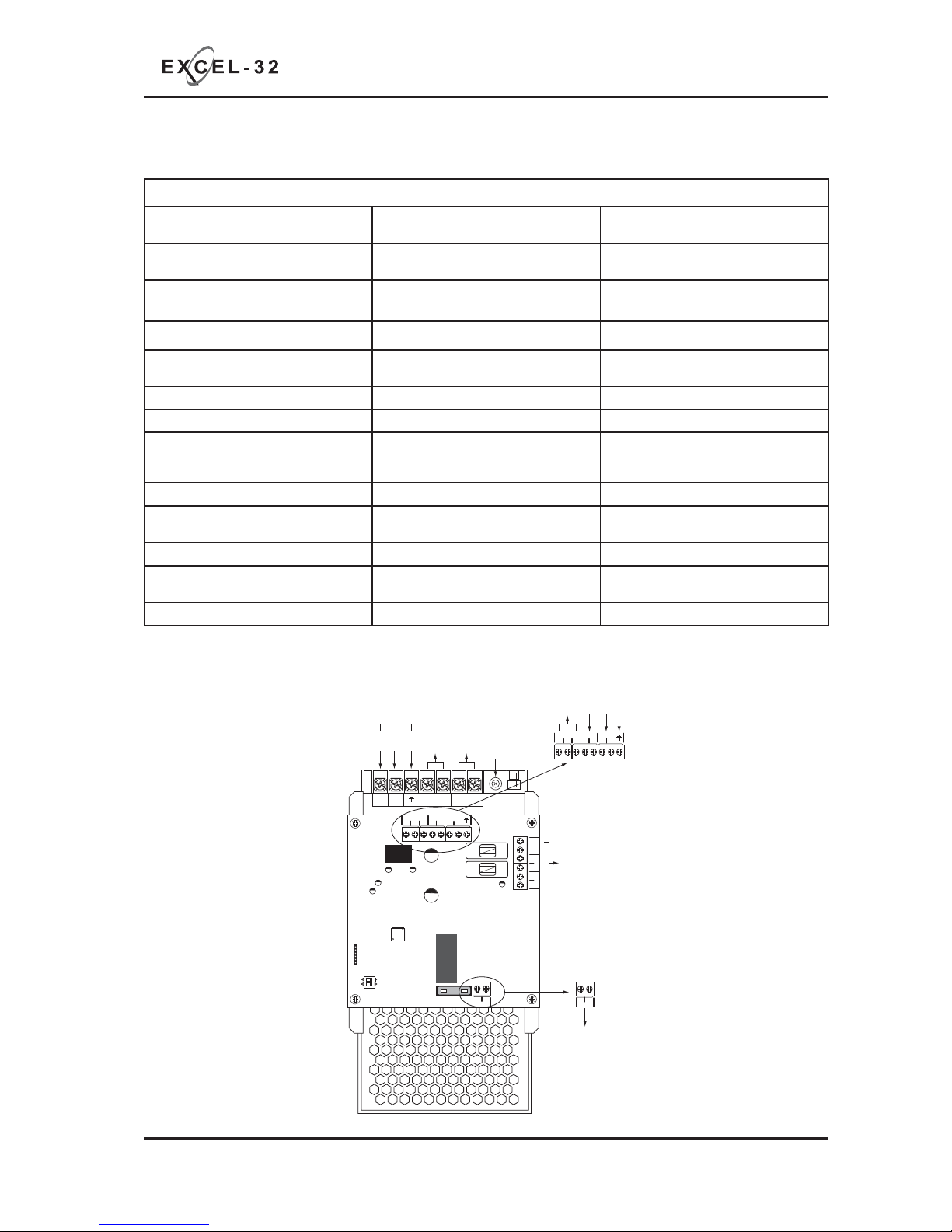
Power Supply Specifi cation
Mains supply 230vac +10% / -15% 50Hz max current
1.9A
Mains supply fuse 3.15 Amp (F3.15A 250V) Not accessible for servicing. Internal to
switch mode power unit
Internal power supply rating 5.0 Amps total including battery charging Maximum load shared between outputs
= 5A
Power supply output voltage 19.8 - 29.7vdc Tolerance +/- 0.1%
Maximum continuous load for battery
standby (ImaxA)
ImaxA = 1.26A ImaxB not specifi ed
Minimum current drawn by panel 16 Zone = 205mA 32 Zone = 320mA
Maximum ripple 150 mV p-p Supply and charger fault monitored
Min/max battery size and type 2 x 18.0Ah 12volt VRLA. Use Yuasa NP
range batteries, NP18-12B (17.2Ahrs) for
LPCB approved panels
Other equivalent batteries may be
used but have not been tested for the
purposes of EN54 approval.
Battery charging voltage 27.3 vdc nominal at 20 deg C Temperature compensated
Battery charging output current 5.0A PSU 2A
Current limited 2 Amps
Battery high impedance fault (Batt Hi Z) Resistance > 1 Ohm 1 hour reporting time
Max current drawn from batteries 7.5 Amps with main power source
disconnected. Battery fuse 7.5A ATO
Min current supplied by PSU Imin 40mA
PSU FAULT
CNCNO
-
0V
0V
-
0V
+
+
30V
PSU FAULT
CNCNO
-0V-
0V
+
+
30V
1 2
ON
MODE
CAL
+-
BATT
+-
BATT
7.5
BATTERY
FUSE 7.5A
28V
0V
28V
PSU A
PSU B
TX RX
PSU
+V -V NL
Live
Neutral
Earth
Earth (monitoring point)
Mains Input
To 0V on TPCA12
To 30V on TPCA12
From V+ on Power Module
From V- on Power Module
Fault Relay VFCO
To Batteries
Output Voltage Adjust
(default setting 28.6v @ 20
o
C)
To Control Panel
Main PCB (TPCA11)
TPCA12
PSUM-5A
www.acornfiresecurity.com
www.acornfiresecurity.com
Page 8
XL32 Quick Start Guide Approved Document Ref: UI-XL32-02 Issue 1.0
6
INSTALLATION
SAFETY
Suppliers of articles for use at work are required under section 6 of the Health and Safety at Work Act 1974
Suppliers of articles for use at work are required under section 6 of the Health and Safety at Work Act 1974
to ensure as reasonably as is practical that the article will be safe and without risk to health when properly
to ensure as reasonably as is practical that the article will be safe and without risk to health when properly
used. An article is not regarded as properly used if it is used “without regard to any relevant information or
used. An article is not regarded as properly used if it is used “without regard to any relevant information or
advice” relating to its use made available by the supplier.
advice” relating to its use made available by the supplier.
It is assumed that the system, of which this control panel is a part, has been designed by a competent fi re
It is assumed that the system, of which this control panel is a part, has been designed by a competent fi re
alarm system designer in accordance with BS 5839 Part 1 and with regard to BS EN 54 parts 2 and 4 in
alarm system designer in accordance with BS 5839 Part 1 and with regard to BS EN 54 parts 2 and 4 in
the case of control equipment and power supplies. Design drawings should be provided to clearly show
the case of control equipment and power supplies. Design drawings should be provided to clearly show
the position of any fi eld devices and ancillary equipment.
the position of any fi eld devices and ancillary equipment.
This product should be installed, commissioned and maintained by, or under the supervision of, competent
This product should be installed, commissioned and maintained by, or under the supervision of, competent
persons according to good engineering practice and,
persons according to good engineering practice and,
(i) BS 7671 (IEE wiring regulations for electrical installations)
(i) BS 7671 (IEE wiring regulations for electrical installations)
(ii) Codes of Practice
(ii) Codes of Practice
(iii) Statutory requirements
(iii) Statutory requirements
(iv) Any instructions specifi cally advised by the manufacturer
(iv) Any instructions specifi cally advised by the manufacturer
According to the provisions of the Act you are therefore requested to take such steps as are necessary to
According to the provisions of the Act you are therefore requested to take such steps as are necessary to
ensure that any appropriate information about this product is made available by you to anyone concerned
ensure that any appropriate information about this product is made available by you to anyone concerned
with its use.
with its use.
This equipment is designed to be operated from 230V AC 50/60 Hz mains supplies and is of Class I
This equipment is designed to be operated from 230V AC 50/60 Hz mains supplies and is of Class I
construction. As such it must be connected to a protective earthing conductor in the fi xed wiring of the
construction. As such it must be connected to a protective earthing conductor in the fi xed wiring of the
installation. Failure to ensure that all conductive accessible parts of this equipment are adequately bonded
installation. Failure to ensure that all conductive accessible parts of this equipment are adequately bonded
to the protective earth will render the equipment unsafe.
to the protective earth will render the equipment unsafe.
This equipment must only be installed and maintained by a suitably skilled and technically
competent person.
THIS IS A PIECE OF CLASS 1 EQUIPMENT AND MUST BE EARTHED
!
These panels are designed to comply with the requirements of EN 54 part 2.
These panels are designed to comply with the requirements of EN 54 part 2.
Installation of the panel should only be carried out by qualifi ed personnel. The electronic components
Installation of the panel should only be carried out by qualifi ed personnel. The electronic components
within the panel can be damaged by static charge. Suitable precautions must be taken when handling
within the panel can be damaged by static charge. Suitable precautions must be taken when handling
circuit boards. Never insert or remove boards or components, or connect cables, with the mains power
circuit boards. Never insert or remove boards or components, or connect cables, with the mains power
on or batteries connected.
on or batteries connected.
Equipment Guarantee
This equipment is not guaranteed unless the complete system is installed and commissioned in accordance with the laid
down national standards by an approved and competent person or organisation.
This product has been manufactured in conformance with the requirements of all applicable EU Council
Directives
www.acornfiresecurity.com
www.acornfiresecurity.com
Page 9

XL32 Quick Start Guide Approved Document Ref: UI-XL32-02 Issue 1.0
7
INSTALLATION
ESD PRECAUTION
GENERAL
MOUNTING THE CABINET
Electronic components are vulnerable to damage by Electrostatic Discharges (ESD). An ESD wrist strap,
Electronic components are vulnerable to damage by Electrostatic Discharges (ESD). An ESD wrist strap,
suitably grounded, should be worn at all times when handling pcbs. These wrist straps are designed to
suitably grounded, should be worn at all times when handling pcbs. These wrist straps are designed to
prevent the build up of static charges, not only within a persons body, but on many other materials.
prevent the build up of static charges, not only within a persons body, but on many other materials.
ESD damage is not always evident immediately, faults can manifest themselves at anytime in the future.
ESD damage is not always evident immediately, faults can manifest themselves at anytime in the future.
All pcbs should be stored in static shielded bags (silvered) for safe keeping, when not mounted in the
All pcbs should be stored in static shielded bags (silvered) for safe keeping, when not mounted in the
control panel.
control panel.
Care should be taken with regards to avoiding the close proximity of high voltage cables or areas likely
Care should be taken with regards to avoiding the close proximity of high voltage cables or areas likely
to induce electrical interference. Earth links should be maintained on all system cables and grounded in
to induce electrical interference. Earth links should be maintained on all system cables and grounded in
the control panel.
the control panel. The detection and sounder circuit cabling is classed as extra low voltage and must be
segregated away from mains voltage.
• Any junction boxes used should be clearly labelled FIRE ALARM.
• Any ancillary devices, e.g. door retaining magnets, must be powered from a separate power source.
• Any coils or solenoids used in the system must be suppressed, to avoid damage to the control
equipment.
The site chosen for the location of the panel should be clean, dry and not subject to shock or vibration.
The site chosen for the location of the panel should be clean, dry and not subject to shock or vibration.
Damp, salt air or environments where water ingress or extremes of temperature may affect the panel must
Damp, salt air or environments where water ingress or extremes of temperature may affect the panel must
be avoided. The temperature should be in the range -5° to +40°C, and the relative humidity should not
be avoided. The temperature should be in the range -5° to +40°C, and the relative humidity should not
exceed 95%.
exceed 95%.
Before mounting the cabinet remove the main PCB.
Remove the power supply module connecting wires from the main PCB, taking care to note where to reconnect them. The main PCB can then be carefully pulled off it’s mounting clips.
Secure the cabinet to the wall using the four indented holes in the back box. Ensure the box is mounted
level and in a convenient location where it may be easily operated and serviced.
External cables should be glanded via preformed knockouts at the top and rear of the cabinet. Remove
any knockouts and ensure the cabinet is clear of swarf etc prior to refi tting the PCB. Always ensure that if
a knockout is removed, the hole is fi lled with a good quality cable gland. Any unused knockouts must be
securely blanked off.
Knockouts should be removed with a sharp tap at the
rim of the knockout using a fl at 6mm broad bladed
screwdriver.
Use of excessive force will damage the enclosure
around the knockout.
www.acornfiresecurity.com
www.acornfiresecurity.com
Page 10
XL32 Quick Start Guide Approved Document Ref: UI-XL32-02 Issue 1.0
8
SETUP & PROGRAMMING
LEVEL 3 ENGINEERING OPTIONS
PSU
PSUINB PSUINA
+
-+-
+-
+- +-+- +-+
28V 0V
C NC NO C NC NO
FIRE FAULT SNDR1 SNDR2
+- +-
SNDR3
SNDR4
ZONE1 ZONE2 ZONE3 ZO
+
-+-+-+
ZONE17 ZONE18ZONE19 ZON
28V
1 2 3
ON
0V INPUTS
RS SA PUL CC
SW -V OUTPUTS
RSGDFLT FR
TX
RX 0V 28V 0V 28V
1 2 3
ON
A series of programmable engineering options are available. These
programming modes are initiated by entering a four digit code using
buttons 1 - 4 on the keypad followed by the ENTER button.
1 2 3
ON
P
RESOUND SILENCE RESET
ENTER
1234
Disable
Mode
Tes t
Mode
Mute
Buzzer
Tes t
Lamps
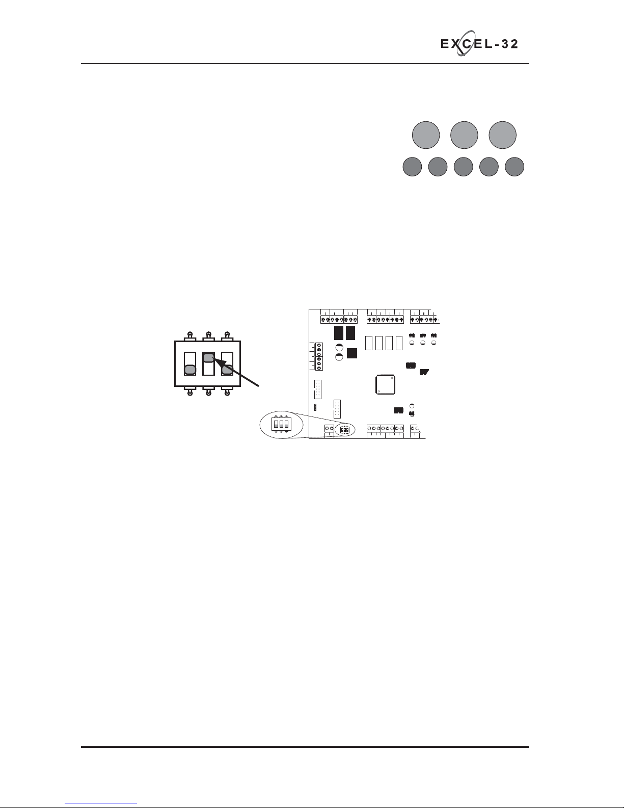
To access Level 3 options, fi rst set switch 2 on the 3 way DIL switch located on the main PCB to the
‘ON’ position. Then activate the controls by turning the key switch or by entering the four digit code (see
Activate Controls in the OPERATING section).
Once the controls are active, the ‘Access Level’ indicator will pulse to signify that Level 3 access is active.
For detailed programming instructions please download the full instruction manual (UI-XL32-01)
at www.haes-systems.com
www.acornfiresecurity.com
www.acornfiresecurity.com
Page 11
XL32 Quick Start Guide Approved Document Ref: UI-XL32-02 Issue 1.0
9
SETUP & PROGRAMMING
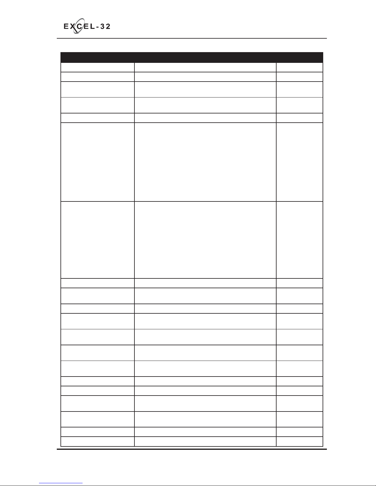
PROGRAMMING OPTIONS INDEX
Option/Setting Description Code(s)
View History View the last 40 events 1111
Set Fault Buzzer Volume Set the fault buzzer volume to high or low 2224
Clear All Disablements Remove all disablements which have been set for any
zone, sounder circuit, output or delay
1121
Initialise Factory Settings Restores all programming, test modes and disablements
back to factory default settings
1113
Power Supply Settings Set options for integral power supply 2122
Panel Wide Settings • Change/remove keypad access code
• Set number of repeater panels on system
• Set time for panel delay timer
• Change network/repeater comms monitoring type
• Set number of output cards
• Inhibit muted tone beeps
• Inhibit network alarms & faults for panel
• Set number of network slave panels on system (Master
Panel only)
• Inhibit network slave panel fi re & fault buzzer
2123
Zone Function Settings • Set zone to latching or non latching
• Set zone to old B.S (short circuit = fi re)
• Set zone for use with MTL5061 I.S. barrier
• Set zone to silent mode (provides visual & audible
indication at the panel but no sounder operation)
• Turn off priority alarm feature for zone
• Turn off detector removal monitoring for zone
• Set detector removal monitoring type for zone (Schottky
or Zener diode detector bases)
• Sprinkler/pump monitoring function
3121
Dependancy Mode Set panel & zones to dependancy mode A, B or C 2114, 2124, 2134
EN54 Sounder Resound
Options
Set zones to not resound alarms after an initial fi re
condition
1114
Delays to Outputs Apply delays to outputs in response to selected zones 2323
Input Functions Change the default functions of the Class Change and
Alert inputs
4141
Output Programmability &
Miscellaneous
Set panel outputs to be programmable, switch on fault
latching, invert fault output, set F.A.R.E output
4142
Panel Output Zonal
Responses
Set how each output or sounder circuit responds for each
zone (off, continuous or pulsing)
4242, 4342
Panel Output Functional
Options
Change the default output responses to ‘Silence Alarms’,
‘Evacuate’, ‘Class Change’, ‘Alert’ and ‘Delay’
4244, 4344
Network Sounder Responses Set local sounder cct responses to network fi res 4324
Network Output Responses Set local output & relay responses to network fi res 4224
Comms PCB Output Zonal
Responses
Set how each comms PCB o/p responds for each zone
(off, continuous or pulsing)
4243
Comms PCB Output
Functional Options
Change the default comms PCB o/p responses to ‘Silence
Alarms’, ‘Evacuate’, ‘Class Change’, ‘Alert’ and ‘Delay’
4244, 4344
System Diagnostics Mode Tests system PCB confi g setup for fault diagnosis 3114
Repeater Programming Repeater panel setup & programming 4443
www.acornfiresecurity.com
www.acornfiresecurity.com
Page 12
XL32 Quick Start Guide Approved Document Ref: UI-XL32-02 Issue 1.0
10
OPERATING
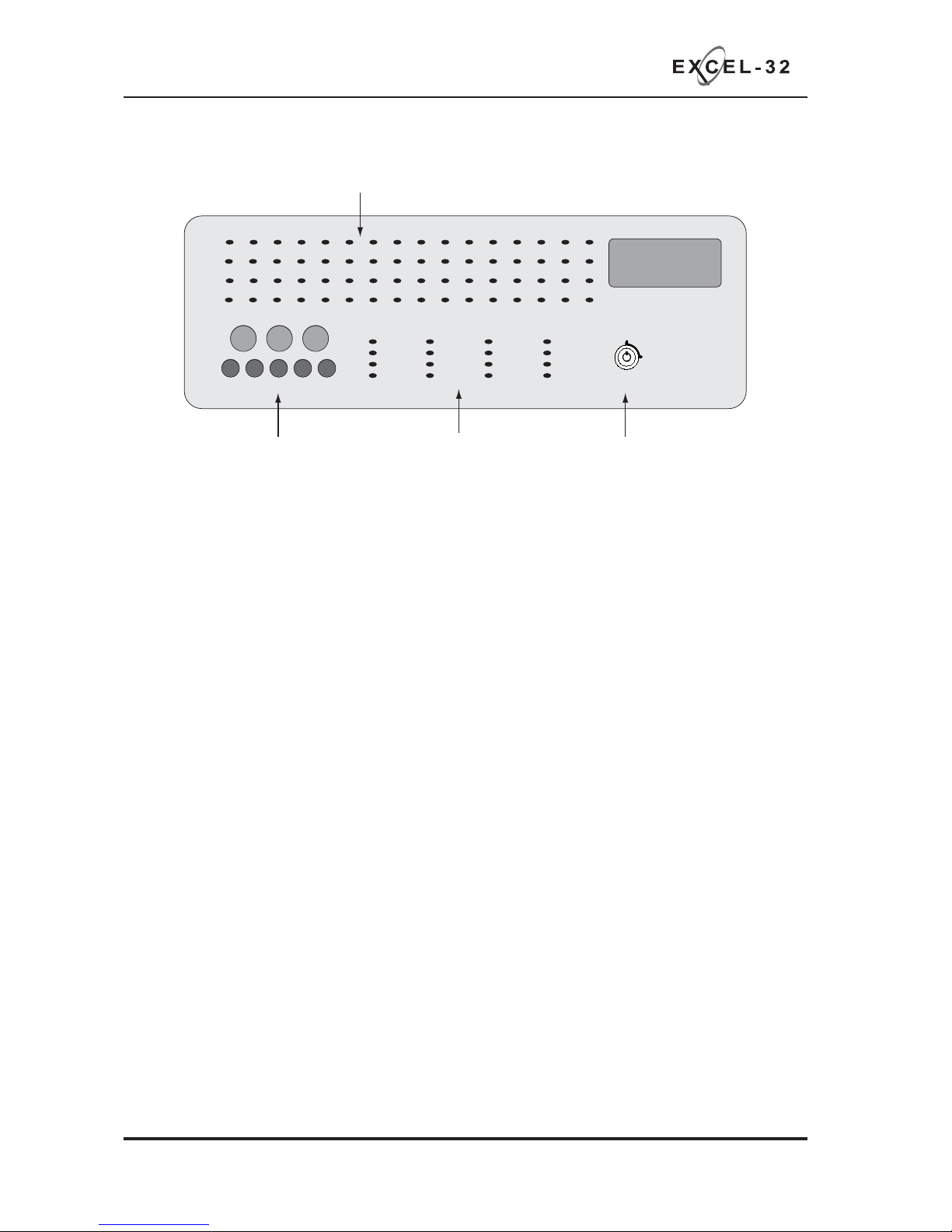
PANEL CONTROLS & INDICATIONS
Zonal Fire & Fault Indicator LEDs
Fire Detection System
Zones in Fire
Zones in Fire
Zone Fault
Disabled / Test
Zone Fault
Disabled / Test
RESOUND SILENCE RESET
ENTER
12
34
Disable
Mode
Test
Mode
Mute
Buzzer
Test
Lamps
12345678910111213141516
17 18 19 20 21 22 23 24 25 26 27 28 29 30 31 32
On
Off
Activate
Controls
Supply Healthy
General Fire
General Fault
General Disablement
Test Mode
Sounder Status
Aux Output Status
Power Supply Fault
Delay Status
Repeater Fault
Battery Fault
Earth Fault
Fire Routing Active
Fire Routing Fault
System Fault
Access Level
8 Button Keypad For Controls
And Programming
Activate Controls Key Switch
Status Indicator LEDs
Activate Controls
In normal standby mode the keypad controls are inactive to protect from unauthorised operation. Controls
can be activated by using the ‘Activate Controls’ key switch or by entering a four digit code using the
keypad.
The use of a code entry to activate the controls is enabled by default but can be disabled in the Level 3
engineering functions.
To activate the controls using the key switch;
Turn the key clockwise to the ‘On’ position. The ‘Access Level’ indicator LED will light and all buttons on
the keypad will now be operational. To deactivate the controls, turn the key back to the ‘Off’ position and
the ‘Access Level’ indicator LED will extinguish.
If the key switch is in the ‘On’ position the keypad will remain active.
NOTE : It is not possible to remove the key in the ‘On’ position.
To activate the controls using the keypad;
Enter the four digit code using buttons 1 - 4. The factory default code is 1-2-3-4 but can be changed in
the engineering functions. After entering the four digit code press the ‘ENTER’ button. The ‘Access Level’
indicator LED will light and all buttons on the keypad will now be operational.
After activation by code entry, controls will automatically deactivate again after 2 minutes and the panel
will return to standby mode.
The test lamps and mute buzzer functions are operational without the need to activate controls.
www.acornfiresecurity.com
www.acornfiresecurity.com
Page 13
XL32 Quick Start Guide Approved Document Ref: UI-XL32-02 Issue 1.0
11
OPERATING
Keypad
RESOUND (red):
Use to resound the alarms after they have been silenced. Can also be used to invoke full evacuation.
SILENCE (blue):
Use to silence the sounders during an alarm condition.
RESET (green):
Resets the panel back to standby mode.
1: (Disable Mode)
With controls inactive, use to initialise code entry mode for activation of controls. With controls active,
use to disable zones, sounder circuits or aux outputs (see DISABLE MODE section). Also has the
numeric value 1 for code entry.
2: (Test Mode)
With controls inactive, use to initialise code entry mode for activation of controls. With controls active,
use to put zones or sounders circuits into test mode (see TEST MODE section). Also has the numeric
value 2 for code entry.
3: (Mute Buzzer)
Mutes the panels internal fi re and fault buzzer. (The buzzer will still blip every 5-6 seconds during a
fi re or fault condition). This function is operational without the need to activate controls. Also has the
numeric value 3 for code entry.
4: (Test Lamps &
Buzzer)
Use this button to illuminate all LEDs and sound the internal buzzer to check that they are working
correctly. This function is operational without the need to activate controls. Also has the numeric value
4 for code entry.
ENTER:
This button is used to confi rm code entries. It can also be used for fault diagnosis (see FAULT
DIAGNOSIS section).
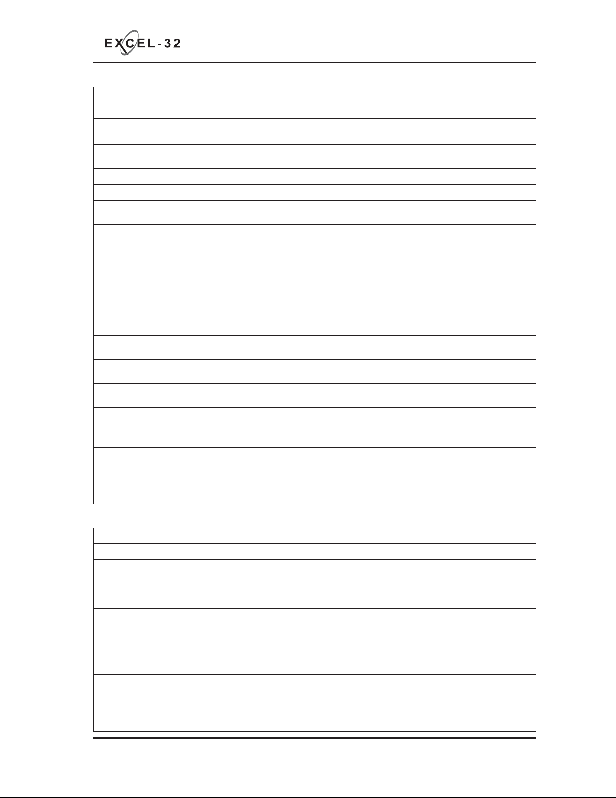
LED On LED Pulsing
Zones in Fire 1 - 32
N/A Indicates alarm condition in zone.
Zone Fault/Disabled/Test
1 - 32
Indicates zone circuit is disabled or in test
mode.
Indicates a fault in the zone circuit.
Supply Healthy:
Indicates mains and/or battery supply is
present.
N/A
General Fire:
N/A Indicates panel is in alarm condition.
General Fault:
N/A Indicates one or more faults are present.
General Disablement:
Indicates one or more circuits have been
disabled.
Indicates disablement selection mode is
active.
Test Mode:
Indicates one or more circuits are in test
mode
Indicates test mode selection is active.
Sounder Status:
Indicates sounder circuits have been
disabled or are in test mode
Indicates a fault on one or more sounder
circuits.
Aux Output Status:
Indicates auxiliary outputs have been
disabled.
N/A
Power Supply Fault:
N/A
Indicates a power supply fault on mains
power input.
Delay Status:
Delays are confi gured Delay is running
Repeater Fault:
N/A
Indicates a fault on one or more repeater
panels
Battery Fault:
N/A
Indicates a battery missing, high impedance
or voltage fault.
Earth Fault
N/A
Indicates an earth leakage to 28v supply,
zone or sounder circuit.
Fire Routing Active:
N/A
Fire routing signal (if confi gured) has been
sent.
Fire Routing Fault:
N/A Indicates a fault with fi re routing signal path.
System Fault:
Indicates a system failure, panel not
functional or the internal PCB confi guration
has not been set up correctly (see page 26).
Indicates the panel has recovered from a
system fault.
Access Level:
Indicates controls are active (access level 2).
Indicates panel is in confi guration mode
(access level 3).
Status LED Indicators
www.acornfiresecurity.com
www.acornfiresecurity.com
Page 14

XL32 Quick Start Guide Approved Document Ref: UI-XL32-02 Issue 1.0
12
OPERATING
Disable Mode is used to disable or isolate individual zone circuits or all sounder circuits, all auxiliary
outputs and any delays to outputs.
To initialise Disable Mode fi rstly activate the controls by turning
the key switch or by entering the four digit code. Then press and
hold the Disable Mode button (1) for 3 seconds.
After 3 seconds the panel will bleep and the General Disablement
LED and Zone 1 Fault LED will pulse slowly, indicating that Zone
1 is in disable selection mode.
Pressing the Disable Mode button again will move disable selection mode to Zone 2 and the Zone 2 Fault
LED will be pulsing instead. Subsequent presses will move the selection to Zones 3 - 32, dependant on the
number of zones fi tted to the panel. I.e up to zone 16 on a 16 zone, 24 on a 24 zone or 32 on a 32 zone.
After the last available zone the next press will move the selection mode to the sounder circuits, indicated
by the Sounder Status LED and then to the Aux outputs, indicated by the Aux Output Status LED and
fi nally to the Delay LED. Pressing the button once more will move the selection back to Zone 1 again.
When the desired circuit, outputs or delays to be disabled is indicated
by a slow pulsing LED, use the ENTER button to select it. Once selected
the indicator LED will change to a rapid pulse. Pressing ENTER again will
toggle the circuit between disabled and enabled. Then use Disable Mode
button again to move to the next circuit. Any or all circuits, outputs or
delays can be disabled simultaneously.
When all disablements have been set, press and hold the Disable Mode
button for 3 seconds again. This will exit the disable selection mode and the panel will return to standby.
All disabled circuits and the General Disablement will now be indicated by a steady LED.
To enable the circuits again, repeat the above process using the Disable Mode button to select the circuit
and the ENTER button to remove the disablement.
Tip:
With the controls active, pressing the Disable Mode button briefl y will reveal which circuits are disabled (as
opposed to in test mode). This is useful if using Disable Mode and Test Mode at the same time.
DISABLE MODE
RESOUND SILENCE RESET
ENTER
1234
Disable
Mode
Tes t
Mode
Mute
Buzzer
Tes t
Lamps
RESOUND SILENCE RESET
ENTER
1234
Disable
Mode
Tes t
Mode
Mute
Buzzer
Tes t
Lamps
www.acornfiresecurity.com
www.acornfiresecurity.com
Page 15

XL32 Quick Start Guide Approved Document Ref: UI-XL32-02 Issue 1.0
13
OPERATING
Test Mode is used when testing the fi re alarm system. In test mode the devices in the zone(s) in test,
detectors and call points etc, can be activated and the panel will automatically reset, enabling the system
to be tested by one person. It is possible to test head removal monitoring and to test the system with or
without the sounders.
To initialise Test Mode, fi rstly activate the controls by turning the key
switch or by entering the four digit code. Then press and hold the Test
Mode button (2) for 3 seconds.
After 3 seconds the panel will bleep and the Test Mode LED and
Zone 1 Fault LED will pulse slowly, indicating that Zone 1 is in test
selection mode. The Sounder Status LED will also be pulsing rapidly, this indicates that the test will be
with sounders. (Test mode without sounders is explained below)
Pressing the Test Mode button again will move test selection mode to Zone 2 and the Zone 2 Fault LED
will be pulsing instead. Subsequent presses will move the selection to Zones 3 - 32, dependant on the
number of zones fi tted to the panel.
After the last available zone the next press will move the selection mode to the sounder circuits, indicated
by no Zone Fault LEDs ON. This position selects whether or not the sounders will ring during test. Pressing
the button once more will move the selection back to zone 1 again.
When the desired zone to be tested is indicated by a slow pulsing LED, use the ENTER button to select
it. Once selected the indicator LED will change to a rapid pulse. Pressing
ENTER again will toggle the zone between in and out of test. Then use
Test Mode button again to move to the next zone. Any or all zones can be
in test mode simultaneously.
When at the sounder status position, use the ENTER button to toggle
between testing with or without sounders. A rapid pulse = with sounders
(default), a slow pulse = without sounders.
When all zones to be tested have been selected, press and hold the Test Mode button for 3 seconds again.
This will exit the test selection mode. All zones in test and the Test Mode will now be indicated by a steady
LED.
To take zones out of test mode, repeat the above process using the Test Mode button to select the zone
and the ENTER button to change the status.
Test Mode With Sounders
Activation of a call point or detector - sounders will pulse twice, device is automatically reset.
Removal of a detector - sounders will pulse once.
Test Mode Without Sounders
Activation of a call point or detector - panel buzzer and LED response only, device is automatically reset.
Tip:
With the controls active, pressing the Test Mode button briefl y will reveal which circuits are in test mode
(as opposed to disabled). This is useful if using Disable Mode and Test Mode at the same time.
TEST MODE
RESOUND SILENCE RESET
ENTER
1234
Disable
Mode
Tes t
Mode
Mute
Buzzer
Tes t
Lamps
RESOUND SILENCE RESET
ENTER
1234
Disable
Mode
Tes t
Mode
Mute
Buzzer
Tes t
Lamps
www.acornfiresecurity.com
www.acornfiresecurity.com
Page 16
XL32 Quick Start Guide Approved Document Ref: UI-XL32-02 Issue 1.0
14
OPERATING
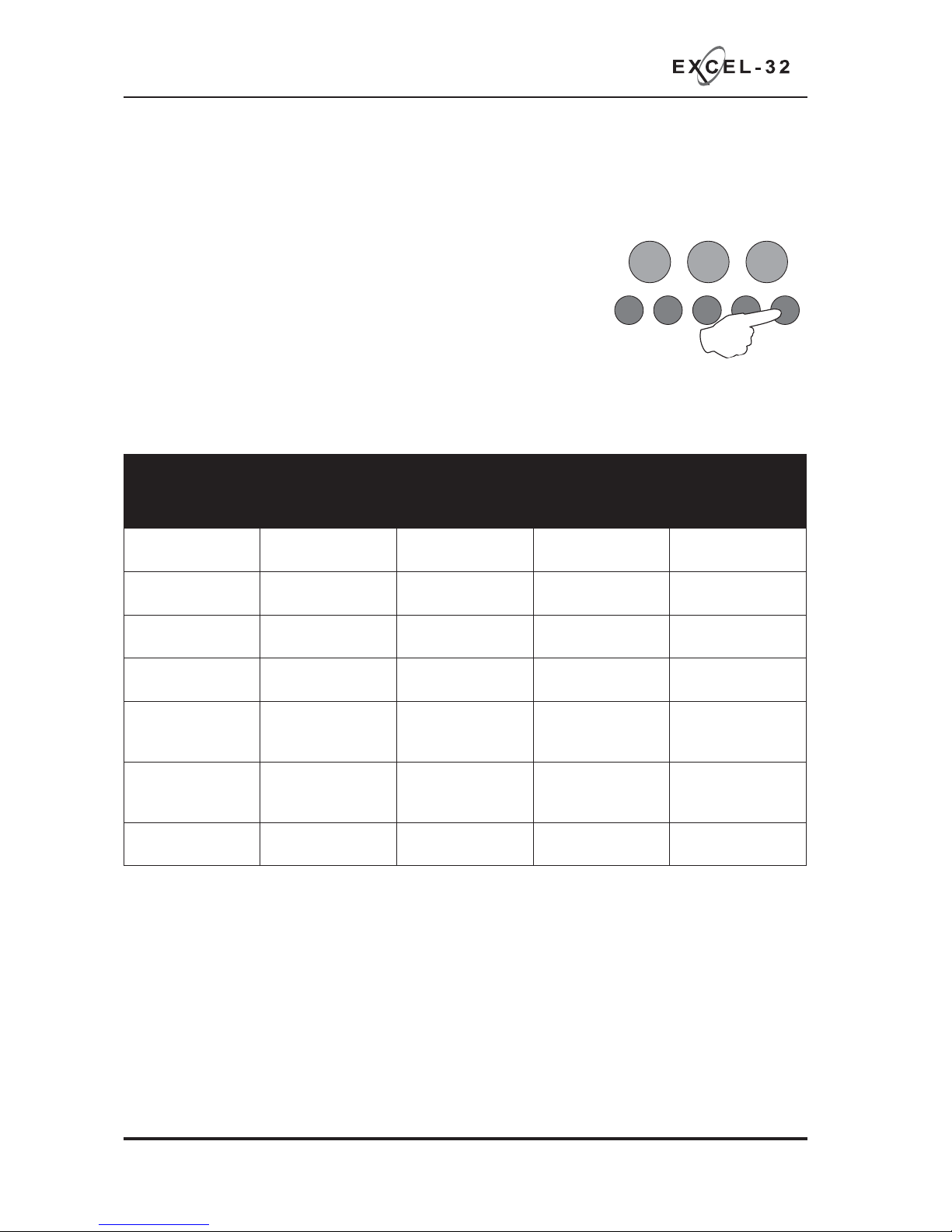
FAULT DIAGNOSIS
If the panel has detected a fault on the system the General Fault LED will be illuminated and the internal
fault buzzer will sound. Secondary LEDs will also be illuminated depending on the location of the fault.
Pressing and holding the ENTER button will reveal more detailed
information about the loction and type of fault.
This function will not work if the panel is in a fi re condition. If no faults
exist pressing the ENTER button will have no effect.
This function is operational only when controls are not active.
The following table shows details of the indications in fault diagnosis mode:
RESOUND SILENCE RESET
ENTER
1234
Disable
Mode
Tes t
Mode
Mute
Buzzer
Tes t
Lamps
LED Indicator
& State before
pressing ENTER
LED Pulsing after
pressing ENTER
LED Steady after
pressing ENTER
LED Off or Slow
Pulse after
pressing ENTER
Location
Zone 1 Fire LED
(of
f)
Sounder circuit 1
short circuit
Sounder circuit 1
open circuit
OK Main PCB SNDR 1
Zone 2 Fire LED
(off)
Sounder circuit 2
short circuit
Sounder circuit 2
open circuit
OK Main PCB SNDR 2
Zone 3 Fire LED
(off)
Sounder circuit 3
short circuit
Sounder circuit 3
open circuit
OK Main PCB SNDR 3
Zone 4 Fire LED
(off)
Sounder circuit 4
short circuit
Sounder circuit 4
open circuit
OK Main PCB SNDR 4
Zone 1 - 32 Fault/
Disabled/Test LED
(pulsing)
Zone # short
circuit
Zone # open
circuit
(slow pulse)
Zone # detector
removed
Main PCB Zones
1 - 32
Zone 1 - 32 Fault/
Disabled/Test LED
(steady)
N/A N/A Zone # disabled or
in test mode
Power Supply
Fault LED (pulsing)
Mains failure Battery failure or
high impedance
Voltage fault Main PCB
www.acornfiresecurity.com
www.acornfiresecurity.com
Page 17

XL32 Quick Start Guide Approved Document Ref: UI-XL32-02 Issue 1.0
15
OPERATING
FUNCTIONALITY DURING A SYSTEM FAULT
A system fault is indicated when a processor controlling a function in the panel has a watchdog time out
or processor failure. In the event of a system fault the particular board affected may not be functional. The
following indications may be observed.
Display Board
System Fault LED only continous and continous buzzer sound. Display board, TPCA10 is halted and
no other indication or control is possible. Fault relay and fault output are activated. If a fi re occurs alarm
sounders and outputs will still function.
Main Board
System Fault LED continous and General Fault LED pulsing and continous buzzer sound. Main board is
halted. Fault relay is activated.
Repeater Comms Board
System Fault LED continous and General Fault LED pulsing and Repeater Fault LED continous. The
Comms Board TPCA05 is halted. Fault relay and output are active, and repeater panels will cease to
function. Fire alarms can still be detected and controlled by the panel.
Power Supply Board
System Fault LED pulsing, General Fault LED pulsing, PSU Fault LED pulsing, continous buzzer sound
(mutable) and fault relay activated. Mains or battery power will still operate the panel. Batteries will not be
charging. Indications will remain until the fault is rectifi ed and the panel is reset.
System Fault recovery
System Fault LED pulsing and General Fault LED pulsing along with a pulsed buzzer (fault tone) a system
fault has occurred and the affected board has recovered. The indication will remain until the panel is reset.
www.acornfiresecurity.com
www.acornfiresecurity.com
Page 18

DDATE &
DEVICE TESTED &
LOCATION
COMMENTS
(IF ANY)
INITIALS OF
TESTER
TIME OF TEST
SCHEDULE OF TESTING
This Section To Be Used To Record ALL Weekly Tests Of The Fire Alarm System
XL32 Quick Start Guide Approved Document Ref: UI-XL32-02 Issue 1.0
16
www.acornfiresecurity.com
www.acornfiresecurity.com
Page 19

DDATE &
DEVICE TESTED &
LOCATION
COMMENTS
(IF ANY)
INITIALS OF
TESTER
TIME OF TEST
SCHEDULE OF TESTING
This Section To Be Used To Record ALL Weekly Tests Of The Fire Alarm System
XL32 Quick Start Guide Approved Document Ref: UI-XL32-02 Issue 1.0
17
www.acornfiresecurity.com
www.acornfiresecurity.com
Page 20

DDATE &
DEVICE TESTED &
LOCATION
COMMENTS
(IF ANY)
INITIALS OF
TESTER
TIME OF TEST
SCHEDULE OF TESTING
This Section To Be Used To Record ALL Weekly Tests Of The Fire Alarm System
XL32 Quick Start Guide Approved Document Ref: UI-XL32-02 Issue 1.0
18
www.acornfiresecurity.com
www.acornfiresecurity.com
Page 21

DDATE &
DEVICE TESTED &
LOCATION
COMMENTS
(IF ANY)
INITIALS OF
TESTER
TIME OF TEST
SCHEDULE OF TESTING
This Section To Be Used To Record ALL Weekly Tests Of The Fire Alarm System
XL32 Quick Start Guide Approved Document Ref: UI-XL32-02 Issue 1.0
19
www.acornfiresecurity.com
www.acornfiresecurity.com
Page 22

FALSE ALARMS, FAULTS & ENGINEERS VISITS
XL32 Quick Start Guide Approved Document Ref: UI-XL32-02 Issue 1.0
20
Fault/Reason For
Call-Out
Action Taken Date Work Completed Engineer’s Details
www.acornfiresecurity.com
www.acornfiresecurity.com
Page 23

FALSE ALARMS, FAULTS & ENGINEERS VISITS
XL32 Quick Start Guide Approved Document Ref: UI-XL32-02 Issue 1.0
21
Fault/Reason For
Call-Out
Action Taken Date Work Completed Engineer’s Details
www.acornfiresecurity.com
www.acornfiresecurity.com
Page 24

FALSE ALARMS, FAULTS & ENGINEERS VISITS
XL32 Quick Start Guide Approved Document Ref: UI-XL32-02 Issue 1.0
22
Fault/Reason For
Call-Out
Action Taken Date Work Completed Engineer’s Details
www.acornfiresecurity.com
www.acornfiresecurity.com
Page 25

USER INSTRUCTIONS
RESOUND SILENCE RESET
ENTER
1234
Disable
Mode
Tes t
Mode
Mute
Buzzer
Tes t
Lamps
RESOUND SILENCE RESET
ENTER
1234
Disable
Mode
Tes t
Mode
Mute
Buzzer
Tes t
Lamps
RESOUND SILENCE RESET
ENTER
1234
Disable
Mode
Tes t
Mode
Mute
Buzzer
Tes t
Lamps
If an alarm condition is present YOU MUST FOLLOW YOUR NORMAL FIRE DRILL PROCEDURES.
A responsible person should then:-
1.
1.
Check the control panel to see which area or zone has caused the system to go into alarm. This will
Check the control panel to see which area or zone has caused the system to go into alarm. This will
be indicated by a pulsing red LED on the front of the control panel.
be indicated by a pulsing red LED on the front of the control panel.
2.
2.
Go to the area which has caused the alarm to check if a fi re exists.
Go to the area which has caused the alarm to check if a fi re exists.
3.
3.
Only when it is safe to do so should the alarms be silenced. Activate the controls by turning the key
Only when it is safe to do so should the alarms be silenced. Activate the controls by turning the key
switch or by entering the four digit code (see Activate Controls in the OPERATING section) and press
switch or by entering the four digit code (see Activate Controls in the OPERATING section) and press
the (blue) SILENCE ALARMS button (fi g 1). To sound the alarms again press the (red) RESOUND
the (blue) SILENCE ALARMS button (fi g 1). To sound the alarms again press the (red) RESOUND
button (fi g 2).
button (fi g 2).
4.
4.
In the event of a false alarm look for the device that has caused the alarm. A detector will have a red
In the event of a false alarm look for the device that has caused the alarm. A detector will have a red
LED lit, or check to see if a call point glass is broken (if so replace the glass or call an engineer).
LED lit, or check to see if a call point glass is broken (if so replace the glass or call an engineer).
5.
5.
When fully satisfi ed that there is no fi re, return to the control panel and press the (green) RESET
When fully satisfi ed that there is no fi re, return to the control panel and press the (green) RESET
button, (fi g 3). The panel display should return to normal and only the green SUPPLY HEALTHY LED
button, (fi g 3). The panel display should return to normal and only the green SUPPLY HEALTHY LED
should be lit on the control panel.
should be lit on the control panel.
fi g 1 fi g 2
fi g 3
If the system continues to false alarm, call an engineer
If the system continues to false alarm, call an engineer
Fault Condition
Fault Condition
If a buzzer is sounding in the control panel but the sounders or bells are not ringing, then there is either a
If a buzzer is sounding in the control panel but the sounders or bells are not ringing, then there is either a
fault on the system, or zones / sounders have been disabled. CALL AN ENGINEER
fault on the system, or zones / sounders have been disabled. CALL AN ENGINEER
The internal fault buzzer can be silenced by pressing MUTE BUZZER (button 3 on the keypad). DO
The internal fault buzzer can be silenced by pressing MUTE BUZZER (button 3 on the keypad). DO
NOT RESET THE SYSTEM UNTIL AN ENGINEER HAS INVESTIGATED THE FAULT.
NOT RESET THE SYSTEM UNTIL AN ENGINEER HAS INVESTIGATED THE FAULT.
Tear Here
www.acornfiresecurity.com
www.acornfiresecurity.com
Page 26

www.acornfiresecurity.com
www.acornfiresecurity.com
 Loading...