

Page 1
R
2
PCS
Working with the Haemonetics® PCS®2
- Operation Manual -
0123
Printed in France
Haemonetics Corporation
400 Wood Road
Braintree, MA, 02184, USA P/N 85266-30, Manual revision: A
©2002, Haemonetics International. All rights reserved. April 2002
Page 2

Page 3

Preface iii
CONSUMER INFORMATION
Proprietary rights The contents of this manual are property of the Haemonetics Corporation.
Haemonetics
ration. Any information or descriptions contained in this manual may not be
reproduced and released to any of the general public, or used in conjunction with
any professional instruction without written consent of Haemonetics Corpo-
ration, USA. Please direct any written inquiries to the appropriate address:
®
and PCS®2 are registered trademarks of the Haemonetics Corpo-
International Headquarters
Haemonetics S.A.
Signy Center, P.O. Box 262
CH-1274 Signy 2 Switzerland
Tel. +41-22-363-9011
Fax +41-22-363-9054
Corporate Headquarters
Haemonetics Corporation
400 Wood Road
Braintree, MA, 02184, USA
Tel. +1-781-848-7100
Fax +1-781-356-3558
Legal disclaimer This manual is intended for use as a guide, uniquely for material as supplied by
the Haemonetics Corporation. It provides the operator with necessary information to safely carry out specific procedures and satisfactorily maintain Haemonetics-produced equipment. The manual is to be used in conjunction with
instruction and training as supplied by qualified Haemonetics personnel.
Haemonetics guarantees its products when correctly used by a properly trained
operator. Any failure to respect the procedures as described could result in
impaired function of the equipment, as well as in injury to the operator and/or
patient /donor. Haemonetics accepts no responsibility for problems resulting
from failure to comply with prescriptions as outlined by the company. Any modifications estimated as necessary by the customer should be evaluated by a
Haemonetics Clinical Specialist.
Safe utilization of Haemonetics material and equipment requires the operator to
correctly handle and dispose of blood-contaminated material. The operator of
any Haemonetics equipment must understand and implement the local policies
and standard operating procedures concerning the handling of blood-contaminated material, as well as blood products.
It remains solely the responsibility of the customer to fully assess and ensure the
safety of any products obtained from Haemonetics prescribed procedures, prior
to further application or use. Haemonetics declines any responsibility for choices
made by the consumer concerning the utilization of products and by-products.
In addition, it is the responsibility of the apheresis center using Haemonetics
equipment and material to inform the donor about the risks involved with any
apheresis procedure. Prior to initiating any procedure, the apheresis center is
responsible to verify that the donor understands these risks and consents to the
procedure.
P/N 85266-30, Manual revision: A
Page 4

iv Preface
Haemonetics worldwide locations
Haemonetics Asia Inc.
Taiwan Branch
26F-1, No. 102 Roosevelt Road Sec. 2
Taipei, Taiwan
Tel. +886-2-2369-0722
Fax +886-2-2364-3698
Haemonetics GesmbH
Handelsges.m.b.H.
Berlagasse 45/B2-02
A-1210 Wien, Austria
Tel. +43-1-294-29-00
Fax +43-1-294-29-05
Haemonetics Belgium NV
Leuvensesteenweg 542-BP. 14
Planet II Complex
B-1930 Zaventem, Belgium
Tel. +32-2-720-7484
Fax +32-2-720-7155
Haemonetics BV
C/O CITCO - WTC, PB 7241
Strawinskylaan 1725
1007 JE Amsterdam
The Netherlands
Tel. +31-35-602-3425
Fax +31-35-602-4198
Haemonetics Medical Devices
(Shanghai) International
Trading Co. Ltd.
Room 28032, Shanghai HSBC Tower
101 Yin Cheng East Road
Shangai 200120, PRC
Tel. +86-21-506-63366
Fax +86-21-684-13688
Haemonetics CZ, spol. S.r.o
Ptašínského C.8
60200 Brno, Czech Republic
Tel. +42-05-412-122400
Fax +42-05-412-122399
Haemonetics France S.A.R.L.
46 bis, rue Pierre Curie
Z.I. Les Gatines
F-78370 Plaisir, France
Tel. +33-1-30-81-4141
Fax +33-1-30-81-4130
Haemonetics GmbH
Rohrauerstrasse 72
D-81477 München, Germany
Tel. +49-89-785-8070
Fax +49-89-780-9779
Haemonetics Hong Kong Ltd.
Suite 1314, Two Pacific Place
88 Queensway, Hong Kong
Tel. +852-286-89218
Fax +852-280-14380
Haemonetics Italia S.R.L.
Via Donizetti, 30
20020 Lainate (MI), Italy
Tel. +39-2-935-70113
Fax +39-2-935-72132
Haemonetics Japan K.K.
Kyodo Building 3F
16, Ichiban-cho, Chiyoda-ku
Tokyo, Japan, 102-0082
Tel. +81-3-3237-7260
Fax +81-3-3237-7330
Haemonetics Scandinavia AB
Beta Huset, Ideon
Scheelegatan 17
S-223 70 Lund, Sweden
Tel. +46-46-286-2320
Fax +46-46-286-2321
P/N 85266-30, Manual revision: A
Page 5

Preface v
Haemonetics (UK) Ltd.
Beechwood House
Beechwood Estate
Elmete Lane, Roundhay
Leeds LS8 2LQ, United Kingdom
Tel. +44-113-273-7711
Fax +44-113-273-4055
Haemonetics S.A.
Signy Centre
P. O. B o x 2 6 2
CH-1274 Signy 2, Switzerland
Tel. +41-22-363- 9011
Fax +41-22-363- 9054
P/N 85266-30, Manual revision: A
Page 6

Page 7

Table of Contents
Chapter 1 Explaining General Information
PROVIDING AN OVERVIEW . . . . . . . . . . . . . . . . . . . . . . . . . . . . . . . . . . . . 1-2
What is apheresis technology? . . . . . . . . . . . . . . . . . . . . . . . . . . . . . . . 1-2
What is the purpose of this manual? . . . . . . . . . . . . . . . . . . . . . . . . . . . 1-2
What is the Haemonetics Plasma Collection System 2?. . . . . . . . . . . . . 1-3
What are the characteristics and features of the PCS2? . . . . . . . . . . . . . 1-3
What are the special features of the PCS2? . . . . . . . . . . . . . . . . . . . . . . 1-4
What is required to perform a procedure? . . . . . . . . . . . . . . . . . . . . . . . 1-4
UNDERSTANDING THE USE OF SYMBOLS . . . . . . . . . . . . . . . . . . . . . . . . 1-5
Symbols found in this document . . . . . . . . . . . . . . . . . . . . . . . . . . . . . . 1-5
Symbols found on the device . . . . . . . . . . . . . . . . . . . . . . . . . . . . . . . . 1-5
Symbols found on disposable packaging. . . . . . . . . . . . . . . . . . . . . . . . 1-8
LISTING DEVICE SPECIFICATIONS . . . . . . . . . . . . . . . . . . . . . . . . . . . . . . . 1-9
Chapter 2 Describing the PCS2 Device Components
PRESENTING THE PCS2 DEVICE COMPONENTS . . . . . . . . . . . . . . . . . . . 2-3
DESCRIBING THE CENTRIFUGE SYSTEM . . . . . . . . . . . . . . . . . . . . . . . . . 2-4
System-sealing mechanism . . . . . . . . . . . . . . . . . . . . . . . . . . . . . . . . . 2-5
Centrifuge well . . . . . . . . . . . . . . . . . . . . . . . . . . . . . . . . . . . . . . . . . . 2-6
Centrifuge base . . . . . . . . . . . . . . . . . . . . . . . . . . . . . . . . . . . . . . . . . . 2-6
DESCRIBING THE PCS2 CABINET COMPONENTS . . . . . . . . . . . . . . . . . . 2-7
Optical line Sensor . . . . . . . . . . . . . . . . . . . . . . . . . . . . . . . . . . . . . . . 2-7
Weigher . . . . . . . . . . . . . . . . . . . . . . . . . . . . . . . . . . . . . . . . . . . . . . . 2-7
Pumps. . . . . . . . . . . . . . . . . . . . . . . . . . . . . . . . . . . . . . . . . . . . . . . . . 2-8
Valves. . . . . . . . . . . . . . . . . . . . . . . . . . . . . . . . . . . . . . . . . . . . . . . . . 2-9
Donor flow lights . . . . . . . . . . . . . . . . . . . . . . . . . . . . . . . . . . . . . . . 2-10
Air detectors . . . . . . . . . . . . . . . . . . . . . . . . . . . . . . . . . . . . . . . . . . . 2-11
Pressure monitors . . . . . . . . . . . . . . . . . . . . . . . . . . . . . . . . . . . . . . . 2-13
Blood filter holder. . . . . . . . . . . . . . . . . . . . . . . . . . . . . . . . . . . . . . . 2-14
Solution-bag poles (2) . . . . . . . . . . . . . . . . . . . . . . . . . . . . . . . . . . . . 2-14
Power entry module . . . . . . . . . . . . . . . . . . . . . . . . . . . . . . . . . . . . . 2-15
Power cord . . . . . . . . . . . . . . . . . . . . . . . . . . . . . . . . . . . . . . . . . . . . 2-15
Pressure cuff . . . . . . . . . . . . . . . . . . . . . . . . . . . . . . . . . . . . . . . . . . . 2-15
Biohazard waste bag . . . . . . . . . . . . . . . . . . . . . . . . . . . . . . . . . . . . . 2-15
Communication box/data card (optional) . . . . . . . . . . . . . . . . . . . . . 2-16
Bar code reader (optional). . . . . . . . . . . . . . . . . . . . . . . . . . . . . . . . . 2-16
P/N 85266-30, Manual revision: A
Page 8

viii Table of Contents
DESCRIBING THE PCS2 CONTROL PANEL . . . . . . . . . . . . . . . . . . . . . . . 2-17
Display screen . . . . . . . . . . . . . . . . . . . . . . . . . . . . . . . . . . . . . . . . . . 2-17
Mode control keys . . . . . . . . . . . . . . . . . . . . . . . . . . . . . . . . . . . . . . . 2-19
Protocol key. . . . . . . . . . . . . . . . . . . . . . . . . . . . . . . . . . . . . . . . . . . . 2-19
Pump control keys . . . . . . . . . . . . . . . . . . . . . . . . . . . . . . . . . . . . . . . 2-20
Programming keys . . . . . . . . . . . . . . . . . . . . . . . . . . . . . . . . . . . . . . . 2-20
Cuff key . . . . . . . . . . . . . . . . . . . . . . . . . . . . . . . . . . . . . . . . . . . . . . . 2-21
Valve control keys . . . . . . . . . . . . . . . . . . . . . . . . . . . . . . . . . . . . . . . 2-21
Chapter 3 Maintaining the PCS2 Equipment
CLEANING PROCEDURES . . . . . . . . . . . . . . . . . . . . . . . . . . . . . . . . . . . . . 3-2
Cabinet, control panel and valves . . . . . . . . . . . . . . . . . . . . . . . . . . . . 3-2
Pressure monitors. . . . . . . . . . . . . . . . . . . . . . . . . . . . . . . . . . . . . . . . . 3-3
Air detectors . . . . . . . . . . . . . . . . . . . . . . . . . . . . . . . . . . . . . . . . . . . . 3-3
Optical sensors . . . . . . . . . . . . . . . . . . . . . . . . . . . . . . . . . . . . . . . . . . 3-3
Fluid detector. . . . . . . . . . . . . . . . . . . . . . . . . . . . . . . . . . . . . . . . . . . . 3-4
Centrifuge components . . . . . . . . . . . . . . . . . . . . . . . . . . . . . . . . . . . . 3-4
Pumps . . . . . . . . . . . . . . . . . . . . . . . . . . . . . . . . . . . . . . . . . . . . . . . . . 3-5
Filter screens . . . . . . . . . . . . . . . . . . . . . . . . . . . . . . . . . . . . . . . . . . . . 3-5
Barcode reader. . . . . . . . . . . . . . . . . . . . . . . . . . . . . . . . . . . . . . . . . . . 3-5
CUSTOMER SERVICE . . . . . . . . . . . . . . . . . . . . . . . . . . . . . . . . . . . . . . . . . 3-6
Clinical training . . . . . . . . . . . . . . . . . . . . . . . . . . . . . . . . . . . . . . . . . . 3-6
Field service. . . . . . . . . . . . . . . . . . . . . . . . . . . . . . . . . . . . . . . . . . . . . 3-6
Returned Goods Authorization system . . . . . . . . . . . . . . . . . . . . . . . . . 3-6
HAEMONETICS® CLEANING AND MAINTENANCE RECORD . . . . . . . . . 3-8
Chapter 4 Ensuring Safety and Quality for a PCS2 Procedure
HANDLING THE PCS2 EQUIPMENT . . . . . . . . . . . . . . . . . . . . . . . . . . . . . 4-2
Storing the PCS2 device and material. . . . . . . . . . . . . . . . . . . . . . . . . . 4-2
Inspecting the material . . . . . . . . . . . . . . . . . . . . . . . . . . . . . . . . . . . . . 4-2
PREVENTING PROBLEMS DURING A PCS2 PROCEDURE. . . . . . . . . . . . . 4-3
Understanding the risk of hemolysis. . . . . . . . . . . . . . . . . . . . . . . . . . . 4-3
Avoiding the consequences of flow restriction . . . . . . . . . . . . . . . . . . . 4-3
Avoiding bowl misalignment . . . . . . . . . . . . . . . . . . . . . . . . . . . . . . . . 4-4
Avoiding overheating due to mechanical situations . . . . . . . . . . . . . . . 4-4
Controlling for Red Cell Overrun . . . . . . . . . . . . . . . . . . . . . . . . . . . . . 4-4
WARNINGS FOR THE OPERATOR. . . . . . . . . . . . . . . . . . . . . . . . . . . . . . . 4-5
Electrical shock hazards . . . . . . . . . . . . . . . . . . . . . . . . . . . . . . . . . . . . 4-5
Leakage current control . . . . . . . . . . . . . . . . . . . . . . . . . . . . . . . . . . . 4-5
Mechanical hazards/rotating parts . . . . . . . . . . . . . . . . . . . . . . . . . . . . 4-5
Power outlet connection . . . . . . . . . . . . . . . . . . . . . . . . . . . . . . . . . . . 4-5
Communicable disease precautions . . . . . . . . . . . . . . . . . . . . . . . . . . . 4-6
P/N 85266-30, Manual revision: A
Page 9

Chapter 1
Explaining General Information
PROVIDING AN OVERVIEW . . . . . . . . . . . . . . . . . . . . . . . . . . . . . . . . . . . 1-2
What is apheresis technology? . . . . . . . . . . . . . . . . . . . . . . . . . . . . . . . 1-2
What is the purpose of this manual? . . . . . . . . . . . . . . . . . . . . . . . . . . . 1-2
What is the Haemonetics Plasma Collection System 2? . . . . . . . . . . . . 1-3
What are the characteristics and features of the PCS2? . . . . . . . . . . . . . 1-3
What are the special features of the PCS2? . . . . . . . . . . . . . . . . . . . . . . 1-4
What is required to perform a procedure?. . . . . . . . . . . . . . . . . . . . . . . 1-4
UNDERSTANDING THE USE OF SYMBOLS. . . . . . . . . . . . . . . . . . . . . . . . 1-5
Symbols found in this document. . . . . . . . . . . . . . . . . . . . . . . . . . . . . . 1-5
Symbols found on the device . . . . . . . . . . . . . . . . . . . . . . . . . . . . . . . . 1-5
Symbols found on disposable packaging . . . . . . . . . . . . . . . . . . . . . . . 1-8
LISTING DEVICE SPECIFICATIONS . . . . . . . . . . . . . . . . . . . . . . . . . . . . . . . 1-9
P/N 85266-30, Manual revision: A
Page 10

1-2 Explaining General Information
PROVIDING AN OVERVIEW
What is apheresis technology?
What is the purpose of this manual?
Apheresis is the general term used to describe the separation, selective removal
and collection of one or more of the individual components which together form
whole blood. This term can be subdivided into two categories:
z Cytapheresis: selective removal of one or more of the formed, cellular
components of whole blood. These elements include erythrocytes,
thrombocytes and leukocytes.
z Plasmapheresis: selective removal of plasma, the liquid suspension me-
dium of blood. Plasma contains elements referred to as fractionable
components, such as clotting proteins and immunoglobulins.
Apheresis technology permits:
z The collection and separation of whole blood.
z The selective removal and collection of specific components.
z The subsequent return of the non-selected components to the donor
or patient.
This manual is intended to supply anyone involved in using Haemonetics equipment with the essential tool for safe and successful operation – information.
Using this tool of information, the operator can acquire knowledge to be applied
throughout all levels of operating experience. This body of information should be
consulted whenever necessary, starting from the initial contact with Haemonetics
technology to attain:
P/N 85266-30, Manual revision: A
z An awareness of the purpose of the device and the implications of its col-
lection procedures for the donor and the apheresis center.
z An understanding of how to safely operate the Haemonetics system, cor-
rectly install the appropriate disposable material, and troubleshoot any
difficulties.
z An ability to consistently apply the principles behind safe operation,
proper maintenance and correct handling to ensure optimal, quality
apheresis results.
Page 11

Explaining General Information 1-3
What is the
Haemonetics
Plasma
Collection
System 2?
What are the characteristics and features of the PCS2?
Using updated apheresis technology, Haemonetics has produced the PCS2 - a
compact, lightweight plasmapheresis system which is as easy and safe to use as
it is technologically advanced.
The PCS2 automated apheresis technology provides the operator with a
maximum degree of flexibility in any type of plasmapheresis location. The
plasma collected may be designated for use in therapeutic transfusion. It may also
be conserved, used as source plasma and subsequently fractionated into plasmaderived products.
The PCS2 is appropriately called a Plasma Collection System because it consists
of distinctive parts which collectively function as a whole system to produce a
designated final product:
z The automated plasmapheresis device developed by Haemonetics
called the PCS2.
z The process designed by Haemonetics to gather plasma from a donor
called a collection procedure.
z The single-use collection material manufactured by Haemonetics called
a disposable set.
Once the operator has initiated a PCS2 procedure, plasma collection will
proceed automatically. The appropriate amount of anticoagulant solution will be
mixed in the disposable tubing with whole blood from the donor. This anticoagulated blood will be drawn into a disposable collection bowl and separated by
centrifugal force into its various components.
When the bowl reaches its collection capacity, the plasma component will exit
the bowl and be directed into a plasma collection container for conservation.
Non-selected blood components will be returned to the donor. This cycle will be
repeated until the desired amount of plasma is collected.
The choice of the disposable collection material will depend on the desired
collection product. The PCS2 technology also provides the operator with the
option to infuse saline solution along with the blood components to the donor at
different points of a procedure, depending on the type of disposable bowl in use.
Haemonetics has designed the PCS2 technology with a degree of automation
which permits the operator to interact with the device. The operator should
remain attentive to the display screen messages while monitoring the status of the
donor. It is possible to modify certain aspects of the collection procedures, based
on the needs and requirements of the individual donor and the selected material.
P/N 85266-30, Manual revision: A
Page 12

1-4 Explaining General Information
What are the special features of the PCS2?
What is required to perform a procedure?
Haemonetics has incorporated advanced technological features into the portable
PCS2 design. Examples of these features, which ensure safety for the donor and
permit efficient time-management for the operator, are:
z Self-loading pumps.
z Advanced optical sensors.
z Donor-line tubing pressure monitor.
z Communication data box or internal data card.
z Barcode reader.
PCS2 collection procedures are quick and simple to perform. The following
material is required to perform a PCS2 procedure:
z A PCS2 disposable set designed for the selected procedure.
z Venipuncture materials and hemostats.
z Appropriate anticoagulant solution.
z 0.9% normal saline (optional).
The operator will need to:
Î Install the appropriate disposable set.
Î Modify any settings if necessary.
Î Perform a single venous puncture, prior to initiating a procedure.
Plasma collection will proceed automatically until the end-collection target has
been reached.
P/N 85266-30, Manual revision: A
Page 13
Explaining General Information 1-5
UNDERSTANDING THE USE OF SYMBOLS
Symbols found in this document
Symbols found on the device
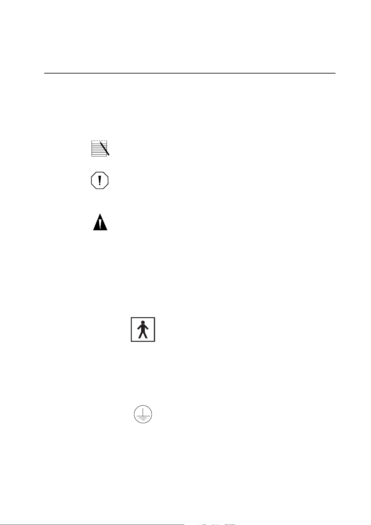
The terms note, caution and warning are used in this manual with the following
symbols to emphasize certain details for the operator.
Note: Provides useful information regarding a procedure or operating technique when using Haemonetics material.
Caution: Advises the operator against initiating an action or creating a situation which could result in damage to equipment, or impair the quality of the
by-products; personal injury is unlikely.
Warning: Advises the operator against initiating an action or creating a situation which could result in serious personal injury to either the donor or
the operator.
The descriptions of the following symbols are based on information provided in
the following documents:
z IEC Standard 60601-1, Medical Electrical Equipment,
Part 1: General requirements for safety.
z IEC Standard 60417-1, Graphical symbols for use on equipment,
Part 1: Overview and application.
Type BF applied part
This symbol indicates that the applied portion (i.e. the part which comes in
contact with the donor) of the device is electrically isolated. The device has
an internal electrical power source providing adequate protection against
electrical shock, in particular pertaining to acceptable leakage current and
the reliability of the protective earth connection.
Protective earth (ground)
Used to identify any terminal intended for connection to an external
conductor, for protection against electrical shock in case of a fault.
P/N 85266-30, Manual revision: A
Page 14

1-6 Explaining General Information
~ Alternating current
Used to indicate on the rating plate that the device is suitable for alternating
current only.
Fuse symbol
Used to identify fuse boxes or the location of a fuse box.
Power OFF
Position of the main power switch indicating disconnection from the mains.
Power ON
Position of the main power switch indicating connection to the mains.
IPX1 Protection against ingress of liquid
Indicates that the enclosure of the device is designed to provide a specified
degree of protection against harmful ingress of water or liquid into the equipment (under applicable conditions).
Attention (Consult accompanying documents)
Non-ionizing electromagnetic radiation
Used to specify RF transmission for data communication.
P/N 85266-30, Manual revision: A
Page 15

Explaining General Information 1-7
The following symbols have been designed for devices manufactured
by Haemonetics:
Bar-code reader connection
RS232 connection
RS232 connection with power to one pin
Pressure cuff connection
P/N 85266-30, Manual revision: A
Page 16
1-8 Explaining General Information
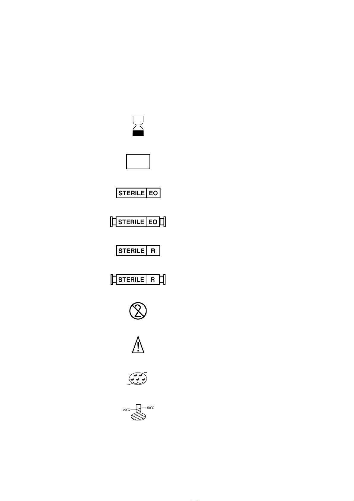
Symbols found on disposable packaging
The following symbols are used by Haemonetics on disposable set packaging.
REF
LOT
CATALOG NUMBER
EXPIRATION DATE
Lot Number
Sterilized by exposure to Ethylene Oxide
Fluid path STERILE by exposure to Ethylene Oxide
8%
Sterilized by exposure to Gamma irradiation
Fluid path STERILE by exposure to Gamma irradiation
DO NOT REUSE
Caution: consult operator manual for instructions
80%
Storage conditions, humidity level
Storage conditions, temperature level
P/N 85266-30, Manual revision: A
Page 17

Explaining General Information 1-9
LISTING DEVICE SPECIFICATIONS
The approximate weight and dimensions of the PCS2 device are as follows:
Values
Characteristics
Height 63 cm 44 cm
Width 55 cm
Depth 55 cm 32 cm
Depth with communication box 55 cm 37 cm
Weight 26.4 kg
Weight with communication box 27.4 kg
Cabinet
cover open
Cabinet
cover closed
The following environmental conditions should be respected pertaining to operation and storage of the PCS2 device:
Conditions Values
Ambient operating temperature +18° C to +27° C
Tested storage temperature 0° C to + 40° C
Storage humidity level Maximum relative humidity rate of 90%,
non-condensing
The electrical specifications for operating the PCS2 device are as follows:
Characteristics Values
Input voltage 230 VAC ± 10% 110 VAC ± 10%
Operating current ~1.9 A ~ 2.6 A
Fuse rating F2.5 A @ 250 V F5.0 A @ 250 V
Operating frequency range 50 - 60 Hz 50 - 60 Hz
Maximum leakage current 500 µA 100 µA
(relative to input voltage)
Note: Haemonetics will regulate the proper voltage setting upon installation.
The power source used must be properly grounded.
P/N 85266-30, Manual revision: A
Page 18

1-10 Explaining General Information
Caution: The PCS2 device must be operated in an environment compatible to the
requirements of the IEC 60601-1-2 Standard, Electromagnetic compatibility.
Mobile RF communication equipment not approved by Haemonetics and portable communication equipment can affect the PCS2 device. Any accessories and
cables not approved by Haemonetics used in conjunction with the device may
increase hazards and influence compatibility with EMC requirements. Therefore,
non-approved accessories and cables must not be used.
In addition, the PCS2 device and accessories must not be placed directly adjacent to, or top of other equipment, unless specifically approved by Haemonetics.
P/N 85266-30, Manual revision: A
Page 19

Chapter 2
Describing the PCS2 Device Components
PRESENTING THE PCS2 DEVICE COMPONENTS . . . . . . . . . . . . . . . . . . . . 2-3
DESCRIBING THE CENTRIFUGE SYSTEM . . . . . . . . . . . . . . . . . . . . . . . . . . 2-4
System-sealing mechanism . . . . . . . . . . . . . . . . . . . . . . . . . . . . . . . . . . 2-5
Centrifuge well . . . . . . . . . . . . . . . . . . . . . . . . . . . . . . . . . . . . . . . . . . . 2-6
Centrifuge base. . . . . . . . . . . . . . . . . . . . . . . . . . . . . . . . . . . . . . . . . . . 2-6
DESCRIBING THE PCS2 CABINET COMPONENTS. . . . . . . . . . . . . . . . . . . 2-7
Optical line Sensor . . . . . . . . . . . . . . . . . . . . . . . . . . . . . . . . . . . . . . . . 2-7
Weigher . . . . . . . . . . . . . . . . . . . . . . . . . . . . . . . . . . . . . . . . . . . . . . . . 2-7
Pumps . . . . . . . . . . . . . . . . . . . . . . . . . . . . . . . . . . . . . . . . . . . . . . . . . 2-8
Valves. . . . . . . . . . . . . . . . . . . . . . . . . . . . . . . . . . . . . . . . . . . . . . . . . . 2-9
Donor flow lights . . . . . . . . . . . . . . . . . . . . . . . . . . . . . . . . . . . . . . . . 2-10
Air detectors . . . . . . . . . . . . . . . . . . . . . . . . . . . . . . . . . . . . . . . . . . . . 2-11
Pressure monitors . . . . . . . . . . . . . . . . . . . . . . . . . . . . . . . . . . . . . . . . 2-13
Blood filter holder . . . . . . . . . . . . . . . . . . . . . . . . . . . . . . . . . . . . . . . 2-14
Solution-bag poles (2). . . . . . . . . . . . . . . . . . . . . . . . . . . . . . . . . . . . . 2-14
Power entry module . . . . . . . . . . . . . . . . . . . . . . . . . . . . . . . . . . . . . . 2-15
Power cord. . . . . . . . . . . . . . . . . . . . . . . . . . . . . . . . . . . . . . . . . . . . . 2-15
Pressure cuff . . . . . . . . . . . . . . . . . . . . . . . . . . . . . . . . . . . . . . . . . . . . 2-15
Biohazard waste bag . . . . . . . . . . . . . . . . . . . . . . . . . . . . . . . . . . . . . 2-15
Communication box/data card (optional) . . . . . . . . . . . . . . . . . . . . . . 2-16
Bar code reader (optional) . . . . . . . . . . . . . . . . . . . . . . . . . . . . . . . . . 2-16
DESCRIBING THE PCS2 CONTROL PANEL . . . . . . . . . . . . . . . . . . . . . . . 2-17
Display screen . . . . . . . . . . . . . . . . . . . . . . . . . . . . . . . . . . . . . . . . . . 2-17
Mode control keys . . . . . . . . . . . . . . . . . . . . . . . . . . . . . . . . . . . . . . . 2-19
Protocol key . . . . . . . . . . . . . . . . . . . . . . . . . . . . . . . . . . . . . . . . . . . . 2-19
Pump control keys . . . . . . . . . . . . . . . . . . . . . . . . . . . . . . . . . . . . . . . 2-20
Programming keys . . . . . . . . . . . . . . . . . . . . . . . . . . . . . . . . . . . . . . . 2-20
Cuff key . . . . . . . . . . . . . . . . . . . . . . . . . . . . . . . . . . . . . . . . . . . . . . . 2-21
Valve control keys . . . . . . . . . . . . . . . . . . . . . . . . . . . . . . . . . . . . . . . 2-21
P/N 85266-30, Manual revision: A
Page 20

2-2 Describing the PCS2 Device Components
A. Cabinet
1. Centrifuge
2. Line sensor
3. Weigher
4. Anticoagulant (AC) pump
5. Blood pump
6. Donor valve (red)
7. Plasma valve (yellow)
8. Saline valve (white)
9. Donor flow lights (x2)
10. Anticoagulant line air detector (ACAD)
11. Blood line air
detector (BLAD)
12. Donor line air detector 1
(DLAD1)
13. Donor line air detector 2
(DLAD2)
14. Blood filter holder
15. AC solution pole
16. Saline solution pole
17. Donor pressure monitor
(DPM)
18. System pressure monitor
(SPM)
B. Control Panel
19. Display screen
20. Mode control keys
21. Protocol key
22. Pump control keys
23. Programming keys
24. Cuff key
25. Valve control keys
12
13
17
9
14
15
20
21
10
13.
5
4
11
6
3
22
23
1
2
9
7
8
18
A
B
19
24
25
16
P/N 85266-30, Manual revision: A
Figure 2-1, PCS2 device components
Page 21

Describing the PCS2 Device Components 2-3
PRESENTING THE PCS2 DEVICE COMPONENTS
The components of the PCS2 device will be presented in this chapter according
to where they are located on the device:
z The centrifuge system.
z The cabinet components.
z The control panel.
1. Centrifuge system
2. Line sensor
3. Weigher
4. AC pump
5. AC pump tubing guide
6. Blood pump
7. Blood pump tubing guide
8. Donor valve (red)
9. Plasma valve (yellow)
10. Saline valve (white)
11. Donor flow lights (x2)
12. ACAD (Anticoagulant air
detector).
13. BLAD (Blood line air
detector).
14. DPM (Donor pressure
monitor).
15. SPM (System pressure
monitor).
16. DLAD X 2 (Donor line air
detectors).
17. Blood filter brackets
18. Tubing guide
19. AC solution pole
20. Saline solution pole
19
11
18
12
12
6
14
16
5
17
4
1
20
7
13
2
11
15
8
9
3
10
Figure 2-2, PCS2 top deck view
The disposable set elements will be explained in greater detail in the chapter
“Describing the PCS2 Disposable Collection Material”.
As an explanation for the references made to the disposable tubing in this
chapter:
Donor-line tubing refers to the tubing which is either:
z Transporting blood away from the donor before entering the bowl.
z Transporting blood from the bowl before return to the donor.
Effluent tubing refers to the tubing exiting the bowl in the direction of the plasma
collection container.
P/N 85266-30, Manual revision: A
Page 22

2-4 Describing the PCS2 Device Components
DESCRIBING THE CENTRIFUGE SYSTEM
The centrifuge system of the PCS2 device is designed to hold a disposable bowl
in which the blood components can be spun from a range of 3000 to 8000 revolutions per minute. This centrifugal force will separate anticoagulated whole
blood into its various components.
The PCS2 centrifuge system consists of:
z A system-sealing mechanism.
z The centrifuge well.
z The centrifuge base.
1. Split hinged lid
2. Fluid detector
3. Optical bowl sensor
4. Locking knob
5. Centrifuge well
6. Centrifuge chuck
7. Centrifuge base
1
1
2
4
3
6
5
7
Figure 2-3, PCS2 centrifuge system components
P/N 85266-30, Manual revision: A
Page 23

Describing the PCS2 Device Components 2-5
System-sealing mechanism
The PCS2 centrifuge contains a split, hinged lid (or cover) and a locking knob.
These components “seal” the system by:
z Securing the contact of the disposable bowl with the centrifuge base.
z Isolating the spinning bowl from the operator.
Centrifuge cover
The centrifuge lid, referred to as the cover, has tabs located on the rimmed
portion of each split side. The split halves are attached to the centrifuge rim by a
hinge. As the halves of the lid are lowered to meet the rim, the tabs must be firmly
pressed together in order to completely close the lid and provide a seal around
the stationary head of the disposable bowl.
The split halves of the lid are made from a durable, transparent material, allowing
the operator to observe changes in the bowl contents as the centrifuge spins.
Locking knob
The knob is positioned on the rim of the centrifuge well.
Once the lid has been fully closed, the knob requires a series of turns in a clockwise direction to lock the centrifuge and thus completely seal the system.
To unlock the centrifuge, the operator should turn the knob in a counter-clockwise direction until the split halves can be separated, then lifted, to open the lid.
Figure 2-4, PCS2 centrifuge cover
P/N 85266-30, Manual revision: A
Page 24

2-6 Describing the PCS2 Device Components
Centrifuge well The PCS2 centrifuge well is designed with the following components:
Optical bowl sensor
There is an optical sensor located on the upper portion of the centrifuge well. The
sensor is aimed at the core of the bowl and will measure optical reflection as the
various blood components pass in front of the optical beam.
Note: The interface between the optical sensor in the centrifuge well and the
contents of the bowl is often referred to as the “bowl optics readings” and will be
discussed further in the chapter “Understanding a PCS2 Collection Procedure”.
Fluid detector
The PCS2 centrifuge well is equipped with an electronic fluid detection system
designed to detect the presence of liquid. The detector is mounted on the wall of
the centrifuge well. The PCS2 safety system will automatically stop the centrifuge
and the pumps if there is contact between liquid of any sort and the fluid detector.
1. Optical bowl sensor
2. Fluid detector
3. Centrifuge chuck
2
1
3
Figure 2-5, PCS2 centrifuge well components
Centrifuge base The centrifuge base contains a centrifuge chuck designed to hold the disposable
bowl in place during operation.
When installing a bowl, the operator should exert a downward pressure on the
head of the bowl and ensure that the bowl is completely seated. A suction force
will be created, between the base of the bowl and the chuck, to hold the bowl in
place. The bowl will be completely secured once the operator has locked the
centrifuge lid.
To remove a bowl at the end of a procedure, the operator should open the centrifuge lid and pull upward on the bowl.
Warning: The PCS2 device is equipped with a safety feature which will not allow the centrifuge to spin if the lid has been improperly closed. It is unlikely that
a properly installed centrifuge bowl will become unaligned as it spins.
If the operator does notice anything unusual, under no circumstances, should
the operator attempt to open the centrifuge lid if the bowl is still spinning. The
operator must ensure that the bowl has come to a complete stop before attempting to open the centrifuge for any reason.
P/N 85266-30, Manual revision: A
Page 25

Describing the PCS2 Device Components 2-7
DESCRIBING THE PCS2 CABINET COMPONENTS
Optical line Sensor
Located on the right side of the PCS2 top deck is the optical line sensor which
monitors the blood components passing through the effluent tubing.
Caution The line sensor will not provide accurate readings if the optical lens it
is obstructed in any way; thus the lens must be cleared of any extraneous substances to ensure proper functioning of the system.
Weigher The weigher is the term used by Haemonetics to describe the PCS2 component
which measures in grams the contents of the plasma collection container(s)
placed on the weigher arm. When the Draw key is pressed to initiate a procedure, the weigher will automatically tare, or deduct the weight of the empty
plasma collection container. Thus, the weight of the container will not be
included in the weight displayed for the PCS2 procedure statistics.
To ensure optimal accuracy from the weigher during a collection procedure:
z The weigher arm must be fully extended, positioned at a 90 degree an-
gle to the PCS2 top deck, prior to the system self-tests.
z The plasma collection container must hang freely without any contact
with the PCS2 cabinet.
Caution: The operator must be careful to not touch the weigher once the weight
of the plasma container has been tared. This could affect the programmed target
plasma quantity and could result in an excessive collection of plasma during a
Draw cycle. If the weigher senses a decrease in the weight during a Return cycle,
an error message will be displayed.
To ensure that the weigher arm is within the appropriate calibration range, the
operator has the option to verify the weight displayed during the READY mode,
prior to the first Draw cycle, as follows:
Î Remove the plasma container from the weigher arm.
Î Ensure that the weigher arm is fully extended at a 90 degree angle to the
top deck.
Î Hang a certified weight (not exceeding 1300 grams) from the empty
weigher arm.
Î Note the value displayed (and convert to grams if displayed in ml).
Î Replace the plasma container on the correctly positioned weigher arm.
The measurement of the weight displayed in grams should be within 1% of the
certified weight.
P/N 85266-30, Manual revision: A
Page 26

2-8 Describing the PCS2 Device Components
Pumps Located on the left side of the PCS2 top deck are two pumps which use peristaltic
movements to displace fluids through the disposable-set tubing.
Figure 2-6, PCS2 pump rotor
Anticoagulant pump
The AC pump, designated by the color blue, moves AC solution between the AC
solution bag and the needle connector of the donor line tubing.
Blood pump
The Blood pump, designated by the color red, moves fluids between the donor
and the centrifuge bowl.
The pumps function during the different modes of PCS2 operation as follows:
z When loading the disposable tubing, the AC pump and the Blood pump
turn simultaneously to thread the tubing onto the pump rotors.
z During the PRIME mode, the AC pump and the Blood pump turn simul-
taneously to provide the inlet side of the donor line tubing with AC solution.
z During the DRAW mode, the AC pump and the Blood pump turn simul-
taneously. The Blood pump pulls anticoagulated whole blood through
the blood filter of the disposable set into the centrifuge bowl.
z During the RETURN mode, the Blood pump pulls the remaining blood
components from the centrifuge bowl and re-infuses them to the donor.
Note: The two pumps will rotate at different speeds during the PCS2 modes of
operation, depending on the AC/Blood pump ratio procedure parameter setting.
Pump tubing guide
Next to each of the PCS2 pumps is a tubing guide. It will secure the disposable
tubing during pump autoloading, as well as during the collection procedure.
P/N 85266-30, Manual revision: A
Page 27

Describing the PCS2 Device Components 2-9
Valves There are three valves located on the PCS2 top deck which automatically control
the flow of fluids through the disposable set tubing. The valves are color-coded
according to their specific functions.
The PCS2 safety system will control the valves during the self-diagnostic tests.
Once the operator has selected a collection procedure, the appropriate valves
will automatically open, in preparation for loading the disposable set tubing. If
the disposable tubing needs an adjustment during a procedure, it is possible to
open a valve manually by pressing the valve lever located at the top of each valve.
Warning: Any manual adjustment to a valve should be attempted only if the
PCS2 device is POWERED-OFF, in the READY mode, or when the pumps are
stopped. At any other time, the PCS2 safety system will be alerted and will interrupt the procedure. Manipulating a valve could lead to flow problems, and
eventually cause hemolysis.
Donor valve (red)
The donor valve is located the furthest to the left on the PCS2 top deck.
z During the DRAW mode it remains open so that anticoagulated whole
blood can flow from the donor into the centrifuge bowl.
z During the RETURN mode it remains open so that components remain-
ing in the disposable tubing and centrifuge bowl can be returned to the
donor.
Plasma valve (yellow)
The plasma valve is located between the donor valve and the saline valve.
z During the DRAW mode it remains open to direct plasma and air flow-
ing through the effluent tubing into the plasma collection container.
z During the RETURN mode it remains open, except for a brief period
when the effluent line is cleared during a standard bowl procedure.
It is closed during automatic saline compensation to the donor.
Saline valve (white)
The saline valve is located the furthest to the right on the PCS2 top deck. It will
will be used to direct saline solution through the tubing, with the exception of a
multi-bag plasma collection procedure.
z During the DRAW mode it will be closed.
z During the RETURN mode it will be open to permit the passage of fluid
through the effluent tubing.
Note: When the selected PCS2 procedure uses more than one plasma collection
bags, plasma will be distributed equally between the bags, using the plasma valve
to route half of the plasma being collected, and the saline valve to route the other
half. The two valves will not be open at the same time during DRAW, therefore
automatic saline compensation is not a possibility when more than one plasma
bag is used.
P/N 85266-30, Manual revision: A
Page 28

2-10 Describing the PCS2 Device Components
Donor flow lights These color-coded lights, located on both sides of the PCS2 top deck, indicate
donor blood-flow status during the DRAW and RETURN modes. They are
contained in a rectangular panel on the PCS2 top deck.
DRAW mode
Normal flow / Green
Low flow / Yellow
No flow / Red
RETURN mode
Return flow / Yellow
Figure 2-7, PCS2 donor flow lights
DRAW mode
z The GREEN light indicates that donor blood flow is adequate for the
blood pump to maintain an adequate speed.
z The YELLOW light indicates that donor flow is decreasing to a rate of less
than 2/3 of what is required to maintain an adequate speed.
z The RED light indicates that blood is not flowing adequately or not flow-
ing at all from the donor.
If the RED flow light is lit, the Blood pump will automatically stop. The centrifuge
will continue to spin to ensure continued separation of the collected blood
components. When donor blood flow is restored, the pump will automatically
restart.
RETURN mode
z The YELLOW light indicates that the non-selected blood components
are being returned to the donor. No other donor light will be visible at
this time.
Note: If any of the DRAW mode lights are lit, the donor can promote blood flow
by clenching and relaxing the hand below the needle site. When the RETURN
yellow light is lit, the donor should NOT do this, because the blood components
in the bowl are being returned. The operator should instruct the donor to observe
the differences in the lights and act accordingly.
P/N 85266-30, Manual revision: A
Page 29

Describing the PCS2 Device Components 2-11
Air detectors The PCS2 is equipped with an assembly of ultrasonic sensors designed to detect
the presence of air, bubbles or foam in the fluids flowing through the disposable
set tubing. If air is detected outside of the normal range during any mode (PRIME,
DRAW OR RETURN), the detectors will:
z Alert the PCS2 safety system.
z Stop the operation in progress.
z Provide the operator with an error message and an audible alarm.
Figure 2-8, Example of a PCS2 air detector
Anticoagulant Air Detector (ACAD)
The passage of anticoagulant solution from the bag into the PCS2 system occurs
over a series of steps. The ACAD will monitor the AC solution line throughout the
entire procedure.
The ACAD is located on the top deck of the PCS2 cabinet adjacent to the AC
pump and will function once the AC solution has passed through the AC pump
tubing.
Blood Line Air Detector (BLAD)
This air detector, located on the top deck of the PCS2 cabinet to the right of the
blood pump, will serve a dual purpose to the operator. The BLAD will remain
active throughout the entire procedure, but will provide a specific function at the
following moments:
z During a Draw cycle, the BLAD will detect the presence of fluid passing
through the blood line tubing. This allows the system to account for the
volume of blood being pumped.
z During a Return cycle, the BLAD will note the presence of any air in the
tubing leaving the centrifuge bowl. This line contains the blood being returned to the donor and will pass through the donor valve after the
BLAD. When the BLAD has detected air in the tubing within normal limits, this will signal that the bowl is empty and the Return cycle will be
terminated.
Warning: Air detected (or lack of air detection) by the BLAD, outside of normal
limits, will stop the collection procedure and alert the operator.
P/N 85266-30, Manual revision: A
Page 30

2-12 Describing the PCS2 Device Components
Donor line air detectors (DLAD1 and DLAD2)
The two donor line air detectors are located on the left side of the PCS2 front
panel; the DLAD1 is located above the DLAD2. Both air detectors monitor the
donor line between the donor and the disposable set blood filter as follows:
z During the PRIME mode, the pumps draw AC solution into the donor
line up to the DLAD. When the DLAD note fluid (or an absence of air),
the detectors signal to PCS2 software that the line has been primed with
anticoagulant solution and is prepared for the Draw cycle.
z During the DRAW mode, the DLAD will monitor the tubing containing
anticoagulated whole blood and alert the operator if any air has been introduced into the system.
z During the RETURN mode, the DLAD will monitor the donor line as it
carries blood components being returned to the donor. The DLAD monitor the line for any air which may have passed into the system undetected (probability very low) by the BLAD.
Warning: In the case of any air detection alarm, the operator must respond immediately, note the source and take appropriate action. Further information is
provided in the chapter “Troubleshooting for a PCS2 Procedure.”
During a Return cycle, if either the DLAD1 and/or DLAD2 produce an air detection alarm, this could indicate a failure of the BLAD. The operator should
carefully note the source of air detected; no blood should be sent to the donor
until all air bubbles have been removed from the line.
1. DLAD1
2. DLAD2
3. Blood filter brackets
4. AC solution pole
5. DPM
6. SPM
Haemonetics recommends the following operator actions to remove any air
bubbles detected in the tubing between the BLAD, DLAD1 and the DLAD2:
Î Press the Draw key until blood enters the bowl, to send any air bubbles
to the bowl.
Î Continue with a Return cycle only after any air bubbles have been
removed.
4
5
1
3
2
6
Figure 2-9, PCS2 front/side view
P/N 85266-30, Manual revision: A
Page 31

Describing the PCS2 Device Components 2-13
Pressure monitors
The electronically controlled pressure monitors function with the correlating
filter on the disposable set to measure pressure in the disposable tubing. The
pressure monitors provide feedback to the system about the flow of blood
components. The PCS2 programming will automatically regulate the speed of the
pumps based on this information.
Donor pressure monitor (DPM)
The DPM, located on the left side of the PCS2 top deck, measures pressure in the
donor line tubing. The information is depicted on the display screen using a bar
graph. The bar graph is visible on the screen when donor pressure is adequate to
maintain the programmed pump speed. The bar graph will not be visible if donorline pressure is below what is required to maintain the programmed pump speed.
Variations will exist in the readings, depending on the operating mode. The PCS2
software is programmed to detect a range of normal values. If a pressure reading
varies outside of this range, the PCS2 safety system will stop the pumps and
provide an explanatory screen message, as well as an intermittent alarm.
Caution: Once the DPM and the disposable set filter have been connected, the
system is ready to measure the pressure in the donor line. This connection should
not be disrupted at any point. In the event of a power failure, the operator should
refer to the chapter “Troubleshooting During a PCS2 Procedure” for details about
handling the DPM and the donor line tubing. The DPM tubing must be clamped
before removing the filter to ensure that the procedure can be recovered.
DRAW mode
The pressure readings will vary as blood is drawn from the donor. If a significant
pressure decrease is detected and the DPM readings drop below a programmed
value, the pump speed will automatically decrease until a sufficient pressure
increase is measured.
If the donor-line pressure is measured as insufficient, the pumps will stop, the NO
FLOW indicator lights will be visible and an explanatory screen message will
appear with an alarm. Once pressure is measured to be within normal operating
range, the pumps will resume the programmed speed.
RETURN mode
The pressure readings will vary as blood is returned to the donor. If a significant
pressure increase is detected, and the pressure readings rise above a programmed
value, the pump speed will automatically decrease until a sufficient pressure
change is measured. If pressure readings remain high, the Blood pump will stop,
and an explanatory screen message will appear with an alarm.
When pressure is measured to be within the normal operating range, the pumps
will resume operation until reaching the programmed pump speed.
P/N 85266-30, Manual revision: A
Page 32

2-14 Describing the PCS2 Device Components
Warning: The operator must remain aware of the fact that a high pressure
warning can indicate a possible flow obstruction and could cause red blood cell
hemolysis, and/or damage the vein.
Corrective action is necessary and the operator should consult the chapter
“Troubleshooting During a PCS2 Procedure”, as well as the chapter “Ensuring
Safety and Quality for a PCS2 Procedure“ for further information.
System pressure monitor (SPM) (optional)
The SPM, located on the right side of the PCS2 top deck, measures pressure in the
effluent tubing. This measurement verifies that the sterile seal, between the head
and the body of the centrifuge bowl, remains intact.
If the SPM detects that pressure in the system increases or decreases abnormally,
the PCS2 safety system will stop the pumps and provide an explanatory message
with an alarm. Centrifuge function will remain unaffected.
Blood filter holder
Solution-bag poles (2)
Located on the left side of the PCS2 front panel are two brackets designed to
secure the blood filter chamber of the disposable set during the procedure.
Located on either side of the PCS2 cabinet is a height-adjustable pole. These
poles are used to hang the solution bags during the procedure. The left pole
should be used to hang the anticoagulant solution, whereas the right pole should
be used to hang the saline solution (if selected).
There is a knob located on the base of each pole. Pulling the knob outward will
disengage the contact pin from the pole and allow the operator to extend or
retract the pole.
P/N 85266-30, Manual revision: A
Page 33

Describing the PCS2 Device Components 2-15
Power entry module
The power entry module is located on the left panel of the device. Externally, the
module consists of an ON/OFF power switch and a power-input receptacle for
the power cord. Internally, the module contains the fuse panel. It will interrupt
power supply to the system in the event of an electrical current surcharge.
The design of the power entry module also provides a filter-effect for the PCS2
device against the effects of a power surge
In the case of an emergency, the ON/OFF switch can be used to stop all device
function.
ON/OFF power switch
Power input receptacle
Figure 2-10, Power entry module (PEM)
Power cord The power cord provided is designed to connect the PCS2 device with an
external power source via the power-input receptacle, located on the powerentry module on the left side panel.
Pressure cuff The tourniquet-style pressure cuff is used to maintain an optimal venous blood-
flow from the donor during specific phases of the collection procedure. The cuff
should be attached to the PCS2 cuff connector located on the PCS2 rear panel.
Biohazard waste bag
The biohazard waste bag is designed to collect any biologically contaminated
material from the centrifuge well in the rare case of a spill or leak. Two biohazard
waste bags are supplied with the delivery of each PCS2 device.
A bag must be attached at all times to the centrifuge drain tube, located at the
rear of the device. The bag must hang freely, with the clamp open, visible to the
operator.
Warning: The biohazard waste bags are not to be used to collect or store apheresis products. When a bag contains evacuated waste products, it must be
clamped, removed and properly disposed of, according to the local policies concerning biologically contaminated material. A new bag must be placed before
resuming operation.
P/N 85266-30, Manual revision: A
Page 34

2-16 Describing the PCS2 Device Components
1
1. Power entry module
2. Power cord
3. Pressure cuff
4. Biohazard waste bag
Communication box/data card (optional)
2
4
3
Figure 2-11, PCS2 rear panel view
The external communication box or internal data card transfer data from the
PCS2 device to another external device such as a printer, or to HaemoNet, the
Haemonetics communication network. HaemoNet provides any establishment
using Haemonetics equipment with the possibility of linking several Haemonetics apheresis devices to a central monitoring computer. Using HaemoNet,
procedure data can be exchanged and stored in a database and/or viewed
directly.
Note: The PCS2 communication box has been tested according to standards required by EN 60601-1-2 (EMC of medical electrical equipment). The measured
error rate of data communicated to HaemoNet at certain specific electromagnetic
frequencies rises above the standards. However, there is no impact on the integrity of the procedure information stored in the database. The HaemoNet communication is designed with CRC error checking, performed upon the reception of
all data.
Bar code reader (optional)
P/N 85266-30, Manual revision: A
The barcode reader (when installed), is located on the left panel of the PCS2 and
can be used to enter the following types of data directly into the PCS2 data
storage memory.
z Disposable set lot and list numbers.
z Anticoagulant and saline bag solution codes.
z Donation number, donor number and operator identification code.
Page 35

Describing the PCS2 Device Components 2-17
DESCRIBING THE PCS2 CONTROL PANEL
The control panel, located on the inside of the hinged PCS2 cabinet cover,
consists of a display screen and a keypad comprised of several groups of keys.
The control panel allows the operator to interact with the system by entering
appropriate data and observing feedback. There is a protective plastic coating on
the keypad, which allows for efficient cleaning and disinfecting.
1. Display screen
2. Mode control keys
3. Protocol key
4. Pump control keys
5. Programming keys
6. Cuff key
7. Valve control keys
2
1
3
4
5
6
7
Figure 2-12, The PCS2 control panel components
Display screen The control panel display screen will provide data related to procedure status, as
well as donor status, throughout the entire procedure. The information will be
displayed in specific areas as follows:
1. Active state message.
2. Procedure acronym.
3. Operating state icon.
4. Procedure statistics area.
5. DPM bar graph reading.
3
ACRONYM 0
2
READY
1
Pump Plasma NaCl Cuf VPro
4
0 30/600 0 0 0
Figure 2-13, Example of a PCS2 display screen message
5
DPM
Message area
The center portion of the screen display will provide textual information about
the current state (or mode) of operation, while the actual cycle in progress will be
(visible in the upper right corner).
P/N 85266-30, Manual revision: A
Page 36

2-18 Describing the PCS2 Device Components
Procedure acronym
The upper left portion of the display screen will contain the acronym selected to
describe the type of procedure in progress.
Display screen icons
These symbols, located on the upper left side of the display screen, provide a
pictorial representation of the operating state, or mode, in progress.
Table 2-1: PCS2 display screen icons
Display
screen icon
AC
STOP
Explanation Operating
state/mode
Displayed during AC solution priming sequence. PRIME
Displayed when the device in a non-active state,
or ready for an operator command.
Displayed as donor blood is being drawn into the
centrifuge bowl.
Displayed as blood components/fluids are being
returned to the donor.
Displayed briefly at the end of the procedure,
prior to the completed procedure statistics
displayed.
Displayed when the centrifuge is stopping.
READY
DRAW
RETURN
PROCEDURE
COMPLETE
DPM bar graph
This is a visual representation of the pressure reading in the donor-line tubing, as
it measured by the donor pressure monitor. The DPM bar graph (when visible) is
located on the right side of the screen. The contrast between filled and non-filled
area in the column will vary to depict the fluctuations in the DPM readings.
P/N 85266-30, Manual revision: A
Page 37

Describing the PCS2 Device Components 2-19
Procedure statistics area
The lower portion of the screen communicates data to the operator concerning
specific measurements and calculations made by the system during a PCS2
collection procedure. These statistics are updated throughout a procedure and
concern the following component functions:
z Blood pump speed during the DRAW and RETURN modes.
z Amount of the plasma contained in the collection container.
z Cuff pressure registered for the donor (mmHg).
z Saline solution volume infused (if selected) during the procedure.
z Volume processed (ml).
Mode control keys
These keys, located directly below the PCS2 display screen, are used to regulate
the operating state (or mode) of a PCS2 collection procedure.
PRIME key
This key is used to initiate the PRIME mode. The PRIME mode will bring anticoagulant solution from the anticoagulant line tubing into the donor- line tubing.
DRAW key
This key is used to initiate the DRAW mode. The DRAW mode will move anticoagulated whole blood from the donor through the donor-line tubing into the
centrifuge bowl, where plasmapheresis will be initiated.
RETURN key
This key is used to initiate, or resume, the RETURN mode. During automated
procedure functioning, a Return cycle is automatically initiated. However this
key can be used to provide an early return of the bowl contents to the donor, if
necessary.
STOP key
This key is used to immediately stop the centrifuge and pumps.
Caution: If the STOP KEY has been used during a Draw cycle, the bowl contents
should be returned to the donor before resuming the collection procedure.
Stopping the procedure during the DRAW mode could affect the separation of the
blood components in the bowl. This could eventually interfere with the quality
of the final collection product (and/or the collection procedure).
Protocol key This key is used to select certain PCS2 procedures and any options. Further infor-
mation in provided in the chapter “Performing a PCS2 Collection Procedure”.
P/N 85266-30, Manual revision: A
Page 38

2-20 Describing the PCS2 Device Components
Pump control keys
These keys can be used by the operator to manually change the preset pump
speed during a collection procedure.
Pump arrow keys
These keys can be used to temporarily modify the default parameter settings by
respectively increasing (arrow up) or decreasing (arrow down) the speed in which
the pumps will rotate. The adjustment should be made based on individual donor
needs during a specific collection procedure.
Caution: During a Draw cycle, the operator should observe the DPM bar graph
and flow indicator lights in order to correctly asses for low donor blood flow.
However, before using the arrow keys to adjust for low donor flow, it is important
that the operator allow the PCS2 device to first reach the preset target pump
speed.
Warning: During a Return cycle, if the pump speed is manually decreased, the
operator must carefully monitor the venipuncture site, to avoid possible consequences of an infiltrated vein for the donor, such as hematoma.
Pump start/stop key
This key can be used to either stop the pumps, or re-start the pumps if stopped by
the operator.
Programming keys
Caution: If the pumps have been stopped using this key, and remain stopped for
longer than two to three minutes during a Draw cycle, the bowl may become
over-packed with red cells because the centrifuge will continue to spin. This can
create a potential flow problem during the Return cycle. In this case, the operator
should return the bowl contents to the donor before proceeding with a Draw
cycle.
This section of the PCS2 keypad consists of four keys which enable the operator
to modify specific PCS2 procedure parameters. Certain system operating parameters have been selected by Haemonetics as default values. These parameters
provide optimal results in PCS2 plasmapheresis procedures with the average
donor, as well as for average collection requirements.
However, it is possible to alter and subsequently retain the altered parameters for
specific collection requirements. Once the program parameters have been
consulted and/or modified, the operator can return to the screen depicting the
current mode of operation without interruption to the collection procedure.
Further information is provided in the chapter “Understanding a PCS2 Collection
Procedure.”
P/N 85266-30, Manual revision: A
Page 39

Describing the PCS2 Device Components 2-21
Modify Program key
This key is used to access and scroll the list of procedure parameters; it can be
pressed during any of the operating modes. Each time that this key is pressed, a
different program parameter will be displayed on the screen, along with the
current setting for that parameter. To modify the parameter setting, the operator
should use the Yes/No arrow keys.
YES/NO Arrow keys
These keys have a dual function:
z Provide a response to a question-prompt from the PCS2 software.
z Modify the parameter setting displayed on the screen.
To modify a displayed parameter value, the operator should:
Î Press the Yes Ï key (arrow up) to increase the value.
Î Press the No Ð key (arrow down) to decrease the value.
Save Program key
The operator can use this key to retain each modified value in the PCS2 memory.
If this key is pressed after a modification, the selected value will become the new
system default value until any further modification is made during subsequent
PCS2 collection procedures.
Cuff key This key is located on the keypad next to the saline and plasma valve keys.
During procedure operation, the cuff will automatically inflate during the DRAW
mode and deflate during the RETURN mode. The cuff cannot be inflated during
the RETURN mode. The operator can use the key to manually control the pressure cuff:
z Prior to a procedure when performing the venipuncture
z During the READY or DRAW modes, to modify cuff pressure.
Valve control keys
These keys can be used to manually control what would normally be the automatic control of a valve, as in the case of manual saline compensation before the
final Return cycle. When a valve control key has been pressed, the key will be lit,
indicating that the valve is open. When it is re-pressed, the valve will close.
Saline key
This key can be used to manually control the saline (white) valve.
Plasma key
This key can be used to manually control the plasma (yellow) valve.
P/N 85266-30, Manual revision: A
Page 40

Page 41

Chapter 3
Maintaining the PCS2 Equipment
CLEANING PROCEDURES . . . . . . . . . . . . . . . . . . . . . . . . . . . . . . . . . . . . . 3-2
Cabinet, control panel and valves. . . . . . . . . . . . . . . . . . . . . . . . . . . . . 3-2
Pressure monitors . . . . . . . . . . . . . . . . . . . . . . . . . . . . . . . . . . . . . . . . . 3-3
Air detectors . . . . . . . . . . . . . . . . . . . . . . . . . . . . . . . . . . . . . . . . . . . . . 3-3
Optical sensors. . . . . . . . . . . . . . . . . . . . . . . . . . . . . . . . . . . . . . . . . . . 3-3
Fluid detector . . . . . . . . . . . . . . . . . . . . . . . . . . . . . . . . . . . . . . . . . . . . 3-4
Centrifuge components. . . . . . . . . . . . . . . . . . . . . . . . . . . . . . . . . . . . . 3-4
Pumps . . . . . . . . . . . . . . . . . . . . . . . . . . . . . . . . . . . . . . . . . . . . . . . . . 3-5
Filter screens . . . . . . . . . . . . . . . . . . . . . . . . . . . . . . . . . . . . . . . . . . . . 3-5
Barcode reader . . . . . . . . . . . . . . . . . . . . . . . . . . . . . . . . . . . . . . . . . . . 3-5
CUSTOMER SERVICE . . . . . . . . . . . . . . . . . . . . . . . . . . . . . . . . . . . . . . . . . 3-6
Clinical training . . . . . . . . . . . . . . . . . . . . . . . . . . . . . . . . . . . . . . . . . . 3-6
Field service . . . . . . . . . . . . . . . . . . . . . . . . . . . . . . . . . . . . . . . . . . . . . 3-6
Returned Goods Authorization system . . . . . . . . . . . . . . . . . . . . . . . . . 3-6
HAEMONETICS® CLEANING AND MAINTENANCE RECORD . . . . . . . . . 3-8
P/N 85266-30, Manual revision: A
Page 42

3-2 Maintaining the PCS2 Equipment
CLEANING PROCEDURES
The PCS2 device has been designed to require minimal maintenance for the
operator. To maintain the precision function of the PCS2 device, the operator
needs to primarily perform routine cleaning procedures of certain key components. A record of routine cleaning should be kept along with any routine or
preventive service maintenance performed by a Haemonetics representative,
and a form is provided at the end of this chapter.
The frequency of cleaning each individual PCS2 device will depend on the
number of procedures performed. Special cleaning needs may arise and should
be dealt with promptly. Haemonetics recommends the following routine
cleaning schedule for each PCS2 device, based on an average of three collection
procedures per day, or approximately sixty per month.
z Daily: Clean the exterior surfaces as well as the pressure monitors.
z Weekly: Clean the air detectors, the optical sensors (line sensor and op-
tical bowl sensor), the fluid detector and the inside of the centrifuge well.
z Monthly: Clean the pump rotors and the pump wells.
Cabinet, control panel and valves
z Quarterly: Clean the filter screens.
Warning: To eliminate the potential danger of electrical shock, the operator
must clean the PCS2 device only when it is disconnected from an external power source.
The following list describes the basic material required for routine cleaning.
z Disinfectant cleaning solution, specific for blood born pathogens and
compatible for cleaning Lexan
z Warm water.
z 70% Isopropyl alcohol.
z Lint-free gauze or cloth (for cleaning and drying).
z Cotton swabs.
z Protective gloves.
z Hexagonal-head wrench #10 (provided with the device).
z Silicon lubricant (used for the O-ring gasket of the centrifuge chuck).
z Phillips-head screwdriver.
® plastic.
The exterior cabinet, keypad, display screen and valves should be wiped daily, as
well as following any spill, using an appropriate cleaning solution.
Caution: Certain cleaning solutions can degrade the Lexan plastic parts of the
PCS2 valves and only compatible cleaning solutions should be used.
P/N 85266-30, Manual revision: A
Page 43

Maintaining the PCS2 Equipment 3-3
Pressure monitors
The pressure monitors (DPM/SPM) should be cleaned daily in the following
manner:
Î Depress and hold the white ring as if installing the disposable filter.
Î Wipe the silver rod thoroughly, using a circular motion and warm water.
Î Dry the rod and release the pressure on the ring.
Caution: It is very important to use only water on the pressure monitor rod.
Alcohol or cleaning solution residue could cause a reaction with the plastic material of the corresponding disposable set filter and affect the function of the filter.
Air detectors The DLAD1, DLAD2, and BLAD are designed with a groove to hold the dispos-
able tubing. The contents of the tubing are monitored by the sensors which are
located internally on either side of this groove. If a procedure is interrupted due
to an air detector alarm, the operator should remove the tubing and clean the
groove before continuing the collection procedure.
The operator should use only warm water and lint-free gauze to clean and dry
inside of the tubing grove. The groove should be kept free of any particles, such
as powder residue from disposable gloves, since this could lead to an erroneous
detection of air.
Caution: Alcohol may cause the plastic housing to degrade and must not be used
to clean the air detectors.
Optical sensors The lenses of the optical sensors must be kept completely free of particles or
debris which could produce inaccurate readings and influence the PCS2 device
performance. The operator should use only water and lint-free gauze to clean and
dry the lenses.
Caution: If cleaning solution should come into contact with the optical sensor
lenses, the lenses should be cleaned immediately with lint-free gauze and warm
water, then thoroughly dried. Dried cleaning solution can leave an opaque film
on the lens.
Line sensor
The line sensor, located on the PCS2 top deck, contains two very small lenses
which are centered on either side of the disposable tubing groove. The operator
should carefully pass the gauze through this groove to clean and dry the lenses.
Optical bowl sensor
The optical bowl sensor lens is located in the upper portion of the centrifuge well.
The operator should ensure that no spots remain on the lens cover after it has
been cleaned and dried.
P/N 85266-30, Manual revision: A
Page 44

3-4 Maintaining the PCS2 Equipment
Fluid detector The fluid detector is located inside of the centrifuge well. The surface of the
detector should be cleaned using a cotton swab moistened with 70% alcohol.
Centrifuge components
Except for the optical sensor and fluid detector, the other centrifuge components
can be wiped routinely using the cleaning solution and a lint-free cloth. This
includes the centrifuge well, chuck, hinged lid and locking knob.
Haemonetics Technical Services provides silicon lubricant for the O-ring gasket,
located at the base of the centrifuge chuck. After a major cleaning, the operator
should apply a small amount of the lubricant to the gasket to prevent it from
cracking. It is not necessary to remove the gasket when applying the lubricant.
If the case of a fluid spill, the operator should:
Î Power off the device and disconnect it from the external power source
before cleaning.
Î Ensure that the biohazard waste bag is attached to the drain tube and
hangs freely.
Î Wipe the centrifuge lid with cleaning solution.
Î Clean the centrifuge chuck and well (avoiding the optical sensor lens)
using the disinfectant solution and a lint-free cloth until all traces of
blood components are removed.
Î Lubricate the O-ring gasket with a small amount of the silicon lubricant.
Haemonetics recommends that the operator wear protective gloves to avoid
direct contact with the cleaning solution and/or any spilled blood which may be
present.
In the case of a larger spill, fluid and/or blood may be evacuated into the
biohazard waste bag. The operator should complete the following additional
steps and contact the local Haemonetics representative for further instructions
before using the device:
Note: A 50 ml syringe of attached to a 20 cm section of disposable tubing placed
in the drain holes can be used for irrigation. The biohazard waste bag should be
monitored to avoid overfilling.
Warning: An authorized Haemonetics technician should perform a leakage
current control after any major fluid spill involving the PCS2 device. Leakage
current represents a primary indication of electrical shock hazard and should
be checked according to guidelines as described in local standard operating procedures.
P/N 85266-30, Manual revision: A
Î Irrigate the centrifuge drain holes with cleaning solution, until the drain
tube is rinsed clear of the spilled material.
Î Remove the bag and replace it with a new bag.
Î Dispose of the used waste bag according to local established policies
concerning the disposal of biohazard waste.
Page 45

Maintaining the PCS2 Equipment 3-5
Pumps The pump rotors should be removed from the well with the hexagonal head
wrench. Debris should be removed from the rotors and the pump wells on a
routine basis, as well as after any spills to contribute to efficient PCS2 operation.
For routine cleaning, the operator should:
Î Remove the pump rotor from the housing, using the hexagonal head
wrench to remove the pump screw.
Î Wipe the rotor and remove all debris from the rollers, using warm water
and lint-free cloth or gauze.
Î Dry with lint free cloth (or compressed air, if available).
Î Clean and dry the pump well using the same method.
Î Ensure that all of the rollers spin freely and replace the pump rotor in the
well, aligning the cross pin in the rotor with the pump shaft.
Î Replace and tighten the hexagonal head screw.
In the case of a fluid spill, the same cleaning method should be followed;
however, disinfectant cleaning solution should be used, followed by a clear water
rinse. The pump head should not be immersed in water.
Filter screens The PCS2 device is equipped with filter screens on the bottom of the cabinet,
which eliminate dust from incoming cool air. The filters should be cleaned
routinely, especially if dust becomes visible on the screens.
To clean the filters, the operator should:
Î Remove the retainer plates using a Phillips-head screwdriver.
Î Remove the filter screens from the panel.
Î Rinse the screens under running water - DO NOT use any cleaning
agents.
Î Gently squeeze the screens to remove excess water.
Î Place the screens on a clean, dry cloth and allow to dry completely.
Î Reinsert the screens into the panel, ensuring that all openings are com-
pletely covered by the filter.
Î Replace the retainer plates and tighten the screws.
Warning: To avoid electrical shock, the filter screen should be completely dry
before it is reinstalled on the PCS2 cabinet.
Barcode reader The barcode reader window should be wiped using a lint-free cloth or gauze and
water, then dried. It should be cleaned whenever there is an accumulation of dust
or spilled fluid. For optimal cleaning, the operator should remove the protector
around the window and replace it once the window has been cleaned.
P/N 85266-30, Manual revision: A
Page 46

CUSTOMER SERVICE
Clinical training Haemonetics employs a staff of Clinical Specialists to provide training for apher-
esis personnel concerning the use of the PCS2 equipment. The local Haemonetics representative will schedule staff training upon delivery of PCS2 equipment
and should be contacted to organize further instruction when needed.
Field service Haemonetics maintains a worldwide network of company-trained service repre-
sentatives responsible for responding to technical needs concerning equipment.
These technical specialists are available to diagnose and repair any malfunctions,
as well as provide routine annual or semi-annual maintenance of the apheresis
equipment, including leakage current tests. If service beyond the routine maintenance and cleaning described in this manual is required, the local Haemonetics
representative should be contacted to provide specific instruction.
Returned Goods Authorization system
Haemonetics seeks to provide the apheresis customer with equipment and material which respects the highest established standards of quality in design and
manufacturing. If for any reason merchandise must be returned to the company,
the customer should refer to the Haemonetics Returned Goods Authorization
(RGA) system procedure to ensure proper handling and subsequent analysis of
the material.
The customer should contact the local Haemonetics Representative (or the
Haemonetics Customer Service Department) and provide the following information:
z Product list number, lot number and manufacture date.
z Number of articles to be returned.
z Description of defect.
z Number of parcels being shipped.
The Haemonetics Representative may ask for additional details, depending on
the nature of the problem. The customer should be prepared to provide a thorough description of the problem encountered, as well as the product information
listed above.
If a contaminated disposable set must be returned by courier services, the
Haemonetics Representative may provide specific instructions concerning preparation for shipping blood-contaminated products. In addition to the Haemonetics guidelines, the consumer should strictly follow the local standard operating
procedure related to the shipment of blood-contaminated materials and thus
minimize any potential health hazards involved.
Page 47

Maintaining the PCS2 Equipment 3-7
In some cases, it may be necessary to dispose of the contaminated goods after
reporting the problem to the Haemonetics representative. This should be done
according to the locally established guidelines pertaining to the disposal of
biologically contaminated material.
Warning: Haemonetics products must be properly cleaned and packed prior to
their return. It remains an important responsibility of the customer to reduce
this serious potential health hazard, by being aware of the risks involved in the
shipping, handling and testing of this material.
P/N 85266-30, Manual revision: A
Page 48

Action
Clean cabinet, control panel
and valves.
Clean air detectors.
Clean pump rotors.
Clean centrifuge cover and
well.
Clean optical bowl sensor.
Clean optical line sensor.
Clean air filters.
Inspect O-ring; apply silicon
lubricant.
Clean DPM (and SPM).
Verify biohazard waste bag.
Maintenance performed by:
(date and initials)
Reviewed by:
HAEMONETICS® Cleaning and Maintenance Record
Device serial number: ....................................................... Year of operation: .............................................................
(date and initials)
Annual preventive maintenance should be scheduled by a supervisor when appropriate and performed by a Haemonetics
service representative or a qualified engineer.
Annual maintenance performed by:......................................................Date performed: ...........................................
Reviewed by: .......................................................................................Date/initials: ...................................................
Page 49

Chapter 4
Ensuring Safety and Quality for a PCS2 Procedure
HANDLING THE PCS2 EQUIPMENT . . . . . . . . . . . . . . . . . . . . . . . . . . . . . 4-2
Storing the PCS2 device and material . . . . . . . . . . . . . . . . . . . . . . . . . . 4-2
Inspecting the material . . . . . . . . . . . . . . . . . . . . . . . . . . . . . . . . . . . . . 4-2
PREVENTING PROBLEMS DURING A PCS2 PROCEDURE . . . . . . . . . . . . . 4-3
Understanding the risk of hemolysis . . . . . . . . . . . . . . . . . . . . . . . . . . . 4-3
Avoiding the consequences of flow restriction . . . . . . . . . . . . . . . . . . . 4-3
Avoiding bowl misalignment . . . . . . . . . . . . . . . . . . . . . . . . . . . . . . . . 4-4
Avoiding overheating due to mechanical situations . . . . . . . . . . . . . . . 4-4
Controlling for Red Cell Overrun . . . . . . . . . . . . . . . . . . . . . . . . . . . . . 4-4
WARNINGS FOR THE OPERATOR . . . . . . . . . . . . . . . . . . . . . . . . . . . . . . . 4-5
Electrical shock hazards . . . . . . . . . . . . . . . . . . . . . . . . . . . . . . . . . . . . 4-5
Leakage current control . . . . . . . . . . . . . . . . . . . . . . . . . . . . . . . . . . . . 4-5
Mechanical hazards/rotating parts . . . . . . . . . . . . . . . . . . . . . . . . . . . . 4-5
Power outlet connection. . . . . . . . . . . . . . . . . . . . . . . . . . . . . . . . . . . . 4-5
Communicable disease precautions . . . . . . . . . . . . . . . . . . . . . . . . . . . 4-6
P/N 85266-30, Manual revision: A
Page 50

4-2 Ensuring Safety and Quality for a PCS2 Procedure
HANDLING THE PCS2 EQUIPMENT
Safe and successful PCS2 operation will depend in part on the proper routine
handling of the PCS2 equipment. The operator should be aware of the problems
which could result if the device or disposable material is stored, installed or used
incorrectly.
Storing the PCS2 device and material
Inspecting the material
The PCS2 device must not be operated or stored in an area where flammable
gases or vapors are present. The PCS2 disposable set material should be kept in
a dry, well-ventilated area and isolated from any chemical vapors. The operator
should handle the disposable set elements with clean, dry hands or gloves.
The ranges for storing the material should be within 8% to 80% rh and -20° C to
+50° C. The recommended conditions for the working environment are an
ambient temperature between 18° C to 27° C.
Prior to installation, the operator should complete a visual inspection of the
disposable set elements and control for twisted or flattened sections.
After installing the disposable set, the operator should verify the correct placement of the individual elements, prior to initiating a collection procedure. It is
important that the tubing remain free of any twists or occlusions which could
cause a flow obstruction.
P/N 85266-30, Manual revision: A
Page 51

Ensuring Safety and Quality for a PCS2 Procedure 4-3
PREVENTING PROBLEMS DURING A PCS2 PROCEDURE
Understanding the risk of hemolysis
Avoiding the consequences of flow restriction
Hemolysis involves the destruction of red blood cell membranes, with the release
of free hemoglobin into the plasma portion of the blood. Free hemoglobin does
not have the capacity to transport oxygen and can produce serious problems. The
remnants of the red cell can stimulate clot formation and damage the vascular
nature of the lungs and the kidneys. This could lead to respiratory complications
and/or renal failure.
Hemolysis of red cells can occur during an apheresis procedure in the rare event
of a mechanically induced situation, such as overheating or excessive pressure.
Warning: Forcing a pump to work against a severe flow restriction can lead to
hemolysis, and thus, consequently high levels of free hemoglobin in the plasma.
It is important that the operator remain attentive to this fact in the case of any
“high return pressure” alarms during PCS2 operation.
If there is any suspicion that hemolysis has occurred, the operator should not
return the contents of the bowl to the donor. The local Haemonetics representative should be informed of the problem to provide the operator with further
instruction.
During the DRAW mode, a flow restriction in the effluent tubing can create pressure on the outlet port of the disposable bowl. This unrelieved pressure can
deform the rotary seal of the disposable bowl. If the functional characteristics of
the rotary seal are altered, the increased friction and excessive heat can make the
contents of the bowl unsuitable for return to the donor.
During the RETURN mode, a flow restriction in the effluent tubing can cause the
pressure in the centrifuge bowl to drop severely. This sudden drop in pressure
could potentially produce hemolysis.
To eliminate these potential problems, the operator should:
Î Ensure against inadvertent clamping of the effluent tubing.
Î Observe the following changes in flow rate which are possible indica-
tions of a flow restriction:
z Decreased donor flow rate during a Draw cycle.
z Abnormally increased time required to return the disposable bowl
contents bowl to the donor.
P/N 85266-30, Manual revision: A
Page 52

4-4 Ensuring Safety and Quality for a PCS2 Procedure
Avoiding bowl misalignment
Avoiding overheating due to mechanical situations
Controlling for Red Cell Overrun
An improperly installed disposable bowl can become misaligned as it spins. This
can create excessive friction, and consequently overheat the bowl contents. The
operator should verify the alignment of the bowl at the time of installation.
Warning: The operator must not use any bowl which cannot be properly seated
in the centrifuge chuck. Overheating can occur, subsequently lead to hemolysis
and make any blood being processed unsafe for reinfusion. During operation
the operator should interrupt the PCS2 procedure if an abnormality or noise appears, related to the spinning bowl.
Overheating could also result from a mechanical or maintenance-related
problem, such as a defective bearing or seal within the centrifuge well. In this
case, the operator should contact the local Haemonetics representative and
discontinue use of the PCS2 device until it is serviced.
Warning: If any component of the PCS2 device has become overheated during
a procedure, and thus overheats the blood being processed, the blood components cannot be considered safe for re-infusion.
Red Cell Overrun is the term used to describe the presence of erythrocytes in the
effluent tubing and/or product collection container during a plasmapheresis
procedure. It is important that the operator observe the appearance of the plasma
as it is collected. A pink or reddish hue could indicate a possible red cell spillage
or a PCS2 malfunction resulting in severe hemolysis. The situation should be
investigated immediately.
If the cause of the reddish hue cannot be determined, the procedure should be
discontinued immediately and the blood components in the bowl must not be
returned to the donor.
P/N 85266-30, Manual revision: A
Page 53

Ensuring Safety and Quality for a PCS2 Procedure 4-5
WARNINGS FOR THE OPERATOR
Electrical shock hazards
Leakage current control
The operator should always use the PCS2 device with clean, dry hands, or gloves.
The internal parts of the PCS2 device contain various electrical components.
Contact with any of these components, when the device is connected to an
external powered source, could result in an electrical shock to the operator and/
or donor.
The operator should never remove any of the PCS2 cabinet panels. Maintenance
requiring access to the inner cabinet remains the responsibility of a Haemoneticstrained technician.
Each PCS2 device receives a careful inspection for leakage current prior to
leaving the factory. Haemonetics recommends that a control be performed for
leakage current by an authorized representative as part of the annual preventative
maintenance. It remains the responsibility of the apheresis center to ensure that
this control is performed.
In the event of any major spill in which fluid may enter the cabinet, or an important voltage surge, the operator is responsible to ensure that a leakage current test
is performed before re-using the device. The control is necessary to avoid the risk
of electrical shock and should be conducted by an authorized Haemonetics
representative.
Mechanical hazards/rotating parts
Power outlet connection
As with any equipment containing rapidly rotating parts, the potential for severe
injury exists if contact is made, or if clothing becomes entangled with the moving
parts. The PCS2 device contains a safety feature, designed to prevent the centrifuge from spinning if the system has not been properly secured. However, the
operator should respect the usual precautions taken when working with equipment containing rotating mechanical parts.
To comply with the IEC 60601-1-2 Standard for Medical Electrical Equipment,
general requirements for safety, it is not permitted to power the PCS2 device using
a multiple portable socket outlet, or an extension cord not supplied by Haemonetics.
P/N 85266-30, Manual revision: A
Page 54

4-6 Ensuring Safety and Quality for a PCS2 Procedure
Communicable disease precautions
Despite testing and screening to detect communicable diseases such as hepatitis,
syphilis or HIV, the risk remains that the blood being processed may be infected.
The operator must take the appropriate precautions when handling blood products and disposing of blood-contaminated material, to ensure personal safety as
well as the safety of others who may come in contact with the material.
Proper handling of blood contaminated material
If a leak or blood spill should occur, it should be cleaned immediately. The operator should follow the local standard operating procedure outlining the steps to
follow and product(s) to be used for the disinfection of blood-contaminated material.
If any blood-contaminated material must be returned to Haemonetics for further
inspection, the operator should consult the RGA Procedure as described in the
chapter “Maintaining the PCS2 Equipment”.
Proper disposal of biologically contaminated materials
Any PCS2 disposable material used during an apheresis process is considered as
biologically contaminated. It must be disposed of according to local standard
operating procedure for the removal of such material and should not be mixed
with non-biologically contaminated waste.
P/N 85266-30, Manual revision: A
 Loading...