

Page 1

HAEMONETICS
®
PCS
®
2
Service and
Maintenance Manual
Page 2

HAEMONETICS
®
PCS®2
Part Number 38855-00
Rev. D, June 2003
HAEMONETICS CORPORATION
400 Wood Road, Braintree, MA 02184
Service and Maintenance Manual
Page 3

© 1994 Haemonetics Corporation
All Rights Reserved
Printed in U.S.A.
First Printing, April 1994
PROPRIETARY MATERIAL
Information and descriptions contained herein are the property of
Haemonetics Corporation. Except where indicated, such information and
descriptions may not be copied or reproduced by any means, or
disseminated or distributed without the express prior written permission of
Haemonetics Corporation.
TRADEMARKS
HAEMONETICS®and PCS®2 are registered trademarks of Haemonetics
Corporation.
ii PCS2 Service Manual
Page 4

Chapter 1, Introduction
General..........................................................................................................................................1-1
Additional Support .......................................................................................................................1-2
Chapter 2, Machine Part Replacement Reference
Cautions........................................................................................................................................2-1
Static Discharge............................................................................................................................2-1
Notes.............................................................................................................................................2-1
Rear Panel.....................................................................................................................................2-2
Fan Assembly.........................................................................................................................2-2
Cover Stops.............................................................................................................................2-2
Cuff Connector.......................................................................................................................2-2
Front Panel....................................................................................................................................2-2
Donor Line Air Detectors 1 and 2..........................................................................................2-3
Compressor.............................................................................................................................2-3
Front Panel Distribution Board...............................................................................................2-4
Card Cage.....................................................................................................................................2-4
Centrifuge Distribution Card..................................................................................................2-4
Processor Card........................................................................................................................2-5
Main Program Chip Assembly...............................................................................................2-5
Safety Card.............................................................................................................................2-5
Driver Card.............................................................................................................................2-6
Backplane Card (Mother Board) ............................................................................................2-6
Top Deck Assembly......................................................................................................................2-6
AC Air Detector................................................................................................................2-6
Blood Line Air Detector...................................................................................................2-7
Line Sensor.............................................................................................................................2-7
Top Deck Distribution Board..................................................................................................2-7
Plasma Weigher Assembly ...........................................................................................................2-8
Weigher Arm Assembly .........................................................................................................2-8
Table of Contents
Page 5

Chapter 2, Machine Part Replacement Reference, cont.
Load Cell ................................................................................................................................2-8
Pinch Valves ...........................................................................................................................2-9
AC/Blood Pump Assembly...................................................................................................2-10
Rotor...............................................................................................................................2-10
Motor..............................................................................................................................2-11
SPM/DPM Sensor Assembly................................................................................................2-11
Centrifuge Assembly..................................................................................................................2-12
Cover Halves ..................................................................................................................2-12
Bushing Adjustment Kit.................................................................................................2-13
Cover Switch Assembly .................................................................................................2-15
Cover Latch ....................................................................................................................2-15
Fluid Sensor Assembly...................................................................................................2-16
Bowl Optics Assembly...................................................................................................2-16
Top Cover Assembly ..................................................................................................................2-17
Membrane Panel Assembly..................................................................................................2-17
Control Panel Distribution Cable....................................................................................2-18
Display Distribution Board...................................................................................................2-20
Vacuum Display....................................................................................................................2-20
Membrane Panel...................................................................................................................2-20
Power Entry Module...................................................................................................................2-21
Fuse.......................................................................................................................................2-21
Power Supply Assembly.............................................................................................................2-21
Replace Todd Power Supply with Todd Power Supply........................................................2-21
Replace Todd Power Supply with Condor Power Supply....................................................2-22
Replace Condor Power Supply with Condor Power Supply................................................2-23
Centrifuge Controller Card...................................................................................................2-24
AC and Saline Pole Holder Assembly........................................................................................2-24
Drain Tube Assembly.................................................................................................................2-24
Photoelectric Assembly..............................................................................................................2-24
Line Conditioner.........................................................................................................................2-25
Table 2-1, PCS2 Component Calibration and Diagnostic Matrix ..............................................2-26
Chapter 3, Basic Care and Preventive Maintenance
Initial Inspection...........................................................................................................................3-1
Visual Inspection ....................................................................................................................3-1
Ensure Initial Operational Integrity........................................................................................3-2
Record the Program Revision Level.......................................................................................3-2
System Cleaning...........................................................................................................................3-2
Equipment Integrity Inspection....................................................................................................3-2
Electrical Connections Inspection..........................................................................................3-2
toc-ii PCS2 Service Manual
Page 6

PCS2 Service Manual toc-iii
Chapter 3, Preventive Maintenance, cont.
Pneumatic Connections Inspection.........................................................................................3-2
Hardware Inspection...............................................................................................................3-2
Consumables Replacement...........................................................................................................3-3
Filter Inspection......................................................................................................................3-3
Calibration Testing .......................................................................................................................3-3
Power Supply Voltages Test ...................................................................................................3-3
Valves Test..............................................................................................................................3-4
Valve Occlusion Test ..............................................................................................................3-4
Weigher Test...........................................................................................................................3-5
DPM Sensor Test....................................................................................................................3-5
Cuff Test .................................................................................................................................3-6
Display Test ............................................................................................................................3-6
Keyboard Test.........................................................................................................................3-6
Centrifuge Testing ........................................................................................................................3-7
Fluid Sensor Test ....................................................................................................................3-7
Centrifuge Cover and Lock Functional Test...........................................................................3-7
Centrifuge Speed and Bowl Vibration Test............................................................................3-7
Donor Lights Test ...................................................................................................................3-7
Line Sensor Test .....................................................................................................................3-8
Bowl Optics Signal Test .........................................................................................................3-8
Air Detector Test ..................................................................................................................3-10
PCS2 Functional Test ...........................................................................................................3-10
Safety Testing .............................................................................................................................3-12
Leakage Current ...................................................................................................................3-12
Ground Continuity................................................................................................................3-12
Chapter 4, Calibration
Calibration Procedures .................................................................................................................4-1
Power Supply Voltages...........................................................................................................4-1
Todd Power Supply...........................................................................................................4-1
Condor Power Supply.......................................................................................................4-3
Bowl Optics Signal.................................................................................................................4-3
Line Sensor Signal..................................................................................................................4-6
A/D .........................................................................................................................................4-6
Cuff...................................................................................................................................4-6
Weigher.............................................................................................................................4-7
P/N 36924-00 Weigher Arm .......................................................................................4-7
P/N 52025-00 Weigher Arm .......................................................................................4-8
Weigher Calibration When Using Collection Bottles.................................................4-8
Weigher Calibration When Using Collection Bags ....................................................4-9
Page 7

Chapter 4, Calibration, cont.
Weigher Calibration When Using Collection Bottles and Bags .................................4-9
DPM ..............................................................................................................................4-9
Centrifuge.............................................................................................................................4-10
Safety System.......................................................................................................................4-11
Chapter 5, Installation and Configuration
Initial Inspection...........................................................................................................................5-1
Overall Cosmetic Check.........................................................................................................5-1
Internal Workmanship ............................................................................................................5-1
Configuration of Protocol Parameters..........................................................................................5-1
Language Configuration.........................................................................................................5-1
Protocol Selection...................................................................................................................5-2
Machine Settings ....................................................................................................................5-3
Serial Number Configuration .................................................................................................5-4
Collection Weight Configuration............................................................................................5-4
Bowl Configuration................................................................................................................5-5
Testing ..........................................................................................................................................5-6
Valves Test..............................................................................................................................5-6
Weigher Test...........................................................................................................................5-6
DPM Sensor Test....................................................................................................................5-7
Cuff Test .................................................................................................................................5-7
Display Test ............................................................................................................................5-7
Keyboard Test.........................................................................................................................5-8
Centrifuge Testing ..................................................................................................................5-8
Fluid Sensor Test ..............................................................................................................5-8
Centrifuge Cover & Lock Function Test ..........................................................................5-8
Centrifuge Speed and Bowl Vibration Test......................................................................5-8
Donor Lights Test ...................................................................................................................5-9
Line Sensor Test .....................................................................................................................5-9
Bowl Optics Signal Test .........................................................................................................5-9
Air Detector Test ..................................................................................................................5-11
PCS2 Functional Test ...........................................................................................................5-11
Leakage Current ...................................................................................................................5-13
Ground Continuity................................................................................................................5-13
Machine Transfers......................................................................................................................5-14
Source Plasma Customers Only ...........................................................................................5-14
PCS2 Machine Transfer Verfication Form ...........................................................................5-15
toc-iv PCS2 Service Manual
Page 8

PCS2 Service Manual toc-v
Chapter 6, Troubleshooting
Messages.......................................................................................................................................6-1
Status Messages......................................................................................................................6-2
Error Messages.......................................................................................................................6-2
CPU Error Messages ........................................................................................................6-3
Notes ..............................................................................................................................6-4
CPU Error Message List...................................................................................................6-5
Safety System Error Messages.............................................................................................6-32
Command Register.........................................................................................................6-33
Table 6-1, Error Codes of the Command Register....................................................6-33
Fault Register..................................................................................................................6-33
Table 6-2, Error Codes of the Fault Register ............................................................6-34
Critical Register..............................................................................................................6-35
Table 6-3, Error Codes of the Critical Register ........................................................6-35
Chapter 7, Repair Parts List
PCS2 Exploded View ...................................................................................................................7-2
PCS2 Exploded View with Callouts.............................................................................................7-3
PCS2 Centrifuge Exploded Views with Callouts.........................................................................7-4
PCS2 Card Cage and Air Filters Exploded Views with Callouts.................................................7-5
PCS2 Power Supply Assembly Exploded Views with Callouts...................................................7-6
PCS2 Pump Assembly Exploded View with Callouts..................................................................7-7
Parts List by Assembly.................................................................................................................7-8
Used PCS2 Parts Return Procedure............................................................................................7-12
Chapter 8, Cleaning and Maintenance
Overview.......................................................................................................................................8-1
Cleaning........................................................................................................................................8-1
Routine Cleaning Schedule ....................................................................................................8-1
Cleaning Supplies Needed......................................................................................................8-2
Cleaning the PCS2..................................................................................................................8-2
Membrane Panel and Outer Cabinet.................................................................................8-2
Donor Pressure Monitor (DPM).......................................................................................8-3
Air Detectors.....................................................................................................................8-3
Line Sensor.......................................................................................................................8-3
Centrifuge Well.................................................................................................................8-4
Fluid Sensor......................................................................................................................8-7
Bowl Optics Lens .............................................................................................................8-7
Blood and Anticoagulant Pumps......................................................................................8-8
Page 9

Chapter 8, Cleaning and Maintenance, cont.
Air Filters..........................................................................................................................8-9
Internal Chassis.................................................................................................................8-9
Leakage Current Check..............................................................................................................8-10
Return Goods Authorization (RGA)...........................................................................................8-11
RGA Procedure.....................................................................................................................8-11
Haemonetics Quality Program....................................................................................................8-12
Chapter 9, Technical Bulletins
toc-vi PCS2 Service Manual
Page 10

This Service Manual is designed to provide detailed information for the
installation and maintenance of the PCS2, which is a plasma collection
system.
The manual contains nine chapters, including:
Chapter 1, Introduction
Describes the PCS2 Service Manual.
Chapter 2, Machine Part Replacement Reference
Describes detailed steps in disassembling the PCS2 and its subsystems.
Chapter 3, Basic Care and Preventive Maintenance
Describes detailed preventive maintenance procedures.
Chapter 4, Calibration
Describes detailed calibration procedures.
Chapter 5, Installation and Configuration
Describes detailed installation procedures and configuration of protocol
parameters procedures.
Chapter 6, T
roubleshooting
Describes each of the CPU and safety system generated error messages,
and describes detailed troubleshooting steps to resolve the problems.
Chapter 7, Repair Parts List
Provides exploded views of the PCS2 and its subsystems with part
number and description call-outs. Includes parts list in assembly outline
format for each available repair part or assembly.
Chapter 1
Introduction
General
Page 11

Chapter 8, Cleaning and Maintenance
Describes routine maintenance procedures.
Chapter 9, Technical Bulletins.
Provides area to store Technical Bulletins.
Many factors affect the performance of component collection devices
including the functional integrity of the instrument, the consistency of the
disposable set, and the quality of the blood from the donor.
When the PCS2 is properly calibrated and maintained, the instrument is
very reliable and predictable and is designed to withstand substantial
abuse. There may be times, however, that a component may fail
prematurely, or damage may occur during transport or as the result of
fluid contamination.
In designing this manual, Haemonetics has attempted to address all
possible service scenarios. There may be situations which were not
predicted, and in such cases Haemonetics Product Support can be relied
upon to provide outstanding service support. Product support can be
obtained through the Haemonetics Hot Line at 800-356-3506.
1-2 PCS2 Service Manual
Additional
Support
Page 12

Chapter 2
Machine Part Replacement Reference
Extreme caution should be exercised when working inside the PCS2
cabinet to avoid electrical shock. Particularly avoid contact with AC
power connections and any electrolytic capacitors on printed circuit
boards. Whenever possible, AC power should be disconnected from the
PCS2 before opening the cabinet.
The PCS2 uses static sensitive electronics. Serious damage may occur to
the sensitive electronics if static discharge is not controlled. Internal
components should only be handled after proper precautions have been
taken to prevent static discharge.
To reassemble the PCS2, reverse the disassembly steps. In some cases,
Reassembly Notes have been added to direct your attention to any
important steps.
For brevity, a procedure often will reference another procedure. For
instance, when removing the top deck, the instructions will ask you to
remove the centrifuge. Locate the centrifuge removal procedure for
instructions on that particular step.
In most cases there is more than one way to remove a particular assembly.
These instructions provide the most logical approach to disassembling the
PCS2. With experience, you may develop a less methodical approach. You
are encouraged to use whatever method best suits your particular situation.
When replacing certain machine components, it may be necessary to
calibrate that component as well as other peripheral components.
Calibration steps are listed in each component’s replacement procedure
when needed. In addition, Table 2-1 at the end of this chapter provides a
Component Calibration and Diagnostic Matrix indicating any necessary
calibrations and diagnostic checks required for the specific component
replacement.
Cautions
Static
Discharge
Notes
Page 13

2-2 PCS2 Service Manual
1. Remove (3) Phillips head screws from the bottom edge of the rear
panel.
2. Pull bottom edge 6" away from the cabinet, then pull the rear panel
down and away from the upper lip of the cabinet.
3. Unplug the fans at P407 on the centrifuge distribution board.
4. Disconnect the cuff pneumatic line at the quick disconnect,
approximately 12 inches from the rear panel.
5. Remove the ground wire from the ground lug on the rear panel.
F
an Assembly
1. Remove the rear panel.
2. Remove (2) nuts for each fan to be removed.
Note: All four fans should be replaced at the same time, even if only one
is failing.
Cover Stops
1. Remove the rear panel.
2. Remove (2) Phillips head screws for each cover stop to be removed.
Cuff Connector
1. Remove the rear panel.
2. Remove connector nut.
3. Push connector out of panel from rear.
1. Tilt the cabinet back slightly, and remove the (3) Phillips head screws
from the bottom edge of the front panel.
2. Pull the front panel away from the cabinet, then pull the panel down
and away from the upper lip of the cabinet.
3. Disconnect the cuff pneumatic line at the quick disconnect.
4. Disconnect the ribbon cable P503/703 at P703 on the mother
backplane card.
5. Remove the ground wire from the ground lug on the front panel.
Rear Panel
Front Panel
Page 14

Chapter 2, Machine Part Replacement Reference 2-3
Donor Line Air Detectors 1 and 2
1. Remove the front panel. (See page 2-2.)
2. Disconnect air detector from P701 for DLAD1 and/or P702 for
DLAD2 on the front panel distribution board.
3. Remove (2) Phillips head screws from each air detector. Be aware of
nylon spacers between air detector mounting holes and front panel.
4. Firmly press the air detector head (from the front) through the panel.
This is normally a very tight fit, and may have been lubricated with
silicone vacuum grease when assembled.
Donor Line 1 and 2 Reassemb
ly Notes
1. Air detector connectors are keyed to ensure proper location, but the
air detectors themselves could accidentally be installed in the wrong
location. The Donor Line Air Detector #1 at P701 is located in the
upper panel location, and the Donor Line Air Detector #2 at P702 is
located in the lower panel location.
2. When installing the air detector, be sure the grommet is in place in the
panel, and lubricate the grommet inner diameter with silicone vacuum
grease to ease the installation of the air detector head.
Note: LED to be located toward the inside of the front panel.
3. When reassembling, assure white nylon spacers are placed between
air detectors and front panel at the mounting holes.
Compressor
1. Remove the front panel. (See page 2-2.)
2. Disconnect the compressor at P704 on the front panel distribution
board.
3. Remove O-ring around compressor clip, if present.
4. Unclasp the compressor from the front panel mounting clip.
5. Disconnect the compressor from the pneumatic harness at any
convenient junction.
6. Recalibrate compressor. Refer to Chapter 4, Calibration.
Compressor Reassemb
ly Notes
The compressor has a pressure port (P) and a vacuum port (V) that may
not be labeled. The vacuum port (V) has tubing with a filter attached to
it for drawing in air. The pressure port (P) has tubing with a filter
attached, which is then connected to the pressure transducer and cuff
pneumatic harness. If the tubing attached to the pressure and vacuum
ports are crossed, the compressor will run but there will be no pressure
output (cuff will not inflate).
Page 15

2-4 PCS2 Service Manual
Note: The filters should be replaced when a new compressor is installed.
Front Panel Distribution Board
1. Remove the front panel. (See page 2-2.)
2. Disconnect P701, 702, 703, and 704 from the front panel distribution
board.
3. Disconnect the ground wire from TS1.
4. Disconnect the compressor pneumatic line at the cuff pressure sensor.
(P2 Port)
5. Remove (4) Phillips head screws at the front panel distribution board
corners.
6. Recalibrate the compressor. Refer to Chapter 4, Calibration.
1. Remove the front and rear panels. (See page 2-2.)
2. From the front cavity, disconnect P501, P502, P503, P504, P506,
P507, and TS1 ground from the backplane card. Label cables as they
are removed.
3. Follow the directions for each of the following card cage boards. The
cage is ultimately removed along with the backplane card.
4. Remove (4) Phillips head screws securing the card cage frame to the
cabinet bases (2 in front, 2 in back).
5. Move the frame toward the rear of the cabinet, and slide out the back
cavity of the cabinet.
Car
d Cage Reassembly Notes
The (3) main cards use similar backplane connectors, but the red keys
prevent installing the card in the wrong location.
Centrifuge Distribution Card
1. Remove the front and rear panels. (See page 2-2.)
2. Disconnect P408 and P409 from the centrifuge distribution card (1/2
size board located at the far right of the card cage), then unclasp the
black card levers and partially slide the centrifuge distribution card
out of the card cage.
3. From the rear cavity, disconnect P404, P405, P406, P407, and ground
wire at TS1 from the centrifuge distribution card, then completely
remove the centrifuge distribution card from the card cage.
Card Cage
Page 16

Chapter 2, Machine Part Replacement Reference 2-5
Processor Car
d
1. Remove the rear panel. (See page 2-2.)
2. Unclasp the card levers and unplug the processor card from the
backplane card (located at far left of the card cage).
3. Slide the card out of the card cage.
4. If replacing the processor card, refer to Chapter 4 for calibration of
the bowl optics signal, line sensor signal, A/D, centrifuge, and safety
system, and Chapter 5 for configuration.
Note: Processor card MUST have Main Program IC (P/N 37008-01) chip
in position U26 prior to reassembly. Also, verify that the correct
program version for your facility is installed. If program version is
not correct contact the Haemonetics Hot Line.
Main Program Chip Assembly
1. Remove the processor card. (See above.)
2. Using an antistatic IC removal tool for a 32 pin IC, gently pull the
main program IC from chip location U26. A future program upgrade
may also utilize U23. If the IC removal tool is not available, use flat
blade screwdriver to gently pry between IC chip and IC carrier from
end to end until IC chip is out.
Note: Do NOT bend IC chip legs.
Main Pr
ogram Chip Reassembly Notes
The Main Program IC chip must be installed properly or the chip will be
destroyed. At one end of the chip there is a small notch (half circle). This
notch must align with the white notch silk-screened on the Processor card
(notch points toward the backplane connectors).
Safety Car
d
1. Remove the rear panel. (See page 2-2.)
2. Unclasp the card levers and unplug the safety card from the backplane
card (located as second card from the left in the card cage).
3. Slide the card out of the card cage.
4. If replacing the safety card, refer to Chapter 4, Calibration, for
calibration of the safety system.
Page 17

2-6 PCS2 Service Manual
Driver Card
1. Remove the rear panel. (See page 2-2.)
2. Unclasp the card levers and unplug the driver card from the backplane
card (located as third card from the left in the card cage).
3. Slide the card out of the card cage.
4. If replacing the driver card, refer to Chapter 4, Calibration, for
calibration of the safety system.
Backplane Card (Mother Boar
d)
1. See all steps to removing the card cage. (See page 2-4.)
2. Remove (7) large Phillips head screws securing the backplane card to
the card cage frame.
1. Remove the front and rear panels. (See page 2-2.)
2. Remove the centrifuge assembly. (See page 2-12.)
3. Disconnect P504 from the backplane card and thread ribbon cable
through the rear panel.
4. Disconnect P501, P502, and P506 from the backplane card.
5. Disconnect the ground wire at the top deck ground bus that connects
to the side panel ground bus.
6. Using a 3/8" wrench (or equivalent), remove the (4) #10-32 nuts that
secure the top deck to the cabinet.
7. Firmly grasp the top deck and pull away from the cabinet.
AC Air Detector
1. Remove the front and rear panels. (See page 2-2.)
2. Disconnect P605 from the top deck distribution board.
3. Remove the right handle by removing the (2) Phillips head screws
securing the inner and outer panels.
Note: It may be easier to access the screws if the AC pump is removed.
(See page 2-10.)
4. Remove the (2) Phillips head screws securing the air detector to the
top deck.
5. Firmly press the air detector head (from the top) through the top deck.
This is a very tight fit.
Note: See reassembly notes below.
Top Deck
Assembly
Page 18

Chapter 2, Machine Part Replacement Reference 2-7
Blood Line Air Detector
1. Remove the front and rear panels. (See page 2-2.)
2. Remove blood pump assembly for easier access. (See page 2-10.)
3. Disconnect P606 from the top deck distribution board.
4. Remove the (2) Phillips head screws securing the air detector to the
top deck.
5. Firmly press the air detector head (from the top) through the top deck.
This is a very tight fit.
Note: See the following reassembly notes.
A
C and Blood Line Air Detector Reassembly Notes
1. Apply a light film of silicone vacuum grease to the air detector
grommet before attempting to install the air detector.
2. If both top deck air detectors are removed, be sure to return the
correct air detectors to the correct locations. The plugs are keyed, so
use the descriptions on the top deck distribution board for
identification. P605 is for the AC and P606 is for the Blood Line Air
Detector.
3. LED is located toward the front of unit.
Line Sensor
1. Remove the rear panel. (See page 2-2.)
2. Disconnect P607 from the top deck distribution board.
3. Remove the (2) Phillips head screws securing the line sensor to the
top deck.
Note: It may be necessary to use a ratchet or stubby screwdriver to access
these screws. If you still have trouble, you may have to slide the
card cage back.
Line Sensor Reassemb
ly Notes
1. Be sure the line sensor gasket is in place between the sensor and the
top deck before securing.
2. Calibrate the line sensor. Refer to the procedure in Chapter 4, Calibration.
Top Deck Distribution Board
1. Remove the front and rear panels. (See page 2-2.)
2. Remove the centrifuge. (See page 2-12.)
3. Remove the pumps. (See page 2-10.)
4. Remove or slide back the card cage (See page 2-4.)
Page 19

2-8 PCS2 Service Manual
5. Disconnect all electrical connections on the top deck distribution
board including the ground.
6. Remove the (6) Phillips head screws securing the top deck distribution
board to the top deck.
Note: The top deck assembly may be removed as an alternative method.
(See page 2-6.)
Weigher Arm Assembly
Note: Extreme care must be used when doing this.
1. Remove the Phillips screw securing the weigher arm to the load cell
standoff.
2. Remove the arm from the load cell upper standoff.
W
eigher Arm Reassembly Notes
The weigher arm is secured to the load cell by a screw mounted to the
hexagonal shaped upper standoff assembly. The upper standoff is
permanently attached to the stainless steel stud, connecting to the lower
square standoff mounted inside the spring clip. This mounting
configuration allows the lower standoff to be rotated in one of four
positions. When securing the weigher arm to the upper standoff, ensure
the weigher arm is adjusted to be perpendicular to the machine cabinet
when the lower standoff is in one of its four positions. This may prove to
be difficult without securing the load cell upper standoff with a 1/4 inch
open wrench under the top deck while tightening the weigher arm screw.
If tightened properly the arm and lower standoff will rotate as an integral
piece. Purple Loctite must be used on the screw that attaches the weigher
arm to the upper standoff.
Load Cell
Note: The load cell is a sensitive device and should be handled with care.
1. Remove the front and rear panels. (See page 2-2.)
2. Disconnect P506 from the backplane card and thread the cable around
the side of the card cage.
3. Remove the weigher arm assembly (See above.)
4. Remove the centrifuge assembly (See page 2-12.) or slide the card
cage back (See page 2-4.) approximately six inches to allow clearance
to the weigher load cell.
5. Using a 7/32" wrench (or equivalent), remove the (2) M3 nuts,
washers, and compression springs securing the load cell to the top
deck.
Plasma
Weigher
Assembly
Page 20

Chapter 2, Machine Part Replacement Reference 2-9
Load Cell Reassembly Notes
1. When routing the P506 wire, run the wire between the front panel and
the pinch valves. Do NOT run the wire between the backplane card
and the pinch valves. This could cause the machine to short out.
2. When attaching the load cell to the top deck, the spring fits over the
securing shaft first, then the washer and then the nut. When tightening
the nuts, tighten until nut is even with the bottom of stud. Turn nut six
more complete revolutions.
3. Recalibrate the weigher assembly following the procedure in Chapter
4, Calibration.
Load Cell Lo
wer Standoff Replacement
Note: The load cell lower standoff replacement should only be performed
by Haemonetics personnel.
1. Remove the load cell assembly. (See page 2-8.)
2. Using a 1/4" wrench, secure the load cell’s upper standoff and using a
5/64" hex wrench, remove the setscrew located inside the load cell’s
lower standoff. (Save this setscrew as it will be reinstalled in the
replacement standoff.)
3. Securing the upper standoff, unscrew and remove the lower standoff
from the load cell assembly.
Note: Do not remove the upper standoff from the load cell assembly.
Load Cell Lo
wer Standoff Reassembly Notes
1. When installing the replacement standoff, ensure that the standoff is
between the spring clip.
2. When securing the standoff to the load cell assembly, tighten the
upper standoff to the lower standoff until the entire assembly is hand
tight, and then secure the standoff assembly by tightening the setscrew
in the lower standoff using the 5/64" hex wrench.
3. Ensure that the upper standoff rotates smoothly and easily with a
slight click before reinstalling the load cell assembly.
4. Recalibrate the weigher assembly, following the procedure in Chapter
4, Calibration, after the load cell and weigher arm have been
reinstalled.
Pinch Valves
1. Remove the front panel. (See page 2-2.)
2. Using 11/16" wrench (or equivalent), remove (1) #8-32 nut securing
the ground wire of the valve to be removed to the ground lug.
Page 21

2-10 PCS2 Service Manual
3. Disconnect P608 for the Saline Valve, P609 for the Plasma Valve,
and/or P611 for the Donor Valve.
4. Using 11/16" wrench (or equivalent), remove (2) #8-32 nuts securing
the valve to the cabinet top deck.
5. Pull valve down through the top deck.
Note: The pinch valves’ harnesses may be tie-wrapped together. The tie-
wraps will need to be cut if the valve is to be removed.
Pinc
h Valve Reassembl
y Notes
1. Lightly lubricate the inside surface of the pinch valve gasket with
silicone vacuum grease.
2. Install the gasket into the cabinet with the ridged lip facing up.
3. Slide the pinch valve into the gasket and mount into place.
4. Wipe excess grease from the pinch valve.
5. The three pinch valves are identical. Be sure to install the electrical
connector in the proper location on the top deck distribution board.
P608 is the Saline Valve, P609 is the Plasma Valve, and P611 is the
Donor Valve.
AC/Blood Pump Assembly
1. Remove the rear panel. (See page 2-2.)
2. Disconnect P614 and P615 for the AC Pump, or P616 and P617 for
the Blood Pump from the top deck distribution board.
3. Remove the (4) Phillips screws securing the pump assembly to the top
deck.
4. Partially pull the pump assembly out of the top deck, and remove the
(1) Phillips head screw securing the ground wire to the pump motor.
A
C/Blood Pump Reassembly Notes
1. When placing the pump back into the top deck, assure the gasket is
between the top deck and the pump.
2. Ensure that the ground wire is reattached.
Rotor
1. Using a 5/32" hex wrench, remove the (1) #10-32 socket head screw
securing the pump rotor to the pump shaft.
2. Pull the rotor out of the pump housing.
Note: If the rotor cannot be removed easily, contact the Haemonetics Hot
Line. Serious damage may occur to the pump assembly if too much
force is used.
Page 22

Chapter 2, Machine Part Replacement Reference 2-11
Rotor Reassembly Notes
When placing the rotor back into the pump housing, ensure that the slot
on the underside of the rotor is aligned with the pin on the pump motor
shaft. Do NOT overtighten the rotor screw.
Motor
1. Remove the pump assembly. (See page 2-10.)
2. Remove the pump rotor assembly. (See page 2-10.)
3. Using a 7/64" hex wrench, remove the (4) #6-32 socket head screws
securing the pump housing to the pump motor. (Mark the position of
the motor on the pump housing. This is functionally unimportant but
will keep the reassembly process consistent).
4. Gently twist the pump head and lift it from the motor.
Caution: Do not attempt to disassemble the pump motor. Serious
damage to the motor may result.
SPM/DPM Sensor Assemb
ly
Note: List number 06002-110-NA machines do not have the SPM.
Note: The SPM/DPM is not utilized by the PCS2 safety system for
Platelet Poor Plasma (PPP) collection.
Note: With a thin wall socket, and a bit of experience, you may be able to
remove these sensors without removing the top deck.
1. Remove the rear panel. Remove the top deck (page 2-6) or remove the
Blood Pump Assembly.
2. Disconnect P603 (for the SPM) or P604 (for the DPM) from the top
deck distribution board.
3. Remove the ground wire from the SPM/DPM sensor assembly.
4. Remove the (2) nuts securing the SPM/DPM sensor assembly to the
top deck.
5. Pull the SPM/DPM sensor assembly out of the top deck.
Note: The procedures in steps 6 and 7 should not be performed unless the
SPM/DPM sensor board is being replaced.
6. With or without first removing the SPM/DPM sensor assembly from
the top deck, remove the (2) Phillips head screws securing the
SPM/DPM sensor board to the SPM/DPM sensor assembly.
7. Gently twist and pull the SPM/DPM sensor board from the
SPM/DPM pressure fitting.
8. We do not advise further disassembly of the SPM/DPM sensor
assembly.
9. If replacing the DPM, recalibrate the DPM and Safety System,
referring to the procedures in Chapter 4, Calibration.
Page 23

2-12 PCS2 Service Manual
1. Remove the front and rear panels. (See page 2-2.)
2. Using a #8 hex bit, remove the (4) shoulder screws securing the
centrifuge base to the centrifuge mounting fluid drain assembly.
3. Disconnect P404 and P406 from the centrifuge distribution card.
4. Disconnect the ground braid wire clamps Phillips head screws at the
rear of the cabinet.
5. Remove the (2) optic cables from the photoelectric assembly by
unscrewing the (2) plastic thumb screw fasteners.
6. If present, you may need to remove a retaining screw located at the
front, right side of the centrifuge mounting fluid drain assembly.
7. Disconnect the ground wire located in the rear of the centrifuge.
8. Disconnect J3 from the centrifuge controller card at the front of the
cabinet.
9. Carefully lift the centrifuge up and away from the top deck of the
cabinet.
Centrifug
e Reassembly Notes
1. The centrifuge must be centered in the top deck cavity to prevent contact
of the centrifuge with the cabinet during operation. If true centering cannot
be achieved, ensure that the centrifuge is at least 1/16" from the cabinet,
measured at four points separated by 90 degrees.
2. The centrifuge location is adjusted by loosening the four centrifuge
mounting screws under the cabinet, and manipulating the centrifuge
on the centrifuge mounting fluid drain assembly.
3. Install the centrifuge on the centrifuge mount, and tighten the four
shoulder screws.
4. Adjust the centrifuge location, then tighten the four screws and
recheck location of centrifuge.
5. Recalibrate the centrifuge and bowl optics, referring to the procedures
in Chapter 4, Calibration.
Co
ver Halves
1. Open the centrifuge cover halves.
2. Using a #8 hex bit, remove the (1) shoulder screw securing each cover
half and pull the cover away from the cover hinge.
3. The centrifuge cover halves are a matched pair. It is very important
that the components of each cover half are kept together if the cover
halves are to be disassembled further.
Centrifuge
Assembly
Page 24
Chapter 2, Machine Part Replacement Reference 2-13
Bushing Adjustment Kit
Note: For this procedure you should have the following equipment:
Screwdriver
1/8" L-hex wrench or equivalent
1/2" box wrench or equivalent
Primer “T” P/N 10425-01
Loctite #222 (purple) P/N 10422-00
Hinge Bushing Adjustment Kit P/N 38064-00
Torque wrench (set to 15/16 in./lb) with a regular 6-point 1/2" socket
Warning!
Primer “T” activator is flammable and may be harmful if it comes
in contact with skin or eyes. It is recommended that eye protection
and rubber gloves be worn when using Primer “T.” Do not use
near heat or an open flame.
1. Ensure the centrifuge cover is in the “unlocked” (or up) position.
2. Using the screwdriver, remove the two (2) headless shoulder screws at
the centrifuge cover hinge area. These are the screws that are set
inside the brass bushings. Apply the Primer “T” activator to the
screws and set them aside.
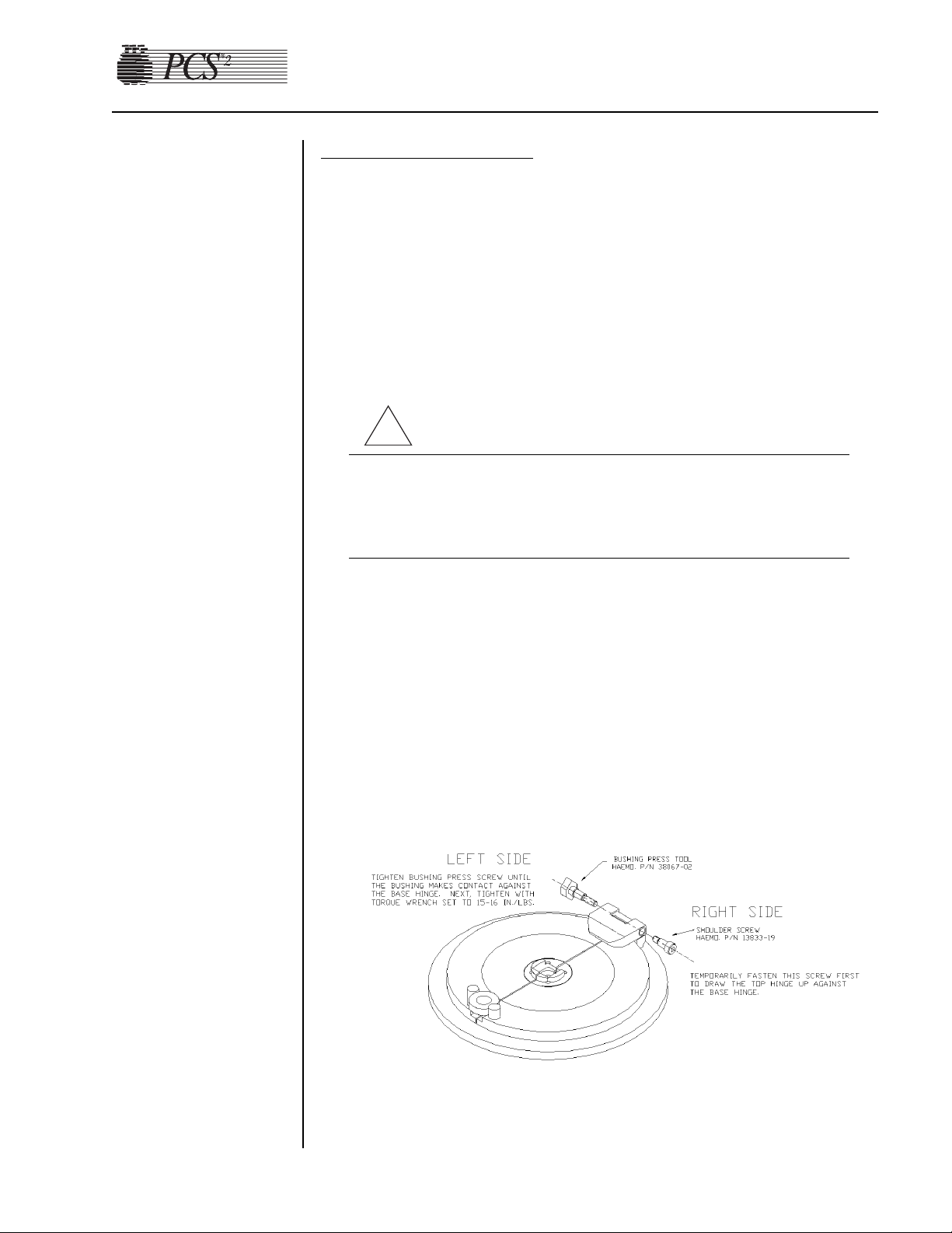
3. Using the L-Hex wrench, temporarily fasten the centrifuge cover
hinge on the right side with hex head shoulder screw, P/N 13833-19.
Tighten the screw until the top hinge is drawn up against the base
hinge. (See illustration below.)
!
Page 25
2-14 PCS2 Service Manual
4. Using the 1/2" box wrench, fasten the left side of the cover hinge
using the Bushing Press Tool, P/N 38067-02, and tighten until the
bushing makes contact against the base hinge. (This tool will
physically push the bushing into the cover hinge.) Next, tighten the
Bushing Press Tool with a torque wrench set to 15/16 in./lb., until the
click of the torque wrench is heard. This will ensure a firm press of
the bushing against the base hinge. (See illustration below.)
Warning!
Failure to use a torque wrench set to the correct torque could cause
damage to the bushings and render the centrifuge cover inoperable.
5. Check to make sure there is no side to side movement between the
centrifuge cover hinge and the base hinge.
6. Remove the Bushing Press Tool from the left side of the centrifuge
cover. Apply a couple of drops of purple Loctite to one of the
previously removed headless shoulder screws and install in the cover.
7. Remove the shoulder screw from the right side of the centrifuge cover.
Apply a couple of drops of purple Loctite to the previously removed
headless shoulder screws and install in the cover.
Centrifug
e Cover Reassembly Notes
1. The hex shoulder screws are designed to be completely tightened and
a nylon washer is fitted to provide a moderate amount of rotational
resistance for each cover half. In some cases, completely tightening
the shoulder screw may result in an immobile cover half due to an
oversized nylon washer. In either case, it is extremely important that
the shoulder screw is secured to the cover hinge with Loctite.
Otherwise the shoulder screw may loosen and cause the cover half to
vibrate.
2. Also, since the cover halves are hinged, they must be aligned so they
simultaneously touch the cover latch when closed.
3. First mount one cover half completely.
4. Lower the cover half and slide it closed against the cover latch.
5. Position the second cover half, with the nylon washer installed, along
the cover latch and the cover hinge.
6. Carefully slide the cover halves open (they are now geared), while
maintaining the proper cover hinge position, then raise the cover
halves.
7. Loctite and install the shoulder screw into the second cover half.
!
Page 26

Chapter 2, Machine Part Replacement Reference 2-15
8. Test the position of the two cover halves when closed against the
cover latch.
Cover Switch Assembl
y
1. Remove the centrifuge from the cabinet.
2. Remove the (2) #4 socket head screws or Phillips head screws
securing the cover switch assembly to the centrifuge well.
3. Pull the cover switch assembly away from the centrifuge well.
Co
ver Switch Reassembly Notes
1. The cover switch assembly mounting position is a calibration step.
2. Set switch engagement of cover switch assembly to the bottom of the
shaft so that there is 3/8 to 5/8 clockwise turn of the centrifuge knob
after both switches have been disengaged.
Cover Latch
Note: The cover latch is not designed for disassembly. These instructions
are provided in case the cover latch requires replacement.
1. Remove the knob disk. This can be accomplished by placing a thin
flat screwdriver in the gap between the knob disk and the knob and
tapping on the back of the handle of the screwdriver until the cap
detaches from the knob.
Note: The knob disk is loctited to the knob. It may be difficult to detach
and require more force to separate it from the knob. Do not worry
about damaging these components as they are going to be replaced.
2. Remove the centrifuge from the cabinet.
3. Remove the cover switch assembly from the centrifuge.
4. Remove the knob by unscrewing the retaining screw and unscrewing
the knob from the centrifuge lock shaft.
5. Twist the centrifuge shaft spacer counterclockwise using vice grips or
locking pliers. As the centrifuge shaft spacer is removed, the
centrifuge lock shaft will drop out from the bottom of the centrifuge
cap assembly. Save the spring for reuse with replacement parts.
6. Place the compression spring on the replacement lock shaft and insert
it into the centrifuge cap assembly.
7. Prime and loctite the lock shaft threads at the base only, and then
screw the centrifuge shaft spacer (threads up) on the lock shaft until
the spacer bottoms out. Be sure that no loctite is touching the
centrifuge cap assembly where the shaft and the spacer come into
contact with the centrifuge cap assembly.
Page 27

2-16 PCS2 Service Manual
8. Thread the large knurled centrifuge knob (flat side up) onto the lock
shaft.
9. Install the o-ring into the channel of the centrifuge knob cap. Apply a
light coating of vacuum grease or o-ring lubricant.
10. Apply a small amount of purple loctite onto the top of the lock shaft
and thread the knob cap onto the shaft. Tighten the cap down using a
small set of needle-nose or snap-ring pliers.
11. Close centrifuge cover halves to check the general operation of the
assembly.
12. Apply a small amount of green loctite to the underside edge of the
knob disk and set it onto the knob cap. Wipe off any excess loctite.
13. Install the cover switch assembly and calibrate the switch position.
14. Install the centrifuge into the cabinet.
Fluid Sensor Assembly
1. Remove the (1) center Phillips head screw from the fluid sensor
assembly pcb.
2. Gently twist the fluid sensor assembly out of the centrifuge well.
3. When reinstalling, place a bead of rtv around sensor housing to seal.
Note: Ensure that the rtv does not cover the face of the detector.
Bo
wl Optics Assembly
Note: Do not perform this procedure unless you have the necessary test
fixtures to realign after reassembly. (This includes the optical alignment
fixture and photographic gray card. See Chapter 4, Calibration.)
1. Remove the (1) Phillips head screw securing the ground to the optics
assembly.
2. Using a 1/4" wrench (or equivalent), remove the (4) #4-40 hex nuts
securing the optics assembly to the centrifuge well and pull off the (2)
wedge-shaped spacers.
3. Gently push the top of the optics assembly into the centrifuge well,
and guide the optics pipe through the cavity.
4. To remove the optics cable, firmly hold the optics assembly and, using
a locking plier, grip the brass threaded coupler and unscrew the optics
cable from the optics assembly.
5. Very carefully, remove any debris in the optics assembly (cable)
threaded hole. Any dried primer/Loctite could interfere with the
transmission of light.
Page 28

Chapter 2, Machine Part Replacement Reference 2-17
Bowl Optics Reassemb
ly Notes
Refer to Chapter 4, Calibration, to properly adjust and calibrate the optics
after reassembly.
1. Remove the front and rear panels. (See page 2-2.)
2. Disconnect P504 from the backplane card (located in the lower right
hand corner).
3. Disconnect the display ground wire from the ground bus on the
cabinet side (located on the left side when looking from the front of
the cabinet).
4. Remove the (2) lower Phillips head screws securing the membrane
panel ribbon cable to the upper deck (located above the card cage at
the rear of the cabinet).
5. Using a #10 hex bit, remove the (2) shoulder screws securing the top
cover assembly to the top deck while supporting the top cover assembly.
Membrane P
anel Assembly
1. Remove the (2) Phillips head screws securing the fiberglass decorative
panel to the top cover assembly (inside hinge area).
2. Remove the (3) Phillips head screws securing the membrane panel to
the top cover assembly.
3. Simultaneously pull the base of the membrane panel down and away
from the top cover assembly to disengage the top panel catches from
the catch plate.
4. Carefully pull the top of the membrane panel down to expose the
inner wiring of the membrane panel.
5. Remove the (1) Phillips head screw on the top cover, securing the
ground wire from the membrane panel to the top cover ground
surface.
6. Disconnect the ribbon cable from the card cage assembly by
following steps 1-4 of the disassembly instructions for the top cover
assembly or go to step 7.
7. Using a 1/4" wrench (or equivalent), remove the (2) #4-40 nuts
securing the ground from the ribbon cable to the top cover mounting
plate.
8. Using a 1/4" wrench (or equivalent), remove the (2) #4-40 nuts
securing the ribbon cable strain relief.
9. Disconnect P804 from the display distribution board.
Top Cover
Assembly
Page 29

2-18 PCS2 Service Manual
Control Panel Distribution Cable
Note: The old-style cable is a multicolored ribbon cable and the new-style
cable is a solid blue ribbon cable.
Remo
v
al of the old cable.
1. Remove front and rear panel assembly.
2. Remove decorative and membrane panel assembly.
3. Remove the old cable assembly and the two brackets, discard all three
components and retain the screws for use later.
4. Remove the retainer pad in the cover that the cable lay across and
discard.
5. Remove the two Allen shoulder screws that secure the top cover to the
deck.
6. Remove the two Phillips head screws holding the third cable bracket
attached to the top deck (above card cage), discard bracket and retain
screws for use later.
Installation of ne
w cable and parts.
1. Mount the body clamp (P/N 47132-02) to the deck using the two #632 x 3/8" long Phillips flat head screws (removed above) with a drop
of purple Loctite. (Orient so that the long step is toward the centrifuge
cut-out.)
2. Reinstall the top cover onto the top deck assembly, using the two
Allen head shoulder screws removed above.
Note: Reinstall all ground wires that may have been removed when
removing the old cable, except the ground wire with the old cable.
This ground wire and old cable are to be discarded.
3. On the membrane panel assembly, connect one end of the new
distribution cable assembly (35231-00) to the display dist. PCB
connector (P804). Secure the copper tape under the strain relief block
and secure with the two #6-32 small pattern keps nuts (removed
previously).
Note IMPORTANT: The strain relief block must be in the center of the
copper tape.
4. Install the new retainer pad (P/N 13549-02) onto the back of the
decorative panel, centered on the radius and aligned with the edge.
5. Cut the EMI shielding tape (P/N 47015-00) into two 2" ± ¼" pieces,
remove the protective paper from one piece and attach it lengthwise to
the top cover, gray portion at the bottom, align with the center of the
hinge nut plate and then affix onto the hinge nut plate about halfway
up the hinge.
Note: Make sure that the hole for the decorative panel is not covered.
Page 30

Chapter 2, Machine Part Replacement Reference 2-19
Remove the protective paper from the other piece of tape and attach it
in the same manner inline with the other hinge nut plate.
6. Reinstall the membrane panel onto the top cover.
7. Reinstall the decorative panel onto the top cover.
8. Cut double-sided tape (P/N 18142-00) to a length of 1½" ± ¼".
Adhere the tape to the underside of one of the EMI ferrite attenuators
(P/N 39475-00).
9. Sandwich the ribbon cable from the top cover assembly between the
attenuator with the tape and the attenuator (P/N 39475-00) without the
tape at approximately 4" ± ¼" from the end of the cable jacket.
Note: The attenuator with the tape must be toward the card cage.
10. Install the two spring clips (P/N 47241-00) over each end as shown,
reference balloon #50.
Note: The flat end of the spring clip must be toward the card cage.
11. Remove the protective paper from the tape on the attenuator and
adhere the attenuator assembly with the ribbon cable to the top of the
card cage.
Note: Do not cover slots in top of card cage.
12. Apply purple Loctite to the threads of the two #6-32 x 3/8" Phillips
flat head screws (removed previously). Make sure the ribbon cable
from the cover assembly is centered in the deck body clamp and
secure the copper tape of the cable assembly under the strap clamp
(P/N 47133-02) and secure in place with the Loctited screws.
Note IMPORTANT: The copper tape must be centered in the strap
clamp.
13. Reinstall cable connector into the backplane card.
14. Complete a Diagnostic and Functional Test according to the
procedure outlined in Chapter 3.
Page 31

2-20 PCS2 Service Manual
Display Distribution Board
1. Remove the membrane panel assembly from the top cover assembly.
(See page 2-17.)
2. Disconnect P801 and P804 from the display distribution board.
3. Place the membrane panel on a flat level surface and remove the (4)
Phillips head screws securing the display distribution board to the top
cover mounting plate.
4. Carefully pry the display distribution board up to disconnect the
display distribution board from the membrane panel at P803.
Vacuum Display
1. Remove the membrane panel assembly from the top cover assembly.
(See page 2-17.)
2. Disconnect CN1 and CN2 from the vacuum display.
3. Place the membrane panel on a flat level surface and remove the (4)
Phillips head screws securing the vacuum display to the top cover
mounting plate.
4. Carefully lift the vacuum display up and away from the top cover
mounting plate.
Membrane Panel
1. Remove the membrane panel assembly from the top cover assembly,
and remove the display distribution board from the top cover
mounting plate.
2. Using a 1/4" wrench (or equivalent), remove the (6) perimeter #6-32
small pattern nuts securing the top cover mounting plate to the top
cover panel fascia.
3. Using a 1/4" wrench (or equivalent), remove the (1) #6-32 small
pattern nut securing the membrane panel ground strap to the
membrane panel mounting lug and pull the ground strap off the lug.
4. Using a 5/16" wrench (or equivalent), remove the (7) perimeter and
(1) central #6-32 small pattern nuts, and the (1) #6-32 nut securing the
membrane panel to the top cover mounting plate.
5. Pull the top cover mounting plate away from the top cover panel
fascia.
6. Remove the nylon spacer and washer from the central membrane
panel mounting lug. Save the nylon spacer and washer for reuse with
the replacement membrane panel.
7. Using considerable force, peel the membrane panel edges away from
the top cover panel fascia and push the membrane panel through the
top cover panel fascia. The membrane panel cannot be reused.
Page 32

Chapter 2, Machine Part Replacement Reference 2-21
Power Supply
Assembly
1. Remove the rear panel. (See page 2-2.)
2. Using a 1/4" wrench (or equivalent), remove (2) #4-40 nuts on either
side of the power input module.
3. Disconnect the left top (blue) and bottom (brown) AC power lines
from the power input module and disconnect the ground lug from the
ground bus on the cabinet.
Fuse
1. Pry above the power switch on the power entry module to open the
fuse cover.
2. Pry out each fuse holder.
3. Replace with same size and rating fuse (5a 250V).
Fuse Holder Reassembly Notes
When replacing fuse holders, be sure arrows on fuse holder and power
input module face the same direction.
Replace T
odd Po
wer Supply with Todd Power Supply
Note: Use the following directions if replacing a Todd power supply (P/N
18878-00) with another Todd power supply.
1. Remove the front and rear panels. (See page 2-2.)
2. Disconnect P1, P2, and P3 from the centrifuge controller card.
3. Disconnect P405 from the centrifuge distribution card and thread the
cable through the cabinet to the photoelectric assembly.
4. Disconnect P507 from the backplane card.
5. Remove the (4) Phillips head screws securing the power supply cage
access panel, and remove the panel (located at the rear of the cabinet).
6. Using a 11/32" wrench, remove the (2) #8-32 hex nuts securing the
line conditioner to the cabinet, and pull the line conditioner away
from the cabinet.
7. Unplug the L (brown, located on the left) and N (blue, located on the
right) AC power lines from the power supply.
8. Using a 5/16" wrench, disconnect the (1) #6-32 nut and ground from
the power supply fan.
9. Remove the (2) optic cables from the photoelectric assembly by
unscrewing the (2) plastic thumb screw fasteners.
10. Remove the (2) Phillips head screws securing the power supply cage
to the cabinet.
11. Pull the power supply cage out the rear cabinet cavity by lifting the
rear edge and pulling the front edge away from the plastic edge clips
on the cabinet base.
Power Entry
Module
Page 33

2-22 PCS2 Service Manual
12. Remove the (6) Phillips head screws securing the power supply top
cage to the power supply frame.
13. Disconnect P1 on the power supply. This is not an easy job. Take great
care not to dislodge any cables from the P1 connector.
14. Remove the (4) Phillips head screws securing the power supply to the
power supply frame.
15. Lift the power supply away from the power supply frame. Do not
remove the fan. It cannot be replaced separately from the power
supply.
16. Recalibrate the Todd Power Supply, referring to the procedure in
Chapter 4, Calibration.
T
odd Po
wer Supply Reassembly Notes
1. Partially insert the power supply cage into the cabinet from the rear
cavity, and then align the frame with the plastic edge clips from the
front cavity.
2. Be sure to insert the AC wires from the line filter into the rubber
grommet, and insert the grommet into the power supply cage.
Replace Todd Power Supply with Condor Power Supply
Note: Use the following directions if replacing a Todd power supply
assembly (P/N 37121-00) with a Condor power supply assembly
(48895-00).
1. Remove front and rear panels. (See page 2-2.)
2. Remove the Todd power supply. (See page 2-21, steps 2 through 11.)
Note: Removal of the power supply board from the power supply cage is
not necessary. The Condor power supply assembly replaces the
power supply board and the cage. However, the AC lines (L and N
wires) need to be removed from the line conditioner and the power
supply ground wire needs to be removed from the GND terminal
block of the PCS2 cabinet.
3. Remove the centrifuge controller card from the power supply cage.
(See page 2-24.)
4. Remove the photoelectric assembly from the power supply cage. (See
page 2-24.)
5. Attach the centrifuge controller card on the (4) standoffs located on
the right hand bracket of the Condor power supply assembly using the
same (4) Phillips head screws.
Note: The heatsink, the long, rectangular black component, on the
centrifuge controller card is located toward the bottom of the frame
Page 34

Chapter 2, Machine Part Replacement Reference 2-23
when the card is mounted. If the heatsink is located toward the top
of the frame, there will not be enough slack in the harnesses to reconnect P1, P2, and P3.
6. Mount the photoelectric assembly to the power supply plate of the
Condor power supply assembly using the same (2) Phillips head
screws.
Note: Mount the photoelectric assembly with the harness, P405, facing
the same direction as the Condor power supply harness, P507.
7. Remove the protective label on the back of the cord clip and affix the
cord clip to the side of the cabinet above the line conditioner.
8. Partially insert the power supply assembly into the cabinet from the
rear cavity, and then align the frame with the plastic edge from the
front cavity. Align the rear brackets of the power supply with the two
threaded holes of the cabinet’s bottom panel and secure the power
supply assembly to the cabinet by using the (2) Phillips head screws.
9. Connect the 3 wire harness assembly (AC lines) on the power supply
as follows: Quickslide (blue wire) to N terminal of the line
conditioner, Quickslide (brown wire) to L terminal of the line
conditioner and attach the green wire to the GND terminal block of
the PCS2 cabinet using (1) Phillips head screw and star washer.
10. Reattach P1, P2, and P3 to the centrifuge controller card.
11. Reattach the fiber-optic cables to the photoelectric assembly by
unwrapping the cables around the centrifuge and running them
through the cord clip to the photoelectric assembly.
12 Reattach P405 to the centrifuge distribution card.
13. Reattach P507 to the backplane board.
14. Recalibrate the Condor power supply referring to the procedure in
Chapter 4, Calibration.
Replace Condor Power Supply with Condor Power Supply
Note: Use the following directions if removing a Condor power supply
(P/N 48102-00).
1. Remove front and rear panels. (See page 2-2.)
2. Disconnect P1, P2, and P3 from the centrifuge controller card.
3. Disconnect P405 from the centrifuge distribution card and thread the
cable through the cabinet to the photoelectric assembly.
4. Disconnect P507 from the backplane card.
5. Unplug the L (brown) and N (blue) AC power lines and the Ground
wire from the back of the power supply.
6. Remove the two (2) optic cables from the photoelectric assembly by
unscrewing the two (2) plastic thumb screw fasteners.
Page 35

2-24 PCS2 Service Manual
7. Remove the (2) Phillips head screws securing the power supply
assembly to the cabinet.
8. Pull the power supply assembly out the rear cabinet cavity by lifting
the rear edge and pulling the front edge away from the plastic edge
clips on the cabinet base.
9. Remove the two (2) Phillips head screws securing the left hand
bracket to the power supply.
10. Remove the four (4) Phillips head screws securing the right hand
bracket to the power supply.
11. Slide the power supply away from the power supply mounting frame.
12. Recalibrate the Condor power supply referring to the procedure in
Chapter 4, Calibration.
Centrifuge Controller Card
1. Remove front and rear panels. (See page 2-2.)
2. Disconnect P1, P2, and P3 from the centrifuge controller card.
3. Remove the (4) Phillips head screws securing the centrifuge controller
card to the power supply assembly cage.
4. Recalibrate the centrifuge referring to the procedure in Chapter 4,
Calibration.
1. Remove the rear panel. (See page 2-2.)
2. Remove the (2) Phillips head screws securing the AC or saline pole
holder assembly to the cabinet.
1. Tilt the cabinet and remove the (4) Phillips head screws securing the
spill bag plate to the base of the cabinet.
2. Carefully cut the tubing from the drain tube.
3. Replace with new drain tube assembly.
1. Remove the rear panel. (See page 2-2.)
2. Disconnect P405 from the centrifuge distribution card.
3. Remove the (2) fiber-optic cable ends from the photoelectric assembly
by unscrewing the (2) plastic thumb screw fasteners.
4. Remove the (2) Phillips head screws securing the photoelectric
assembly to the power supply assembly cage.
Note: When reinstalling fiber-optic cable ends into the photoelectric
assembly, tighten plastic fasteners securely. Refer to Chapter 4,
Calibration, to adjust the bowl optics signal.
Photoelectric
Assembly
AC and Saline
Pole Holder
Assembly
Drain Tube
Assembly
Page 36

Chapter 2, Machine Part Replacement Reference 2-25
Line
Conditioner
1. Remove the rear panel. (See page 2-2.)
2. Unplug the brown and blue AC power lines from the line conditioner
top & bottom.
3. Using a 11/32" wrench, remove the (2) #8-32 hex nuts securing the
line conditioner to the cabinet, pull the line conditioner away from the
cabinet.
Page 37

2-26 PCS2 Service Manual
TTaabbllee 22-11,, PPCCSS22 CCoommppoonneenntt CCaalliibbrraattiioonn aanndd DDiiaaggnnoossttiicc MMaattrriixx
CALIBRATE
Replaced Part A/D: Cuff A/D: Weigher A/D: DPM Centrifuge Safety System Bowl Optics Line Sensor Power Supply
Processor PCB
Safety PCB
Driver PCB
Centrifuge Controller PCB
Front Panel Distribution PCB
Load Cell
DPM
Compressor
Centrifuge Assy
Photoelectric Assy X
Line Sensor
Bowl Optics Assy
Power Supply
DIAGNOSTIC CHECK
Replaced Part Pumps Valves Weigher Pressure Centrifuge Display Keyboard Transducers Air Detectors
Pump Motor (Blood or AC)
Pinch Valves
(Blood, Plasma, Saline)
Top Deck Distribution PCB
Membrane Panel Assy
Control Panel Distribution Cable
Centrifuge Distribution PCB
Air Detector
(BLAD, ACAD, DLAD 1 or 2)
Fluid Sensor Assy
Cover Switch Assy
Note: Shaded boxes indicate that a Calibration or Diagnostic Check of the appropriate part needs to be performed.
Page 38

Visual Inspection
Visually inspect the following items to ensure that they appear to be in
good working order and do not have obvious scratches, dents, or broken
or missing hardware. Note physical damage. Note missing or loose
hardware. Tighten and/or replace hardware as necessary. Scratched and/or
dented hardware need not be replaced unless the damage interferes with
the operation of the machine.
• Outside of cabinet
• Screws for front and back panels (3 in front and 3 in back)
• Cooling fans (mounted on rear panel)
• Pressure cuff (check for fatigue – cracking of the tubing or the cuff
material and/or leaks when pressurized, indicates the need for
replacement)
• Membrane panel
• Pump rotors
• Pump rotor screws (1 in the center of each rotor)
• Tubing guides
• Weigher arm
• Screw for weigher arm (at the pivot point of the weigher arm)
• Centrifuge cover
• Screws in the hinge of the centrifuge cover
• Thumb screw cap (if missing check that the screw in the center of
the thumb screw is still in place and tight)
• Line sensor
• Line sensor access plug
• Air detectors
• System pressure monitor (not present on List Number 06002-110NA machines)
• Donor pressure monitor
Chapter 3
Basic Care and Preventive Maintenance
Initial
Inspection
Page 39

Ensure Initial Operational Integrity
Power on the PCS2 and ensure that it passes the initialization and safety
system test before going on to test the machine. (This will ensure that the
machine was operational before it was tested and alleviate any doubt
whether the service technician’s adjustments caused a problem should the
machine fail to operate properly after the PM is complete.)
Record the Program Revision Le
vel
The program revision level is displayed on the screen just after the
centrifuge interlock switch is tested during the self test of the machine.
Watch for this revision level after you complete the locking and unlocking
of the centrifuge cover as instructed on the display by the machine.
Refer to Chapter 8 for cleaning procedures.
Electrical Connections Inspection
1. Remove the front and the back panels to gain access to the internal
components.
2. Inspect for loose or broken electrical connections on all major
assemblies. Tighten or repair as required.
Pneumatic Connections Inspection
Inspect the pressure connections at the cuff compressor and in-line filters.
Tighten and repair as required.
Hardware Inspection
1. Inspect for loose or missing mounting hardware. Tighten and repair as
required.
2. Inspect the centrifuge drain tubes for proper placement. Ensure that
there is unobstructed passage for fluids from the centrifuge.
3. Inspect the centrifuge mounting location to ensure that the centrifuge
does not contact the deck. There should be a clearance of at least 1/8
of an inch between the centrifuge and the cavity in the deck all the
way around the centrifuge, and a visible gap between the base of the
centrifuge rim and the deck surface.
3-2 PCS2 Service Manual
System
Cleaning
Equipment
Integrity
Inspection
Page 40

Chapter 3, Basic Care and Preventive Maintenance 3-3
Filter Inspection
Inspect for the following filters. Refer to the repair parts list in Chapter 7
for correct part numbers to replace if worn.
• The three air filters on the bottom of the machine.
• The two cuff compressor filters on the front panel.
The components in the PCS2 generate enough heat that some circuits may
drift if the cooling system is not intact. For this reason, the rear panel
should always be propped into place whenever direct access through the
rear opening is not necessary. The cooling system is even more efficient
when both panels are in place, but it may be impractical to repeatedly
remove and replace the front panel. If a voltage measurement is needed,
be sure the internal temperature has stabilized before testing.
P
ower Supply V
oltages T
est
1. Power on the PCS2 in the Utilities mode of operation by pressing and
holding the PLASMA key while switching the power on. Hold the
PLASMA key until the Utilities menu appears on the display.
2. Measure the power supply voltages at P507 on the backplane card.
Use pin seven for DC common/ground. Note: Pins 1 thru 7 are all
common/ground.
PIN # Voltage Tolerance
8 +5.1 +0.1 / -0
9 +5.1 +0.1 / -0
10 +15.0 ±0.5
11 –15.0 ±0.5
12 +28.0 +1.0 / – 0.2
13 +28.0 +1.0 / – 0.2
14 +48.0 +47 to +57
Figure 3-1, Backplane Card
Consumables
Replacement
Calibration
Testing
Page 41

Note: The labeling of P507 test points located on the Backplane board are
for reference in this illustration and do not appear on the Backplane
board.
Valves T
est
1. Power on the PCS2 into the Utilities mode of operation by pressing
and holding the PLASMA key during power up until the Utilities
menu appears.
2. Select Diagnostics on the Utilities menu by pressing the MODIFY
PROGRAM key until the arrow points to Diagnostics, then press the
DRAW key.
3. Select the Valves test by using the MODIFY PROGRAM key to move
the arrow to “Valves” test and the DRAW key to execute.
4. Open all three valves by pressing the SALINE, PLASMA, and CUFF
keys.
5. Insert tubing from a PCS2 harness set, LN 620, into each valve and
press the DRAW key to start cycling the valves.
6. Allow valves to cycle for at least one minute, then press the STOP
key. Verify that at the end of one minute, no errors have accumulated
in the error log. If errors exist, determine which valve is causing the
error by running the cycle test again. Isolate problem to power
(Eng./De-eng.) position switch (Open/Closed), or valve current (Highcurrent). Refer to Chapter 6, Troubleshooting.
7. Exit the Valves test by pressing the MODIFY PROGRAM key.
Valve Occlusion Test
1. Select Diagnostics on the Utilities menu by pressing the MODIFY
PROGRAM key until the arrow points to Diagnostics, then press the
DRAW key.
2. Select the Valves test by using the MODIFY PROGRAM key to move
the arrow to the “Valves” test and press the DRAW key to execute.
3. Open all three valves by pressing the SALINE, PLASMA, and CUFF
keys.
4. Install a length of the harness tubing through the open Saline pinch
valve (white) and attach one end to a sphygmomanometer.
Note: When performing the pinch valve occlusion test, it is important to
ensure that the test harness setup does not contain any leaks that
might indicate false occlusion results. This can be verified by
attaching the sphygmomanometer to the harness tubing and
clamping the opposite end of the tubing. Pressurize the
sphygmomanometer to 200 mmHg and verify that there is no
leakage evidenced by a decrease in pressure.
3-4 PCS2 Service Manual
Page 42

5. Press the SALINE key and the valve will close.
6. Pressurize the sphygmomanometer to 200 mmHg and verify that there
is no leakage evidenced by a decrease in pressure. Press the SALINE
key and remove the tubing.
7. Install a length of the harness tubing through the open Plasma pinch
valve (yellow) and attach one end to a sphygmomanometer.
8. Press the PLASMA key and the valve will close.
9. Pressurize the sphygmomanometer to 200 mmHg and verify that there
is no leakage evidenced by a decrease in pressure. Press the PLASMA
key and remove the tubing.
10.Install a length of the harness tubing through the open Donor pinch
valve (red) and attach one end to a sphygmomanometer.
11.Press the CUFF key and the valve will close.
12.Pressurize the sphygmomanometer to 200 mmHg and verify that there
is no leakage evidenced by a decrease in pressure. Press the CUFF key
and remove the tubing.
14.Exit the Valves test by pressing the MODIFY PROGRAM key.
Weigher Test
1. Be sure the weigher arm is fully extended with nothing hanging on it.
Select the Weigher test on the Diagnostics menu by pressing the
MODIFY PROGRAM key, then press the DRAW key.
2. Verify the displayed weight is ZERO ±1.
3. Hang the following calibrated weights on the weigher and verify that
the displayed weight is within the defined specification.
• 1000 ± 5 grams
4. Remove the weights and verify that the displayed weight returns to
ZERO ±1.
5. If calibration is required, refer to the calibration section in the next
chapter.
6. Exit the Weigher test by pressing the MODIFY PROGRAM key.
DPM Sensor Test
1. Be sure no filters are connected to the DPM and SPM. Select the
Pressure test in Diagnostics using the MODIFY PROGRAM and
DRAW keys.
Note: List Number 06002-110-NA machines do not have the SPM.
2. Verify that the DPM offset is within the range of 1984 – 2112. If out
of range, DPM may need to be replaced.
3. Grasp the DPM white plunger and twist counterclockwise while
sliding in the plunger. Verify that both interlock switch status
indicators change to IN. Release the plunger and verify that both
indicators return to OUT.
Chapter 3, Basic Care and Preventive Maintenance 3-5
Page 43

3-6 PCS2 Service Manual
4. Grasp the DPM white plunger and twist clockwise while sliding in the
plunger. Verify that both interlock switch status indicators change to
IN. Release the plunger and verify that both indicators return to OUT.
5. Install a DPM filter with about 4" of tubing onto the DPM. Connect a
calibrated sphygmomanometer or equivalent device to the filter
tubing. Pressurize the DPM to 300 mmHg and verify that the
displayed pressure reading is within the range of 292 - 308 mmHg.
6. If calibration is required, refer to Chapter 4, Calibration.
Cuff Test
1. Install a cuff adaptor tubing with a sphygmomanometer (or
equivalent) attached into the rear panel cuff connector.
2. Turn the cuff compressor on by pressing the CUFF key.
3. Verify the cuff inflates to 50 ± 5 mmHg.
4. Use the YES key to increase the cuff pressure to 100.
5. Verify the cuff inflates to 100 ± 10 mmHg.
6. If calibration is required, refer to Chapter 4, Calibration.
7. Exit the Pressure test by pressing the MODIFY PROGRAM key.
Displa
y Test
1. Select the Display test in Diagnostics using the MODIFY PROGRAM
and DRAW keys.
2. Verify that all pixels are lit on display, then press DRAW.
3. Verify that character set is displayed and no characters are deformed
or missing.
4. Exit the Display test by pressing the MODIFY PROGRAM key.
Keyboard Test
1. Select the Keyboard test in Diagnostics using the MODIFY
PROGRAM and DRAW keys.
2. Press each key (save MODIFY PROGRAM key for last) and verify
that LED extinguishes (if equipped) and Key Pressed value indicates
the correct key name.
3. Pressing the MODIFY PROGRAM key exits the Keyboard test.
Page 44

Fluid Sensor Test
1. Select the Centrifuge test in Diagnostics using the MODIFY
PROGRAM and DRAW keys.
2. Open the centrifuge cover and place a moist paper towel or cotton
swab on the fluid sensor located in the centrifuge well. Verify that the
SPILL value changes to TRUE.
3. Remove moisture and wipe dry. Verify that the SPILL value changes
to FALSE.
Centrifuge Cover and Lock Functional Test
1. Close centrifuge cover and slowly rotate the cover lock until the
COVER value changes from UNLOCKED to LOCKED. Verify that
the cover knob can be turned an additional 3/8" to 5/8" after the cover
lock switches activate.
2. If adjustment is required, refer to Chapter 2, Machine Part
Replacement Reference.
Centrifug
e Speed and Bowl Vibration Test
1. Install a bowl partially filled with water (approximately 2/3 full) into
the centrifuge. Close and lock the centrifuge cover.
2. Start the centrifuge by pressing the DRAW key. Verify that the
centrifuge speed stabilizes to 7000 ± 100 rpm.
3. If calibration is required, refer to Chapter 4, Calibration.
4. As the centrifuge is spinning, observe the air/water interface in the
bowl and listen for any signs of centrifuge contact with the chassis.
Verify that the air/water interface never becomes discontinuous,
indicating excessive vibration.
5. If excessive vibration or noise is observed, refer to the Chapter 2,
Machine Part Replacement Reference to realign the centrifuge.
6. Press the STOP key to stop the centrifuge and remove the bowl from
the centrifuge.
7. Exit the centrifuge test by pressing the MODIFY PROGRAM key.
Donor Lights Test
1. Select the Donor Lights test in Diagnostics using the MODIFY
PROGRAM and DRAW keys.
2. Verify that when instructed all LEDs light and extinguish.
3. Exit the Donor Lights test by pressing the MODIFY PROGRAM key.
Chapter 3, Basic Care and Preventive Maintenance 3-7
Centrifuge
Testing
Page 45

3-8 PCS2 Service Manual
Line Sensor Test
1. The PCS2 must be powered on for a minimum of 15 consecutive
minutes before proceeding with this test. When 15 minutes has
elapsed, proceed with the Line Sensor testing.
2. Select the Transducers test in Diagnostics using the MODIFY
PROGRAM and DRAW keys.
3. Verify that no tubing is installed in the line sensor, and that the digital
reading for the line sensor signal is between 2866 to 3276.
4. Slide a black non-reflective surface into the line sensor tubing slot.
(Dull paper with dull black marker on both sides works well for this).
Verify that the line sensor signal drops between 0 to 103.
5. If calibration is required, refer to Chapter 4, Calibration.
Bowl Optics Signal Test
1. The PCS2 must be powered on for a minimum of 15 consecutive
minutes to stabilize the optic circuit before proceeding with this test.
When 15 minutes has elapsed, proceed with the optics testing.
2. Inspect the optic window for contamination and clean before
measuring the optics signal.
3. Remove the gray card from the envelope in the Gray Card
Replacement Kit.
4. Make a note of the Correction Factor written on the back of the gray
card.
5. Insert the gray card into the optic alignment fixture so that the arrow
on the back points up into the optic fixture.
Note: • If the optic alignment fixture has a gray card installed, remove
the gray card and discard. The gray card used in the optic
alignment fixture must be uncontaminated by light or material.
• Ensure the white backing of the gray card is not “yellow.”
• Ensure the gray measuring surface is not physically damaged.
• Ensure the gray card is less than one year older than the date
printed on the back of the card.
6. a) If testing the optics signal to a digital value, select the Transducer
test in Diagnostics.
b) If testing the optics signal to an analog voltage, connect a digital
voltage meter, (greater than 3½ digit resolution), to J105 (top plug)
pin 9 (signal) and pin 5 (ground) on the Processor Card.
7. Ensure the centrifuge chuck is empty. Verify the average analog or
digital reading for the bowl optics offset signal is between 1 to 82
digital units or -0.10 to +0.10 VDC.
8. Install the optic fixture ETD 5060 in the centrifuge and rotate it until
the optic beam is centered on the gray card.
Page 46

9. Close the centrifuge cover to allow the cover’s bowl collars to lock
around the optic fixture’s square alignment tabs.
10.Make a note of the actual digital or analog voltage optic gray card
reading.
11.Use the Correction Factor printed on the back of the gray card and the
formula below to calculate the optic gain being measured. Ensure the
calculated optic reading with Correction Factor is between 2295 to
3278 digital units or +2.8 to 4.0 VDC.
Use the following formula to determine the optic gain with Correction
Factor:
Optic Digital Gain with Correction Factor = Actual Digital Gray Card Reading ÷
Correction Factor
or
Optic Voltage Gain with Correction Factor = Actual Optic Gray Card Reading
(VDC) ÷ Correction Factor
Example:
The actual gray card reading is 2397 digital units or 2.926 VDC
The Correction Factor on the back of the gray card = 0.829
Optic Digital Gain with Correction Factor = 2397 ÷ 0.829 = 2891 digital units
or
Optic Voltage Gain with Correction Factor = 2.926 VDC ÷ 0.829 = 3.53 VDC
12.If calibration is required, refer to the Bowl Optics Signal Calibration in
Chapter 4.
Note: The bowl optics signal test (operational) range described above
differs from the bowl optics signal calibration range in the
Calibration Chapter. The optics calibration range is utilized to
adjust the optics gain if it is found to be outside the acceptable optic
calibration test range.
When documenting the optic signal value, ensure the voltage
recorded is the calculated optic signal value, not the actual gray
card reading. In the above example in step 11, the optic signal value
recorded would be 2891 digital or +3.53 VDC.
Chapter 3, Basic Care Preventive Maintenance 3-9
Page 47

Warning!
The Correction Factors used in the above calculations are example
values only. Each gray card is individually indexed and the
Correction Factor may vary for each card. The Correction Factor
from the actual card being used must be incorporated into the
optics signal calibration and testing calculations.
Air Detector Test
1. Select the Air Detector test in Diagnostics using the MODIFY
PROGRAM and DRAW keys.
2. Place fluid-filled tubing in air detector under test as requested, verify
the air detector LED lights, and press the DRAW key as requested.
3. Repeat test for each air detector as asked. When the last air detector
has been tested, a screen will appear showing the status of the four air
detector signals. Confirm that each air detector can see fluid and air
by inserting a piece of fluid-filled tubing into each air detector while
monitoring the Polled and Latched signals. With water-filled tubing
inserted, screen will read “Fluid” when empty, screen will read “Air.”
4. If an air detector fails the testing, refer to the Troubleshooting
Chapter.
5. Exit the Air Detector test by pressing the MODIFY PROGRAM key.
6. Exit Diagnostics by pressing the STOP key.
PCS2 Functional T
est
1. Exit Utilities by pressing the STOP key. The PCS2 will reboot and
execute the system start-up sequence. Respond to any questions or
warning as the test progresses. Select a new procedure if prompted.
2. Ensure a cuff is installed in the rear panel connector and all four
exhaust fans are operating and blowing air out of the rear panel.
3. Lock and unlock centrifuge cover as prompted.
4. Verify the PCS2 advances to the Weigher Test screen. With no weight
on the weigher, verify the displayed weight is ZERO ± 1 gram. If it is
outside this range, press the DRAW key to tare the weigher. Hang a
1000g calibrated weight on the weigher. Verify that the displayed
weight is 1000 ± 5 grams.
5. Remove the weight and verify the displayed weight returns to
ZERO ± 1 gram.
6. Press the YES key and verify that the Install Disposable screen is
displayed.
3-10 PCS2 Service Manual
!
Page 48

Chapter 3, Basic Care Preventive Maintenance 3-11
7. At Install Disposable screen perform the following:
• Install partially water-filled bowl in the centrifuge and lock the
centrifuge cover.
• Install a DPM filter in the DPM.
• Floss a segment of clear LN620 harness tubing through the line
sensor.
• Verify that the PCS2 display advances to the Load Pump/Test
Centrifuge screen.
8. Press the PRIME key and verify the following:
• Both pumps turn clockwise for a few seconds, then stop.
• The centrifuge spins for a few seconds, then stops.
9. Press the YES key and verify the Plasma Collection Weight Selection
screen is displayed.
10.Press the MODIFY key and verify the Saline Substitution screen is
displayed.
Note: This screen will only be displayed if the saline option is
programmed. If the saline option is not programmed, verify the
PRIME screen is displayed and proceed to step 12.
11.Press the NO key and verify the PRIME screen is displayed.
12.Install fluid-filled tubing in the AC, DLAD1 and DLAD2 and then
press the PRIME key. Verify machine advances to the Ready screen.
13.Install fluid-filled tubing in the BLAD.
14.Press the DRAW key and verify that both pumps are turning
clockwise, the centrifuge is spinning and the cuff inflates. Also verify
that the donor and plasma valves are open.
15.After a few moments, the “No Pressure Change At DPM” message
will be displayed. Press the DRAW key to continue.
16.Observe the air/water interface in the bowl as the centrifuge is
spinning and listen for any signs of the centrifuge contacting the
cabinet. Verify the air/water interface never becomes discontinuous,
indicating excessive vibration.
17.Press the STOP key. Verify the centrifuge and both pumps stop and all
valves close.
18.Press the RETURN key and verify the End Procedure Option screen is
displayed.
19.Press the YES key and verify the blood pump turns counterclockwise
and the AC pump is not turning. Also verify the donor valve opens
immediately and the plasma valve opens shortly thereafter.
20.Press the STOP key after a few moments and verify the Ready screen
is displayed.
21.Press the STOP key again and verify the Abort Procedure screen is
displayed.
Page 49

22.Press the YES key to abort the procedure and verify the Abort
Procedure Confirmation screen is displayed.
23.Press the DRAW key to abort the procedure and verify the Procedure
Statistics screen is displayed.
24.Remove the test disposable set and verify the machine advances to the
Systems Test screen.
Leakag
e Current
1. Plug the PCS2 into the Leakage Tester (Dale Technologies LT544D
Lite or equivalent).
2. Plug the Leakage Tester into a grounded electrical outlet.
3. Set the meter switch settings as follows:
• Leakage
• Neutral Closed
• Polarity Normal
4. Turn on the PCS2.
5. Note the reading in microamperes on the meter.
6. Depress the GND switch on the meter.
7. Change the Polarity switch from Normal to Reverse.
8. Verify the readings do not exceed 100 microamperes at 120 VAC or
500 microamperes at 240 VAC.
Gr
ound Continuity
1. Change the meter mode to RESISTANCE.
2. Plug the ground wire (coiled wire with clip) into the grounding socket
on the Leakage Meter.
3. Attach the clip to the following exposed metal locations. Verify that
there is continuity.
• Pump - rotor screws
• Rear panel hardware
• Front panel hardware
• Pinch valve plungers
4. Verify the highest reading is less than 1 Ohm.
3-12 PCS2 Service Manual
Safety
Testing
Page 50

Prior to calibration, ensure the PCS2 internal temperature has stabilized
by allowing the machine to power on continuously at least 15 minutes.
The rear panel should always be left in place and removed only prior to
performing calibration.
Todd Power Supply
Note: Use the following calibration procedure if the unit has a Todd
power supply installed (P/N 18878-00).
1. Measure the power supply voltages at P507 on the backplane card.
Use pin seven for DC common/ground.
Note: Pins 1 thru 7 are all common/ground.
PIN # Voltage Tolerance
8 +5.1 VDC +0.1 / -0 VDC
9 +5.1 VDC +0.1 / -0 VDC
10 +15.0 VDC ±0.5 VDC
11 –15.0 VDC ±0.5 VDC
12 +28.0 VDC +1.0 / – 0.2 VDC
13 +28.0 VDC +1.0 / – 0.2 VDC
14 +48.0 VDC +47 to +57 VDC
Figure 4-1, Backplane Card
Chapter 4
Calibration
Calibration
Procedures
Power Supply
Voltages
Page 51
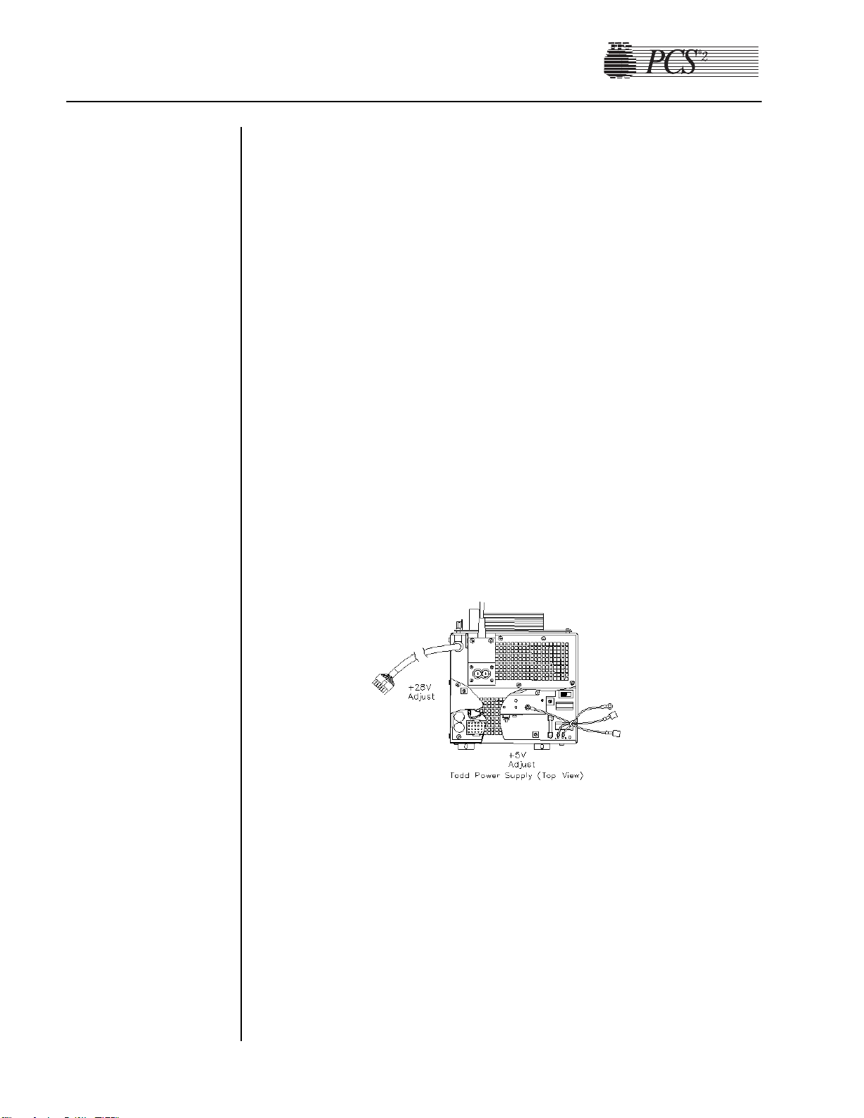
Note: The labeling of P507 test points located on the backplane card are
for reference in this illustration and do not appear on the backplane
card.
2. If calibration is required, the removal of the cage cover is necessary to
gain access to the power supply trim pots. To remove the cage cover
you must first remove the middle and left Phillips head screws on the
top of the cage where the two piece cage comes together. Then
remove the two screws on the bottom of the cage. Pull the half of the
cage closest to the rear of the machine straight out the back of the
machine.
3. To calibrate the power supply voltages, connect a voltmeter to the
appropriate pin at P507 on backplane board and measure the +5 VDC
supply. Adjust the +5V trim pot and the “R29” on the power supply
board, to +5.1 VDC. The trim pot is closest to the rear of the machine
on right hand side. Etched on the board next to the correct pot is
“R29” and the words “5V Adj.” All other voltages, except the 28
VDC, will track the 5 volt supply. Although no adjustments can be
made to the other voltages, please check and verify that they are
within their respective specification. Voltages that cannot be brought
within their respective tolerances indicate a problem with the power
supply or the loads on that supply.
4. To calibrate the 28V supply output, connect a voltmeter to the
appropriate test point of P507 and record the measured voltage. To
adjust the 28V supply, locate R9 on the power supply board, which is
located towards the middle of the board between two black coils
(approximately 2 inches behind J1).
4-2 PCS2 Service Manual
Figure 4-2, Todd Power Supply (top view)
Page 52

Chapter 4, Calibration 4-3
Condor Power Supply
Note: Use the following calibration procedure if the unit has a Condor
power supply assembly installed (P/N 48895-00).
1. Measure the power supply voltages at P507 on the backplane Card
(see Figure 4-1). Use pin seven for DC common/ground.
Note: Pins 1 thru 7 are all common/ground.
2. To calibrate the power supply voltages, adjust the +5V trim pot on the
front panel of the power supply. All other voltages will track the 5 volt
power supply. Although no adjustments can be made to the other
voltages, please check and verify that they are within their respective
specifications as described in Figure 4-1.
1. Power on the PCS2 in the Diagnostic mode of operation. The PCS2
must be powered on for a minimum of 15 consecutive minutes to
stabilize the optic circuit before proceeding with calibration. When 15
minutes have elapsed, remove the rear panel.
2. Inspect the optic window for contamination and clean it before
measuring the optics signal.
3. Remove the gray card from the envelope in the Gray Card
Replacement Kit.
4. Make a note of the Correction Factor written on the back of the gray
card.
Figure 4-3, Condor Power Supply (front view)
Bowl Optics
Signal
Page 53

5. Insert the gray card into the optic alignment fixture so that the arrow
on the back points up into the optic fixture.
Note: • If the optic alignment fixture has a gray card installed, remove
the gray card and discard. The gray card used in the optic
alignment fixture must be uncontaminated by light or material.
• Ensure the white backing of the gray card is not “yellow.”
• Ensure the gray measuring surface is not physically damaged.
• Ensure the gray card is less than one year older than the date
printed on the back of the card.
6. a) If adjusting the optics gain to a digital value, select the Transducer
test in Diagnostics.
b) If adjusting the optics gain to an analog voltage, connect a digital
voltage meter, (greater than 3½ digit resolution), to J105 (top plug)
pin 9 (signal) and pin 5 (ground) on the Processor Card.
7. Install the optics fixture ETD 5060 in the centrifuge and rotate it until
the optic beam is reflecting off the aiming dot on the fixture.
8. If the optic beam is not centered on the fixture aiming dot, loosen the
optic assembly, but leave snug with the (4) 4-40 keps nuts that secure
the optic assembly to the centrifuge. Slide the optic assembly up or
down, until the optic beam is centered on the dot, and tighten the keps
nuts.
9. Rotate the optic fixture until the optic beam is centered on the gray
card.
10. Close the centrifuge cover to allow the cover’s bowl collars to lock
around the optics fixture’s square alignment tabs.
11. Use the Correction Factor printed on the back of the gray card and the
formula below to calculate the optic gain to be calibrated. The PCS2
bowl optics calibration value is 2891 ± 25 digital units or +3.53 ±
0.03 VDC.
Use the following formula to determine the optic gain with Correction
Factor:
Optic
Digital
Gain to be Calibrated = Correction Factor x 2891 Digital Units
or
Optic
Voltage
Gain to be Calibrated = Correction Factor x 3.53 VDC
4-4 PCS2 Service Manual
Page 54

Chapter 4, Calibration 4-5
Example:
Calibrate the optics to 2891 digital units or +3.53 VDC:
Correction Factor printed on the back of the gray card = 0.829
Optic
Digital
Gain to be Adjusted = 0.829 x 2891 = 2397 digital units
or
Optic
Voltage
Gain to be Adjusted = 0.829 x 3.53 VDC = 2.926 VDC
Note: The bowl optics signal calibration range differs from the bowl
optics signal test (operational) range. The optics calibration range
is utilized to adjust the optics gain if it is found to be outside the
acceptable optic calibration test range.
12. Adjust the photoelectric transceiver to attain the desired optic value
determined from the calculation in step 11.
13. Remove the optics fixture from the centrifuge.
14. Adjust R24 potentiometer on the Processor Card until the average
optics offset value is 1 to 66 digital units (as displayed on the screen)
or 0.0 ± 0.08 VDC.
15. Replace the optics fixture in the centrifuge, rotating it until the optic
beam is centered on the gray card.
16. Close the centrifuge cover to allow the cover’s bowl collars to lock
around the optic fixture’s square alignment tabs.
17. Ensure the optic gain is within the specification range in step 11. Readjust if necessary.
18. Repeat the above steps until both the optics gain and offset are within
the specified ranges.
Note: When documenting the optics signal calibration value, ensure the
value recorded is the bowl optics calibration value, not the actual
gray card reading. In the above example in step 9, the value
recorded would be 2891 digital or +3.53 VDC.
Warning!
The Correction Factors used in the above calculation are example
values only. Each gray card is individually indexed and the
Correction Factor may vary for each card. The Correction Factor
from the actual card being used must be incorporated into the
optics signal calibration and testing calculations.
!
Page 55

1. Power on the PCS2 into the Utilities mode of operation by pressing
and holding the PLASMA key during power up until the Utilities
menu appears. The PCS2 must be powered on a minimum of 15
minutes before proceeding with this test.
2. Use the MODIFY PROGRAM key to select Diagnostics, then press
the DRAW key to execute Diagnostics.
3. Use the MODIFY PROGRAM key to select the Transducers test, then
press the DRAW key to execute the test.
4. Inspect the line sensor tubing channel for contamination and clean
before measuring voltage.
5. Remove the black access plug located on the front panel of the line
sensor.
6. Use a trim pot adjusting tool to set the line sensor signal to between
2866 - 3276.
7. Slide a black non-reflective surface into the line sensor tubing slot.
(Dull paper with dull black marker on both sides works well for this.)
Verify that the line sensor signal drops to between 0 and 103.
8. Adjust as necessary to satisfy both ranges.
9. Replace the black access plug in the line sensor.
10. Exit the transducers test by pressing the MODIFY PROGRAM key,
then exit Utilities by pressing the STOP key twice.
Cuff
1. Power on the PCS2 into the Utilities mode of operation by pressing
and holding the PLASMA key during power up until the Utilities
menu appears.
2. Select Calibration using the MODIFY PROGRAM and DRAW keys.
Toggle the write protect switch on the Processor Card when
instructed. (Remove rear access panel.)
3. Select A/D Calibration by pressing the DRAW key.
4. Ensure nothing is plugged into the cuff connector on the rear access
panel.
5. Press the DRAW key to store the cuff Offset value.
6. Prepare a cuff adapter by disconnecting the two sections of cuff
tubing. Plug a sphygmomanometer into the section which connects to
the cuff connector.
7. Plug the cuff adapter into the cuff connector on the rear access panel.
8. Start the cuff compressor by pressing the CUFF key.
9. Use the YES and NO keys to adjust the cuff output pressure to 100
mmHg and reads on the sphygmomanometer.
10. Press the RETURN key to store the cuff Full Scale value.
11. Stop the cuff compressor by pressing the CUFF key.
12.Remove the sphygmomanometer from the cuff tubing and reassemble
the cuff.
4-6 PCS2 Service Manual
A/D
Line Sensor
Signal
Page 56

Chapter 4, Calibration 4-7
13. Exit A/D Calibration by pressing the STOP key, then exit Calibration
by pressing the STOP key again. Toggle the write protect switch on
the Processor Card when instructed to, then replace the rear access
panel. Pay particular attention to prevent disconnection or kinking of
the pneumatic lines around the compressor and the cuff connector.
14. Exit Utilities by pressing the STOP key.
Weigher
PN 36924-00 Weigher Arm
Note: Use the following calibration procedure if the unit has a
PN 36924-00 Weigher Arm installed.
1. Power on the PCS2 into the Utilities mode of operation by pressing
and holding the PLASMA key during power up until the Utilities
menu appears.
2. Select the Calibration mode by pressing the DRAW key. Toggle the
“write protect” switch on the Processor Card when instructed.
(Remove rear panel access.)
3. Select the A/D Calibration by pressing the DRAW key.
4. Select the Weigher by pressing the MODIFY key once until the cursor
is pointing to Weigher.
5. Extend the weigher arm out until it is perpendicular to the machine’s
chassis. (Ensure no weight is hanging on the arm.)
6. After the weigher Input value stabilizes, press the DRAW key to store
the Offset value. (Now both Offset and Input values should be equal.)
7. Hang a calibrated 1000 gram weight on the weigher arm.
8. Once the Input has stabilized, press the RETURN key to store the
weigher Full Scale value. (With 1000 gram weight installed, the Full
Scale and Input values should be equal.)
9. Remove the 1000 gram weight from the weigher arm.
10. Exit A/D Calibration by pressing the STOP key, and then exit
Calibration by pressing the STOP key again. Toggle the “write
protect” switch on the Processor Card when instructed, and then
replace the rear access panel. Pay particular attention to prevent
disconnection or kinking of the pneumatic lines around the
compressor and cuff connector.
11. Exit Utilities by pressing the STOP key.
Page 57

4-8 PCS2 Service Manual
PN 52025-00 Weigher Arm
Note: Use the following calibration procedure if the unit has a
PN 52025-00 Weigher Arm installed.
1. Power on the PCS2 into the Utilities mode of operation by pressing
and holding the PLASMA key during power up until the Utilities
menu appears.
2. Select the Calibration mode by pressing the DRAW key. Toggle the
“write protect” switch on the Processor Card when instructed.
(Remove rear panel access.)
3. Select the A/D Calibration by pressing the DRAW key.
4. Select the Weigher by pressing the MODIFY key once until the cursor
is pointing to Weigher.
5. Extend the weigher arm out until it is perpendicular to the machine’s
chassis. (Ensure no weight is hanging on the arm.)
6. After the weigher Input value stabilizes, press the DRAW key to store
the Offset value. (Now both Offset value and Input should be equal.)
7. Calibrate the weigher Full Scale value by following the appropriate
procedure below:
W
eigher Calibration When Using Collection Bottles
a) Suspend a calibrated 1000 gram weight from the center of the
bottle area by hanging the weight between the weigher arm fingers
using string or a rubber band of minimal weight and thickness.
Place the string or rubber band over the weigher arm fingers so
they are centered within the calibration notches. (See Figure 4-4
below.) The string or rubber band thickness should be small enough
to allow it to center within the calibration notches, but strong
enough to securely hold the weight.
1000 gram
weight
String or
rubber band
Calibration notch
Figure 4-4, PN 52025-00 Weigher Arm (Top View)
Page 58

Chapter 4, Calibration 4-9
Note: When using a 1000 gram weight that can be fit within the weigher
arm’s fingers, the weight may be positioned inside the arm’s
fingers, provided the weight’s neck is equal to or greater than that
of the collection bottle.
b) Once the Input has stabilized, press the RETURN key to store the
weigher Full Scale value. (Now both Full Scale and Input values
should be equal.)
W
eigher Calibration When Using Collection Bags
a) Suspend a calibrated 1000 gram weight centered between the bag
pins, using a string or rubber band of minimal weight and thickness
placed on both pins.
b) Once the Input has stabilized, press the RETURN key to store the
weigher Full Scale value. (Now both Full Scale and Input values
should be equal.)
W
eigher Calibration When Using Collection Bottles and Bags
When utilizing collection bottles and bags, the weigher should be
calibrated using the bottle calibration method (see above) or it can be
recalibrated to the specific type of collection device prior to its use.
8. Remove the 1000 gram weight from the weigher arm.
9. Exit A/D Calibration by pressing the STOP key, and then exit
Calibration by pressing the STOP key again. Toggle the “write
protect” switch on the Processor Card when instructed, then replace
the rear access panel. Pay particular attention to prevent disconnection
or kinking of the pneumatic lines around the compressor and cuff
connector.
10. Exit Utilities by pressing the STOP key.
DPM
1. Power on the PCS2 into the Utilities mode of operation by pressing
and holding the PLASMA key during power up until the Utilities
menu appears. The PCS2 must be powered on a minimum of 15
minutes before proceeding with calibration.
2. Select Calibration using the MODIFY PROGRAM and DRAW keys.
Toggle the write protect switch on the Processor Card when
instructed. (Remove rear access panel.)
3. Select A/D Calibration by pressing the DRAW key, then select DPM
by pressing the MODIFY PROGRAM key.
4. Press the DRAW key to store the DPM Offset value.
Page 59

4-10 PCS2 Service Manual
Centrifuge
5. Prepare an SPM/DPM pressure adapter by cutting a DPM/SPM filter
with four inches of tubing from a disposable set. Remove the nipple
from the sphygmomanometer and insert the filter tubing onto the
sphygmomanometer.
6. Install the filter onto the DPM and pressurize the sphygmomanometer
to 300 mmHg.
7. Press the RETURN key to store the DPM Full Scale value.
8. Remove the filter from the DPM.
9. Exit A/D Calibration by pressing the STOP key, then exit Calibration
by pressing the STOP key again. Toggle the write protect switch on
the Processor Card when instructed to, then replace the rear access
panel. Pay particular attention to prevent disconnection or kinking of
the pneumatic lines around the compressor and the cuff connector.
10. Exit Utilities by pressing the STOP key.
1. Power on the PCS2 into the Utilities mode of operation by pressing and
holding the PLASMA key during power up until the Utilities menu appears.
2. Select Calibration using the MODIFY PROGRAM and DRAW keys.
Toggle the write protect switch on the Processor Card when instructed
(remove rear access panel).
3. Select Centrifuge using the MODIFY PROGRAM and DRAW keys.
4. Install a bowl into the centrifuge.
5. Close and latch the centrifuge cover.
6. Press the DRAW key to start the centrifuge at a set speed of 8000 rpm.
7. Press the YES or NO keys to adjust the actual speed to 8000 ± 30
rpm. Each key press changes the outval value by one digit, resulting in
a new centrifuge speed. Wait five to ten seconds between key presses
to allow the centrifuge speed to stabilize.
8. If the centrifuge does not reach 8000 rpm, set outval to 255. Using the
potentiometer R68 on the Centrifuge Driver Card, increase speed until
the display reads 8200 rpm. Lower outval back down using YES/NO
keys until actual speed is 8000 ± 30.
Figure 4-5, Centrifuge Driver PCB
Centrifuge speed adjust
Page 60

Chapter 4, Calibration 4-11
9. Press the SAVE PROGRAM key to save the outval value and change
the centrifuge set speed to 3000 rpm.
10. Press the YES or NO keys to adjust the actual speed to 3000 ± 30
rpm. Each key press changes the outval value by one digit, resulting in
a new centrifuge speed. Wait five to ten seconds between key presses
to allow the centrifuge speed to stabilize.
11. Press the SAVE PROGRAM key to save the outval value (the
displayed outval value may change when the SAVE PROGRAM key
is pressed).
12. Press the RETURN key to cycle the centrifuge speed from 8000,
7000, 5650, 4800, and 3000. Verify that the actual speeds are within
100 rpm of the set speeds.
13. Press the MODIFY PROGRAM key to exit the Centrifuge
Calibration, then press the STOP key to exit Calibration. Toggle the
write protect switch on the Processor Card when instructed to, then
replace the rear access panel. Pay particular attention to prevent
disconnection or kinking of the pneumatic lines around the
compressor and the cuff connector.
14. Exit Utilities by pressing the STOP key.
1. Power on the PCS2 into the Utilities mode of operation by pressing
and holding the PLASMA key during power up until the Utilities
menu appears.
2. Remove filters or tubing from the DPM, then select Calibration using the
MODIFY PROGRAM and DRAW keys. Toggle the write protect switch
on the Processor Card when instructed. (Remove rear access panel.)
3. Select Safety System using the MODIFY PROGRAM and DRAW keys.
4. Press the DRAW key to save the new high value and verify that the
value is between 3260 – 4080.
5. Change the pressure status to low by pressing the SAVE PROGRAM
key.
6. Press the RETURN key to save the new low value and verify that the
value is between 1265 – 1620.
7. Exit Safety System Calibration by pressing the MODIFY PROGRAM
key, then exit Calibration by pressing the STOP key. Toggle the write
protect switch on the Processor Card when instructed to. Then replace
the rear access panel. Pay particular attention to prevent disconnection
or kinking of the pneumatic lines around the compressor and the cuff
connector.
8. Exit Utilities by pressing the STOP key.
Safety System
Page 61

Overall Cosmetic Check
1. Check shipping carton for any sign of damage.
2. Inspect PCS2, especially in areas where damage to the shipping
carton, if any, was found.
3. Inspect PCS2 cabinet and mounted assemblies for imperfections.
Internal W
orkmanship
1. Remove front and rear access panels to gain access to internal
components.
2. Check all electrical connections including ground straps.
3. Check all pneumatic lines for evidence of kinked lines.
4. Check for loose or missing mounting hardware.
Langua
ge Configuration
1. Power on the PCS2 in the Utilities mode of operation by pressing and
holding the PLASMA key while switching the power on. Hold the
PLASMA key until the Utilities menu appears on the display.
2. Select Configuration on the Utilities menu by pressing the MODIFY
PROGRAM key until the arrow points to Configuration, then press
the DRAW key. Toggle the write protect switch on the Processor Card
when instructed. (Remove rear access panel.)
3. Press the MODIFY PROGRAM key until the arrow points to
Language.
4. Select Language by pressing the DRAW key.
5. Press the MODIFY PROGRAM key until the arrow points to the
language desired.
6. Select the language by pressing the DRAW key.
7. Press the STOP key to exit Language Configuration
Chapter 5
Installation and Configuration
Initial
Inspection
Configuration
of Protocol
Parameters
Page 62

5-2 PCS2 Service Manual
8. Press the STOP key again to exit Configuration. Toggle the write
protect switch on the Processor Card when instructed, then replace the
rear panel.
9. Exit Utilities by pressing the STOP key.
Protocol Selection
1. Power on the PCS2 in the Utilities mode of operation by pressing and
holding the PLASMA key while switching the power on. Hold the
PLASMA key until the Utilities menu appears on the display.
2. Select Configuration on the Utilities menu by pressing the MODIFY
PROGRAM key until the arrow points to Configuration, then press
the DRAW key. Toggle the write protect switch on the Processor Card
when instructed. (Remove rear access panel.)
3. Press the MODIFY PROGRAM key until the arrow points to
Protocols.
4. Select Protocols by pressing the DRAW key.
The following graphic represents the Protocol Selection screen.
ACCESSIBLE PROTOCOLS
→∗
PPP WITHOUT SALINE COMP.
PPP WITH SALINE COMP.
PPP AND LEUKOCYTE
PPP WITH SALINE & CLOSED SET
PRESS YES/NO TO TOGGLE
Note: Protocols with an asterisk next to them will be available to the
operator before each procedure. The PPP and Leukocyte Protocol is
used to collect leukocytes in addition to plasma. The PPP with
Saline and Closed Set Protocol is designed to be used with a
“closed set” disposable set and will return saline after each cycle.
This should not be used in the Source Plasma application.
5. Use the MODIFY PROGRAM key to move the arrow to the desired
protocol.
6. Press the YES key to select a desired protocol. (This makes the
selected protocol available to the operator.)
7. Press the NO key to deselect a desired protocol. (This makes the
deselected protocol unavailable to the operator.)
The following table has been included to aid centers in the protocol
configuration of their machines.
Page 63

Chapter 5, Installation and Configuration 5-3
Center Protocol Select
Always reinfuse saline PPP with Saline Comp.
Never reinfuse saline PPP without Saline Comp.
Sometimes reinfuse saline PPP with Saline Comp.
PPP without Saline Comp.
8. When all desired protocols are selected, press the STOP key to exit
Protocol Configuration.
9. Press the STOP key again to exit Configuration. Toggle the write
protect switch on the Processor Card when instructed, and replace the
rear panel.
10.Exit Utilities by pressing the STOP key.
Machine Settings
Note: Machine settings do not require configuration unless the RS232
port is being utilized with an external communications device.
1. Power on the PCS2 in the Utilities mode of operation by pressing and
holding the PLASMA key while switching the power on. Hold the
PLASMA key until the Utilities menu appears on the display.
2. Select Configuration on the Utilities menu by pressing the MODIFY
PROGRAM key until the arrow points to Configuration, then press
the DRAW key. Toggle the write protect switch on the Processor Card
when instructed. (Remove rear access panel.)
3. Press the MODIFY PROGRAM key until the arrow points to
Machine.
4. Select Machine by pressing the DRAW key.
5. Set the RS232 Board Type by using the YES and NO keys. The
machine defaults to “Standard.” Leave the setting at Standard unless
further instructed. Press the MODIFY PROGRAM key after the
RS232 Board has been selected.
6. Set the RS232 Device by using the YES and NO keys. The setting
options are: Network, Disk Drive or Printer. This setting does not
require configuration unless one of the three configurable external
devices are being utilized. Press the MODIFY PROGRAM key after
the RS232 Device has been selected.
7. Set the RS232 Baud Rate by using the YES and NO keys. This Baud
Rate defaults to 19200. This setting is dependent on the type of
RS232 Device being utilized and does not require configuration if no
external RS232 Device is being used.
8. Press the STOP key to exit Machine Settings.
Page 64

5-4 PCS2 Service Manual
9. Press the STOP key again to exit Configuration. Toggle the write
protect switch on the Processor Card when instructed and replace the
rear panel.
10.Exit Utilities by pressing the STOP key.
Serial Number Configuration
1. Power on the PCS2 in the Utilities mode of operation by pressing and
holding the PLASMA key while switching the power on. Hold the
PLASMA key until the Utilities menu appears on the display.
2. Select Configuration on the Utilities menu by pressing the MODIFY
PROGRAM key until the arrow points to Configuration, then press
the DRAW key. Toggle the write protect switch on the Processor Card
when instructed. (Remove rear access panel.)
3. Press the MODIFY PROGRAM key until the arrow points to Serial #.
4. Select Serial # by pressing the DRAW key.
The following graphic represents the Serial # screen:
MACHINE SERIAL #
Machine SERIAL # 00A000
^
5. Use the “YES” and “NO” keys to change the digit or character
selected, as indicated by the “^” cursor. Use the “MODIFY” key to
advance the cursor to the next digit/character. Change all digits or
characters until the display serial number matches the machine serial.
6. Press the STOP key to exit Serial # Configuration.
7. Press the STOP key again to exit Configuration. Toggle the write
protect switch on the Processor Card when instructed and replace the
rear panel.
8. Exit Utilities by pressing the STOP key.
Collection W
eight Configuration
1. Power on the PCS2 in the Utilities mode of operation by pressing and
holding the PLASMA key while switching the power on. Hold the
PLASMA key until the Utilities menu appears on the display.
2. Select Configuration on the Utilities menu by pressing the MODIFY
PROGRAM key until the arrow points to Configuration, then press
the DRAW key. Toggle the write protect switch on the Processor Card
when instructed. (Remove rear access panel.)
Page 65

Chapter 5, Installation and Configuration 5-5
3. Press the MODIFY PROGRAM key until the arrow points to Draw
Cycle.
4. Select Draw Cycle by pressing the DRAW key.
5. Set the LOW weight by using the YES key to increase and the NO
key to decrease the weight. Press the MODIFY PROGRAM key when
the desired LOW weight has been reached.
6. Set the MID weight by using the YES key and NO key. Press the
MODIFY PROGRAM key when the desired MID weight has been
reached.
7. Set the HIGH weight by using the YES key and NO key. Press the
MODIFY PROGRAM key when the desired HIGH weight has been
reached. The screen will then display the “Suction Compens. wt.”
setting; leave the setting at 1.
8. Press the MODIFY PROGRAM key to set the Plasma Unit of
Measurement to the desired setting. Press the YES key to select
Volume and the NO key to select “Weight” (The default value is
Weight). Proceed to Step 10 if “Weight” is selected.
9. Press the MODIFY PROGRAM key after selecting “Volume” to set
the Plasma Density [%]. Use the YES and NO key to set the Plasma
Density [%] in accordance to the center SOP (The default value is
1026).
10.Press the MODIFY PROGRAM key until Duration in Statistics is
displayed. Use the YES key to ENABLE and the NO key to DISABLE
(The default value is Enable). Selecting ENABLE will display the
procedure time in the Procedure Statistics Screen.
11.Press the STOP key to exit Draw Cycle Configuration.
12.Press the STOP key again to exit Configuration. Toggle the write
protect switch on the Processor Card when instructed, and then replace
the rear panel.
13. Exit Utilities by pressing the STOP key.
Bowl Configuration
1. Power on the PCS2 in the Utilities mode of operation by pressing and
holding the PLASMA key while switching the power on. Hold the
PLASMA key until the Utilities menu appears on the display.
2. Select Configuration on the Utilities menu by pressing the MODIFY
PROGRAM key until the arrow points to Configuration, then press
the DRAW key. Toggle the write protect switch on the Processor Card
when instructed (remove rear access panel).
3. Press the MODIFY PROGRAM key until the arrow points to HS
Bowl, then press the DRAW key
4. Press the MODIFY PROGRAM key until HS Bowl is displayed. Use
the Yes key to ENABLE and the NO key to DISABLE (The default is
Disable).
Page 66

5. Press the STOP key to exit HS Bowl.
6. Press the STOP key again to exit Configuration. Toggle the write
protect switch on the Processor Card when instructed, and then
replace the rear panel.
7. Exit Utilities by pressing the STOP key.
Valves T
est
1. Power on the PCS2 into the Utilities mode of operation by pressing
and holding the PLASMA key during power up until the Utilities
menu appears.
2. Select Diagnostics on the Utilities menu by pressing the MODIFY
PROGRAM key until the arrow points to Diagnostics, then press the
DRAW key.
3. Select the Valves test by using the MODIFY PROGRAM key to move
the arrow to “Valves” test and the DRAW key to execute.
4. Open all three valves by pressing the SALINE, PLASMA, and CUFF
keys.
5. Insert tubing from a PCS2 harness set, LN 620, into each valve and
press the DRAW key to start cycling the valves.
6. Allow valves to cycle for at least one minute, then press the STOP
key. Verify that at the end of one minute, no errors have accumulated
in the error log. If errors exist, determine which valve is causing the
error by running the cycle test again. Isolate problem to power
(Eng./De-eng.) position switch (Open/Closed), or valve current (Highcurrent). Refer to Chapter 6, Troubleshooting.
7. Exit the Valves test by pressing the MODIFY PROGRAM key.
Weigher Test
1. Power on the PCS2 in the Utilities mode of operation by pressing and
holding the PLASMA key while switching the power on. Hold the
PLASMA key until the Utilities menu appears on the display.
2. Select Diagnostics on the Utilities menu by pressing the MODIFY
PROGRAM key until the arrow points to Diagnostics, then press the
DRAW key.
3. Be sure the weigher arm is fully extended with nothing hanging on it.
Select the weigher test on the Diagnostics menu by pressing the
MODIFY PROGRAM key, then press the DRAW key.
4. Verify the displayed weight is ZERO ±1.
5. Hang the following calibrated weights on the weigher and verify that
the displayed weight is within the defined specification.
• 1000 ± 5 grams
5-6 PCS2 Service Manual
Testing
Page 67

Chapter 5, Installation and Configuration 5-7
6. Remove the weights and verify that the displayed weight returns to
ZERO ±1.
7. If calibration is required, refer to Chapter 4.
8. Exit the weigher test by pressing the MODIFY PROGRAM key.
DPM Sensor Test
1. Be sure no filters are connected to the DPM and SPM. Select the
Pressure test using the MODIFY PROGRAM and DRAW keys.
Note: List Number 06002-110-NA machines do not have the SPM.
2. Verify that the DPM offset is within the range of 1984 to 2112. If out
of range, DPM may need to be replaced.
3. Grasp the DPM white luer plunger and twist counterclockwise while
sliding in the plunger. Verify both interlock switch status indicators
change to IN. Release the plunger and verify that both indicators
return to OUT.
4. Grasp the DPM white luer plunger and twist clockwise while sliding
in the plunger. Verify both interlock switch status indicators change to
IN. Release the plunger and verify that both indicators return to OUT.
5. Install a DPM filter with about 4" of tubing onto the DPM. Connect a
calibrated sphygmomanometer or equivalent device to the filter
tubing. Pressurize the DPM to 300 mmHg and verify that the
displayed pressure reading is within the range of 292 to 308 mmHg.
6. If calibration is required, refer to Chapter 4.
Cuff T
est
1. Install a cuff adaptor tubing with a sphygmomanometer (or
equivalent) attached into the rear panel cuff connector.
2. Turn the cuff compressor on by pressing the CUFF key.
3. Verify the cuff inflates to 50 ± 5 mmHg.
4. Use the YES key to increase the cuff pressure to 100.
5. Verify the cuff inflates to100 ± 10 mmHg.
6. If calibration is required, refer the Chapter 4, Calibration.
Exit the Pressure test by pressing the MODIFY PROGRAM key.
Display Test
1. Select the Display test using the MODIFY PROGRAM and DRAW keys.
2. Verify that all pixels are lit on display, then press DRAW.
3. Verify that a character set is displayed and no characters are deformed
or missing.
4. Exit the Display test by pressing the MODIFY PROGRAM key.
Page 68

Keyboard Test
1. Select the Keyboard test using the MODIFY PROGRAM and DRAW
keys.
2. Press each key (save MODIFY PROGRAM key for last) and verify
that LED extinguishes (if equipped) and Key Pressed value indicates
the correct key name.
3. Press the MODIFY PROGRAM key to exit the Keyboard test.
Centrifuge Testing
Fluid Sensor T
est
1. Select the Centrifuge test in Diagnostics using the MODIFY
PROGRAM and DRAW keys.
2. Open the centrifuge cover and place a moist paper towel or cotton
swab on the fluid sensor located in the centrifuge well. Verify that the
SPILL value changes to TRUE.
3. Remove moisture and wipe dry. Verify that the SPILL value changes
to FALSE.
Centrifuge Cover & Lock Function Test
1. Close centrifuge cover and slowly rotate the cover lock until the
COVER value changes from UNLOCKED to LOCKED. Verify that
the cover knob can be turned an additional 3/8" to 5/8" after the cover
lock switches activate.
2. If adjustment is required, refer to the Chapter 2, Machine Part
Replacement Reference.
Centrifuge Speed and Bowl Vibration Test
1. Install a bowl partially filled with water (approximately 2/3 full) into
the centrifuge. Close and lock the centrifuge cover.
2. Start the centrifuge by pressing the DRAW key. Verify the Centrifuge
Speed stabilizes to 7000 ± 100 rpm.
3. If calibration is required, refer to Chapter 4, Calibration.
4. As the centrifuge is spinning, observe the air/water interface in the
bowl and listen for any signs of centrifuge contract with the chassis.
Verify that the air/water interface never becomes discontinuous,
indicating excessive vibration.
5. If excessive vibration or noise is observed, refer to the Machine Part
Replacement Chapter to realign the centrifuge.
6. Press the STOP key to stop the centrifuge and remove the bowl from
the centrifuge.
7. Exit the centrifuge test by pressing the MODIFY PROGRAM key.
5-8 PCS2 Service Manual
Page 69

Chapter 5, Installation and Configuration 5-9
Donor Lights Test
1. Select the Donor Lights test using the MODIFY PROGRAM and
DRAW keys.
2. Verify that all LEDs light and extinguish when instructed.
3. Exit the Donor Lights test by pressing the MODIFY PROGRAM key.
Line Sensor T
est
1. Be sure the PCS2 has been powered on for at least 15 minutes before
proceeding with this test.
2. Select the Transducers test using the MODIFY PROGRAM and
DRAW keys.
3. Verify that no tubing is installed in the line sensor, and that the digital
reading for the line sensor signal is between 2866 and 3276.
4. Slide a black non-reflective surface into the line sensor tubing slot.
(Dull paper with dull black marker on both sides works well for this)
Verify that the line sensor signal drops to between 0 and 103.
5. If calibration is required, refer to Chapter 4.
Bowl Optics Signal Test
1. Be sure the PCS2 has been powered on for at least 15 minutes before
proceeding with this test.
2. Select the Transducer test using the MODIFY PROGRAM and
DRAW keys.
3. Inspect the optic window for contamination and clean before
measuring the optics signal.
4. Remove the gray card from the envelope in the Gray Card
Replacement Kit.
5. Make a note of the Correction Factor written on the back of the gray
card.
6. Insert the gray card into the optic alignment fixture so that the arrow
on the back points up into the optic fixture.
Note: If the optic alignment fixture has a gray card installed, remove the
gray card and discard. The gray card used in the optic alignment
fixture must be uncontaminated by light or material.
Ensure the white backing of the gray card is not “yellow.”
Ensure the gray measuring surface is not physically damaged.
Ensure the gray card is less than one year older than the date
printed on the back of the card.
7. a) If testing the optics signal to a digital value, select the Transducer
test in Diagnostics.
Page 70

b) If testing the optics signal to an analog voltage, connect a digital
voltage meter, (greater than 3½ digit resolution), to J105 (top plug)
pin 9 (signal) and pin 5 (ground) on the Processor Card.
8. Ensure the centrifuge chuck is empty. Verify the average analog or
digital reading for the bowl optics offset signal is between 1 and 82
digital units or -0.10 to +0.10 Vdc.
9. Install the optic fixture ETD 5060 in the centrifuge and rotate it until
the optic beam is centered on the gray card.
10.Close the centrifuge cover to allow the cover’s bowl collars to lock
around the optic fixture’s square alignment tabs.
11.Make a note of the actual digital or analog voltage optic gray card
reading.
12.Use the Correction Factor printed on the back of the gray card and the
formula below to calculate the optic gain being measured. Ensure the
calculated optic reading with Correction Factor is between 2295 and
3278 digital units or +2.8 to 4.0 Vdc.
Use the following formula to determine the optic gain with Correction
Factor:
Optic
Digital
Gain with Correction Factor = Actual Digital Gray Card Reading ÷
Correction Factor
or
Optic
Voltage
Gain with Correction Factor = Actual Optic Gray Card Reading
(Vdc) ÷ Correction Factor
Example:
The actual gray card reading is 2397 digital units or 2.926 Vdc
The Correction Factor on the back of the gray card = 0.829
Optic
Digital
Gain with Correction Factor = 2397 ÷ 0.829 = 2891 digital units
or
Optic
Voltage
Gain with Correction Factor = 2.926 Vdc ÷ 0.829 = 3.53 Vdc
13.If calibration is required, refer to the Bowl Optics Signal Calibration in
Chapter 4.
Note: The bowl optics signal test (operational) range described above
differs from the bowl optics signal calibration range in the
Calibration Chapter. The optics calibration range is utilized to
adjust the optics gain if it is found to be outside the acceptable optic
calibration test range.
5-10 PCS2 Service Manual
Page 71

Chapter 5, Installation and Configuration 5-11
When documenting the optic signal value, ensure the voltage
recorded is the calculated optic signal value, not the actual gray
card reading. In the above example in step 11, the optic signal value
recorded would be 2891 digital or +3.53 Vdc.
Warning!
The Correction Factors used in the above calculations are example
values only. Each gray card is individually indexed and the
Correction Factor may vary for each card. The Correction Factor
from the actual card being used must be incorporated into the
optics signal calibration and testing calculations.
Air Detector T
est
1. Select the Air Detector test using the MODIFY PROGRAM and
DRAW keys.
2. Place fluid-filled tubing in air detector under test as requested, verify
that the air detector LED lights, and press the DRAW key as
requested.
3. Repeat test for each air detector as asked. When the last air detector
has been tested, a screen will appear showing the status of the four air
detector signals. Confirm that each air detector can see fluid and air
by inserting a piece of fluid-filled tubing into each air detector while
monitoring the Polled and Latched signals.
4. If an air detector fails the testing, refer to the Troubleshooting
Chapter.
5. Exit the Air Detector test by pressing the MODIFY PROGRAM key.
PCS2 Functional Test
1. Exit Utilities by pressing the STOP key. The PCS2 will reboot and
execute the system start-up sequence. Respond to any questions or
warning as the test progresses. Select a new procedure if prompted.
2. Ensure a cuff is installed in the rear panel connector and all four
exhaust fans are operating and blowing air out of the rear panel.
3. Lock and unlock centrifuge cover as prompted.
4. Verify the PCS2 advances to the Weigher Test screen. With no weight
on the weigher, verify the displayed weight is ZERO ± 1 gram. If it is
outside this range, press the DRAW key to tare the weigher. Hang a
1000g calibrated weight on the weigher. Verify the displayed weight
is 1000 ± 5 grams.
5. Remove the weight and verify the displayed weight returns to ZERO
± 1 gram.
!
Page 72

6. Press the YES key and verify the Install Disposable screen is
displayed.
7. At Install Disposable screen perform the following:
• Install partially water-filled bowl in the centrifuge and lock the
centrifuge cover.
• Install a DPM filter in the DPM
• Floss a segment of clear LN620 harness tubing through the line
sensor.
Verify the PCS2 display advances to the Load Pump/Test Centrifuge
screen.
8. Press the PRIME key and verify the following:
• Both pumps turn clockwise for a few seconds, then stop.
• The centrifuge spins for a few seconds, then stops.
9. Press the YES key and verify the Plasma Collection Weight Selection
screen is displayed.
10.Press the MODIFY key and verify the Saline Substitution screen is
displayed.
Note: This screen will only be displayed is the saline option is
programmed. If the saline option is not programmed, verify the
PRIME screen is displayed and proceed to step 12.
11.Press the NO key and verify the PRIME screen is displayed.
12.Install fluid-filled tubing in the AC, DLAD1 and DLAD2 and then
press the PRIME key. Verify machine advances to the Ready screen.
13.Install fluid-filled tubing in the BLAD.
14.Press the Draw key and verify the both pump are turning clockwise,
the centrifuge is spinning and the cuff inflates. Also verify the donor
and plasma valves open.
15.After a few moments, the 'No Pressure Change At DPM' message will
be displayed, press the DRAW key to continue.
16.Observe the air/water interface in the bowl as the centrifuge is
spinning and listen for any signs of the centrifuge contacting the
cabinet. Verify the air/water interface never becomes discontinuous,
indicating excessive vibration.
17.Press the STOP key. Verify the centrifuge and both pumps stop and all
valves close.
18.Press the RETURN key and verify the End Procedure Option screen is
displayed.
19.Press the YES key and verify the blood pump turns counterclockwise
and the AC pump is not turning. Also verify the donor valve opens
immediately and the plasma valve opens shortly thereafter.
20.Press the STOP key after a few moments and verify the Ready is
displayed.
21.Press the STOP key again and verify the Abort Procedure screen is
displayed.
5-12 PCS2 Service Manual
Page 73

Chapter 5, Installation and Configuration 5-13
22.Press the YES key to abort the procedure and verify the Abort
Procedure Confirmation screen is displayed.
23.Press the DRAW key to abort the procedure and verify the Procedure
Statistics screen is display.
24.Remove the test disposable set and verify the machine advances to the
Systems Test screen.
Leakage Current
1. Plug the PCS2 into the Leakage Tester (Dale Technologies LT544D
Lite or equivalent).
2. Plug the Leakage Tester into a grounded electrical outlet.
3. Set the meter switch settings as follows:
• Leakage
• Neutral Closed
• Polarity Normal
4. Turn on the PCS2.
5. Note the reading in microamperes on the meter.
6. Depress the GND switch on the meter.
7. Change the Polarity switch from Normal to Reverse.
8. Verify the readings do not exceed 100 microamperes at 120 VAC and
500 microamperes at 240 VAC.
Gr
ound Continuity
1. Change the meter mode to RESISTANCE.
2. Plug the ground wire (coiled wire with clip) into the grounding socket
on the Leakage Meter.
3. Attach the clip to the following exposed metal locations. Verify that
there is continuity.
• Pump - rotor screws
• Rear Panel hardware
• Front panel hardware
• Pinch valve plungers
4. Verify the highest reading is less than 1 Ohm.
Page 74

Source Plasma Customers Only
When machines are transferred between center locations, calibration
testing and configuration should be performed prior to placing the
machines into service. The calibration testing and configuration steps
outlined in Chapter 5, excluding Leakage Current and Ground Continuity,
should be performed. The testing and configuration must be performed at
the center it is being transferred to. The PCS2 Machine Transfer
Verification Sheet, on page 5-15, should be completed and kept in the
center’s machine log.
5-14 PCS2 Service Manual
Machine
Transfers
Page 75

Chapter 5, Installation and Configuration 5-15
PCS2 Machine Transfer Verification Form
Customer Name: City/State:
PCS-2 Serial #
VALVES Functional Yes No
WEIGHER Zero Reading
0 gm ± 1
1000 gm ± 5
PRESSURE DPM Offset (1984 - 2112)
300 mmHg ± 8
CUFF 50 mmHg ± 5
100 mmHg ± 10
DISPLAY Functional Yes No
KEYBOARD Functional Yes No
CENTRIFUGE SPEED Set Speed Actual Speed
7000 RPM ± 100
Cover Lock Functional Yes No
Bowl Vibration Functional Yes No
Spill Detect Functional Yes No
Donor Lights Functional Yes No
TRANSDUCERS OPTICS Aim (Yes if Adjusted) Yes No
Open (1-82 or 0 V ± 0.10)
Grey Card
(2295- 3278 or 2.8 - 4.0 V)
LINE SENSOR Open (2866 - 3276)
Black (0-103)
AIR DETECTOR ACAD Functional Yes No
BLAD Functional Yes No
DLAD-1 Functional Yes No
DLAD-2 Functional Yes No
FANS Functional Yes No
Biohazardous Waste Bag Attached Yes No
Program Revision
Cuff
Weigher
Circle if adjusted DPM
Centrifuge
Optics Voltage
Line Sensor
Performed by: Print Name:
Date:
Page 76

Chapter 6
Troubleshooting
The purpose of this chapter is to provide troubleshooting assistance for
solving problems associated with the PCS2. The scope of this chapter
focuses on solving electrical, mechanical, and performance related
problems.
Note: When troubleshooting machines, it is helpful to use parts from a
working PCS2 unit to verify faults and isolate the questionable
component. Once the faulty component is isolated, notify the
Haemonetics Hot Line at 800-356-3506. If at all possible,
Haemonetics recommends the substitute part be returned to the
original machine.
The PCS2 operating protocols use refined technologies which rely on
many variables to function. If possible, procure PCS2 operational training
before investigating system performance or product quality issues.
The messages reported by the PCS2 are very specific and provide useful
diagnostic information about the problem. There are over 100 diagnostic
messages which can be generated by the processor card, and several
hundred combinations of safety fault codes which can be generated by the
safety card. Most hardware or electrical failures will be reported by one
system or the other.
The inventory of messages the PCS2 has to report information to the user
is vast. This functionality is an important diagnostic tool when trying to
understand a problem.
MESSAGES
Page 77

6-2 PCS2 Service Manual
Status messages are alerts that indicate that attention is needed to resolve
an operational problem. Status messages usually do not indicate that a
malfunction has occurred, but in some cases a status message that cannot
be cleared is an indication of a malfunction. An example is a centrifuge
cover latch that passes the system start-up tests, but during operation
causes a message that cannot be cleared requesting the cover to be
latched. This chapter lists status messages which could be displayed if a
hardware failure occurs, but do not usually mean that a hardware failure
has occurred. These status messages are listed along with the CPU
generated error messages.
Error messages are generally categorized in one of two groups: those
which are CPU generated messages, and those which are safety system
generated messages.
By design, the CPU should always detect problems before the safety
system does. In most cases, the fact that the safety system reports the
problem indicates that the CPU is experiencing some type of problem.
Exceptions are state faults caused by improper valve position, or pump
speed and direction problems. In rare cases, the safety system may
respond quicker than the CPU.
A CPU generated message has a text description and is usually
accompanied by a code number. The code number provides a reference to
the problem resolution section of this chapter. The machine operator may
not recall the complete text, but if the code number is noted, the complete
text message can be found in this manual.
CPU generated error messages resemble the following example:
LINE SENSOR VOLTAGE TOO LOW
CODE = 50
PLEASE POWER OFF.
Press YES for Procedure Stats
Error
Messages
Status
Messages
Page 78

A safety system generated error message does not have a text description.
Instead, five safety system registers report information in hexadecimal
format.
Safety system generated error messages resemble this example, where
each XXXXXX represents a hexadecimal code:
The CPU generated error messages are listed on the following pages in
numerical order for those that have associated error codes. The remaining
status and error messages are listed alphabetically. The messages are
accompanied by a brief description of the message, and then followed by
resolution steps to alleviate the problem.
Chapter 6, Troubleshooting 6-3
CPU Error
Messages
SAFETY SYSTEM FAULT DETECTION
COMMAND: XXXXXX
CHANNEL 1 CHANNEL 2
FAULT: XXXXXX XXXXXX
CRITICAL: XXXXXX XXXXXX
PLEASE RECORD THESE VALUES
Press NO to Mute Safety Alarm
Press YES to Resume Procedure
Page 79

✍
Notes
✍
6-4 PCS2 Service Manual
Page 80

CODE TEXT MESSAGE DESCRIPTION SUGGESTED RESOLUTION
Chapter 6, Troubleshooting 6-5
4
5
7
9
10
10
CPU OPERATION
ERROR
ROM TEST
FAILURE
CALIBRATION
CRC FAILURE
AIR DETECTOR
FAULT (ACAD,
BLAD, DLAD1, OR
DLAD2)
DPM FAILED 20%
ANALOG TEST
DPM FAILED 50%
ANALOG TEST
CPU opcodes or
registers are not
operating correctly.
ROM CRC does not
match value stored in
NVRAM.
Calibration CRC
does not match value
stored in NVRAM.
Air detector does not
sense air during
system start-up air
detector test.
DPM channel of A/D
converter failed 20%
analog voltage load
test.
DPM channel of A/D
converter failed 50%
analog voltage load
test.
1. Replace processor card. Using Utilities, calibrate all the
components under A/D, centrifuge, safety system, and
configure the language. Reset protocol parameters
(MODIFY key), if parameters were different from
default values.
1. Replace ROM IC (Main program IC).
1. Recalibrate the A/D, centrifuge, and safety system.
2. Replace processor card. Using Utilities, calibrate all the
components under A/D, centrifuge, and safety system,
and configure the language. Reset protocol parameters
(MODIFY key), if parameters were different from
default values.
1. Use air detector test in Diagnostics to verify problem.
2. Check, repair, or replace all electrical connections
associated with the failed air detector.
3. Replace the failed air detector.
4. Replace CPU PCB. Using Utilities, calibrate all
components under A/D, centrifuge, and safety system
and configure the language. Reset protocol parameters
(MODIFY key) if parameters were different from
default values.
1. Replace processor card. Using Utilities, calibrate all the
components under A/D, centrifuge, safety system, and
configure the language. Reset protocol parameters
(MODIFY key), if parameters were different from
default values.
2. Replace weigher load cell and calibrate in A/D in
Utilities.
1. Replace processor card. Using Utilities, calibrate all the
components under A/D, centrifuge, safety system, and
configure the language. Reset protocol parameters
(MODIFY key), if parameters were different from
default values.
2. Replace weigher load cell and calibrate in A/D in
Utilities.
Page 81

6-6 PCS2 Service Manual
CODE TEXT MESSAGE DESCRIPTION SUGGESTED RESOLUTION
10
11
11
11
12
DPM FAILED 80%
ANALOG TEST
SPM FAILED 20%
ANALOG TEST
SPM FAILED 50%
ANALOG TEST
SPM FAILED 80%
ANALOG TEST
DONOR VALVE
POSITION FAULT
PLASMA VALVE
POSITION FAULT
SALINE VALVE
POSITION FAULT
DPM channel of A/D
converter failed 80%
analog voltage load
test.
SPM channel of A/D
converter failed 20%
analog voltage load
test.
SPM channel of A/D
converter failed 50%
analog voltage load
test.
SPM channel of A/D
converter failed 80%
analog voltage load
test.
Donor valve position
switch indicates that
valve did not
transition.
Plasma valve position
switch indicates that
valve did not
transition.
Saline valve position
switch indicates that
valve did not
transition.
1. Replace processor card. Using Utilities, calibrate all the
components under A/D, centrifuge, safety system, and
configure the language. Reset protocol parameters
(MODIFY key), if parameters were different from
default values.
2. Replace weigher load cell and calibrate in A/D in
Utilities.
1. Replace processor card. Using Utilities, calibrate all the
components under A/D, centrifuge, safety system, and
configure the language. Reset protocol parameters
(MODIFY key), if parameters were different from
default values.
1. Replace processor card. Using Utilities, calibrate all the
components under A/D, centrifuge, safety system, and
configure the language. Reset protocol parameters
(MODIFY key), if parameters were different from
default values.
1. Replace processor card. Using Utilities, calibrate all the
components under A/D, centrifuge, safety system, and
configure the language. Reset protocol parameters
(MODIFY key), if parameters were different from
default values.
1. Use the valve test in Diagnostics to manually transition
valves and monitor the valve and switch response.
2. Swap valve connections at top deck distribution card to
isolate problem to valve or circuit.
3. If valve does not move, check, repair or replace all
connections associated with the appropriate valve drive
circuit.
4. Replace valve, driver card, or processor card. Using
Utilities, calibrate all the components under A/D,
centrifuge, safety system, and configure the language.
Reset protocol parameters (MODIFY key), if parameters
were different from default values.
5. If valve does move but is not recognized, check, repair,
or replace all connections associated with the appropriate
valve position switch or replace the valve.
6. Replace driver or processor card. Using Utilities,
calibrate all the components under A/D, centrifuge,
safety system, and configure the language. Reset
protocol parameters (MODIFY key), if parameters were
different from default values.
Page 82

CODE TEXT MESSAGE DESCRIPTION SUGGESTED RESOLUTION
Chapter 6, Troubleshooting 6-7
13
15
16
DONOR VALVE
CURRENT FAULT
PLASMA VALVE
CURRENT FAULT
SALINE VALVE
CURRENT FAULT
WATCHDOG
ERROR
WATCHDOG
ERROR
Donor valve current
sense circuit indicates
that current did not
transition high or
low.
Plasma valve current
sense circuit indicates
that current did not
transition high or
low.
Saline valve current
sense circuit indicates
that current did not
transition high or
low.
Safety system relay
did not open during
system start-up
watchdog test.
Safety system relay
did not close during
system start-up
watchdog test.
1. Use the valve test in Diagnostics to manually transition
valves and monitor the valve and switch response.
2. Swap valve connections at the top deck distribution card
to isolate problem to valve or circuit.
3. Replace driver card.
4. Replace processor card. Using Utilities, calibrate all the
components under A/D, centrifuge, safety system, and
configure the language. Reset protocol parameters
(MODIFY key), if parameters were different from
default values.
1. Replace driver card.
2. Replace safety card.
3. Replace processor card. Using Utilities, calibrate all the
components under A/D, centrifuge, safety system, and
configure the language. Reset protocol parameters
(MODIFY key), if parameters were different from
default values.
1. Replace driver card.
2. Replace safety card.
3. Replace processor card. Using Utilities, calibrate all the
components under A/D, centrifuge, safety system, and
configure the language. Reset protocol parameters
(MODIFY key), if parameters were different from
default values.
Page 83

6-8 PCS2 Service Manual
CODE TEXT MESSAGE DESCRIPTION SUGGESTED RESOLUTION
17
19
20
21
22
23
WATCHDOG
ERROR
LOW PRESSURE
ERROR
LOW PRESSURE
ERROR
LOW PRESSURE
ERROR
LOW PRESSURE
ERROR
LOW PRESSURE
ERROR
Safety system did not
post fault to register
during system startup watchdog test.
Safety system relay
did not open during
system start-up low
pressure test.
Safety system relay
did not close during
system start-up low
pressure test.
Safety system did not
post fault to register
during system startup low pressure test.
DPM low pressure
load test produced a
value that is out of
the range of 1265 -
1620.
DPM low pressure
load test produced a
value that was ± 7%
from calibrated
value.
1. Replace safety card.
2. Replace processor card. Using Utilities, calibrate all the
components under A/D, centrifuge, safety system, and
configure the language. Reset protocol parameters
(MODIFY key), if parameters were different from
default values.
1. Replace driver card.
2. Replace safety card.
1. Replace driver card.
2. Replace safety card.
1. Replace safety card.
2. Replace processor card. Using Utilities, calibrate all the
components under A/D, centrifuge, safety system, and
configure the language. Reset protocol parameters
(MODIFY key), if parameters were different from
default values.
1. Using Diagnostics in Utilities, load the DPM for low
pressure and measure the DPM signal at P502 pin 1 of
the backplane card. Acceptable range for low reading is
1.54 - 1.98 VDC (1265 - 1620). If analog voltage
exceeds range, replace DPM.
2. Replace processor card. Using Utilities, calibrate all the
components under A/D, centrifuge, safety system, and
configure the language. Reset protocol parameters
(MODIFY key), if parameters were different from
default values.
1. Recalibrate the safety system in Utilities and verify that
low pressure digital reading is between (1265 - 1620). If
digital reading is out of range or grossly fluctuating,
replace DPM.
2. Replace processor card. Using Utilities, calibrate all the
components under A/D, centrifuge, safety system, and
configure the language. Reset protocol parameters
(MODIFY key), if parameters were different from
default values.
Page 84

CODE TEXT MESSAGE DESCRIPTION SUGGESTED RESOLUTION
Chapter 6, Troubleshooting 6-9
25
26
27
28
29
31
HIGH PRESSURE
ERROR
HIGH PRESSURE
ERROR
HIGH PRESSURE
ERROR
HIGH PRESSURE
ERROR
HIGH PRESSURE
ERROR
CHANNEL 1
STATE ERROR
Safety system relay
did not open during
system start-up high
pressure test.
Safety system relay
did not close during
system start-up high
pressure test.
Safety system did not
post fault to register
during system startup high pressure test.
DPM high pressure
load test produced a
value that is out of
the range of 3260 -
4080.
DPM high pressure
load test produced a
value that was ± 7%
from calibrated
value.
Safety system relay
did not open during
system start-up
Channel 1 state test.
1. Replace driver card.
2. Replace safety card.
1. Replace driver card.
2. Replace safety card.
1. Replace the safety card.
2. Replace processor card. Using Utilities, calibrate all the
components under A/D, centrifuge, safety system, and
configure the language. Reset protocol parameters
(MODIFY key), if parameters were different from
default values.
1. Using Diagnostics in Utilities, load the DPM for high
pressure and measure the DPM signal at P502 pin 1 of
the backplane card. Acceptable range for high reading is
3.98 - 4.98 VDC (3260 - 4080). If analog voltage
exceeds range, replace DPM.
2. Replace processor card. Using Utilities, calibrate all the
components under A/D, centrifuge, safety system, and
configure the language. Reset protocol parameters
(MODIFY key), if parameters were different from
default values.
1. Recalibrate the safety system in Utilities and verify that
high pressure digital reading is between (3260 - 4080). If
the digital reading is out of range, replace DPM.
2. Replace processor card. Using Utilities, calibrate all the
components under A/D, centrifuge, safety system, and
configure the language. Reset protocol parameters
(MODIFY key), if parameters were different from
default values.
1. Replace driver card.
2. Replace safety card.
Page 85

6-10 PCS2 Service Manual
CODE TEXT MESSAGE DESCRIPTION SUGGESTED RESOLUTION
32
33
34
36
37
38
39
CHANNEL 1
STATE ERROR
CHANNEL 1
STATE ERROR
CHANNEL 2
STATE ERROR
(AIR STATE TEST)
CHANNEL 2
STATE ERROR
CHANNEL 2
STATE ERROR
CHANNEL 2
STATE ERROR
CHANNEL 2
STATE ERROR
(AIR STATE TEST)
Safety system relay
did not close during
system start-up
Channel 1 state test.
Safety system did not
post fault to register
during system startup Channel 1 state
test.
Safety system did not
respond to air signal
during system start-up
Channel 1 and 2 air
detector state test.
Safety system relay
did not open during
system start-up
Channel 2 state test.
Safety system relay
did not close during
system start-up
Channel 2 state test.
Safety system did not
post fault to register
during system startup Channel 2 state
test.
Safety system relay
did not open during
system start-up
Channel 1 and 2 air
detector state test.
1. Replace driver card.
2. Replace safety card.
1. Replace safety card.
2. Replace processor card. Using Utilities, calibrate all
components under A/D, centrifuge, safety system, and
configure the language. Reset protocol parameters
(MODIFY key), if parameters were different from
default values.
1. Replace safety card.
1. Replace driver card.
2. Replace safety card.
1. Replace driver card.
2. Replace safety card.
1. Replace safety card.
2. Replace processor card. Using Utilities, calibrate all the
components under A/D, centrifuge, safety system, and
configure the language. Reset protocol parameters
(MODIFY key), if parameters were different from
default values.
1. Replace driver card.
2. Replace safety card.
Page 86

Chapter 6, Troubleshooting 6-11
CODE TEXT MESSAGE DESCRIPTION SUGGESTED RESOLUTION
40
41
43
44
45
47
48
CHANNEL 2
STATE ERROR
(AIR STATE TEST)
CHANNEL 2
STATE ERROR
(AIR STATE TEST)
CHANNEL 1 TIME
BASE ERROR
CHANNEL 1 TIME
BASE ERROR
CHANNEL 1 TIME
BASE ERROR
CHANNEL 2 TIME
BASE ERROR
CHANNEL 2 TIME
BASE ERROR
Safety system relay
did not close during
system start-up
Channel 1 and 2 air
detector state test.
Safety system did not
post fault to register
during system start-up
Channel 1 and 2 air
detector state test.
Safety system relay
did not open during
system start-up
Channel 1 time base
test.
Safety system relay
did not close during
system start-up
Channel 1 time base
test.
Safety system did not
post fault to register
during system startup Channel 1 time
base test.
Safety system relay
did not open during
system start-up
Channel 2 time base
test.
Safety system relay
did not close during
system start up
Channel 2 time base
test.
1. Replace driver card.
2. Replace safety card.
1. Replace safety card.
2. Replace processor card. Using Utilities, calibrate all the
components under A/D, centrifuge, safety system, and
configure the language. Reset protocol parameters
(MODIFY key), if parameters were different from
default values.
1. Replace driver card.
2. Replace safety card.
1. Replace driver card.
2. Replace safety card.
1. Replace safety card.
1. Replace driver card.
2. Replace safety card.
1. Replace driver card.
2. Replace safety card.
Page 87

6-12 PCS2 Service Manual
CODE TEXT MESSAGE DESCRIPTION SUGGESTED RESOLUTION
49
50
51
52
CHANNEL 2 TIME
BASE ERROR
LINE SENSOR
VOLTAGE TOO
LOW
LINE SENSOR
VOLTAGE TOO
HIGH
CONFIGURATION
CRC FAILURE
Safety system did not
post fault to register
during system startup Channel 2 time
base test.
Line sensor voltage
level is less than
acceptable value after
confirming sensor is
clean and no tubing is
installed (2252) (2.75
VDC).
Line sensor voltage
level is greater than
acceptable value after
confirming sensor is
clean and no tubing is
installed. (3890)
(4.75 VDC).
Configuration CRC
does not match value
stored in NVRAM.
1. Replace safety card.
2. Replace processor card. Using Utilities, calibrate all the
components under A/D, centrifuge, safety system, and
configure the language. Reset protocol parameters
(MODIFY key), if parameters were different from
default values.
1. Use Utilities to display the line sensor digital voltage in
Diagnostics under transducers. Measure the analog line
sensor voltage to gnd at J105 pin 8 on the processor card.
Divide the digital reading by 819 to convert to analog
voltage.
2. If converted digital voltage equals measured analog
voltage, calibrate the digital line sensor voltage to 2866 3276 (3.75 ± 0.25 VDC) by adjusting trim pot located
inside line sensor. (Remove access hole plug.) If line
sensor cannot be calibrated, replace line sensor.
3. If voltages differ significantly, replace processor card.
Using Utilities, calibrate all the components under A/D,
centrifuge, safety system, and configure the language.
Reset protocol parameters (MODIFY key), if parameters
were different from default values.
1. Use Utilities to display the line sensor digital voltage in
Diagnostics under transducers. Measure the analog line
sensor voltage to gnd at J105 pin 8 on the processor card.
Divide the digital reading by 819 to convert to analog
voltage.
2. If converted digital voltage equals measured analog
voltage, calibrate the digital line sensor voltage to 2866 3276 (3.75 ± 0.25 VDC) by adjusting trim pot located
inside line sensor (remove access hole plug). If line
sensor cannot be calibrated, replace line sensor.
3. If voltages differ significantly, replace processor card.
Using Utilities, calibrate all the components under A/D,
centrifuge, safety system, and configure the language.
Reset protocol parameters (MODIFY key), if parameters
were different from default values.
1. Reconfigure the language in Utilities.
2. Replace processor card. Using Utilities, calibrate all the
components under A/D, centrifuge, safety system, and
configure the language. Reset protocol parameters
(MODIFY key), if parameters were different from
default values.
Page 88

Chapter 6, Troubleshooting 6-13
CODE TEXT MESSAGE DESCRIPTION SUGGESTED RESOLUTION
53
54
102
Donor Valve Position
Fault
Plasma Valve
Position Fault
Saline Valve Position
Fault
Extended
Configuration Mode
Not Allowed During
Normal PCS2 Usage.
Remove Ext conf
jumper from J104
CENTRIFUGE
OVERSPEED
Indicated valve
position switch
indicates that valve is
in incorrect position.
The machine senses
that the jumper used
to gain access to the
extended
configuration
parameters has been
left in the machine.
Centrifuge encoder
signals indicate that
spindle speed is 300
rpm greater than set
speed.
1. Use the valve test in Diagnostics to manually transition
valves and monitor the valve and switch response.
2. Swap valve connections at top deck distribution card to
isolate problem to valve or circuit.
3. If valve does not move, check, repair or replace all
connections associated with the appropriate valve drive
circuit.
4. Replace valve, driver card, or processor card. Using
Utilities, calibrate all the components under A/D,
centrifuge, safety system, and configure the language.
Reset protocol parameters (MODIFY key), if parameters
were different from default values.
5. If valve does move but is not recognized, check, repair,
or replace all connections associated with the
appropriate valve position switch or replace the valve.
6. Replace driver or processor card. Using Utilities,
calibrate all the components under A/D, centrifuge,
safety system, and configure the language. Reset
protocol parameters (MODIFY key), if parameters were
different from default values.
1. Remove the extended configuration jumper from J104
on the processor Board.
2. Replace processor card. Using Utilities, calibrate all the
components under A/D, centrifuge, safety system and
configuration. Reset protocol parameters (MODIFY
key) if parameters were different from the default
values.
1. Using Utilities, display the centrifuge screen under
Diagnostics. Install bowl in centrifuge. Start centrifuge
and measure actual speed vs various set speeds. If
speeds are wrong, use calibration to calibrate centrifuge
speed.
2. If speed is wrong by a gross amount, set the centrifuge
set speed to 3000 rpm and measure the centrifuge
command + signal at P401 pin 18A (pin 17) on the
backplane card. Signal should be around +6.1 VDC. If
signal is wrong, replace the driver card.
3. Replace processor card. Using Utilities, calibrate all the
components under A/D, centrifuge, safety system, and
configure the language. Reset protocol parameters
(MODIFY key), if parameters were different from
default values.
4. If command + signal is OK, replace either the centrifuge
controller card or the centrifuge assembly.
Page 89

6-14 PCS2 Service Manual
CODE TEXT MESSAGE DESCRIPTION SUGGESTED RESOLUTION
103
108
200
CENTRIFUGE
UNDERSPEED
CENTRIFUGE NOT
RUNNING
BLOOD PUMP NO
SIGNAL
Centrifuge encoder
signals indicate that
spindle speed is 300
rpm less than set
speed.
Centrifuge encoder
signals indicate that
centrifuge did not
spin at all when
command was given
to run centrifuge.
Blood pump encoder
signals indicate that
pump is not moving
when in a running
state.
1. Check bowl installation for misaligned base, or check
that bowl seal is not binding by spinning bowl by hand
while holding bowl header stationary.
2. Using Utilities, display the centrifuge screen under
Diagnostics. Install bowl in centrifuge. Start centrifuge
and measure actual speed vs various set speeds. If speeds
are slightly wrong, use calibration to calibrate speed.
3. If speed is wrong by a gross amount, set the centrifuge
set speed to 3000 rpm and measure the centrifuge
command + signal at P401 pin 18A (pin 17) on the
backplane card. Signal should be around +6.1 VDC. If
signal is wrong, replace the driver card.
4. If signal is still wrong, replace processor card. Using
Utilities, calibrate all the components under A/D,
centrifuge, safety system, and configure the language.
Reset protocol parameters (MODIFY key), if parameters
were different from default values.
5. If command + signal is OK, replace either the centrifuge
controller card or the centrifuge assembly.
1. Check bowl for frozen header.
2. Check +48 volt supply.
3. Check, repair, or replace all electrical connections
associated with the centrifuge drive circuit.
4. Using Utilities, display the centrifuge screen under
Diagnostics. Install bowl in centrifuge. Start centrifuge
and measure actual speed vs various set speeds.
5. If centrifuge does not spin at all, measure the centrifuge
command + signal at P401 pin 18A (pin 17) on the
backplane card. Signal should be around +6.1 VDC. If
signal is wrong, replace the driver card.
6. If signal is still wrong, replace processor card. Using
Utilities, calibrate all the components under A/D,
centrifuge, safety system, and configure the language.
Reset protocol parameters (MODIFY key), if parameters
were different from default values.
7. If command + signal is OK, replace either the centrifuge
controller card or the centrifuge assembly.
1. Check, repair, or replace all electrical connections
associated with the pump drive circuit.
2. Swap motor and encoder plugs at top deck distribution
card to isolate problem.
3. Measure +28 volt pulse modulated signal across pump
drive connector P616 on the top deck distribution card
while attempting to run pump. If no signal, replace driver
card or processor card.
4. If signal exists, replace pump motor.
Page 90

CODE TEXT MESSAGE DESCRIPTION SUGGESTED RESOLUTION
Chapter 6, Troubleshooting 6-15
201
202
203
204
205
AC PUMP NO
SIGNAL
BLOOD PUMP TOO
SLOW
BLOOD PUMP TOO
FAST
AC PUMP TOO
FAST
RATIO FAULT
TOO LOW
AC pump encoder
signals indicate that
pump is not moving
when in a running
state.
Blood pump encoder
signals indicate that
pump is moving
slower than set speed.
Blood pump encoder
signals indicate that
pump is moving
faster than set speed.
AC pump encoder
signals indicate that
pump is moving
faster than set speed.
Blood and AC pump
encoder signals
indicate that pump
ratio is lower than set
ratio.
1. Check, repair, or replace all electrical connections
associated with the pump drive circuit.
2. Swap motor and encoder plugs at top deck distribution
card to isolate problem.
3. Use Diagnostics to run pumps. Measure +28 volt pulse
modulated signal across pump drive connector P614 on
the top deck distribution card while attempting to run
pump. If no signal, replace driver card or processor card.
4. If signal exists, replace pump motor.
1. Swap motor and encoder plugs at top deck distribution
card to isolate problem.
2. Replace pump motor, or driver or processor card. If
CPU, recalibrate A/D, centrifuge, and safety system, and
reconfigure the language in Utilities. Reset protocol
parameters (MODIFY key), if parameters were different
from default values.
1. Swap motor and encoder plugs at top deck distribution
card to isolate problem.
2. Replace pump motor, or driver or processor card. If
CPU, recalibrate A/D, centrifuge and safety system, and
reconfigure the language in Utilities. Reset protocol
parameters (MODIFY key), if parameters were different
from default values.
Page 91

6-16 PCS2 Service Manual
CODE TEXT MESSAGE DESCRIPTION SUGGESTED RESOLUTION
206
207
208
209
210
RATIO FAULT
TOO HIGH
AC PUMP WRONG
DIRECTION
BLOOD PUMP
WRONG
DIRECTION
AC PUMP
POSITION FAULT
BLOOD PUMP
POSITION FAULT
Blood and AC pump
encoder signals
indicate that pump
ratio is higher than
set ratio.
AC pump encoder
signals indicate that
pump is moving in
wrong direction.
Blood pump encoder
signals indicate that
pump is moving in
wrong direction.
Driver board
indicates that AC
pump position is 128
counts ahead or
lagging behind set
pump position.
Driver board
indicates that blood
pump position is 128
counts ahead or
lagging behind set
pump position.
1. Swap motor and encoder plugs at top deck distribution
card to isolate problem.
2. Replace pump motor, or driver or processor card. If
CPU, recalibrate A/D, centrifuge, and safety system, and
reconfigure the language in Utilities. Reset protocol
parameters (MODIFY key), if parameters were different
from default values.
1. Swap motor and encoder plugs at top deck distribution
card to isolate problem.
2. Replace pump motor, or driver or processor card. If
CPU, recalibrate A/D, centrifuge, and safety system, and
reconfigure the language in Utilities. Reset protocol
parameters (MODIFY key), if parameters were different
from default values.
Note: In some cases this message may be the result of flow
problems, improperly loaded harness, kinks or improperly
seated pump rotor.
1. Swap motor and encoder plugs at top deck distribution
card to isolate problem.
2. Replace pump motor, or driver or processor card. If
CPU, recalibrate A/D, centrifuge, and safety system, and
reconfigure the language in Utilities. Reset protocol
parameters (MODIFY key), if parameters were different
from default values.
1. Swap motor and encoder plugs at top deck distribution
card to isolate problem.
2. Replace pump motor, or driver or processor card. If
CPU, recalibrate A/D, centrifuge, and safety system and
reconfigure the language in Utilities. Reset protocol
parameters (MODIFY key), if parameters were different
from default values.
Page 92

CODE TEXT MESSAGE DESCRIPTION SUGGESTED RESOLUTION
Chapter 6, Troubleshooting 6-17
502
504
507
SPM FILTER
INTERLOCK
FAILURE
DPM / SPM FILTER
INTERLOCK
FAILURE
DPM FILTER
INTERLOCK
FAILURE
50 second time-out
has occurred after
request to remove
SPM filter. Before
troubleshooting, be
sure filter was
removed within 50
seconds of displayed
request.
50 second time-out
has occurred after
request to remove
DPM & SPM filters.
Before
troubleshooting, be
sure filters were
removed within 50
seconds of displayed
request.
50 second time-out
has occurred after
request to remove
DPM filter. Before
troubleshooting, be
sure filter was
removed within 50
seconds of displayed
request.
1. If request to remove filter remains displayed after
removing SPM filter from SPM within 50 seconds,
check, repair, or replace all electrical connections
associated with the SPM.
2. Use Diagnostics to check SPM interlocks. Check that
filter sleeve is properly installed in SPM and that the
filter interlocks respond properly when the filter sleeve
is twisted clockwise and counterclockwise. Replace
SPM if problem is found. Use Utilities to recalibrate
A/D and safety system.
3. Replace processor card. Using Utilities, calibrate all the
components under A/D, centrifuge, safety system, and
configure the language. Reset protocol parameters
(MODIFY key), if parameters were different from
default values.
1. If request to remove filters remains displayed after
removing DPM and SPM filters from DPM and SPM
within 50 seconds, check, repair, or replace all electrical
connections associated with the DPM and SPM.
2. Use Diagnostics to check DPM and SPM interlocks.
Check that filter sleeve is properly installed in DPM and
SPM and that the filter interlocks respond properly when
the filter sleeve is twisted clockwise and
counterclockwise. Replace DPM and SPM if problem is
found. Use Utilities to recalibrate A/D and safety system.
3. Replace processor card. Using Utilities, calibrate all the
components under A/D, centrifuge, safety system, and
configure the language. Reset protocol parameters
(MODIFY key), if parameters were different from
default values.
1. If request to remove filter remains displayed after
removing DPM filter from DPM within 50 seconds,
check, repair, or replace all electrical connections
associated with the DPM.
2. Use Diagnostics to check DPM interlocks. Check that
filter sleeve is properly installed in DPM and that the
filter interlocks respond properly when the filter sleeve
is twisted clockwise and counterclockwise. Replace
DPM if problem is found. Use Utilities to recalibrate
A/D and safety system.
3. Replace processor card. Using Utilities, calibrate all the
components under A/D, centrifuge, safety system, and
configure the language. Reset protocol parameters
(MODIFY key), if parameters were different from
default values.
Page 93

6-18 PCS2 Service Manual
CODE TEXT MESSAGE DESCRIPTION SUGGESTED RESOLUTION
509
510
511
512
AIR DETECTOR
FAULT (ACAD)
AIR DETECTOR
FAULT (BLAD)
AIR DETECTOR
FAULT (DLAD1)
AIR DETECTOR
FAULT (DLAD2)
ACAD does not
sense air during
system start-up air
detector test.
BLAD does not sense
air during system
start-up air detector
test.
DLAD1 does not
sense air during
system start-up air
detector test.
DLAD2 does not
sense air during
system start-up air
detector test.
1. Use air detector test in Diagnostics to verify problem.
2. Check, repair, or replace all electrical connections
associated with the ACAD.
3. Replace ACAD air detector.
4. Replace processor card. Using Utilities, calibrate all the
components under A/D, centrifuge, safety system, and
configure the language. Reset protocol parameters
(MODIFY key), if parameters were different from
default values.
1. Use air detector test in Diagnostics to verify problem.
2. Check, repair, or replace all electrical connections
associated with the BLAD.
3. Replace BLAD air detector.
4. Replace processor card. Using Utilities, calibrate all the
components under A/D, centrifuge, safety system, and
configure the language. Reset protocol parameters
(MODIFY key), if parameters were different from
default values.
1. Use air detector test in Diagnostics to verify problem.
2. Check, repair, or replace all electrical connections
associated with the DLAD1.
3. Replace DLAD1 air detector.
4. Replace processor card. Using Utilities, calibrate all the
components under A/D, centrifuge, safety system, and
configure the language. Reset protocol parameters
(MODIFY key), if parameters were different from
default values.
1. Use air detector test in Diagnostics to verify problem.
2. Check, repair, or replace all electrical connections
associated with the DLAD2.
3. Replace DLAD2 air detector.
4. Replace processor card. Using Utilities, calibrate all the
components under A/D, centrifuge, safety system, and
configure the language. Reset protocol parameters
(MODIFY key), if parameters were different from
default values.
Page 94

CODE TEXT MESSAGE DESCRIPTION SUGGESTED RESOLUTION
Chapter 6, Troubleshooting 6-19
514
515
516
DPM OUT OF
TOLERANCE
SPM OUT OF
TOLERANCE
CUFF OUT OF
TOLERANCE
DPM offset (ambient
pressure) is outside
of acceptable range
(1902 - 2194) (2.32 -
2.68 VDC).
SPM offset (ambient
pressure) is outside
of acceptable range
(1902 - 2194) (2.32 -
2.68 VDC).
Cuff offset (ambient
pressure) is greater
than acceptable value
after confirming cuff
is removed (190)
(0.23 VDC).
1. Check, repair, or replace all electrical connections
associated with the DPM.
2. Measure DPM signal offset (at ambient pressure) at
P502 pin 1 on the backplane card or check in
Diagnostics. If it is not 2.32 - 2.68 VDC or 1902 - 2194,
replace DPM. Recalibrate DPM in A/D and safety
system in Utilities.
3. Replace processor card. Using Utilities, calibrate all the
components under A/D, centrifuge, safety system, and
configure the language. Reset protocol parameters
(MODIFY key), if parameters were different from
default values.
1. Check, repair or replace all electrical connections
associated with the SPM. The SPM may be electrically
disconnected from the Top Deck PCB if found to be the
source of the problem.
2. Measure DPM signal offset (at ambient pressure) at
P502 pin 1 on the backplane card or check in
Diagnostics. If it is not 2.32 - 2.68 VDC or 1902 - 2194,
replace DPM. Recalibrate DPM in A/D and safety
system in Utilities.
3. Replace processor card. Using Utilities, calibrate all the
components under A/D, centrifuge, safety system, and
configure the language. Reset protocol parameters
(MODIFY key), if parameters were different from
default values.
1. Check, repair, or replace all electrical connections
associated with the cuff.
2. Check cuff offset in Diagnostics and verify problem.
3. Replace front panel distribution card and calibrate cuff
in A/D in Utilities.
4. Replace processor card. Using Utilities, calibrate all the
components under A/D, centrifuge, safety system, and
configure the language. Reset protocol parameters
(MODIFY key), if parameters were different from
default values.
Page 95

6-20 PCS2 Service Manual
CODE TEXT MESSAGE DESCRIPTION SUGGESTED RESOLUTION
517
701
702
800
WEIGHER OUT OF
TOLERANCE
CPU RELAY
CLOSING
FAILURE
CPU RELAY
OPENING
FAILURE
SOFTWARE
WATCHDOG
FAULT
****NO FLOW****
Weigher offset is
greater than
acceptable value after
confirming all weight
is removed (175)
(0.21 VDC).
CPU relay fails to
close during system
start-up test.
CPU relay fails to
open during system
start-up test.
CPU did not execute
required steps
resulting in watchdog
time-out.
Pump set speeds have
decremented to zero
due to low pressure
measurement by
DPM.
1. Check, repair, or replace all electrical connections
associated with the weigher.
2. Check weigher offset in Diagnostics and verify the
problem.
3. Replace weigher load cell and calibrate weigher in A/D
in Utilities.
4. Replace processor card. Using Utilities, calibrate all the
components under A/D, centrifuge, safety system, and
configure the language. Reset protocol parameters
(MODIFY key), if parameters were different from
default values.
1. Replace driver card.
2. Replace processor card. Using Utilities, calibrate all the
components under A/D, centrifuge, safety system, and
configure the language. Reset protocol parameters
(MODIFY key), if parameters were different from
default values.
1. Replace driver card.
2. Replace processor card. Using Utilities, calibrate all the
components under A/D, centrifuge, safety system, and
configure the language. Reset protocol parameters
(MODIFY key), if parameters were different from
default values.
1. Replace the processor card. Using Utilities, calibrate all
the components under A/D, centrifuge, safety system,
and configure the language. Reset protocol parameters
(MODIFY key), if parameters were different from
default values.
1. This is a normal message if pressure from the donor is
low and is possibly caused by a flow restriction.
2. Use Diagnostics to check the DPM calibration.
3. Replace DPM. Use Utilities to calibrate DPM and SPM
in A/D screen, and safety system screen for DPM only.
Page 96

CODE TEXT MESSAGE DESCRIPTION SUGGESTED RESOLUTION
Chapter 6, Troubleshooting 6-21
AIR DETECTED
EARLY
AIR DETECTED IN
BLOOD LINE
AIR IN AC LINE
BLAD air signal
indicates air before
220 ml plus plasma
return volume has
been pumped from
bowl.
BLAD air signal
indicates air when
fluid is expected, 25
ml after Draw began.
ACAD air signal
indicates air when
fluid is expected.
1. Use air detector test in Diagnostics to confirm the
problem.
2. Check, repair, or replace all electrical connections
associated with the BLAD air detector.
3. With fluid-filled tubing installed in the air detector,
measure the (+5 VDC fluid, 0 VDC air) BLAD signal at
P502 pin 31 on the backplane card. If no signal, replace
BLAD air detector.
4. Replace processor card. Using Utilities, calibrate all the
components under A/D, centrifuge, safety system, and
configure the language. Reset protocol parameters
(MODIFY key), if parameters were different from
default values.
1. Use air detector test in Diagnostics to confirm problem.
2. Check, repair, or replace all electrical connections
associated with the ACAD air detector.
3. If fluid is present in tubing and tubing is installed in the
air detector, measure the (+5 VDC fluid, 0 VDC air)
ACAD signal at P502 pin 29 on the backplane card. If
no signal, replace ACAD air detector.
4. Replace processor card. Using Utilities, calibrate all the
components under A/D, centrifuge, safety system, and
configure the language. Reset protocol parameters
(MODIFY key), if parameters were different from
default values.
Page 97

6-22 PCS2 Service Manual
CODE TEXT MESSAGE DESCRIPTION SUGGESTED RESOLUTION
AIR IN DONOR
LINE 1
AIR IN DONOR
LINE 2
ARRAY BOUNDS
ERROR
DLAD 1 air signal
indicates air when
fluid is expected.
DLAD 2 air signal
indicates air when
fluid is expected.
An internal software
error has occurred,
where an item was
accessed beyond a
defined array.
1. Use air detector test in Diagnostics to confirm problem.
2. Check, repair, or replace all electrical connections
associated with the DLAD1 air detector.
3. If fluid is present in tubing and tubing is installed in the
air detector, measure the (+5 VDC fluid, 0 VDC air)
DLAD1 signal at P503 pin 2 on the backplane card. If no
signal, replace DLAD1 air detector.
4. Replace processor card. Using Utilities, calibrate all the
components under A/D, centrifuge, safety system, and
configure the language. Reset protocol parameters
(MODIFY key), if parameters were different from
default values.
1. Use air detector test in Diagnostics to confirm the
problem.
2. Check, repair, or replace all electrical connections
associated with the DLAD2 air detector.
3. If fluid is present in tubing and tubing is installed in the
air detector, measure the (+5 VDC fluid, 0 VDC air)
DLAD2 signal at P503 pin 4 on the backplane card. If no
signal, replace DLAD2 air detector.
4. Replace processor card. Using Utilities, calibrate all the
components under A/D, centrifuge, safety system, and
configure the language. Reset protocol parameters
(MODIFY key), if parameters were different from
default values.
1. Check +5 VDC power supply.
2. Replace processor card. Using Utilities, calibrate all the
components under A/D, centrifuge, safety system, and
configure the language. Reset protocol parameters
(MODIFY key), if parameters were different from
default values.
Page 98

CODE TEXT MESSAGE DESCRIPTION SUGGESTED RESOLUTION
Chapter 6, Troubleshooting 6-23
CENTRIFUGE
COVER
UNLOCKED PLEASE LOCK
CENTRIFUGE
COVER
DIVISION BY
ZERO
DRAW CYCLE
TOO LONG PRESS RETURN TO
CONTINUE
FLUID HAS BEEN
DETECTED IN THE
CENTRIFUGE
WELL DISCONTINUE
PROCEDURE AND
CLEAN THE
CENTRIFUGE
WELL
Centrifuge cover
latch switches
indicate that cover is
open or unlocked
beginning or during
Draw.
Computer executed a
division by zero
command.
Blood pump encoder
signals indicate that
draw volume has
exceeded acceptable
limit (690 ml).
Spill detector signal
indicates that fluid
has been detected in
the centrifuge well.
1. Check that centrifuge cover halves are closed
completely and that bowl header is aligned properly in
centrifuge cover halves. Listen for two distinctive clicks
from microswitches when cover latch knob secures the
cover halves.
2. Close and latch the cover halves and measure +28 VDC
on P404 pin 2 and +15 VDC on P404 pin 3 of the
centrifuge distribution card. If no signal exists, check
alignment of centrifuge cover latch microswitches and
adjust accordingly.
3. If signal exists, but CPU is not responding, check,
repair, or replace all electrical connections associated
with the centrifuge cover switch signals.
4. Replace processor card. Using Utilities, calibrate all the
components under A/D, centrifuge, safety system, and
configure the language. Reset protocol parameters
(MODIFY key), if parameters were different from
default values.
1. Check +5 volt supply.
2. Replace processor card. Using Utilities, calibrate all the
components under A/D, centrifuge, safety system, and
configure the language. Reset protocol parameters
(MODIFY key), if parameters were different from
default values.
1. This is a common message if the hematocrit of donor’s
blood is below 35, or if the blood pump efficiency is
negatively affected by a flow restriction or some
problem with the pump rotor.
2. Conduct a flow test on the blood pump. Replace blood
pump rotor if efficiency is less than acceptable value.
1. Using Utilities, display the centrifuge screen under
Diagnostics and monitor the spill detector signal labeled
SPILL. “TRUE means fluid is sensed, “FALSE” means
no fluid is sensed. Wipe the spill detector with a dry
cloth while monitoring spill signal.
2. Measure +10 VDC fluid sensor signal at P406 pin 1. If
signal is present and sensor is dry, replace fluid sensor
assembly.
3. If signal is 0 VDC and SPILL = TRUE, replace
processor card. Using Utilities, calibrate all the
components under A/D, centrifuge, safety system, and
configure the language. Reset protocol parameters
(MODIFY key), if parameters were different from
default values.
Page 99

6-24 PCS2 Service Manual
CODE TEXT MESSAGE DESCRIPTION SUGGESTED RESOLUTION
HIGH PRESSURE
IN DONOR LINE RELIEVE PRESS.
BEFORE
PHLEBOTOMY
ILLEGAL OPCODE
ERROR
NEGATIVE RTN
PRESSURE
OVERFLOW
ERROR
RETURN CYCLE
TOO LONG
DPM pressure
measurement exceeds
acceptable limit in
Ready mode (>100
mmHg).
Computer executed
an illegal instruction.
Computer is lost and
cannot execute
commands.
DPM pressure
measurement exceeds
acceptable limit
(<-40).
An internal
computational error
has occurred.
BLAD air signal
indicates fluid, after
bowl volume plus
plasma return volume
has been pumped
from bowl.
1. Check calibration of DPM in Diagnostics.
1. Check +5 volt supply.
2. Replace processor card. Using Utilities, calibrate all the
components under A/D, centrifuge, safety system, and
configure the language. Reset protocol parameters
(MODIFY key), if parameters were different from
default values.
1. This is a highly unusual message which may indicate an
intermittently defective DPM or A/D circuit. Check
calibration of DPM in Utilities.
2. Replace DPM and calibrate A/D and safety system in
Utilities.
3. Replace the processor card. Using Utilities, calibrate all
the components under A/D, centrifuge, safety system,
and configure the language. Reset protocol parameters
(MODIFY key), if parameters were different from
default values.
1. Check +5 VDC power supply voltage.
2. Replace the processor card. Using Utilities, calibrate all
the components under A/D, centrifuge,safety system, and
configure the language. Reset protocol parameters
(MODIFY key) if parameters were different from default
values.
1. If fluid still exists in the tubing and especially the bowl,
check for obstructions in the blood pump tubing or
effluent line, or for air in wrong bag. If no obstructions
exist, check the efficiency of the blood pump. Replace
blood pump rotor if efficiency is less than acceptable
value.
2. If no fluid exists in the tubing, the air detector did not
sense air. Replace the air detector.
Page 100

CODE TEXT MESSAGE DESCRIPTION SUGGESTED RESOLUTION
Chapter 6, Troubleshooting 6-25
SOFTWARE
WATCHDOG
FAULT - CURRENT
MODULE ID=X
EXPECTED
MODULE ID=X
CURRENT
STATE=X
SOFTWARE
WATCHDOG
FAULT - INVALID
STATE=X
SPM / DPM FILTER
IS NOT
INSTALLED PLEASE INSTALL
AND UNCLAMP IT
SPM FILTER IS
NOT INSTALLED PLEASE INSTALL
AND UNCLAMP IT
THE PROTOCOL
PARAMETERS
HAVE RESET TO
THEIR ORIGINAL
VALUES
CPU did not execute
required steps
resulting in watchdog
time-out.
CPU did not execute
required steps
resulting in watchdog
time-out.
DPM and SPM
interlock signals
indicate that DPM
and SPM filters are
not installed anytime
after system
initialization.
SPM interlock
signals indicate that
SPM filter is not
installed during Draw
or Return.
Protocol parameter
CRC does not match
value stored in
NVRAM.
1. Replace the processor card. Using Utilities, calibrate all
the components under A/D, centrifuge, safety system,
and configure the language. Reset protocol parameters
(MODIFY key), if parameters were different from
default values.
1. Replace the processor card. Recalibrate A/D, centrifuge
and safety system, and reconfigure the language in
Utilities. Reset protocol parameters (MODIFY key), if
parameters were different from default values.
1. Verify that white sleeves are fully seated.
2. Check, repair, or replace all electrical connections
associated with the DPM and SPM.
3. Replace DPM and SPM. Use Utilities to calibrate DPM
and SPM in A/D screen, and safety system screen for
DPM only.
4. Replace the processor card. Using Utilities, calibrate all
the components under A/D, centrifuge, safety system,
and configure the language. Reset protocol parameters
(MODIFY key), if parameters were different from
default values.
1. Verify that white sleeves are fully seated.
2. Check, repair, or replace all electrical connections
associated with the SPM.
3. Replace SPM. Use Utilities to calibrate SPM in the A/D
screen.
4. Replace the processor card. Using Utilities, calibrate all
the components under A/D, centrifuge, safety system,
and configure the language. Reset protocol parameters
(MODIFY key), if parameters were different from
default values.
1. Normally displayed the first power-up after a program
chip has been changed. If message is reoccurring,
replace processor card. Using Utilities, calibrate all the
components under A/D, centrifuge, safety system, and
configure the language. Reset protocol parameters
(MODIFY key), if parameters were different from
default values.
 Loading...