

Page 1

User manual
0123
Not for use with software
prior to revision AM
P/N 120745-IE, Manual revision: AA
June 2016
Page 2

2 Publication Information
Publication Information
Publication
June 2016
Date
Part Number 120745-IE
Copyright
Notice
Confidential/
Proprietary
Notices
© 2016, Haemonetics Corporation
The contents of this manual are the property of the Haemonetics Corporation.
Any information or descriptions contained in this manual may not be
reproduced and released to any of the gen er al pu blic , or us ed in con jun ctio n
with any professional instruction without written consent of Haemonetics
Corporation, USA.
Use of any portion(s) of this document to copy, translate, disassemble or
decompile, or create or attempt to create by reverse engineering (or otherwise)
the source code from the object code of Haemonetics products is expressly
prohibited.
Disclaimer This manual is intended as a guide to provide the user with necessary
instructions on the proper use and maintenance of certain Haemonetics
Corporation products. This manual should be used in conjunction with
instruction and training supplied by qualified Haemonetics personnel.
Any failure to follow the instructions as described, including use of materials or
products not provided or recommended by Haemonetics, could result in
impaired product function, injury to the user or others, or void applicable
product warranties. Haemonetics accepts no responsibility for liability resulting
from improper use or maintenance of its products.
Utilization of Haemonetics products may require the user to handle and
dispose of blood-contaminated material. Users must fully understand and
implement all regulations governing the safe handling of blood products and
waste, including the policies and procedures of their facility.
Handling and use of any blood products collected or store d using Haemonetics
equipment are subject to the decisions of the attending physician or other
qualified medical personnel. Haemonetics makes no warranty with respect to
such blood products.
®
P/N 120745-IE, Manual revision: AA Haemonetics
Cell Saver® Elite® User Manual
Page 3

Publication Information 3
Patient diagnosis is the sole responsibility of the attending physician or other
qualified medical personnel.
The screenshots appearing in this manual are provided for illustrative purposes
only and may differ from the actual software screens. All organization, donor/
patient, and user names in this manual are fictitious. Any similarity to the name
of an organization or person is unintentional.
Document
Updates
Trademarks and
Patents
Reader
Comments
The document is furnished for information use only, is subject to change
without notice and should not be construed as a commitment by Haemonetics
Corporation. Haemonetics Corporation assumes no responsibility or liability for
any errors or inaccuracies that may appear in the informational content
contained in this material. For the purpose of clarity, Haemonetics Corporation
considers only the most recent version of this document to be valid.
Haemonetics, Cell Saver, Elite, and SmartSuction are trademarks or registered
trademarks of Haemonetics Corporation in the United States and/or other
countries.
Microsoft, Excel, and Coverage Plus NPD are trademarks or registered
trademarks of their respective owners.
Any comments or suggestions regarding this publication are welcomed and
should be forwarded to the attention of:
International Headquarters Corporate Headquarters
Haemonetics S.A. Haemonetics Corporation
Signy Centre 400 Wood Road
Rue des Fléchères 6 Braintree, MA 02184
P.O. Box 262 U.S.A.
1274 Signy-Centre Tel.:+1 781 848 7100
Switzerland Fax:+1 781 848 5106
Tel.:+41 22 363 9011
Fax:+41 22 363 9054
Rx Only Caution: USA Federal Law restricts the sale, distribution, or use of this device
to, by, or on the order of a licensed healthcare practitioner.
Haemonetics
Worldwide
®
Haemonetics
Cell Saver® Elite® User Manual P/N 120745-IE, Manual revision: AA
Please direct any written inquiries to the appropriate address. For a list of
worldwide office locations and contact information, visit
www.haemonetics.com/officelocations.
Page 4

Page 5

Table of
Contents
Chapter 1, Introduction
The Haemonetics Cell Saver Elite Device . . . . . . . . . . . . . . . . . . . . . . . . . . 12
What is the Purpose of This Manual? . . . . . . . . . . . . . . . . . . . . . . . . . . . 12
What is the Cell Saver Elite Autotransfusion System? . . . . . . . . . . . . . . 12
Indications for Use . . . . . . . . . . . . . . . . . . . . . . . . . . . . . . . . . . . . . . . . . 12
Contraindications . . . . . . . . . . . . . . . . . . . . . . . . . . . . . . . . . . . . . . . . . . 13
Features of the Cell Saver Elite System . . . . . . . . . . . . . . . . . . . . . . . . . 13
Blood Product Quality . . . . . . . . . . . . . . . . . . . . . . . . . . . . . . . . . . . . . . . 14
Symbols . . . . . . . . . . . . . . . . . . . . . . . . . . . . . . . . . . . . . . . . . . . . . . . . . . . . 16
Symbols Found in This Document . . . . . . . . . . . . . . . . . . . . . . . . . . . . . 16
Symbols Found on the Device . . . . . . . . . . . . . . . . . . . . . . . . . . . . . . . . 16
Device Specifications . . . . . . . . . . . . . . . . . . . . . . . . . . . . . . . . . . . . . . . . . . 19
Device Classification. . . . . . . . . . . . . . . . . . . . . . . . . . . . . . . . . . . . . . . . 19
Physical Specifications . . . . . . . . . . . . . . . . . . . . . . . . . . . . . . . . . . . . . . 19
Environmental Specifications . . . . . . . . . . . . . . . . . . . . . . . . . . . . . . . . . 19
Electrical Specifications . . . . . . . . . . . . . . . . . . . . . . . . . . . . . . . . . . . . . 20
Suction Specifications. . . . . . . . . . . . . . . . . . . . . . . . . . . . . . . . . . . . . . . 21
Laser Specifications . . . . . . . . . . . . . . . . . . . . . . . . . . . . . . . . . . . . . . . . 21
Ordering Information . . . . . . . . . . . . . . . . . . . . . . . . . . . . . . . . . . . . . . . . . . 23
Chapter 2, Equipment Description
Overview . . . . . . . . . . . . . . . . . . . . . . . . . . . . . . . . . . . . . . . . . . . . . . . . . . . 27
Top Deck and Front Panel Components . . . . . . . . . . . . . . . . . . . . . . . . . . . 28
Device Cover . . . . . . . . . . . . . . . . . . . . . . . . . . . . . . . . . . . . . . . . . . . . . 28
Effluent Line Sensor . . . . . . . . . . . . . . . . . . . . . . . . . . . . . . . . . . . . . . . . 28
Air Detector . . . . . . . . . . . . . . . . . . . . . . . . . . . . . . . . . . . . . . . . . . . . . . . 28
Pump. . . . . . . . . . . . . . . . . . . . . . . . . . . . . . . . . . . . . . . . . . . . . . . . . . . . 28
Handle. . . . . . . . . . . . . . . . . . . . . . . . . . . . . . . . . . . . . . . . . . . . . . . . . . . 28
Valve Module. . . . . . . . . . . . . . . . . . . . . . . . . . . . . . . . . . . . . . . . . . . . . . 29
Centrifuge System . . . . . . . . . . . . . . . . . . . . . . . . . . . . . . . . . . . . . . . . . 30
Rear and Side Panel Components. . . . . . . . . . . . . . . . . . . . . . . . . . . . . . . . 32
Waste Bag Weigher . . . . . . . . . . . . . . . . . . . . . . . . . . . . . . . . . . . . . . . . 32
Air Intake. . . . . . . . . . . . . . . . . . . . . . . . . . . . . . . . . . . . . . . . . . . . . . . . . 32
Air Exhaust Filter. . . . . . . . . . . . . . . . . . . . . . . . . . . . . . . . . . . . . . . . . . . 32
Touch Screen Storage Mount . . . . . . . . . . . . . . . . . . . . . . . . . . . . . . . . . 32
Vacuum Connection . . . . . . . . . . . . . . . . . . . . . . . . . . . . . . . . . . . . . . . . 32
Touch Screen Cable Entry . . . . . . . . . . . . . . . . . . . . . . . . . . . . . . . . . . . 33
Equipotential Ground Terminal Connection. . . . . . . . . . . . . . . . . . . . . . . 33
Reservoir Weigher Connection . . . . . . . . . . . . . . . . . . . . . . . . . . . . . . . . 33
Power Entry Module . . . . . . . . . . . . . . . . . . . . . . . . . . . . . . . . . . . . . . . . 33
Haemonetics® Cell Saver® Elite® User Manual P/N 120745-IE, Manual revision: AA
Page 6

6 Table of Contents
Power Cord . . . . . . . . . . . . . . . . . . . . . . . . . . . . . . . . . . . . . . . . . . . . . . . 33
Touch Screen Display . . . . . . . . . . . . . . . . . . . . . . . . . . . . . . . . . . . . . . . . . .34
Status Beacon . . . . . . . . . . . . . . . . . . . . . . . . . . . . . . . . . . . . . . . . . . . . .34
Barcode Reader . . . . . . . . . . . . . . . . . . . . . . . . . . . . . . . . . . . . . . . . . . . 34
Stop Key . . . . . . . . . . . . . . . . . . . . . . . . . . . . . . . . . . . . . . . . . . . . . . . . .35
Touch Screen Mount . . . . . . . . . . . . . . . . . . . . . . . . . . . . . . . . . . . . . . . . 35
USB Connection . . . . . . . . . . . . . . . . . . . . . . . . . . . . . . . . . . . . . . . . . . .35
Graphical User Interface . . . . . . . . . . . . . . . . . . . . . . . . . . . . . . . . . . . . .35
Device Settings. . . . . . . . . . . . . . . . . . . . . . . . . . . . . . . . . . . . . . . . . . . . . . .46
Cart Components . . . . . . . . . . . . . . . . . . . . . . . . . . . . . . . . . . . . . . . . . . . . .48
IV Poles . . . . . . . . . . . . . . . . . . . . . . . . . . . . . . . . . . . . . . . . . . . . . . . . . . 48
Device Mount. . . . . . . . . . . . . . . . . . . . . . . . . . . . . . . . . . . . . . . . . . . . . . 48
Wheels. . . . . . . . . . . . . . . . . . . . . . . . . . . . . . . . . . . . . . . . . . . . . . . . . . . 49
Reservoir weigher . . . . . . . . . . . . . . . . . . . . . . . . . . . . . . . . . . . . . . . . . . 49
Saline Hangers . . . . . . . . . . . . . . . . . . . . . . . . . . . . . . . . . . . . . . . . . . . .49
Handle . . . . . . . . . . . . . . . . . . . . . . . . . . . . . . . . . . . . . . . . . . . . . . . . . . . 49
Processing Set Tub Holder . . . . . . . . . . . . . . . . . . . . . . . . . . . . . . . . . . .49
Step Plate . . . . . . . . . . . . . . . . . . . . . . . . . . . . . . . . . . . . . . . . . . . . . . . .49
Removable Bins . . . . . . . . . . . . . . . . . . . . . . . . . . . . . . . . . . . . . . . . . . . 49
Chapter 3, Disposable Set Description
Overview. . . . . . . . . . . . . . . . . . . . . . . . . . . . . . . . . . . . . . . . . . . . . . . . . . . . 52
Reservoir . . . . . . . . . . . . . . . . . . . . . . . . . . . . . . . . . . . . . . . . . . . . . . . . . . . 53
The A&A Line & Post-Op Set . . . . . . . . . . . . . . . . . . . . . . . . . . . . . . . . . . . .54
A&A Line . . . . . . . . . . . . . . . . . . . . . . . . . . . . . . . . . . . . . . . . . . . . . . . . . 54
Post-Op Set . . . . . . . . . . . . . . . . . . . . . . . . . . . . . . . . . . . . . . . . . . . . . . .54
Vacuum Line. . . . . . . . . . . . . . . . . . . . . . . . . . . . . . . . . . . . . . . . . . . . . . . . .55
Processing Set Elements . . . . . . . . . . . . . . . . . . . . . . . . . . . . . . . . . . . . . . . 56
Tubing Harness . . . . . . . . . . . . . . . . . . . . . . . . . . . . . . . . . . . . . . . . . . . .56
Bags . . . . . . . . . . . . . . . . . . . . . . . . . . . . . . . . . . . . . . . . . . . . . . . . . . . . 57
Centrifuge Bowl . . . . . . . . . . . . . . . . . . . . . . . . . . . . . . . . . . . . . . . . . . . .57
Sequestration Set . . . . . . . . . . . . . . . . . . . . . . . . . . . . . . . . . . . . . . . . . . . . . 59
Chapter 4, Safety and Patient Care Precautions
Storing and Handling the Device and Disposables . . . . . . . . . . . . . . . . . . . 62
Storing and Handling the Device . . . . . . . . . . . . . . . . . . . . . . . . . . . . . . .62
Storing and Handling the Disposables . . . . . . . . . . . . . . . . . . . . . . . . . . 62
Inspecting the Components. . . . . . . . . . . . . . . . . . . . . . . . . . . . . . . . . . . 62
Transporting the Device . . . . . . . . . . . . . . . . . . . . . . . . . . . . . . . . . . . . . 63
Warnings for the User. . . . . . . . . . . . . . . . . . . . . . . . . . . . . . . . . . . . . . . . . . 65
Electrical Shock Hazards. . . . . . . . . . . . . . . . . . . . . . . . . . . . . . . . . . . . .65
Leakage Current Control . . . . . . . . . . . . . . . . . . . . . . . . . . . . . . . . . . . . .65
Power Outlet Connection. . . . . . . . . . . . . . . . . . . . . . . . . . . . . . . . . . . . .65
Laser Radiation Hazards . . . . . . . . . . . . . . . . . . . . . . . . . . . . . . . . . . . . .65
Mechanical Hazards/Rotating Parts . . . . . . . . . . . . . . . . . . . . . . . . . . . . 65
Communicable Disease Precautions. . . . . . . . . . . . . . . . . . . . . . . . . . . . 66
P/N 120745-IE, Manual revision: AA Haemonetics
®
Cell Saver® Elite® User Manual
Page 7

Table of Contents 7
Preventing Problems During a Procedure . . . . . . . . . . . . . . . . . . . . . . . . . .67
Understanding the Risk of Hemolysis . . . . . . . . . . . . . . . . . . . . . . . . . . . 67
Avoiding Flow Restrictions . . . . . . . . . . . . . . . . . . . . . . . . . . . . . . . . . . . 67
Avoiding Overheating . . . . . . . . . . . . . . . . . . . . . . . . . . . . . . . . . . . . . . .68
Avoiding Continuous Aspiration. . . . . . . . . . . . . . . . . . . . . . . . . . . . . . . .68
Avoiding Red Blood Cell Spillage . . . . . . . . . . . . . . . . . . . . . . . . . . . . . . 68
Managing the Inventory of Air . . . . . . . . . . . . . . . . . . . . . . . . . . . . . . . . .70
Patient Care Precautions . . . . . . . . . . . . . . . . . . . . . . . . . . . . . . . . . . . . . . . 71
Reinfusing Blood . . . . . . . . . . . . . . . . . . . . . . . . . . . . . . . . . . . . . . . . . . . 71
Replacing Depleted Clotting Factors . . . . . . . . . . . . . . . . . . . . . . . . . . . . 71
Contraindications for Use . . . . . . . . . . . . . . . . . . . . . . . . . . . . . . . . . . . . 72
Using Anticoagulants. . . . . . . . . . . . . . . . . . . . . . . . . . . . . . . . . . . . . . . .72
Factors Affecting Processing Time . . . . . . . . . . . . . . . . . . . . . . . . . . . . . . . . 73
Cell Salvage . . . . . . . . . . . . . . . . . . . . . . . . . . . . . . . . . . . . . . . . . . . . . . 73
Sequestration . . . . . . . . . . . . . . . . . . . . . . . . . . . . . . . . . . . . . . . . . . . . . 73
Chapter 5, General Operation: Cell Salvage
Preparing the Cell Saver Elite Device . . . . . . . . . . . . . . . . . . . . . . . . . . . . .76
Connecting to Power . . . . . . . . . . . . . . . . . . . . . . . . . . . . . . . . . . . . . . . .76
Positioning the Device . . . . . . . . . . . . . . . . . . . . . . . . . . . . . . . . . . . . . . . 76
Unfolding the Biohazard Waste Bag . . . . . . . . . . . . . . . . . . . . . . . . . . . . 77
Power-on procedure . . . . . . . . . . . . . . . . . . . . . . . . . . . . . . . . . . . . . . . . 78
Installing the Cell Salvage Disposables . . . . . . . . . . . . . . . . . . . . . . . . . . . . 79
Inspecting the Disposable Sets . . . . . . . . . . . . . . . . . . . . . . . . . . . . . . . . 79
Collect First Setup . . . . . . . . . . . . . . . . . . . . . . . . . . . . . . . . . . . . . . . . . .79
Installing the Processing Set . . . . . . . . . . . . . . . . . . . . . . . . . . . . . . . . . 81
Connecting the Reservoir . . . . . . . . . . . . . . . . . . . . . . . . . . . . . . . . . . . . 84
Setting up the Saline Solution . . . . . . . . . . . . . . . . . . . . . . . . . . . . . . . . .85
Inspecting the Installation . . . . . . . . . . . . . . . . . . . . . . . . . . . . . . . . . . . . 85
Performing the Intraoperative Cell Salvage Procedure . . . . . . . . . . . . . . . . 86
Initiating a Procedure. . . . . . . . . . . . . . . . . . . . . . . . . . . . . . . . . . . . . . . .86
Procedure Overview . . . . . . . . . . . . . . . . . . . . . . . . . . . . . . . . . . . . . . . . 86
Additional Functions . . . . . . . . . . . . . . . . . . . . . . . . . . . . . . . . . . . . . . . .87
Processing a Partial Bowl . . . . . . . . . . . . . . . . . . . . . . . . . . . . . . . . . . . . 88
Monitoring the Waste Bag . . . . . . . . . . . . . . . . . . . . . . . . . . . . . . . . . . . .88
Reinfusing Processed Blood . . . . . . . . . . . . . . . . . . . . . . . . . . . . . . . . . .89
Changing Processing Sets During a Procedure . . . . . . . . . . . . . . . . . . . 89
Changing the Bowl Size During a Procedure . . . . . . . . . . . . . . . . . . . . . 90
Completing a Procedure. . . . . . . . . . . . . . . . . . . . . . . . . . . . . . . . . . . . . . . . 91
Additional Functions . . . . . . . . . . . . . . . . . . . . . . . . . . . . . . . . . . . . . . . .92
Performing the Postoperative Cell Salvage Procedure . . . . . . . . . . . . . . . . 94
Post-Op Set . . . . . . . . . . . . . . . . . . . . . . . . . . . . . . . . . . . . . . . . . . . . . . .94
Installing the Post-Op Set After Intra-Op Use . . . . . . . . . . . . . . . . . . . . .95
Transporting the Patient . . . . . . . . . . . . . . . . . . . . . . . . . . . . . . . . . . . . . 96
Installing the Postoperative Set for Post-Op Only Use . . . . . . . . . . . . . .97
Haemonetics
®
Cell Saver® Elite® User Manual P/N 120745-IE, Manual revision: AA
Page 8

8 Table of Contents
Chapter 6, General Operation: Sequestration
Preparing the Cell Saver Elite Device . . . . . . . . . . . . . . . . . . . . . . . . . . . .100
Connecting to Power . . . . . . . . . . . . . . . . . . . . . . . . . . . . . . . . . . . . . . .100
Positioning the Device . . . . . . . . . . . . . . . . . . . . . . . . . . . . . . . . . . . . . . 100
Unfolding the Biohazard Waste Bag . . . . . . . . . . . . . . . . . . . . . . . . . . . 101
Power-On Procedure. . . . . . . . . . . . . . . . . . . . . . . . . . . . . . . . . . . . . . .102
Installing the Sequestration Disposables . . . . . . . . . . . . . . . . . . . . . . . . . . 103
Inspecting the Disposable Sets . . . . . . . . . . . . . . . . . . . . . . . . . . . . . . . 103
Loading the Reservoir and Vacuum Line. . . . . . . . . . . . . . . . . . . . . . . .103
Installing the Processing Set . . . . . . . . . . . . . . . . . . . . . . . . . . . . . . . . . 103
Installing the Blood Bag Adaptor Harness. . . . . . . . . . . . . . . . . . . . . . . 107
Installing the Collection Bag Harness . . . . . . . . . . . . . . . . . . . . . . . . . . 108
Inspecting the Installation . . . . . . . . . . . . . . . . . . . . . . . . . . . . . . . . . . . 109
Performing a Sequestration Procedure . . . . . . . . . . . . . . . . . . . . . . . . . . . 110
Procedure Overview . . . . . . . . . . . . . . . . . . . . . . . . . . . . . . . . . . . . . . . 110
Processing from Blood Bags . . . . . . . . . . . . . . . . . . . . . . . . . . . . . . . . . 110
Initiating a Procedure. . . . . . . . . . . . . . . . . . . . . . . . . . . . . . . . . . . . . . . 110
Collecting PPP. . . . . . . . . . . . . . . . . . . . . . . . . . . . . . . . . . . . . . . . . . . . 111
Collecting PRP . . . . . . . . . . . . . . . . . . . . . . . . . . . . . . . . . . . . . . . . . . . 112
Emptying the Bowl. . . . . . . . . . . . . . . . . . . . . . . . . . . . . . . . . . . . . . . . . 113
Concentration During Sequestration . . . . . . . . . . . . . . . . . . . . . . . . . . . 114
Ending the Sequestration Protocol Early. . . . . . . . . . . . . . . . . . . . . . . . 114
Changing to a Cell Salvage Procedure . . . . . . . . . . . . . . . . . . . . . . . . . 115
Completing the Sequestration Cycle . . . . . . . . . . . . . . . . . . . . . . . . . . . 116
Transferring the RBCs for Reinfusion . . . . . . . . . . . . . . . . . . . . . . . . . . 118
Removing the Plasma Product . . . . . . . . . . . . . . . . . . . . . . . . . . . . . . . 118
Removing the Sequestration and Processing Sets . . . . . . . . . . . . . . . . 119
Chapter 7, Protocol Settings
Overview. . . . . . . . . . . . . . . . . . . . . . . . . . . . . . . . . . . . . . . . . . . . . . . . . . .122
Working with Settings Groups . . . . . . . . . . . . . . . . . . . . . . . . . . . . . . . . . . 123
Creating a New Settings Group. . . . . . . . . . . . . . . . . . . . . . . . . . . . . . . 123
Editing a Settings Group . . . . . . . . . . . . . . . . . . . . . . . . . . . . . . . . . . . . 124
Locking a Settings Group . . . . . . . . . . . . . . . . . . . . . . . . . . . . . . . . . . . 125
Applying a Settings Group. . . . . . . . . . . . . . . . . . . . . . . . . . . . . . . . . . .125
Deleting a Settings Group . . . . . . . . . . . . . . . . . . . . . . . . . . . . . . . . . . .125
Modifiable Settings . . . . . . . . . . . . . . . . . . . . . . . . . . . . . . . . . . . . . . . . . . .126
Default Settings . . . . . . . . . . . . . . . . . . . . . . . . . . . . . . . . . . . . . . . . . . .126
Cell Salvage Settings . . . . . . . . . . . . . . . . . . . . . . . . . . . . . . . . . . . . . . 127
Parameters . . . . . . . . . . . . . . . . . . . . . . . . . . . . . . . . . . . . . . . . . . . . . .130
Chapter 8, Records
Overview. . . . . . . . . . . . . . . . . . . . . . . . . . . . . . . . . . . . . . . . . . . . . . . . . . .134
Procedure Records. . . . . . . . . . . . . . . . . . . . . . . . . . . . . . . . . . . . . . . . . . . 136
Record Tab . . . . . . . . . . . . . . . . . . . . . . . . . . . . . . . . . . . . . . . . . . . . . . 136
Volume By Cycle Tab. . . . . . . . . . . . . . . . . . . . . . . . . . . . . . . . . . . . . . .137
P/N 120745-IE, Manual revision: AA Haemonetics
®
Cell Saver® Elite® User Manual
Page 9

Table of Contents 9
Disposables Tab . . . . . . . . . . . . . . . . . . . . . . . . . . . . . . . . . . . . . . . . . . 138
Events Tab. . . . . . . . . . . . . . . . . . . . . . . . . . . . . . . . . . . . . . . . . . . . . . . 140
Event Records . . . . . . . . . . . . . . . . . . . . . . . . . . . . . . . . . . . . . . . . . . . . . .141
Device Records . . . . . . . . . . . . . . . . . . . . . . . . . . . . . . . . . . . . . . . . . . . . . 142
Exporting Records . . . . . . . . . . . . . . . . . . . . . . . . . . . . . . . . . . . . . . . . . . . 143
Chapter 9, Help System
Overview. . . . . . . . . . . . . . . . . . . . . . . . . . . . . . . . . . . . . . . . . . . . . . . . . . .146
The Help System . . . . . . . . . . . . . . . . . . . . . . . . . . . . . . . . . . . . . . . . . . . . 147
Accessing the Help System. . . . . . . . . . . . . . . . . . . . . . . . . . . . . . . . . . 147
Navigating the Help Menu . . . . . . . . . . . . . . . . . . . . . . . . . . . . . . . . . . . 147
Performing a Search . . . . . . . . . . . . . . . . . . . . . . . . . . . . . . . . . . . . . . .148
Chapter 10, Cleaning and Maintenance
Cleaning and Maintenance. . . . . . . . . . . . . . . . . . . . . . . . . . . . . . . . . . . . .152
Cleaning/Maintenance Schedule. . . . . . . . . . . . . . . . . . . . . . . . . . . . . . 152
Cleaning Supplies . . . . . . . . . . . . . . . . . . . . . . . . . . . . . . . . . . . . . . . . .152
Cleaning the Device . . . . . . . . . . . . . . . . . . . . . . . . . . . . . . . . . . . . . . . 153
Replacing the Biohazard Waste Bag. . . . . . . . . . . . . . . . . . . . . . . . . . . 155
Cleaning the Optical Lenses . . . . . . . . . . . . . . . . . . . . . . . . . . . . . . . . . 155
Cleaning the Centrifuge Well. . . . . . . . . . . . . . . . . . . . . . . . . . . . . . . . . 155
Cleaning the Fluid Detector . . . . . . . . . . . . . . . . . . . . . . . . . . . . . . . . . .156
Cleaning the Pump . . . . . . . . . . . . . . . . . . . . . . . . . . . . . . . . . . . . . . . . 156
Washing/Replacing the Air Filters . . . . . . . . . . . . . . . . . . . . . . . . . . . . .156
Replacing the Fuses . . . . . . . . . . . . . . . . . . . . . . . . . . . . . . . . . . . . . . . 157
Inspecting the Power Cord . . . . . . . . . . . . . . . . . . . . . . . . . . . . . . . . . . 157
Customer Service . . . . . . . . . . . . . . . . . . . . . . . . . . . . . . . . . . . . . . . . . . . . 158
Clinical Training . . . . . . . . . . . . . . . . . . . . . . . . . . . . . . . . . . . . . . . . . . . 158
Repair Service . . . . . . . . . . . . . . . . . . . . . . . . . . . . . . . . . . . . . . . . . . . .158
Product Return Guidelines . . . . . . . . . . . . . . . . . . . . . . . . . . . . . . . . . .158
Haemonetics
Chapter 11, Troubleshooting
Troubleshooting Scenarios. . . . . . . . . . . . . . . . . . . . . . . . . . . . . . . . . . . . .160
Vacuum Problems . . . . . . . . . . . . . . . . . . . . . . . . . . . . . . . . . . . . . . . . . 160
Decreased Air Flow / Aspiration Problems . . . . . . . . . . . . . . . . . . . . . .160
Touch Screen Problems . . . . . . . . . . . . . . . . . . . . . . . . . . . . . . . . . . . . 161
Device Cover Problems. . . . . . . . . . . . . . . . . . . . . . . . . . . . . . . . . . . . .161
Event Messages . . . . . . . . . . . . . . . . . . . . . . . . . . . . . . . . . . . . . . . . . . . . . 162
Chapter 12, Reference Information
Appendix A: IEC/EN 60601-1-2:2001 Standard Requirements . . . . . . . . . 212
Operation Precautions. . . . . . . . . . . . . . . . . . . . . . . . . . . . . . . . . . . . . . 212
Essential Performance . . . . . . . . . . . . . . . . . . . . . . . . . . . . . . . . . . . . .212
Electromagnetic Compatibility . . . . . . . . . . . . . . . . . . . . . . . . . . . . . . . . 213
Appendix B: System Performance . . . . . . . . . . . . . . . . . . . . . . . . . . . . . . .217
Cell Salvage . . . . . . . . . . . . . . . . . . . . . . . . . . . . . . . . . . . . . . . . . . . . . 217
®
Cell Saver® Elite® User Manual P/N 120745-IE, Manual revision: AA
Page 10

10 Table of Contents
Appendix C: Assembling the Cart. . . . . . . . . . . . . . . . . . . . . . . . . . . . . . . .219
P/N 120745-IE, Manual revision: AA Haemonetics
®
Cell Saver® Elite® User Manual
Page 11

Chapter 1
Introduction
The Haemonetics Cell Saver Elite Device . . . . . . . . . . . . . . . . . . . . . . . . . . 12
What is the Purpose of This Manual? . . . . . . . . . . . . . . . . . . . . . . . . . . . 12
What is the Cell Saver Elite Autotransfusion System? . . . . . . . . . . . . . . 12
Indications for Use . . . . . . . . . . . . . . . . . . . . . . . . . . . . . . . . . . . . . . . . . 12
Contraindications . . . . . . . . . . . . . . . . . . . . . . . . . . . . . . . . . . . . . . . . . . 13
Features of the Cell Saver Elite System . . . . . . . . . . . . . . . . . . . . . . . . . 13
Blood Product Quality . . . . . . . . . . . . . . . . . . . . . . . . . . . . . . . . . . . . . . . 14
Symbols . . . . . . . . . . . . . . . . . . . . . . . . . . . . . . . . . . . . . . . . . . . . . . . . . . . . 16
Symbols Found in This Document . . . . . . . . . . . . . . . . . . . . . . . . . . . . . 16
Symbols Found on the Device . . . . . . . . . . . . . . . . . . . . . . . . . . . . . . . . 16
Device Specifications . . . . . . . . . . . . . . . . . . . . . . . . . . . . . . . . . . . . . . . . . . 19
Device Classification. . . . . . . . . . . . . . . . . . . . . . . . . . . . . . . . . . . . . . . . 19
Physical Specifications . . . . . . . . . . . . . . . . . . . . . . . . . . . . . . . . . . . . . . 19
Environmental Specifications . . . . . . . . . . . . . . . . . . . . . . . . . . . . . . . . . 19
Electrical Specifications . . . . . . . . . . . . . . . . . . . . . . . . . . . . . . . . . . . . . 20
Suction Specifications. . . . . . . . . . . . . . . . . . . . . . . . . . . . . . . . . . . . . . . 21
Laser Specifications . . . . . . . . . . . . . . . . . . . . . . . . . . . . . . . . . . . . . . . . 21
Ordering Information . . . . . . . . . . . . . . . . . . . . . . . . . . . . . . . . . . . . . . . . . . 23
Haemonetics® Cell Saver® Elite® User Manual P/N 120745-IE, Manual revision: AA
Page 12

12 Chapter 1, Introduction
The Haemonetics Cell Saver Elite Device
What is the Purpose of This Manual?
What is the Cell Saver Elite Autotransfusion System?
The Cell Saver® Elite® User Manual provides users with the information
needed to safely operate and maintain the Cell Saver Elite device and ensure
optimal performance.
The manual includes:
Detailed descriptions of the device and all components
How to safely operate the device and troubleshoot any difficulties
How to properly handle and maintain the device
Use this manual in conjunction with training supplied by qualified
Haemonetics
This manual covers device list numbers CSE-E-XX and CSE-EA-1000. (-XX
refers to the regionalization code for the shipping destination of the device.)
The Cell Saver Elite Autotransfusion System provides intraoperative and
postoperative blood salvage for surgical procedures with medium to high blood
loss. The shed blood is collected in a reservoir, processed in a centrifuge bowl
to pack red blood cells (RBCs), and then washed to remove cell stroma,
platelets, activated clotting factors, extracellular potassium, free hemoglobin,
anticoagulant, and cardioplegia. The washed, packed RBCs are then pumped
to a bag for gravity reinfusion to the patient, or, to the arterial line of an
extracorporeal circuit for reinfusion to the patient.
®
personnel.
Prior to autotransfusion, the device can also sequester platelets using the
autotransfusion disposable in conjunction with a Sequestration set.
The Cell Saver Elite system consists of the following three parts:
Cell Saver Elite device: the electro-mechanical device and graphical
user interface (GUI) touch screen.
Disposables: the single-use collection material including reservoir,
aspiration and anticoagulant (A&A) line, processing set, vacuum line,
and post-op lines.
Solutions: anticoagulant and saline for collecting and processing
salvaged blood.
Indications for Use
P/N 120745-IE, Manual revision: AA Haemonetics
The Haemonetics® Cell Saver® Elite® Autotransfusion System and its related
accessory components are intended for use to recover blood shed during or
subsequent to an operation or as a result of trauma, processing the blood by a
centrifugation and washing procedure, and pumping this processed red cell
product to either a bag for gravity reinfusion into the patient or to the arterial
line of an extracorporeal circuit for reinfusion into the patient. The intended use
®
Cell Saver® Elite® User Manual
Page 13

Chapter 1, Introduction 13
of the Sequestration Protocol is to collect an autologous, preoperative, platelet
rich plasma product for reinfusion to the same patient within 6 hours of
collection.
Contraindications
Warning: The Cell Saver Elite device is not intended to be used for chest
(pleural or mediastinal) wound drainage.
Follow the guidelines for general autotransfusion contraindications per the
AABB Guidelines for Blood Recovery and Reinfusion in Surgery and Trauma.
The risk/benefit ratio of blood salvage must be determined on an individual
basis by the surgeons, anesthesiologists, and transfusion medicine specialists
involved in the patient’s care. The use of reinfused blood from the Cell Saver
Elite system may be contraindicated, for example, in the case of sepsis or
malignancy. The responsibility for the use of this device belongs solely to the
physician in charge.
Features of the Cell Saver Elite System
The Cell Saver Elite system includes key enhancements to the Cell Saver line
of products that increase device capabilities and ease of use. These
enhancements include:
Three suction options: on-board SmartSuction
®
technology, regulated
on-board suction, and post-op suction.
The ability to retain data for up to 100 procedures and continue a
procedure after being powered down durin g transport from the operating
room to the post-anesthesia care unit (PACU).
A built-in barcode reader to re cord disposable set(s), solutions, and
operator/patient information.
The ability to download data using a USB flash drive.
A touch-screen display that provides both a simple interface during
operation and allows users to easily access ad va nc ed con fig ur at ion
options.
A fat reduction protocol
Haemonetics
®
Cell Saver® Elite® User Manual P/N 120745-IE, Manual revision: AA
Page 14
14 Chapter 1, Introduction
Blood Product Quality
Caution: Actual performance results may vary depending on many in-use
variables.
Haemonetics recommends using the following RBC product criteria for quality
control procedures. Criteria are based on Haemonetics Default and standard
fat reduction protocol settings in laboratory performance with 10% hematocrit
blood pools.
Table 1, RBC Product Criteria
Criteria Product Performance
HCT >
RBC Recovery >
Free Hemoglobin Washout >
Heparin and Albumin Washout >
Laboratory testing of the 225 mL bowl using Haemonetics Default settings
yielded the blood product quality results listed in the table below. Test results
are based on two-cycle procedures processing 10% hematocrit test pools.
Lysate and heparin were added to meas ur e co ns titu en t was ho u t. Res ult s are
listed below for test pools prepared both with and without lysate. Mean values
are reported alongside standard error of the mean. Results may vary
depending on in-use variables.
Table 2, 225 mL Bowl Test Results
Parameter Without Lysate With Lysate
HCT % 60 +
RBC Recovery % 94 +
WBC Removal % 24.7 +
40%
80%
95%
95%
0.2 56 + 0.3
1.0 95 + 0.1
5.01 39.6 + 9.92
Free Hemoglobin Washout % - 98.8 +
Albumin Washout % 97.7 +
Potassium Washout % - 96.4 +
Heparin Washout % 99.6 +
*Fat Washout % 99.6 +
*Fat reduction performance is applicable for the Fat Reduction setting.
P/N 120745-IE, Manual revision: AA Haemonetics
0.16 97.8 + 0.06
0.01 99.8 + 0.003
0.06
0.16
0.13
®
Cell Saver® Elite® User Manual
Page 15

Chapter 1, Introduction 15
See “Appendix B: System Performance” on page 217 for complete blood
quality performance results for all bowl sizes and other settings, including Fat
Reduction, Emergency mode, and partial bowl.
Haemonetics
®
Cell Saver® Elite® User Manual P/N 120745-IE, Manual revision: AA
Page 16

16 Chapter 1, Introduction
IPX1
Symbols
Symbols Found in This Document
Symbols Found on the Device
The terms Note, Caution, and Warning are used in this manual with the
following symbols to emphasize certain details for the user.
Note: provides useful information rega rd in g a pr oce d ur e or opera tin g
technique when using Haemonetics material.
Caution: advises the user against initiating an action or creating a situation
which could result in damage to equipment or impair the quality of the blood
products; personal injury is unlikely.
Warning: advises the user against initiating an action or creating a situation
which could result in serious personal injury to the patient or user.
The following symbols may appear on the device or device packaging.
Caution
Consult accompanying documents.
Type CF
Type CF applied par t pro vides a specific degree of protection
against electric shock, particularly regarding allowable
leakage current and reliability of the protective earth
connection.
Electrical and electronic equipment waste (applies to EU
only)
Dispose of the device using a separate collectio n m etho d
(according to EU and local regulation for waste electrical and
electronic equipment).
Protection against ingress of vertically dripping water
Indicates that the enclosure of the device is designed to be
drip-proof, providing a higher than ordinary level of protectio n
from drips, leaks and spills.
Manufacturer
Alternating current
P/N 120745-IE, Manual revision: AA Haemonetics
®
Cell Saver® Elite® User Manual
Page 17

Chapter 1, Introduction 17
REF
250 mmHg
Fuse
Equipotentiality
Identifies the terminals which, when connected together, bring
the various parts of a system to the same potential.
Authorized representative in the European Community
EC
REP
Rx only (applies to USA only)
Federal (USA) Law restricts the device to sale to or on the
order of a physician.
Serial number
Catalog (list) number
Laser radiation
Shock hazard
General symbol for recovery/recyclable
To indicate that a material is part of a recovery/recycling
process.
Note: Applicable only to those produ cts or materials for which,
at the end of life, there is a well-defined collection rout e an d
recycling process, and which does not significantly impair the
effectiveness of other recycling schemes.
Maximum vacuum
Pollution control mark
Pollution control mark for products containing any of the six
referenced substances (Lead, Mercury, Cadmium, etc...)
according to Chinese regulations.
Haemonetics
®
Cell Saver® Elite® User Manual P/N 120745-IE, Manual revision: AA
Page 18
18 Chapter 1, Introduction
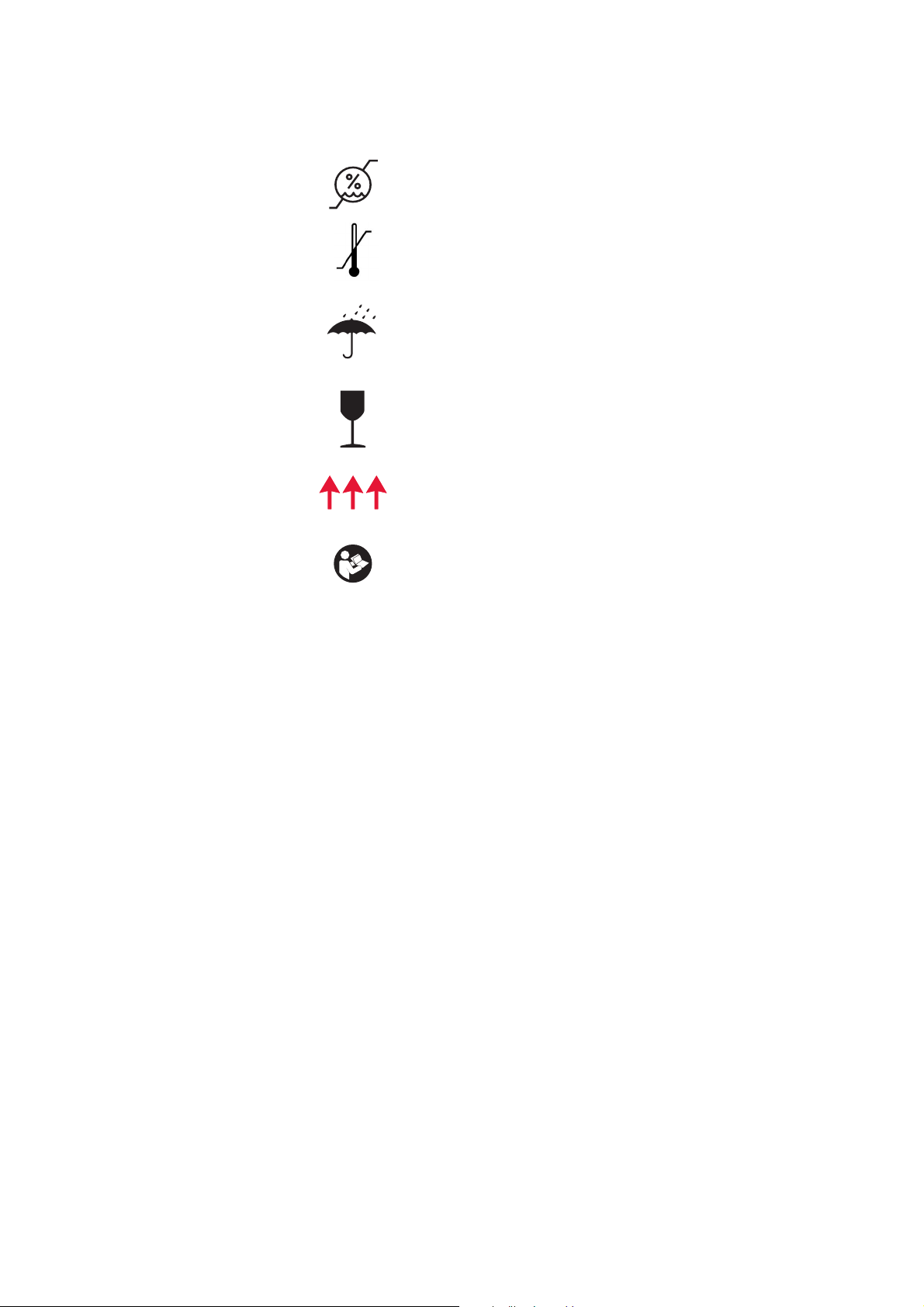
Storage conditions, humidity level
Storage conditions, temperature level
Storage conditions, keep dry
Fragile, handle with care
This end up
Read the instruction manual
P/N 120745-IE, Manual revision: AA Haemonetics
®
Cell Saver® Elite® User Manual
Page 19

Chapter 1, Introduction 19
Device Specifications
Note: The use of materials not provided or recommended by Haemonetics is
the sole responsibility of the end-user, and the end-user will be responsible for
any personal injury and/or property damage related to such use.
Device Classification
Physical Specifications
The Cell Saver Elite is classified as a continuous operation, Class I, Type CF,
IPX1 device, as defined by IEC/EN 60601 standards for medical electrical
equipment.
The approximate dimensions and weight of the Cell Saver Elite device are as
follows:
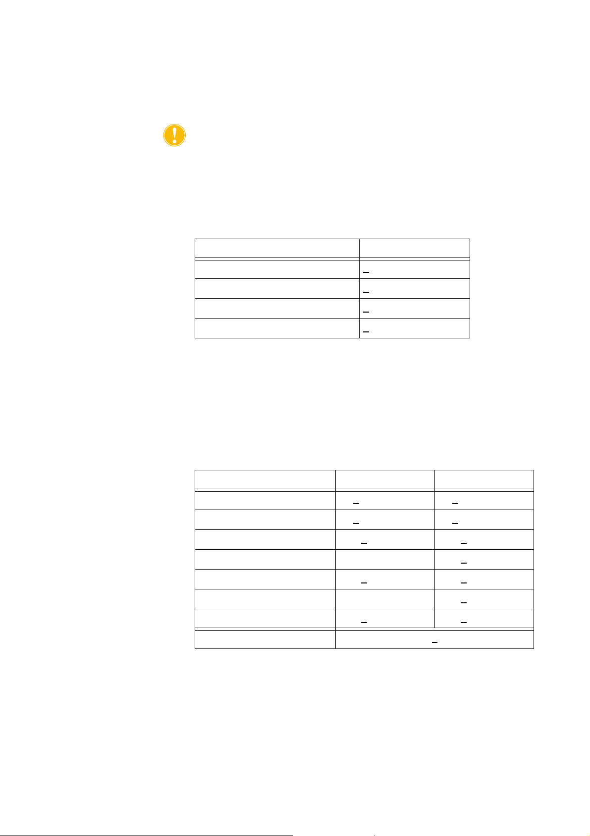
Table 3, Physical Specifications
Depth/cm (in.) Height/cm (in.) Width/cm (in.)
Device Alone 54.6 cm
(21.5 in)
Device With Cart
IV poles extended 67.3 cm
(26.5 in)
IV poles down 67.3 cm
(26.5 in)
Weight of device 25 kg (56 lbs)
Weight of cart 18 kg (39 lbs)
41.9 cm
(16.5 in)
182.9 cm
(72 in)
121.9 cm
(48 in)
29.8 cm
(11.75 in)
53.3 cm
(21 in)
53.3 cm
(21 in)
Environmental Specifications
Haemonetics
®
Cell Saver® Elite® User Manual P/N 120745-IE, Manual revision: AA
The noise level of the Cell Saver Elite device is < 70 dB.
The following environmental conditions should be respected pertaining to
operation and storage of the Cell Saver Elite device.
Warning: Equipment not suitable for use in the presence of a flammable
anesthetic mixture with air or with oxygen or nitrous oxide.
Page 20

20 Chapter 1, Introduction
Note: Store disposables in a dry place away from solvent va pors and extremes
of temperature.
Table 4, Environmental Specifications
Conditions Values
Electrical Specifications
Ambient operating
temperature
Storage/transportation
temperature
Operating humidity level 8 to 80% R.H., non-condensing above 0
Atmospheric pressure range <
The electrical specifications for operating the Cell Saver Elite device are as
follows
Caution: The Cell Saver Elite device must be operated in an environment
compatible to the requirements of the IEC/EN 60601-1-2:2001 Standard,
Electromagnetic compatibility (EMC).
Additional IEC/EN compliance information is available in Chapter 12.
Note: The power source used must be properly grounded.
Table 5, Electrical Input Power
Rated Voltage Rated Current Fuse Frequency
10 °C to 27 °C (50 °F to 80.6 °F)
-20 °C to 50 °C (-4 °F to 122 °F)
°C
2438 meters (8000 ft.)
100–120 V 3.0 A T3.15A250V 50/60 Hz
200–240 V 1.5 A T3.15A250V 50/60 Hz
Table 6, Enclosure/Chassis Leakage Current Spec i fi ca ti o ns *
Condition Polarity Ground Max Value
Normal Normal 100 µΑ
Normal
Reverse Normal 100 µΑ
Reverse Open 500 µΑ
Single fault
Normal Open 500 µΑ
*In accordance with IEC/EN 60601-1 standard, medical electrical equipment,
general requirements for safety.
P/N 120745-IE, Manual revision: AA Haemonetics
®
Cell Saver® Elite® User Manual
Page 21

Chapter 1, Introduction 21
Suction Specifications
The specifications for the Cell Saver Elite suction are as follows.
Table 7, Suction Specifications
Characteristics Values
SmartSuction
Recommended reservoir volume ≤ 3 L
Recommended A&A line length ≤ 12 ft [3.6 m]
Recommended A&A line inner
diameter
Recommended suction tip inner
diameter
Operating vacuum 20 to 150 mmHg
Vacuum cutoff 175 mmHg
Maximum free air flow 40 L/min
Manual Suction
Operating vacuum 50 to 250 mmHg
0.3 in [7.6 mm]
0.3 in [7.6 mm]
(2.7 to 20.0 kPa; 26.7 to 200 mbar)
(23.3 kPa; 233 mbar)
(6.7 to 33.3 kPa; 66.7 to 333.3
mbar)
Laser Specifications
Maximum free air flow 40 L/min
Post-Op Suction
Operating vacuum 25 to100 mmHg
(3.3 to 13.3 kPa; 33.3 to 133.3
mbar)
Maximum free air flow 40 L/min
The Cell Saver Elite device is a class 3R laser product.
The laser specifications for the Cell Saver Elite device are as follows:
Table 8, Laser Specifications
Characteristics Values
Max radiation output 3 mW
Wavelength 650 nm
Max light output 7 mW (bowl optics)
1.7 mW +/- 0.2 mW (barcode reader)
Standards IEC/EN 60825-1:2007
a
Haemonetics
®
Cell Saver® Elite® User Manual P/N 120745-IE, Manual revision: AA
Page 22

22 Chapter 1, Introduction
a. The Cell Saver Elite device complies with IEC/EN 60825-1:2007 standard,
safety of laser products, equipment classification and requirements.
The following labels may appear on the device:
P/N 120745-IE, Manual revision: AA Haemonetics
®
Cell Saver® Elite® User Manual
Page 23

Chapter 1, Introduction 23
Ordering Information
Refer to the table below for ordering information regarding disposables.
Table 9, Disposables Ordering Information
Item Description List Number Quantity
Per Case
Waste bag, 10 L CSE-B-1000 10
Cell Saver Elite processing set (70 mL) CSE-P-70 8
Cell Saver Elite processing set (125 mL) CSE-P-125 8
Cell Saver Elite processing set (225 mL) CSE-P-225 8
Sequestration set CSE-SQ-1000 8
SmartSuction filtered vacuum line, non-sterile HAR-A-1000 10
SmartSuction aspiration & anticoagulation line HAR-A-1003 10
Cell Saver collection reservoir, 3 L, 150 μ
raised filter
Cell Saver aspiration & anticoagulation line 00208-00 20
Aspiration & anticoagulant line for use with
softshell reservoirs
Cell Saver collection reservoir, 3L, 20 μ filter 00220-00 4
Reservoir, 40u, softshell 00240-MTSA 6
Cell Saver RBC bag, 1000 mL 00245-00 40
Reservoir, 170u, softshell 00300-MTSA 6
Postoperative drainage wash system - big bore 01500-BB 10
Postoperative drainage wash system 01500-FR 10
Postoperative drainage wash system - luer lock 01500-LL 10
Postoperative drainage wash system - spike 01500-SP 10
Refer to the table below for a list of user-replaceable parts.
Table 10, User-Replaceable Parts
Item Description Part Number
00205-00 4
00208-MT 18
Haemonetics
Reusable reservoir holder for use with softshell
reservoirs
Cardiotomy bracket 02116-00
Biohazard drain bag 35643-00
®
Cell Saver® Elite® User Manual P/N 120745-IE, Manual revision: AA
02100-MT
Page 24

24 Chapter 1, Introduction
Table 10, User-Replaceable Parts
Item Description Part Number
Wheel, 10 cm, locking, antistatic 49762-02
Wheel, 10 cm, locking 49762-03
Air exhaust filter cover 100875-00
Air exhaust filter 100878-00
Knob for touch screen mount and reservoir weigher 102924-00
Air intake filter 103003-00
Large cart bin 107090-00
Small cart bin 107094-00
2-hook saline bag hangers 107098-00
IV pole with 4-hook top 107099-00
70 mL centrifuge chuck adaptor 107581-00
Power cord, UK, 4.9m, 5A, 250VAC 109183-00
Power cord, European, 4.9m, 10A, 250VAC 109184-00
Printer kit 114282-00
User manual, IE 120747-IE
P/N 120745-IE, Manual revision: AA Haemonetics
®
Cell Saver® Elite® User Manual
Page 25

Chapter 2
Equipment Description
Overview . . . . . . . . . . . . . . . . . . . . . . . . . . . . . . . . . . . . . . . . . . . . . . . . . . . 27
Top Deck and Front Panel Components . . . . . . . . . . . . . . . . . . . . . . . . . . . 28
Device Cover . . . . . . . . . . . . . . . . . . . . . . . . . . . . . . . . . . . . . . . . . . . . . 28
Effluent Line Sensor . . . . . . . . . . . . . . . . . . . . . . . . . . . . . . . . . . . . . . . . 28
Air Detector . . . . . . . . . . . . . . . . . . . . . . . . . . . . . . . . . . . . . . . . . . . . . . . 28
Pump. . . . . . . . . . . . . . . . . . . . . . . . . . . . . . . . . . . . . . . . . . . . . . . . . . . . 28
Handle. . . . . . . . . . . . . . . . . . . . . . . . . . . . . . . . . . . . . . . . . . . . . . . . . . . 28
Valve Module. . . . . . . . . . . . . . . . . . . . . . . . . . . . . . . . . . . . . . . . . . . . . . 29
Centrifuge System . . . . . . . . . . . . . . . . . . . . . . . . . . . . . . . . . . . . . . . . . 30
Rear and Side Panel Components. . . . . . . . . . . . . . . . . . . . . . . . . . . . . . . . 32
Waste Bag Weigher . . . . . . . . . . . . . . . . . . . . . . . . . . . . . . . . . . . . . . . . 32
Air Intake. . . . . . . . . . . . . . . . . . . . . . . . . . . . . . . . . . . . . . . . . . . . . . . . . 32
Air Exhaust Filter. . . . . . . . . . . . . . . . . . . . . . . . . . . . . . . . . . . . . . . . . . . 32
Touch Screen Storage Mount . . . . . . . . . . . . . . . . . . . . . . . . . . . . . . . . . 32
Vacuum Connection . . . . . . . . . . . . . . . . . . . . . . . . . . . . . . . . . . . . . . . . 32
Touch Screen Cable Entry . . . . . . . . . . . . . . . . . . . . . . . . . . . . . . . . . . . 33
Equipotential Ground Terminal Connection. . . . . . . . . . . . . . . . . . . . . . . 33
Reservoir Weigher Connection . . . . . . . . . . . . . . . . . . . . . . . . . . . . . . . . 33
Power Entry Module . . . . . . . . . . . . . . . . . . . . . . . . . . . . . . . . . . . . . . . . 33
Power Cord . . . . . . . . . . . . . . . . . . . . . . . . . . . . . . . . . . . . . . . . . . . . . . . 33
Touch Screen Display . . . . . . . . . . . . . . . . . . . . . . . . . . . . . . . . . . . . . . . . . 34
Status Beacon. . . . . . . . . . . . . . . . . . . . . . . . . . . . . . . . . . . . . . . . . . . . . 34
Barcode Reader . . . . . . . . . . . . . . . . . . . . . . . . . . . . . . . . . . . . . . . . . . . 34
Stop Key . . . . . . . . . . . . . . . . . . . . . . . . . . . . . . . . . . . . . . . . . . . . . . . . . 35
Touch Screen Mount . . . . . . . . . . . . . . . . . . . . . . . . . . . . . . . . . . . . . . . . 35
USB Connection . . . . . . . . . . . . . . . . . . . . . . . . . . . . . . . . . . . . . . . . . . . 35
Graphical User Interface . . . . . . . . . . . . . . . . . . . . . . . . . . . . . . . . . . . . . 35
Device Settings . . . . . . . . . . . . . . . . . . . . . . . . . . . . . . . . . . . . . . . . . . . . . . 46
Cart Components . . . . . . . . . . . . . . . . . . . . . . . . . . . . . . . . . . . . . . . . . . . . . 48
IV Poles. . . . . . . . . . . . . . . . . . . . . . . . . . . . . . . . . . . . . . . . . . . . . . . . . . 48
Device Mount . . . . . . . . . . . . . . . . . . . . . . . . . . . . . . . . . . . . . . . . . . . . . 48
Wheels . . . . . . . . . . . . . . . . . . . . . . . . . . . . . . . . . . . . . . . . . . . . . . . . . . 49
Reservoir weigher . . . . . . . . . . . . . . . . . . . . . . . . . . . . . . . . . . . . . . . . . . 49
Saline Hangers . . . . . . . . . . . . . . . . . . . . . . . . . . . . . . . . . . . . . . . . . . . . 49
Handle. . . . . . . . . . . . . . . . . . . . . . . . . . . . . . . . . . . . . . . . . . . . . . . . . . . 49
Processing Set Tub Holder . . . . . . . . . . . . . . . . . . . . . . . . . . . . . . . . . . . 49
Step Plate . . . . . . . . . . . . . . . . . . . . . . . . . . . . . . . . . . . . . . . . . . . . . . . . 49
Haemonetics® Cell Saver® Elite® User Manual P/N 120745-IE, Manual revision: AA
Page 26

26 Chapter 2, Equipment Description
Removable Bins . . . . . . . . . . . . . . . . . . . . . . . . . . . . . . . . . . . . . . . . . . . 49
P/N 120745-IE, Manual revision: AA Haemonetics
®
Cell Saver® Elite® User Manual
Page 27

Chapter 2, Equipment Description 27
1.
2.
9.
10.
5.
4.
11.
7.
3.
6.
8.
1. Device cover
2. Touch screen display
3. Effluent line sensor
4. Air detector
5. Pump cover and rotor
6. Pump platen
7. Handle
8. Reservoir weigher
9. Centrifuge system
10. Valve module
11. Ca rt
Overview
This chapter identifies the major components of the Cell Saver Elite system
and explains their intended functions. The components are located in the
following positions on the device:
Top deck
Front panel
Side panel
Rear panel
Touch screen
Cart
Note: Any references made to “left”, “right”, “top”, or “rear” are from the
perspective of a user facing the Cell Saver Elite device during a procedure.
Haemonetics
Figure 1, Cell Saver Elite system components
Refer to Chapter 3 for descriptions of the disposable set components.
®
Cell Saver® Elite® User Manual P/N 120745-IE, Manual revision: AA
Page 28

28 Chapter 2, Equipment Description
Top Deck and Front Panel Components
Device Cover The clear plastic cover protects the top deck components and disposable set
while allowing the user to visually monitor both the flow of blood through the
tubing, and the action of the pump and centrifuge.
The cover can be freely raised and lowered during setup and locks into place
while the centrifuge and pump are rotating. The centrifuge and pump must
come to a complete stop before the cover can be opened.
Effluent Line Sensor
The effluent line sensor monitors the quality of the bowl effluent, adjusts the
pump speed, and advances the system to the next phase when appropriate. If
the effluent line sensor is disabled, a corresponding status icon appears on the
procedure diagram. (See “Status Icons” on page 43 for more information.)
Air Detector The ultrasonic air detector monitors the fluid flow in the pump tubing.
During the Fill phase, the air detector senses air when the reservoir is empty.
During the Concentrate (Conc) phase, the air detector senses when the RBC
bag is empty. During the Wash phase, the air detector senses air when the
saline bag is empty. If the air detector senses air during Wash and 90% or more
of the necessary wash volume has been used, the device advances to the next
phase.
The air detector is also used during the Empty and Return phases to determine
when the centrifuge bowl is empty. This minimizes air returned to the RBC bag.
Pump The three-roller, peristaltic pump moves fluids in and out of the centrifuge bowl.
At its maximum speed it is capable of a flow of 1000 mL/min. A pump platen
holds the tubing in place against the pump. The user can open and close the
platen using the lever located below the platen.
Handle There are two handles located on the front panel and the rear of the device.
The handles enable easy lifting of the device when it is not attached to the cart.
P/N 120745-IE, Manual revision: AA Haemonetics
®
Cell Saver® Elite® User Manual
Page 29

Chapter 2, Equipment Description 29
1.
3.
4.
5.
6.
2.
1. Valve module cover
2. Manifold pressure
sensor
3. Latch
4. Yellow line valve
5. Red line valve
6. Blue line valve
Valve Module The valve module contains a manifold pressure sensor and four channels that
hold the processing set tubing in place. Three of the channels contain a pinch
valve that controls the flow of fluids through the set during a procedure.
Figure 2, Valve module
Pinch Valves
The three pinch valves occlude the three color-coded lines of the harness. The
function of each valve is as follows:
Yellow line valve: opens the pathway to the wash solution.
Red line valve: opens the pathway to the blood source, usually a
reservoir or extracorporeal circuit.
Blue line valve: opens the pathway to the RBC bag.
Manifold Pressure Sensor
The manifold pressure sensor monitors pressure levels in the blue and red
lines during Empty and Return and in the yellow line during Wash. If the clamp
on the RBC bag, collection bag, reservoir, or yellow line is inadvertently closed,
or the saline bag empties and collapses, the manifold pressure sensor stops
the pump and the device displays a message.
Valve Module Cover
The cover of the valve module secures the tubing in the channels. Push the
cover down and rotate the cover latch to close the cover.
The valve module cover is open, and the valves in the module are up when
loading the disposable set. The cover stays locked for the duration of the
procedure and unlocks automatically when the procedure is complete or if an
event message requires the user to access the valve manifold.
Haemonetics
®
Cell Saver® Elite® User Manual P/N 120745-IE, Manual revision: AA
Page 30
30 Chapter 2, Equipment Description
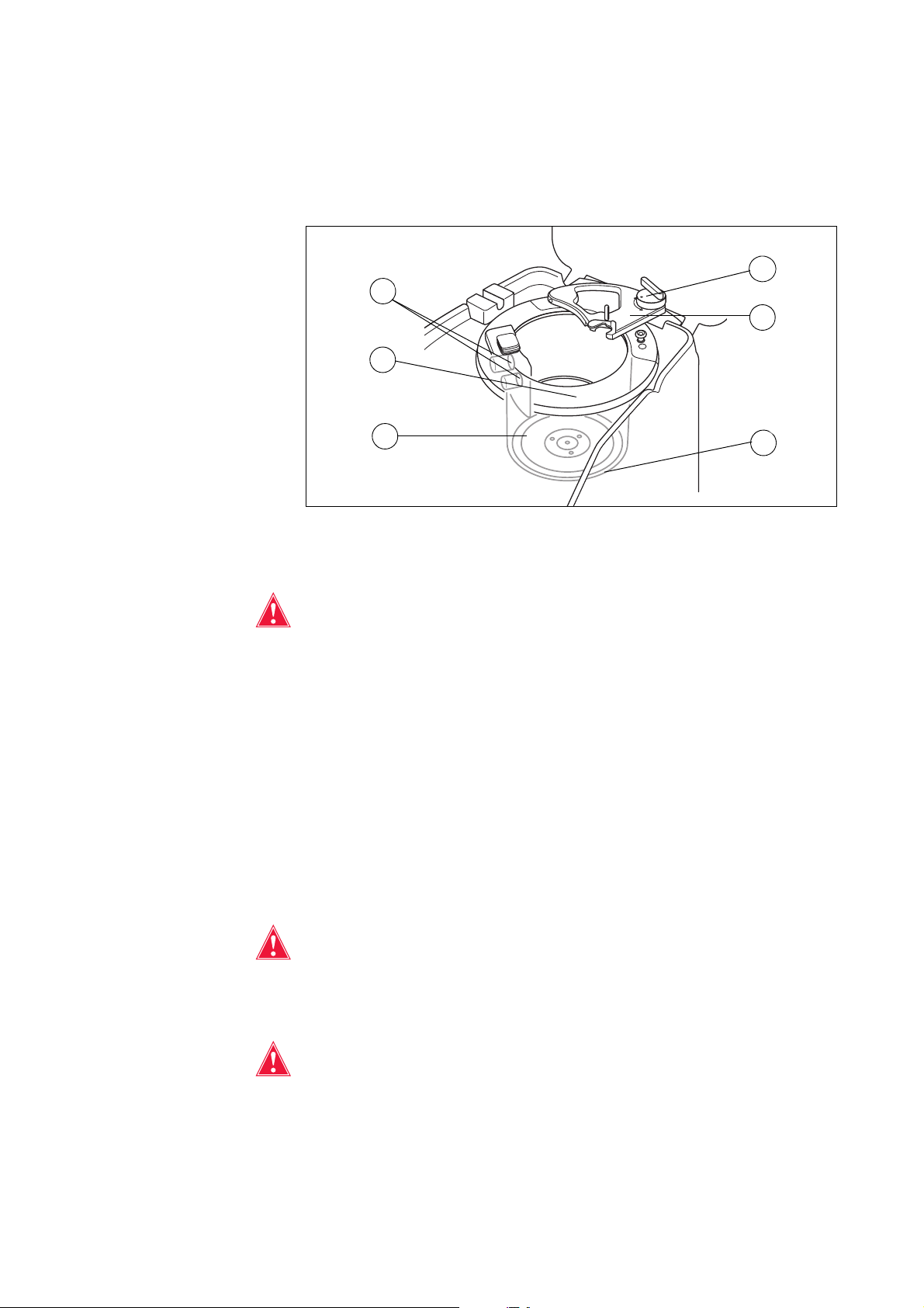
4.
1.
3.
5.
6.
2.
1. Bowl optics (laser
apertures)
2. Fluid detector (not
shown)
3. Centrifuge chuck
4. Header arm latch
5. Header arm
6. Centrifuge drain port
(under the centrifuge
chuck)
Centrifuge System
The centrifuge system holds the processing set bowl during device operation
and monitors the fluids inside the bowl.
Figure 3, Centrifuge components
Bowl Optics
Warning: The bowl optics emit laser radiation. Do not look directly into the
beam.
P/N 120745-IE, Manual revision: AA Haemonetics
The bowl optics sensors mounted in the centrifuge well monitor the fluid inside
the bowl and advance the device to the next phase when the RBCs reach a
predetermined level within the bowl.
Example: the device automatically advances from the Fill phase to the Wash
phase.
Fluid Detector
The fluid detector is an electronic fluid detection device mounted on the wall of
the centrifuge well. The fluid detector detects the presence of liquid in the event
of a bowl leak.
Centrifuge Chuck
Warning: The bowl base (or centrifuge chuck adaptor) must be firmly
installed and evenly seated in the centrifuge chuck. If the centrifuge chuck
spins with the bowl base (or adaptor) not evenly seated, as indicated by bowl
wobbling or noise, bowl damage will occur and the procedure must be
discontinued.
Warning: Do not grease any part of the centrifuge or centrifuge chuck
adaptor. If grease has been applied to the chuck, contact the Haemonetics
hotline immediately.
®
Cell Saver® Elite® User Manual
Page 31

Chapter 2, Equipment Description 31
The centrifuge chuck holds the rotating part of the bowl during a procedure. A
centrifuge drain port underneath the chuck allows blood to drain into a
biohazard waste bag in the event of a bowl leak.
Header Arm
The centrifuge header arm closes around the stationary part of the bowl during
a procedure. A latch secures the header arm in place.
Haemonetics
®
Cell Saver® Elite® User Manual P/N 120745-IE, Manual revision: AA
Page 32

32 Chapter 2, Equipment Description
A.
B.
C.
B.
4.
5.
6.
7.
8.
1.
2.
9.
10.
11.
C.
3.
A. Device Components
1. Waste bag weigher
2. Air intake (not shown –
bottom of device)
3. Air exhaust filter
(not shown – bottom of
device)
B. Cables and Connections
4. Touch screen storage
mount
5. Vacuum connection
6. Reservoir weigher
connection
7. Equipotential ground
terminal
8. Touch screen cable entry
C. Power Entry Module
(PEM)
9. Power cord connection
10. ON/OFF switch
11. Main fuse holder
Rear and Side Panel Components
Waste Bag Weigher
Air Intake The air intake allows air to circulate inside the device, keeping the internal
Air Exhaust Filter
Touch Screen Storage Mount
Vacuum Connection
P/N 120745-IE, Manual revision: AA Haemonetics
Figure 4, Rear and side panel components
The waste bag weigher monitors the amount of fluid collected in the waste bag.
When the weigher senses the waste bag is nearly full, the device displays a
message indicating the waste bag must be emptied or replaced.
components cool. The air intake contains a removable filter that can be cleaned
or replaced if necessary.
The air exhaust filter is a replaceable antibacterial filter, through which
externally vented exhaust from the SmartSuction
®
system passes.
The touch screen storage mount holds the touch screen in place during storage
and transport of the device.
The vacuum connection allows the user to connect the filtered vacuum line that
leads to the reservoir.
®
Cell Saver® Elite® User Manual
Page 33

Chapter 2, Equipment Description 33
Touch Screen Cable Entry
Equipotential
Ground
Terminal
The touch screen cable entry contains the cable that connects the device with
the touch screen.
The equipotential ground terminal connection allows the user to connect the
Cell Saver Elite device to other devices/equipment in the area, bringing them
to the same potential.
Connection
Reservoir
Weigher
The reservoir weigher connection contains the cable that connects the device
with the reservoir weigher.
Connection
Power Entry Module
The power entry module contains the power cord connection, ON/OFF switch,
and the main fuse holder.
Power Cord A power cord is supplied with the device. Inspect for a frayed or twisted power
cord. Do not replace the power cord with a substitute. If necessary, contact the
local Haemonetics representative for a replacement. Always ensure the power
cord is connected to an appropriately grounded power source.
Caution: Grounding reliability can only be achieved when the equipment is
connected to a properly grounded outlet.
Note: The power cord can be coiled around the cart handle during transport or
when the device is not connected to a power source.
Haemonetics
®
Cell Saver® Elite® User Manual P/N 120745-IE, Manual revision: AA
Page 34

34 Chapter 2, Equipment Description
2.
6.
4.
1.
3.
5.
1. Status beacon
2. Touch screen
3. Barcode reader (laser
aperture)
4. STOP key
5. Touch screen mount
6. USB connection
Touch Screen Display
The touch screen can be positioned at a comfortable height on the cart IV pole.
The user can easily rotate the display to the best viewing angle while the
display is secured to the pole.
The display screen can also be mounted on a separate IV pole that is 20-25
mm in diameter.
Status Beacon The status beacon indicates the general status of the procedure. The beacon
Barcode Reader
Figure 5, Parts of the device display
glows green when all operations are normal, yellow when user intervention is
needed, and red when the procedure is stopped.
There are corresponding color-coded alert bars on the status indicator (page
36) and the message area (page 41).
Warning: The class 3R barcode reader emits laser radiation. Do not look
directly into the beam.
The barcode reader scans barcode information, such as disposable set list
numbers, lot numbers and expiration dates, and operator and patient IDs, and
stores it in the memory of the device. It is located on the bottom of the device
display and is active when the Bowl Selection screen and Record or
Disposables tabs are displayed.
P/N 120745-IE, Manual revision: AA Haemonetics
®
Cell Saver® Elite® User Manual
Page 35

Chapter 2, Equipment Description 35
As a safety feature, the barcode reader emits a low-level laser until it detects a
barcode. It then turns on a full-power laser to scan the barcode. The reader
recognizes Codabar, Code 128, and ISBT 128 formats as valid barcode
formats.
Stop Key Pressing the (Stop) key immediately stops the pump and centrifuge. The
status indicator shows that the device is stopped. To restart the current phase,
ensure the device cover is closed; then touch (Play). To start a different
phase, touch the corresponding phase pad.
When the device is stopped in the Prime or Fill phase, double-pressing the
Stop key puts the device into Standby mode.
Touch Screen Mount
USB Connection
Graphical User Interface
The touch screen mount allows the user to move the touch screen horizontally
around the IV pole and adjust the angle of the screen.
The USB connection is used for software upgrades and allows users to
download procedure and technical data to a portable USB flash drive.
The graphical user interface (GUI) provides a simple and intuitive interface for
users to use during device operation and allows easy access to advanced
configuration options.
The Processing screen is the main procedure screen and is composed
primarily of touch pads that enable you to control the procedure. If a pad is
grayed out it means that particular function is not currently available.
Haemonetics
®
Cell Saver® Elite® User Manual P/N 120745-IE, Manual revision: AA
Page 36

36 Chapter 2, Equipment Description
1.
5.
6.
7.
11.
8.
9.
13.
15.
14.
16.
2. 4.3.
10. 12.
1. Status indicator
2. Suction pad
3. Play/Pause pad
4. Active Settings pad
5. Menu
6. Fill pad
7. Wash pad
8. Empty pad
9. Volume pad
10. Message area
11. Concentrate pad
12. Return pad
13. Pump control pads
14. Emergency Mode pad
15. Procedure diagram
16. Procedure statistics
1.
2.
1. Phase/mode
2. State
Figure 6, Parts of the Processing screen GUI
Status Indicator
The status indicator displays the current status of the device.
Figure 7, Example of the status indicator when the Fill phase is paused
This includes:
Phase/mode: The center area shows the current phase of the device.
Examples: Fill, Conc, Wash, Empty, Return, Standby.
State: The area on the bottom right of the status indicator shows the
current state of the device. Examples: stopped, paused.
P/N 120745-IE, Manual revision: AA Haemonetics
®
Cell Saver® Elite® User Manual
Page 37

Chapter 2, Equipment Description 37
Suction Pad
Figure 8, Example of the Suction pad
Warning: The recommended intraoperative suction setting is 200 mmHg (20
kPa; 200 mbar) or less. Maintain suction levels as low as possible to reduce
RBC damage as the shed blood travels through the suction tip to the
reservoir. Higher suction levels increase the amount of RBC hemolysis but
may be desired in the event of excessive blood loss when the need to clear
the field is greater than the need to prevent hemolysis.
The Suction pad allows you to choose between the following suction types:
SmartSuction: Autoregulates suction levels to optimize fluid removal.
The vacuum level is kept low when the device detects a high air-flow rate
at the suction tip, indicating surface skimming. The vacuum level
automatically increases when the device detects lower air-flow rates,
indicating submergence in fluid.
Note: Efficient operation of the SmartSuction
®
technology depends on the use
of a high air-flow disposable vacuum line and aspiration and anticoagulant
(A&A) line in conjunction with a reservoir that has a maximum capacity of 3
liters.
The Cell Saver Elite device has been calibrated to optimize SmartSuction
performance with the use of Haemonetics proprietary disposables and
recommended suction tips. Suction and fluid removal performa nce may
decline if incorrect or non-Haemonetics disposables are used with the system.
Manual: Allows you to manually set the suction level between 50 and
250 mmHg in 50 mmHg increments.
Post-Op: Provides a variable suction level with a default level of 75
mmHg. You may set the suction to 25 mmHg, 50 mmHg,
75 mmHg, 100 mmHg, or Off.
Post-op suction utilizes periodic suction relief. Suction runs at the
selected suction level for 10 minutes, turns off for 1 minute, and then
returns to the selected suction level for another 10 minutes. This cycle
repeats continuously throughout post-op operation.
Haemonetics
®
Cell Saver® Elite® User Manual P/N 120745-IE, Manual revision: AA
Page 38

38 Chapter 2, Equipment Description
Menu
Figure 9, Example of the Menu pad
The menu allows you to access the configurable settings, the Sequestration
protocol, and other options. The menu options include:
Cell Salvage
Sequestration (only available prior to starting the Cell Salvage protocol)
Settings
Records
System
Help
P/N 120745-IE, Manual revision: AA Haemonetics
®
Cell Saver® Elite® User Manual
Page 39

Chapter 2, Equipment Description 39
1. 2. 3.
1. Available pad (inactive
phase)
2. Active phase pad
3. Disabled pad
Phase Pads
Figure 10, Example of the phase pads
The phase pads include the Fill, Wash, Empty, Conc, and Return pads.
Phase pads change color based on their status:
Figure 11, Example of a phase pad in different states
Light blue background: The phase pad is available. You can touch the
pad to override the automatic progression of the device and manually
move the device into that phase.
Dark blue background: The device is already in the corresponding
phase. If the device is in a paused or stopped state, you can touch the
pad to resume the procedure.
Grayed: The pad is disabled.
Haemonetics
®
Cell Saver® Elite® User Manual P/N 120745-IE, Manual revision: AA
Page 40

40 Chapter 2, Equipment Description
1.
2.
1. Target wash volume
2. Wash volume used
2.
1.
3. 4.
1. Decrease
2. Increase
3. Cancel
4. Accept
During the Wash phase, the Wash pad expands to show the wash volume
used and the target wash volume.
Figure 12, Example of the Wash pad during the Wash phase
To change the target wash volume for the current cycle:
1. Touch Cycle Wash Volume. The Cycle Wash Volume box appears.
2. Use the +/- pads to increase or decrease the target wash volume for the
current wash cycle:
3. Touch (Accept) to save the change or (Cancel) to exit.
P/N 120745-IE, Manual revision: AA Haemonetics
Figure 13, Example of the Cycle Wash Volume box
®
Cell Saver® Elite® User Manual
Page 41

Chapter 2, Equipment Description 41
1.
4.
5.
3.
2.
1. Pause
2. Play
3. Current pump speed
4. Increase speed
5. Decrease speed
Message Area
Figure 14, Example of the message area
The message area at the bottom of the screen displays messages, prompts,
and information for the user. Messages are color-coded to show the alert state
of the device, and there is a corresponding status beacon on the top of the
display screen (See page 34). Green indicates normal; yellow indicates that
user intervention is needed; and red indicates that the procedure is stopped.
You can touch messages to expand them to view additional information. Then
touch the message bar to minimize them again. Yellow and red alerts
automatically appear in full-screen view.
Pump Control Pads
Haemonetics
Figure 15, Example of the pump control pads
The pump control pads control the motion and speed of the pump.The device
has default pump speeds that vary depending on bowl size, current phase, and
mode and are set to optimize performance. The pump speed parameters can
be adjusted during a procedure using the pump control pads.
To immediately stop the pumps, touch (Pause). To restart the current
phase, touch (Play), or to start a different phase, touch the corresponding
phase pad.
®
Cell Saver® Elite® User Manual P/N 120745-IE, Manual revision: AA
Page 42

42 Chapter 2, Equipment Description
4.
1.
6.
9.
7.
5.
8.
3.
2.
1. Waste bag icon
2. Bowl icon (225 mL)
3. Current cycle
4. Pump icon
5. Saline bag icon
6. Reservoir icon
7. Procedure statistics
8. Example of status icon
9. RBC bag icon
Procedure Diagram
The procedure diagram visually indicates the status and progress of the
procedure. It shows the movement of the pump, the movement of fluid through
the disposable set, if any error states occur during the procedure and the
procedure statistics.
Figure 16, Example of the procedure diagram
Procedure Statistics
The procedure statistics appear at the right of the procedure diagram and
indicate the volume of salvaged fluid processed, volume of saline used, and
volume of RBCs added to the RBC bag.
P/N 120745-IE, Manual revision: AA Haemonetics
®
Cell Saver® Elite® User Manual
Page 43

Chapter 2, Equipment Description 43
Status Icons
The procedure diagram displays status icons when there is an event message
or custom setting that affects the procedure.
Figure 17, Example of status icons
The following is a list of possible status icons and their meanings:
Almost Full: The device has detected approximately 7.5 liters of fluid in
the waste bag. The procedure will continue but the waste bag should be
emptied soon.
Auto-Fill Disabled: The reservoir weigher is not active. When in
Standby, you will need to touch Fill to enter the Fill phase.
Auto-Wash Ask User: When the device detects the bowl is full, it will
transition to the Fill Paused state, display a message indicating that the
bowl is full and ready to enter the Wash phase, and prompt you to select
the next action.
Auto-Wash Disabled: The device will remain in the Fill phase until you
touch Wash to transition from the Fill phase to the Wash phase.
Warning: You should monitor the effluent quality during the Wash phase
when the Effluent Sensor Disabled icon appears. The effluent line sensor is
not active and is therefore not monitoring effluent quality.
Effluent Sensor Disabled: This icon appears if there has been a line
sensor failure and you have chosen to continue the procedure while
monitoring the quality of the effluent.
Haemonetics
®
Cell Saver® Elite® User Manual P/N 120745-IE, Manual revision: AA
Page 44

44 Chapter 2, Equipment Description
Full: The device has detected approximately 8.5 liters of fluid in the
waste bag. It will not process additional fluid until the waste bag is
replaced or partially emptied.
Regulation Disabled: The pump speed is not being regulated. This icon
appears if the current settings group has pump regulation set to off or if
the pump speed has been manually adjusted from the default setting
and during Emergency mode.
Replace Wash Solution: The air detector has sensed air while in the
Wash phase. This icon typically indicates the wash solution needs to be
replaced.
Unwashed Cells: This icon appears if the device enters the Empty
phase without executing a Wash phase. The cells currently moving to
the RBC bag have not been washed.
Wash Skip: The device will transition from the Fill phase to the Empty
phase without washing the RBCs.
Emergency Mode Pad
Figure 18, Example of the Emergency Mode pad
The Emergency Mode pad allows the user to switch the device into
Emergency mode. During Emergency mode the device processes blood at
high speeds. Emergency mode is not available when using a 70mL bowl
disposable set. See “Emergency Mode” on page 87 for more information.
P/N 120745-IE, Manual revision: AA Haemonetics
®
Cell Saver® Elite® User Manual
Page 45

Chapter 2, Equipment Description 45
Active Settings Pad
Figure 19, Example of the Active Settings pad
The Active Settings pad displays the current settings group selection. To
change the active settings group, touch Active Settings and select a different
settings group from the drop-down list.
Volume Pad
Figure 20, Stages of the Volume pad
The Volume pad controls the audible signal that sounds for any notices,
warnings, or alerts. When a red alert occurs, an audible signal sounds
continuously. You can temporarily silence the signal for that alert by touching
the Volume pad. During normal operation when no alert is occurring, you can
use the Volume pad to adjust the event volume or touch Mute All to mute the
signal for all events.
Haemonetics
®
Cell Saver® Elite® User Manual P/N 120745-IE, Manual revision: AA
Page 46

46 Chapter 2, Equipment Description
Device Settings
The System screen provides access to the Cell Saver Elite device settings. To
access the System screen, touch (Menu) and select System from the
drop-down menu.
Figure 21, Example of the System screen
The device settings are password protected with three different levels of
access: basic user, administrator, and Haemonetics technician. To unlock the
System screen, touch Unlock, enter your password, and touch (Accept).
The device setting options include:
Basic User Access (Password: USER)
Surgery Presets: Edit the list of surgeons, surgery types, and
operators.
Clock: Change the date or time.
Administrator Access
Startup Mode: Determine which settings group the device defaults to
upon power-on.
Sounds: Change the device tones and volume.
Options: Change the language, region, date/time format, units of
measure, and show/hide select fields.
P/N 120745-IE, Manual revision: AA Haemonetics
®
Cell Saver® Elite® User Manual
Page 47

Chapter 2, Equipment Description 47
Export Settings: Export all settings to a USB flash drive.
Software Update: View available software versions.
Import Settings: Select settings to import from a USB flash drive.
Haemonetics Technician Access
Service: Access the manufacturing screens.
Haemonetics
®
Cell Saver® Elite® User Manual P/N 120745-IE, Manual revision: AA
Page 48

48 Chapter 2, Equipment Description
1.
6.
3.
7.
9.
5.
11.
8.
10.
2.
4.
1. IV poles
2. Backstop
3. Device mount
4. Mounting pins
5. Wheels
6. Saline hangers
7. Handle
8. Processing set tub
holder
9. Step plate
10. Antistatic wheel
11. Removable bins
Cart Components
The Cell Saver Elite cart has four wheels that ensure maneuverability. The unit
can be tipped back on the rear wheels to pass over power cords, door sills, and
other obstructions. The Cell Saver Elite device can be removed from the cart
to allow for easy transport in cars and vans.
IV Poles The left IV pole contains the mount for the touch screen, and the right IV pole
Device Mount The device mount is the flat plate that the device rests on. A backstop at the
P/N 120745-IE, Manual revision: AA Haemonetics
Figure 22, Cart components
contains the reservoir weigher. Both poles can be easily lowered and locked in
the down position for ease of transport.
rear of the mount supports the back of the device and two locking pins near the
front of the mount lock the device into place.
®
Cell Saver® Elite® User Manual
Page 49

Chapter 2, Equipment Description 49
Wheels The wheels can be locked to secure the cart in position. The right rear wheel
provides antistatic protection.
Reservoir weigher
The reservoir weigher holds the collection reservoir, tracks the amount of fluid
in the reservoir, and communicates this information to the device. The reservoir
weigher contains a tubing support that supports the tubing exiting the top of the
reservoir.
For the first cycle, the device uses the preset value from calibration as a zero
value. In subsequent cycles, it continues to use this value until it detects air
during Fill. At that point, the system will tare the reservoir weigher, and the
current weight of the reservoir and contents will be considered zero. As a
result, any residual substances trapped in the filter when an air detect occurs
will not count towards the volume of the reservoir.
Note: The reservoir weigher ships with the Cell Saver Elite device but gets
mounted on the cart as shown in Figure 1 on page 27.
Saline Hangers The saline hangers hold the saline bags during the procedure.
Handle The handle at the back should be used when moving the cart and enables you
to easily maneuver it around and over obstacles.
Processing Set Tub Holder
The processing set tub holder extends to provide support for the processing set
tub during processing set installation.
Step Plate The step plate enables the user to tilt the cart backwards slightly to pass over
thresholds or small obstacles. Place one foot on the step plate and press down
to tilt the cart backwards. Always hold onto the cart handle while tilting the cart
to maintain stability.
Removable Bins
Haemonetics
®
Cell Saver® Elite® User Manual P/N 120745-IE, Manual revision: AA
The removable storage bins provide convenient storage space for any items
related to the device or procedure.
Page 50

Page 51

Chapter 3
Disposable Set Description
Overview . . . . . . . . . . . . . . . . . . . . . . . . . . . . . . . . . . . . . . . . . . . . . . . . . . . 52
Reservoir . . . . . . . . . . . . . . . . . . . . . . . . . . . . . . . . . . . . . . . . . . . . . . . . . . . 53
The A&A Line & Post-Op Set . . . . . . . . . . . . . . . . . . . . . . . . . . . . . . . . . . . . 54
A&A Line . . . . . . . . . . . . . . . . . . . . . . . . . . . . . . . . . . . . . . . . . . . . . . . . . 54
Post-Op Set . . . . . . . . . . . . . . . . . . . . . . . . . . . . . . . . . . . . . . . . . . . . . . 54
Vacuum Line . . . . . . . . . . . . . . . . . . . . . . . . . . . . . . . . . . . . . . . . . . . . . . . . 55
Processing Set Elements . . . . . . . . . . . . . . . . . . . . . . . . . . . . . . . . . . . . . . . 56
Tubing Harness. . . . . . . . . . . . . . . . . . . . . . . . . . . . . . . . . . . . . . . . . . . . 56
Bags . . . . . . . . . . . . . . . . . . . . . . . . . . . . . . . . . . . . . . . . . . . . . . . . . . . . 57
Centrifuge Bowl. . . . . . . . . . . . . . . . . . . . . . . . . . . . . . . . . . . . . . . . . . . . 57
Sequestration Set. . . . . . . . . . . . . . . . . . . . . . . . . . . . . . . . . . . . . . . . . . . . . 59
Haemonetics® Cell Saver® Elite® User Manual P/N 120745-IE, Manual revision: AA
Page 52

52 Chapter 3, Disposable Set Description
Overview
The Cell Saver Elite device utilizes single-use disposable sets to collect blood
salvaged during a procedure. Each disposable set is individually packaged in
a sealed plastic tub or wrapping.
The following disposable sets are available:
Reservoir
Aspiration and anticoagulant (A&A) line
Vacuum line
Processing set
Post-op set
Sequestration set
This chapter describes typical disposable set elements.
P/N 120745-IE, Manual revision: AA Haemonetics
®
Cell Saver® Elite® User Manual
Page 53

Chapter 3, Disposable Set Description 53
1.
2.
3.
4.
1. Filtered inlet ports (x3)
2. Reservoir
3. Reservoir drain port
4. Vacuum line connection
Reservoir
Reservoir
The collection reservoir holds the unprocessed salvaged blood from the field.
The top of the reservoir contains a vacuum connection and three filtered inlet
ports for A&A line and post-op suction set connections. The reservoir also has
a drain port on the bottom and an internal filter. It connects to the processing
set via the reservoir drain port.
Figure 23, Example of a reservoir
Note: Softshell reservoirs (LN 00300-MTSA and LN 00240-MTSA) must be
used with the LN 00208-MT A&A line and the reusable reservoir holder 02100MT.
Haemonetics
®
Cell Saver® Elite® User Manual P/N 120745-IE, Manual revision: AA
Page 54

54 Chapter 3, Disposable Set Description
1.
2.
3.
4.
1. Drip chamber
2. Roller clamp
3. Reservoir connection
4. Suction tip connection
1.
2. 3.
6.
4. 5.
1. Reservoir connection
2. Connection spike
3. Post-op line
4. “Metec” reservoir
adaptor
5. Anticoagulant port
6. Wound drain connectors
The A&A Line & Post-Op Set
A&A Line The A&A line is used to collect blood intraoperatively from the surgical field.
The packaging allows it to be delivered into the sterile field.
Figure 24, Example of an A&A line
Note: Efficient operation of the SmartSuction
®
technology depends on the use
of a high air-flow disposable vacuum line and aspiration and anticoagulant
(A&A) line in conjunction with a reservoir that has a maximum capacity of 3
liters.
The Cell Saver Elite device has been calibrated to optimize SmartSuction
performance with the use of Haemonetics proprietary disposables and
recommended suction tips. Suction and fluid removal performa nce may
decline if incorrect or non-Haemonetics disposables are used with the system.
Post-Op Set The post-op set is used to collect blood postoperatively from wound drain
tubing placed into the wound while the patient is in the operating room.
P/N 120745-IE, Manual revision: AA Haemonetics
Figure 25, Example of a post-op set
®
Cell Saver® Elite® User Manual
Page 55

Chapter 3, Disposable Set Description 55
1.
2.
3.
1. Hydrophobic filter
2. Reservoir vacuum port
connection
3. Device vacuum port
connection
Vacuum Line
Caution: Use of an incorrect or non-Haemonetics vacuum line may affect
suction performance and damage the device.
The single-use, filtered vacuum line connects the vacuum port on the rear
panel of the device to the vacuum port of the reservoir. The vacuum line
contains an in-line hydrophobic filter that provides overflow protection to the
device.
Figure 26, Example of a filtered vacuum line
Haemonetics
®
Cell Saver® Elite® User Manual P/N 120745-IE, Manual revision: AA
Page 56

56 Chapter 3, Disposable Set Description
5.
7.
6.
4.
11.
10.
9.
8.
1.
2.
3.
1. Blue line
2. Red line
3. Yellow line
4. Centrifuge bowl
5. Tubing manifold
6. Ratchet clamp
7. Cap
8. RBC bag
9. Collection reservoir
connector
10. Saline bag spikes
11. Waste bag
Processing Set Elements
The processing set is the disposable set in which blood is collected, washed
and separated into RBCs and waste. The processing set includes the following
parts:
Tubing harness: the color-coded lines and the plastic tubing manifold.
Bags: the RBC bag and waste bag.
Bowls: the centrifuge bowl (70 mL, 125 mL, or 225 mL)
Tubing Harness The processing set tubing harness contains four lines and a tubing manifold:
P/N 120745-IE, Manual revision: AA Haemonetics
Figure 27, Example of processing set components
The red line connects to the unprocessed blood source.
The yellow line connects to the saline solution.
The blue line attaches to the RBC bag.
The tubing manifold holds the tubing in place in the pump module and
holds the clear tubing going to the centrifuge.
All three color-coded lines pass through the pinch valves in the valve module.
The three colored lines combine into a single clear line as they leave the valve
module and enter the pump module.
The clear line passes through the pump, air detector, and valve module and
enters the centrifuge well. Inside the well, the line connects to the inlet port of
the bowl.
®
Cell Saver® Elite® User Manual
Page 57

Chapter 3, Disposable Set Description 57
The effluent line, connected to the outlet port of the bowl, exits the centrifuge
well through the effluent line sensor and connects to the waste bag.
Bags The processing set contains the following two receptacles:
The waste bag
The RBC bag
Waste Bag
The 10 L waste bag holds the waste solution, including plasma, cellular
components, and saline solution washed out of the red cells during processing.
It contains a drain port at the bottom, for emptying the waste bag, and a vent
with an antibacterial filter at the top of the bag, used to aid in venting the bag
during the sterilization process.
Note: When emptying
fall below the 1 liter mark. This ensures that sufficient air is retained in the
system to empty the bowl.
Note: When replacing
is not empty, return its contents to the reservoir, replace the waste bag, and
process again.
RBC Bag
The 1L RBC bag holds the processed red cells for reinfusion to the patient.
Centrifuge Bowl Centrifuge Bowl
The key component of the processing set is the centrifuge bowl. Inside the bowl
the collected RBCs are separated, washed, and packed.
The bowl consists of two subassemblies: an inner assembly that remains
stationary and an outer assembly that rotates. The rotating outer assembly
contains the centrifugation chamber where the blood is processed. The
stationary inner assembly contains the inlet and outlet ports.
The two subassemblies of the bowl are joined with a rotary seal which forms a
barrier between the inside and outside of the bowl. The effectiveness of the
seal may be impaired if the bowl is incorrectly seated in the chuck. Fully seating
the bowl in the centrifuge chuck will ensure proper function.
the waste bag, do not allow the fluid level in the bag to
the waste bag, make sure the bowl is empty. If the bowl
Haemonetics
®
Cell Saver® Elite® User Manual P/N 120745-IE, Manual revision: AA
Page 58

58 Chapter 3, Disposable Set Description
1. Inlet
2. Outlet
3. Rotating outer subassembly
4. Stationary inner
subassembly
1.
2.
3.
4.
1.
2.
3.
1. 70mL bowl
2. 125mL bowl
3. 225mL bowl
Figure 28, Example of the Latham bowl subassemblies
There are three bowl sizes: 70mL, 125mL, and 225mL. The 125mL and 225mL
bowls are Latham bowls. The 70mL bowl is uniquely shaped to efficiently
separate smaller volumes of fluid.
Figure 29, Example of the three bowl sizes
Centrifuge Chuck Adaptor
Warning: Do not grease any part of the centrifuge or centrifuge chuck
adaptor. If grease has been applied to the chuck, contact the Haemonetics
hotline immediately.
The 70mL bowl requires a centrifuge chuck adaptor to correctly load the bowl.
The chuck adaptor is a white plastic cylinder that snaps into the centrifuge
chuck. Install the chuck adaptor before loading the processing set.
P/N 120745-IE, Manual revision: AA Haemonetics
®
Cell Saver® Elite® User Manual
Page 59

Chapter 3, Disposable Set Description 59
1.
8.
10.
5.
4.
6.
7.
9.
10.
9.
3.
2.
1. Blood bag line ratchet
clamps
2. Blood bag spikes
3. Twist-lock connector
4. Red line connection
5. Reservoir drain port
connection
6. Effluent line connection
7. Yellow, blue, and clear
line ratchet clamps
8. Air bag
9. Collection bag ratchet
clamps
10. Collection bags
Sequestration Set
The Sequestration set allows the sequestration of platelets before the
beginning of a Cell Salvage procedure. The parts of the Sequestration set
include the:
Blood bag adaptor harness: the tubing that connects the blood bags
to the red line of the processing set. At the end of Sequestration, the user
removes the upper portion of the blood bag adaptor harness using the
twist-lock connector.
Collection bag harness: the collection bags and air bag
Haemonetics
Figure 30, Example of a Sequestration set
®
Cell Saver® Elite® User Manual P/N 120745-IE, Manual revision: AA
Page 60

Page 61

Chapter 4
Safety and Patient Care Precautions
Storing and Handling the Device and Disposables . . . . . . . . . . . . . . . . . . . 62
Storing and Handling the Device . . . . . . . . . . . . . . . . . . . . . . . . . . . . . . 62
Storing and Handling the Disposables . . . . . . . . . . . . . . . . . . . . . . . . . . 62
Inspecting the Components . . . . . . . . . . . . . . . . . . . . . . . . . . . . . . . . . . 62
Transporting the Device . . . . . . . . . . . . . . . . . . . . . . . . . . . . . . . . . . . . . 63
Warnings for the User . . . . . . . . . . . . . . . . . . . . . . . . . . . . . . . . . . . . . . . . . 65
Electrical Shock Hazards . . . . . . . . . . . . . . . . . . . . . . . . . . . . . . . . . . . . 65
Leakage Current Control. . . . . . . . . . . . . . . . . . . . . . . . . . . . . . . . . . . . . 65
Power Outlet Connection . . . . . . . . . . . . . . . . . . . . . . . . . . . . . . . . . . . . 65
Laser Radiation Hazards . . . . . . . . . . . . . . . . . . . . . . . . . . . . . . . . . . . . 65
Mechanical Hazards/Rotating Parts . . . . . . . . . . . . . . . . . . . . . . . . . . . . 65
Communicable Disease Precautions . . . . . . . . . . . . . . . . . . . . . . . . . . . 66
Preventing Problems During a Procedure . . . . . . . . . . . . . . . . . . . . . . . . . . 67
Understanding the Risk of Hemolysis . . . . . . . . . . . . . . . . . . . . . . . . . . . 67
Avoiding Flow Restrictions . . . . . . . . . . . . . . . . . . . . . . . . . . . . . . . . . . . 67
Avoiding Overheating . . . . . . . . . . . . . . . . . . . . . . . . . . . . . . . . . . . . . . . 68
Avoiding Continuous Aspiration . . . . . . . . . . . . . . . . . . . . . . . . . . . . . . . 68
Avoiding Red Blood Cell Spillage . . . . . . . . . . . . . . . . . . . . . . . . . . . . . . 68
Managing the Inventory of Air . . . . . . . . . . . . . . . . . . . . . . . . . . . . . . . . . 70
Patient Care Precautions . . . . . . . . . . . . . . . . . . . . . . . . . . . . . . . . . . . . . . . 71
Reinfusing Blood. . . . . . . . . . . . . . . . . . . . . . . . . . . . . . . . . . . . . . . . . . . 71
Replacing Depleted Clotting Factors . . . . . . . . . . . . . . . . . . . . . . . . . . . 71
Contraindications for Use . . . . . . . . . . . . . . . . . . . . . . . . . . . . . . . . . . . . 72
Using Anticoagulants . . . . . . . . . . . . . . . . . . . . . . . . . . . . . . . . . . . . . . . 72
Factors Affecting Processing Time. . . . . . . . . . . . . . . . . . . . . . . . . . . . . . . . 73
Cell Salvage . . . . . . . . . . . . . . . . . . . . . . . . . . . . . . . . . . . . . . . . . . . . . . 73
Sequestration . . . . . . . . . . . . . . . . . . . . . . . . . . . . . . . . . . . . . . . . . . . . . 73
Haemonetics® Cell Saver® Elite® User Manual P/N 120745-IE, Manual revision: AA
Page 62

62 Chapter 4, Safety and Patient Care Precautions
Storing and Handling the Device and Disposables
Safe and successful operation depends in part on the proper routine handling
of the Cell Saver Elite device and disposables. The operator should be aware
of the problems that could result if the device or disposable material is stored,
installed or used incorrectly.
Storing and Handling the Device
Storing and Handling the Disposables
Warning: If the Cell Saver Elite device is stored at a temperature outside the
operating temperature range, allow sufficient time for the device to
equilibrate to room temperature before use.
Do not operate or store the Elite device in an area where flammable gases or
vapors are present. The user should always handle the device with clean, dry
hands or gloves.
Minimize the length of storage for disposables by using sets with an earlier
expiration date before using those with a later expiration date. This is referred
to as the first-in, first-out (FIFO) technique.
All disposable material should be stored in a dry, well-ventilated area free from
exposure to chemical vapors. Many plastic materials are sensitive to chemicals
such as solvents, refrigerants and detergents. The mechanical properties of
plastic material may be seriously degraded when exposed to solvent vapors.
Avoid direct contact of the disposable plastic materials with all halogenated
hydrocarbon-based anesthetic agents, e.g., Isoflurane (Forane), Enflurane
(Efrane or Ethrane), Halothane (Fluothane or Rhodialothan); these agents
attack plastics.
The user should always handle the disposable set components with clean, dry
hands or gloves to avoid contaminating the surface of disposable plastic
components with chemicals.
Inspecting the Components
P/N 120745-IE, Manual revision: AA Haemonetics
Prior to installation, the user should inspect the disposable set components for
twisted or flattened sections. Any product complaints or concerns should be
reported to Haemonetics in a timely manner.
After installing the disposable set, the user should verify the correct placement
of the individual elements, prior to initiating a collection procedure. It is
important that the tubing remain free of any twists or occlusions which could
cause a flow obstruction.
®
Cell Saver® Elite® User Manual
Page 63

Chapter 4, Safety and Patient Care Precautions 63
129 cm
(51 in)
Transporting the Device
Warning: To ensure stability during transport, lower the IV poles and check
that the reservoir weigher is no higher than 129 cm (51 in) from the floor.
Transporting a Device with Disposable Set Loaded
Before moving the device with the disposable set and solutions installed, lower
the IV poles and ensure that the saline bags are on the lower right-side IV pole
hooks. The reservoir weigher should be no higher than 129 cm (51 in) from the
floor during transport.
Haemonetics
Figure 31, Example of the IV poles in the transport position
®
Cell Saver® Elite® User Manual P/N 120745-IE, Manual revision: AA
Page 64

64 Chapter 4, Safety and Patient Care Precautions
1.
2.
1. Flip the quick-release
levers down
2. Lift the device off the cart
Removing the Device from the Cart
The user can remove the device from the cart to allow easy transport in cars
and vans. Follow the steps below to remove the device from the cart:
1. For stability, lock at least one wheel of the cart before removing the
device.
2. Remove the touch screen from the touch screen mount and place it on the
touch screen storage mount.
3. Disconnect the reservoir weigher connection from the rear panel of the
device.
4. Flip the quick-release levers (located on the bottom of the device mount)
down to unlock the device from the cart.
5. Holding the handles on the front and rear of the device, carefully lift the
device off the cart.
P/N 120745-IE, Manual revision: AA Haemonetics
Figure 32, Removing the device from the cart
Installing the Device on the Cart
Follow the steps below to install the device on the cart:
1. Flip down the quick-release levers.
2. For stability, lock at least one wheel of the cart before installing the device.
3. Place the device on the cart, lowering the rear of the device first so that it
rests securely against the backstop.
4. Lower the front of the device down onto the mounting pins.
5. Lift the quick-release levers (located on the bottom of the cart) up to lock
the device into place.
6. Using the handles, gently lift up on the device to ensure it is securely
fastened to the cart.
7. Remove the touch screen from the touch screen storage mount and place
it on the touch screen mount.
8. Attach the reservoir weigher connection to the rear panel of the device.
®
Cell Saver® Elite® User Manual
Page 65

Chapter 4, Safety and Patient Care Precautions 65
Warnings for the User
Electrical Shock Hazards
Leakage Current Control
Power Outlet Connection
The user should always use the device with clean dry hands, or gloves. The
internal parts of the device contain various electrical components. Contact with
any of these components when the device is connected to an external power
source could result in an electrical shock to the user and/or patient.
The user should never remove any of the device panels. Maintenance that
requires removal of these panels remains the responsibility of a Haemonetics
trained technician.
In the event of any major spill in which fluid may enter the cabinet, the user is
responsible to ensure that a leakage current test is performed before re-using
the device. The test is necessary to avoid the risk of electrical shock and should
be conducted by a Haemonetics trained technician.
The device meets the IEC/EN 60601-1 standard, medical electrical equipment,
general requirements for safety (See Table 4 “Environmental Specifications” on
page 20 for specifications). Each device receives a careful inspection for
leakage current prior to leaving the factory.
A power cord is supplied with the device. Do not replace the power cord with a
substitute. If necessary, contact the local Haemonetics representative for a
replacement. Always ensure the power cord is connected to an appropriately
grounded power source.
Laser Radiation Hazards
Mechanical Hazards/ Rotating Parts
Haemonetics
®
Cell Saver® Elite® User Manual P/N 120745-IE, Manual revision: AA
The Cell Saver Elite device must be operated in an environment compatible to
the requirements of the IEC/EN 60601-1-2 Standard, Electromagnetic
compatibility (EMC). Any accessories and cables not approved by
Haemonetics used in conjunction with the device may increase hazards and
influence compatibility with EMC requirements. Therefore, non-approved
accessories and cables must not be used.
Caution: Grounding reliability can only be achieved when the equipment is
connected to a properly grounded outlet.
Failing to follow the procedures correctly, using controls or making adjustments
not specified in the manual could result in hazardous radiation exposure.
As with any equipment containing rapidly rotating parts, the potential for severe
injury exists if personal contact is made, or if clothing becomes entangled with
the moving parts. The device contains a safety feature designed to prevent the
Page 66

66 Chapter 4, Safety and Patient Care Precautions
centrifuge from spinning if the system has not been properly secured.
However, the user should respect the usual precautions taken when working
with equipment containing rotating mechanical parts.
Communicable Disease Precautions
Despite testing and screening to detect communicable diseases such as
hepatitis, syphilis or HIV, the risk remains that the blood being processed may
be infected. The user must take the appropriate precautions when handling
blood products and disposing of blood-contaminated material to ensure
personal safety as well as the safety of others who may come in contact with
the material.
Proper Handling of Blood-Contaminated Material
If a leak or blood-spill should occur, it should be cleaned immediately. The user
should follow the local standard operating procedure outlining the steps to
follow and product(s) to be used for the disinfection of material contaminated
by blood.
If any blood-contaminated material must be returned to Haemonetics for
further inspection, see “Product Return Guidelines” on page 158.
Proper Disposal of Biologically Contaminated Materials
Any disposable material used during a procedure is considered to be
biologically contaminated. It must be disposed of according to local standard
operating procedures for the removal of such material and should not be mixed
with non-biologically contaminated waste.
P/N 120745-IE, Manual revision: AA Haemonetics
®
Cell Saver® Elite® User Manual
Page 67

Chapter 4, Safety and Patient Care Precautions 67
Preventing Problems During a Procedure
Understanding the Risk of Hemolysis
Warning: Forcing a pump to work against a severe flow restriction can lead
to hemolysis, and thus, consequently high levels of free hemoglobin in the
plasma.
Hemolysis involves the destruction of RBC membranes with the release of free
hemoglobin into the plasma portion of the blood. Free hemoglobin does not
have the capacity to transport oxygen and can produce serious problems. The
remnants of the RBC can stimulate clot formation and damage the vascular
nature of the lungs and the kidneys. This could lead to respiratory
complications and/or renal failure.
Hemolysis can occur during a procedure in the rare event of a mechanically
induced situation, such as overheating or excessive pressure. It can also be
caused by the use of non-isotonic wash solutions.
The Cell Saver Elite device uses the effluent line sensor to check for the
presence of excessive free hemoglobin during Wash. Wash will be extended if
the free hemoglobin levels are not within an acceptable range. In some rare
instances, hemolysis may occur as the bowl is emptied, after Wash and after
the effluent line sensor check has been passed. Since the presence of free
hemoglobin in the RBC bag may not be readily apparent, the user should
monitor for other indications of abnormal operation. A restriction which causes
hemolysis may also cause a reduction in flow rate and result in an abnormally
long time required to empty the bowl. The device is programmed to detect
abnormally long Empty and Return phases and notify the user with an alert.
Avoiding Flow Restrictions
Haemonetics
®
Cell Saver® Elite® User Manual P/N 120745-IE, Manual revision: AA
If the user visually confirms that the bowl is still not empty, a sample
should be taken from the RBC bag prior to transfusion to the patient to
determine the presence of free hemoglobin.
If the bowl is empty, this could indicate a problem with the air detector
and the user should contact the local Haemonetics representative.
Warning: The user must avoid blocking any tubing carrying blood from the
pump. A buildup of pressure in this tubing can cause the tubing to rupture
and cause a large blood spill.
The user must ensure that there are no restrictions to flow in the effluent line.
If the outlet port of the bowl is inadvertently clamped off, pressure builds up in
the processing chamber to such an extent that the rotary seal becomes raised,
like a safety valve, to release pressure. This results in the loss of the pocket of
trapped sterile air. The faces of the rotary seal become wet with supernatant
and, depending upon the nature of the supernatant, the functional
Page 68

68 Chapter 4, Safety and Patient Care Precautions
characteristics of the rotary seal may become altered. The increased friction
and excessive heat can make the contents of the bowl unsuitable for reinfusion
to the patient.
The user should also verify that the flow of sterile air to and from the waste bag
is not prevented by either a flow restriction or an air leak.
Inspecting for Twists and Kinks in the Tubing
A careful inspection of the installed harness should be carried out to ensure
that each section is correctly installed on the device and that all tubes are free
of twists or kinks. It is particularly important that no occlusions are present in
the tube between the bowl and the RBC bag when blood is being pumped out
of the bowl. Forcing a pump to work against a severe flow restriction is likely to
result in high levels of hemolysis with high levels of free hemoglobin.
Avoiding Overheating
Avoiding Continuous Aspiration
Warning: The user must not use any bowl which cannot be properly seated
in the centrifuge chuck. Overheating can occur , which can subsequently lead
to hemolysis and make any blood being processed unsafe for reinfusion.
During operation, the operator should interrupt the procedure if an
abnormality or noise related to the spinning bowl appears.
Warning: If during a procedure it is discovered that any portion of the
equipment within proximity of the blood has been significantly overheated,
the processed RBCs should be regarded as unsafe for reinfusion.
Avoiding Bowl Misalignment
An improperly installed disposable bowl can become misaligned as it spins.
This can create excessive friction and noise and consequently overheat the
bowl contents. The user should verify the alignment of the bowl at the time of
installation.
Caution: Continuous aspiration of profuse bleeding without breaks in suction
can cause electrical interference. If the device is in the Fill phase (pumps
turning) and the entire tubing set is filled with fluid, there is a potential for
electrical interference to be conducted through the fluid and patient to other
systems, such as the ECG. If these conditions exist simultaneously, it is
possible that the Cell Saver Elite can cause an effect on the ECG which looks
like ventricular tachycardia. To eliminate the potential for this to occur, it is
recommended that the user aspirate with intermittent breaks in suction.
Avoiding Red Blood Cell Spillage
P/N 120745-IE, Manual revision: AA Haemonetics
Under normal conditions the effluent line sensor ensures that there is little or
no RBC spillage. However, there are four conditions that may result in RBCs
spilling over into the waste bag:
1.) Overfilling of the bowl when Auto-Wash is turned off.
®
Cell Saver® Elite® User Manual
Page 69

Chapter 4, Safety and Patient Care Precautions 69
Note: In the event of a bowl overfill, the device tries to reduce the amount of
RBC spillage, which may result in an extended Wash phase and longer
procedure time.
To avoid overfilling the bowl when Auto-Wash is turned off:
1. Carefully watch the RBC layer as the bowl fills.
2. Touch Wash to manually start Wash when the RBC layer is close
1
to the
bowl optics beam.
Note: The hematocrit of the product may be reduced if the Wash phase is
started before the bowl is full.
Caution: A Wash flow rate that is too low provides a poor wash of the cells due
to insufficient agitation and mixing of saline solution with the RBC layer.
2.) Excessive flow rate of saline solution due to processing parameters set by
the user.
Note: Haemonetics recommends the Wash speed be at least 25 mL/min lower
than the Fill speed for the 125 mL and 225 mL bowls. This ensures the cells
are packed more forcefully during Wash and therefore less likely to spill.
3.) Pump regulation is disabled.
4.) The pump has paused, the RBC layer is close
1
to the bowl optics beam, and
the user restarts the Fill phase or enters the Concentrate phase.
If the pump has paused and the RBC layer is close
1
to the bowl optics beam
and the user restarts the Fill phase or enters the Concentrate phase, the RBCs
may start to spill into the waste bag and the device will not transition into the
Wash phase when expected.
When entering the Concentrate phase the centrifuge speed slows down,
causing the RBC layer to expand. If the RBC layer is close
1
to the bowl optics
beam, this expansion may push the RBC layer past the bowl optics beam.
When entering the Concentrate phase, and when restarting the Fill phase,
there is a blind volume
2
when the bowl optics and line sensor are not active. If
the RBC layer passes the bowl optics trip point during this blind volume, the
device does not enter the Wash phase until the line sensor detects RBCs. By
1.
Within:
• 6 mm (125 mL or 225 mL bowl)
• 3 mm (70 mL bowl)
2.
A blind volume is a period of time when the sensor (either the bowl optics sensor or
the line sensor) does not detect fluid flowing past it; the sensor does not trigger any
actions during the blind volume. The purpose of the blind volume is to prevent a
premature transition to the Wash phase while the RBC layer stabilizes.
The blind volume is:
• 125/225 mL bowl: 25 mL (bowl optics), 25 mL (line sensor)
• 70 mL bowl: 35 mL (bowl optics), 35 mL (line sensor)
Haemonetics
®
Cell Saver® Elite® User Manual P/N 120745-IE, Manual revision: AA
Page 70

70 Chapter 4, Safety and Patient Care Precautions
the time the line sensor detects RBCs, the bowl is fully packed, and some
RBCs may be pushed to the waste bag when the device enters the Wash
phase. In the unlikely event that the RBC layer passes the line sensor during
the line sensor blind volume, the device will not enter the Wash phase.
To avoid overfilling the bowl in either scenario, follow the steps below:
1. Before restarting the Fill phase or entering the Concentrate phase,
identify the location of the RBC layer.
2. If the RBC layer is close
1
to the bowl optics beam, touch Wash to
manually enter the Wash phase. Do not restart the Fill phase or enter the
Concentrate phase.
Following the above steps prevents the bowl from becoming fully packed and
spilling RBCs into the waste bag.
Note: Because the device will enter the Wash phase before the optics senses
the RBC layer, the hematocrit of the fin al RBC product may be lower than when
the optics trips the device into the Wash phase.
Managing the Inventory of Air
The disposable bowl as received from the factory is full of sterile air. During
each fill cycle, this sterile air is expelled into the waste bag while the bowl is
filling and is returned from the waste bag while the bowl is emptying. It is
important to permit the sterile air to return to the bowl from the waste bag to
avoid creating a negative pressure in the bowl as it is emptying.
Caution: A full waste bag should be changed or emptied only when the bowl
is emptied of blood (and filled with air). The waste bag may be partially emptied
through the drainage port at any time as long as the fluid level in the b ag does
not fall below the 1L mark on the waste bag.
1.
Within:
• 6 mm (125 mL or 225 mL bowl)
• 3 mm (70 mL bowl)
P/N 120745-IE, Manual revision: AA Haemonetics
®
Cell Saver® Elite® User Manual
Page 71

Chapter 4, Safety and Patient Care Precautions 71
Patient Care Precautions
Reinfusing Blood
Warning: DO NOT USE A PRESSURE CUFF OR ANY OTHER MECHANICAL
DEVICE WITH THE CELL SAVER ELITE SYSTEM. PRESSURE REINFUSION
CAN RESULT IN THE FATAL INFUSION OF AIR INTO THE PATIENT.
Warning: In accordance with applicable current guidelines and standards, a
transfusion filter designed to retain particles that are potentially harmful to
the patient should be used when returning processed concentrated red cells.
Warning: The operator should refer to applicable current guidelines and
standards for expiration date of stored blood.
Gravity reinfusion of washed cells is accomplished more rapidly than infusion
of the usual unit of homologous, packed cells because RBCs suspended in
saline are less viscous and are already at room temperature.
The blue line is primed at the factory with sterile air. During the first empty cycle
this sterile air is sent into the reinfusion bag. Therefore, the contents of the
reinfusion bag should NOT be transfused under pressure.
Removing Air from the Reinfusion Bag
If it becomes necessary to remove air from the reinfusion bag:
1. Clamp the tubing between the reinfusion bag and the patient and invert
the reinfusion bag.
2. Open one of the outlet ports of the RBC bag and squeeze the bag to
remove the air.
Replacing Depleted Clotting Factors
Haemonetics
®
Cell Saver® Elite® User Manual P/N 120745-IE, Manual revision: AA
Upon completing a procedure, you can touch Remove Air in the Records
screen to purge any extra air from the RBC bag. See “Removing Air from the
RBC Bag” on page 92 for more information.
Using a Transfer Pack
Another method of transfusing the washed autologous red cells is to transfer
the blood from the reinfusion bag to a secondary transfer pack. This method of
transfusing the cells is helpful if the device is located at a distance from the
patient and direct reinfusion of the blood is not possible. See “Reinfusing
Processed Blood” on page 89 for more information.
Washed, packed cells are depleted of clotting factors. The physician must
monitor the quantity of washed cells returned to the patient and supplement
them with fresh frozen plasma and platelets if required for hemostasis.
Page 72

72 Chapter 4, Safety and Patient Care Precautions
Contraindications for Use
Using Anticoagulants
Warning: The use of reinfused blood from the Cell Saver Elite device may be
contraindicated, for example, in the case of sepsis or malignancy. The
responsibility for the use of this device belongs solely to the physician in
charge.
Warning: The Cell Saver Elite device is not intended to be used for chest
(pleural or mediastinal) wound drainage.
The risk/benefit ratio of blood salvage must be determined on an individual
basis by the surgeons, anesthesiologists and transfusion medicine specialists
involved in the patient’s care. Follow the guidelines for general autotransfusion
contraindications per the AABB Guidelines for Blood Recovery and Reinfusion
in Surgery and Trauma.
Anticoagulant solutions are added to salvaged blood to keep it from clotting.
Different anticoagulants affect the clotting process in different ways.
The most common anticoagulant solution is 30,000 units of heparin in 1L
of normal saline. This should be delivered at a 1:7 ratio of heparinized
saline to blood entering the reservoir by adjusting the roller clamp on the
anticoagulant line.
Citrate solution can also be used as an anticoagulant solution. A general
guide for citrate solution delivery is a ratio between 1:5 and 1:10
anticoagulant to blood.
The rate for both anticoagulants should be set to give approximately 15 mL of
anticoagulant for each 100 mL of blood collected. This equates to a drip rate of
1-2 drops per second, depending on the rate of blood collection.
Note: Recommendations for the use of anticoagulant solution presented in this
manual are intended for use as guidelines only and should not substitute for
the user’s clinical judgment. For hypercoagulable patients, the user may find it
necessary to increase the anticoagulant dosage to prevent clotting.
P/N 120745-IE, Manual revision: AA Haemonetics
®
Cell Saver® Elite® User Manual
Page 73

Chapter 4, Safety and Patient Care Precautions 73
Factors Affecting Processing Time
Cell Salvage The time required to process a bowl of salvaged blood depends on the
following factors:
Salvaged blood hematocrit
Bowl volume
Fill pump rate
Wash volume
Wash pump rate
Empty pump rate
All these factors combine to determine the total processing time for any Cell
Salvage system. The Cell Saver Elite device has been programmed to optimize
this time during each procedure without compromising the final product. Any
changes made to the preset processing parameters should be carefully
considered prior to being executed.
Sequestration Typical processing times for a single Sequestration cycle on the Cell Saver
Elite device are 7-25 minutes. During this time approximately 225 to 900 mL of
whole blood will be processed, resulting in the collection of 20 to 40 mL of
platelet rich plasma and 50 to 600 mL of platelet poor plasma. Platelet yields
are typically 3-7 times that of the incoming whole blood.
Actual time and results may vary depending on bowl size, protocol settings,
hematocrit of incoming blood, and platelet pre-count of the incoming blood.
Haemonetics
®
Cell Saver® Elite® User Manual P/N 120745-IE, Manual revision: AA
Page 74

Page 75

Chapter 5
General Operation: Cell Salvage
Preparing the Cell Saver Elite Device . . . . . . . . . . . . . . . . . . . . . . . . . . . . . 76
Connecting to Power. . . . . . . . . . . . . . . . . . . . . . . . . . . . . . . . . . . . . . . . 76
Positioning the Device . . . . . . . . . . . . . . . . . . . . . . . . . . . . . . . . . . . . . . 76
Unfolding the Biohazard Waste Bag . . . . . . . . . . . . . . . . . . . . . . . . . . . . 77
Power-on procedure . . . . . . . . . . . . . . . . . . . . . . . . . . . . . . . . . . . . . . . . 78
Installing the Cell Salvage Disposables . . . . . . . . . . . . . . . . . . . . . . . . . . . . 79
Inspecting the Disposable Sets. . . . . . . . . . . . . . . . . . . . . . . . . . . . . . . . 79
Collect First Setup. . . . . . . . . . . . . . . . . . . . . . . . . . . . . . . . . . . . . . . . . . 79
Installing the Processing Set . . . . . . . . . . . . . . . . . . . . . . . . . . . . . . . . . 81
Connecting the Reservoir . . . . . . . . . . . . . . . . . . . . . . . . . . . . . . . . . . . . 84
Setting up the Saline Solution. . . . . . . . . . . . . . . . . . . . . . . . . . . . . . . . . 85
Inspecting the Installation . . . . . . . . . . . . . . . . . . . . . . . . . . . . . . . . . . . . 85
Performing the Intraoperative Cell Salvage Procedure . . . . . . . . . . . . . . . . 86
Initiating a Procedure . . . . . . . . . . . . . . . . . . . . . . . . . . . . . . . . . . . . . . . 86
Procedure Overview . . . . . . . . . . . . . . . . . . . . . . . . . . . . . . . . . . . . . . . . 86
Additional Functions . . . . . . . . . . . . . . . . . . . . . . . . . . . . . . . . . . . . . . . . 87
Processing a Partial Bowl . . . . . . . . . . . . . . . . . . . . . . . . . . . . . . . . . . . . 88
Monitoring the Waste Bag. . . . . . . . . . . . . . . . . . . . . . . . . . . . . . . . . . . . 88
Reinfusing Processed Blood . . . . . . . . . . . . . . . . . . . . . . . . . . . . . . . . . . 89
Changing Processing Sets During a Procedure . . . . . . . . . . . . . . . . . . . 89
Changing the Bowl Size During a Procedure . . . . . . . . . . . . . . . . . . . . . 90
Completing a Procedure . . . . . . . . . . . . . . . . . . . . . . . . . . . . . . . . . . . . . . . 91
Additional Functions . . . . . . . . . . . . . . . . . . . . . . . . . . . . . . . . . . . . . . . . 92
Performing the Postoperative Cell Salvage Procedure . . . . . . . . . . . . . . . . 94
Post-Op Set . . . . . . . . . . . . . . . . . . . . . . . . . . . . . . . . . . . . . . . . . . . . . . 94
Installing the Post-Op Set After Intra-Op Use . . . . . . . . . . . . . . . . . . . . . 95
Transporting the Patient . . . . . . . . . . . . . . . . . . . . . . . . . . . . . . . . . . . . . 96
Installing the Postoperative Set for Post-Op Only Use . . . . . . . . . . . . . . 97
Haemonetics® Cell Saver® Elite® User Manual P/N 120745-IE, Manual revision: AA
Page 76

76 Chapter 5, General Operation: Cell Salvage
Preparing the Cell Saver Elite Device
Connecting to Power
Positioning the Device
Before powering on the device, make sure it is plugged into a properly
grounded power outlet.
A power cord is supplied with the device. Do not replace the power cord with a
substitute. If necessary, contact the local Haemonetics representative for a
replacement. Always ensure the power cord is connected to an appropriately
grounded power source.
Caution: Grounding reliability can only be achieved when the equipment is
connected to a properly grounded outlet.
Note: The Cell Saver Elite device is classified as a continuous operation, Class
I, Type CF, IPX1 device, as defined by IEC/EN 60601 standards for medical
electrical equipment.
To position the device for a procedure:
1. Extend each IV pole to the desired height.
2. Remove the touch screen display from the rear panel of the device.
3. Mount the touch screen display on the left IV pole and adjust the display
to the optimal viewing angle.
4. Rotate the reservoir weigher on the right IV pole so that it faces the
desired direction.
P/N 120745-IE, Manual revision: AA Haemonetics
®
Cell Saver® Elite® User Manual
Page 77

Chapter 5, General Operation: Cell Salvage 77
1.
2.
3.
4.
1. IV poles
2. Touch screen
3. Reservoir weigher
4. Centrifuge header arm,
valve module cover, and
pump platen
Unfolding the Biohazard Waste Bag
Figure 33, Device positioned for disposable set installation
Once the device is properly positioned, follow the steps below to set up the
biohazard waste bag:
1. If the biohazard waste bag is stored in the tray on the underside of the
device, remove the bag from the tray.
2. Unfold the bag and ensure that the bag is connected to the drain tube
attached to the underside of the device.
3. Ensure that there are no kinks or twists in the tubing and allow the bag
and its tubing to hang from the drain tube (See Figure 34).
4. Open the slide clamp and leave it open.
Caution: The bioh azard waste bag should be left hanging out of th e tray at all
times. In the event of a blood spill, turn off and then unplug the device from
grounded AC power. Remove and replace the bag only if it is found to be
contaminated with blood or fluid. See “Replacing the Biohazard Waste Bag” on
page 155.
Haemonetics
®
Cell Saver® Elite® User Manual P/N 120745-IE, Manual revision: AA
Page 78

78 Chapter 5, General Operation: Cell Salvage
Figure 34, Allowing the biohazard waste bag to hang out of the tray
Power-on procedure
When ready to initiate a procedure:
1. Ensure the pump platen lever is closed and the valve module cover and
centrifuge header arm are closed and locked.
2. Close the device cover.
3. Press the power switch located on the rear panel of the device.
The device goes through a series of power-on self-tests and advances to
the Bowl Selection Screen.
Note: During the power-on self-te sts (POST), the device checks the interlocks
for the device and manifold covers, the centrifuge arm and the pump platen. To
avoid event messages, it is recommended that these be closed during POST.
If an event message instructing the user to close one of these occurs and
cannot be cleared, close the specified item and restart the device.
Note: When powered on, the device defaults to the startup mode setting s group
as determined in the System screen (See “Device Settings” on page 46 for
more information). To select a different settings group, touch (Menu),
select Settings from the drop-down menu, and choose the desired settings
group.
P/N 120745-IE, Manual revision: AA Haemonetics
®
Cell Saver® Elite® User Manual
Page 79

Chapter 5, General Operation: Cell Salvage 79
Installing the Cell Salvage Disposables
Inspecting the Disposable Sets
Collect First Setup
Always inspect disposable sets while removing them from the packaging.
1. Read the labeling on the disposable set to ensure it is the correct set for
the current procedure.
2. Ensure there are no kinks or twists in the tubing that could restrict the flow
of fluid.
3. Check that there are no missing caps or open connections.
4. Verify that there are no visible defects or particulate within the set.
Using a collect first setup enables you to collect fluid in the reservoir and
ensure there is enough shed blood to recover before attaching a processing
set. To prepare the collection reservoir and aspiration and anticoagulation
(A&A) line:
Load the Reservoir and Vacuum Line
1. Place the reservoir in the reservoir weigher so that the three filtered inlet
ports face the tubing support.
Note: The reservoir weigher should be no highe r than 183 cm (72 in.) fr om the
floor.
2. Close the slide clamp on the reservoir drain port.
Haemonetics
3. If using the Cell Saver Elite internal suction, connect the filtered vacuum
line to both the vacuum port on the back of the device and to the vacuum
inlet port on the reservoir.
4. If using external suction, connect the external vacuum to the vacuum inlet
port on the reservoir.
Attach the A&A Line and Prime the Reservoir
1. Open the A&A line packaging using aseptic technique and pass the
sterile inner wrapped line into the sterile field.
2. Attach a plastic suction wand to the A&A line while inside the sterile field
and pass the other end back out to the device.
3. Connect the A&A line to the reservoir and insert the A&A line into the
tubing support.
4. Touch Suction to turn on suction. If using manual suction, set suction to
a minimal acceptable level (<200 mmHg).
®
Cell Saver® Elite® User Manual P/N 120745-IE, Manual revision: AA
Page 80

80 Chapter 5, General Operation: Cell Salvage
1. 2.
1. Vacuum line
2. A&A line in the tubing
support
Figure 35, Reservoir vacuum line and A&A connections
5. Close the roller clamp on the A&A line.
6. Hang the anticoagulant (AC) solution bag on the IV pole.
7. Ensure that the bag is properly labeled as anticoagulant solution.
Note: The most common anticoagulant solution is 30,000 units of heparin in 1L
of normal saline. This should be delivered at a 1:7 ratio of heparinized saline to
blood entering the reservoir by adjusting the roller clamp on the antico agulan t
line.
Citrate solution can also be used as an anticoagulant solution. A general guid e
for citrate solution delivery is a ratio between 1:5 and 1:10 anticoagulant to
blood.
The rate for both anticoagulants should be set to give approximately 15 mL of
anticoagulant for each 100 mL of blood collected. This equates to a dr ip rate of
1-2 drops per second, depending on the rate of blood collection.
These recommendations for the use of anticoagulant solution are in tended as
guidelines only and should not substitute for the user’s clinical judgment.
8. Aseptically insert the spiked end of the drip chamber into the AC solution
bag.
9. Squeeze the drip chamber.
10. Reopen the roller clamp on the AC drip line to allow full flow of AC
solution.
11. Allow approximately 150 mL of AC solution to flow into the collection
reservoir to adequately prime the filter/defoamer media.
12. Close the roller clamp until beginning the collection from the field.
P/N 120745-IE, Manual revision: AA Haemonetics
®
Cell Saver® Elite® User Manual
Page 81

Chapter 5, General Operation: Cell Salvage 81
1.
3.
2.
1. RBC bag
2. Large ratchet clamp
3. Small ratchet clamps
Warning: Prior to pumping blood through the harness and bowl, the blood
must be anticoagulated, either systemically or regionally. Nonanticoagulated blood or blood components introduced into the bowl/harness
assembly will clot. Such clotting renders the final blood product
inappropriate for reinfusion.
Installing the Processing Set
When adequate shed blood recovery has occurred or is expected, prepare the
processing set for installation:
Selecting the Bowl Size
1. From the Bowl Selection Screen, scan a processing set using the
barcode reader underneath the touch screen display or select the
appropriate bowl size on the touch screen. The Processing screen
appears.
2. Extend the tub holder located on the right side of the cart.
3. Place the tub in the holder so that the top of the bowl faces the back of
the device.
Hanging the RBC Bag
To install the RBC bag:
1. Remove the RBC bag and tubing from the tub and hang the bag on the
top hooks of the right IV pole.
2. Close the two small ratchet clamps on the reinfusion lines.
3. Ensure that the two large ratchet clamps on the blue line are open and
the twist-lock connection is secure.
Haemonetics
Figure 36, RBC bag
Installing the Tubing Harness
To install the processing set tubing harness:
®
Cell Saver® Elite® User Manual P/N 120745-IE, Manual revision: AA
Page 82

82 Chapter 5, General Operation: Cell Salvage
2.
3.
1.
4.
1. Tubing in air detector
2. Pump platen lever
3. Pump platen
4. Tubing in valve module
channels
1. Open the cover, centrifuge header arm, valve module cover, and pump
platen.
2. Lift the remaining disposable set components from the tub and drape
them over the device with the waste bag on the left side of the device and
the bowl placed loosely in the centrifuge well.
3. Thread the pump tubing around the pump.
4. Install the tubing manifold on the left side of the valve module, pressing it
lightly into place.
5. Floss the tubing into the air detector.
6. Insert the clear tubing and the color-coded lines into the grooves in the
valve module.
7. Close the pump platen.
8. Close and latch the valve module cover.
P/N 120745-IE, Manual revision: AA Haemonetics
Figure 37, Tubing harness
Installing the Bowl
To install the bowl:
1. 70 mL bowl only: Insert the chuck adaptor into the centrifuge well.
Note: The chuck adaptor is NOT disposable and should be saved for
subsequent procedures.
2. Ensure that the lower port of the bowl faces the effluent line sensor.
3. Install the bowl in the centrifuge by carefully pressing down on the
shoulders of the bowl until it is seated securely in the chuck.
®
Cell Saver® Elite® User Manual
Page 83

Chapter 5, General Operation: Cell Salvage 83
1.
2.
3.
4.
1. Header arm
2. Tubing in effluent line
sensor
3. Header arm latch
4. Bowl in centrifuge chuck
Figure 38, Inserting the bowl into the centrifuge chuc k
4. 70 mL bowl only: Ensure that the red indicator lines inside the chuck
adaptor are visible.
5. Position the header arm around the top of the bowl.
6. Turn the latch on the header arm clockwise until it locks into place.
7. Spin the bowl to ensure it spins freely.
Figure 39, Closing and locking the header arm
Note: A click will be heard when the locking mechanism is completely secured.
Warning: Verify that the outlet port and effluent tubing are free of any
restrictions prior to initiating a procedure. If the outlet port is inadvertently
clamped off, the bowl rotary seal may become compromised. See
Flow Restrictions” on page 67
for more information.
“Avoiding
Installing the Effluent Line Sensor Tubing
Haemonetics
To install the effluent line tubing:
1. Floss the effluent tubing into the effluent line sensor groove.
2. Ensure that the tubing is completely installed in the effluent line sensor.
®
Cell Saver® Elite® User Manual P/N 120745-IE, Manual revision: AA
Page 84

84 Chapter 5, General Operation: Cell Salvage
1.
2.
3.
1. Effluent tubing
connection
2. Waste bag pins
3. Waste bag drain port
1.
2.
3.
4.
1. Reservoir
2. Reservoir drain port slide
clamp
3. Red line connection
4. Red line ratchet clamp
Hanging the Waste Bag
To hang the waste bag:
1. Hang the waste bag on the pins on the left side of the device.
2. Verify that the waste bag is securely connected to the effluent line.
3. Ensure that the waste bag drain port is completely closed.
Connecting the Reservoir
Figure 40, Hanging the waste bag
1. Aseptically connect the red line to the reservoir drain port.
2. Open the reservoir drain port slide clamp.
P/N 120745-IE, Manual revision: AA Haemonetics
Figure 41, Red line connected to the reservoir drain port
®
Cell Saver® Elite® User Manual
Page 85

Chapter 5, General Operation: Cell Salvage 85
1.
2.
1. Saline wash solution
2. Saline spike
Setting up the Saline Solution
Warning: The wash solution should be Sterile 0.9% Salin e For Injection, USP.
No other wash solutions should be used, as this could lead to hemolysis.
To install the saline solution:
1. Hang the saline solution bags on the lower pigtail of the right IV pole.
2. Close the ratchet clamps on the yellow lines.
3. Spike the saline solution bags and unclamp the lines.
Inspecting the Installation
Haemonetics
Figure 42, Spiking the saline bags
Note: Each wash cycle requires a volume of saline solution that depends on
the size of the bowl in use.
225 mL bowl: 1000 mL saline solution.
125 mL bowl: 750 mL saline solution.
70mL bowl: 300 mL saline solution.
Always inspect the disposable set after completing the installation.
1. Inspect all parts of the disposable set and verify that there are no twists,
kinks, or flat spots.
2. Verify that all connections are secure and all appropriate clamps are
closed.
3. Close the device cover, ensuring that no tubing is inadvertently clamped
off.
®
Cell Saver® Elite® User Manual P/N 120745-IE, Manual revision: AA
Page 86

86 Chapter 5, General Operation: Cell Salvage
Performing the Intraoperative Cell Salvage Procedure
The Cell Salvage procedure processes blood solution from the reservoir in a
series of cycles. Each cycle consists of the Fill, Wash, and Empty phases.
When the Auto-Fill parameter is enabled the cycles repeat automatically until
the volume of fluid in the reservoir at the beginning of Fill is less than the start
volume setting.
Initiating a Procedure
Procedure Overview
Once the disposable set is properly loaded onto the device, touch Start
Procedure. The device advances to Standby and waits for fluid to enter the
reservoir.
The device starts the Fill phase when the fluid in the collection reservoir
reaches a preset level or when the user touches Fill. During the Fill phase the
device pumps fluid from the reservoir into the spinning bowl.
Note: If the reservoir contains fluid and it is desired to process that fluid but the
device has not yet automatically tripped into Fill, touch Fill on the Cell Saver
Elite display.
The device starts the Wash phase when the bowl contains the appropriate
amount of red blood cells (RBCs) or when the user touches Wash. During the
Wash phase the device pumps saline solution into the spinning bowl. The
saline solution moves through the heavy red cell layer, carrying cellular
components and other waste solution out through the effluent tubing and into
the waste bag. During the Wash phase, the Wash pad expands to show the
wash volume used and the target wash volume. For information on changing
the target wash volume for the current wash cycle, see “Phase Pads” on
page 39.
The device starts the Empty phase at the completion of the Wash phase or
when the user touches Empty . During the Empty phase the device stops the
centrifuge and pumps the RBCs from the bowl into the RBC bag. To minimize
the number of RBCs remaining in the bowl at the end of Empty, the device
starts Empty at a higher speed and reduces it throughout the Empty cycle in
preprogrammed increments. The default settings are specified on page 126. If
the user changes the empty speed in the settings group, the device maintains
the new speed specified in the settings group throughout the Empty cycle.
Note: If the user manually adjusts the pump speed, pump regulation is
disabled. If the user then manually adjusts the pump speed back to the default
value specified in the current settings group, pump regulation is enabled again.
Note: If the device loses power during the Empty cycle, touch Empty after
recovering the procedure to ensure the bowl empties co mpletely.
P/N 120745-IE, Manual revision: AA Haemonetics
®
Cell Saver® Elite® User Manual
Page 87

Chapter 5, General Operation: Cell Salvage 87
If there is no further blood to process, the user should end the procedure. See
“Completing a Procedure” on page 91.
Additional Functions
Concentrate Phase
If it becomes necessary to wash and reinfuse whatever cells are currently in
the bowl and there are washed RBCs in the RBC bag, the user can initiate a
Concentration phase by touching Conc on the touch screen.
During the Concentration phase the device transfers washed RBCs from the
RBC bag back into the bowl. The device starts the Wash phase when the bowl
contains the appropriate amount of RBCs.
If there are insufficient RBCs in the RBC bag to initiate a Wash phase, the user
may wash a partial bowl.
Return Phase
If it becomes necessary to return the fluid in the bowl to the collection reservoir
or the extracorporeal circuit, the user can initiate a Return phase by touching
Return on the touch screen.
During the Return phase the device pumps fluid from the bowl through the red
line and back to the collection reservoir or extracorporeal circuit. Volume
accounting is defined by the Volume Accounting parameter in the protocol
settings, set to “Reservoir” or “Circuit.” The default setting is “Reservoir.” When
it is set to “Reservoir,” volume returned to the red line is subtracted from the
processed volume. When it is set to “Circuit,” volume returned to the red line is
added to the reinfusion volume.
Haemonetics
Once the bowl is empty, the device starts another processing cycle when the
fluid in the collection reservoir reaches a preset level.
Emergency Mode
Warning: RBCs may be lost into the waste bag during Emergency mode.
Note: The red line sensor does not monitor RBC spillage during Emergency
mode.
Note: Emergency mode is only available with the 125 mL and 225 mL bowls. It
is not available for use with the 70mL bowl.
If it becomes necessary to manage high blood loss situations during a
procedure, the user can initiate Emergency mode. Emergency mode is
accessible during the Fill, Wash, Empty, Conc, and Return phases. It is not
available from a Standby or Stopped state.
To initiate Emergency mode:
1. Touch Emergency Mode.
®
Cell Saver® Elite® User Manual P/N 120745-IE, Manual revision: AA
Page 88

88 Chapter 5, General Operation: Cell Salvage
2. Touch On to confirm.
During Emergency mode the device processes blood continuously at high
speeds through the Fill, Wash, and Empty phases until the air detector senses
air for the first time in the Fill phase, indicating that the reservoir is empty. The
device then reverts to the previous settings group and enters Standby.
Processing a Partial Bowl
Monitoring the Waste Bag
If it is necessary to process blood before a full bowl has been collected, the
user can wash a partial bowl by manually starting the Wash phase.
Blood processed using a partial bowl will have a lower hematocrit than blood
processed using a normal full bowl. Because the hematocrit of the bowl
contents is lower, there is more supernatant in the bowl. In order to dilute the
larger volume of supernatant, a partial bowl should use two times the normal
saline solution.
If the user chooses to wash a partial bowl, the device either automatically
doubles the wash volume, uses the default wash volume, or provides an option
to double the wash volume, as determined by the Partial Bowl Wash setting.
(See “Modifiable Settings” on page 126 for more information.)
During the procedure, the device monitors the amount of fluid collected in the
waste bag and alerts the user to change the bag or drain the contents of the
bag when it is almost full.
When emptying the waste bag, do not allow the fluid level in the bag to fall
below the 1 liter mark. This ensures that sufficient air is retained in the system
to empty the bowl. Make sure that the bowl is empty before replacing the waste
bag.
Emptying the Waste Bag
Drain the waste fluid into an empty container for discard.
Caution: Unless the bowl is completely
ABOVE the 1 liter mark on the waste bag. This prevents air loss.
empty , keep fluid level in the waste bag
Changing the Waste Bag
To prevent air loss, change the waste bag ONLY when the bowl is empty.
Follow the steps below to change the waste bag:
1. Touch (Pause) to pause the procedure.
2. Remove the full waste bag.
3. Install a new waste bag.
4. Touch (Play) to resume the procedure.
P/N 120745-IE, Manual revision: AA Haemonetics
®
Cell Saver® Elite® User Manual
Page 89

Chapter 5, General Operation: Cell Salvage 89
Reinfusing Processed Blood
Important Warnings About Reinfusing Processed Blood
Warning: DO NOT USE A PRESSURE CUFF OR ANY OTHER MECHANICAL
DEVICE WITH THE CELL SAVER ELITE SYSTEM. PRESSURE REINFUSION
CAN RESULT IN THE FATAL INFUSION OF AIR INTO THE PATIENT.
Warning: If reinfusing directly from the RBC bag, the bag MUST NOT beco me
empty in between transfusions to the patient. If air enters the reinfusion line,
empty the air before starting reinfusion.
Warning: If reinfusing directly from the RBC bag, the slide clamp between the
RBC bag and the patient MUST be closed between reinfusions. The white
ratchet clamps on the blue line between the RBC bag and the Cell Saver Elite
device MUST NOT be closed.
Warning: Washed, packed cells are depleted of clotting factors. The
physician must monitor the quantity of washed cells returned to the patient
and supplement the washed, packed cells with fresh frozen plasma and
platelets if required for hemostasis.
Warning: In accordance with applicable current guidelines and standards, a
transfusion filter designed to retain particles potentially harmful to the
patient should be used when returning processed concentrated RBCs.
Changing Processing Sets During a Procedure
Using a Transfer Pack
Reinfusion of the processed blood to the patient can begin as soon as there
are RBCs in the RBC bag. Collecting shed blood in the reservoir, filling the
bowl, and reinfusing processed blood to the patient can occur simultaneously
throughout the procedure.
Blood can be either reinfused directly to the patient from the RBC bag or
transferred to a transfer pack prior to reinfusion.
Follow the steps below to use a transfer pack:
1. Attach a transfer bag to one of the small ports on the reinfusion bag.
2. Open the slide clamp and allow all of the cells to flow into the transfer bag.
3. Close the slide clamp on both bags and remove the transfer bag.
At this point, the RBCs will be ready for reinfusion following standard
transfusion protocols.
Follow standard transfusion protocols when reinfusing the RBCs.
Unless otherwise required in order to resolve an event message, the valve
module cover remains locked throughout the procedure to ensure it is not
inadvertently opened and the fluids within the processing set are not mixed. If
it becomes necessary to change the processing set during a procedure, follow
the steps below:
Haemonetics
®
Cell Saver® Elite® User Manual P/N 120745-IE, Manual revision: AA
Page 90

90 Chapter 5, General Operation: Cell Salvage
1. Touch (Pause).
2. Touch End Procedure. A confirmation screen appears.
3. Touch End Procedure and wait for the device to empty the bowl (if full)
and purge the blue line.
4. Once the blue line has been emptied completely, remove the current
processing set from the device.
5. Install a new processing set, following the instructions beginning on page
81.
6. Once the new processing set is installed, touch Resume Procedure.
All procedure statistics from the procedure will be retained, and suction can
remain on throughout this process.
Changing the Bowl Size During a Procedure
If the user selected the incorrect bowl size from the Bowl Selection screen,
navigate to the Records screen, view the procedure record, and edit the
processing set on the Disposables tab, following the instructions on page 136.
P/N 120745-IE, Manual revision: AA Haemonetics
®
Cell Saver® Elite® User Manual
Page 91

Chapter 5, General Operation: Cell Salvage 91
Completing a Procedure
When a Cell Salvage procedure is complete, you can end the procedure by
touching End Procedure when available. Upon confirming that you want to
end the procedure, the Records screen displays the procedure record. If the
device detects there is still fluid in the bowl, it empties the bowl before marking
the procedure complete. If the fluid is clean cells, it empties the bowl to the blue
line; if the fluid is unwashed cells, it returns the fluid through the red line to the
reservoir. The device then pumps a small amount of air through the blue line to
flush any remaining blood in the line into the RBC bag. During this Empty
phase, a “Purging Blue Line” message appears in the message area. When the
blue line has been fully purged, a “Procedure Complete” message appears.
Remove the disposable set from the device and discard according to local
standard operating procedures for biohazardous material.
Haemonetics
Figure 43, Expanded view of the “Procedure Complete” message
Note: To begin a new procedure, you must first power down the device and
power it back on.
Note: If you power down the device before fully purging the blue line, power the
device back on, choose to resume the procedure, and touch End Procedure.
This flushes the remaining blood in the blue line into the RBC bag.
Note: If the device is powered off without purging the blue line and is powered
on again within six hours with a processing set installed, the device prompts
®
Cell Saver® Elite® User Manual P/N 120745-IE, Manual revision: AA
Page 92

92 Chapter 5, General Operation: Cell Salvage
you to resume the previous procedure or to save the previous procedure and
start a new one. If you choose to start a new procedure, the device marks the
previous procedure as complete and performs a self-test. If you instead
chooses to continue the previous procedure, the device instructs you to ensure
all disposables and interlocks are in place.
Additional Functions
When you end a procedure, the Record screen appears, displaying the
procedure record for the current procedure:
Figure 44, Example of the current procedure record
The right side of the screen provides additional actions you can take, including
export the procedure record, view procedure record history for past
procedures, edit the procedure record, and remove air. For more information
on procedure records, see Chapter 8, “Records”.
Removing Air from the RBC Bag
Warning: This process may leave residual air in the RBC bag. Do not
pressure infuse. May cause fatal infusion of air.
To purge any extra air from the RBC bag, you can touch Remove Ai r. A yellow
alert message appears.
P/N 120745-IE, Manual revision: AA Haemonetics
®
Cell Saver® Elite® User Manual
Page 93

Chapter 5, General Operation: Cell Salvage 93
Figure 45, Example of the yellow alert message
Following the prompts on the screen,
1. Hold the RBC bag with the blue line facing up.
2. Touch and hold Pump to remove air from the RBC bag. The pump rotates
as long as you are touching Pump.
3. Release Pump to stop the pump.
4. To return to the Records screen, touch Done.
Resuming a Procedure
To resume the procedure after touching End Procedure, you can touch
Resume Procedure. The touch screen returns to the Processing screen with
the device in Standby mode. You can then choose to continue the procedure
by touching one of the phase pads. To end the procedure again, touch
Procedure Complete.
Haemonetics
®
Cell Saver® Elite® User Manual P/N 120745-IE, Manual revision: AA
Page 94

94 Chapter 5, General Operation: Cell Salvage
1.
2. 3.
6.
4. 5.
1. Reservoir connection
2. Connection spike
3. Post-op line
4. “Metec” reservoir
adaptor
5. Anticoagulant port
6. Wound drain connectors
Performing the Postoperative Cell Salvage Procedure
Postoperative processing runs completely automatically. The Cell Saver Elite
device generates the suction in the reservoir. The device begins the processing
cycles when an appropriate amount of blood solution collects in the reservoir.
You have the option to anticoagulate postoperative drainage blood. Post-op
suction provides a variable suction level with a default level of 75 mmHg. You
may set the suction to the following levels:
25 mmHg
50 mmHg
75 mmHg
100 mmHg
Off
Post-op suction utilizes periodic suction relief. Suction runs at the selected
suction level for 10 minutes, is relieved for 1 minute, and then returns to the
selected suction level for another 10 minutes. This cycle repeats continuously
throughout post-op operation.
Note: Intraoperative suction levels on the Cell Saver Elite device are not
intended to be used for postoperative wound drainage, which you should not
expose to suction levels greater than 100mmHg.
Warning: Postoperative suction on the Cell Saver Elite device is not intended
to be used for chest (pleural or mediastinal) wound drainage.
The device retains procedure data while it is powered down for transport from
the operating room to the post-anesthesia care unit (PACU). When the device
is powered back on, it asks you to choose to either continue the current
procedure or to end the procedure and begin a new procedure.
Post-Op Set The post-op set is used to collect blood postoperatively from wound drain
tubing placed into the wound while the patient is in the operating room.
P/N 120745-IE, Manual revision: AA Haemonetics
Figure 46, Example of a post-op set
®
Cell Saver® Elite® User Manual
Page 95

Chapter 5, General Operation: Cell Salvage 95
Installing the Post-Op Set After Intra-Op Use
Preparing the Device and Disposable Set
Note: For post-op suction, you must use the Cell Saver Elite internal post-op
suction levels or wall suction regulated to appropriate post-op suction levels.
Caution: Do not activate post-op suction until the wound drain line is attached
and the wound is closed. The system post-op vacuum is not sufficient to
generate suction on an open line.
1. Open the postoperative set using aseptic technique.
2. Pass the contents into the sterile field.
3. Close the clamps on the wound drain connectors of the post-op set.
4. Ensure all twist-lock connections are secure.
5. Attach the individual wound drain connectors on the post-op set to the
patient wound drains.
6. Pass the capped end of the post-op set out of the sterile field to the
reservoir.
Note: This connection may be made after the patient and device are present in
the P ACU. If using a different device in the PACU, the patient data collected in
the OR will not be transferred to the second device.
7. Close the roller clamp to the anticoagulant bag on the A&A line and turn
off suction to the reservoir.
To complete the installation, continue to “Connecting to the Patient (Without
Anticoagulant)” or “Connecting to the Patient (With Anticoagulant).”
Connecting to the Patient (Without Anticoagulant)
To continue installing the post-op set without anticoagulant:
1. Disconnect the A&A line from the reservoir and discard the A&A line and
the anticoagulant bag according to local standard operating procedure for
biohazardous material.
2. Connect the post-op set to one of the three filtered inlet ports on the
reservoir.
3. Open the wound drain clamps to the patient.
Connecting to the Patient (With Anticoagulant)
To continue installing the post-op set using anticoagulant:
1. Disconnect the A&A line from the reservoir and discard it according to
local standard operating procedure for biohazardous material.
2. Connect the anticoagulant bag to an administration set and connect the
administration set to the anticoagulant port on the post-op set.
3. Connect the post-op set to one of the three filtered inlet ports on the
reservoir.
Haemonetics
®
Cell Saver® Elite® User Manual P/N 120745-IE, Manual revision: AA
Page 96

96 Chapter 5, General Operation: Cell Salvage
4. Open the wound drain clamps to the patient.
Note: For post-op suction, you must use the Cell Saver Elite internal post-op
suction levels or wall suction regulated to appropriate post-op suction levels.
Caution: Do not activate post-op suction until the wound drain line is attached
and the wound is closed. The system post-op vacuum is not sufficient to
generate suction on an open line.
5. Prime the post-op set with anticoagulant solution.
6. Connect the end of the post-op set (the end opposite the wound drain
connectors) to one of the three filtered inlet ports on the reservoir.
Note: If you use the AD720 wou nd drain adaptor , you should leave the A&A line
on the reservoir and attach it to the adaptor.
Transporting the Patient
When ready to transport the device to the post-anesthesia care unit (PACU):
Without an Anticoagulated Post-Op Line
1. Clamp the vacuum line between the hydrophobic filter and the device and
disconnect it from the device.
2. Turn off suction on the device.
3. Power off the device and disconnect it from power.
Note: Do not touch End Procedure.
4. Lower the IV poles as far as possible.
5. Transport the device (if necessary), patient, reservoir, and tubing.
Upon Arrival
1. Raise the IV poles into operating position and ensure the reservoir is no
higher than 90 cm (35.5 in.).
2. Connect the vacuum line to the device and remove the clamp.
3. Connect the device to power and power it on.
4. Touch Continue Procedure.
5. Touch Suction on the touch screen and select Post-Op from the drop-
down list.
6. Set the appropriate suction level (The default suction level is 75 mmHg.)
7. Ensure blood is flowing towards the reservoir.
The device is ready to proceed with postoperative operation and begins the
processing cycles when an appropriate amount of blood collects in the
reservoir.
P/N 120745-IE, Manual revision: AA Haemonetics
®
Cell Saver® Elite® User Manual
Page 97

Chapter 5, General Operation: Cell Salvage 97
With an Anticoagulated Post-Op Line
1. Close the roller clamp to the anticoagulant bag.
2. Clamp the vacuum line between the hydrophobic filter and the device and
disconnect it from the device.
3. Turn off suction on the device.
4. Power off the device and disconnect it from power.
Note: Do not touch End Procedure.
5. Lower the IV poles as far as possible.
6. Transport the device (if necessary), patient, reservoir, and tubing.
Upon Arrival
1. Raise the IV poles into operating position, and ensure the reservoir is no
higher than 90 cm (35.5 in.).
2. Ensure the anticoagulant bag is approximately the same height as the
reservoir.
3. Connect the vacuum line to the Cell Saver Elite device and remove the
clamp.
4. Connect the device to power and power it on.
5. Touch Continue Procedure.
Installing the Postoperative Set for Post-Op Only Use
6. Touch Suction on the touch screen and select Post-Op from the drop-
down list, or connect the reservoir to wall suction regulated to appropriate
post-op suction levels.
7. Set the appropriate suction level. (The default suction level is 75 mmHg.)
8. Open the roller clamp to the anticoagulant bag.
9. Open the wound drain clamps to the patient.
10. Ensure blood and anticoagulant are flowing towards the reservoir.
The device is ready to proceed with postoperative operation and begins the
processing cycles when an appropriate amount of blood collects in the
reservoir.
If the reservoir was not used in intra-op, follow the steps below to prime the
reservoir.
1. Open the postoperative set using aseptic technique.
2. Pass the contents into the sterile field.
3. Close the clamps on the wound drain connectors of the post-op set.
4. Ensure all twist-lock connections are secure.
5. Attach the individual wound drain connectors on the post-op set to the
patient wound drains.
Haemonetics
®
Cell Saver® Elite® User Manual P/N 120745-IE, Manual revision: AA
Page 98

98 Chapter 5, General Operation: Cell Salvage
6. Pass the capped end of the post-op set out of the sterile field to the
reservoir.
Note: This connection may be made after the patient and device are present in
the P ACU. If using a different device in the PACU, the patient data collected in
the OR will not be transferred to the second device.
7. Connect the anticoagulant bag to an administration set and connect the
administration set to the anticoagulant port on the post-op set.
8. Connect the post-op set to one of the three filtered inlet ports on the
reservoir.
9. Power on the device, if it is not already on.
10. Touch Suction on the touch screen and select Post-Op from the drop-
down list, or connect the reservoir to wall suction regulated to appropriate
post-op suction levels.
11. Set the appropriate suction level. (The default suction level is 75 mmHg.)
12. Open the post-op set clamp between the reservoir and the anticoagulant
port.
13. Open the roller clamp on the administration set attached to the
anticoagulant bag.
14. Prime the reservoir with approximately 200 mL of anticoagulant solution.
15. If you want to use the post-op set with anticoagulant, set the appropriate
anticoagulant drip rate; otherwise, close the roller clamp to the
anticoagulant bag.
16. Open the wound drain clamps once the wound is closed.
17. If processing is necessary, load the processing set. (See “Installing the
Processing Set” on page 81.)
P/N 120745-IE, Manual revision: AA Haemonetics
®
Cell Saver® Elite® User Manual
Page 99

Chapter 6
General Operation: Sequestration
Preparing the Cell Saver Elite Device . . . . . . . . . . . . . . . . . . . . . . . . . . . . 100
Connecting to Power. . . . . . . . . . . . . . . . . . . . . . . . . . . . . . . . . . . . . . . 100
Positioning the Device . . . . . . . . . . . . . . . . . . . . . . . . . . . . . . . . . . . . . 100
Unfolding the Biohazard Waste Bag . . . . . . . . . . . . . . . . . . . . . . . . . . . 101
Power-On Procedure . . . . . . . . . . . . . . . . . . . . . . . . . . . . . . . . . . . . . . 102
Installing the Sequestration Disposables . . . . . . . . . . . . . . . . . . . . . . . . . . 103
Inspecting the Disposable Sets. . . . . . . . . . . . . . . . . . . . . . . . . . . . . . . 103
Loading the Reservoir and Vacuum Line . . . . . . . . . . . . . . . . . . . . . . . 103
Installing the Processing Set. . . . . . . . . . . . . . . . . . . . . . . . . . . . . . . . . 103
Installing the Blood Bag Adaptor Harness . . . . . . . . . . . . . . . . . . . . . . 107
Installing the Collection Bag Harness . . . . . . . . . . . . . . . . . . . . . . . . . . 108
Inspecting the Installation . . . . . . . . . . . . . . . . . . . . . . . . . . . . . . . . . . . 109
Performing a Sequestration Procedure . . . . . . . . . . . . . . . . . . . . . . . . . . . 110
Procedure Overview . . . . . . . . . . . . . . . . . . . . . . . . . . . . . . . . . . . . . . . 110
Processing from Blood Bags. . . . . . . . . . . . . . . . . . . . . . . . . . . . . . . . . 110
Initiating a Procedure . . . . . . . . . . . . . . . . . . . . . . . . . . . . . . . . . . . . . . 110
Collecting PPP . . . . . . . . . . . . . . . . . . . . . . . . . . . . . . . . . . . . . . . . . . . 111
Collecting PRP . . . . . . . . . . . . . . . . . . . . . . . . . . . . . . . . . . . . . . . . . . . 112
Emptying the Bowl . . . . . . . . . . . . . . . . . . . . . . . . . . . . . . . . . . . . . . . . 113
Concentration During Sequestration. . . . . . . . . . . . . . . . . . . . . . . . . . . 114
Ending the Sequestration Protocol Early . . . . . . . . . . . . . . . . . . . . . . . 114
Changing to a Cell Salvage Procedure . . . . . . . . . . . . . . . . . . . . . . . . . 115
Completing the Sequestration Cycle. . . . . . . . . . . . . . . . . . . . . . . . . . . 116
Transferring the RBCs for Reinfusion . . . . . . . . . . . . . . . . . . . . . . . . . . 118
Removing the Plasma Product . . . . . . . . . . . . . . . . . . . . . . . . . . . . . . . 118
Removing the Sequestration and Processing Sets. . . . . . . . . . . . . . . . 119
Haemonetics® Cell Saver® Elite® User Manual P/N 120745-IE, Manual revision: AA
Page 100

100 Chapter 6, General Operation: Sequestration
Preparing the Cell Saver Elite Device
Connecting to Power
Positioning the Device
Before powering on the device, make sure it is plugged into a properly
grounded power outlet.
A power cord is supplied with the device. Do not replace the power cord with a
substitute. If necessary, contact the local Haemonetics representative for a
replacement. Always ensure the power cord is connected to an appropriately
grounded power source.
Caution: Grounding reliability can only be achieved when the equipment is
connected to a properly grounded outlet.
Note: The Cell Saver Elite device is classified as a continuous operation, Class
I, Type CF, IPX1 device, as defined by IEC/EN 60601 standards for medical
electrical equipment.
To position the device for a procedure:
1. Extend each IV pole to the desired height.
2. Remove the touch screen display from the rear panel of the device.
3. Mount the touch screen display on the left IV pole and adjust the display
to the optimal viewing angle.
4. Rotate the reservoir weigher on the right IV pole so that it faces the
desired direction.
P/N 120745-IE, Manual revision: AA Haemonetics
®
Cell Saver® Elite® User Manual
 Loading...