

Page 1

Page 2

Thank you for choosing the Haefely AXOS5. Please take a little time to read through this user manual and
familiarize yourself with the instrument controls and some potential dangers.
We hope you have many productive years of operation from the AXOS5 Compact Immunity Test System .
HAEFELY TEST AG
Document Title User Manual: AXOS5 Compact Immunity Test System
Reference No. 4700787_pr4
A Note to Begin
Page 3

Contents
CONTENTS .................................................................................................................. I
1
SAFETY...............................................................................................................1
1.1
General Safety Information.............................................................................1
1.2
Safety Standards.............................................................................................1
2
PRODUCT DESCRIPTION ....................................................................................2
2.1
Basic information ............................................................................................2
2.2
Standards covered by AXOS5...........................................................................3
3
TECHNICAL DATA ...............................................................................................4
3.1
General ...........................................................................................................4
3.2
Surge ..............................................................................................................4
3.3
Burst ...............................................................................................................4
3.4
Voltage dips ....................................................................................................5
3.5
Integrated single-phase CDN ..........................................................................5
4
INITIAL OPERATION ..........................................................................................6
4.1
Visual check ....................................................................................................6
4.2
Installation .....................................................................................................6
4.3
Earth connection .............................................................................................6
4.4
EUT Supply Input ............................................................................................6
4.5
Connection to EUT ...........................................................................................7
4.6
V dip Input ......................................................................................................7
5
GENERAL OPERATION ........................................................................................8
5.1
Front view .......................................................................................................8
5.2
Rear view ........................................................................................................9
5.3
SETUP menu..................................................................................................10
5.4
Predefined standard program........................................................................11
5.5
5.6
Icon bar ........................................................................................................12
Test Report Data ...........................................................................................12
Page 4

6
SURGE ............................................................................................................. 13
6.1
General information...................................................................................... 13
6.2
Combination wave generator........................................................................ 13
6.2.1 Open Circuit Voltage (OCV) .............................................................................13
6.2.2 Short Circuit Current (SCC).............................................................................14
6.3
SURGE Menu ................................................................................................. 14
6.3.1 Output & Coupling Paths .................................................................................16
6.3.2 Properties .....................................................................................................16
6.3.3 Transition .....................................................................................................17
6.3.4 Trigger .........................................................................................................17
6.3.5 Synchronization AC ........................................................................................18
7
MAGNETIC FIELD............................................................................................. 19
7.1
General Information ..................................................................................... 19
7.1.1 Coil antenna..................................................................................................20
7.1.2 Transition .....................................................................................................21
7.1.3 Properties .....................................................................................................21
8
ELECTRICAL FAST TRANSIENT BURST ............................................................. 22
8.1
General information...................................................................................... 22
8.2
BURST TEST .................................................................................................. 22
8.2.1 Output & Coupling Paths .................................................................................23
8.2.2 Properties .....................................................................................................24
8.2.3 Transition .....................................................................................................24
8.2.4 Trigger .........................................................................................................25
8.2.5 Synchronization .............................................................................................25
8.2.6 Burst mode ...................................................................................................25
9
VOLTAGE DIPS & INTERRUPTS ........................................................................ 26
9.1
General information...................................................................................... 26
9.2
Interrupts..................................................................................................... 26
9.3
Dips .............................................................................................................. 26
9.3.1 Transformer DIP 116......................................................................................28
9.3.2 External transformer ......................................................................................29
9.3.3 Properties .....................................................................................................29
9.3.4 Transition .....................................................................................................30
9.3.5 Trigger .........................................................................................................30
10 ERROR MESSAGES ........................................................................................... 31
10.1 Error messages............................................................................................. 31
10.2 Troubleshooting............................................................................................ 31
10.3 Logic errors .................................................................................................. 32
11 SOFTWARE ...................................................................................................... 33
11.1 Remote Software .......................................................................................... 33
5
Compact immunity test System
AXOS
Page 5

12 SERVICE...........................................................................................................34
12.1 Verification....................................................................................................34
12.1.1 Waveform OCV (Surge) ............................................................................... 34
12.1.2 Waveform SCC (Surge) ............................................................................... 34
12.1.3 Electrical fast transient/Burst ....................................................................... 35
12.1.4 Burst verification adapter ............................................................................ 35
12.2 Calibration.....................................................................................................35
12.3 Recycling.......................................................................................................36
13 ACCESSORIES AND OPTIONS ...........................................................................37
13.1 AXOS5 Accessories........................................................................................37
14 ADDITIONS ......................................................................................................38
14.1 Addresses......................................................................................................38
14.1.1 International customer service ..................................................................... 38
14.1.2 USA customer service ................................................................................. 38
14.1.3 China customer service ............................................................................... 38
14.1.4 Manufacturer.............................................................................................. 38
14.2 Glossary of terms and abbreviations .............................................................39
14.3 Reference......................................................................................................40
14.4 Table of figure...............................................................................................41
14.5 Table of table ................................................................................................42
15 APPENDIX ........................................................................................................43
15.1 CE conformity................................................................................................43
Page 6

Page 7

1 Safety
1.1 General Safety Information
Significant: Please read carefully the safety requirements before using the AXOS5!
This warning sign is visible on the equipment.
Meaning: The documentation must be consulted before connecting the equipment to any voltage
supply
Dangerous mains voltage or high voltages are present inside the AXOS5.
The earth connection of the AXOS5 must be connected to a good earth.
If trigger is pressed without connection to earth, electrical shock may occur!
Before removing any covers, remove all external connection cables.
The AXOS5 should only be maintained by trained personnel.
Do not open any system modules, they contains no user replaceable parts.
People with heart pacemakers must not be in the vicinity of the system, when it is in operation.
Do not switch on or operate the AXOS5 System if an explosion hazard exists. The system should be
operated in a dry room. If condensation is visible the unit should be dried before operating.
Never touch the Equipment Under Test (EUT), when the AXOS5 is operating. Establish a safety barrier
around the test setup (Close the circuit pin 4 and pin 5 in Table 5-3).
If any part of the AXOS5 is damaged or it is possible that damage has occurred, for example during
transportation, do not switch on the unit.
Before opening any units remove the mains power cord.
Before changing the mains fuse, remove the mains power cord.
Fuses should only be replaced with the same type and value.
This user manual is an integral part of the test system. Haefely Test AG and its sales partners refuse
to accept any responsibility for consequential or direct damage to persons and/or goods due to none
observance of instructions contained herein or due to incorrect use of the AXOS5.
When applying Magnetic field, do not touch the coil when test is running. Only direct output HI and
COM must be used to connect the coil. The coil loop (from HI till COM) must be closed.
Never connect a supply voltage directly to the HI/COM surge outputs. This will damage the unit!!!.
Always use a suitable CDN
Table 1-1: Safety requirements AXOS
When a test is started on the AXOS5 the symbol in Figure 1-1 is
displayed on the screen.
1.2 Safety Standards
The AXOS5 fulfils the requirements of IEC 61010-1.
5
AXOS
Figure 1-1: Safety sign
Compact immunity test System 1
Page 8

2 Product description
2.1 Basic information
The AXOS5 compact immunity test system integrates all of the best pieces of our stand alone test systems into one
single economic solution. It combines 5 kV Burst/EFT, Surge combination wave, AC/DC Dips & Interrupts, along with
an integrated single-phase coupling / decoupling network into one compact system. This allows for quick and
completely automated testing to the most common IEC standards.
AXOS5 can either be operated via front panel by large colour graphic touch screen interface or remotely from the PC.
The menu together with the availability of predefined test routines for different standards makes testing easy and
reliable, even for less frequently users.
All the test parameters can be varied in a broad range. Together with the ability of changing test parameters during
test, AXOS5 is not only the ideal product for compliance and pre-compliance testing, it is useful for monitoring &
debugging function during design phase.
A wide range of cost-efficient and user friendly coupling / decoupling networks for power lines as well as for
symmetrical and asymmetrical data- and signal-lines are available as options.
In Figure 2-1 is the starting menu of the ASOX5 version displayed. The menu is fully controlled by a touch screen.
Every command is entered through the touch screen. By pressing the Surge, EFT/Burst, Voltage Dips or Magnetic field
an under menu gets open. If purchasing an individual version for Surge (includes Magnetic field), EFT/Burst and
Voltage Dips it shows only the particular function.
Figure 2-1: Start display
After selecting one of the functions as shown in the Figure 2-1, there are generally two operating modes of the menu
available. Only in pre-compliance it is possible to change parameters even though the EUT is testing. In addition, by
pressing a function parameter a basic description gets open and describes the characteristic of it. The values can be
directly specified as for each criteria necessary. The same is possible in standard operating mode. Additionally Ipeak
and Upeak to the EUT gets displayed on the screen.
It is possible to come back from every application to the start menu as shown in Figure 2-1, when pressing the “home”
button. Every test procedure stops.
The LED on every output & coupling paths flashes when specific paths has been in the menu selected. This selection
is equal for Surge, Burst as well as Voltage Dips & Interrupts.
5
2 AXOS
Compact immunity test System
Page 9

2.2 Standards covered by AXOS5
Table 2-1 Basic standards covered by the AXOS5
Standard Description Test equipment
IEC/EN 61000-4-4 EST/Burst AXOS5
IEC/EN 61000-4-5 Surge AXOS5
IEC/EN 61000-4-9 Magnetic field AXOS
IEC/EN 61000-4-11 AC Voltage Dip and Interrupt AXOS
IEC/EN 61000-4-29 DC Voltage Dip und Interrupt AXOS5
Table 2-1: IEC norm covered by AXOS
For detailed test description of each particular norm please read IEC/EN standard carefully. This is the overall norm,
many product norm consist further tests. Indeed, for many products the requirements will be described more detailed
in the product norm. Note: Product norms will be partly fulfilled by the AXOS5 as well. Please contact for further
assistance your sales representative or HAEFELY TEST AG directly.
5
& MSURGE-A
5
& DIP 116 (optionally)
5
Compact immunity test System 3
AXOS
Page 10

3 Technical data
3.1 General
General Data
Control Power 85V - 264V
50/60 Hz
User Test Storage Unlimited Weight 30kg
Remote Interface Ethernet
RJ45
Display 7" / 800x480 / 24bit
with touch-screen
External Trigger Input 5V TTL Synch Input BNC, 10V – 264V AC
Trigger Output 5V TTL External Start / Stop
EUT failed Input 5V TTL Analog Output 0 – 10V, for use with external
Warning Lamp Output 2 x 24V / 1A DC Safety Circuit stops the test when unlocked
Table 3-1: General data
3.2 Surge
Dimensions
(W x H x D)
USB for USB memory stick
AUX Interface D-sub 37p for external CDN,
Input
19" / 4U
(45 x 18 x 49 cm)
external transformer etc.
5V TTL, starts / stops
predefined test sequence
options
IEC / EN 61000-4-5 Edition 2 Surge Combination Wave
Output Voltage 0.2 – 5.0kV ±10% Output Current 0.1 – 2.5kA ±10%
Voltage Rise Time 1.2us ±30% Current Rise Time 8us ±20%
Voltage Duration 50us ±20% Current Duration 20us ±20%
Polarity pos / neg / alternate
Output Impedance 2 Ohms
Phase Sync 0 – 359° with 1° steps
or asynchronous mode
Counter preselect
Counter
Peak Voltage
Monitor
Table 3-2: Surge data
1 – 1000
infinite
100000
BNC output: 1000:1
Display: 3 Digits
Integrated Single
Phase CDN
Impulse Trigger automatic 2s – 100 minutes
Peak Current
Monitor
264V AC / 16A
220V DC / 10A
manual
external trigger input
BNC output: 1kA/V
Display: 3 Digits
3.3 Burst
IEC / EN 61000-4-4 Edition 2 EFT / Burst
Output Voltage 0.2 – 5.0kV ±10% at
coaxial output
Polarity pos / neg / alternate Burst Duration 10us – 1s
Output Impedance 50 Ohms Burst Period 1ms – 10s
Rise Time 5ns ±30% Test Time 1s– 1000 minutes
Impulse Duration 50ns ±30% at 50
Ohm
50ns –15 +100ns
at 1000 Ohm
Burst Mode normal
continuous
real
random
Table 3-3: Burst data
Spike Frequency 1Hz – 1MHz
Trigger automatic
manual
external trigger input
Integrated Single
Phase Coupling /
Decoupling Network
264V AC / 16A
220V DC / 10A
4 AXOS
5
Compact immunity test System
Page 11

3.4 Voltage dips
IEC / EN 61000-4-11 Edition 2 and IEC / EN 61000-4-29 Dips & Interrupts
Max. Voltage 264V AC/DC Interrupt Time 0.5 period – 800 periods
100us – 1000 minutes
Max. Current 16A AC/DC continuous
20A for 5s
40A for 3s
500A inrush Current
Trigger automatic
manual
external trigger input
Interrupt
Dip Level
RMS Voltage Monitor BNC Output: 100:1
Table 3-4: Voltage dips and interrupts data
0%
0% – 99% with
external voltage
source
Display: 4 Digits
Interval Time 1 period – 800 periods
synch
100us – 1000 minutes
async
Test Time 1s – 1000 minutes
Infinite
Phase Sync 0 – 359° 16 / 40 / 50 / 60 Hz
asynchronous Mode
RMS Current
Monitor
BNC Output: 10A/V
Display: 4 Digits
3.5 Integrated single-phase CDN
AXOS5 provides an integrated single-phase coupling / decoupling network for Burst and Surge tests.
It is protected against over-current by an integrated protection circuit. Current limit can be selected between 1A to 16A
in the PROPERTIES menu.
The integrated CDN may be used with AC or with DC power lines.
The input of the integrated CDN (i.e. EUT Supply Input) must be connected to power lines which are protected by a
line safety switch equal or less 16A rated current and characteristic B or C.
5
Compact immunity test System 5
AXOS
Page 12

4 Initial operation
4.1 Visual check
During transport AXOS5 may be subjected to excessive shocks and vibrations, even though every care is taken by
HAEFELY Test AG to provide suitable packaging. Before operating the unit, check for signs of mechanical damage.
Damaged packing cases may by a sign of transport damage. Damage caused in transit must be reported to the
shipping agent immediately.
4.2 Installation
All safety measures must be followed, as described in Table 1-1.
4.3 Earth connection
The "Earth Stud" on the back panel must always be connected to a solid earth before the "EUT Supply
Input" is connected to power source. Cross section of connection must be at least 2.5mm squared.
4.4 EUT Supply Input
The "EUT Supply Inpu" on the back is the connection to the integrated single-phase CDN, which can be used
up to 16A / 264V.
There are three banana-plugs (stackable) delivered with the standard accessories set:
- black: line conductor
- blue: neutral conductor
- green/yellow: protection earth conductor
These banana plugs shall be mounted on a suitable connection cable.
The EUT Supply Input must be connected to power lines which are protected by a line safety switch
equal or less 16A rated current and characteristic B or C.
5
6 AXOS
Compact immunity test System
Page 13

Inside the AXOS, there are filter capacitors connected between L-PE and N-PE, as required by the
standard.
These capacitors will cause a residual current, which will trip the residual current circuit breaker.
Hence, an isolation transformer needs to be inserted between main power supply and "EUT Supply Input" as shown in
Figure 4-1 below.
Figure 4-1: Transformer connection
Note:
N and PE need to be connected as shown in the figure. This enables that a possible follow current from the mains can
be delivered to the EUT.
All further equipment connected after the isolation transformer are not protected any more by the residual
current circuit breaker.
4.5 Connection to EUT
The L, N and PE banana sockets on the front panel are the outputs of the integrated single-phase CDN.
For power line testing, the EUT is connected here.
There are three banana-plugs (non-stackable) delivered with the standard accessories set:
- black: line conductor
- blue: neutral conductor
- green: protection earth conductor
These banana plugs shall be mounted on a suitable connection cable.
4.6 V dip Input
The "V dip" input is used to supply voltage having XX% level for Dips testing.
For example, for testing 40% Dips level, 92V supply need to be connected between "V dip" and neutral
(at nominal voltage 230V).
In case of interrupt testing i.e. 0% Dips test level, "V dip" must be connected to "N" (neutral) input, using
the purple coloured safety banana cable supplied with the standard accessories
5
Compact immunity test System 7
AXOS
Page 14

6
7
9
14
10
5 General operation
5.1 Front view
The Figure 5-1 shows the front view of the AXOS5. In the Table 5-1 is the detail description of every physical input and
output.
13
1 2 3 4
Figure 5-1: AXOS5 Front view
Pos. Function Description
1 On/off switch Turns on and off the power of AXOS5
Surge impulse voltage
monitor output
2
Surge impulse current
monitor output
3
4 Urms monitor output 100:1
Irms monitor output 10A/V
5
HI Generator output Surge; (Direct
6
output)
COM Generator output Surge
7
(Direct output)
8 Burst Output Direct output of burst generator to external CDN or EUT
9 L output to EUT
10 N output to EUT
11 PE output to EUT
12
13 USB port for data transfer Save report data or test files onto USB memory stick
14
Table 5-1: Description front view function
PE Connection to ground reference plane or the verification
Colour touch screen Every command and adjustment will be controlled and entered
5 12
1000:1 divider for surge impulse.
Direct connection to oscilloscope.
Example: 5000Vsurge impulse output will show 5V on this
BNC socket
1000A/V surge impulse current monitor.
Direct connection to oscilloscope.
Example: 2500A surge current will show 2.5V on this BNC
socket
Monitoring the signal of the generator when creating voltage
dips or voltage interrupts.
Direct connection to oscilloscope.
Direct output of surge generator
Connection to external CDN.
Do not connect directly any external supply voltage, generator
will be damaged.
Connection for single phase EUT to the internal
coupling/decoupling network
adater
via the touch screen
8
11
8 AXOS
5
Compact immunity test System
Page 15

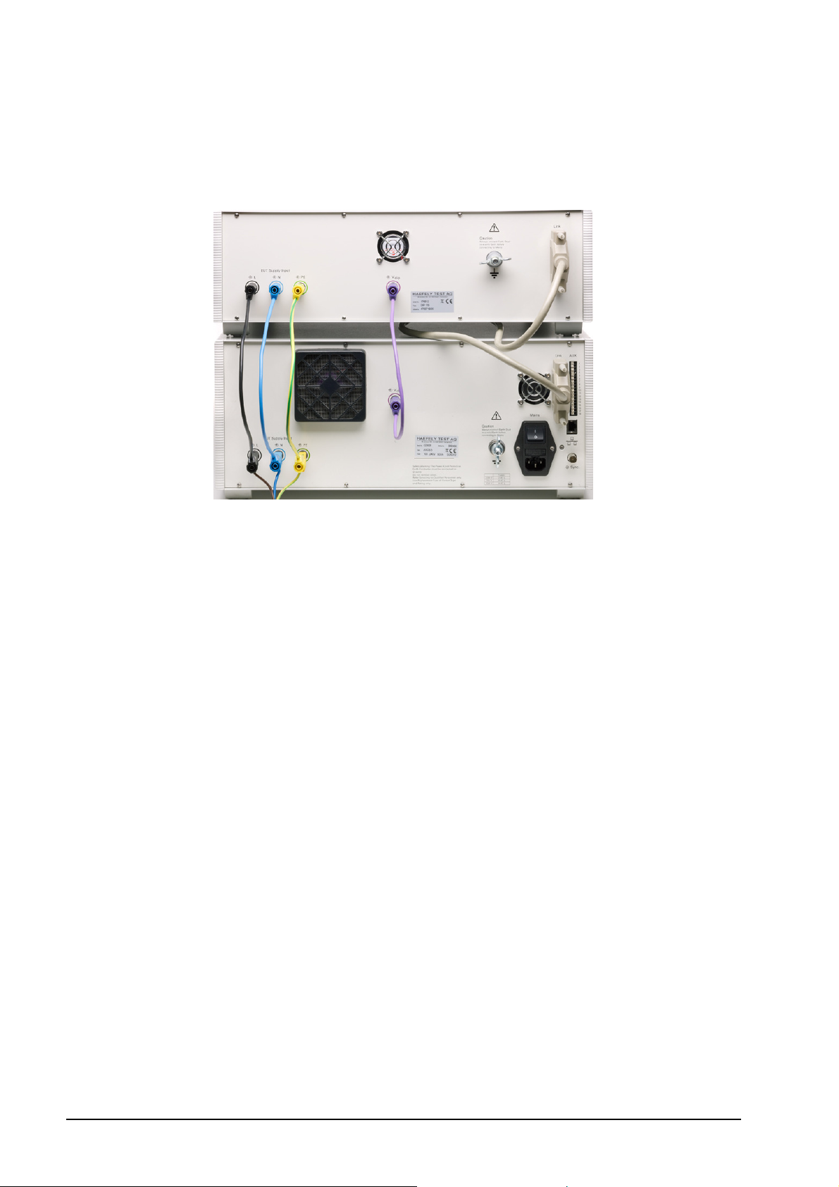
5.2 Rear view
The rear view of the AXOS5 is shown in Figure 5-2. A detailed description of every input and output is written in the
Table 5-2 below the graphic.
6
5
4
7
10
8
1 2 3
9
Figure 5-2: AXOS5 rear view
Pos. Function Description
L “EUT Supply Input” (direct
1
connection of power supply via
banana plug)
N “EUT Supply Input” (direct
2
connection of power supply via
banana plug)
PE “EUT Supply Input” (direct
3
connection of power supply via
banana plug)
V dip (for Voltage dips &
interrupts)
4
“Link” to external HAEFELY
transformer DIP 116
5
6 “AUX” inputs and outputs detailed description of function in Table 5-3
“RJ 45”Ethernet Interface operation of the AXOS5 through an external device, likely a PC for
7
Sync. BNC Interface The BNC interface is used for external synchronization of a
8
9 Main power switch for AXOS5 Switching on/off total power supply
10
Table 5-2: description rear view
Electrical grounding The generator must always be connected to a reference earth
direct single-phase connection of power supply to the EUT. It can
either be connected to a DC power supply or to AC power supply.
Awareness, the power supply should NOT be secured by a ground
fault Switch. If yes please take capture Fehler! Verweisquelle
konnte nicht gefunden werden. in consideration
Input for the voltage dips und interrupts. For voltage interrupts it
has to be connected via banana plug with position 2. However.
when using external transformer, the only connection to the
generator is through the V dip input
Input for HAEFELY transformer DIP 116 for voltage dips, then
adjustable on 0%,40%, 70% and 80% in reference to the U1
nominal voltage of AXOS5. In any other case the transformer has
to be controlled independently and it will be connected only
through the “position 4” with the AXOS5.
the remote software
manual CDN
before every use
5
Compact immunity test System 9
AXOS
Page 16

AUX (Pos. 7.) function description
1 Red warning lamp Indicates when safety circuit closed
2 Green warning lamp Indicates when safety circuit opened
3 GND 0 V
4 GND 0 V
5 Safety interlock When safety barriers installed, connection
must be done between pin 5 and pin 4 to close
the circle (safety instruments), however, bridge
between pin 4 and pin 5 exist as delivery
setting
6 GND 0 V
7 Start/Stop program 1 is running (Input) Start/Stop automatic for starting a predefined
program in the “Setup” menu “start file (Figure
5-3)”, signal for instance external device, PLC
signal
8 GND 0 V
9 Trigger Input Input for external trigger to start for instance
through an external signal a generator
10 GND 0 V
11 EUT Fail (Input) External condition (e.g. device or PLC signal),
the position becomes 1 and causes an action
(Ignore, Alarm, Test Stop or test stop & line off)
12 GND 0 V
13 0-10V Analogue output Reserved and used for further application
14 GND 0 V
15 Trigger output When Burst, Surge or Voltage dips package in
use, signal becomes 0, after the applied
package has finished the signal becomes
1(negation); used for indication of signal on
oscilloscope
16 GND 0 V
17 Spare (Reserve) Not in use
18 GND 0 V
Table 5-3: AUX function description
5.3 SETUP menu
The Figure 5-3 shows the “Setup” menu after selecting this button in the starting field. Every button is explained in the
Table 5-4.
Figure 5-3: Setup menu
In the right upper corner the current software version, serial number can be seen. The FPGA indicates the hardware of
the chip version.
10 AXOS
5
Compact immunity test System
Page 17

Menu field Description
Language Selection of different language, in the moment only English available
Date & Time Entering of current date and time
Sound Volume Adjusting of sound operating volume and warn signals
Report data
saving
Reporting data can be automatically saved when pushing the device in USB port or manually by
pressing the “Rep.Data” in the menu of every application and then entering the device
Start file Selection of predefined test in accordance with particular norm for Surge, Burst, Magnetic field
and Voltage dips & interrupts; it gets only applied from an external start/stop automatic (
Last Calibration Factory calibration from HAEFEY TEST AG, in future term the “next calibration” becomes “last
calibration
Next calibration Recommended calibration period from HAEFELY TEST AG is 2 years, however, it always
depends on the quality management system of every company and certainly the test
requirements of equipment and certification environment
Remote GUI Remote GUI is possible to access when license key purchased from the HAEFELY TEST AG;
switch on/off of communication between remote computer and AXOS5 possible
Coil Antenna Entering of new “coil Antenna” factor as described in
Communication Communication via RJ45 at the rear view of AXOS5
Firmware update For updating the new operating software of the AXOS5
License Manager Entry of license codes for Surge, Burst, Magnetic field and Voltage Dips & Interrupts and remote
GUI. After entering the license code, accessible in main menu
Touch calibration In normal delivery mode there is a pre-calibration of the touch screen. However, if required,
please follow and press for few seconds with a pen the cross at the screen. It requires five
different positions. Then confirming and as a control measure four different yellow dots get open.
Again confirming and the calibration has finished.
Table 5-4: Setup description
After setting has been finished the “Setup” gets closed when pressing the “close” button. Afterwards the starting
window gets displayed. It can be selected between Surge, Burst, Magnetic field and Voltage Dips & Interrupts.
5.4 Predefined standard program
The AXOS5 contains predefined standards test for “Surge”, “Burst”, ”Magnetic field” and “Voltage Dips & Interrupts”
according to each particular norm. Each test can be selected and applied through the Generator to the EUT. The
Figure 5-4 reflects the save and option of data at the “Surge” generator. These application works similar for “Burst”,
“Magnetic field” and “Voltage Dips & Interrupts. The basic understanding of the tool is similar to normal office
applications. Data can be “load”, “Save”, “Save as”, “Copy” and “Delete” as for instance in word. These options occur
on the screen, when “file” button is pushed.
Figure 5-4: Save and load option of data
Two directories can be selected as shown in Figure 5-5. However, the “standard” directory can only read and load the
predefined test procedure in accordance to the particular norm. These files can only be read. The second directory is
“Internal”. The internal data (customized testing files) can be saved, loaded and deleted. Either of the directories can
only be accessed out of the particular menu, like for instance the “surge” generator.
In addition, the loaded program is displayed in the upper line in either of the standard and pre-compliance menu.
5
Compact immunity test System 11
AXOS
Page 18

However, through the “Setup” menu predefined programs can be loaded and applied via an external “start/stop”
device. There get controlled though Pin 7 in Table 5-3. When particular file has been selected, it must be confirmed
with “load”.
Figure 5-5: File selection Internal/Standard
Note: When file wants to be applied and started without any external signal parameter, it must be selected inside the
specific modus (e.g. Surge”) via “load”. However, if controlled from an external signal, it must be selected through the
“Setup” (Figure 5-3) and then confirmed as seen in Figure 5-5. Selection in “setup” menu will not be applied to
generator when not external control of the program.
5.5 Icon bar
The Table 5-5 presents a overview of icons in the operating menu. The icons get displayed in the right upper corner of
the operating menu, except position 3.
Position Symbol function
When button “line” pushed in the operating menu, connection between “EUT supply
1
2
3
4
5
Table 5-5: Icon bar menu
inputs (L, N, PE)” and “EUT supply output (L, N, PE)” is existing; note: no actual “EUT
Supply Input” required for the connection
When circuit closed between PIN 5 and PIN 4 in Table 5-3, either through existing
factory bridge or external circuit connection
When generator charging, symbol gets displayed at touch screen
“Reporting data symbol”, when pushing “Rep.Data” button, this icon comes up in the
right upper corner of the window and the report of the test will be saved via USB-port
on a connected device; Note: only accessible when test has finished
Symbol, when L and N on “EUT Supply Input” are exchanged, therefore, L and N must
be changed back
5.6 Test Report Data
Test report data can be automatically saved to USB memory stick. If "Report Data Saving: Automatic" is selected in the
"Setup" menu, test data are saved automatically after each test. If "Report Data Saving: Manual" is selected, test data
can be saved on the memory stick by using the "REPORT" key within the accordingly menu.
The test data are saved into five CSV files which can easily imported into Excel or similar applications.
Data are saved as follows:
Prg_Log.csv : Test conclusion
Prg_Set_Seq.csv : Test header data
PrgItem002_Log.csv : Test log data
PrgItem002_Set.csv : Test setup data
PrgItem_Res.csv : Test overview data
12 AXOS
5
Compact immunity test System
Page 19

6 Surge
6.1 General information
Please read carefully the Table 5-1 and Table 5-2 in detail before first use of the Surge generator. The short voltage
impulse stays on the EUT during several µs. The peak voltage gets with the Axos5 up to 5 kV. The generator fulfils the
requirements according to the IEC 61000-4-5 norm. The source impedance of the generator is 2 Ω. The HI and COM
signals should be used from the beginning as scheduled, because in extern CDN the polarity becomes important. It
can be select either between the Hi and Com output or the coupling network (Position 9,10,11 in Figure 5-1).
6.2 Combination wave generator
In General waveforms are specified as open circuit voltage (OCV) and short circuit current (SCC). The Surge is applied
directly from the Generator to the Surge HI and COM output, the waveforms are specified in the next two under
captures. The function graphic and the key parameter can be read in the Table 6-1. In accordance to the IEC 60060-1
the front time for the OCV is 1,2 µs ± 30% and the SCC is 8 µs ± 20%.
IEC 60060-1 Definitions
Front time [µs] Time to half value [µs]
Open circuit voltage 1,2 ± 30% 50 ± 20%
Short circuit current 8 ± 20% 20 ± 20%
Table 6-1: Key parameter wave generator
For a detailed description please read the topic “test instrumentation” in the IEC 61000-4-5 norm.
6.2.1 Open Circuit Voltage (OCV)
Figure 6-1: Open circuit voltage (OCV) [1]
Front time: T1 = 1,67 x T = 1,2µs ± 30%
Time to half value: T2 = 50µs ± 20%
Verification of the Surge output signal (HI and COM) in the front view can be done with the help of the in capture 12.1.1
described PDP 8000.
5
Compact immunity test System 13
AXOS
Page 20
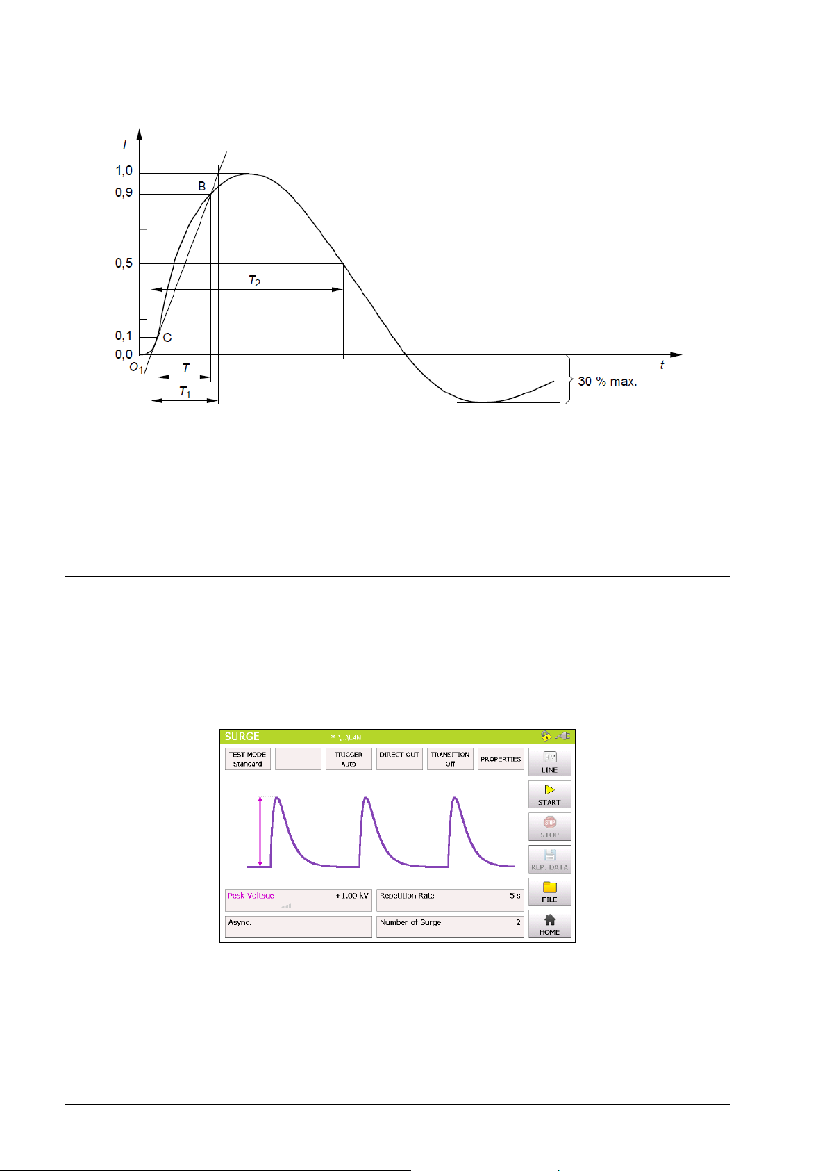
6.2.2 Short Circuit Current (SCC)
Figure 6-2: Short circuit current (SCC) [1]
Front time: T1 = 1,25 x T = 8 µs ± 20%
Time to half value: T2 = 20 µs ± 20%
For verification of the output signal, a current transformer must be connected between position 6 and position 7 as
shown in Figure 5-1. EUT Supply Input must be disconnected. The current transformer from capture 12.1.2 is for the
verification necessary.
6.3 SURGE Menu
Test requirements must be achieved by the user according to the IEC 61000-4-5 norm. The safety standards as written
in Table 1-1 must be unconditionally fulfilled, when operating the AXOS5.
In the next step, the user selects either the pre-compliance or the standard operation mode. The Figure 6-3 and Figure
6-4 reflects either of the appliance modes. As seen by pressing on each particular function parameter a purple bow
comes up and the definition of the function gets displayed.
Figure 6-3: Surge Standard mode
When pressing the “home” button the user gets transferred automatically to the start menu as shown in Figure 2-1.
14 AXOS
5
Compact immunity test System
Page 21

In the Figure 6-4 it shows the use of the pre-compliance mode. Indeed, every parameter can be changed by simply
pressing on the black bows next to the value. Furthermore, it can be changed between direct and line output. All data
entries can be done while the generator is operating.
Figure 6-4: Surge pre-compliance mode
For instance, in the standard mode after selecting the peak voltage field the Figure 6-5 opens up and the parameter
can be entered. In a similar way works the repetition rate and the number of surge. Awareness is to give for line
synchronization; hence, it has been described more detailed in the capture 6.3.5.
Figure 6-5: Surge peak voltage
After values entered, the start button can be pushed and the window Figure 6-6 opens up, if selected pre-compliance
mode.
5
Compact immunity test System 15
AXOS
Page 22

The safety symbol, the direct output and the output voltage and output current are displayed. In addition, the user is
able to see nominal values of the peak voltage, reputation time and the synchronization period. Additionally, these
values can be modified while the test is proceeding. It happens by simply pressing each particular function. The test
stops when pushing the “STOP” button.
Figure 6-6: Surge Pre-compliance mode charging
In the right corner of the graphic is the plug flashing in red, when direct connection between L, N, PE to the “EUT
Supply Input” and button “line” has been pushed. The safety lock symbols shows that the safety circuit has been
closed between PIN 4 and PIN 5 in Table 5-3.
Information about Transition, Trigger and properties has to be entered independently if the test has stopped.
“Transition” and “Trigger” are only accessible in standard operating mode.
6.3.1 Output & Coupling Paths
In the IEC norm 61000-4-5 it is written that every coupling phase has to be tested against each other. That realizes the
AXOS5 with the line output and selecting the options independently. The HI and Com output gets active when in
operating menu “direct” output is selected. L, N, PE can be selected when in “line”.
6.3.2 Properties
In the Figure 6-7 below is the properties menu displayed. The Table 6-2 explains the function more detailed.
Figure 6-7: Surge properties
The Table 6-2 describes the different functions more detailed. The window gets closed, when confirming the “OK”
button.
5
16 AXOS
Compact immunity test System
Page 23

Position Description
External (Pin11 on Aux) External condition (e.g. device or PLC signal), the position becomes
1 and causes an action (Ignore, Alarm, Test Stop or test stop & line
off)
Line Current Limits the current (L, N, PE front view) to the EUT.
Peak voltage It defines an area (min. and max.) within the peak voltage value of
the surge waveform becomes. If not successful, it causes an action,
which can be: Ignore, Alarm, Test Stop or test stop & line off.
Peak current It defines an area within the peak current (min. and max.) value of
the surge waveform can become. If not successful, it causes an
action, which can be: Ignore, Alarm, Test Stop or test stop & line off.
Action: Ignore, Alarm, Test stop, Test
stop & line off
Due to EUT fails, AXOS5 cause an action which can be: Ignore,
Alarm, Test Stop, Test Stop & Line off.
Line off Voltage locked at L, N, PE when test has finished
Line on Voltage unlocked at L, N, PE when test has finished
Sound on or off Acoustic signal when test ends
Table 6-2: Surge properties
6.3.3 Transition
The Figure 6-8 reflects the transition window of the AXOS5. The “alternative polarity” makes possible to switch between
positive and negative. Alternate polarity, peak voltage and phase can be selected and parameter entered. It is only
possible to select phase in either external synchronization or synchronization mode. According to IEC 61000-4-5
alternate polarity at the EUT must be tested.
Significant awareness must be given in the transitions mode, that Trigger “auto” mode is selected, otherwise it is not
possible to access the “Transition” function.
Figure 6-8: SURGE transition mode
After successfully entering the parameter, “OK” button can be pushed and then the “Start” button in the main menu.
Test should be proceeding now.
6.3.4 Trigger
In the trigger window it is possible to select between “auto”, “manual” or “external trigger”. When being in “manual
mode” the user controls the trigger by pressing the start button first, after the generator is charged the menu button
“trigger” flashes up and can be pushed. “Auto mode” provides the signal according to set up and works completely
automatically. All key parameter like “peak voltage” sets the user through the touch screen in the main operating
window. In “external trigger” the signal for the trigger comes from an external source and gets connected via PIN 11 in
the AUX input at the rear view of the AXOS5.
5
Compact immunity test System 17
AXOS
Page 24

6.3.5 Synchronization AC
To synchronize the surge signal with the main supply source it is necessary to adjust in the menu “Synchronization”
and then “Line Sync.”. Further adjustments of the angle can be done in a range from 0° to 359°. However, if no power
supply is connected to the EUT input at the rear view, it has to be entered “Async.”, otherwise it is impossible to get a
Surge impulse of the generator.
In external synchronization, the output with the position 8 Figure 5-2 in the rear view is in use. As an external source
could be used for instance a manual CDN. Normal operation through the touch screen is possible.
18 AXOS
5
Compact immunity test System
Page 25

7 Magnetic field
7.1 General Information
The test setup is described in accordance to the norm IEC 61000-4-9. A SCC waveform will be created. For the
magnetic field the coil gets connected directly via banana plug to the surge output HI and COM as written in position 6
and Position 7 in Figure 5-1. Significant is that only these outputs can be used for the Surge impulse.
Do not touch the coil when the test is proceeding. Do fulfil safety requirements as described in capture 1.1.
In Figure 7-1 is the pre-compliance mode presented. The parameter can be entered by pressing the numbers. For
instance to change the magnet field the parameter “+120 A/m” must be selected and then e new parameter entered.
Figure 7-1: Magnetic field Pre-compliance mode
In addition, the purple bow describes the function. On the top of the window it shows which “Coil Antenna” is selected.
In the standard mode (Figure 7-2) the values can be changed by pressing on the particular parameter as well.
Additionally, the “transition” (capture 8.2.3) can be adjusted.
Figure 7-2: Magnetic field Standard mode
When “Line” button pushed, “EUT Supply Input” connected with L, N, PE front view and in the right corner the plug
flashes red. After pushing the “Start” button the surge impulse gets applied.
5
Compact immunity test System 19
AXOS
Page 26

In Figure 7-3 is the Surge impulse proceeding. The magnetic field will be displayed and the safety symbol is flashing.
The test can be stopped by pushing the “Stop” button. When pushing the “home” button the starting screen as shown
in Figure 2-1 gets displayed.
Figure 7-3: Magnetic field charging
In following points “Coil Antenna”, “Trigger”, “Transition” and “properties” will be described. When being in the “Setup”
menu Figure 5-3, manual has been selected for “rep data”, therefore a test report can be written on a USB device
simply by pressing “Rep.Data”. However, first connect device to USB port.
7.1.1 Coil antenna
When the AXOS5 has started, the setup menu contains a standard predefined coil in accordance to IEC 61000-4-9. It
can be up to 10 different coil factors added to the menu.
Figure 7-4: Coil Antenna factor
To add a different coil, it will be entered in setup (Figure 5-3). This selection can be seen in the operating menu in the
magnetic field.
5
20 AXOS
Compact immunity test System
Page 27

7.1.2 Transition
In “Transition” (Figure 7-5) the user can adjust the “Field Strength”, “Sync. Phase” and “Alternative Polarity”. The
description from capture 6.3.3 is valid, except “peak voltage” has been changed to “field strength”. The other
parameters stay equal, since an OCC will be applied to the coil antenna and is basically a Surge impulse.
Figure 7-5: Magnetic field transition
When all parameters has been entered then simply confirming with ok and in the menu is showing “transition on”, this
indicates the settings will be applied to the coil antenna when pushing the “start” button. Furthermore, when test is
proceeding, the intervals for instance of the “field strength” gets displayed.
7.1.3 Properties
Position description
External (Pin11 on Aux) External condition (e.g. device or PLC signal), the
position becomes 1 and causes an action (Ignore,
Alarm, Test Stop or test stop & line off)
Line Current Limits the current (L, N, PE front view) to the EUT.
Action: Ignore, Alarm, Test stop, Test stop & line off Due to EUT fails, AXOS5 causes an action which can
be: Ignore, Alarm, Test Stop, Test Stop & Line off.
Line off Voltage locked at L, N, PE when test has finished
Line on Voltage unlocked at L, N, PE when test has finished
Sound on or off Acoustic signal when test ends
Table 7-1: Magnetic field properties
5
Compact immunity test System 21
AXOS
Page 28

8 Electrical Fast Transient Burst
8.1 General information
The Burst generator generates Electrical Fast Transient Bursts (EFT) as described in IEC 61000-4-4. The source
impedance of the generator is 50 Ω. The burst is a common mode transient, coupled simultaneously to all selected
paths with respect to ground. It can be selected between using the coaxial output or the built in mains coupling
network.
8.2 BURST TEST
Test requirements must be achieved by the user according to the IEC 61000-4-4 norm. The safety standards as written
in capture Figure 1-1 must be unconditionally fulfilled.
After selecting in the start menu the function “Burst”, the user has the choice between standard and pre-compliance
mode. It gets selected in the top icon bar. The Figure 8-1 shows the standard menu. When pressing “peak voltage”,
“repetition frequency”, “burst duration” a purple bow opens up and describes visually the waveform impulse.
Furthermore, the user can select between “properties”, “trigger manual”, “Burst mode” and “direct out”. Detailed
description is to find in the following under captures. However, when no further adjustment necessary the “Start” button
can be pushed and the window (Figure 8-4) gets open. When pressing the “line” button, the plug in the right corner
flashes red. As a result L, N, PE front view are connected with L, N, PE rear view and full power supply for the EUT is
provided.
Figure 8-1: EFT/BURST Standard mode
By pressing at each particular value, a new parameter (Figure 8-1) can be entered. Then confirming with “OK” and the
parameter will be written in the standard test mode. In Addition it can be immediately selected between kV and V.
Figure 8-2: EFT/BURST peak voltage configuration
5
22 AXOS
Compact immunity test System
Page 29

The following graphic represents the pre-compliance mode. In comparison with the standard menu, every command
gets displayed the entire visual description of the function is described through purple bows. Main advantage of the
pre-compliance mode is that the parameter can be changed while the test is operating.
Figure 8-3: EFT / BURST pre-compliance mode
However, when every parameter has been adjusted, the “Start” button can be pushed and generator is charging. Now,
the following graphic should be displayed. The selected output path (direct or line) is flashing yellow.
Figure 8-4: Burst pre-compliance mode charging
The Burst waveform gets stopped, when pushing the “Stop” button. Afterwards, test report can be saved on the USB
device.
8.2.1 Output & Coupling Paths
In Burst testing mode every line signal gets tested against GND (PE). In direct output the signals stands on the
position 8 in Figure 5-1. It gets connected directly to the EUT or will be used for verification of the Burst waveform.
Furthermore, it can be connected to three-phase test CDN. For further assistance please contact the HAEFELY TEST
AG directly.
5
Compact immunity test System 23
AXOS
Page 30

8.2.2 Properties
The next window shows the property window of the Burst waveform. Detailed description of each parameter can be
read in the Table 8-1.
Figure 8-5: BURST properties
Position Description
External (Pin11 on Aux) External condition (e.g. device or PLC signal), the
position becomes 1 and causes an action (Ignore,
Alarm, Test Stop or test stop & line off)
Line Current Limits the current (L, N, PE front view) to the EUT
Action: Ignore, Alarm, Test stop, Test stop & line off Due to EUT fails, AXOS5 cause an action which can
be: Ignore, Alarm, Test Stop, Test Stop & Line off.
Line off Voltage locked at L, N, PE when test has finished
Line on Voltage unlocked at L, N, PE when test has finished
Sound on or off Acoustic signal when test ends
Table 8-1: BURST properties description
After selection has been finished, the button “OK” must be confirmed and setting gets applied to the Burst generator.
8.2.3 Transition
The Figure 8-6 shows the “transition” menu. It is possible to select independently “peak voltage”, “Repetition
frequency”, “Phase” and “Alternate polarity”. To be able to select “phase” the Synchrony has to be either set as
Synchronization or external Synchronization, otherwise it is not possible to select it. Eventually, every parameter can
be changed by pushing the certain value and entering a new.
Figure 8-6: BURST Transition
When finalizing the parameter, it must be confirmed with “OK” and either the pre-compliance or standard mode gets
open depending on what has been previous operation mode.
5
24 AXOS
Compact immunity test System
Page 31

8.2.4 Trigger
When selecting “manual trigger” the following window opens up. It gets applied to EUT by pressing the “Trigger”
button. It gets always only one Burst package applied.
Figure 8-7: BURST mode Trigger normal
Furthermore, it shows between which line and GND the burst package gets applied. After finalizing the process, it will
be stopped when pushing the “Stop” button. A manual report gets saved on the USB device, after selecting “Rep.Data”
and “manual” selection in the “Setup” menu.
8.2.5 Synchronization
To synchronize the burst signal with the main supply source it is necessary to select in the menu “Synchronization” and
then “Line Sync.”. Adjustments of the angle can be done in a range from 0° to 359°. However, if no power supply is
connected to the EUT supply input at the rear view, it has to be entered “Async.”, otherwise it is impossible to get a
Burst waveform.
In external synchronization, the output with the position 8 Figure 5-2 in the rear view is in use. An external source could
be for instance a manual CDN. Finally, normal operation through the touch screen is possible.
8.2.6 Burst mode
The Burst mode gives the user the option to select between “Normal”, “Continuous”, “Real” and “Random BURST”
signals. Afterwards the function gets automatically displayed on the screen and can be applied to the EUT after
pushing the “Start” button.
5
Compact immunity test System 25
AXOS
Page 32

9 Voltage dips & interrupts
9.1 General information
For the voltage dips & interrupts only the EUT will be only connected through the output (L, N, PE) in the front view.
The EUT Supply Input (L, N, PE) in the rear view gets connected to the power supply. For verification of the signal,
Pos.4 and Pos.5 in Figure 5-1 can be connected to the oscilloscope. Only these five outputs in Figure 5-1 can be used,
when applying or verifying voltage dips & Interrupts at the EUT. Further adjustments of the operation menu will be
described in the following under captures.
9.2 Interrupts
Only the voltage interrupts it is possible to create without an external transformer. To create those interrupts there must
be a connection between V dip and N via banana plug, as seen in Figure 9-1. Additionally, an external powers supply
source has to be connected to EUT supply Input. Afterwards it can be selected between pre-compliance mode and
standard operating menu. The entering of “duration”, “interval”, “test time”, “synchronization” via touch screen by
pressing each specific function (Figure 9-3). When pushing the function name a purple bow opens up and defines the
parameter in the graphic. After successfully selecting the key parameter, the “start” button can be pushed and the
parameter gets applied.
Figure 9-1: Voltage interrupts electrical installation
9.3 Dips
To create the Voltage dips an external transformer is necessary, because a second voltage level is required. When
purchasing the DIP 116 from the HAEFELY TEST AG the position 5 at the rear view graphic can be used. The Figure
9-2 gets displayed when DIP 116 is successfully connected. Exact hardware configuration of DIP 116 is described in
capture 9.3.1. Fully compatibility is guaranteed with the AXOS5.
Figure 9-2: DIP 116 Transformer connected
Only in this case the V dip voltage can be proportionally controlled regarding to the U1 nominal voltage via the touch
screen or via remote software. Moreover all other adjustments are compatible with the AXOS5. Reference voltage
according to the U1 nominal can be selected. V dip can either be 0%, 40%, 70% or 80% in reference to U1 nominal,
26 AXOS
5
Compact immunity test System
Page 33

when using the D116 transformer. The selection happens in the “Dip Voltage” menu field. When selecting 0% it
creates a voltage interrupt, since the V dip becomes 0V.
The Figure 9-3 shows the voltage dips in standard mode. When pushing the particular function name: “Dip Voltage”,
“Line sync.”, “Duration”, “interval” and “test time a visual description gets open with a purple bow as seen below. For
changing the parameter the value has to be pushed, for instance 5 min. New parameter can be entered. When
pushing the button “file” data can be saved and loaded.
Figure 9-3: Voltage Dips Standard mode
The Figure 9-4 represents the pre-compliance mode of the “voltage dips” menu. The purple bows define the function
and show which particular parameter influenced the function. All parameters can be adjusted, when test is operating.
Figure 9-4: Voltage Dips pre-compliance mode (External transformer)
After all parameters have been adjusted and selected the “start” button can be pressed and the voltage dips starting.
Significant, is the right selection of “Line Sync”, “Sync” and “external”. Only in either “line Sync” or “Sync” can the
phase angle be selected, since an external power supply has to be connected, otherwise the synchronization with the
phase would not be technical possible. However, by pushing the “home” button the starting menu as seen in Figure
2-1 gets open.
5
Compact immunity test System 27
AXOS
Page 34
9.3.1 Transformer DIP 116
The HAEFELY TEST AG DIP 116 transformer will be connected through the V Dip and the Link input at the rear view
of the AXOS5. The DIP 116 has an independent connection to an external power supply via banana plug. Once the
setup is done it can be fully automatically controlled through the touch screen of the AXOS5, when being in the menu
field of the “Voltage Dips”.
Figure 9-5: Transformer DIP 116
Then V dip 0%, 40%, 70% and 80% in reference to U1 nominal. Only with the DIP 116 the proportional voltage
adjustment through the menu is possible. The second main advantage will be reflected in the compatibility of the
transformer with the AXOS5 compact immunity tester.
28 AXOS
5
Compact immunity test System
Page 35

9.3.2 External transformer
The only connection from the external transformer (Figure 9-6) with the compact immunity tester happens through V
dip and N’ at the rear view via banana plug. L and N from the external transformer gets connected to the power supply.
The output voltage (between V dip and N) gets displayed as adjusted at the transformer. However, no further
adjustment of the second nominal voltage in the AXOS5 menu possible.
Ext.
Transformer
AXOS5
L
Udip
N
N
Figure 9-6: External transformer
Now the incoming V dip can be regulated directly at the transformer. Note: No further connection of the link data cable
at the rear view possible.
9.3.3 Properties
Position description
External (Pin11 on Aux) External condition (e.g. device or PLC signal), the
position becomes 1 and causes an action (Ignore,
Alarm, Test Stop or test stop & line off)
Line Current Limits the current (L, N, PE front view) to the EUT.
Action: Ignore, Alarm, Test stop, Test stop & line off Due to EUT fails, AXOS5 cause an action which can
be: Ignore, Alarm, Test Stop, Test Stop & Line off.
Line off Voltage locked at L, N, PE when test has finished
Line on Voltage unlocked at L, N, PE when test has finished
Sound on or off Acoustic signal when test ends
Table 9-1: Properties Voltage Dips & Interrupts
5
Compact immunity test System 29
AXOS
Page 36

9.3.4 Transition
The Figure 9-7 shows the “transition” menu. It is possible to select independently “Duration”, “Interval”, “Phase” and
“Alternate polarity”. To be able to select “phase” the Synchrony has to be either set as Synchronization or external
Synchronization, otherwise it is not possible to access it. Eventually, every parameter can be changed by pushing the
certain value.
Figure 9-7: Voltage Dips Transition
When finalizing the parameter, it must be confirmed with “OK” and either the pre-compliance or standard mode gets
open depending what selection was previously done. In addition the incremental intervals get displayed at each
particular function name, like for example “interval”.
9.3.5 Trigger
The trigger can be accessed either from pre-compliance mode or standard mode when generator is not in use. The
user can select after pressing the “trigger” button between: “auto”, “manual” and “external”. In “Auto”: signal gets
applied automatically in accordance to parameters. In “Manual”: pushing the start button after “manual” selection, then
pressing the “trigger” button. In “External”: Signal will be controlled from external source, connection through PIN 11 in
Table 5-3.
30 AXOS
5
Compact immunity test System
Page 37

10 Error Messages
10.1 Error messages
In the menu is a short summary of possible alarm messages which can occur when operating the AXOS5.
10.2 Troubleshooting
Alarm message Possible cause Action needed
Safety Circuit opened close Safety Circuit
tried to start a Test with open Safety Circuit close Safety Circuit and Start
Test again
no file defined in Setup Start File define a Start File
no valid file define a valid Start File
no valid file define a valid Start File
EUT requires more than 16 A support
current, may EUT defect, short circuit EUT
EUT requires more than 16 A support
current, may EUT defect, short circuit EUT,
protection of AXOS5
EUT requires more than 16 A support
current, may EUT defect, short circuit EUT
EUT requires more than 16 A support
current, may EUT defect, short circuit EUT
-check Inominal of EUT (max.
support with AXOS5 16A)
-control EUT independently,
short circuit might occurred,
-External CDN necessary, if
higher Inominal required
1 x beep and automatic shut
down
Table 10-1: Error messages
at system startup any of internal supply
voltages (not 24V) are out of range
at system startup internal supply voltage 24V
is out of range
- bad or missing Function Key
- internal storage card missing or damaged
Frequency of EUT Supply Input is too high use EUT Supply Input voltage
L and N on EUT Supply Input are exchanged Exchange L and N on EUT
5
Compact immunity test System 31
AXOS
send AXOS5 for repair
send AXOS5 for repair
- go to Setup License Manager
and check for correct numbers
- send for repair
with nominal frequency of 50 or
60 Hz
Supply Input
Page 38

10.3 Logic errors
Alarm message Possible cause Action needed
Decrease peak voltage / rep.
Too many spikes per second
frequency / Burst or increase
burst period
Repetition frequency is too high
Decrease peak voltage ,
repetition frequency
burst period / burst duration incompatible
Decrease burst duration / Sync.
time
Incompatible settings
Decrease burst duration /Sync.
Time increase Burst period
Incompatible settings
Increase burst period, repetition
Frequency
Decrease Burst duration, Rep.
Too many spikes per packet
Frequency, Increase Burst
period
Incompatible settings for pre-compliance
mode
Burst mode must be set to
Normal, Trigger must be set to
Auto, Transition must be set off
Incompatible settings
Incompatible settings
Incompatible settings
Entered value out of range
Table 10-2: Logic causes and actions
32 AXOS
5
Compact immunity test System
Decrease peak voltage,
increase repetition rate
Decrease field strength,
increase repetition rate
Decrease dip duration or
increase dip interval
Value must be in the range of
min. and max. value Note:
Similar error can occur, only
with different units, however,
similar action for solving
Page 39

11 Software
11.1 Remote Software
A remote software for the AXOS5 is available. Connection through RJ45 input at the rear view. If further assistance
required, please contact either your HAEFELY TEST AG representative or the sales department of the HAEFELY
TEST AG.
The license code for the “remote GUI” will accessed in the “setup” menu in Figure 5-3 and then in “license manager”.
After entering the license code (Figure 11-1), the “remote GUI” section becomes enabled and it can be either operated
just from the PC or parallel with the touch screen as well. For communication via PC is the IP address required, it is
written in the communication window of the “Setup” menu.
Figure 11-1: License manager
When information and data entered it must be confirmed with “OK”.
5
Compact immunity test System 33
AXOS
Page 40

12 Service
12.1 Verification
In the next under captures are descriptions of our additional verification equipment for the AXOS5. If further information
required of any of the equipment, please either contact your sales representatives or the HAEFELY TEST AG technical
support team directly.
12.1.1 Waveform OCV (Surge)
The HAEFELY PDP8000 is a differential impulse measurement probe that can be used to measure surge pulses. Two
banana plug cables are provided as the High and Common inputs to the PDP8000, and a coaxial output is provided for
connection to an oscilloscope. The divider ratio is 1000:1 and the PDP8000 is rated up to 8kV for surge, 690VAC or
400VDC. The two banana plug will be directly connected to “direct” or “line” output in the front view.
Figure 12-1: PDP 8000
12.1.2 Waveform SCC (Surge)
The current transformer is necessary to verify the SCC waveform. It will be connected with pos.6 and pos.7. Then the
outgoing BNC output creates the connection to the oscilloscope. The SCC gets displayed on the oscilloscope and can
be compared with the parameter as shown in the operation menu from the AXOS5. It represents the signal in
accordance to the IEC 61000-4-4. The same test procedure gets applied for L, N, PE output at the front view.
Significant: Do not connect the “EUT Supply Input” with external power supply at the rear view, when using the current
transformer. It can be directly purchased through the HAEFELY TEST AG or contact your sales representative.
Figure 12-2: Current transformer
34 AXOS
5
Compact immunity test System
Page 41

12.1.3 Electrical fast transient/Burst
The HAEFELY EFT Verification Kit includes a 50 Ω and 1000 Ω attenuator as
required in the IEC 61000-4-4 standard. The appropriate attenuator is fitted to
the “Burst” coaxial output, and an oscilloscope is then connected to the output
of the attenuator. For measuring the waveform at the output of the coupling
filter, single phase and three phase adapters are available. NOTE: Be sure to
disconnect mains power from the “EUT Supply Input” before connecting the
measuring attenuators. Measuring attenuators are designed for burst voltages
only and will be destroyed if subjected to AC/DC voltage.
Figure 12-3: EFT Verification Kit
12.1.4 Burst verification adapter
Additionally, an EFT verification adapter is available for testing of every single
phase (L, N, PE front view from AXOS5). It gets connected with the PE pin
(Pos.12 Figure 5-1) and every single phase (L, N, PE Figure 5-1). The BNC
output of the burst adapter is then connected to the oscilloscope. Do not
connect “EUT Supply Input” to power supply, when verification of burst output.
Figure 12-4: Burst verification adapter
12.2 Calibration
Calibration period of the AXOS5 has to be determined by the user, and depends on the intensity of use and end user
requirements. Typically, a calibration is recommended every 2 years. The AXOS5 is factory calibrated before shipped
and supplied with the calibration certificate.
5
Compact immunity test System 35
AXOS
Page 42

12.3 Recycling
When the instrument reaches the end of its working life it can, if required, be disassembled and recycled.
No special instructions are necessary for dismantling.
The instrument is constructed of metal parts (mostly aluminium) and synthetic materials. The various
component parts can be separated and recycled, or disposed of in accordance with the associated local
rules and regulations.
36 AXOS
5
Compact immunity test System
Page 43

13 Accessories and Options
13.1 AXOS5 Accessories
Article Article number
FP-COMB 32 3-Phase / 32A Power Line CDN Surge & EFT 2490430
FP-EFT 100M2 3-Phase / 100A Power Line CDN EFT 2495860
IP4A Capacitive coupling clamp for EFT 2491300
FP-SURGE 100M2 phase / 100A Power Line CDN SURGE 2490181
PCD 121 Symmetrical Data & Control Line Coupler 2498010
PCD 126A Asymmetrical Data & Control Line Coupler 2498030
DEC 5 Symmetrical Data & Control Line Decoupler 2490141
DEC 6 Symmetrical Data & Control Line Decoupler
DEC 7 Asymmetrical Data & Control Line Decoupler 2490161
DIP 116 Automatic Dips Transformer 16A 40/70/80% 2490410
MSURGE Magnetic Field Test IEC / EN 61000-4-9 2495591
VTM 15000 Isolation Test 1.2/50us up to 10kV 2499960
PDP 8000 HV differential Probe 1000:1 for Surge 2499911
CP 101 Current Probe Model for Surge 2499931
ES External emergency stop Switch P12 4700751
WL External warning Lamp P12 4700750
WinFEAT'R Control, Measurement & Reporting Software 2499701
Calibration Accredited Calibration AXOS5 2490420
Table 13-1: Article for AXOS5
2490151
5
Compact immunity test System 37
AXOS
Page 44

14 Additions
14.1 Addresses
14.1.1 International customer service
e-Mail: EMC-Support@haefely.com
Address: Haefely Test AG
Birsstrasse 300
4052 Basel / Switzerland
Fax : + 41.61.373 45 99
Internet: www.haefelyEMC.com
14.1.2 USA customer service
e-Mail: EMC-Support@haefely.com
Address: Hipotronics Inc.
Department EMC
1650 Route 22
Brewster, NY 10509 / USA
Telephone : (845) 279 3644
Fax : (845) 279 2467
Internet: www.haefelyEMC.com
14.1.3 China customer service
e-Mail: EMC-Support@haefely.com
Address: Haefely Representative Office
8-1-602, Fortune Street
No.67, Chaoyang Road, Chaoyang District
Beijing, China 100025
Telephone : +86 10 8578 8099 / 8199 / 8299
Fax : +86 10 8578 9908
Internet: www.haefelyEMC.com
14.1.4 Manufacturer
e-Mail: EMC-Sales@haefely.com
Address: Haefely Test AG
Birsstrasse 300
4052 Basel / Switzerland
Telephone : + 41.61.373 41 11
Fax : + 41.61.373 49 12
Internet: www.haefelyEMC.com
38 AXOS
5
Compact immunity test System
Page 45

14.2 Glossary of terms and abbreviations
meaning: Helpful hints, notes, tips or remarks
EUT Equipment Under Test
CDN Coupling Decoupling Network
HV High Voltage
LED Light Emitting Diode
IEC International Electro-technical Committee
EN European Norm
ANSI American National Standards Institute
EMC
EMV
DEC Decoupling network
PCD Coupling / Decoupling module (Electrical circuit for transferring energy between networks with
STBY Standby
HV DC High Voltage Direct Current
Hybrid Same as Combination
f.s.d. full scale deflection
meaning: Attention!
Electro Magnetic Compatibility
German equivalent of EMC
the minimum loss and that attenuates the Surge signal so that it does not cause undue
interference to equipment other than the EUT)
5
Compact immunity test System 39
AXOS
Page 46

14.3 Reference
• [1] IEC 61000-4-5 Testing and measurement techniques-Surge immunity test, part 4-5, edt.2, 2005/11
• [2] IEC 61000-4-4 Testing and measurement techniques – Electrical fast transient/burst immunity test, part 4-4,
edt.2, 2004/07
• [3] IEC 61000-4-11 Testing and measurement techniques-voltage dips, short interruptions and voltage
variations immunity tests, part 4-11, edt. 2, 2004/03
40 AXOS
5
Compact immunity test System
Page 47

14.4 Table of figure
Figure 1-1: Safety sign ..................................................................................................................................................... 1
Figure 2-1: Start display ................................................................................................................................................... 2
Figure 4-1: Transformer connection ................................................................................................................................. 7
Figure 5-1: AXOS5 Front view .......................................................................................................................................... 8
Figure 5-2: AXOS5 rear view ............................................................................................................................................ 9
Figure 5-3: Setup menu.................................................................................................................................................. 10
Figure 5-4: Save and load option of data ....................................................................................................................... 11
Figure 5-5: File selection Internal/Standard ................................................................................................................... 12
Figure 6-1: Open circuit voltage (OCV) [1] ..................................................................................................................... 13
Figure 6-2: Short circuit current (SCC) [1] ...................................................................................................................... 14
Figure 6-3: Surge Standard mode.................................................................................................................................. 14
Figure 6-4: Surge pre-compliance mode ........................................................................................................................ 15
Figure 6-5: Surge peak voltage ...................................................................................................................................... 15
Figure 6-6: Surge Pre-compliance mode charging......................................................................................................... 16
Figure 6-7: Surge properties .......................................................................................................................................... 16
Figure 6-8: SURGE transition mode............................................................................................................................... 17
Figure 7-1: Magnetic field Pre-compliance mode ........................................................................................................... 19
Figure 7-2: Magnetic field Standard mode ..................................................................................................................... 19
Figure 7-3: Magnetic field charging ................................................................................................................................ 20
Figure 7-4: Coil Antenna factor ...................................................................................................................................... 20
Figure 7-5: Magnetic field transition ............................................................................................................................... 21
Figure 8-1: EFT/BURST Standard mode........................................................................................................................ 22
Figure 8-2: EFT/BURST peak voltage configuration ...................................................................................................... 22
Figure 8-3: EFT / BURST pre-compliance mode............................................................................................................ 23
Figure 8-4: Burst pre-compliance mode charging .......................................................................................................... 23
Figure 8-5: BURST properties ........................................................................................................................................ 24
Figure 8-6: BURST Transition ........................................................................................................................................ 24
Figure 8-7: BURST mode Trigger normal....................................................................................................................... 25
Figure 9-1: Voltage interrupts electrical installation........................................................................................................ 26
Figure 9-2: DIP 116 Transformer connected .................................................................................................................. 26
Figure 9-3: Voltage Dips Standard mode ....................................................................................................................... 27
Figure 9-4: Voltage Dips pre-compliance mode (External transformer) ......................................................................... 27
Figure 9-5: Transformer DIP 116.................................................................................................................................... 28
Figure 9-6: External transformer..................................................................................................................................... 29
Figure 9-7: Voltage Dips Transition ................................................................................................................................ 30
Figure 11-1: License manager ....................................................................................................................................... 33
Figure 12-1: PDP 8000................................................................................................................................................... 34
Figure 12-2: Current transformer.................................................................................................................................... 34
Figure 12-3: EFT Verification Kit .................................................................................................................................... 35
Figure 12-4: Burst verification adapter ........................................................................................................................... 35
5
Compact immunity test System 41
AXOS
Page 48

14.5 Table of table
Table 1-1: Safety requirements AXOS ............................................................................................................................. 1
Table 2-1: IEC norm covered by AXOS............................................................................................................................ 3
Table 3-1: General data ................................................................................................................................................... 4
Table 3-2: Surge data....................................................................................................................................................... 4
Table 3-3: Burst data ........................................................................................................................................................ 4
Table 3-4: Voltage dips and interrupts data ..................................................................................................................... 5
Table 5-1: Description front view function ........................................................................................................................ 8
Table 5-2: description rear view ....................................................................................................................................... 9
Table 5-3: AUX function description ............................................................................................................................... 10
Table 5-4: Setup description .......................................................................................................................................... 11
Table 5-5: Icon bar menu ............................................................................................................................................... 12
Table 6-1: Key parameter wave generator ..................................................................................................................... 13
Table 6-2: Surge properties............................................................................................................................................ 17
Table 7-1: Magnetic field properties ............................................................................................................................... 21
Table 8-1: BURST properties description....................................................................................................................... 24
Table 9-1: Properties Voltage Dips & Interrupts ............................................................................................................. 29
Table 10-1: Error messages ........................................................................................................................................... 31
Table 10-2: Logic causes and actions ............................................................................................................................ 32
Table 13-1: Article for AXOS5 ........................................................................................................................................ 37
42 AXOS
5
Compact immunity test System
Page 49

15 Appendix
15.1 CE conformity
5
Compact immunity test System 43
AXOS
 Loading...