

Page 1
a brand of
Haefely is a subsidiar y
PD
analog
DDX 9101
Partial Discharge Detector
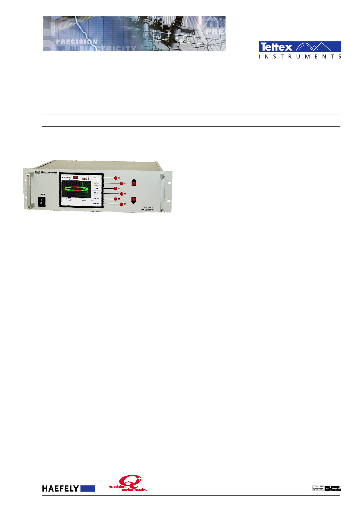
The DDX 9101 partial discharge detector comes from the
very successful family of DDX detectors. It is the ideal
solution for pass/fail partial discharge testing; incorporating
all the basic functions of an analog detector and meets all IEC
and IEEE/ANSI standards for PD testing. We’ve eliminated the
costly advanced features associated with fully computerized
detectors. The DDX9101 simply measures the level of PD and
the applied test voltage. It’s designed to help you modernize
your facility at an affordable price, and it’s simple to operate.
The DDX9101 a straightforward replacement for older analog
detectors of any make or model. The system is housed in a
3U 19” rack mount case designed to slide into a rack cabinet.
Or, if you need a complete new test system, the detector can
be integrated into an AC power supply for production PD
testing of HV components.
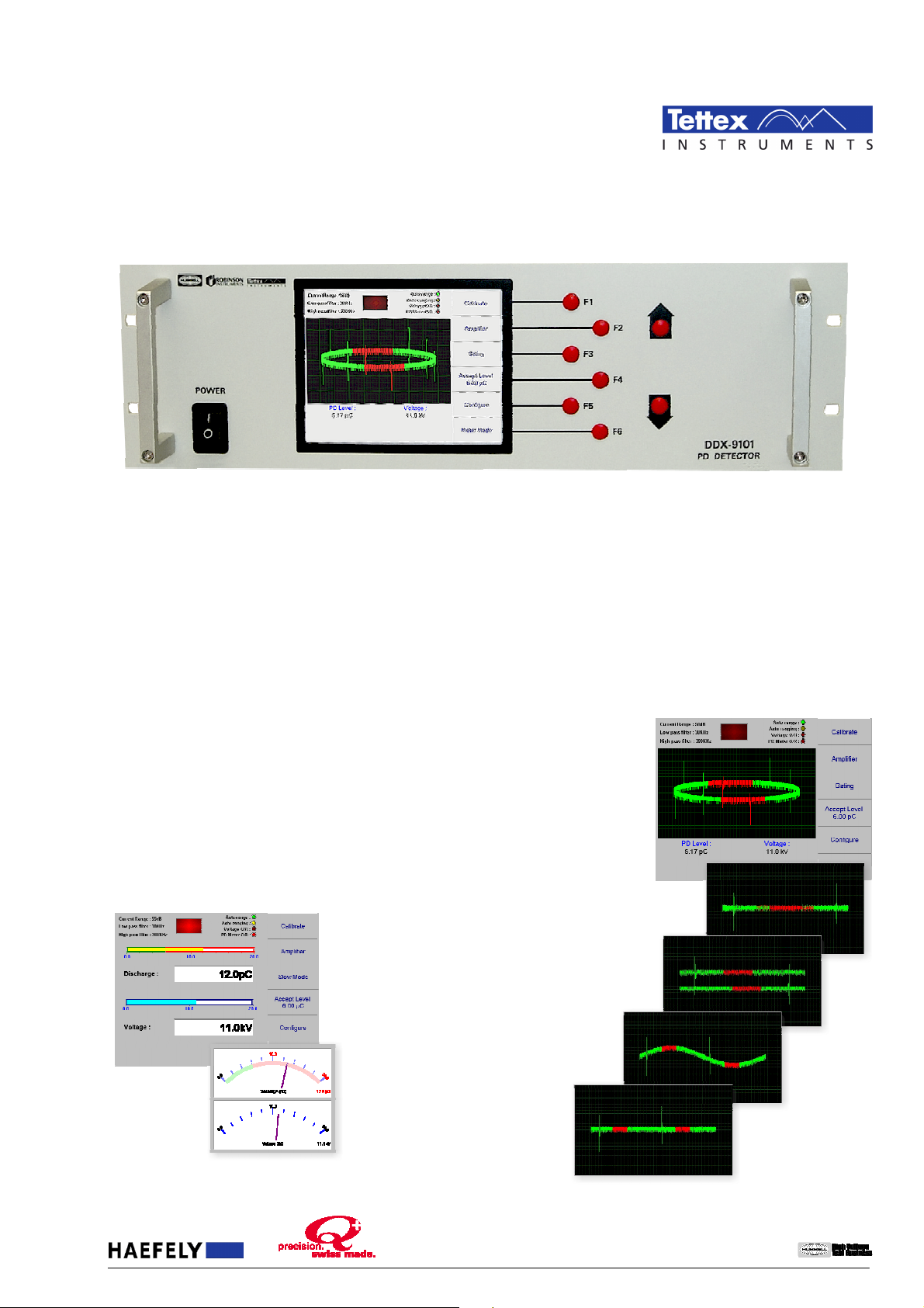
This simple-to-use detector is controlled via 8 control buttons
on the front panel. To operate the detector, select the desired
operation mode (magnitude meter or oscilloscope mode) and
choose the appropriate amplifier settings. Calibrate the
measurement setup, set the maximum acceptable PD level
and you are ready to start the test. Once voltage is applied to
the test object, an indicator on the screen tells you if the test
object passes or fails the test.
With the data acquisition / remote control software and a PC
(optional) the capabilities of the unit are greatly expanded. All
data is acquired during the test according to user-defined
parameters, the data can then be used to generate customized
test reports with graphs and charts. The user can also take
“snapshots” of the ellipse any time during a test. It’s just like
that camera on your old analog scope, only easier.
The most distinguishing feature of the DDX9101 advanced
software is its ability to operate and monitor multiple
detectors simultaneously. If you are a manufacturer
performing routine PD tests in multiple bays, each DDX9101
can now be linked to a single PC enabling remote controls,
monitoring and acquisition of all data.
FEATURES
Settable PD threshold with indicator light when limit is
exceeded
Ethernet port for communication with a PC (optional)
Data acquisition and remote control software package
Two modes of operation - meter mode or scope mode
Compact, 3U (19”) rack mount case is ideal for integrating
into a test system
BENEFITS
Ideal for pass/fail testing – you set the allowable PD level
and the unit determines pass and fail.
Simple to use – 8 buttons on the front panel are all you
need to operate the detector.
Straightforward replacement – if you’ve got an old
unit and need a cost effect, simple replacement
Multiple detectors – with the data acquisition/remote
control software you can operate and monitor multiple
detectors at the same time
Integrated test systems – because of it’s compact design
and functionality this unit is ideal for an integrated PD test
system including an AC power supply
APPLICATIONS
testing of:
Distribution Transformers
Power Transformers
Current and Potential Transformers
Rotating Machines
Switchgears
Surge Arrestors
Cables
Research & Development
Universities
etc.
of Hubbell Incorporated.
Haefely has a policy of continuous product improvement. Therefore w e reserve the right to change design and sp ecification without notice. LL_DDX9101_0707_RF.doc – 1111////4444
Page 2
a brand of
Haefely is a subsidiar y
meters. The light in the middle is the pass/fail indicator for PD
with control and the ability to set/alter the test
Main Screen / Front Panel Details
Test Status Indicator Bar
The test status indicator bar includes three sets of test
indicators to aid during testing. On the left side are the user
selected
On the right side are indicator lights: a
auto-range feature is enabled and
the device is actively auto-ranging. The
O/R
Range, Low Pass Filter
and
High Pass Filter
uto-range
auto-ranging
Voltage
settings.
shows if the
lights when
and
PD Meter
light when the meter reading is beyond the scale of the
levels that are over the user defined limit and shows in red
during a “failed” test.
Function Menu Bar
The six buttons along side (the function menu bar) are used to
enter the parameters and select settings for the unit and the
test. The function menu bar along with the up/down buttons
supply the user
setup.
Main Screen
The test results are displayed on the main screen and two
graphical modes are available to view the test results: meter
mode and scope mode. The threshold shown graphically (in
color) together with different meter modes makes monitoring
of the test results simple.
When operating in meter mode, you have opted to only
view the magnitudes of the partial discharge. In meter mode,
two meters are displayed: one for partial discharge and one
for voltage. You can select two different types of meters: a
traditional analog meter display or a bar-type digital display.
In either mode you select the update rate as either fast or
slow.
The scope mode display looks just like an
oscilloscope. You select the type of oscilloscope
display as an ellipse, straight line or a sine wave.
Gating features are also available in scope mode.
Scope mode gives
you the ability to
see more than just
the magnitude of
the PD and allows a
knowledgeable user
to perform
diagnosis of the
source of the PD.
You can also choose
whether there’s a
single or double
gate, the start point,
and the width to
gate out
undesirable
interferences.
Haefely has a policy of continuous product improvement. Therefore w e reserve the right to change design and sp ecification without notice. LL_DDX9101_0707_RF.doc – 2222////4444
of Hubbell Incorporated.
Page 3
a brand of
Haefely is a subsidiar y
control of the detector from a remote location via the Ethernet
operate
phase
hich they will appear in the test
is where the
is
REMOTE CONTROL / DATA ACQUISITION SOFTWARE
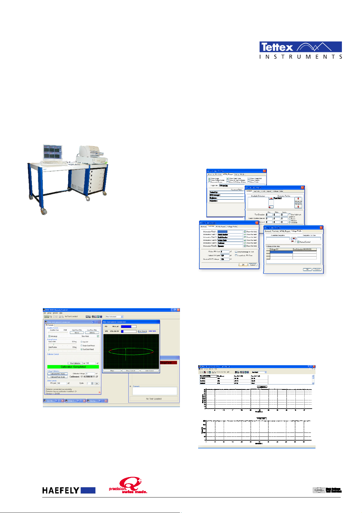
The Remote Control and Data Acquisition software enables
port of a PC. All data is acquired during the test based upon
user-defined parameters. The user can generate customized
test reports with graphs and charts.
The software also provides
the ability to monitor /
more than one DDX at the
same time. For performing
routine PD tests on multiple
test bays, several DDX9101’s
can now be linked to a single
PC providing a single source
for control, monitoring and
data acquisition for all
connected detectors. This can
also be applied to multitesting of transformers.
Test Control
The test control window shows, which DDX is currently
running. This window displays the identification information
for the device under test. It is also where the user has the
ability to start and stop testing on a particular detector.
Measurement Control
This window allows the user to make all the settings as you
would make in manual control mode on the detector(s). All
the available parameters for amplifier settings, gating, filter
settings, choosing the ellipse type and performing voltage
calibration are done from this menu. This is also where the
partial discharge and voltage meters are displayed and where
the threshold indicator is located.
These can then be previewed and saved, deleted, cut/pasted
into another document or printed.
Setup Test Profile
In the Setup Test Profile window there are three tabs to select
from. The
General Tab
is where one selects the detectors that
will be used and the order in w
reports. The time duration for the test and the rate at which
the data for the graphs and the tables are updated are set in
this window.
The
Test Info Tab
is the test identification information for the
test you are performing and the device under test is entered.
Also in this tab is where the user defines the partial discharge
threshold limit for the tests. The
HTML Report Tab
user selects the features of the automatically generated test
reports. Options include logos, borders, and snapshots. This
also where the signature fields on the test report are defined.
Test Reports
The reports are saved as HTML files containing graphs and
charts. In addition all data can be exported as comma
separated value (CSV) format for further analysis or highly
customized test reports in other programs like Excel MS.
Another useful feature of this software is its “snapshot”
capability. At any time during a test you can select the
“snapshot” button. This will give you “photos” (i.e.
snapshots) of the ellipse during that part of the test.
Haefely has a policy of continuous product improvement. Therefore w e reserve the right to change design and sp ecification without notice. LL_DDX9101_0707_RF.doc – 3333////4444
Preview test report Partial Discharge vs. time
of Hubbell Incorporated.
Page 4
a brand of
Haefely is a subsidiar y
IEC-60060 Part 1 & Part 2
IEC-60270
IEC-885-2 and IEC
-
885-3
IEEE Std. 4, 1995
ICEA T
-24-
380
ASTM D1868
-93
ANSI C57.113
ANSI C57.124
-91
TECHNICAL SPECIFICATIONS
Amplifier
Gain (Attenuation) 0 dB to 75 dB in 5 dB steps
Attenuator Accuracy 1 %
Gain 3000
Input Impedance 50 Ω
System Noise
Filters High Pass - 20, 50, 80 kHz
PD Measurement
PD Meter Resolution 10 bits displayed
PD Capture 8 bits (7 plus sign)
Phase Resolution 0.1 %
Linearity Error < 1 %
Voltage Measurement
Uncertainty of Scale
Factor
Linearity (10-100% FS)
Resolution 11 bits
Measurement
modes
Synchronization Local Mains, HV source
Sync Lock range 20 Hz to 400 Hz
Mechanical
Weights 5 kg
Dimensions 19” 3U case, 280 mm deep
Power Supply 100-240 V, 40-70 Hz
Environmental
Operating Temp
Range
Storage Temp
Range
Humidity Range 95% non-condensing
Ethernet Port
Isolated 10BaseT
(note: optically isolated cable recommended)
European Contact
Haefely Test AG
Lehenmattstrasse 353
4052 Basel
Switzerland
+ 41 61 373 4111
+ 41 61 373 4912
[email protected]
< 12 µV referred to input on
highest gain range
Low Pass - 100, 200, 400, 500 kHz
< 1 %
< 1 %
Peak / √2, true RMS
(automatic)
0°C to 40°C
-10°C to 75 °C
Locate your local sales representative at
Applicable Standards
ORDERING INFORMATION
Scope of Supply
PD Detector including:
- Detector in rack mount case
- VM and PD input cables (20 m)
- Input line cord
- 500 VA isolation box
- Users manual
- Calibration Certificate
Accessories and Options
DDX 9101/H Desktop Housing Consult factory
DDX 9104 Internal Calibrator Consult factory
DDX 9101/SWR Data/Acquisition &
Remote Control Software
Coupling Capacitors Consult factory
Calibrator / Two-Pulse Generator Consult factory
High Voltage Calibration Injection
Capacitors
www.haefely.com
DDX9101
DDX9101
DDX9101DDX9101
Consult factory
Consult factory
USA Contact
Hipotronics Inc.
1650 Route 22
PO Box 414
Brewster, NY 10509 USA
+ 1 845 279 8091
+ 1 845 279 2467
of Hubbell Incorporated.
Haefely has a policy of continuous product improvement. Therefore w e reserve the right to change design and sp ecification without notice. LL_DDX9101_0707_RF.doc – 4444////4444
 Loading...