

Page 1
Artikel 0931, 0949
FB 04-200 Rev. 9
Revision: 23.01.2019
Manual
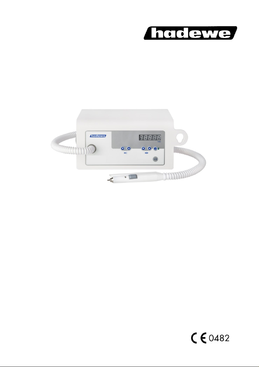
Helius 22
Helius 40
Page 2

2
Directory
Foreword 3
Safety Instructions 4
Cleaning & Disinfection 8
Getting to Know the Unit 9
Before First Use 10
Area of Application 10
Operation 10
Application 12
Operation Steps 12
Working Positioning 13
Suction 15
Exchange Micro Filter 15
Exchange Control Unit Filter 16
Clamping the Bur/Tool 16
Setting up the Speed 16
Foot Switch 16
Maintenance & Care 17
Cleaning the Chuck 17
Maintenance Overview 18
Handling Instructions 19
Troubleshooting 20
Technical Details 21
Page 3

3
Foreword
The Helius foot care unit was produced according to strict quality criteria and uses the
latest technology in its design. The images in this manual may vary slightly from the
product you have bought as the products are constantly being developed.
This user manual includes a detailed description and explanation of how to use the
Helius unit. If you have any questions or suggestions, you can contact us by telephone
or email.
This user manual belongs with the Helius unit. Keep it somewhere safe. If you give this
product to someone else, please include this document as it includes important information on how to correctly use the product.
Short description of functions
The Helius is a medical device for the treatment of callus and nails. The handpiece is
compatible with rotating tools such as diamond polishers, steel cutters and ceramic
cutters. These can reach at speeds up to 40,000 rpm and therefore provide an efficient
way of removing tissue. The direction of rotation can be changed by pressing a button.
The integrated filtered suction function effectively sucks up any dust particles. The
rotation speed and suction function can be adjusted using the keyboard. The device
display will notify you when the filter needs to be changed and when the device is due
for inspection
Page 4

4
Safety Instructions
The equipment should only be used by trained
operators.
The installation of the working area has to correspond to the relevant regulations. Set up the
unit in such a way, that the air slits are not
blocked and the extracted air can escape well.
To avoid the risk of electrocution only connect
the device to the mains power supply.
If you pull the power plug, it will stop the connection to the mains power supply. Set up the
unit so that the power plug is always accessible. The power switch should also always be
easily accessible.
Only switch on the unit if the handpiece rests
secured in the handpiece holder, or if you hold
it safely in your hand.
Prevent any liquids from entering into the
control unit, since this could damage the
electronic elements. Clean the outside of the
box only with a damped cloth. Make sure that
you have unplugged the unit before.
Only when pulling the mains cable, you can
ensure that the device will be completely disconnected from mains. Check the mains cable
regularly for damages and in case of such, it
has to be exchanged or repaired by an au-
Page 5
5
Safety Instructions
thorized service center.
Prevent your hair from wrapping itself around
moving parts. If applicable, wear a hair net.
When working with materials, which might
create dust or moisture, use a drilling unit with
suction or spray technique. Wear a nose and
mouth protection. Always follow the safety
instructions, provided by the manufacturer of
the materials being formed and used.
For safety reasons you must always wear disposable gloves and protective glasses when
operating this unit. In addition, a face mask
conforming to EN 14683 type IIR or EN 149
FFP 2 must also be worn.
Ensure that the patient’s foot and the
handpiece are held firmly in place during the
operation. To prevend injury, work with
extreme caution on the foot of the patient, and
use only light pressure.
To ensure that the bur/tool sits firmly in the
chuck, do not work with tools which:
• have an oily shaft,
• are worn,
• are bent.
Before using the equipment, assure that
• the tool can be pushed far enough into the
Page 6
6
Safety Instructions
chuck (test this with a dipstick and clean if
necessary),
• the inserted tool sits properly in the chuck
and will not cant/jam while clamping it,
• the tool is approved for using it at the maximum speed (see manufacturer’s instructions) or only use the speed required by the
instrument,
• the tool is absolutely dry.
For safety reasons do not change the tool
while the motor is running.
Switch off the unit immediately if
• the bur comes off during the treatment itself.
• the motor blocks during the treatment.
While doing any foot care, only operate the
unit with the suction turned on.
Only use the suction function, if you have installed the suction filter. Check this filter every
10 operating hours. If it is full, please exchange it. A filter should be exchanged at
least after 50 operating hours.
Never use the suction to vacuum any liquids
(or air/water fog which contains particles of
liquids).
Page 7

7
Safety Instructions
Always follow the operating instructions. Do
not carry out any repairs, modifications or
maintenance work yourself. This is only to be
accomplished by an authorized specialist. The
mains cable may also only be changed by the
manufacturer, or an authorized specialist.
Maintenance records may be supplied to repair workshops and trained technicians upon
request. Never remove the housing, especially not while the equipment is plugged into the
socket, since some components are under
electric voltage. Any unauthorized or improper
handling (e.g. trying to repair the unit) of the
equipment will immediately nullify the guarantee/warranty and any other liabilities of the
manufacturer.
Page 8

8
Cleaning & Disinfection
The device is designed to be compatible with rotating in-
struments which do not penetrate the skin or mucosal or
inadvertently may still cause injuries. For this application please
adhere to the cleaning and disinfection instructions provided below. After every treatment please carry out the following steps:
• Remove the rotating tool (e.g. bur, capper etc.) first. Then
handle the tool according to the instructions of its manufacturer.
• Remove tissue remains by wiping off the unit with a mildly
moistened paper cloth. Afterwards clean all surfaces with disinfection cloth (e.g. Mikrozid AF Tücher of Schülke and Mayr)
There is no limit to the number of times this device can be
cleaned and disinfected during its recommended lifespan.
Page 9
9
Getting to Know the Unit
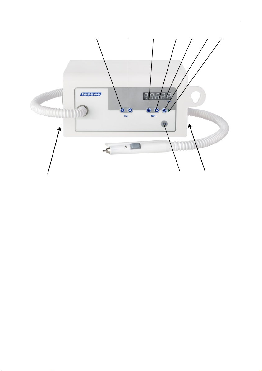
1 decrease the suction output
2 increase the suction output
3 reduce the speed
4 increase the speed
5 display of speed/suction level
6 change direction of rotation
7 LED is ON during reverse rotation
8 main switch
9 ON/OFF button (Standby)
10 connecting socket for foot switch
1 2 3 4 5 6 7
8 9 10
Page 10
10
Before First Use
Please read through the instructions
carefully before using the unit and
carefully note the safety advice.
Always keep this manual accessible
to any users of the drill.
Area of Application
This device should only be used by
people who have completed a foot
care qualification. Before use the
operator should familiarize with the
device by reading this manual or
being instructed by another.
The device must only be used in
closed spaces. It may be used in
hospitals, in a commercial environment or in homes. The device is not
intended for use in operating rooms.
The control unit can be set up in a
cabinet or can be used as a portable unit (e.g. in a carry case). It is
suitable for the following scopes:
• foot care (milling, trimming and
polishing),
• manicure (grinding, milling and
polishing works).
The devise is determined of
operating rotating instru-
ments, which will not
penetrate the skin or murcous
membrane if used appropriate, but
could evoke damages accidently.
Caution: In the area of
pedicure you have to work
with suction techniques.
Operation
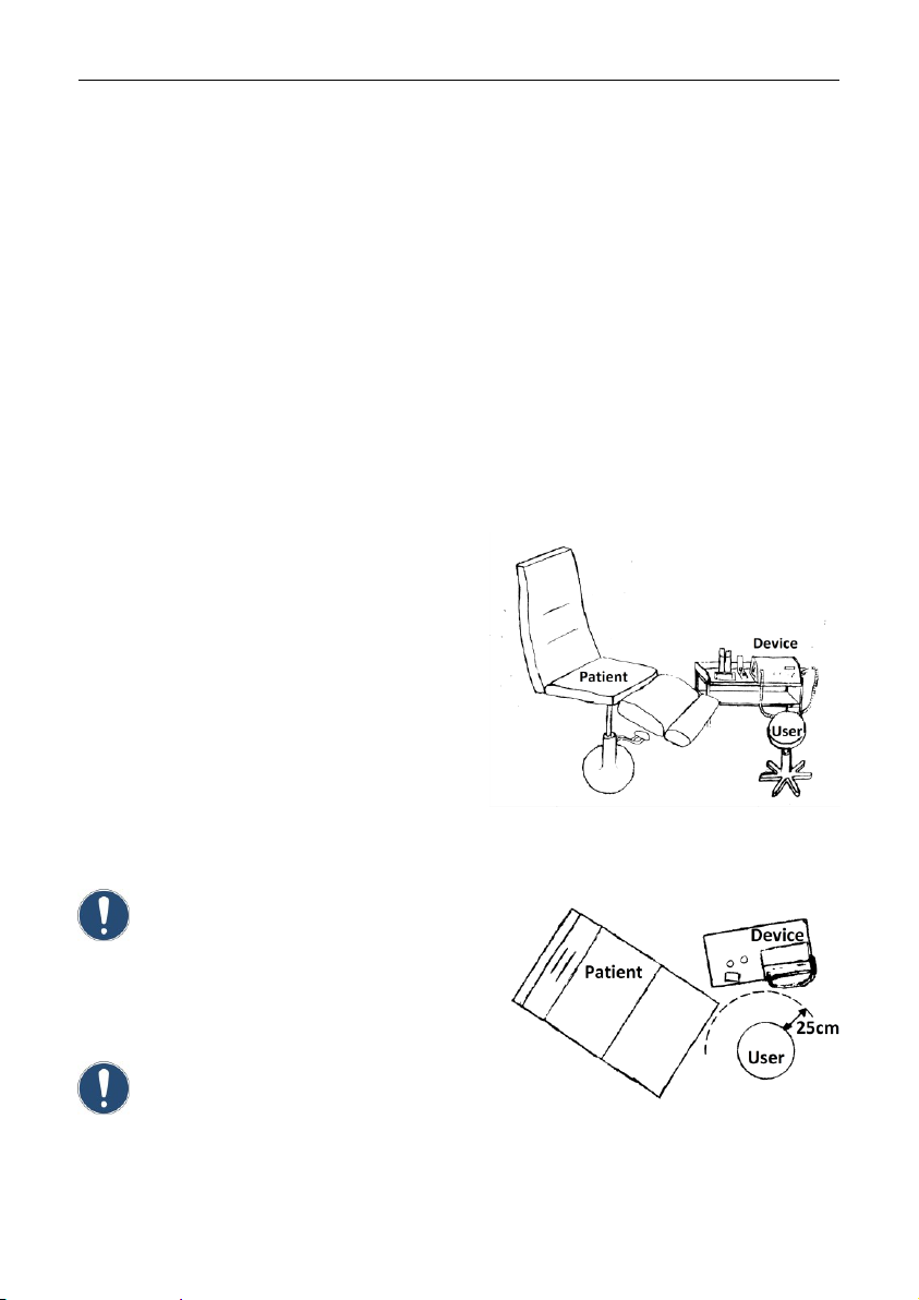
The working area must conform to
the conditions described. Set up the
unit in such a way, that the air slits
are not blocked and the extracted
air can escape well. To guarantee
unhindered air flow there must a
gap of at least 12 cm to the right of
the device.
Position the device so that the operating buttons are easy to reach
and the outlet of the hose is a maximum distance of 60 cm from the
patient's foot. The unit should be
30 – 90 cm from the floor.
Image: Example of positioning of foot care unit
in treatment room
Image: Bird's eye view of work area
Page 11
11
Before First Use
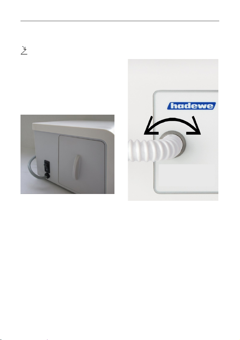
If you have a foot switch, insert its
plug into the port on the right of the
device which displays this symbol
.
Check that the filter bag and dust
filter are correctly fitted. Ensure that
the tool is fixed.
On the left side in the back of the
device you will find the main power
switch. Press this switch to turn the
unit on.
The device is now on standby. Pick
up the handpiece. Should the
handpiece be twisted by the hose
you can adjust that at the control
unit.
To use the handpiece and suction
function press the button (9) on the
front of the unit.
Page 12

12
Application
Operation Steps
In the following section the order in
which you should use the device is
described. Additionally, the individual steps will be explained in detail.
Read the complete manual before
use.
After connecting the device to the
power press the standby button (9)
to make it start rotating. Use the (3)
and (4) buttons to select a rotation
speed. Manufacturers often provide
recommendations for optimal rotation speeds. However, it is important that you never exceed the
maximum recommended rotation
speed.
You can now choose a rotation
direction using the button (6). The
most commonly used direction is
clockwise. Most milling instrument
(steel instruments with steel cutters)
are optimised for clockwise use.
The rotation direction is irrelevant
for diamond cutters and high-grade
corundum sanders in terms of efficiency. Working anti-clockwise can
be beneficial if, for example, the
dust obscures your field of vision
when working clockwise.
Using buttons (1) and (2) you can
adjust the intensity of the suction.
After choosing a rotation speed and
suction power you can start working.
If you want to take a break or finish
the job, press the standby button
(9). The handpiece motor and suction will turn off. The handpiece can
now be placed in its holder on the
right of the unit. Alternatively, you
can switch the device to standby by
pressing the button on the foot
switch.
We recommend you disconnect the
device from the mains power supply
if is not going to be used for a while.
This will save electricity. The mains
plug must also be removed when it
comes to retiring the device.
Page 13
13
Application
Work Positioning
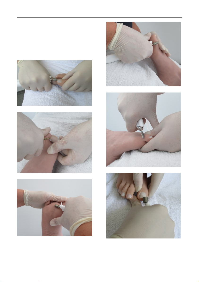
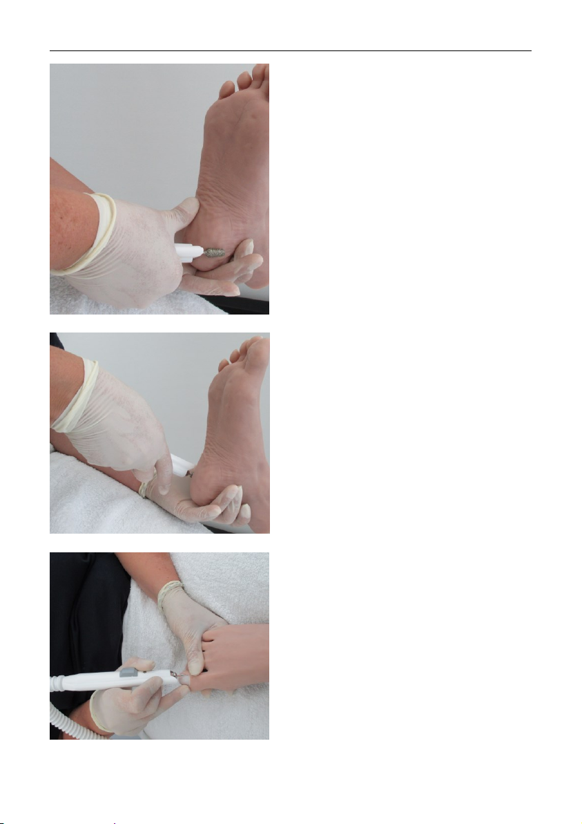
The following images are examples
of how to work on various parts of
the foot. Always make sure that the
foot is firmly gripped and that you
can work freely and without strain.
Page 14
14
Application
Page 15
15
Application
Suction
Switch on the suction with button
(2). The suction output can be regulated in 5 levels. You will see the
selected level in the display. Level 0
would mean that the suction is
turned off.
In case the suction motor overheats, the unit will switch off automatically. Leave the unit to cool off
for a while before starting it again.
Should the same failure appear
again, please return the unit to your
supplier for inspection.
Exchange Micro Filter
When changing the filter, it
is advisable to wear a face
mask conforming to EN
14683 type IIR or EN 149 FFP 2.
Only operate the unit with a suction
filter assembled. Control the filter
bag after every 10 operating hours.
Replace a full filter bag immediately, but no later than FC appears on
the display. You will receive this
message every 50 hours of operation in the suction mode.
You can read the operating time
since the last filter change by pressing and holding button (6) while
pressing the power button at the
same time. First, the five-digit number of the software version of your
device appears, then the operating
time since the last filter change is
displayed.
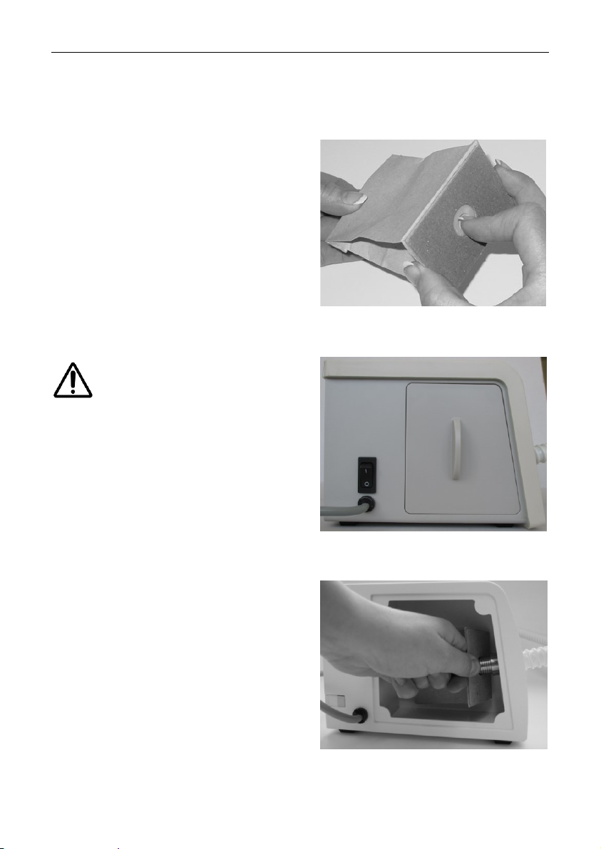
At first, unfold the paper of the paper filter (art. 5115) bag and push
your finger into the opening in the
front.
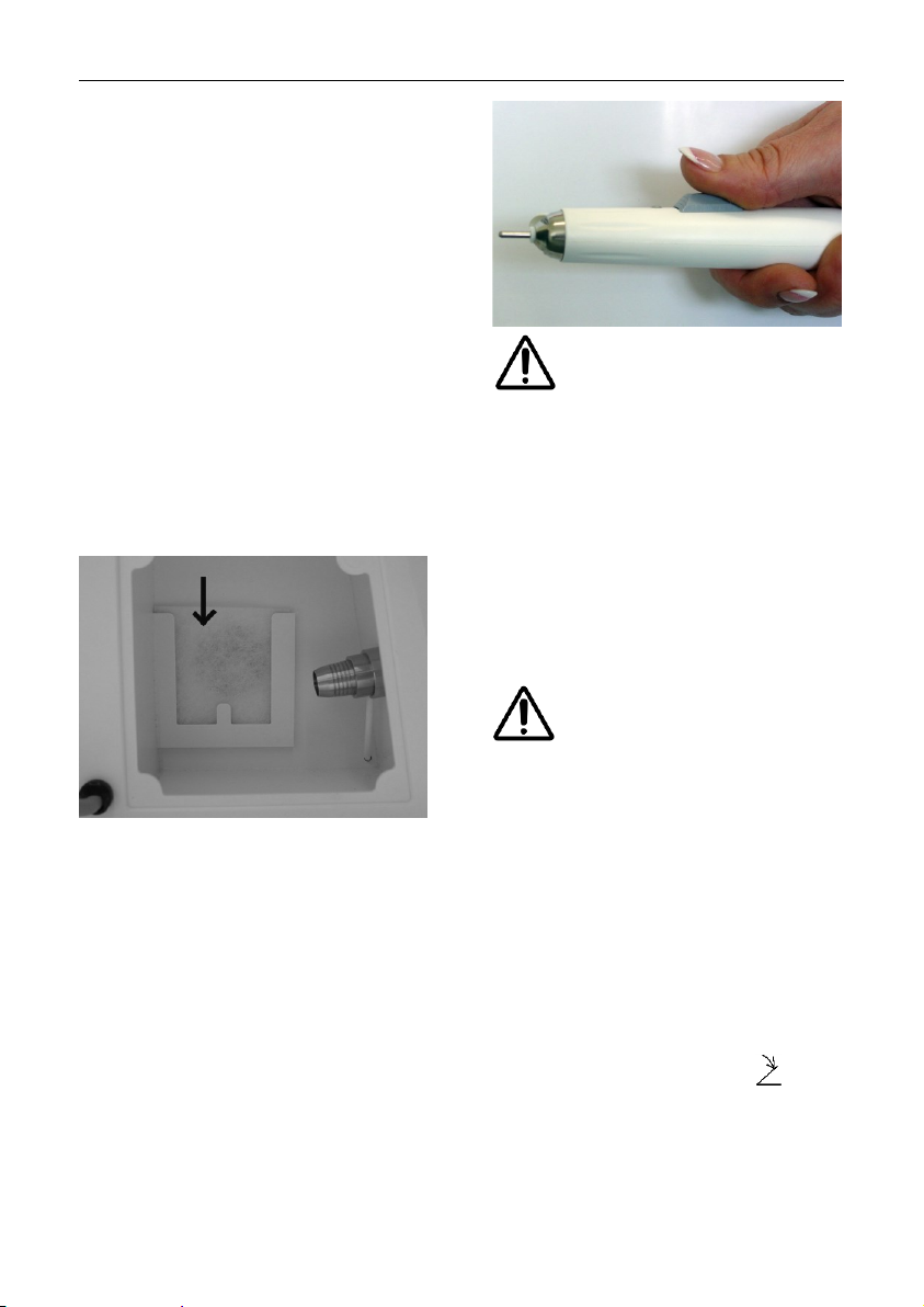
Pull out the lid of the dust chamber
and remove the old filter.
Hold the filter in the middle to prevent it from bending and sliding off.
Page 16
16
Application
As an option you may also use the
micro filter (art. 5179) instead of
paper filter (art. 5115).
After the filter bag has been
changed, the operating time must
be set to zero. To do this, set the
device to standby by pressing button (9). Now hold down button (2)
for five seconds until FC appears in
the display.
Exchange Control Unit Filter
This filter (art. 3752) has to be exchanged after every 200 operating
hours. Remove the old filter and
place the new one in its holder (see
picture).
Clamping the Bur/Tool
The handpiece is equipped with a
chuck, which can hold all burs with
a diameter of 2.35 mm (this is the
diameter usually used for tools in
podiatry). To open the chuck, push
the knob forward with your thumb
and leave it there. Now insert the
tool as far as possible. Pull back the
knob and the tool will be firmly
clamped.
For security reasons, only
change the tool, if the
handpiece is turned off.
Setting up the Speed
Hold the handpiece (incl. tool) in
your hand or store it in the handpiece holder attached to the side of
the control unit. Switch on the unit
with button (9). Now you can also
set the speed with buttons (1) and
(2) and choose its direction of rotation with button (6).
When the device is brought
out of standby mode it will
run with the rotation speed
and suction power used last. Take
care to not start the mill at an overly
high rotation speed. Select the required rotation speed before changing the milling tool.
Foot Switch (art. 0970)
Operation of the foot switch
Only use the original hadewe foot
switch, to avoid any damages. Insert the plug of the foot switch into
the socket with the symbol .
If you press the foot switch for a
longer period, you will switch on/off
the complete control unit.
Page 17
17
Maintenance & Care
Cleaning the Chuck
In the process of time, some dirt
might collect itself within the handpiece, and might affect its functions.
Therefore, the chuck has to be
cleaned monthly.
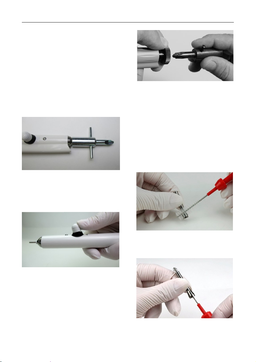
How to remove the chuck
Screw off the top of the handpiece
with the spanner shown in the picture:
Now clean the inside of the handpiece and the top with the brush.
For opening the chuck, push the
button forward:
Set the screw spanner (wrench) on
the axle and hold it tight. Now use
the front of the second spanner to
unscrew the chuck:
To assemble the chuck, follow the
steps in reverse order. Make sure
that the chuck is opened during the
assembly (the handpiece button
must be in forward position) and is
firmly applied afterwards.
How to clean the chuck
Soak the chuck in ethyl alcohol or a
cleaning liquid for tools. Clean the
slits of the chuck with the brush:
Use the brush to remove all dirt
residues from the drill-hole of the
chuck:
Page 18

18
Maintenance & Care
Rinse the chuck very well, and
make sure you let it dry well afterwards. Cover your index finger with
a very little amount (just a drop) of
oil and rub in between your thumb
and index finger. Dab off the oil until
your fingers is only covered with a
very thin film of oil. Now move the
chuck in between your thumb and
index finger. There should be only a
very thin film of oil left on the chuck.
Please act according to the saying:
Less is more.
Maintenance Overview
What has to be
done?
How often?
Done by
whom?
cleaning the chuck
monthly
by user
changing the filter
5115 or 5179
every 50 hours
of operation
by user (check
after each 10
hours)
changing the control
unit filter
every 200 hours
of operation
by user
maintenance by
repair workshop
(changing worn
parts; cleaning;
check leakage current)
every 500 hours
of operation
by repair workshop
Page 19

19
Handling Instructions
Never put the handpiece
into any kind of liquid, and
never oil or grease the
handpiece. Clean its surface with a
damped cloth. Pay attention, that no
moisture or liquid enters the
handpiece. Never use spray
disinfection.
Never put any wet burs or
instruments into the
handpiece. Its moisture
could damage the interior parts of
the handpiece.
Any materials used by
hadewe prevend a formation
of rust. In cases in which a
rust infestation was found within the
handpiece, thorough inspections
and examinations always have
proved that the rust had a foreign
origin (which was usually caused by
the tools used in these
circumstances). Even in high-grade
steel instruments of well known
manufacturers, formation of rust
can appear, e.g., through wrong
treatment with chemical cleaning
and disinfection liquids. This
extraneous rust affects internal
parts of the handpiece in form of
rust bloom and causes pitting.
Therefore, when you not working
with the handpiece, always remove
the bur/tool from it.
Always make sure that you
do not let the handpiece fall
down or exposes it to any
shocks. The ballbearings and the
motor could be damaged by this.
Only work with tools, which are
flawless. Do not work with tools
which
- are bent or out of balance
- whose shaft is worn out or
- are rusty.
Working with faulty tools will
cause a stronger vibration of
the handpiece. A damage of
the ball bearings, clamping technique or motor could be the consequence.
Working with high pressure
will not improve the outcome
of your work, since the motor will even be slowed down. A
second disadvantage is the stronger impact on the ball bearings and
the motor, which will shorten their
life span in the long run.
In case of sending the de-
vice by mail remove the dust
filter before.
Only suck up dust or milling
waste, never suck up larger
particles such as small bits
of cotton wool as this may be get
caught in the handpiece and lead to
blockages.
Page 20

20
Troubleshooting
Handpiece vibrates, is very noisy
and/or becomes warm in the front
part.
Use of bent burs/tools. → Use a different bur/ tool to test this. The
bur/tool itself can be tested with the
hadewe Bur Shaft Tester (art. 4990)
to see if it is bent.
Maximum allowed speed of the tool
was exceeded, which caused a
stronger vibration. → Pay attention
to the tool (e.g. bur, capper and instrument) manufacturers handling
details.
Bur/tool can be inserted only with
difficulty or not at all.
Use of bent burs/tools. → Use a different bur/tool to test this. The
bur/tool itself can be tested with the
hadewe Bur Shaft Tester (art. 4990)
to see if it is bent.
Chuck is dirty. → Clean the chuck
according to the instructions in the
manual.
Bur does not clamp or does not spin.
Chuck is not tightened well. →
Tighten the chuck firmly according
to the instruction in the manual.
Knob of the handpiece cannot be
moved easily.
Chuck is dirty. → Clean the chuck
according to the instructions in the
manual.
Unit does not work at all.
Check, if the main switch of the unit
is turned on at the side of the unit.
Foot switch is used constantly or
faulty. → Pull out the socket of the
foot switch to see if this is the cause.
Pull out the mains plug to reset the
device.
The unit shows different sound levels at different sites of use.
The sound level varies according to
the surroundings of the unit. If you
set up the unit directly in front of a
wall, the sound is reflected stronger,
as if it would, while standing further
away from a wall.
Handpiece motor stutters shortly
(approx. 1 sec) when turning unit on.
In very rare cases this effect did
appear. It will not harm or damage
the device.
Suction function doesn't work.
The suction motor will turn off auto-
matically if it overheats. Let the device cool down before using it again.
Send the device off for inspection if
this occurs repeatedly.
Page 21

21
Technical Details
0931 Helius 22
total weight: 4,0 kg
dimension: W273xH142xD186 mm
input: 230 V~, 50 Hz
power consumption: 0,9 A
vacuum: 2,9 – 5,8 kPa
fuse primary:
F1: 315 mA time delayed safety fuse
F2, F3: 3,15 A time delayed safety
fuse
fuse sec.: thermal fuse
protection class II
accuracy of speed display: ±10%
handpiece:
type B applied part
diameter: 17-22 mm
length: 163 mm
speed: 4.000 - 22.000 rpm
Accessories & Spare Parts
art.
5115
paper filter
5179
micro filter
3752
filter
0970
foot switch
6158
cleaning brush
The clamping system is designed
for rotating instruments, which have
a shaft of 2,35 mm in accordance
with DIN EN ISO 1797-1.
0949 Helius 40
total weight: 4,0 kg
dimension: W273xH142xD186 mm
input: 230 V~, 50 Hz
power consumption: 0,9 A
vacuum: 2,9 – 5,8 kPa
fuse primary:
F1: 315 mA time delayed safety fuse
F2, F3: 3,15 A time delayed safety
fuse
fuse sec.: thermal fuse
protection class II
accuracy of speed display: ±10%
handpiece:
type B applied part
diameter: 17-22 mm
length: 163 mm
speed: 6.000 - 40.000 rpm
Page 22

22
Technical Details
Operating Time
The device is designed for extended usage.
Ambient Conditions
The device is intended for use in
dry closed rooms.
Operation:
temp.: +10°C to +26°C
rel. humidity: 25% to 75%
(not condensed)
air pressure: 700 hPa to 1060 hPa
Storage:
temp: -5°C to +55°C
rel. humidity: 10% to 95%
(not condensed)
air pressure: 500 hPa to 1060 hPa
Transport (up to 4 weeks):
temp: -5°C to +55°C
rel. humidity: 10% to 95%
(not condensed)
air pressure: 500 hPa to 1060 hPa
Safety Check
A safety check must be done in
compliance with the regulations of
the country where the device is
used. The inspection interval is
once a year.
Repeated control and control after
repair (DIN EN 62535, VDE 0751-1)
Inspection interval for repeated
control: 1 year
Technical Information:
Safety class: II
Application: Type B (separate
measuring of discharge current not
necessary)
Power connection: NPS (nondetachable power connection)
The protective ground conductor is
not connected to touchable conductive parts.
Necessary function inspection:
speed, display, on/off, suction/spray, clamping system.
Inspection before use
During the production control the
following inspections as per DIN EN
62353 (VDE 0751-1) are conducted
among others:
Optical control, unit discharge current <500µA, discharge current at
applied part <500µA
Functional inspection of display,
on/off-button, suction/spray, speed
and clamping system. Safety and
function deficiencies have not been
found. By providing this information
an inspection before use can be
renounced as per DIN EN 62535,
which otherwise would have to be
ordered by the user.
Compulsory Registration
Operators, distributors and retailers
who were informed about the occurrences regarding §29 of the Medical
Devices law must report this. The
method of reporting is detailed in
the Medical Devices Safety Plan
Ordinance. Outside of Germany the
corresponding local conditions apply.
Page 23
23
Technical Details
Disposal
The device and filter may
contain infectious material
such as residual sanding
dust or skin particles. Therefore,
please bear in mind the following
disposal instructions.
Disposing of the device
Old devices bought in Germany that
correspond to the electronic device
law should be sent directly to the
manufacturer (hadewe). We will
dispose of the device free of
charge. The devices should not be
taken to public disposal plants
(WEEE Reg.-Nr. DE20392713, b2b
device). For disposal of this unit out
of Germany, please contact the site
where you bought this hadewe
product.
Note for the disposal of the device/
treatment system
Wear protecting gloves of the class
2 in accordance with DIN 374-2
during the disassembling of the
device. Also, wear a protective
mask for your face according EN
14683 version IIR or EN 149 FFP2.
Disposal of dust filter and coarse
dust filter
The filter bag and the coarse dust
filter are considered low contaminated waste. Dispose those in in
transparent, liquid- tight, resistant
plastic sacks and do not dispose
them compressed in the regular
household garbage.
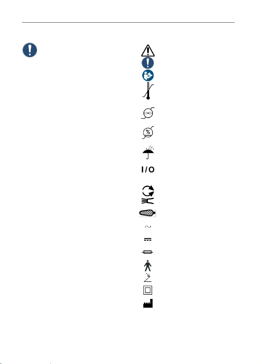
Symbols
Caution!
Important Note!
Follow instructions for use!
temperature limit
(indicates the lower and
upper temperature limit)
air pressure: permissible
range
air humidity: permissible
range
Keep dry!
ON/OFF button (standby) (no
disconnection from main
power supply)
change direction
suction
rotation
alternating current
direct current
safety fuse
type B applied part
socket foot switch
class II
date of manufacture,
name and address
of the manufacturer
Page 24
Technical Details
24
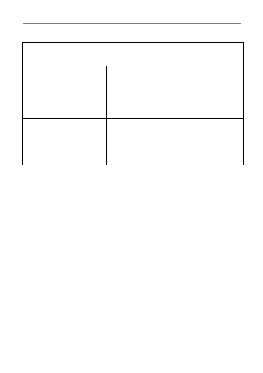
Information on electromagnetic compatibility according to DIN EN 60601-1-2
Guidance and Manufacturer's Declaration – Electromagnetic Emissions
The device is suitable for use in the specified electromagnetic environment. The customer and/or
the user of the pa-on should assure that it is used in an electromagnetic environment as described below:
Emissions Test
Compliance
Electromagnetic Environment – Guidance
RF emissions according to CISPR
11
Group 1
The device uses RF energy
only for its internal function.
Therefore, its RF emissions
are very low and are not
likely to cause any interference in nearby electronic
equipment.
RF emissions according to CISPR
11
Class B
The device is suitable for
use in all establishments,
including domestic establishments and those directly
connected to the public lowvoltage power supply network that supplies buildings
used for domestic purposes.
Harmonic emissions IEC 61000-32
Class A
Voltage fluctuations/flicker emissions IEC 61000-3-3
not Applicable
Page 25

Technical Details
25
Guidance and Manufacturer's Declaration – Electromagnetic Immunity IEC 60601-1-2
The device is suitable for use in the specified electromagnetic environment. The customer
and/or the user of the device should assure that it is used in an electromagnetic environment
as described below:
Immunity Test
IEC 60601 Test
Level
Compliance Level
Electromagnetic Environment –
Guidance
Electrostatic
discharge
(ESD)
IEC 61000-4-2
± 6 kV contact
discharge method
± 8 kV air discharge method
± 6 kV contact
± 8 kV air
Floors should be wood, concrete, or ceramic tile. If floors are
covered with synthetic material,
the relative humidity should be
at least 30 %.
Electrical fast
transient/burst
according to
IEC 61000-4-4
± 2 kV for power
supply lines
± 1 kV for input/output lines
ot applicable
Mains power quality should be
that of a typical commercial
and/or hospital environment
Surge according to
IEC 61000-4-5
± 1 kV differential mode
± 2 kV common
mode
not applicable
Mains power quality should be
that of a typical commercial
and/or hospital environment.
Voltage dips,
short interruptions and
voltage variations on power
supply input
lines IEC
61000-4-11
< 5 % UT (>95
% dip in UT) for
½ cycle
40 % UT (60 %
dip in UT) for 5
cycles
70 % UT (30 %
dip in UT) for 25
cycles
< 5 % UT (>95
% dip in UT) for
5 seconds
not applicable
Mains power quality should be
that of a typical commercial
and/or hospital environment. If
the user of the device requires
continued operation during
power mains interruptions, it is
recommended that the device be
powered from an uninterruptible
power supply or a battery.
Power frequency (50/60
Hz) magnetic
field IEC
61000-4-8
3 A/m
3 A/m
Mains power quality should be
that of a typical commercial
and/or hospital environment.
NOTE UT is the a.c. mains voltage prior to application of the test level.
Page 26
Technical Details
26
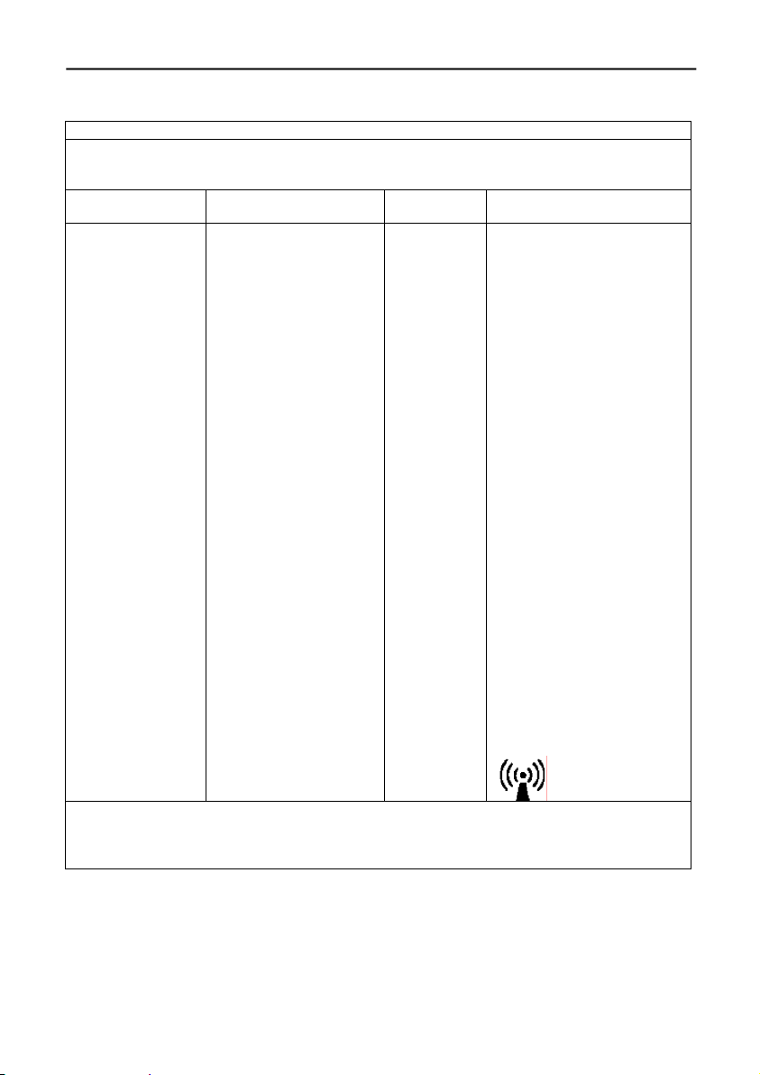
Guidance and Manufacturer's Declaration – Electromagnetic Immunity IEC 60601-1-2
The device is suitable for use in the specified electromagnetic environment. The customer
and/or the user of the device should assure that it is used in an electromagnetic environment
as described below:
Immunity Test
IEC 60601 Test Level
Compliance
Level
Electromagnetic Environment – Guidance
Conducted RF IEC
61000-4-6
Radiated RF IEC
61000-4-3
3 Vrms 150 kHz to 80
MHz
3 V/m
80 MHz to 2,5 GHz
3 Veff
3 V/m
Portable and mobile RF
communications equipment
should be used no closer to
any part of the pa-on, including cables, than the recommended separation distance
calculated from the equation
appropriate for the frequency of the transmitter.
Recommended Separation
Distance:
d = 1,17 √P
d= 1,17 √P 80 MHz to 800
MHz
d = 2,3 √P 800 MHz to 2,5
GHz
where P is the maximum
output power rating of the
transmitter in watts (W)
according to the transmitter
manufacturer and d is the
recommended separation
distance in meters (m).
Field strengths from fixed
RF transmitters, as determined by an electromagnetic
site survey, a should be less
than the compliance level in
each frequency range
Interference may occur in
the vicinity of equipment:
NOTE 1 At 80 MHz and 800 MHz, the separation distance for the higher frequency range
applies.
NOTE 2 These guidelines may not apply in all situations. Electromagnetic propagation is affected by absorption and reflection from structures, objects, and people.
Page 27
Technical Details
27
a) Field strengths from fixed transmitters, such as base stations for radio (cellular/cordless)
telephones and land mobile radios, amateur radio, AM and FM radio broadcast, and TV broadcast cannot be predicted theoretically with accuracy. To assess the electromagnetic environment due to fixed RF transmitters, an electromagnetic site survey should be considered. If the
measured field strength in the location in which the device is used exceeds the applicable RF
compliance level above, the device should be observed to verify normal operation. If abnormal
performance is observed, additional measures may be necessary, such as re-orienting or relocating the device.
b) Over the frequency range 150 kHz to 80 MHz, field strengths should be less than 3 V/m.
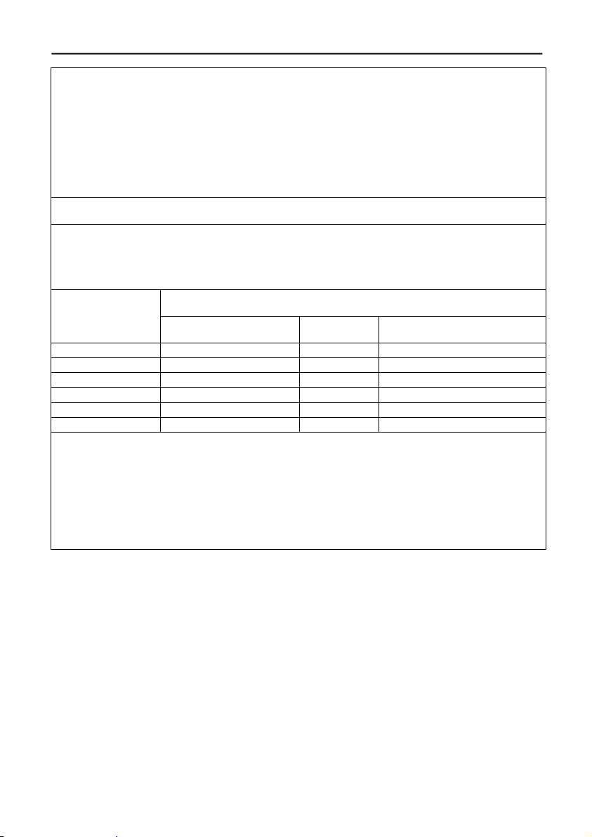
Recommended Separation Distances between Portable and Mobile RF Communications
Equipment and the pa-on Parometer IEC 60601-2
The device is intended for use in an electromagnetic environment in which radiated RF disturbances are controlled. The customer or the user of the device can help prevent electromagnetic
interference by maintaining a minimum distance between portable and mobile RF communications equipment (transmitters) and the pa-on Parometer as recommended below, according to
the maximum output power of the communications equipment.
Rated maximum
output power of
transmitter
W
Separation distance according to frequency of transmitter m
150 kHz to 80 MHz in
ISM bands
80 MHz bis
800 MHz
800 MHz to 2,5 GHz
d = 1,17 √P
d= 1,17 √P
d= 2,3 √P
0,01
0,12
0,12
0,23
0,1
0,38
0,38
0,73
1
1,2
1,2
2,3
10
3,8
3,8
7,3
100
12
12
23
For transmitters rated at a maximum output power not listed above, the separation distance can
be estimated using the equation in the corresponding column, where P is the maximum output
power rating of the transmitter in watts (W) according to the transmitter manufacturer.
NOTE 1 At 80 MHz and 800 MHz, the separation distance for the higher frequency range applies.
NOTE 2 These guidelines may not apply in all situations. Electromagnetic propagation is affected by absorption and reflection from structures, objects, and people.
Page 28

hadewe GmbH
Grambartstraße 10
30165 Hannover
Germany
[email protected]
www.hadewe.de
 Loading...