

Page 1
Page 2

Table of Contents
Cautions
1. Introduction ...................................................................................................................... 1
1-1. Features .................................................................................................................... 1
1-2. Clinical applications ................................................................................................... 1
1-3. System requirements ................................................................................................. 1
2. Appearance ...................................................................................................................... 2
2-1. Smartdop XT ............................................................................................................. 2
2-2. Probes ....................................................................................................................... 4
2-3. Smart-XT-Link for 6 ports for Windows ...................................................................... 5
3. Getting started ................................................................................................................. 6
3-1. Charging battery ........................................................................................................ 6
3-2. Software installation................................................................................................... 6
4. Testing ............................................................................................................................. 8
4-1. Starting operation ...................................................................................................... 8
4-2. Automatic Arterial Testing (Oscillometry) ................................................................... 9
4-3. Further segmental studies ....................................................................................... 13
4-4. Doppler Arterial Testing............................................................................................ 15
4-5. PPG Venous Reflux ................................................................................................. 19
4-6. Foot Temperature .................................................................................................... 21
5. Menu .............................................................................................................................. 23
5-1. SaveFile .................................................................................................................. 23
5-2. Search Files............................................................................................................. 23
5-3. New File .................................................................................................................. 24
5-4. Print Report ............................................................................................................. 25
5-5. Patient Information .................................................................................................. 25
5-6. Symptoms/ Diagnosis .............................................................................................. 25
5-7. Default Data ............................................................................................................. 26
5-8. Option Screen .......................................................................................................... 26
6. Maintenance .................................................................................................................. 28
6-1.Performance check by user ...................................................................................... 28
6-2.Cleaning ................................................................................................................... 28
6-3.Warranty ................................................................................................................... 28
7. Supplemental information .............................................................................................. 29
7-1. Symbol List .............................................................................................................. 29
7-2. Contents of package ................................................................................................ 29
7-3. Options .................................................................................................................... 30
8. Technical information ................................................................ ................................ ..... 30
8-1.Principles .................................................................................................................. 30
8-2.Block diagram ........................................................................................................... 32
8-3.Specifications ........................................................................................................... 33
8-4.Safty standards ......................................................................................................... 34
Page 3

Cautions
Please read the following important points carefully before you operate the unit.
1. Only skilled people should operate the unit.
2. Use the unit for intended use described in "§1-2. Clinical applications".
3. Do not apply any modification to the unit.
4. Device placement:
Take care of storage and operating environments.
(1) Do not place it near water.
(2) Do not put anything where disconnecting power supply of the unit could be
obstructed.
(3) Do not place it where atmospheric pressure, temperature, humidity, ventilation,
sunlight, dust, salt, sulfur and so forth will not affect the unit adversely.
(4) Pay attention to the stability conditions to avoid too much inclination, vibration,
shock and so on during transportation and installation of the unit.
(5) Do not place it where chemicals are stored or where gas may be generated.
(6) Do not place it where the unit tends to fall.
(7) Do not place it on or adjacent other electronic device.
5. Before use:
(1) Make sure that the computer works properly for Smart-XT-Link.
(2) Make sure that the unit operates safely and correctly by implementing simple
check before use mentioned in "§ 6-1. Performance check by user".
(3) Make sure that all cables and components are connected correctly and safely.
(4) Using it with other equipment together may cause a misdiagnosis or danger to
patient due to a malfunction.
(5) Double-check that all the cables and components do not obstruct any external
connection to the patient.
(6) Do not sterilize the main unit by gas, autoclave or so on to prevent any damage.
6. Operation:
(1) Do not use the unit simultaneously with either electric cautery, cardioverter, other
ultrasonic device or mobile phone.
(2) Be careful not to exceed time and volume of diagnosis treatment required.
(3) Always watch so the unit and patient are not under abnormal conditions.
(4) When any abnormality is found on the unit or the patient, take proper action such
as stopping use of the unit in a manner safe for the patient.
(5) In case of emergency or unexpected situations, take the following action(s) to stop
the inflation of the cuffs:
• Press STOP button on the front panel of the unit.
• Disconnect the tubing of cuff from the unit.
• Turn the unit off.
(6) Do not let the patient touch the unit.
(7) Use the designated components only.
Page 4

(8) Do not use the components for other devices.
(9) Use the unit under the operating environments specified on the specifications.
(10) Use the unit as specified in the operating manual.
(11) Do not use the unit in a strong electromagnetic field or it may cause incorrect
measurements.
7. After use:
(1) Do not apply excessive force to disconnect the cables by pulling them too strongly.
(2) Clean the unit, tubing, probes and AC adaptor and place them in right place for the
next use.
8. Storage:
(1) Follow the caution # (1) to (5) of section #4 in the previous page.
(2) Clean the unit, components, cables and probes and place them in right place for
the next use.
(3) When using the unit next time, perform the maintenance to make sure it works
properly and safety.
9. Maintenance:
(1) Do the periodical maintenance by following the procedures mentioned in Ҥ6-1.
Performance check by user”.
(2) The maintenance must be done at least once a year.
10. Probes:
(1) Clean the probe using damp cloth before use. Using alcohol or thinner may
damage the probe.
(2) The probe transducer tip is very thin and delicate. Please handle with great care
and use the probe cap when not in use.
11. Ultrasonic gel:
(1) Do not apply ultrasonic gel to the Doppler probe body other than the tip of probe
(2) Using other materials such as baby oil and cream may damage the probe.
(3) The ultrasonic gel enclosed is non-sterile and do not use it for surgeries.
(4) Incidence of allergy: Discontinue use of gel if an allergic reaction occurs.
12. Battery:
(1) When battery is low, the power indicator blinks in green. If it’s extremely low, the
unit will not operate. Charge the battery.
(2) Battery life is 300 full charges. When full charged life becomes obviously short,
contact your dealer for replacing battery.
13. For transportation of the unit, it should be packed properly to protect against shock.
14. Repair services:
(1) When the unit gets out of order, contact the dealer for repair from whom you
purchased the unit.
(2) Only authorized people should perform the repair services.
15. Do not disassemble the unit.
Page 5

16. Destruction:
(1) In case of destruction of the unit, follow the instructions for disposal of the
destruction appointed by each country or local government.
(2) Do not throw battery in a fire or it may cause an explosion and injury.
17. Connection to computer:
(1) Any connected computer is not allowed to be in the patient area according to
EN60601-1.
(2) Use the computer confirming with EN60601-1 to connect to the unit.
(3) Connection of the connected computer to a network that includes other equipment
such as network printer could result in previously unidentified risks to patients, or
operators and the user of the unit should identify, analyze, and control such risks.
(4) Subsequent changes to network could introduce new risks and require new
analysis; and changes to network include:
(a) Connection of additional items to network
(b) Disconnecting items from network
(c) Update of equipment connected to network
(d) Upgrade of equipment connected to network
Page 6

Page 7

1
1. Introduction
Thank you very much for choosing the Smartdop XT.
The Hadeco Smartdop XT is a fully automatic total vascular testing system for ABI and TBI
studies that works with a Windows software Smart-XT-Link including automated blood
pressure & pulse volume measurement capabilities for up to 6 sites with simple one-button
operation as well as up to 14 sites with rolling basis segmental testing.
Please read this manual carefully to acquaint yourself with the unit operation.
This medical device can be used for the purposes mentioned in "Clinical Applications" for
patients in hospitals and clinics.
1-1. Features
One button operation for up to 6-site automatic blood pressure measurements by
oscillometry & PPG for ABI, TBI, and PV-Arterial studies.
Up to 6-site semi-automatic blood pressure measurements by Doppler & PPG for
ABI & TBI along with Doppler and PV arterial studies.
Segmental blood pressures for up to 14 sites with rolling basis operation
PPG Venous reflux study with dual PPG probes.
Foot temperature study available with optional temperature probe.
All tests controlled & stored by computer with Smart-XT-Link for Windows that
includes capabilities to print waveform data and export to DICOM.
1-2. Clinical applications
To diagnose peripheral vascular disease:
ABI and TBI studies
Blood pressure segmental studies
PV arterial studies
Bi-directional Doppler lower extremity studies
PPG toe pressure & venous reflux studies
Foot temperature studies
1-3. System requirements
MAIN UNIT: Smartdop XT
SOFTWARE: Smart-XT-Link for 6 ports for Windows
COMPUTER
OS: Windows Vista/ 7/ 8.1
CPU clock: Celeron 1GHz or more
Display: 800 x 600 dots or more
256 colors or more
Minimum memory requirements:
RAM: 1 GBytes or more
HDD: 40 MBytes or more
USB: USB2.0 or more
Page 8
2
2. Appearance
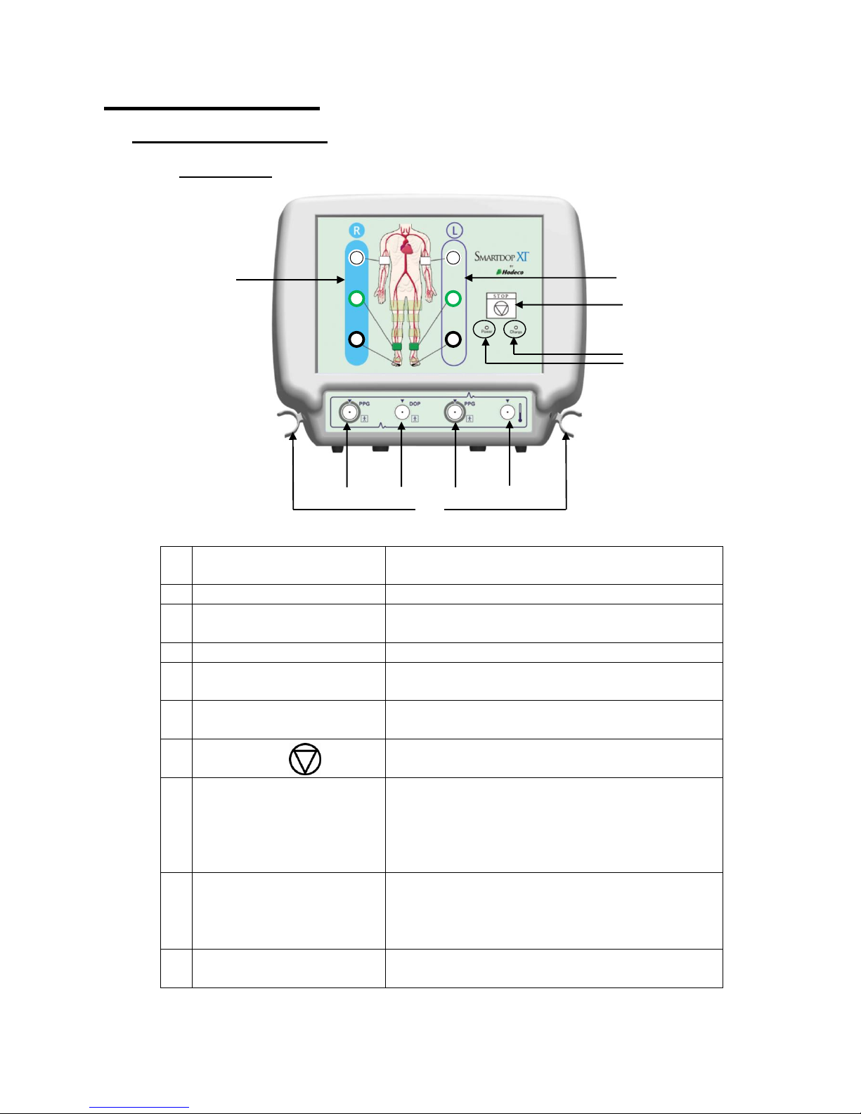
2-1. Smartdop XT
Front view
1
Inflation ports for right
side
To connect extender tubes for right side cuffs
2
Inflation ports for left side
To connect extender tubes for left side cuffs
3
PPG probe connector
for right side
To connect right PPG probe
4
Doppler probe connector
To connect Doppler probe, option
5
PPG probe connector
for left side
To connect left PPG probe
6
Foot temperature probe
connector
To connect foot temperature probe, option
7
Stop button
To stop testing and dump all cuffs immediately
while in measurement
8
Charge indicator
To indicate battery charging status as follows;
Orange LED: Charging battery with AC
adaptor
LED turns off: When battery fully charged
(See “§3-1. Charging battery” for details.)
9
Power indicator
To indicate the power status as follows;
Green LED: Unit turned on
Green LED blinking: Low battery
LED turned off: Unit turned off
10
Probe holder
To place optional Doppler/ temperature probe
when not in use
10
1
2
3 4 5
6
7
8
9
Page 9
3
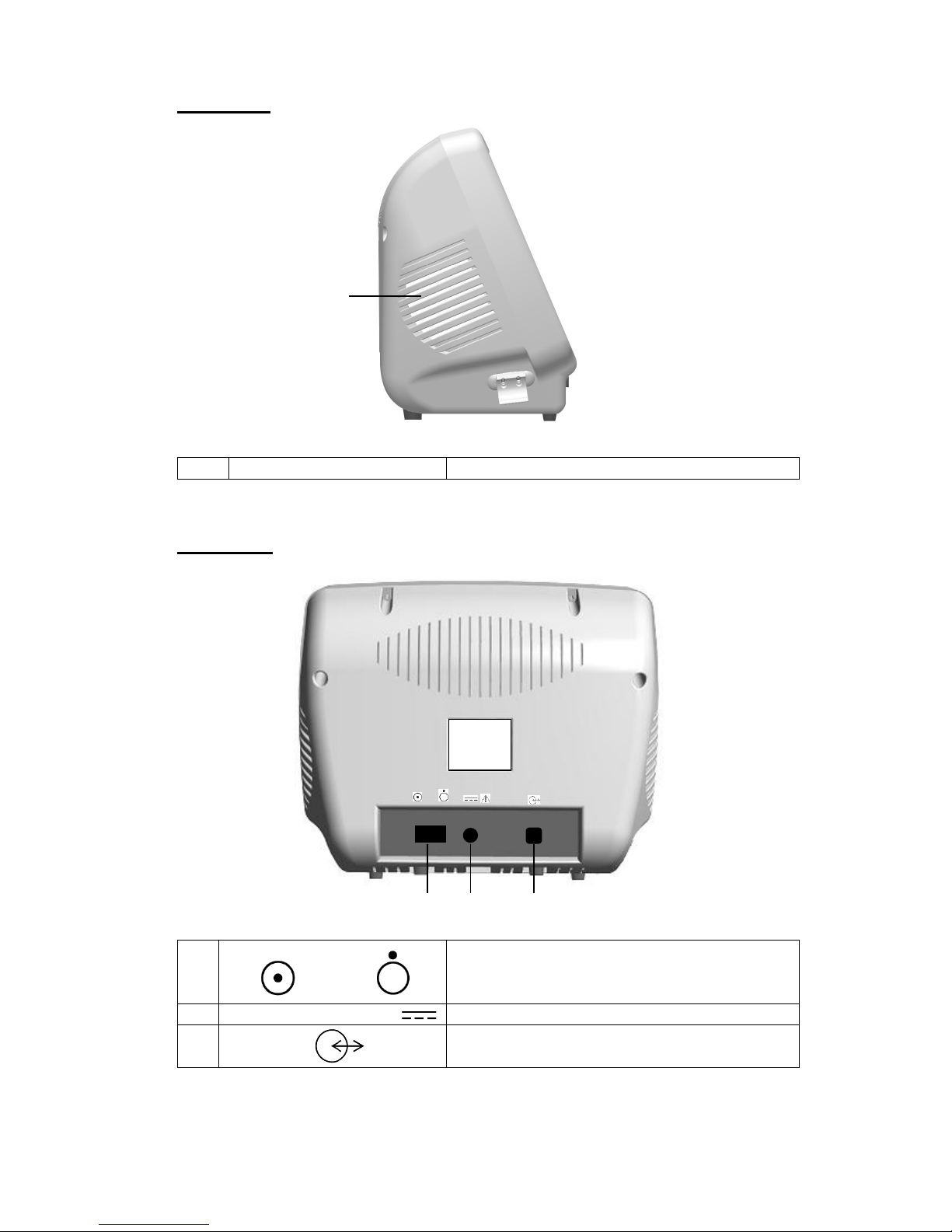
Side view
11
Speaker
To output sounds
Note: Sound volume can be adjusted on each testing screen of Smart-XT-Link software.
Rear view
12
Power switch
ON: OFF:
To turn the unit ON and OFF
13
AC adaptor connector
To connect designated AC adaptor
14
Serial port
To connect computer with designated USB
cable
11.
12
13
14
SmartdopXT
Page 10

4
2-2. Probes
PPG probe
Model: PG-01
Doppler probe (Option)
Model: BT*M05S8C (A) *Frequency
Temperature probe (Option)
Model: TP-01
15
PPG transducer
To detect toe PPG waveforms for toe and
transmetatarsal pressures
16
Doppler probe button
To freeze and unfreeze the waveform
17
Doppler transducer
To detect blood velocity
18
Probe cap
To protect the transducer tip when not in use
19
Temperature probe button
To record the foot temperature
20
Temperature transducer
To detect foot temperature
19
20
16
17
18
15
Page 11
5
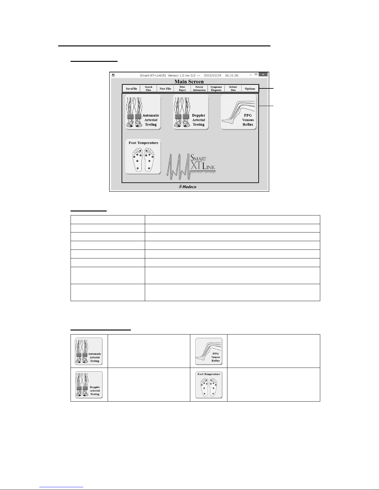
2-3. Smart-XT-Link for 6 ports for Windows
Main screen
Menu bar
Save File
To save data file
Search Files
To search data files to open
New File
To create new patient file
Print Report
To print report or export it to PDF file
Patient Information
To input patient data
Symptoms/Diagnosis
To input symptoms and diagnosis for patient
Default Data
To input and/or revise Default Data: Facility data,
Performing Studies and Requesting Physician
Options
To set optional settings for CommPort, Language,
DICOM®, data folder and others
Launcher icons
Automatic Arterial
Testing
PPG Venous Reflux
Doppler Arterial Testing
Foot Temperature
Menu bar
Launcher icons
Page 12

6
3. Getting started
3-1. Charging battery
(1) Turn the unit off and plug the AC adaptor to it to charge the battery.
The Charge indicator will turn to orange while charging is in progress.
(2) When the battery is fully charged, the orange Charge indicator will be turned off.
Unplug the AC adaptor.
Note: When the battery is low, the green Power indicator blinks. Use the designated AC
adaptor for charging.
3-2. Software installation
3-2-1. Installing Smart-XT-Link
(1) Insert the Smart-XT-Link for 6 ports CD-ROM into the drive of your
computer.
(2) Installer dialog box will appear automatically, otherwise open My Computer
and double-click the CD-ROM drive in which Smart-XT-Link CD is inserted,
and double-click Setup.exe to install Smart-XT-Link software. Follow the
instructions of the installer.
(3) When installation process is completed, Smart-XT-Link will start
automatically with Default Data screen.
3-2-2. Installing USB Cable Driver
(1) Set the Smart-XT-Link for 6 ports V1.0 CD-ROM on your CD-ROM drive.
(2) If automatic installer Smart-XT-Link for 6 ports Ver1.0 installation pops
up, click on Cancel.
(3) Connect the Smartdop XT to your computer by using the USB cable
enclosed.
The following procedures depend on your Windows version as follows:
Windows Vista
(4) When Found New Hardware is shown, click Locate and install driver
software (recommended).
(5) If Found New Hardware - Unknown Device is shown, click Don't search
online.
(6) Windows Security Window alerts you that the publisher of the driver cannot
be verified. Click Install this driver software anyway.
(7) The USB cable driver will be installed.
(8) When completion dialog is shown, click Close.
(9) If another "Found New Hardware" pops up after completing up to step #8,
repeat step #4 to 8. After the end of work, set the COM port of
Smart-XT-Link. (Refer to the section "§5-8. Options".)
Page 13

7
Windows 7 and 8.1
(4) A shortcut for "Windows 7 and 8 Driver Installation" will be created
automatically on the desktop when Smart-XT-Link installation is completed.
Click it and follow the instructions.
3-2-3. Uninstalling Smart-XT-Link
(1) Before uninstalling Smart-XT-Link, copy all the waveform data saved on the
WaveData folder for future reference.
The initial WaveData is located in C: \Hadeco \SXTLink6_1.0\. (Default)
(2) Select Hadeco\Smart-XT-Link6 Ver1.0\Uninstall Smart-XT-Link6 Ver1.
on Program menu to uninstall Smart-XT-Link.
Note: Smart-XT-Link does not support both Windows power options of Sleep and
Suspend and thus disable the options while using the software.
Page 14
8
4. Testing
4-1. Starting operation
(1) Connect the USB cable to the unit.
Caution: Use the designated USB cable, Model #: USB-CB5.
(2) Connect the other side of the cable to USB port of the computer.
(3) Turn the unit on.
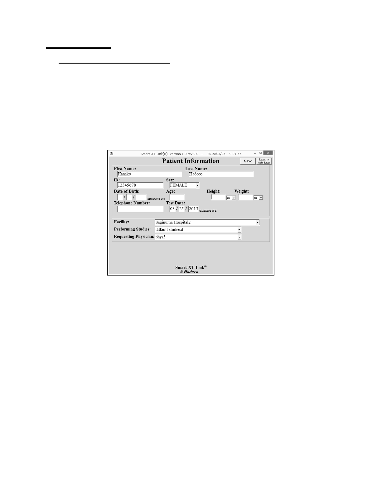
(4) Start Smart-XT-Link and Patient Information screen will appear.
(5) Type the patient information or you may do it later.
(6) Click Save to save the information and it will go to Main Screen.
(7) Click Options and do Search Comm once to search for COM port where the unit is
connected and Smart-XT-Link will show the COM port #. Do the other settings
desired on Option Screen. (See section “§5-8. Option Screen” for more details.)
(8) Click Return to Main Screen.
Page 15
9
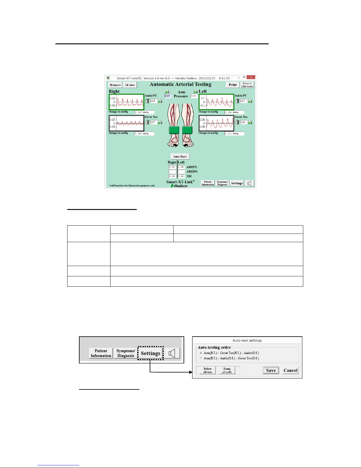
4-2. Automatic Arterial Testing (Oscillometry)
Automatic Arterial Testing includes ABI, TBI and PV-Arterial studies for up to 6 sites
with simple one-button operation. PPG and oscillometry are used for taking blood
pressures on great toes, ankles and Arms, respectively.
4-2-1. Preparations
(1) Get the necessary components ready as the following example for 6 sites:
Cuffs
(Option)
VC-10: 4 pcs.
For brachia and ankles
DVC-1.9: 2 pcs.
For great toes
Tubing
2 tubing each color x 3 sets;
White for Arm, Green for Ankle/PT, Black for Great toe
(Tubing with blue mark at both ends are for the right side)
PPG probe
PG-01 x 2 pcs.
PPG clip
PPG Clip x 2 pcs.
(2) Click Automatic Arterial Testing launcher icon on Main Screen.
(3) Settings
Click Settings button on Automatic Arterial Testing screen and set the
Auto-testing order as follows.
Auto-testing order:
No.1: Arm (R/L) - Great Toe (R/L) - Ankle (R/L)
No.2: Arm (R/L) - Ankle (R/L) - Great Toe (R/L)
Default setting is No.1.
Click Save to set the settings.
<Automatic Arterial Testing screen>
Page 16
10
Delete all data:
Click Delete all data to delete all waveform data on the screen.
Dump all cuffs:
Click Dump all cuffs to dump all cuff.
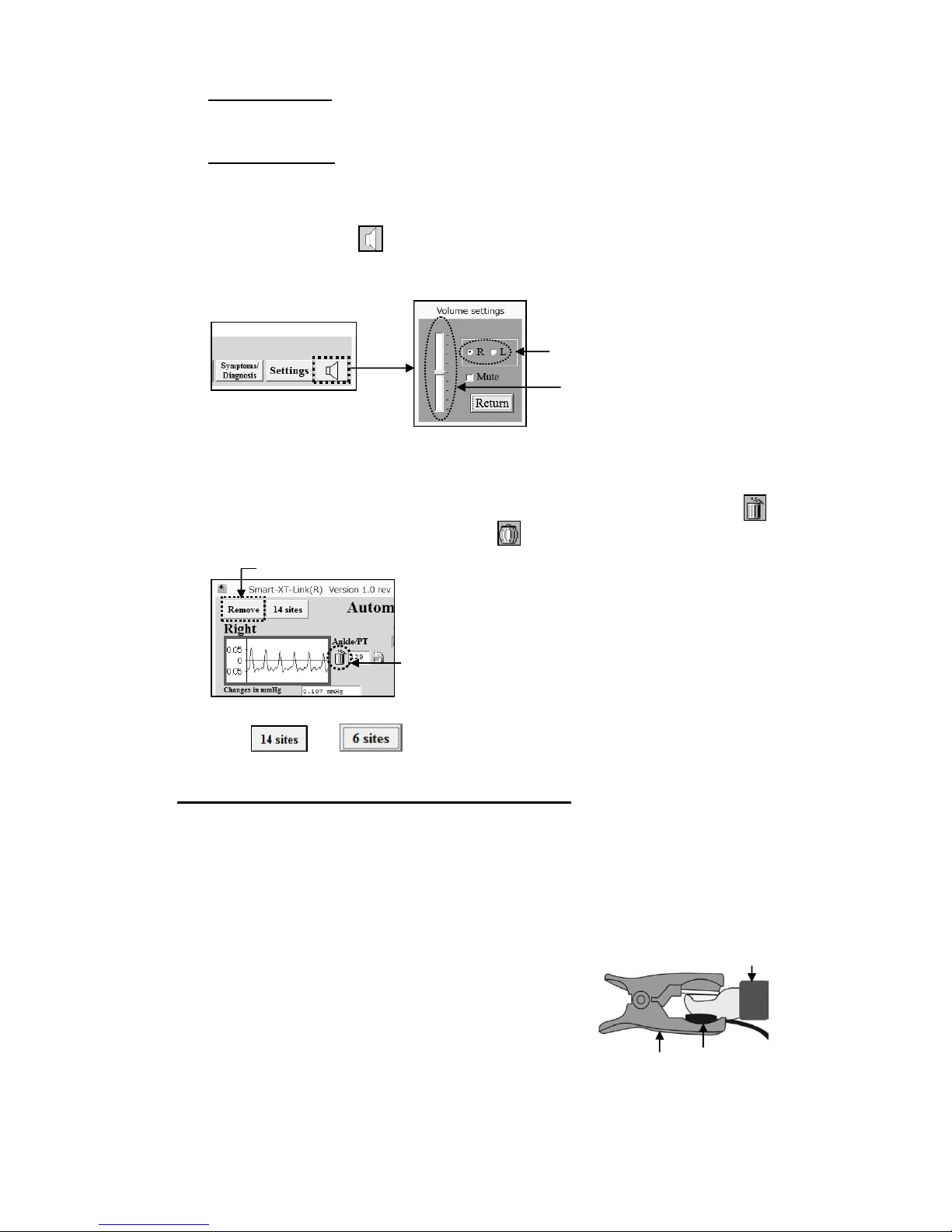
(4) Sound adjustment
Click Sound button and select R or L side from where PV waveform sounds
come out from the speaker and move the slider to adjust the sound volume.
Check the Mute check box to mute the sound volume.
Note: No sounds during oscillometry testing.
(5) Removing waveform window(s)
To remove waveform window(s) you do not use, click each trash can next to
the window, clicked can becomes fat , and then click Remove button to
proceed.
Click & buttons to get the removed window(s) back.
4-2-2. Starting Automatic Arterial Testing
(1) Wrap cuffs snugly on each side of brachium, ankle, and great toe.
Note: Use appropriately sized cuffs for each patient.
(2) Hook up each color coded tubing between cuff and the inflation port with the
same color as tubing’s for each site.
(3) Connect 2 PPG probes to the unit and affix
each PPG transducer with clear side
against the pad of each great toe with PPG
probe clip.
Note: PPG probe is used for taking great toe pressures.
(4) Click Auto Start button and auto-testing will start on both sides simultaneously
in the order selected in Auto-testing order.
Select R or L.
Slider
Trash can
Remove button
Clip
PPG probe
Toe cuff
Page 17
11
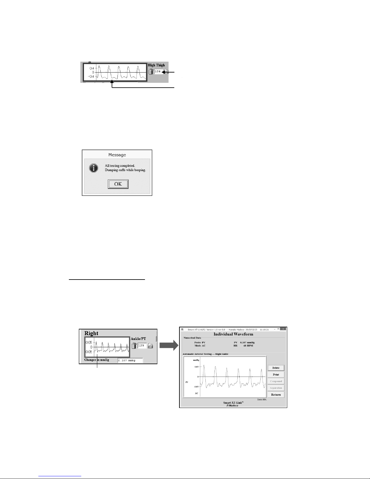
When each testing is completed, the blood pressure value and pulse volume
(PV) waveform will be shown in blood pressure box and waveform window,
respectively, as shown below.
Note: Auto start button will change to Stop button while in testing. Click Stop button to
stop the testing.
Note: For legs, PV testing is performed prior to each blood pressure testing.
(5) When all tests are completed, the dialog box as shown below will appear.
Click OK to close it and ABI and TBI will be calculated automatically during the
tests. After all testing is completed, Smartdop will dump all cuffs with beeping
automatically.
Note: ABI = (Ankle pressure) / (Brachial pressure)
TBI = (Toe pressure) / (Brachial pressure)
Enlarging waveform
Right click one of PV waveform windows to enlarge it and the Individual waveform
screen will appear for waveform analysis.
Click Delete to delete the waveform.
Click Print to print out the waveform data.
Click Return to go back to previous screen.
Blood pressure
Pulse volume (PV) waveform
Right click here.
Page 18
12
Manual testing
Each site can be manually tested as follows:
Manual testing of PV waveform:
(1) Click the PV waveform window where you wish to test manually and Smartdop
will start PV testing.
Manual testing of blood pressure testing:
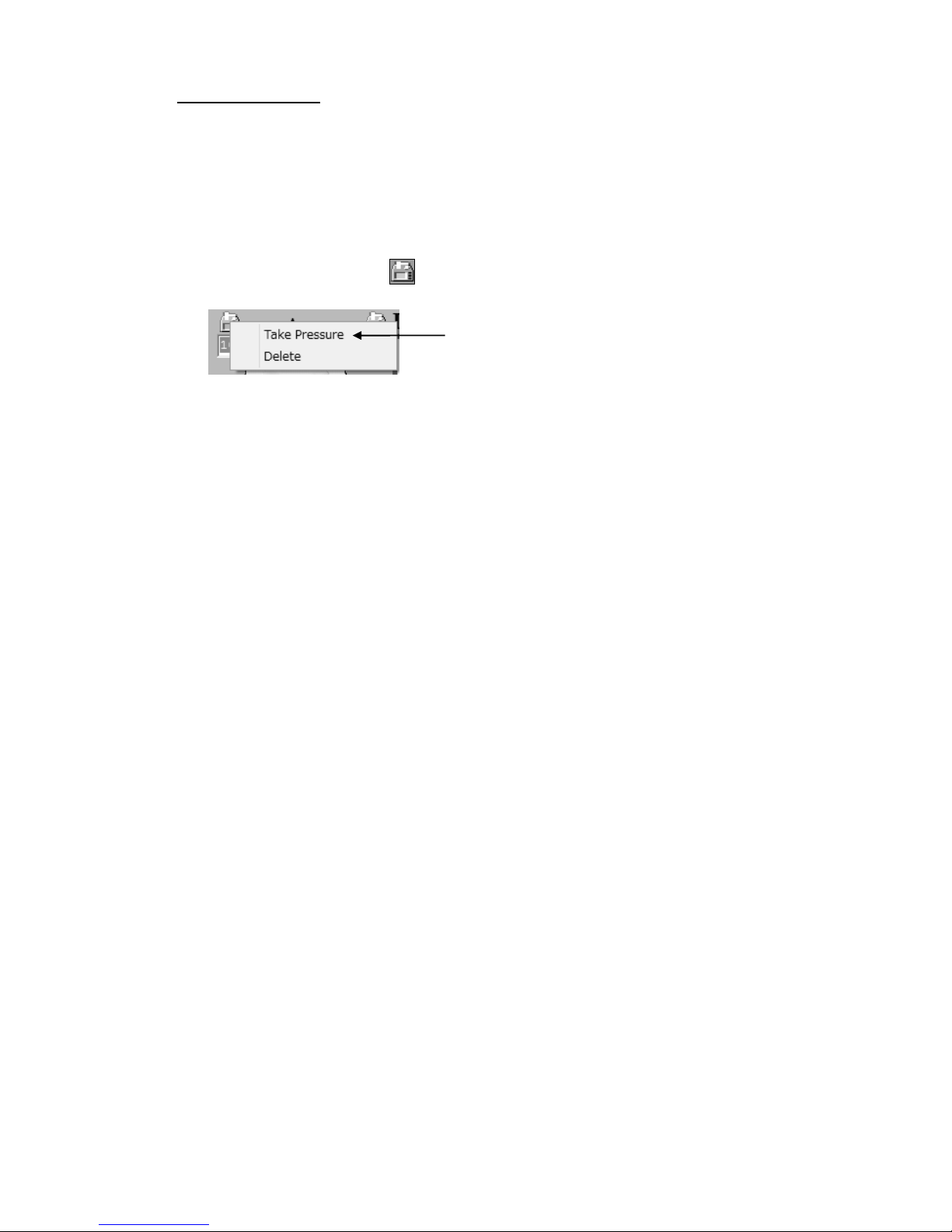
(1) Click the pressure icon where you wish to test manually.
(2) Select Take pressure in pull-down menu to start testing.
Select Take pressure
Page 19
13
4-3. Further segmental studies
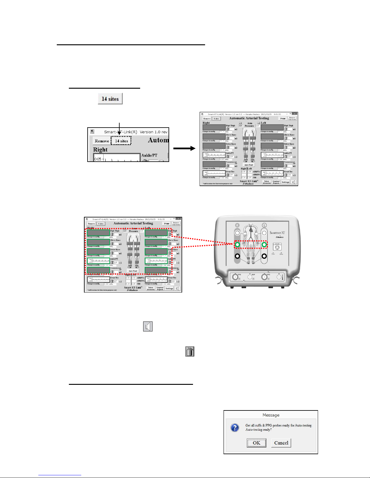
If desired, further blood pressure segmental studies can be performed with the Smartdop
on rolling basis operation for up to 14 sites on both Automatic Arterial Testing and
Doppler Arterial Testing screens.
4-3-1. Preparations
(1) Click button on the testing screen to show 14 each of blood pressure
box and waveform window.
Note: The green inflation ports for ankles will be used for the segmental testing at high thigh,
above knee, below knee, and transmetatarsal/DP as well as ankle/PT.
(2) Click Settings button and set the Auto-testing order and click Save to set the
settings.
(3) Sound adjustment
See the step# (7) in the “§4-2-1. Preparations” for sound adjustment.
(4) Removing waveform window(s)
See the step# (8) in the “§4-2-1. Preparations” for removing the window(s).
4-3-2. Starting segmental studies
(1) Wrap cuffs, tubing and PPG probes ready
for the testing sites.
(2) Click Auto Start button to start auto-testing
and follow the guidance to proceed.
14 sites button
Page 20
14
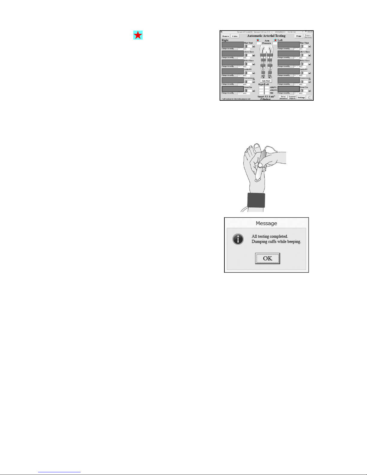
Red star mark(s) appears to let you
know for which site(s) you should get the
cuff(s) ready.
Note: PPG probe must be used for taking great toe and transmetatarsal pressures.
Note: Auto start button changes to Stop button while in testing. Click Stop button to stop
the testing.
Note: On Doppler Arterial Testing, ankle cuff is used
for taking transmetatarsal/DP pressure as shown
in the right.
(3) When all tests are completed, the dialog
box as shown right will appear. Click OK to
close it.
Smartdop will dump all cuffs automatically
while beeping.
Page 21
15
4-4. Doppler Arterial Testing
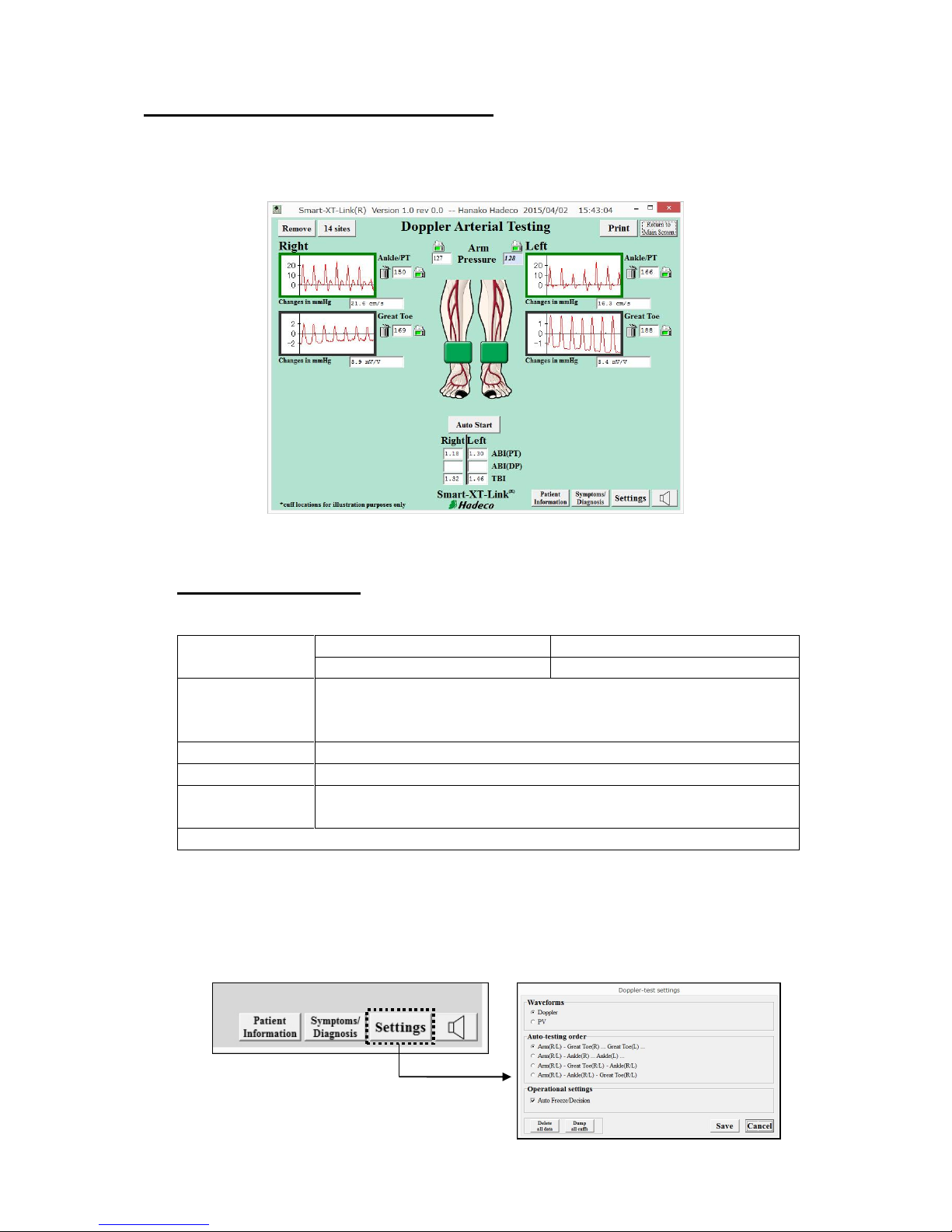
Doppler Arterial Testing includes ABI, TBI and PV-Arterial studies for up to 6 sites
with semi-automatic simple operation. PPG and Doppler probes are used for taking
blood pressures on great toes, ankles and Arms, respectively.
4-4-1. Preparations
(1) Get the necessary components ready as the following example for 6 sites:
Cuffs (Option)
VC-10: 4 pcs.
For brachia and ankles
DVC-1.9: 2 pcs.
For great toes
Tubing
2 tubing each color x 3 sets;
White for Arm, Green for Ankle/PT, Black for Great toe
(Tubing with blue mark at both ends are for the right side)
PPG probe
PG-01 x 2 pcs.
PPG clip
PPG Clip x 2 pcs.
Doppler probe
(Option)
BT8M05S8C x 1pc.
Ultrasonic gel (TSUBAKIYA) for Doppler testing (Option)
(2) Click Doppler Arterial Testing launcher icon on Main Screen.
(3) Settings
Click Settings button on Doppler Arterial Testing screen and set Doppler-test
settings as follows.
<Doppler Arterial Testing screen>
Page 22
16
Waveforms:
Select Doppler or PV which is used for waveform testing.
Auto-testing order:
Select the Auto-testing order desired from following 4 orders:
Default setting differs depending on which Doppler or PV is used for waveform testing as follows;
When Doppler is used for waveform testing: No.1
When PV is used for waveform testing: No.3
Operational settings:
Auto Freeze / Decision
Check the check box to freeze the waveform and save the testing data
automatically when waveform becomes stable.
Click Save to set the settings.
Delete all data:
Click Delete all data to delete all waveform data on the screen.
Dump all cuffs;
Click Dump all cuffs to dump all cuffs.
(4) Sound adjustment
See the step# (7) in the “§4-2-1. Preparations” for the details.
(5) Removing waveform window(s)
See the step# (8) in the “§4-2-1. Preparations” for removing the window(s).
4-4-2. Starting Doppler Arterial Testing
(1) Wrap cuffs snugly on each site of brachium, ankle and great toe.
Note: Use appropriately sized cuffs for each patient.
(2) Hook up each color coded tubing between cuff and the inflation port with the
same color as tubing’s for each site.
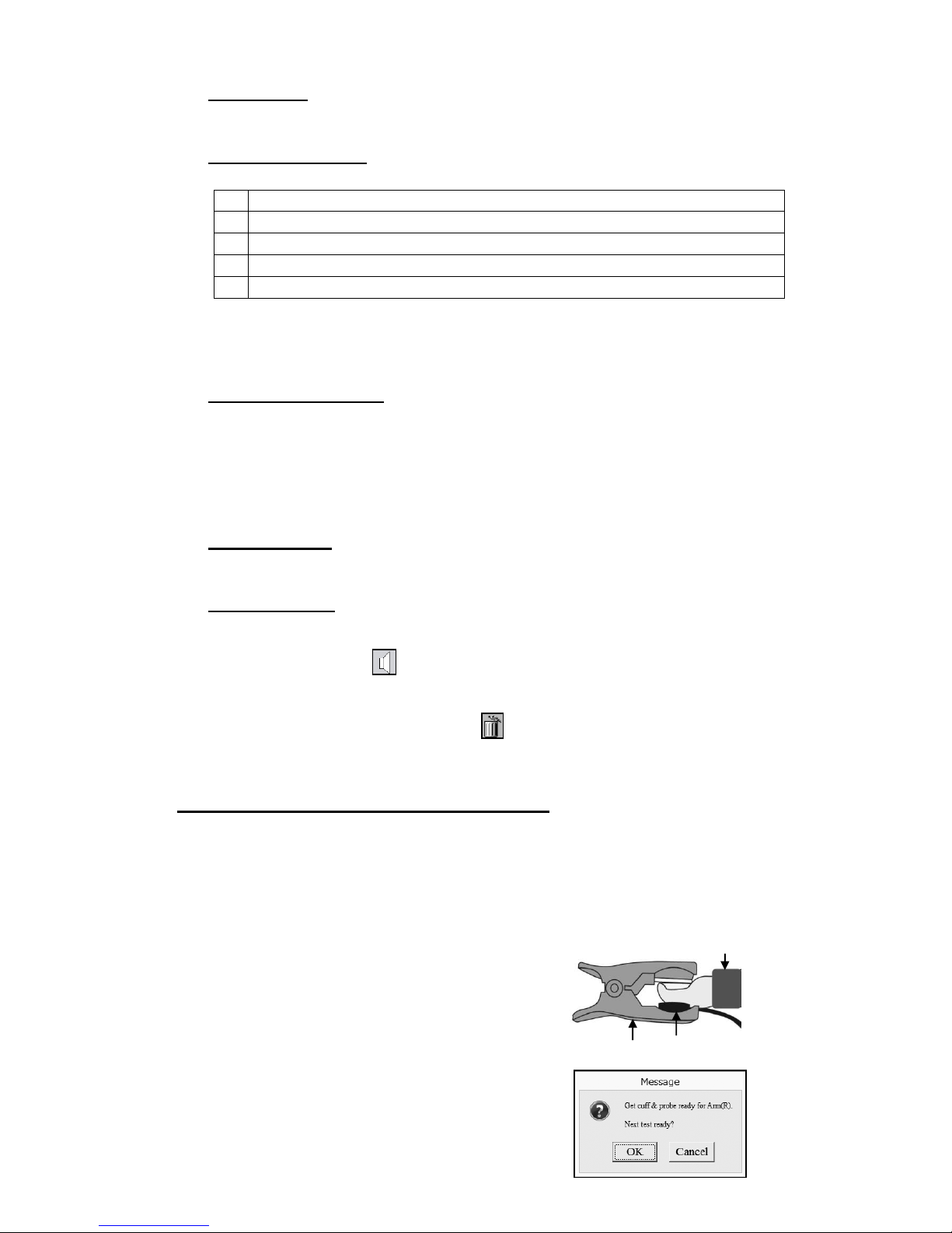
(3) Connect 1 Doppler and 2 PPG probes to the
unit and affix each PPG transducer with
clear side against the pad of each great toe
with PPG probe clip.
(4) Click Auto Start button to start Auto-testing
and dialog box as shown in the right will
appear.
No
Auto-testing order for Doppler Arterial Testing
1
Arm (R/L) – Great toe (R) - Ankle/PT (R) - Great toe (L) - Ankle/PT (L)
2
Arm (R/L) - Ankle/PT (R) - Great toe (R) - Ankle/PT (L) - Great toe (L)
3
Arm (R/L) - Great Toe (R/L) – Ankle/PT (R/L)
4
Arm (R/L) - Ankle/PT (R/L) – Great Toe (R/L)
PPG probe
Toe cuff
Clip
Page 23
17
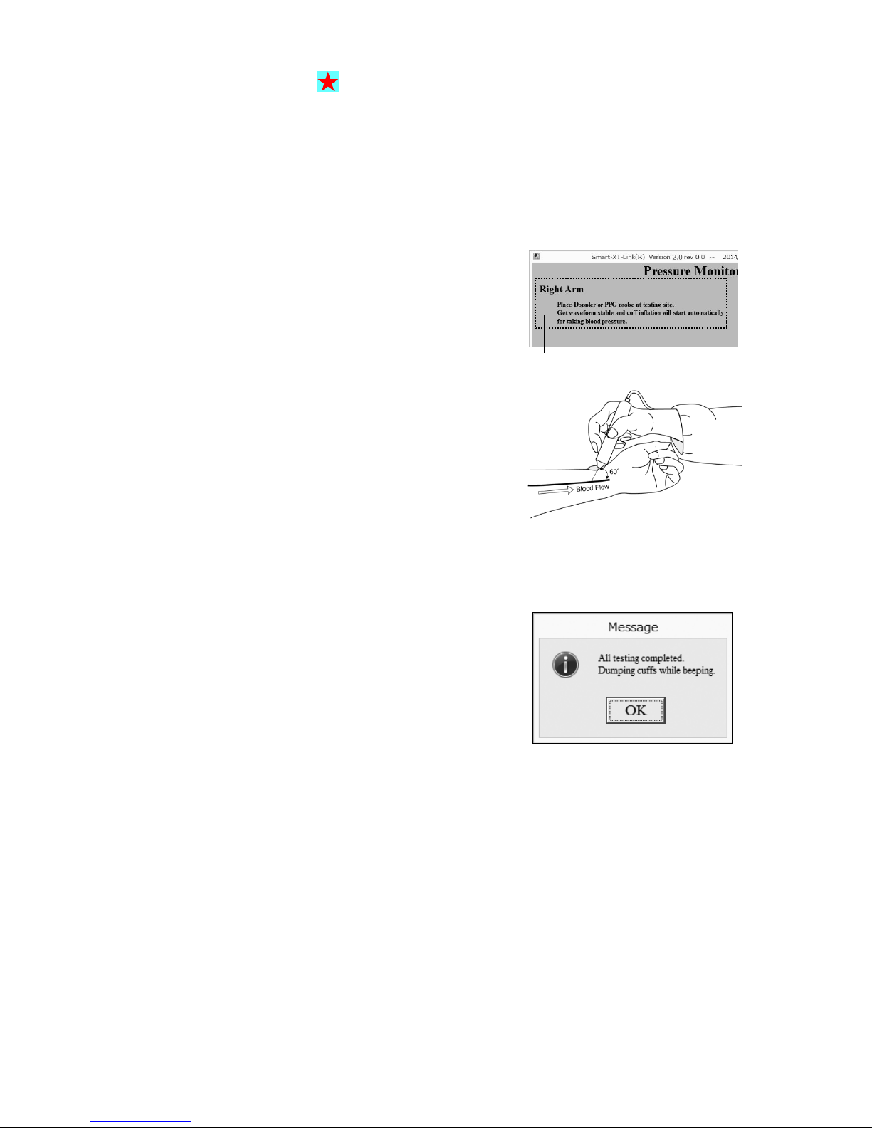
Red star mark(s) appears to let you
know for which site(s) you should get the
cuff(s) ready.
(5) Click OK or hit Space bar to start auto-testing.
Note: Auto start button changes to Stop button while in testing. Click Stop button to stop
the testing.
(6) When taking blood pressures except great
toe, follow the guidance with site name
shown on upper left of monitoring screen to
perform the testing.
Note: All the PV testing is performed prior to
blood pressure testing.
Note: For Doppler testing, put ultrasonic gel on tip
of Doppler probe. Place the probe to the
artery with an angle of 45 to 60 degrees and
move it slowly to locate the point where the
maximum sounds are heard. Adjust sound
volume if necessary.
Note: Smartdop always restart Auto-testing by
re-clicking Auto Start from where any
testing has been cancelled.
(7) When all tests are completed on Doppler
Arterial Testing screen, the dialog box as
shown right will appear. Click OK to close it
and ABI and TBI will be calculated
automatically during tests.
After all testing is completed, Smartdop
will dump all cuffs automatically while
beeping.
Note: ABI = (Ankle pressure) / (Brachial pressure)
TBI = (Toe pressure) / (Brachial pressure)
Guidance
Page 24
18
Enlarging waveform
PV/ blood velocity waveforms: Right click one of waveform windows. See “Enlarging
waveform” of “§4-2-2. Starting Automatic Arterial
Testing”.
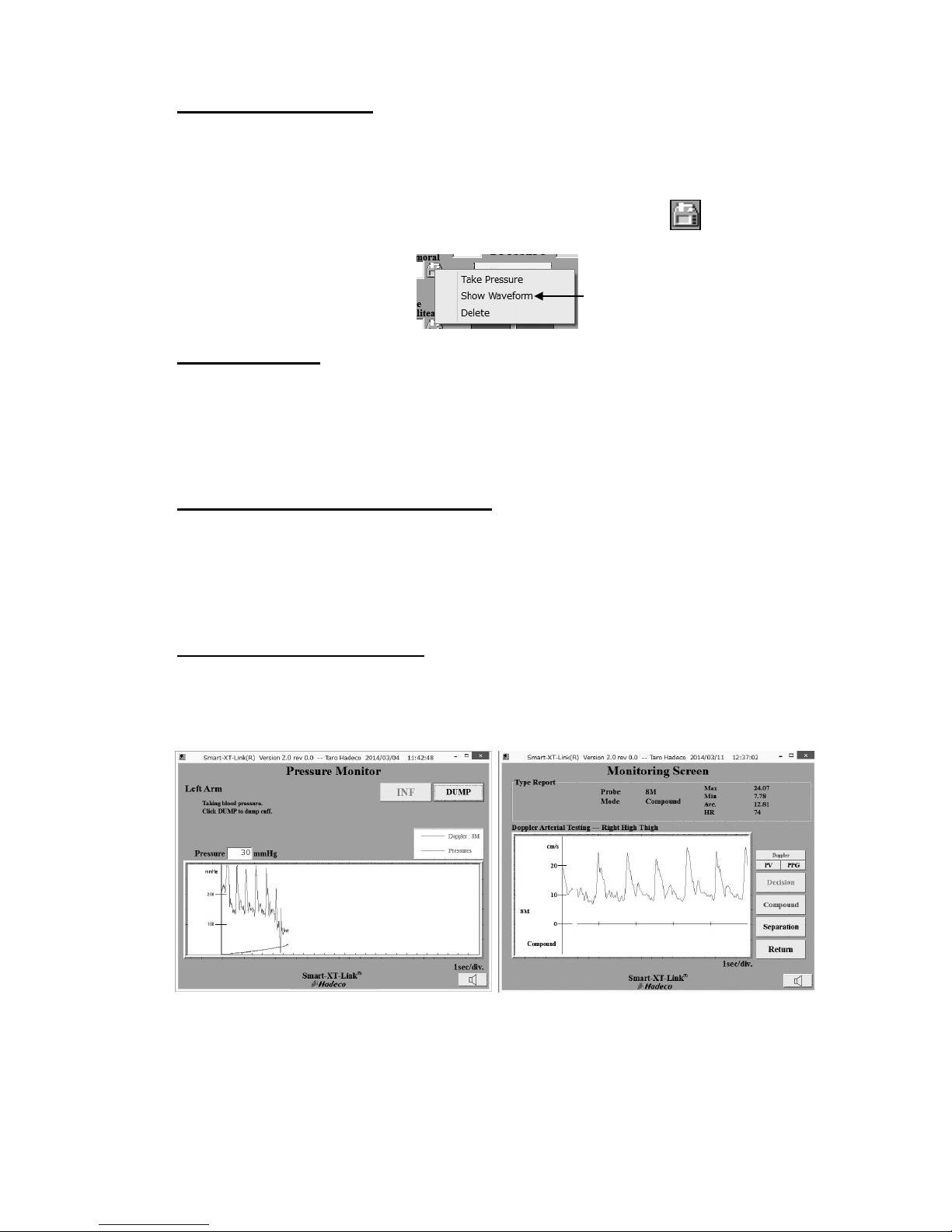
Blood pressure waveforms: Right click one of pressure icons and click Show
Waveform to enlarge the waveform.
Manual testing
Each site can be manually tested in the same manner as other testing.
See “Manual testing” in the “§4-2-2. Starting Automatic Arterial Testing” for
more details.
4-4-3. Further segmental studies
If desired, further blood pressure segmental studies can be performed with the
Smartdop on rolling basis operation for up to 14 sites on both Automatic Arterial
Testing and Doppler Arterial Testing screens.
See “§4-3. Further segmental studies” for Automatic Arterial Testing.
4-4-4. Monitoring screen
Each of monitoring screens will show up while performing Doppler blood
pressure testing or individual waveform testing of blood velocity, PV and PPG
on Doppler Arterial Testing screen as follows:
Click Show Waveform
<Pressure Monitor for Doppler>
<Velocity, PV, and PPG waveforms>
Page 25
19
4-5. PPG Venous Reflux
PPG Venous reflux study is performed to assess valvular competence by
measuring the time required for venous refilling after calf veins have been emptied
through exercise.
4-5-1. Preparations
(1) Prepare the following components;
PPG probe: PG-01 x 2 pcs.
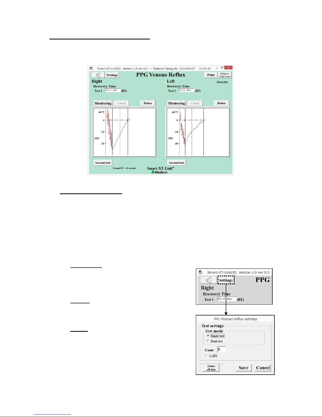
(2) Click PPG Venous Reflux launcher icon on main screen to go to PPG Venous
Reflux screen.
(3) Click Settings button on the screen and set
PPG Venous Reflux settings as follows.
Test mode:
Select either “Single test” or “Dual test” for
testing right and left legs separately or
simultaneously, respectively.
Count:
Type the number of times for patient
dorsiflexes.
1/2RT:
Check the checkbox to show the 1/2RT half
recovery time values on the screen, returning
to 50% of refilling amplitude where vertical
dotted line is shown.
Click Save to set all the settings.
Page 26
20
Delete all data:
Click it to delete all waveform data on the screen.
(4) Sound adjustment
See the step# (7) in the “§4-2-1. Preparations” for sound adjustment.
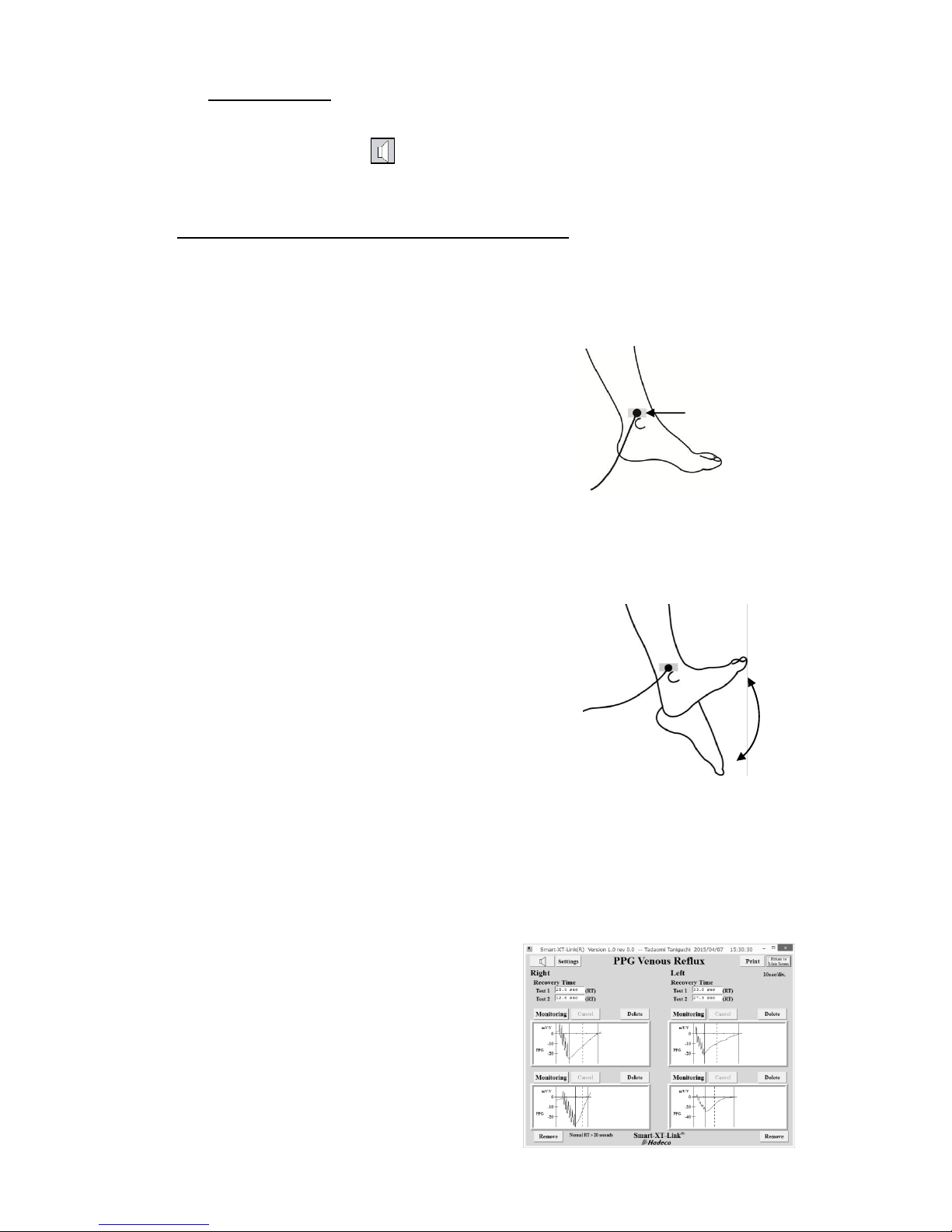
4-5-2. Starting PPG Venous Reflux study
(1) Connect 2 PPG probes to the unit.
(2) Have the patient sit on an examination
table so that feet are off floor.
(3) Apply the PPG transducer with the clear
side against the skin surface to the medal
malleolus over the posterior tibial vein. Fix
the PPG transducer in place with tape.
(4) Click one of Monitoring buttons or
waveform windows to start monitoring the
waveform.
(5) When patient is ready, click Start Test
button to start venous reflux study.
(6) Ask patient to flex his foot synchronizing
with beep sound as many as count number
being set on the settings.
Click Cancel to cancel testing if necessary.
When an appropriate waveform returns to
the base-line amplitude, it will
automatically freeze and save the
waveform and show Recovery Time.
(7) Repeat steps # (4) to (5) on the other side
or on the second test.
Note: Beep sound is heard from the speaker of computer.
Note: Click Second test to add second test
window(s) on the screen if necessary.
Fix PPG transducer
with tape.
Page 27
21
4-6. Foot Temperature
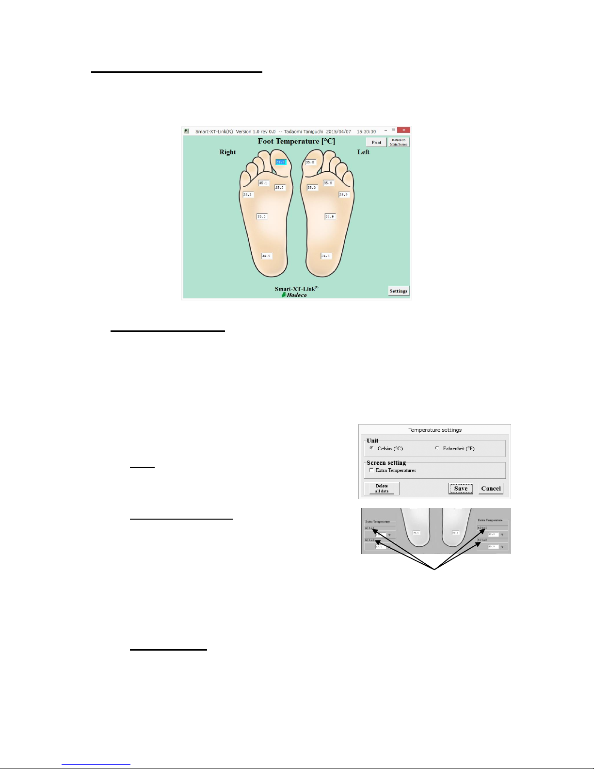
This screen is to record several temperatures on each foot through temperature
probe as well as typing in manually through keyboard. Extra temperature boxes are
available for other sites.
4-6-1. Preparations
(1) Prepare 1 temperature probe, optional, for
foot temperature testing.
(2) Click Foot Temperature launcher icon on
Main Screen.
(3) Click Settings button on Foot Temperature
screen and set the settings as follows.
Unit:
Select either Celsius (°C) or Fahrenheit (°F)
for temperature unit.
Extra temperatures:
Check the checkbox to show extra
temperature boxes on the screen.
Note: Site name for each extra temperature box can
be changed by typing in.
Click Save to set all the settings.
Delete all data:
Click it to delete all temperature data on the screen.
Type the site name here.
Page 28
22
4-6-2. Operation
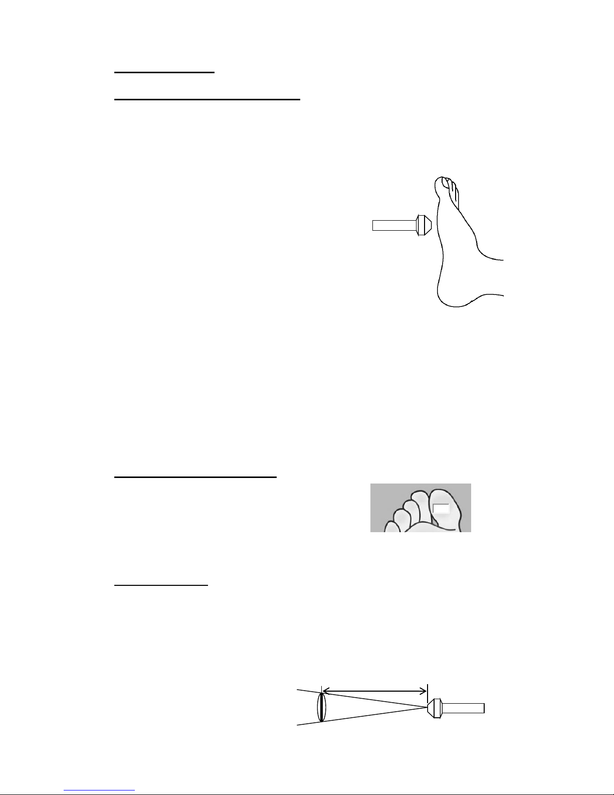
Measuring foot temperatures:
(1) Connect temperature probe, optional, to
the unit
(2) Go to Foot Temperature screen and
temperature box for right toe will be
selected and turn to light blue
automatically.
(3) Get the probe tip close to the measuring
site less than 4 cm as shown in the right.
(4) Press the probe button to measure and
show the temperature in the box and it will
automatically go to the next temperature
box turning into light blue.
Note: Hit space bar or Enter to skip to the next box
without taking temperature OR click the box
where you wish to measure for.
(5) Repeat steps # (3) to (4) for the next site
until all testing is completed.
Note: After using temperature probe, wipe the probe using with a soft dry cloth.
Take great care that any water may not penetrate into the probe.
Typing foot temperatures:
(1) Click the temperature box where you wish
to type one in taken by an external
thermometer and it will turn into light blue.
(2) Type the foot temperature in the box and press Enter.
Specifications:
Temperature measuring method: non-contact
Accuracy: ± 0.5°C (measurement range 10 to 40 °C),
when operating temperature is 0 to 40°C
Display Resolution: 0.1°C
FOV: 4:1 (object distance: measuring range)
Emissivity: 0.98
Object 1cm
Less than 4cm
35.1
Page 29
23
5. Menu
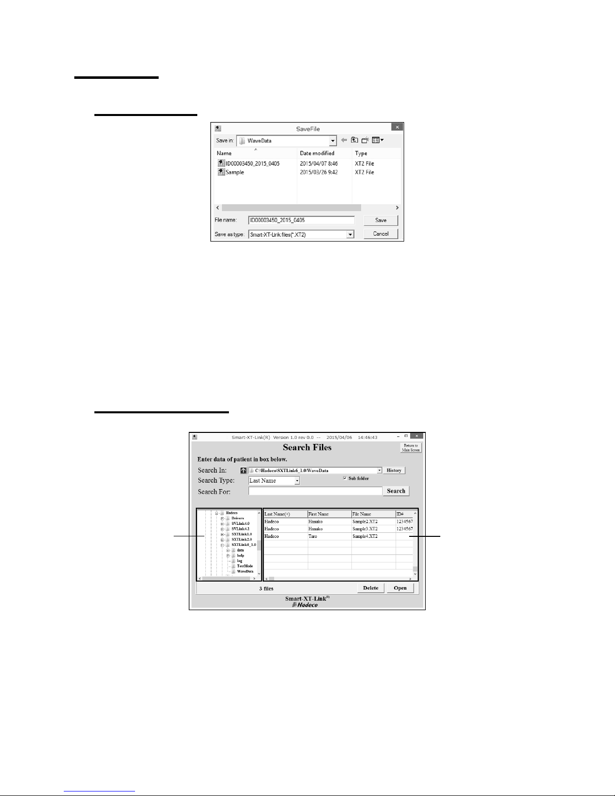
5-1. SaveFile
(1) Click SaveFile on Main Screen to open SaveFile window with a file name of Patient
ID, or name if ID is not typed, along with extension "XT2".
Note: Default data folder can be specified on Option Screen.
(2) Change the file name if necessary and click Save to save testing data.
Note: If the check box of Export to DICOM on Option Screen is being checked, Smart-XT-Link
will automatically export all the report images of each test module to DICOM.
5-2. Search Files
(1) Click Search Files on Main Screen to open Search Files screen and it will show
Smart-XT-Link data files stored on the data folder specified on Option Screen.
(Default: C\Hadeco\SXTLink6_1.0\WaveData)
(2) Select the file you wish to open and double-click on it or click Open to proceed.
Folders pane
Files pane
Page 30
24
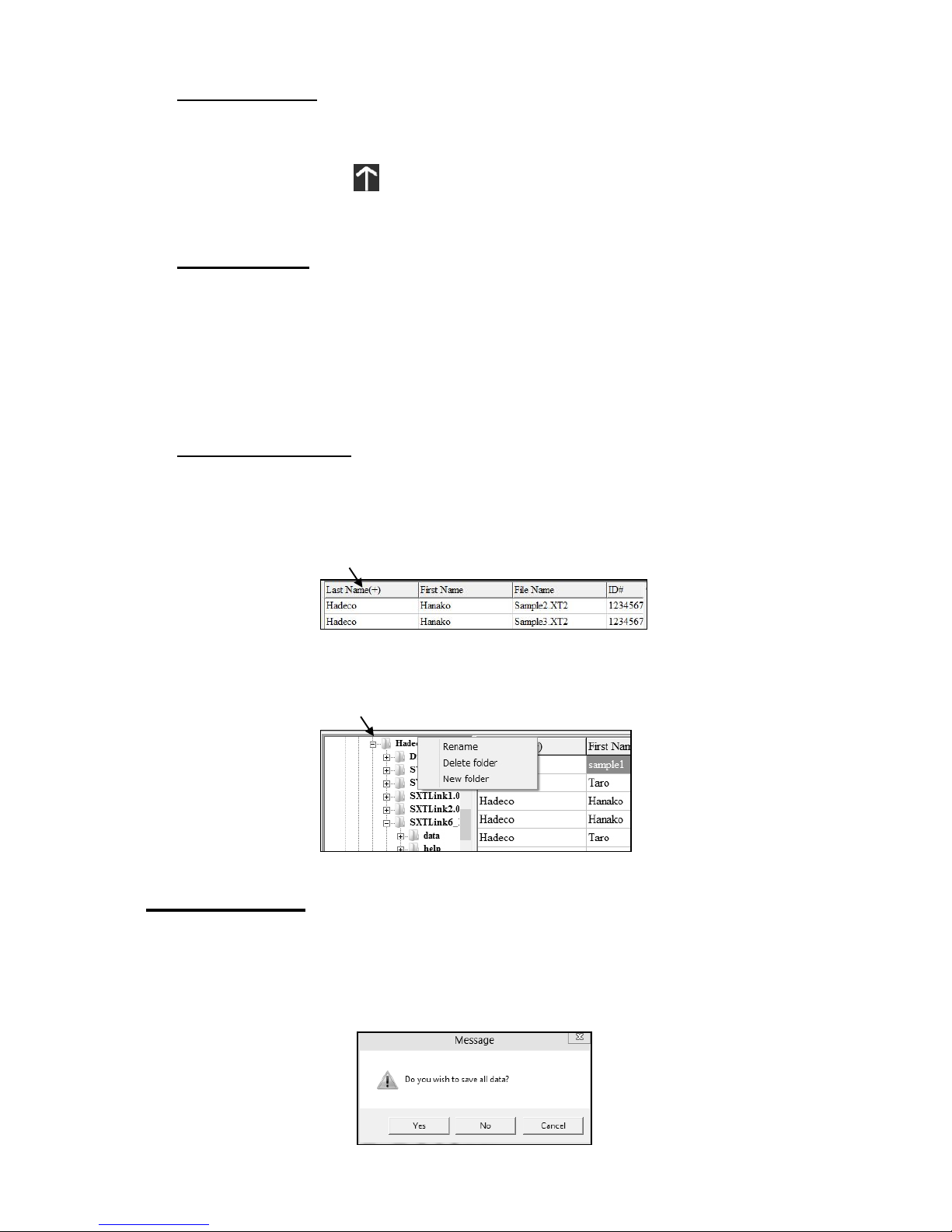
Folder selection:
(a) Click other folder on folders pane where you wish to search files and the
folder path and Smart-XT-Link files found will be shown on “Search In"
path box and files pane, respectively.
(b) Click the up arrow to go to upper folder.
(c) Check Sub folder check box to include sub folders for searching.
(d) Click History to show a list of folder paths you have searched before.
Search options:
(a) Select Search Type from pull-down menu, and type a search word in the
Search For text box.
Note: Search Type includes patient name, ID, file name, requesting physician, and
test date.
(b) Select a file you wish to delete and click Delete to proceed.
Advanced operation:
(a) Folders pane and files pane can be resized by dragging the splitter bar
between the 2 panes. Columns in files pane can also be resized.
(b) Click the column name to sort files alphabetically and click it the second
time to sort anti-alphabetically.
(c) Right-click on folder in folders pane to show a context menu of Rename,
Delete folder and New folder and select the one you wish to proceed.
5-3. New File
Click New File to create a new patient file and Patient Information screen will open.
Type all the patient data and click Save to save the information.
If previous data has not been saved when New File is clicked, a confirmation dialog
box as shown below will appear. Click Yes to save the previous data, No to erase it
or Cancel to cancel New File process.
Click here
Right click here
Page 31
25
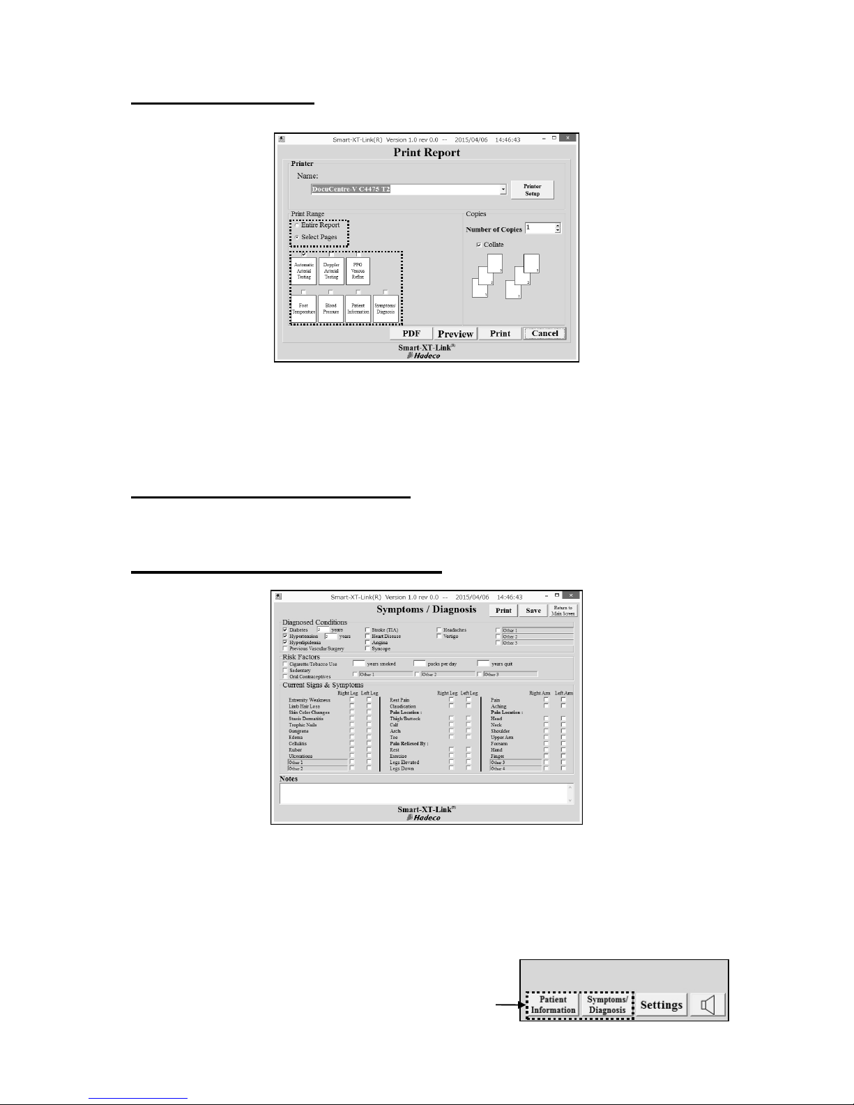
5-4. Print Report
(1) Click Print Report on Main Screen to open the Print Report screen.
(2) Choose the printer and check each check box of the reports you wish to print
out. Select Entire Report if you wish to print all the reports.
(3) Click Print to print out report(s), Preview to see print preview, or PDF to create
PDF report file.
5-5. Patient Information*¹
See the section “§4-1. Starting operation”.
5-6. Symptoms/ Diagnosis*¹
(1) Check the appropriate check boxes and type information in text boxes and then
click Save to proceed.
Note: “Other 1” to “Other 3” can be overtyped with your own word for Diagnosed
Conditions if desired.
*1: To open these screens on the testing screen, click
Patient information, Symptoms/ Diagnosis
buttons on bottom of Automatic Arterial Testing and
Doppler Arterial Testing screen.
Page 32
26
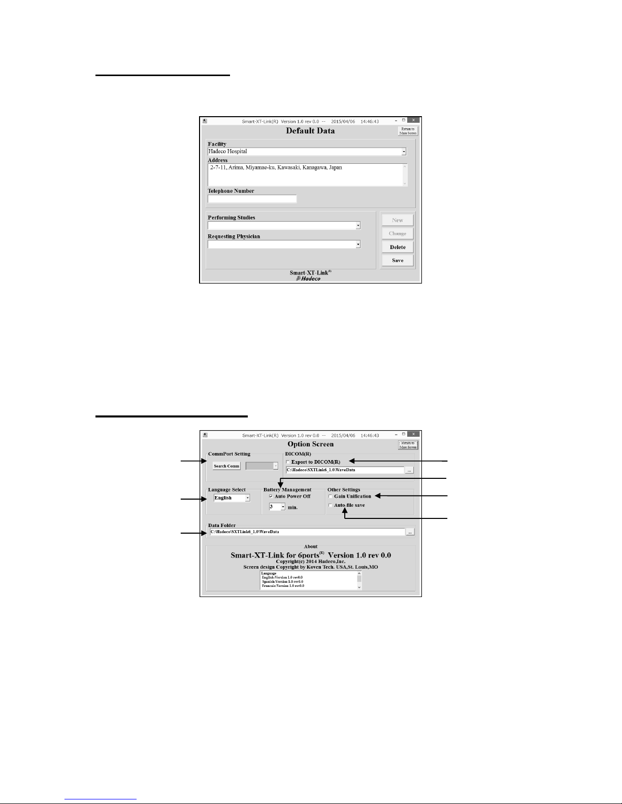
5-7. Default Data
Default data saved on this screen can be used in the pull-down menus on Patient
Information screen.
(1) Type each default data for Facility, Address, Telephone number,
Performing Studies and Requesting Physician.
Select the data and overtype other word and then click Change to revise.
Select the data and click Delete to delete it.
(2) Click Save to proceed when the data have been typed.
5-8. Option Screen
(a) CommPort Setting
Turn on the unit and connect it to computer. Go to Option Screen and click Search
Comm to search COM port connected to the unit. COM port number will be shown
next to Search Comm when it’s been found.
(b) Language Select
Select your language from the pull-down menu and restart Smart-XT-Link to activate
the new language.
(a)
(d)
(f)
(g)
(b)
(c)
(e)
Page 33
27
(c) Data Folder
Click the button "..." and select the folder where you wish to save Smart-XT-Link files
regularly and then click OK. The folder path will be shown in the path box and it will be
used on Search Files and Save File as a default folder.
(d) Export to DICOM
Check it to export the report images to DICOM when data file is saved. Set the
DICOM folder under the check box where DICOM files should be exported.
(e) Auto Power Off
To activate the auto-power-off capability and the unit will be automatically shut off
when it is left on without AC adaptor connected and the auto-off-time selected from
pull-down menu passes. This box is checked as default settings.
(f) Gain Unification
Check it to unify all the amplitude scales of waveforms in each testing module.
(g) Auto-file save
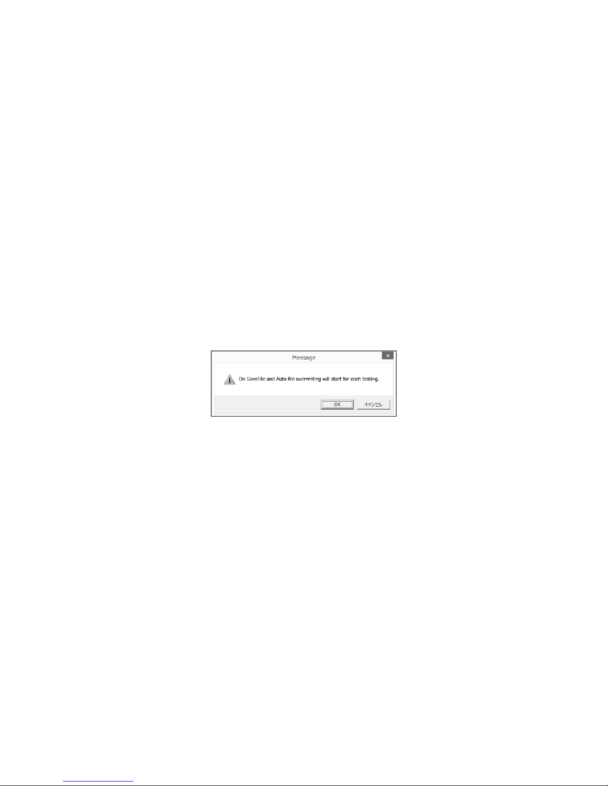
Check it to overwrite the data automatically every time any testing is completed.
A message “Do SaveFile and Auto-file overwriting will start for each testing” will be
displayed as shown below.
Page 34

28
6. Maintenance
6-1.Performance check by user
Perform the following performance checks at least once a year:
(1) Make sure if there is no damage and/or crack on the unit including all
components.
(2) Perform entire tests on either Automatic or Doppler Arterial Testing and make
sure the unit works properly and provides appropriate test results.
Simple check before use:
(1) Connect the unit to your computer and open Smart-XT-Link.
(2) Turn the unit on and make sure the Power LED goes green.
6-2.Cleaning
PROBE
Remove any dust, stain, and gel from the probe.
Clean the probe using damp cloth and then wipe with a soft dry cloth, but take great
care that any water may not penetrate into the probe.
MAIN UNIT
To clean the main unit, use a damp cloth and then wipe with a soft dry cloth, but
take great care that any water may not penetrate into the unit.
CUFFS
The cuffs are intended for use only on intact skin. To clean them, wipe away any dirt
or stain using alcohol.
6-3.Warranty
The guarantee period is two years for the main unit and one year for the probe after
the date of purchase when used under normal conditions. In the event of a problem
during the warranty period, please contact your agent.
In case the warranty period is over, please consult the dealer for a charged service.
Page 35
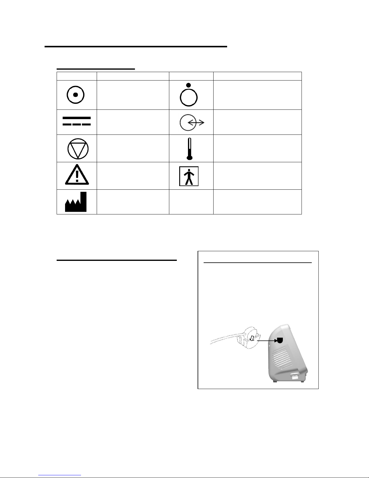
29
7. Supplemental information
7-1. Symbol List
Symbol
Description
Symbol
Description
Power ON
Power OFF
AC adaptor Connector
Serial port
Stop button
Temperature probe connector
Caution*
Type BF
applied part
Manufacturer
* Caution must be observed to avoid damage to the unit. Refer the operating manual carefully.
7-2. Contents of package
Main unit ····································· 1
Smart-XT-Link for 6 ports CD-ROM ·· 1
USB cable (USB-CB5) ··················· 1
Operating manual ························· 1
Tubing ········································ 6
AC adaptor (DPS54-M) ·················· 1
Power cable ································· 1
PPG probe (PG-01) ······················· 2
PPG probe holder ························· 2
PPG probe clip ····························· 2
How to use the PPG probe holder
1. Attach the holder to the flat
place on the main unit with
double-sided tape.
2. Put PPG transducer to the
holder as shown below.
Page 36

30
7-3. Options
Cuffs: Refer the following cuff size as example;
Cuff
Site name
VC-10, VC-12
Brachia, above knees, below knees, ankles
and high thighs
VC-1.9
Great toes
VC-7.5
Transmetatarsi
Probes: Doppler probe: Freq. 4MHz, 5MHz, 8MHz or 10MHz
Temperature probe: Model: TP-01
Ultrasonic gel Manufactured by TSUBAKIYA
8. Technical information
8-1.Principles
Doppler blood velocity measurement:
While performing Doppler waveform test on Doppler Arterial Testing, blood flow
velocity is detected through the ultrasound which is transmitted from probe to patient
body and is reflected by the blood (hemocyte, etc.).
The unit amplifies the high frequency oscillation output and then supplies it to the
transmitter transducer. It is converted to ultrasound by the transducer and the
ultrasound is transmitted to external objects. The ultrasound moves straight through
biophysical object, and is reflected by the moving object (blood flow, fetal heartbeat
etc.).
The reflected ultrasound is received by the receiving transducer and is converted into
electric signals again.
The converted signals are amplified and then detected. After removing unnecessary
noise from the signals and improving S/N ratio at the filter circuit, the Doppler shift
signals are amplified and are converted to audible sounds through a speaker.
Simultaneously, the Doppler shift signals are applied to the CPU and converted to
blood flow velocity waveform signals which can be displayed.
Doppler blood pressure measurement:
While taking blood pressures on Doppler Arterial Testing, the blood pressure cuff is
wrapped where the blood pressure is taken and the probe is put on the arm/leg artery
by the operator.
Before the inflation, the peak amplitudes of the blood flow signals should be stable.
As the cuff pressure goes up by activating the inflation pump, the blood vessel is
being pressed and the peak amplitudes become lower. The CPU finds the point
where the peak amplitudes are below the threshold and waits until the cuff pressure is
inflated an estimated 20 mmHg above the point. Then the CPU deactivates the
inflation pump and lets the cuff pressure go down at a moderate rate until the first
blood flow signal that exceeds the threshold is detected.
Page 37

31
The cuff pressure at the first signal is the systolic pressure. After confirming a return
of the rhythmical blood flow signals, the CPU opens the air valve to dump the cuff
pressure and converted to systolic pressure waveform signals which can be
displayed.
Oscillometry:
While taking blood pressure on Automatic Arterial Testing screen and deflating cuff
for arm or leg after the inflation, the unit detects oscillations of the blood vessel
synchronizing with each heart beat and determines the systolic pressure based on
oscillometry algorithm.
Photoplethysmography:
While taking toe pressure with PPG probe as well as performing PPG venous reflux
study, the unit senses the reflection of light from the hemoglobin of the red blood
cells in surface vessels by utilizing infrared light with the probe.
Pneumoplethysmography (PV):
While performing PV waveform test for toes and legs on either Automatic or Doppler
Arterial Testing, the unit assesses changes in blood volume in the tissues beneath
an inflated cuff. Alterations in pressure are transmitted to a pressure transducer that
records the volume changes through the cardiac cycle to produce a waveform.
Page 38
32
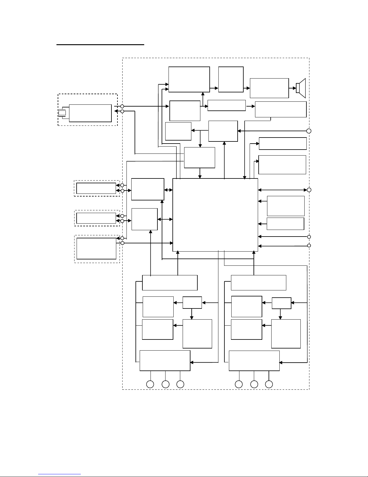
8-2.Block diagram
Volume circuit
Power
amplifier
Pre
-Amplifier
Comparator
Phase detection
Chargin
g circuit
Power
circuit
Battery
CPU
Power LED
STOP
switch
Power
Doppler probe
Temperature
probe
USB
PPG
/ PV 2
Pressure sensor
Inflation
pump
Exhaust
valve
Cuff selector
circuit
D/A
Inflation
control
circuit
Cuff selector
circuit
D/A
PPG
PPG
PPG
/ PV 1
PPG Probe
PPG Probe
Temperature probe
AC adaptor
PPG/PV
Sound
Temperature Probe
Inflation
pump
Pressure
control
circuit
Pressure sensor
Exhaust
valve
Charging LED
Sound
circuit
Doppler Sound
Doppler Probe
Transducer
High frequency
circuit
Page 39

33
8-3.Specifications
Power: Ni-MH rechargeable battery pack or AC adaptor
AC adaptor: Model #: DPS54-M
Input: AC 100-240V, 50Hz/ 60Hz
Output: DC 15V, 4A or more
Consumption: DC 15V, 1.75 A
Recharge time Approx. 4 hours by the AC adaptor
Full charge life: Approx. 2 hours, approx. 10 times of automatic testing
Battery life: Approx. 2 years
Measurement range;
Blood pressure: Oscillometry: 50 to 260 mmHg
Doppler: 30 to 260 mmHg
Heart rate: Oscillometry: 30 to 200 BPM
Doppler: 30 to 240 BPM
Accuracy;
Blood pressure: Oscillometry: ± 5 mmHg
PPG/Doppler: ± 5 mmHg
Heart rate: ± 5%
Temperature: ± 0.5°C
Velocity: ± 10%
Doppler probe, option: Frequency Acoustic power Ispta* (In situ)
8MHz 720 mW/cm² or less
*Ispta: Spatial Peak – Temporal Average Intesity
Speaker output: 250 mW
External output: USB port
Electrical safety: Conform to EN60601-1
Internally powered equipment
Type BF applied part.
Operating environment: 10 to 40°C
85% humidity or less with no condensation
Storage environment: 0 to 50°C
85% humidity or less with no condensation
Page 40
34
Transportation environment:
0 to 50°C
85% humidity or less with no condensation
Dimensions: Main unit: 300 (W) x 244 (H) x 167 (D) mm
Weight: Approx. 3.5kg (Without AC adaptor and components)
Manufacturing date: The first 2 digits and following 2 digits of the serial number
represent the year and month of manufacturing, respectively.
Examples:
14010001: Jan/ 2014
1401001: Jan/ 2014
* Specifications subject to change
8-4.Safty standards
The unit confirms to the following standards:
Manufacturing standard: EN60601-1
(1) Protection class against electric shock: Class II device
Protection grade against electric shock: Type BF applied part
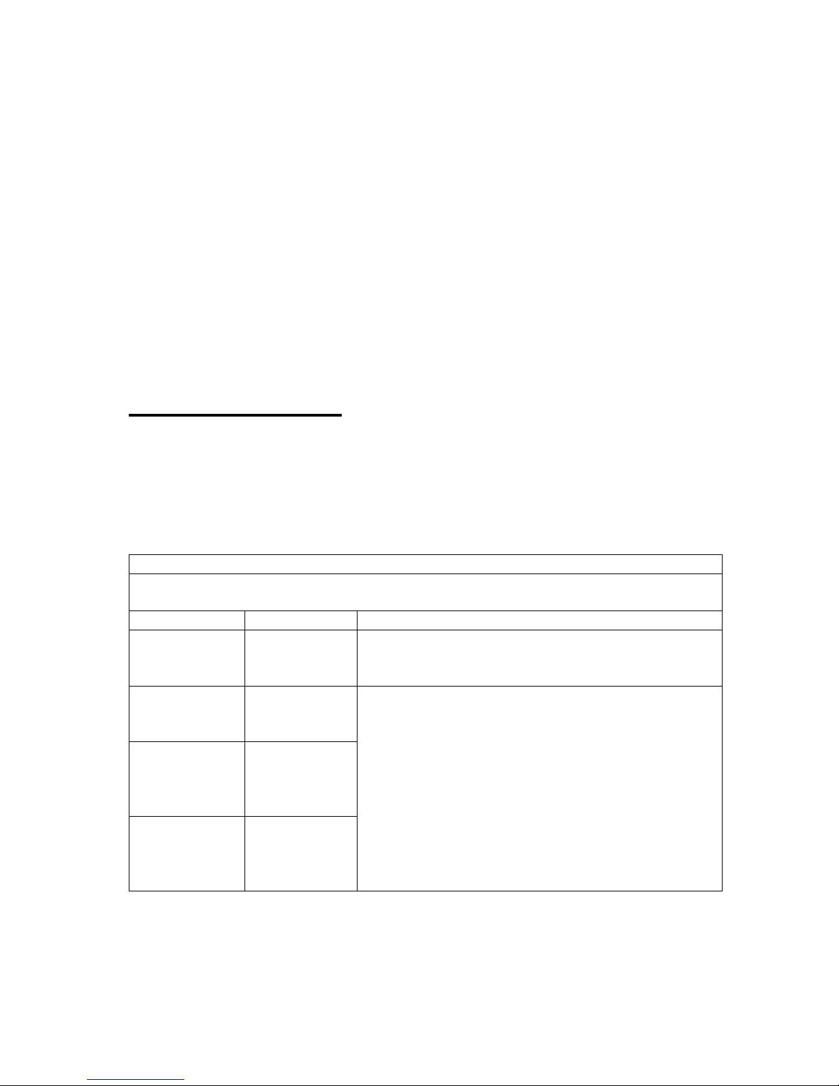
(2) Guidance and manufacturer's declaration - electromagnetic emissions and immunity.
Guidance and manufacturer’s declaration – electromagnetic emissions
The Smartdop XT is intended for use in the electromagnetic environment specified below. The
customer or the user of the Smartdop XT should assume that it is used in such an environment.
Emissions test
compliance
Electromagnetic environment - guidance
RF emissions
CISPR 11
Group 1
The Smartdop XT use RF energy only for its internal function.
Therefore, its RF emissions are very low and are not likely to
cause any interference in nearby electronic equipment.
RF emissions
CISPR 11
Class A
The Smartdop XT is suitable for use in all establishments
other than domestic, and may be used connected to the public
low-voltage power supply network that supplies buildings used
for domestic purposes provided the following warning in
needed:
Warning: This equipment/system is intended for use by
healthcare professions only. This equipment/system may
cause radio interference or may be necessary to take
mitigation measures, such as re-orienting or relocating the
Smartdop XT or shielding the location.
Harmonic
emissions
IEC61000-3-2
Class A
Voltage
fluctuations/
flicker emissions
IEC61000-3-3
Complies
Page 41

35
Guidance and manufacturer’s declaration – electromagnetic immunity
The Smartdop XT is intended for use in the electromagnetic environment specified below. The
customer or the user of the Smartdop XT should assure that it is used in such an environment.
Immunity test
IEC60601 test level
Compliance level
Electromagnetic environment
- guidance
Electrostatic
discharge(ESD)
IEC61000-4-2
±6kV contact
±8kV air
±6kV contact
±8kV air
Floors should be wood,
concrete or ceramic tile. If
floors are converted with
synthetic material, the relative
humidity should be at least
30 %.
Electrical fast
transient/burst
IEC61000-4-4
±2kV for power supply
lines
±1kV for input/output
lines
±2kV for power supply
lines
±1kV for input/output
lines
Mains power should be that of
a typical commercial or
hospital environment.
Surge
IEC61000-4-5
±1kV differential mode
±2kV common mode
±1kV differential mode
±2kV common mode
Mains power should be that of
a typical commercial or
hospital environment.
Voltage dips,
short
interruptions and
voltage variations
on power supply
input lines
IEC61000-4-11
<5% U
T
(>95% dip in UT)
for 0,5 cycles
40% UT
(60% dip in UT)
for 5 cycles
70% UT
(30% dip in UT)
for 25 cycles
<5% UT
(>95% dip in UT)
for 5 s
<5% U
T
(>95% dip in UT)
for 0,5 cycles
40% UT
(60% dip in UT)
for 5 cycles
70% UT
(30% dip in UT)
for 25 cycles
<5% UT
(>95% dip in UT)
for 5 s
Mains power should be that of
a typical commercial or
hospital environment.
Power frequency
(50/60Hz)
magnetic field
IEC61000-4-8
3 A/m
3 A/m
Power frequency magnetic
fields should be at levels
characteristic of a typical
location in a typical
commercial or hospital
environment.
NOTE UT is the a.c. mains voltage prior to application of the test revel.
Guidance and manufacturer’s declaration – electromagnetic immunity
The Smartdop XT is intended for use in the electromagnetic environment specified below. The
customer or the user of the Smartdop XT should assure that it is used in such an environment.
Immunity test
IEC60601 test level
Compliance
level
Electromagnetic environment - guidance
Page 42
36
Conducted RF
IEC61000-4-6
Radiated RF
IEC61000-4-3
3Vrms
150kHz to 80MHz
3V/m
80MHz to 2.5GHz
3V
3V/m
Portable and mobile RF communications
equipment should be used no closer to any
part of the Smartdop XT, including cables,
than the recommended separation
distance calculated from the equation
applicable to the frequency of the
transmitter.
Recommended separation distance
d = 1,2√P
d = 1,2√P 80 to 800MHz
d = 2,3√P 800MHz to 2,5GHz
where P is the maximum output power
rating of the transmitter in watts (W)
according to the transmitter manufacturer
and d is the recommended separation
distance in meters (m).
Field strength from fixed RF transmitters,
as determined by an electromagnetic site
survey, a should be less than the
compliance level in each frequency range.
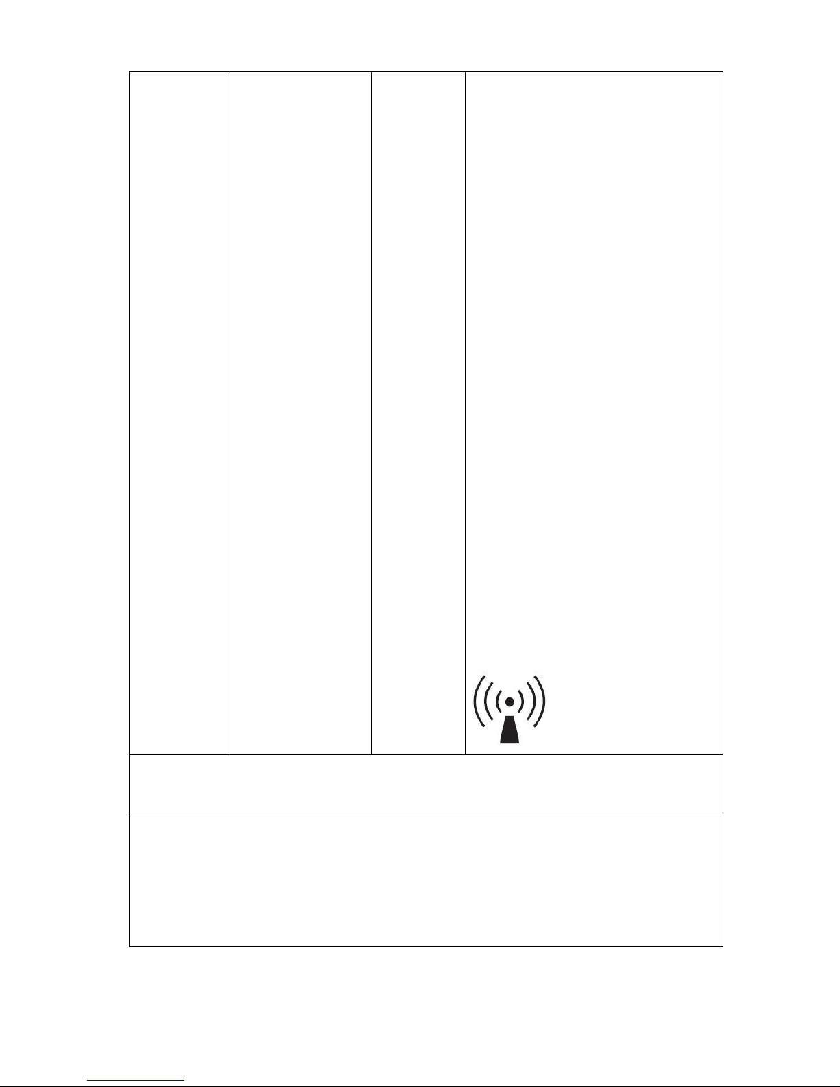
b
Interference may occur in the vicinity of the
equipment marked with the following
symbol:
NOTE 1 At 80 MHz and 800 MHz, the separation distance for the higher frequency range applies.
NOTE 2 These guidelines may not apply in all situations. Electromagnetic propagation is affected by
absorption and reflection from structures, objects and people.
a Field strengths from fixed transmitters, such as base stations for radio (cellular/cordless) telephones
and land mobile radios, amateur radio, AM and FM radio broadcast and TV broadcast cannot be
predicted theoretically with accuracy. To assess the electromagnetic environment due to fixed RF
transmitters, an electromagnetic site survey should be considered. If the measured field strength in
the location in which the Smartdop XT is used exceeds the applicable RF compliance level above,
the Smartdop XT should be observed to verify normal operation. If abnormal performance is
observed, additional measures may be necessary, such as reorienting or relocating the Smartdop
XT.
b Over the frequency range 150 kHz to 80 MHz, field strengths should be less than 3 V/m.
Page 43

Page 44

April, 2015
080-00198-1.0
Manufactured by
Hadeco, Inc.
2-7-11 Arima, Miyamae-ku, Kawasaki,
Kanagawa, 216-0003 Japan
 Loading...