

Page 1

Page 2

Page 3

TABLE OF CONTENTS
Cautions
1. Introduction ...................................................................................................................... 1
1-1. Features .................................................................................................................... 1
1-2. Clinical applications ................................................................................................... 2
1-3. Probe selection ......................................................................................................... 3
1-4. Contents in package ................................................................................................. 3
2. Appearance ..................................................................................................................... 4
2-1. View .......................................................................................................................... 4
3. Quick start ........................................................................................................................ 8
3-1. Turning the unit ON ................................................................................................... 8
3-2. Charging / Discharging battery .................................................................................. 9
3-3. Checking battery level ............................................................................................... 9
3-4. Setting printer paper ................................................................................................ 10
3-5. Measuring Blood Velocity ........................................................................................ 11
3-6. Ankle brachial pressure index (ABI) ........................................................................ 12
3-7. Toe brachial pressure index (TBI) ........................................................................... 15
3-8. PV – Arterial studies ................................................................................................ 16
3-9. Measuring Fetal Heart Rate .................................................................................... 17
3-9-1. Functions .......................................................................................................... 17
3-9-2. Operating panel ................................................................................................ 17
3-9-3. OPERATION .................................................................................................... 18
4. Mode settings ................................................................................................................ 19
4-1-1. Basic Modes ..................................................................................................... 19
4-1-2. Measurement / Freeze Mode ........................................................................... 19
4-2. Menu mode ............................................................................................................. 20
4-2-1. Menus .............................................................................................................. 20
4-2-2. Menu Operation ................................................................................................ 21
4-2-3. Menu for Blood Velocity Measurement Mode ................................................... 22
4-2-4. Menu for Blood Velocity Freeze Mode ............................................................. 22
4-2-5. Menu for Pressure Mode .................................................................................. 23
4-2-6. Menu for PV-AC Mode ..................................................................................... 23
4-2-7. Menu Mode Details .......................................................................................... 24
a. MEMORY - STORE ............................................................................................ 24
b. MEMORY - READ ............................................................................................... 24
c. MEMORY - CLEAR ............................................................................................. 25
d. DIR (Flow direction) ............................................................................................ 25
e. DISP / OTHERS - DISP (Waveform / Data) ........................................................ 25
f. WAVEFORM (Freeze mode only) ........................................................................ 26
g. GUIDANCE ......................................................................................................... 26
h. P.CLEAR (Clearing blood Pressure data) ........................................................... 27
i. CURSOR (Mode for adjusting systolic pressure point) ......................................... 27
j. P.DISP (Displaying/erasing Pressure value) ........................................................ 27
k. OTHERS - LANGUAGE ...................................................................................... 27
l. OTHERS - PRB-KEY (Probe button function) ...................................................... 28
Page 4

m. OTHERS - CALibration ...................................................................................... 28
n. OTHERS - CAL PRINT (Printing Calibration) ...................................................... 28
o. OTHERS - BACKLIGHT ...................................................................................... 28
p. OTHERS - AUTO-OFF (Automatic shut-off) ....................................................... 29
q. OTHERS - DISCHARGE ..................................................................................... 29
4-3. Shortcut keys .......................................................................................................... 30
4-4. External outputs ...................................................................................................... 30
4-4-1. Headset ............................................................................................................ 30
4-4-2. Communication Port ......................................................................................... 30
4-5. Symbol list ............................................................................................................... 31
5. Display and Printing ....................................................................................................... 32
5-1. Arterial and venous blood velocity modes ............................................................... 32
5-1-1. Waveforms on LCD .......................................................................................... 32
5-1-2. Parameters ....................................................................................................... 33
5-1-3. Printing Waveform and Numerical Data ........................................................... 33
5-1-4. Print Samples ................................................................................................... 34
5-2. ARM / LEG and TOE pressure modes .................................................................... 35
5-2-1. Display Samples in Pressure Measurement Process ....................................... 35
5-2-2. Optional Functions ........................................................................................... 35
5-2-3. Error Messages ................................................................................................ 36
5-2-4. Print Samples ................................................................................................... 36
5-3. PV arterial mode (PV-AC) ....................................................................................... 37
5-3-1. Waveforms on LCD .......................................................................................... 37
6. Maintenance .................................................................................................................. 38
6-1. Performance check by user .................................................................................... 38
6-2. Cleaning .................................................................................................................. 38
6-3. Warranty ................................................................................................................. 39
7. Options .......................................................................................................................... 39
7-1. Probe selection: ...................................................................................................... 39
7-2. Others: .................................................................................................................... 40
7-3. Photoplethysmograph ............................................................................................. 40
7-3-1. PPG (Photoplethysmography) Probe Assemblies ............................................ 40
7-3-2. PPG - Arterial Pulse Waveform Studies ........................................................... 40
7-3-3. PPG - Venous Reflux Study ............................................................................. 41
7-3-4. Menu for PPG ................................................................................................... 44
7-3-5. PPG Mode Settings .......................................................................................... 44
7-4. Pneumoplethysmograph ......................................................................................... 45
7-4-1. PV (Pneumoplethysmography) Probe Assemblies ........................................... 45
7-4-2. PV - Measurement of Maximum Venous Outflow ............................................. 45
7-4-3. Menu for PV ..................................................................................................... 47
7-4-4. PV Mode Setting .............................................................................................. 47
8. Technical Information..................................................................................................... 48
8-1. Principles ................................................................................................................ 48
8-2. Block diagram ......................................................................................................... 49
8-3. Specifications .......................................................................................................... 50
8-4. Safety standards ..................................................................................................... 52
Page 5

Cautions
Please read the following important points carefully before you operate the unit.
1. Only skilled persons should operate the unit.
2. Use the unit for measuring blood flow.
3. Do not apply any modification to the unit.
4. Device placement
Follow the requirements for storage and operating environments.
(1) Do not place it near water.
(2) Dot not place it where atmospheric pressure, temperature, humidity, ventilation,
sunlight, dust, salt, sulfur and so forth will affect the unit adversely.
(3) Pay attention to the stability conditions to avoid too much inclination, vibration,
shock and so on during transportation and installation of the unit.
(4) Do not place it where chemicals are stored or gas may be generated.
(5) Do not place it where the unit tends to fall.
(6) Do not place it on or adjacent other electronic devices.
5. Before use
(1) Make sure that the unit operates safely and correctly by implementing
performance check mentioned in "§ 6-1. Performance check by User".
(2) Make sure that all cables are connected correctly and safely.
(3) Using it with other equipment together may cause a misdiagnosis or danger to
patient due to a malfunction.
(4) Double-check that all the cables do not obstruct any external connection to the
patient.
(5) Do not sterilize the main unit and non-sterilizable probe to prevent any damage.
6. Operation
(1) Do not use the unit simultaneously with either electric cautery, cardioverter, other
ultrasonic device or mobile phone.
(2) Be careful not to exceed time and volume of diagnosis treatment required.
(3) Always make sure the unit and patient are not under abnormal conditions.
(4) When any abnormality is found on the unit or the patient, take proper action such
as stopping use of the unit in a manner safe for the patient.
(5) In case of emergency or unexpected situations, take the following action(s) to
stop the inflation of the cuff:
• Press INF/DUMP button to dump the pressure.
• Disconnect the tubing from the unit.
• Turn the unit off.
(6) Do not let the patient touch the unit.
(7) Use the designated components only.
Page 6

(8) Do not use the components for other devices.
(9) Use the unit under the operating environments specified on the specifications.
(10) Use the unit as specified in the operation manual.
(11) Do not use the unit in a strong electromagnetic field or it may cause incorrect
measurements.
7. After use
(1) Return all switches to the conditions before use and turn the unit off the way
specified.
(2) Do not pull the cable(s) too much while disconnecting or it may cause damage.
(3) Clean the unit, AC adaptor, cables and probes and place them in right place for
the next use.
8. Storage
(1) Follow the caution (1) to (5) of section #4 Device placement in the previous page.
(2) Clean the unit, AC adaptor, cables and probes and place them in right place for
the next use.
(3) When using the unit next time, perform the maintenance to make sure it works
properly and safety.
9. Maintenance
(1) Do the periodical maintenance by following the procedures mentioned in "§ 6-1.
Performance Check by User".
(2) The maintenance must be done at least once a year.
10. Probes
(1) Clean the probe using damp cloth before use. Using alcohol or thinner may
damage the probe.
(2) The probe transducer tip is very thin and delicate. Please handle with great care
and use the probe cap when not in use.
11. Ultrasonic gel
(1) Do not apply ultrasonic gel to the probe body other than the tip of probe.
(2) Using other materials such as baby oil and cream may damage the probe.
(3) The ultrasonic gel enclosed is non-sterile and do not use it for surgeries.
(4) Incidence of allergy: Discontinue use of gel if any allergic reaction occurs.
12. Battery
(1) When battery is extremely low, the LCD display will not operate. Also there will be
no speaker sounds. Charge the battery.
(2) Battery life is 300 full charges. When full charging life is obviously short, contact
your dealer for replacing battery.
13. For transportation of the unit, it should be packed properly to protect against shock.
14. Repair services
(1) When the unit gets out of order, contact the dealer for repair from whom you
Page 7

purchased the unit.
(2) Only authorized persons should perform the repair services.
15. Do not disassemble the unit.
16. Destruction
(1) In case of destruction of the unit, follow the instructions for disposal of the
destruction appointed by each country or local government.
(2) Do not place battery in a fire or it may cause an explosion and injury.
17. Any connected computer is not allowed to be in the patient area according to
IEC60601-1.
Page 8

1
1. Introduction
Thank you very much for choosing the Smartdop 30EX.
The Hadeco Smartdop 30EX is a uniquely designed bi-directional Doppler with backlit LCD
display and Doppler blood pressure monitor capability. It detects arterial and venous blood
flows in extremities as well as blood pressures of brachial, ankle and toe, calculates ABI
and TBI and fetal heart sounds.
Please read this manual carefully to acquaint yourself with the unit operation.
This medical device can be used by doctor for the purposes mentioned in "§ 1-2. Clinical
applications" for patient in hospital and clinic.
For the use with computer, refer to the operating manual for Windows linking software
optional.
1-1. Features
BI-DIRECTIONAL DOPPLER WITH BACKLIT LCD and PRINTER
Displays and prints velocity waveforms in bi-directional & dual separation channel and
numerical data.
DOPPLER BLOOD PRESSURE RECORDER
Full auto system with built-in cuff inflator
Shows instructions on LCD for measuring pressures if desired.
Calculates and prints ABI /TBI and velocity/pressure documentation.
TWO PROBE COMBINATIONS (for 2, 4, 5, 8, 10 MHz, PPG and PV)
The unit has dual probe connectors and selection switch.
Convenient for measuring pressures for TBI using with PPG.
Hadeco DESIGNED SMART MICROPROCESSOR
Various mode settings are available for optimal measurement with the menu displayed
on the LCD. 30 waveform memory.
BUILT-IN PULSE VOLUME with automatic cuff inflator.
CONVENIENT PROBE ACTIVATION BUTTON
Freezes waveform as well as FREEZE button.
Inflates and dump cuff as well as INF/DUMP button.
Button function can be changed on probe key mode setting, PRB-KEY.
USB COMPUTER INTERFACE
Transfers waveforms and numerical data to computer for data storage.
Page 9

2
Communication cable and Windows software are optional.
PPG and PV-MVO PROBES optionally available
Expands arterial & venous testing.
1-2. Clinical applications
Detections of fetal heart rate
Evaluation of fetal heart rate and sounds throughout pregnancy except where fetal heart is
not developed sufficiently during the first trimester.
Detections of arterial and venous blood flow velocity and pressures for
vascular disease
ABI and TBI studies
Bi-directional lower extremity studies.
PEAK & MEAN blood velocity determinations.
Peripheral vascular procedures.
Blood pressure segmental studies.
Venous compressions.
Penile & digit systolic pressures.
Toe pressure & venous reflux studies (PPG).
PV - Arterial studies
Note: The Smartdop 30EX and associated Doppler probes, inflatable cuffs, and optional
photoplethysmography probe are not intended for use in contact with blood or mucous
membrane.
CONTRAINDICATIONS
Do not use the Smartdop 30EX for ophthalmic or periordical studies as the acoustic
intensity is higher than the level recommended by authorities for use on and around the
eye.
Page 10

3
1-3. Probe selection
The frequency of diagnostic ultrasound is inversely proportional to depth of penetration.
The Smartdop has 5 interchangeable probes with different frequencies. Use those probes
depending on your applications.
BT2M20S8C (2MHz): Fetal heart rate
BT4M05S8C (4 MHz): Deep peripheral blood velocity and flow
BT5M05S8C (5 MHz): Deep peripheral blood velocity and flow
BT8M05S8C (8 MHz): Superficial blood velocity and flow
BT10M5S8C (10 MHz): Superficial blood velocity and flow
Note: One of these probes comes with Smartdop as a standard component. Other probes are
available as optional components.
1-4. Contents in package
Main unit ................................................ 1
Probe ....................................................... 1
AC adaptor (GMPU18UI-3) ..................... 1
Ultrasonic gel (AQUAULTRA BASIC) ...... 1
Paper ....................................................... 1
Blood pressure cuff (VC-12) .................... 1
Tubing ..................................................... 1
Page 11
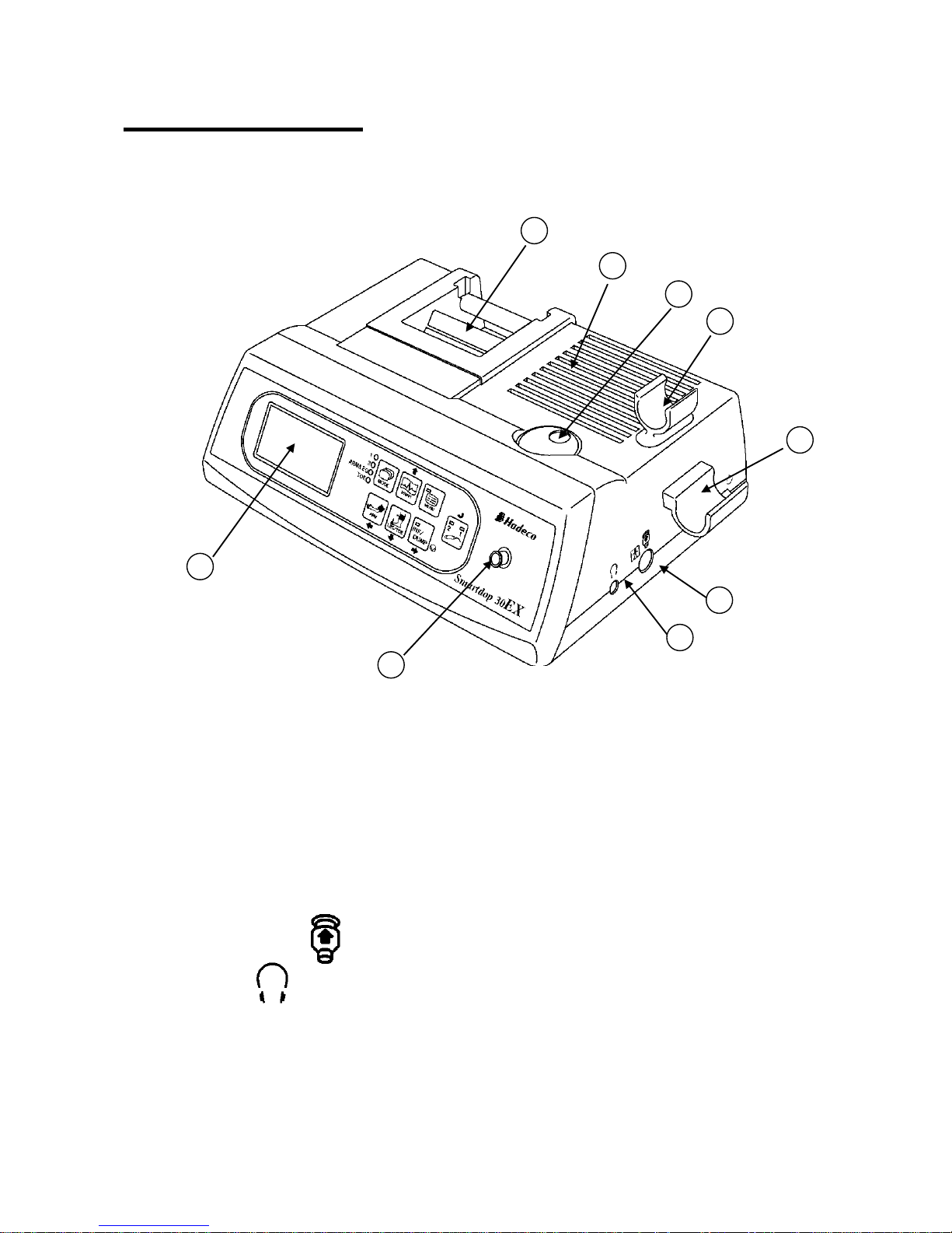
4
2. Appearance
2-1. View
Front Right View
1. Printer: To print velocity wave forms, systolic pressures, ABI / TBIs
and velocity / pressure documentations and PPG / PV
waveforms.
2. Speaker: Outputs Doppler sounds.
3. Volume control: To adjust sound volume.
4. Probe holder #2: For probe placement when not in use.
Probe holder #2 can be removed by removing the 2
screws. Fix them to the unit.
5. Probe holder #1: For probe placement when not in use.
6. Probe connector #1: To connect probe #1.
7. Headset: To connect headset. It cuts off the speaker.
8. Inflation inlet: To connect the tubing for the blood pressure cuff.
9. LCD display: Displays waveform, numerical data, and menu for mode
settings.
8
9
6
4 3 2
1
7
5
Page 12
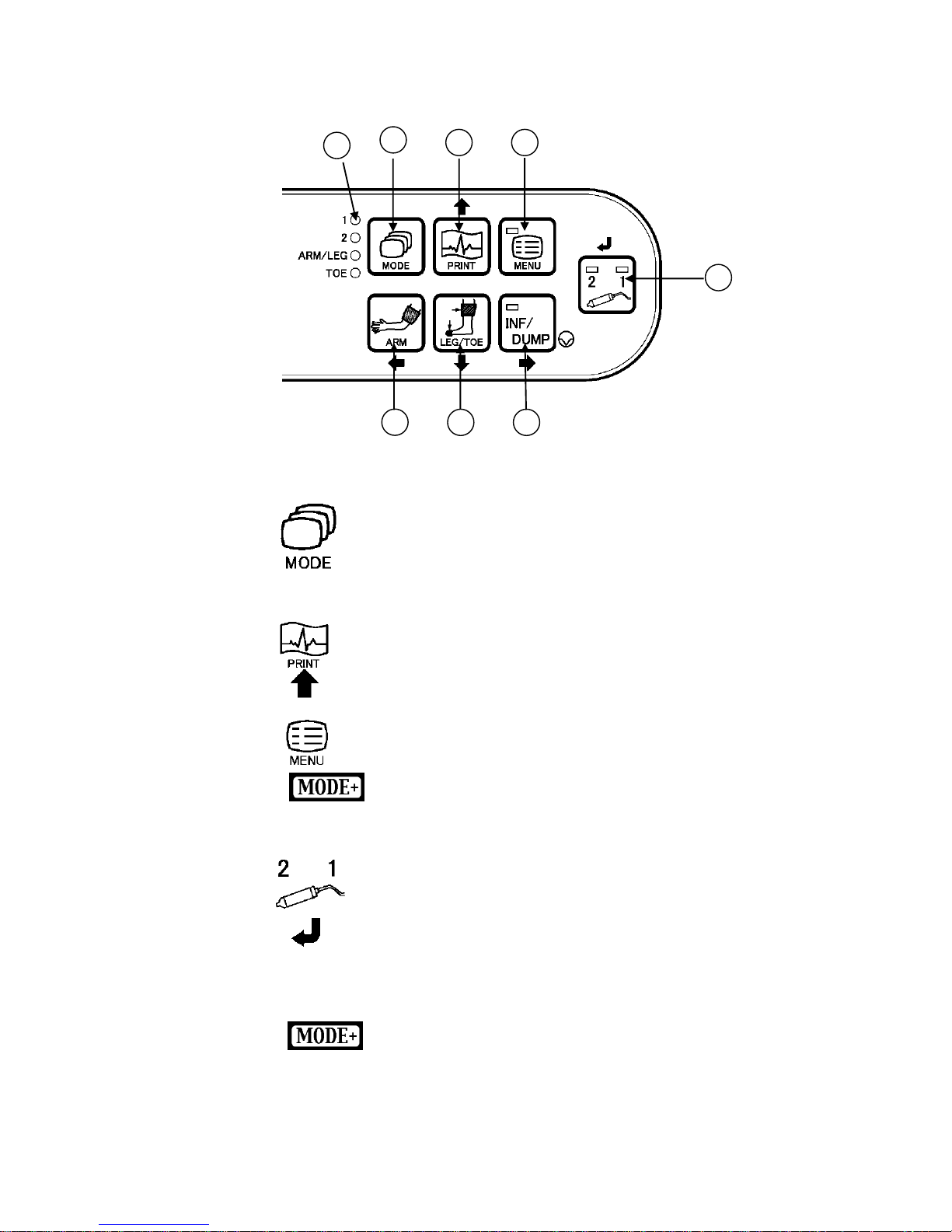
5
Enter
Operating Panel
10. Mode LEDs: Indicate the mode selected. (Mode 1, Mode 2, ARM/LEG,
TOE) Illuminate sequentially while charging battery.
11. MODE button: To select the mode of either the arterial Mode 1, venous
Mode 2, ARM/LEG pressure or TOE pressure mode. See
“§ 4-1-1. Basic Modes” for details.
When optional PPG/PV probe is connected, Mode 1 and
Mode 2 correspond to AC and DC modes respectively.
12. PRINT button: To activate and deactivate the printer.
Menu mode
To move the cursor up.
13. MENU button: To go to menu mode. See “§ 4-2. Menu Mode” for details.
To turn backlight on/off.
14. Probe selection button: To select the probe intended to use from the connected
probes. The LED corresponding to the probe number will
illuminate.
To select PV Arterial mode and both of LED will illuminate.
When displaying stored waveforms on Freeze mode:
To increase memory #.
To decreases memory #
Menu mode
To fix the mode or value.
To change the mode or setting.
14
17
16
15
Up
11
10
12
13
Page 13
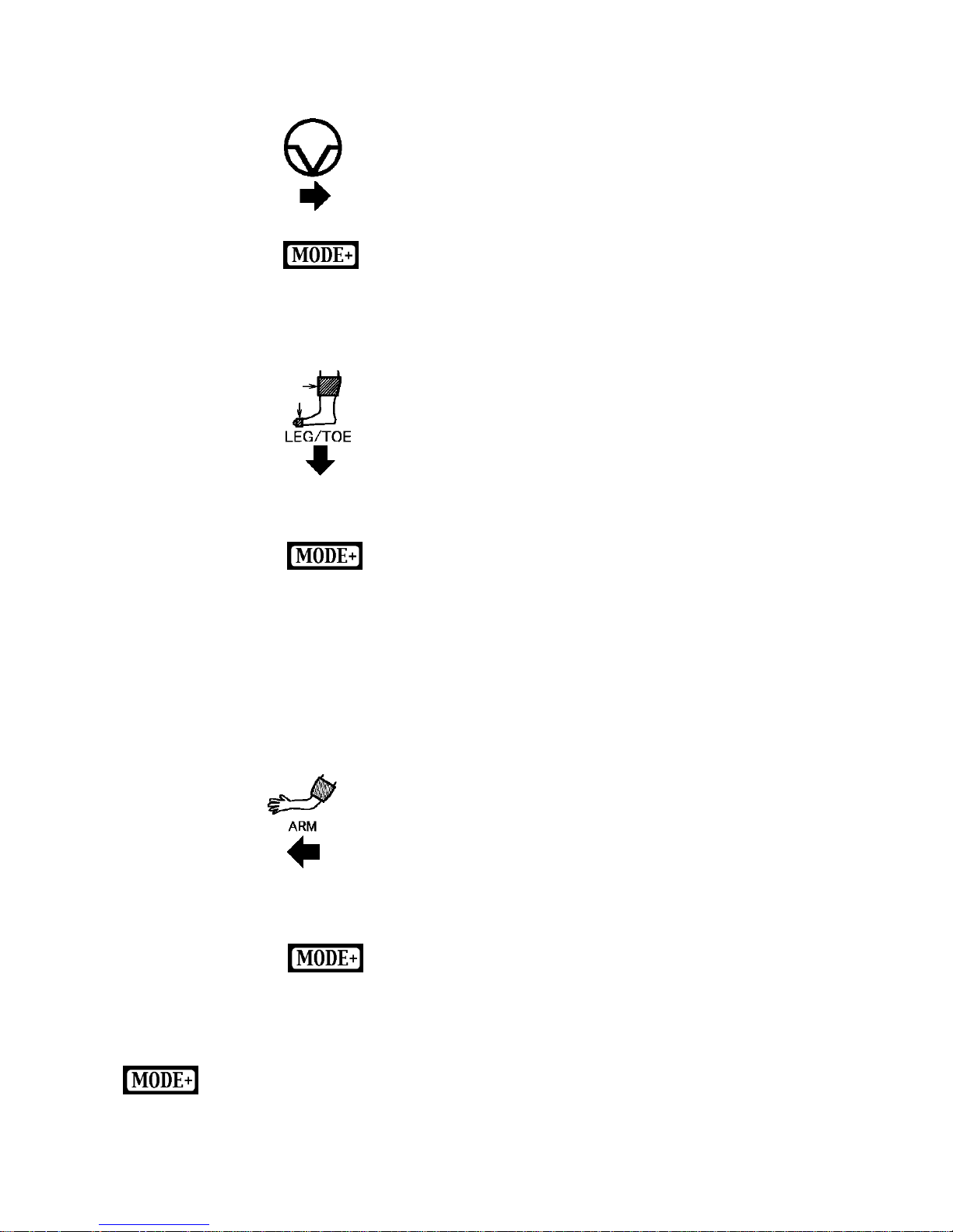
6
15. INF/DUMP button: To freeze / unfreeze the waveform.
Measuring pressure
To inflate / dump the blood pressure cuff.
To move cursor (systolic pressure point) to the right.
Menu mode
To move the cursor right.
To change the mode or setting.
16. LEG/TOE button: Measuring pressure
To store and display the measured pressure value as a
leg or toe pressure. (Freeze mode)
To display ABI or TBI (Measurement mode)
To erase measured pressure data by pressing longer than
2 sec. (Measurement mode)
To magnify the view of waveform.
Measuring blood velocity
To change the Display mode. (Waveform / Numerical
data)
Menu mode
To move the cursor down.
17. ARM button: Measuring pressure
To store and display the measured pressure value as an
arm (brachial) pressure. (Freeze mode)
To display ABI or TBI. (Measurement mode)
To erase measured pressure data by pressing longer than
2 sec. (Measurement mode)
To move cursor (systolic pressure point) to the left
Menu mode
To go back to previous menu or to get out of menu mode.
means to press and hold MODE button before pressing each button.
Freeze
Right
Down
Left
Page 14
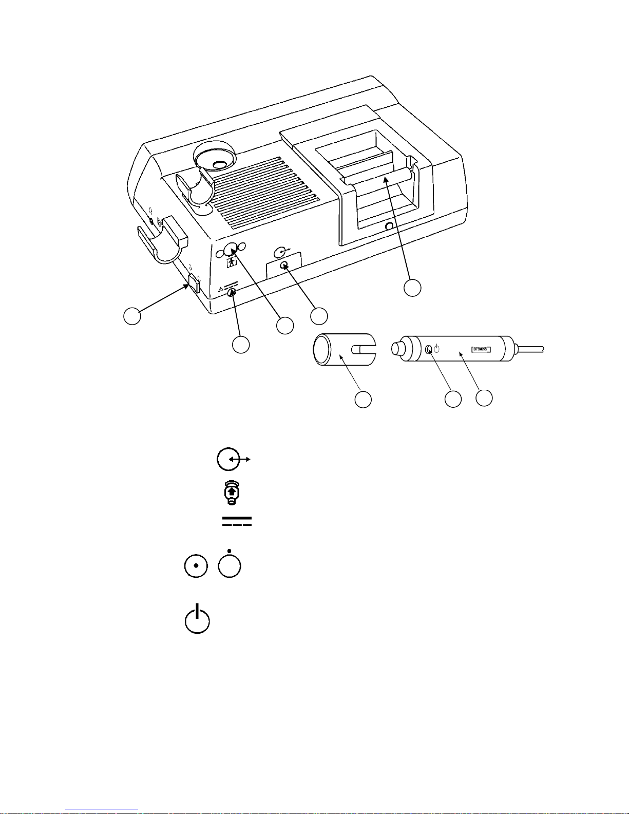
7
Back Right View and Probe
18. Roll shaft: To set paper roll.
19. Communication port: To connect computer. (USB)
20. Probe connector #2: To connect probe #2.
21. AC adaptor connector: To connect the designated AC adaptor.
22. Power switch: To turn on/off the unit.
23. Probe: Multi-probe selection of 2, 4, 5, 8 and 10 MHz
24. Probe button: To freeze and unfreeze the waveform.
To activate and deactivate cuff inflator.
Note: The function is defined in the menu PRB-KEY. See § 4-2-7-l. OTHERS - PRB-KEY” for
details.
25. Probe cap: To protect the probe transducer tip when probe is not in
use.
24
25
23
18
19
20
21
22
ON OFF
Page 15
8
3. Quick start
For the first time of use and in case the unit has not been used for a while, fully charge the
internal battery.
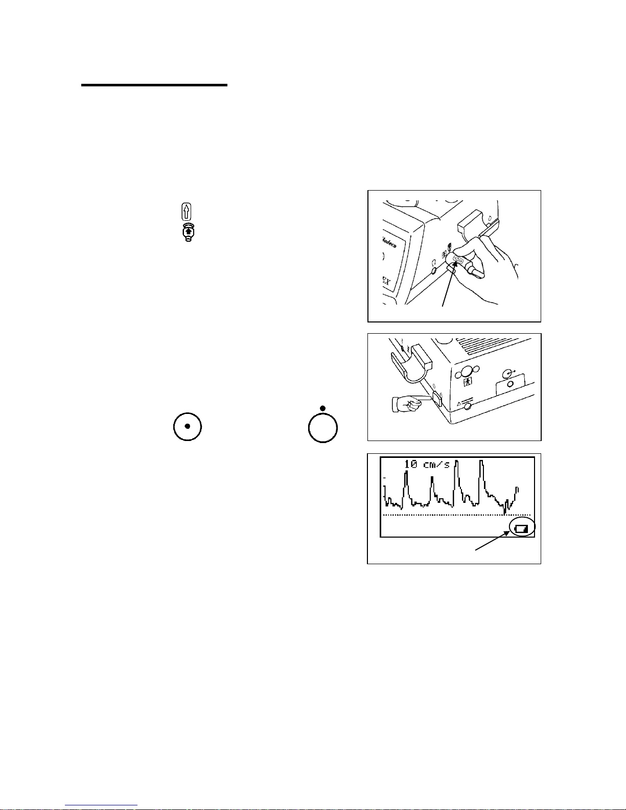
3-1. Turning the unit ON
(1) Connect the probe to the probe connector so that
the arrow mark will be placed under the Probe
connector mark .
(2) Press the power switch to turn the unit ON.
Note: When battery is low, low battery indicator appears as
shown right. The unit can be used for a few more
minutes however, we recommend recharging battery
as soon as possible for further use.
AUTOMATIC SHUT-OFF:
When the AUTO-OFF is ON, if the unit is left on without AC adaptor connected, the power
is automatically shut off after following time passes:
(a) 5 minutes when no signal.
(b) 15 minutes when on measurement.
(c) 10 minutes when on freeze mode.
Note: If automatic shut-off functions while on freeze mode, the unit will resume the waveform on
freeze mode by turning the unit on.
Low battery indicator
Power switch
Power ON:
Power OFF:
Arrow mark
Page 16
9
3-2. Charging / Discharging battery
Charging battery:
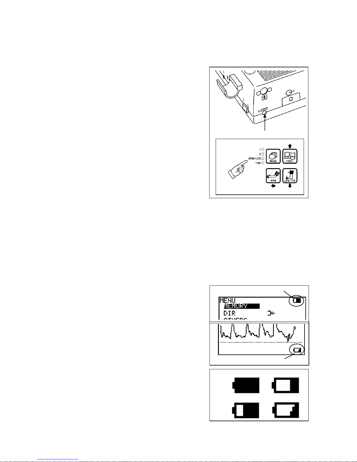
(1) Turn the unit off and plug the AC adaptor to the
unit to charge battery. The Mode LEDs will
illuminate sequentially (one after another) while
charging is in progress.
Note1: Use the designated AC adaptor.
Model name: GMPU18UI-3
Note2: Charging battery with AC adaptor while in use may
cause unnecessary power-supply noise.
When the battery is fully charged, the Mode LEDs
will be turned off. Unplug the AC adaptor.
Discharging battery:
Using and charging the battery repeatedly without fully discharging may cause a shorter
full charge battery life. Fully discharge battery before charging every once in a while. See
“§ 4-2-7-q. OTHERS -DISCHARGE” how to do it.
3-3. Checking battery level
Battery level indicator shows upper right of the menu
screen.
(1) Turn the unit on and press MENU button to display
the menu.
When battery is low, low battery indicator will be
shown on bottom right of LCD as shown in the
right. Charge the battery when in low.
Note: Battery level indicator shows the battery level in 4
steps as shown right.
Full
30%
70%
Low
Low battery indicator
Battery level indicator
AC adaptor connector
Mode LEDs
Page 17
10
3-4. Setting printer paper
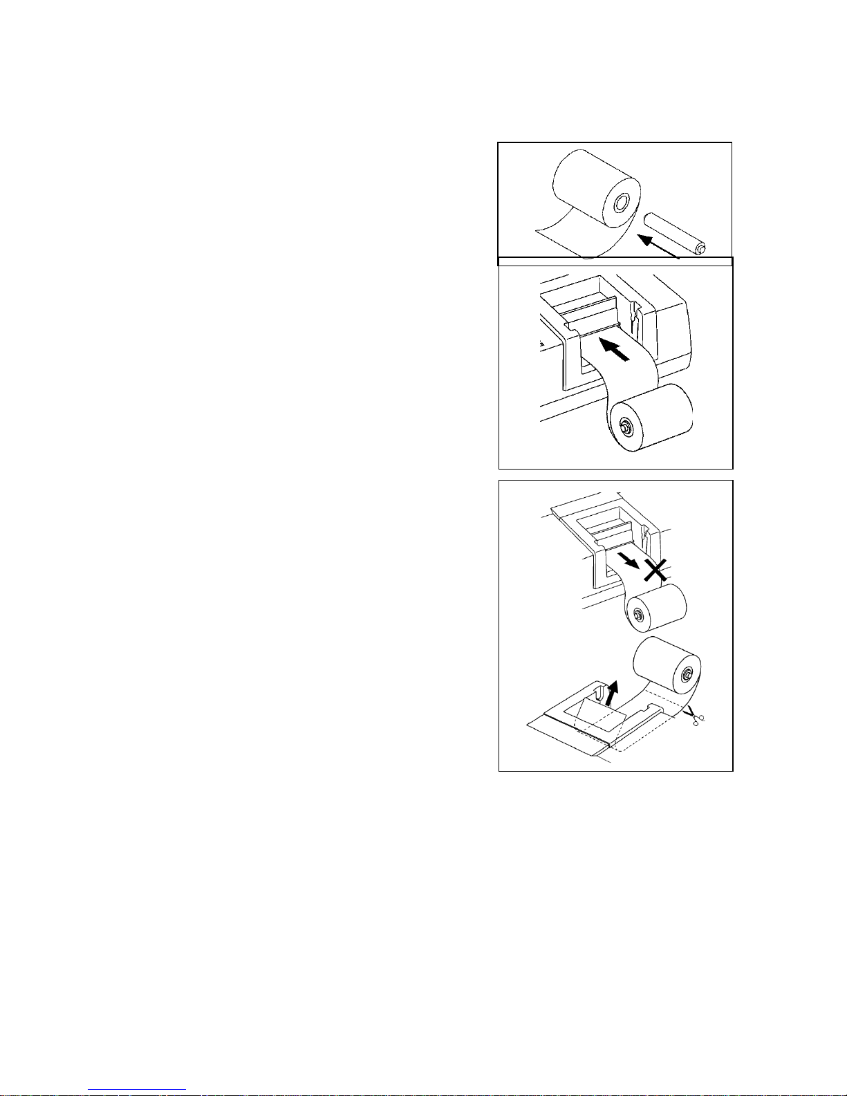
(1) Remove the roll shaft and set it into the paper roll.
Insert and hold the paper edge into the paper entry
under the printer and press the PRINT button.
(2) Press the button again when sufficient paper
comes out. Pull the paper edge out a few inches
and cut it at the paper guide. Put the roll shaft with
the paper back on the roller guide.
Note: Cut the paper straight before inserting the paper for
loading it easily. Apply slight fingertip pressure to
the paper at beginning of insertion.
Caution:
Do not pull paper in a direction opposite to the
direction of paper feed (printing and auto loading). It
may cause malfunction of the printer.
In cases removing paper from printer, cut the paper at
the roll side and pull the remaining paper out in the
direction of paper feed.
Also paper feed problems like paper jam or wrinkled
paper hit by printer head or something may cause
malfunction of the printer. Insert the paper correctly by
following the steps mentioned above.
Page 18
11
3-5. Measuring Blood Velocity
This section explains typical operation of measuring blood velocity. Refer to Ҥ 5-1. Arterial
and venous blood velocity modes” and “§ 4-2. Menu Mode” for mode settings of various
uses.
(1) Connect the probe to the probe connector.
See the step# (1) in the “§.3-1. Turning the unit ON” for the details.
(2) Put ultrasonic gel on tip of probe or patient skin.
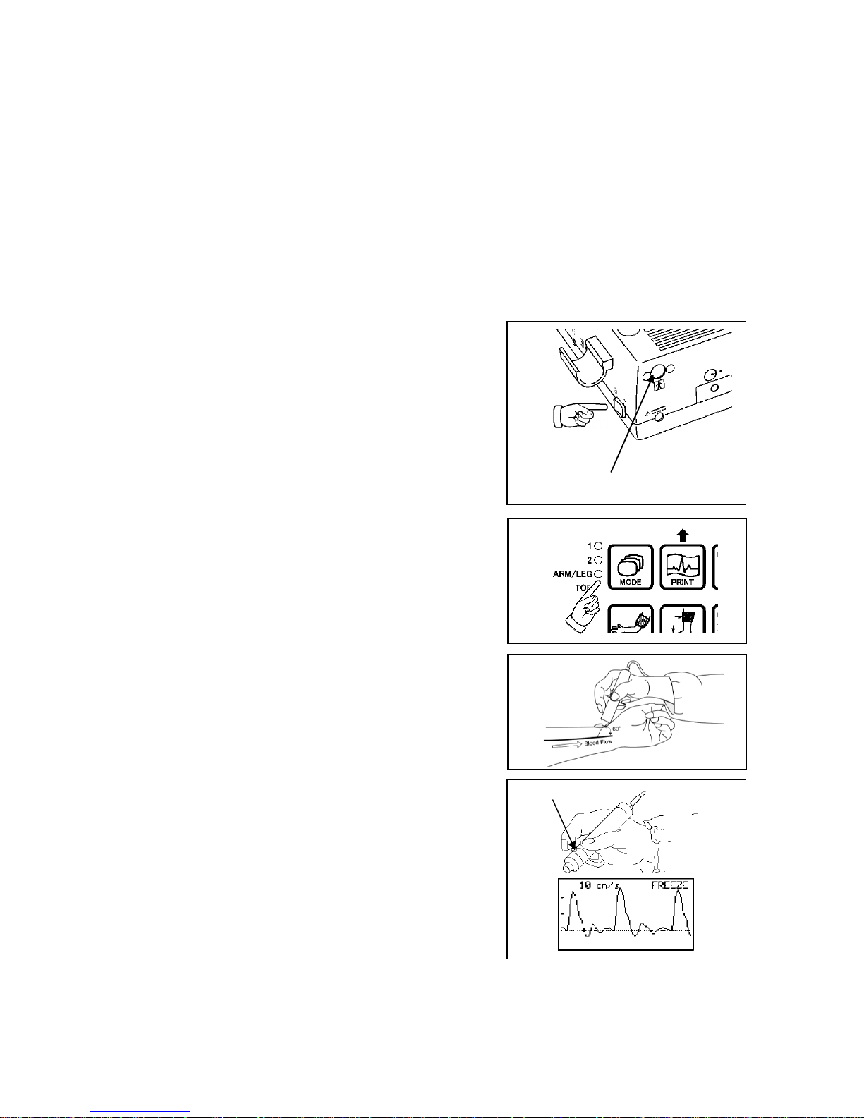
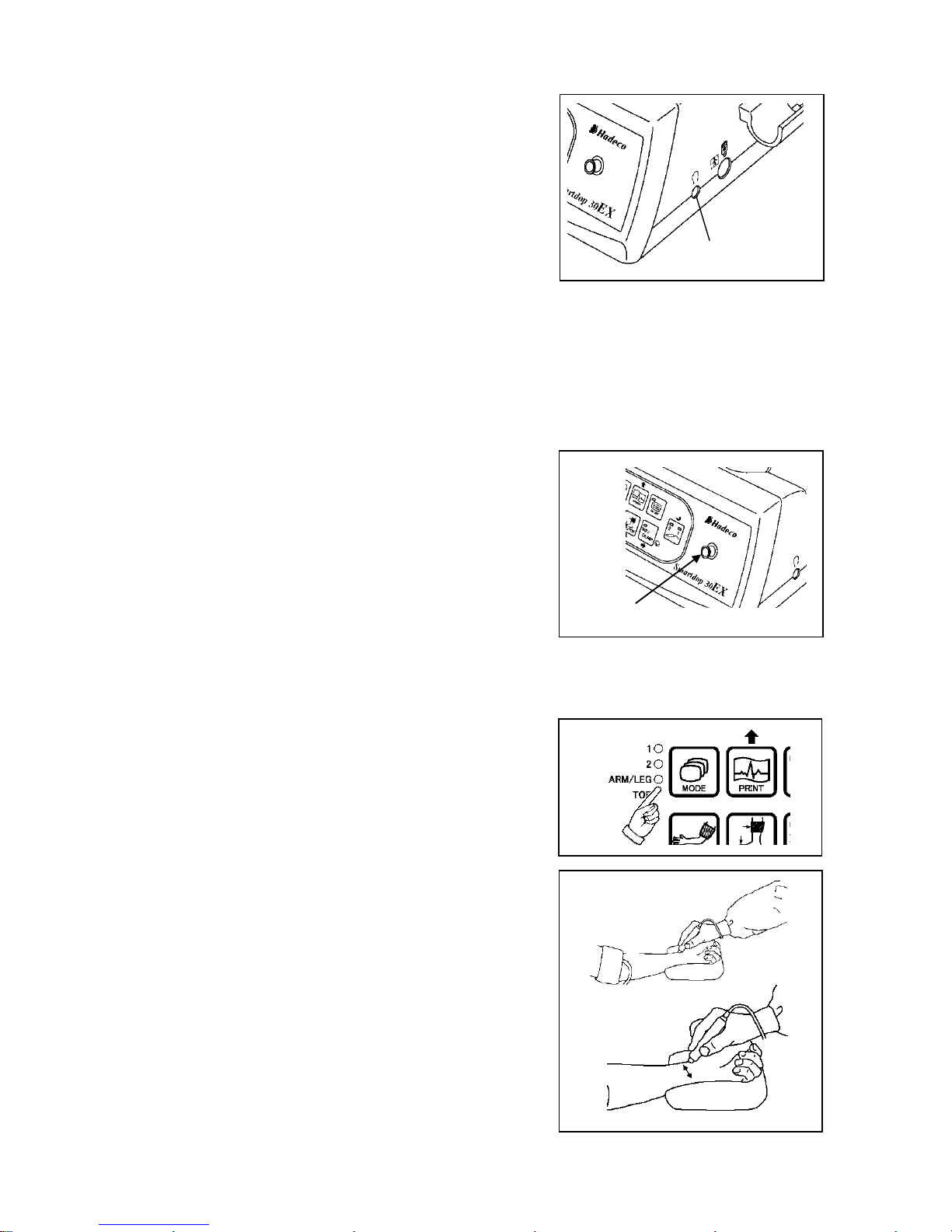
(3) Turn the unit on and turn the volume control to
maximum. Make sure the probe selection LED
illuminating corresponds to the connector you
connected probe. If not, press probe selection
button to change it.
(4) Press MODE button to select Mode 1 for arteries
or Mode 2 for veins.
(5) Put the probe on the measurement area and move
it slowly to locate the point where the maximum
Doppler sounds are heard. An ideal probe angle to
the vessel is approximately 45 to 60 degrees.
Wait more than 5 sec for MODE 1 (OR up to 25
sec for MODE 2) without moving probe after the
maximum Doppler sounds, press probe button (or
INF/DUMP button) to freeze the waveform. Press
PRINT button to print the waveform, if necessary.
Note: Function of the probe button can be selected from Freeze, Print, and Freeze & Print on PRB-
Key mode settings. See “§4-2-7-l.OTHERS - PRB-KEY (Probe button function)”.
Probe connector #2
Power switch
Probe button
Page 19
12
(6) Headset can be used to listen to Doppler sounds. It
will cut off the speaker.
If you wish to save the waveform and numerical
data on the memory, see Ҥ 4-2-7-a. MEMORY -
STORE”.
If you retry the measurement, press INF/DUMP
button or probe button to get out of the freeze
mode.
3-6. Ankle brachial pressure index (ABI)
(1) Connect the cuff VC-12 to the tubing and other end
of tubing to the inflation inlet as shown in the right.
(2) Connect the probe to the probe connector #1 or
#2.
See the step# (1) in the “§.3-1. Turning the unit ON” for the details.
(3) Turn the unit on and make sure the probe selection
LED illuminating corresponds to the connector you
connected probe. If not, press probe selection
button to change it.
Press MODE button to select ARM/LEG pressure
mode. (ARM/LEG LED will illuminate.)
Taking Arm pressure:
(4) Wrap the cuff above the elbow and apply the probe
to the radial or brachial artery at an angle of
approximately 45 to 60 degrees.
(5) Move the probe slowly to locate the point where
the maximum Doppler sounds are heard and the
INF/DUMP LED will blink after a few seconds.
Headset connector
Inflation inlet
Page 20
13
Note1: Once you locate the point, please keep the probe there until blood pressure is taken.
Note2: In case INF/DUMP LED doesn't blink due to low flow or arrhythmia, press INF/DUMP
button longer than 2 sec to activate cuff inflator manually in the next step #6.
(6) Press INF/DUMP or probe button to inflate the cuff.
The unit will stop the inflation at estimated 30
mmHg above the sound cessation and deflate the
cuff at 3 to 4 mmHg/sec automatically.
Note: In case the inflation doesn't stop automatically, press
INF/DUMP or Probe button to stop the inflation.
If an error message is displayed in the inflation and
deflation processes, press any button other than probe
selection button to delete the error message and go
back to step #5.
The LCD will show the systolic pressure when the
first Doppler sound is heard and then the cuff
pressure will be dumped automatically.
Press and hold MODE button and press Down
(LEG/TOE) to get on MAGNIFIED waveform mode
if desired. Do it again to go back to FULL waveform
mode.
If the systolic pressure is not satisfied, press and
hold MODE and press Right / Left to move the
cursor (vertical dotted line) to get it adjusted.
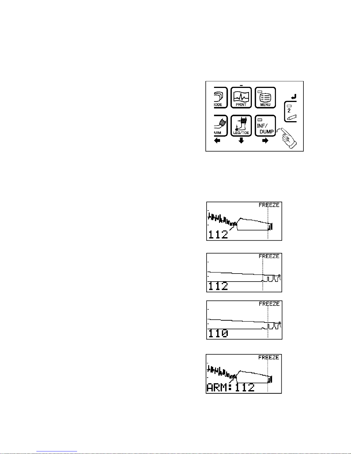
(7) Press ARM button to store it as the brachial
pressure and the LCD will show it as shown in the
right.
(8) Press INF/DUMP button to go back to the
measurement mode for ankle pressure.
Page 21
14
(9) Wrap the cuff above the ankle and apply the probe
to the posterior tibial artery at an angle of
approximately 45 to 60 degrees.
Taking Ankle pressure:
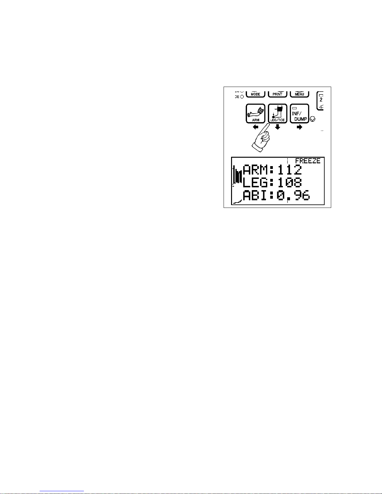
(10) Take the ankle pressure the same way for the
brachial. (Steps #5 to #6 of this section) Press the
LEG/TOE button to store it as the ankle pressure
and the ABI will be displayed as shown in the right.
(11) Go to the next ankle pressure on the other side.
Note: Press the ARM or LEG / TOE button more than 2 sec to clear the pressure data for the next
patient.
Page 22
15
3-7. Toe brachial pressure index (TBI)
Optional PPG probe (PG-21) is required for this testing.
(1) Take the brachial pressure in the same way as ABI. Follow steps #1 to 7 of "§ 3-6
Ankle brachial pressure index (ABI)".
(2) Remove arm cuff from tubing and replace with toe cuff, DVC-1.9 or DPC-2.5 for toe
pressures.
(3) Press MODE button to select toe pressure mode. (TOE LED will illuminate.)
(4) Connect PPG probe to the probe connector # 2 with the round polarity mark up on the
probe connector (12 o'clock).
(5) Press probe selection button to select probe #2.
(6) Wrap the cuff around the base of the big toe and
affix the PPG probe to the pad of the toe with
Velcro strap.
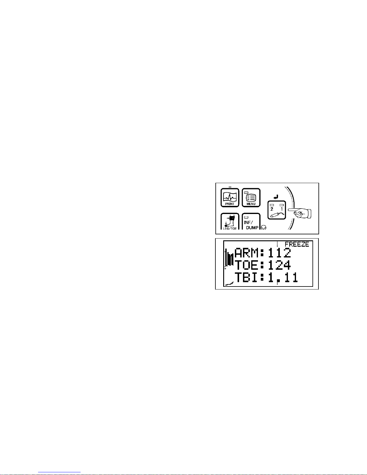
(7) Take the toe pressure the same way for the
brachial. Press the LEG/TOE button to store it as
the toe pressure and the TBI will be displayed as
shown right.
(8) Go to the next toe pressure on the other side.
Note: Press the ARM or LEG/TOE button more than 2 sec to clear the pressure data for the next
patient.
Page 23
16
3-8. PV – Arterial studies
(1) Wrap VC-12 cuff around patient's leg, thigh at
groin, above knee, below knee, or ankle.
(2) Connect the cuff to the tubing and other end of
tubing to the inflation inlet as shown in the right.
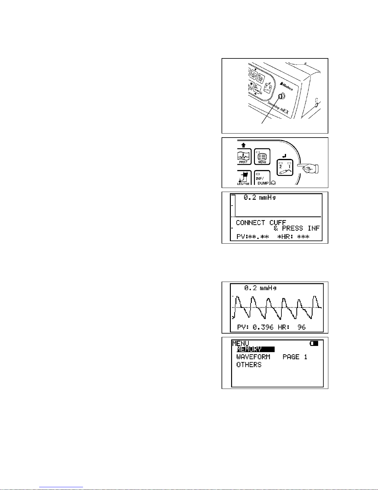
(3) Turn the unit on and press Probe Selection button
a few times until both #1 and #2 LEDs on the
button illuminate to go to PV-AC mode.
LCD will display as shown right below.
(4) Press INF/DUMP button to inflate the cuff up to 60
mmHg automatically.
Note: Press INF/DUMP button to stop the inflation and
dump cuff while inflation is in progress if desired.
The gain is automatically adjusted and the PV
waveform is shown on the LCD.
(5) When the waveform gets stable and rhythmic,
press INF/DUMP (Freeze) to freeze the waveform
and to dump the cuff.
Press PRINT button to print the waveform of last 5
sec, if necessary.
(6) If you wish to save the data on the memory, see Ҥ
4-2-7-a. MEMORY - STORE”.
(7) Remove the cuff and wrap it to the next site. Press INF/DUMP or probe button to
unfreeze waveform and repeat steps #5 to #7 for next site.
Inflation inlet
Page 24
17
3-9. Measuring Fetal Heart Rate
Evaluation of fetal heart rate and sounds throughout pregnancy except where fetal heart is
not developed sufficiently during the first trimester.
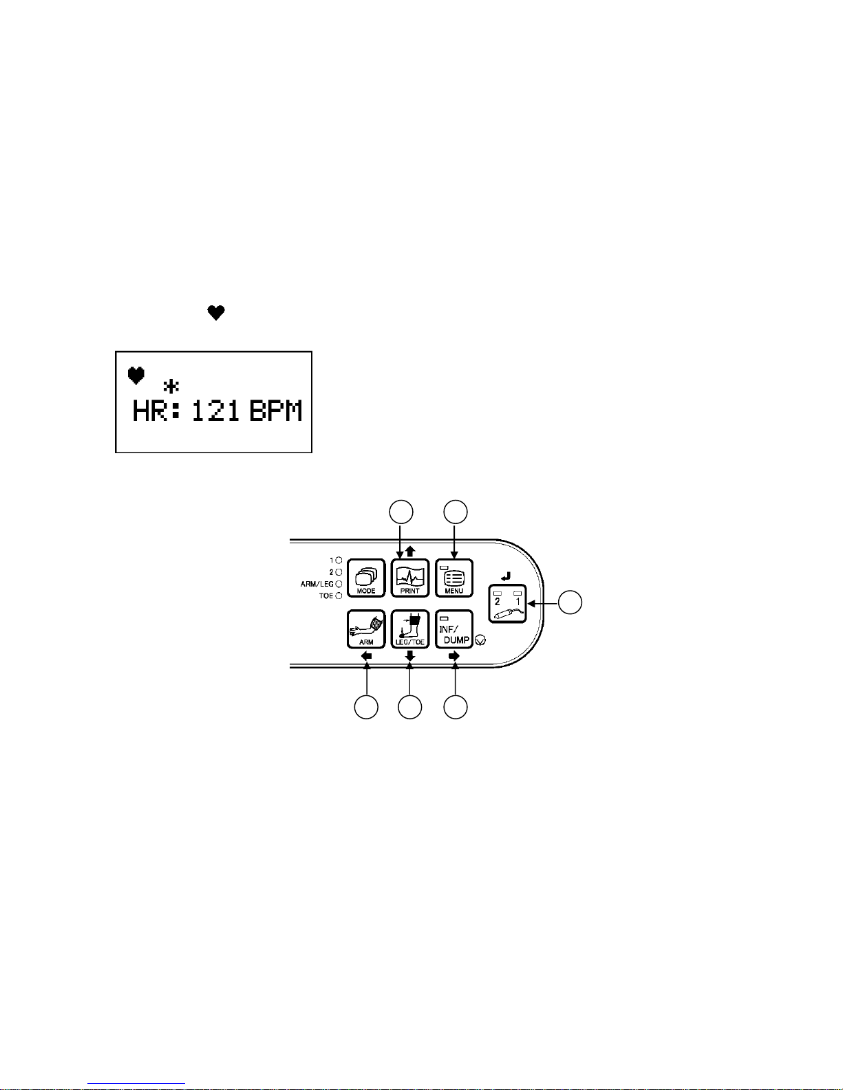
3-9-1. Functions
* Connect 2 MHz probe to the unit to go to fetal heart rate mode.
* The unit display heart rate calculated every 2 sec.
* Heart rate range is 30 to 240 BPM.
* Heart mark “ “tracks heart beat while in measurement.
* When calculated heart rate is not stable, the asterisk (*) will show above “HR”.
3-9-2. Operating panel
1. MENU: To go to menu mode.
2. Probe selection button: To select the probe intended to use from the connected
probes.
3. FREEZE / RIGHT: To freeze heart rate. Pressing probe button also freezes it.
To fix the mode or change the setting on menu mode.
4. UP / DOWN: To move the cursor up / down on menu mode.
5. LEFT: To get out of menu mode.
Other buttons are not available on fetal heart rate mode.
Note1: Fetal heart rate can’t be stored in memory and printed out.
Note2: Using with Smart-V-Link and Smart-Fetal-Link on connected computer are not available.
1
4
2 3 4
5
Page 25
18
3-9-3. OPERATION
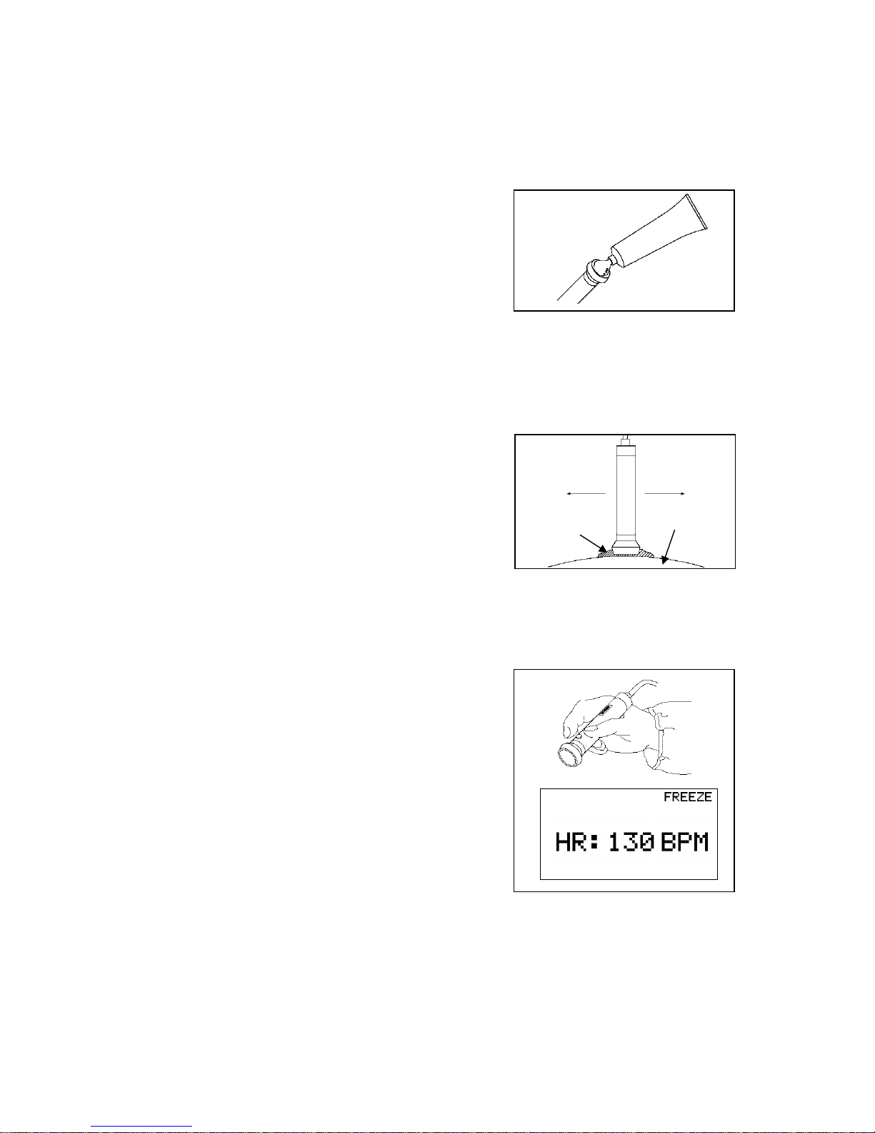
(1) Connect the probe to the probe connector.
See the step# (1) in the “§.3-1. Turning the unit ON” for the details.
(2) Put ultrasonic gel on the probe top or patient skin.
(3) Turn the unit on and sake sure the probe selection
LED illuminating corresponds to the connector you
connected probe. If not, press probe selection
button to change it.
(4) Put the probe on the middle of the abdomen at
right angle to the skin surface, and move it slowly
to locate the point where the maximum heart beat
Doppler sounds are heard.
Caution:
Verify the fetal heart rate. (Maternal heart sates
match the maternal pulse rates)
(5) When the heart rate becomes stable, press the
probe button or FREEZE button to freeze it.
Skin surface
Gel
Page 26
19
4. Mode settings
Note: For the mode and menu for PPG probe and PV probe, see “§ 7-3-4. Menu for PPG” and “§ 7-
4-3. Menu for PV”.
4-1-1. Basic Modes
Smartdop has following six Basic Modes:
1. Arterial Blood Velocity: Mode 1
2. Venous Blood Velocity: Mode 2
3. Arm and Leg Pressure: ARM/LEG
4. Toe Pressure: TOE
5. PV-Arterial: PV-AC
6. Menu: For other functions and settings
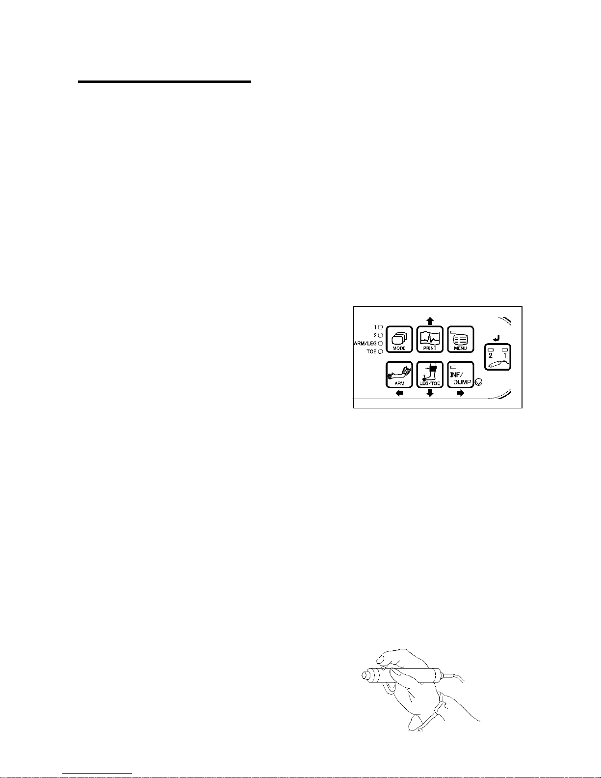
Pressing MODE button changes basic mode for mode
#1 through 4 and each mode LED selected will
illuminate. (Basic mode can be changed only when on
measurement mode.)
To go to PV-Arterial mode, press Probe Selection
button a few times until both LEDs on the button
illuminate. Press MENU button to go to menu mode
and MENU LED on the button will illuminate.
4-1-2. Measurement / Freeze Mode
Press Freeze button or probe button to freeze or unfreeze the waveform.
Measurement mode: For measurement (Unfreeze)
Freeze mode: For observing waveforms and numerical data
Note1: On Freeze mode, following waveforms are temporarily stored in the memory Freeze.
Mode 1: Waveform of the 5 sec before freezing
Mode 2: Waveform of the 25 sec before freezing
PV-AC: Waveform of the 5 sec before freezing
Note2: Pressing probe button also freezes and unfreezes
waveform. Probe button can be set for other function
upon PRB-KEY on menu mode.
Page 27
20
4-2. Menu mode
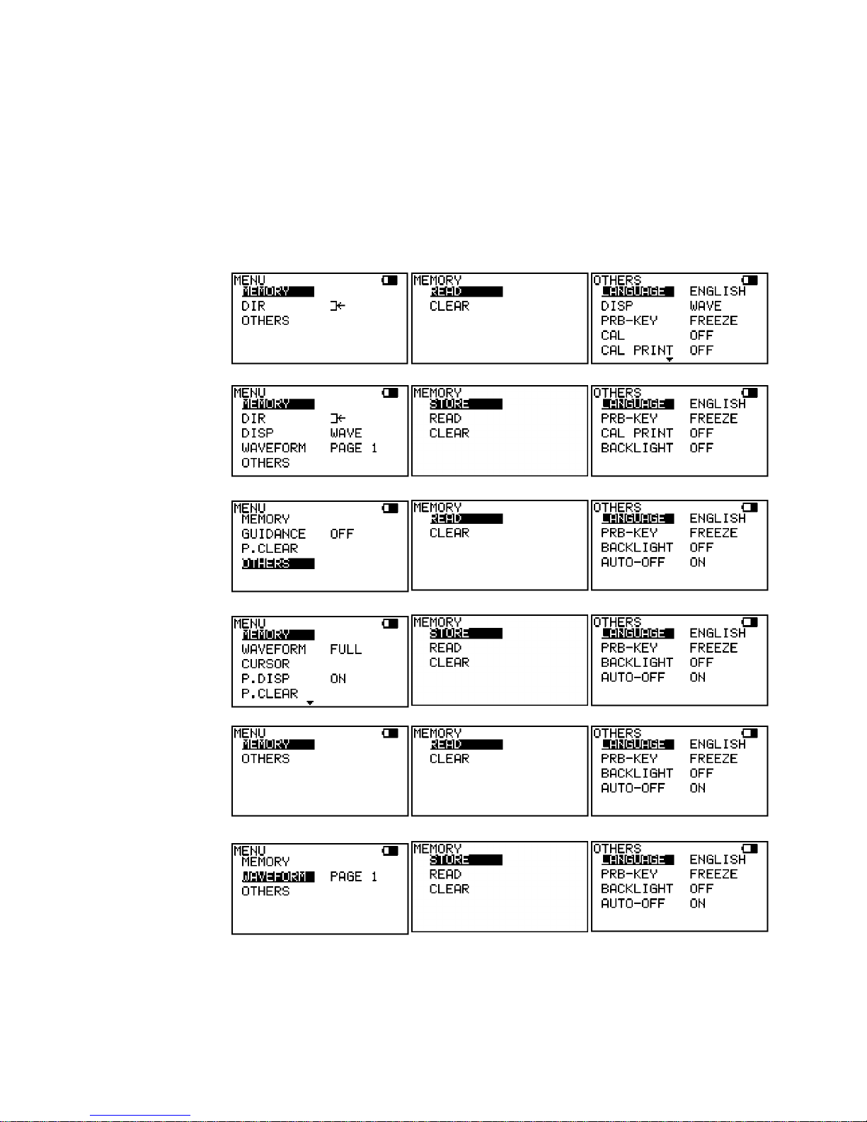
Various mode settings are changeable in Menu mode. Some menus have sub menus.
Refer to following Menus and Menu operation first.
4-2-1. Menus
Menu: Submenu:
Blood Velocity
measurement
mode
Blood Velocity
freeze mode
ARM/LEG/TOE
measurement
mode
ARM/LEG/TOE
freeze mode
PV AC
measurement
mode
PV AC freeze
mode
Page 28
21
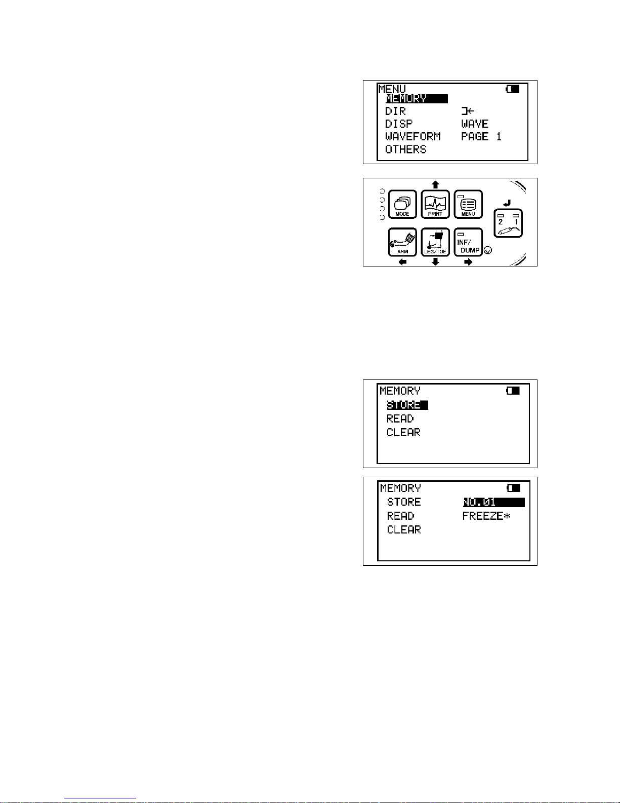
4-2-2. Menu Operation
(1) Press MENU button to go to Menu mode. The unit
will display the menu depending on Basic Mode.
(2) Select the menu by pressing Up (PRINT) or Down
(LEG/TOE) buttons and selected mode will be
highlighted. Press Right (INF/DUMP) button to
change the setting.
Note: On menu mode, some of the buttons on operation
panel work as cursor buttons as follows:
PRINT: Up
ARM: Left
LEG / TOE: Down
INF / DUMP: Right
Probe selection: Enter
(3) For MEMORY and OTHERS modes, press Enter
(or Right) to display sub menu and Up and Down to
select each sub menu.
(4) For MEMORY submenu, press Enter (or Right) to
show the memory number, and press Up and
Down to change the number.
(5) Press Left to go back to previous menu or press
MENU to get out of menu mode.
Page 29
22
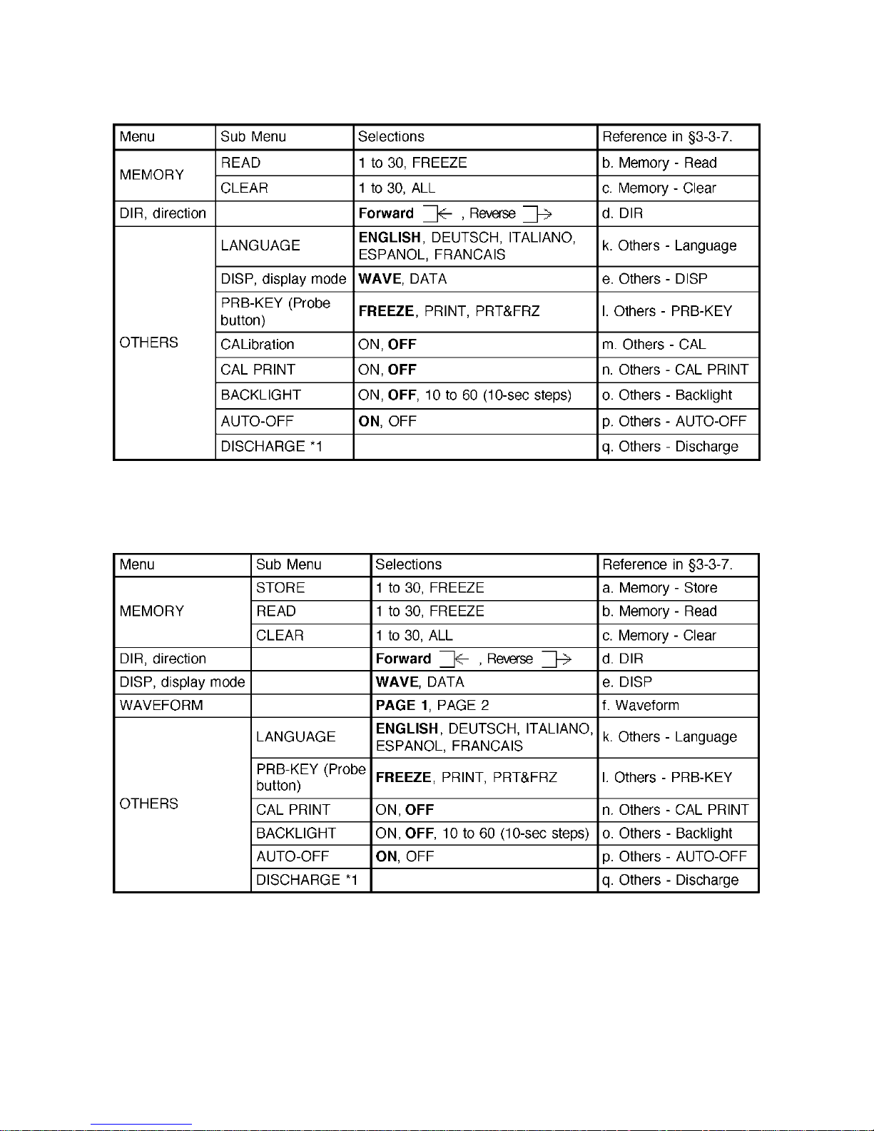
4-2-3. Menu for Blood Velocity Measurement Mode
Note: *1 DISCHARGE is available when AC adaptor is connected to the main unit.
4-2-4. Menu for Blood Velocity Freeze Mode
Note: *1 DISCHARGE is available when AC adaptor is connected to the main unit.
Page 30
23
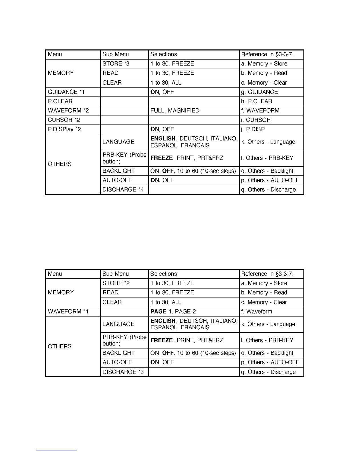
4-2-5. Menu for Pressure Mode
Note: *1 GUIDANCE is available only on Measurement mode.
*2 WAVEFORM, CURSOR and P.DISP are available only on Freeze mode.
*3 STORE is available only when on Freeze mode and pressure(s) has been assigned to ARM
or LEG/TOE.
*4 DISCHARGE is available when AC adaptor is connected to the main unit.
4-2-6. Menu for PV-AC Mode
Note: *1 WAVEFORM is available only on Freeze mode.
*2 STORE is available only on Freeze mode.
*3 DISCHARGE is available when AC adaptor is connected to the main unit.
Page 31
24
4-2-7. Menu Mode Details
See “§ 4-2-2. Menu Operation” how to show each menu item.
Do the mode setting once and subsequent Smartdop use will revert to this mode.
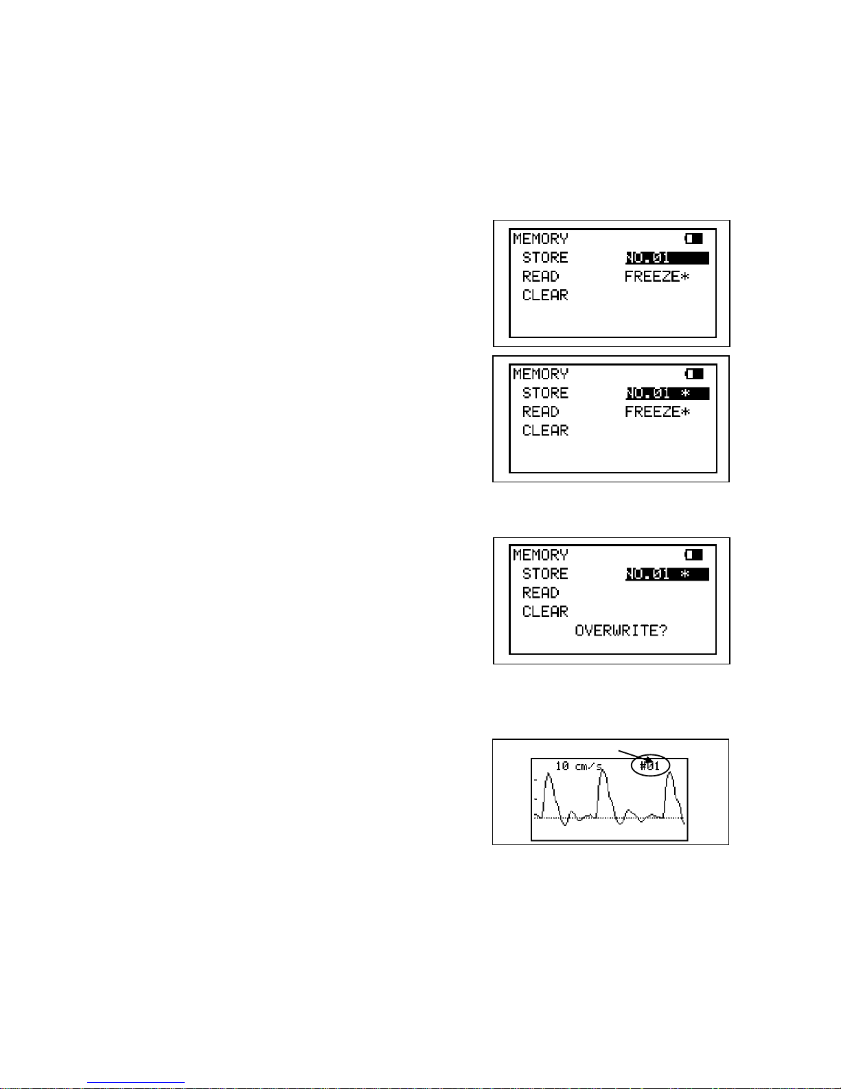
a. MEMORY - STORE
(1) STORE sub menu is available when on freeze
mode only.
Press Enter (or Right) on STORE sub menu and
the first memory number available will be shown
automatically on STORE sub menu. If necessary,
change the number where to store waveform data
by pressing Up and Down.
Note: The memory number with "*" indicates memory area
where other data have been already stored.
(2) Press Enter to store the data into the memory and
it will go back to waveform display automatically.
Note: If other data have been already stored in memory
number storing, a confirmation of "OVERWRITE?"
will be shown. Press Enter to overwrite, or press any
one of cursor buttons to cancel for selecting other
memory number available. STORE sub menu is not
available if pressure has not been assigned to ARM
or LEG/TOE.
b. MEMORY - READ
(1) Select the memory number where to read
waveform data from by pressing Up and Down.
(2) Press Enter button to show the waveform.
If desired, press Enter again or MODE + Enter to
show next or previous waveform stored,
respectively.
Note: Any frozen waveform is stored temporarily in memory area of FREEZE separated from
regular 30 memories. It can be re-shown by reading from memory FREEZE and won't be
erased until next waveform is frozen or unit is turned off.
Memory number
Page 32
25
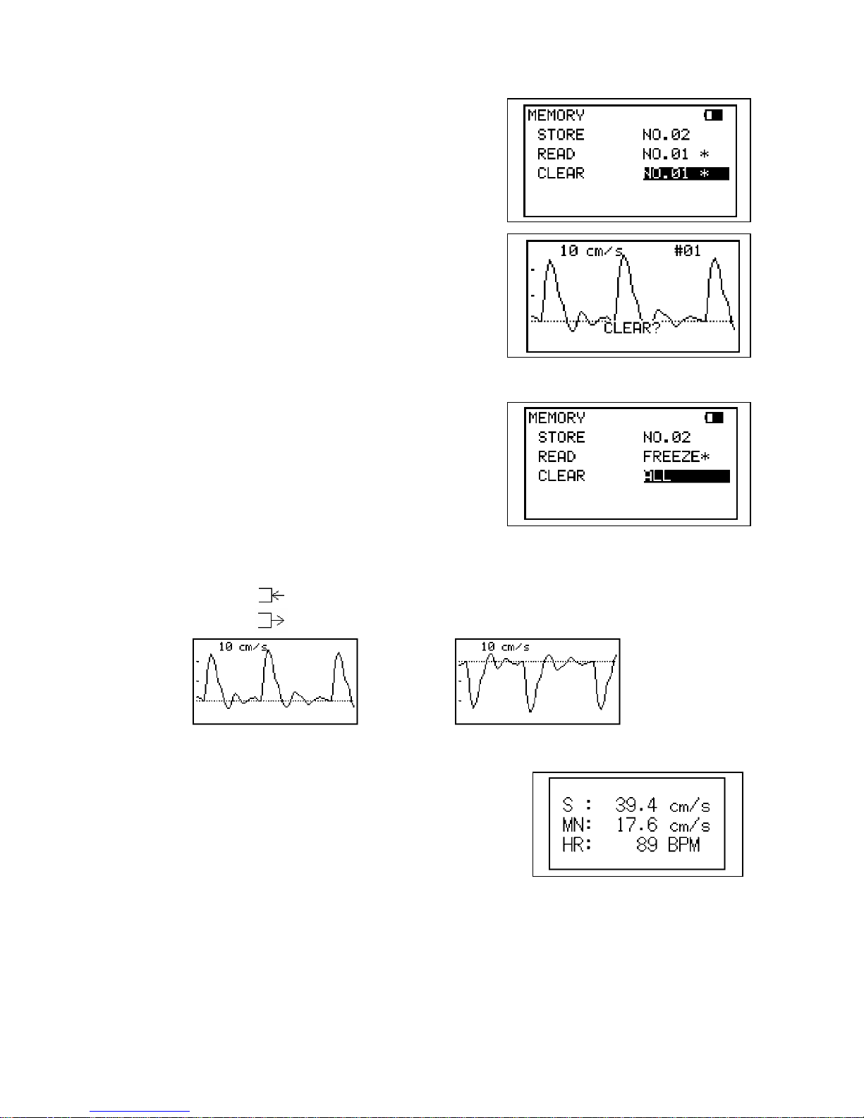
c. MEMORY - CLEAR
(1) Select the memory number, in which you wish to
clear the data. The memory number with "*"
indicates memory area where data have been
already stored.
(2) Press Enter and then the confirmation screen with
waveform stored will be displayed as shown in the
picture right. Press Enter to clear the data, or press
Left to cancel.
Note: If the waveform selected is not the one you wish to
clear, press Up and Down to select other memory #.
(3) To clear all the data at once except FREEZE,
select and press on ALL and follow the instruction.
d. DIR (Flow direction)
Press Right to change waveform polarity as follows:
Forward: Flow toward probe is processed as positive component.
Reverse: Flow away from probe is processed as positive component.
e. DISP / OTHERS - DISP (Waveform / Data)
Press Right to change the Display mode as follows:
WAVE: Displays waveforms.
DATA: Displays numerical data
Note: Changing Display mode can be also done by pressing LEG/TOE.
Forward
Reverse
Page 33
26
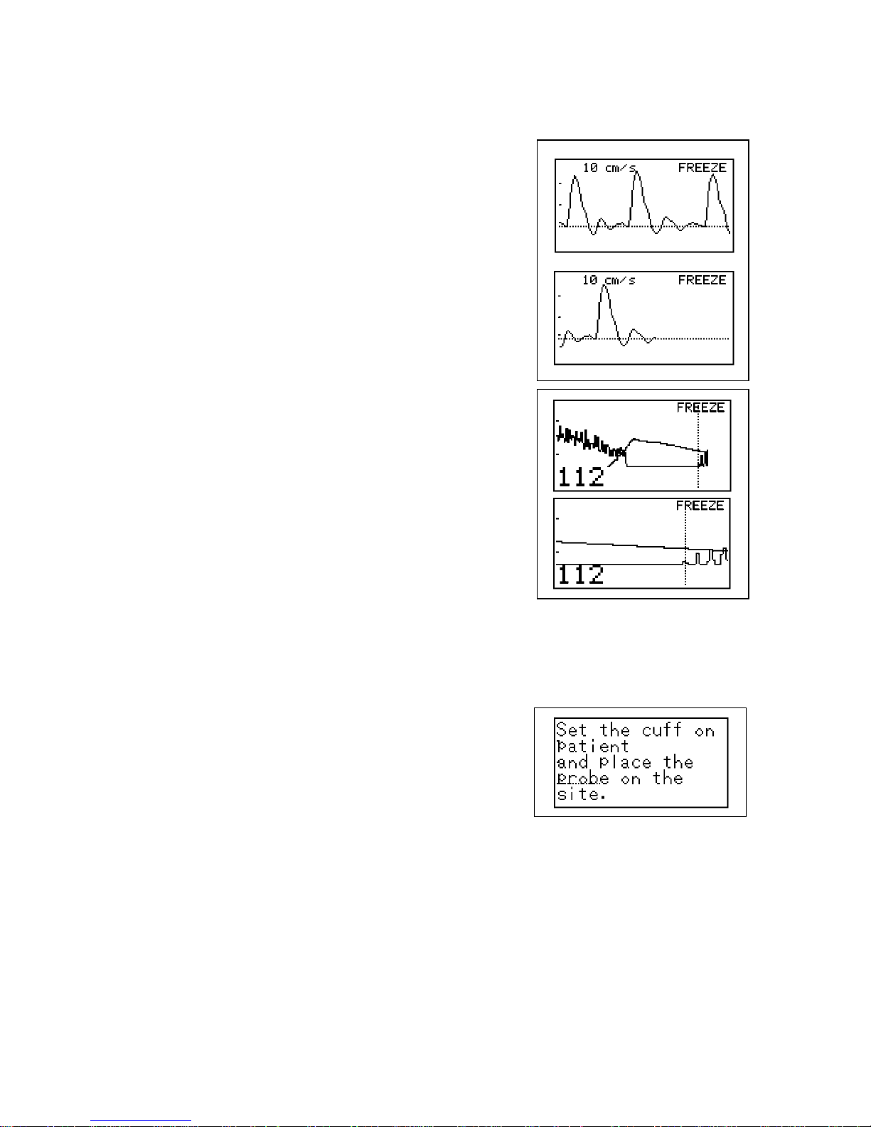
f. WAVEFORM (Freeze mode only)
Blood velocity and PV Arterial modes (Changing viewing area of waveform);
Press Right to change viewing area of waveform.
Page 1: First half of waveform
Page 2: Second half of waveform
Note: The pages can be also switched by pressing a shortcut
key of MODE when on freeze mode of velocity and
PV arterial.
ARM/LEG and TOE pressure mode;
(Magnifying/ demagnifying viewing area of waveform)
Press Right to change viewing area of waveform.
FULL: Full waveform is displayed on LCD
MAGNIFIED: Magnified waveform where systolic
pressure has been determined is
displayed on LCD.
Note: FULL/MAGNIFIED mode can be also changed by pressing a key combination of
MODE + Down when on pressure freeze mode.
g. GUIDANCE
This setting enables or disables the function of
displaying guidance on the LCD while on ARM/LEG
and Toe pressure modes.
Press Enter or Right to change the guidance mode;
ON: Displays guidance
OFF: Not display guidance
Note: GUIDANCE mode can be changed only when on
measurement mode.
Page 1
Page 2
Page 34
27
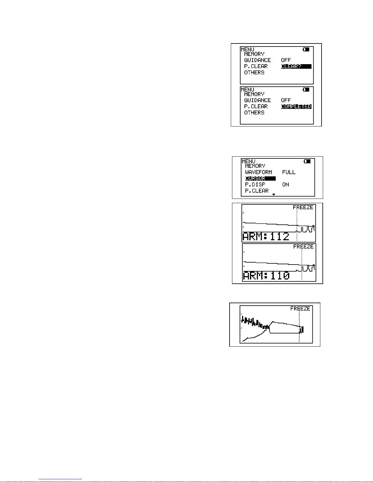
h. P.CLEAR (Clearing blood Pressure data)
(1) Press Enter and a confirmation of “CLEAR?” will
be shown.
(2) Press Enter again to clear the pressure data in
RAM and “COMPLETED” will be shown for 5 sec.
Note: This function can be also done by turning unit off and
on OR pressing a shortcut key of ARM or LEG/TOE
longer than 2 sec.
i. CURSOR (Mode for adjusting systolic pressure point)
(1) Press Enter to go to Cursor mode.
(2) Press Right / Left to move cursor to the right and
the left for locating the true systolic pressure point.
(3) Press Enter to fix it or press Menu to cancel.
Note: Adjusting systolic point can be also done by pressing
a key combination of MODE + Right / Left.
j. P.DISP (Displaying/erasing Pressure value)
Press Enter (or Right) to display pressure waveform
WITH or WITHOUT pressure value(s).
Note: The Pressure Display mode can be also switched by
pressing a shortcut key of MODE.
k. OTHERS - LANGUAGE
Press Enter or Right to select the language desired in which menus and messages are
written.
Languages: English, Deutsch, Italiano, Español, Français
Without pressure value(s)
Page 35
28
l. OTHERS - PRB-KEY (Probe button function)
Press Enter or Right to change the probe button function.
FREEZE: Freezes/unfreezes waveform
PRINT: Activates/deactivates printer
FRZ&PRINT: Freeze and Print
Note: When on ARM/LEG and TOE modes, probe button works the same way as INF/DUMP
button no matter what is selected on the PRB-KEY mode.
m. OTHERS - CALibration
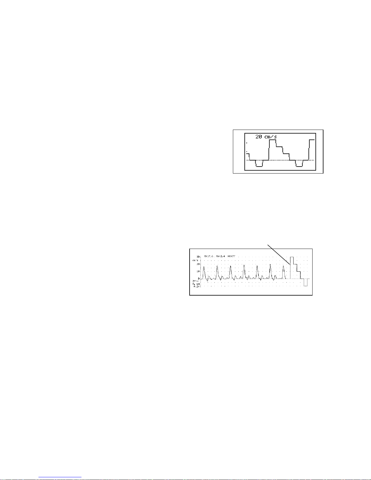
Press Enter or Right to change the mode.
ON: Displays 4 step (3, 2, 1, 0, - 1kHz)
calibration waveform on the LCD.
OFF: Measurement mode
n. OTHERS - CAL PRINT (Printing Calibration)
Press Enter or Right to change the mode.
ON: Prints 4 step (3, 2, 1, 0, - 1kHz) calibration after velocity waveform
on the chart.
OFF: Prints no calibration waveform.
o. OTHERS - BACKLIGHT
LCD backlighting time can be adjusted on BACKLIGHT setting and the longer time
gives you shorter battery life.
Press Up and Down to select the time and press Enter to fix it.
ON: Turns backlight always on.
OFF: Turns backlight always off.
10 ... 60: Auto-off time with 10 sec steps
Note: BACKLIGHT ON / OFF can be also done by pressing a key combination of MODE +
MENU.
When on the Auto-Off mode, backlight goes off if unit is left with no operation for more than
auto-off time and next any button operation will turn the light on as well as doing function
associated with the button however, light is always on while on measurement mode.
4 Step Calibration
Page 36
29
p. OTHERS - AUTO-OFF (Automatic shut-off)
Press Enter or Right to change the mode.
ON: Enables Automatic shut-off.
OFF: Disables Automatic shut-off.
See “§ 3-1. Turning the Unit On” for the details.
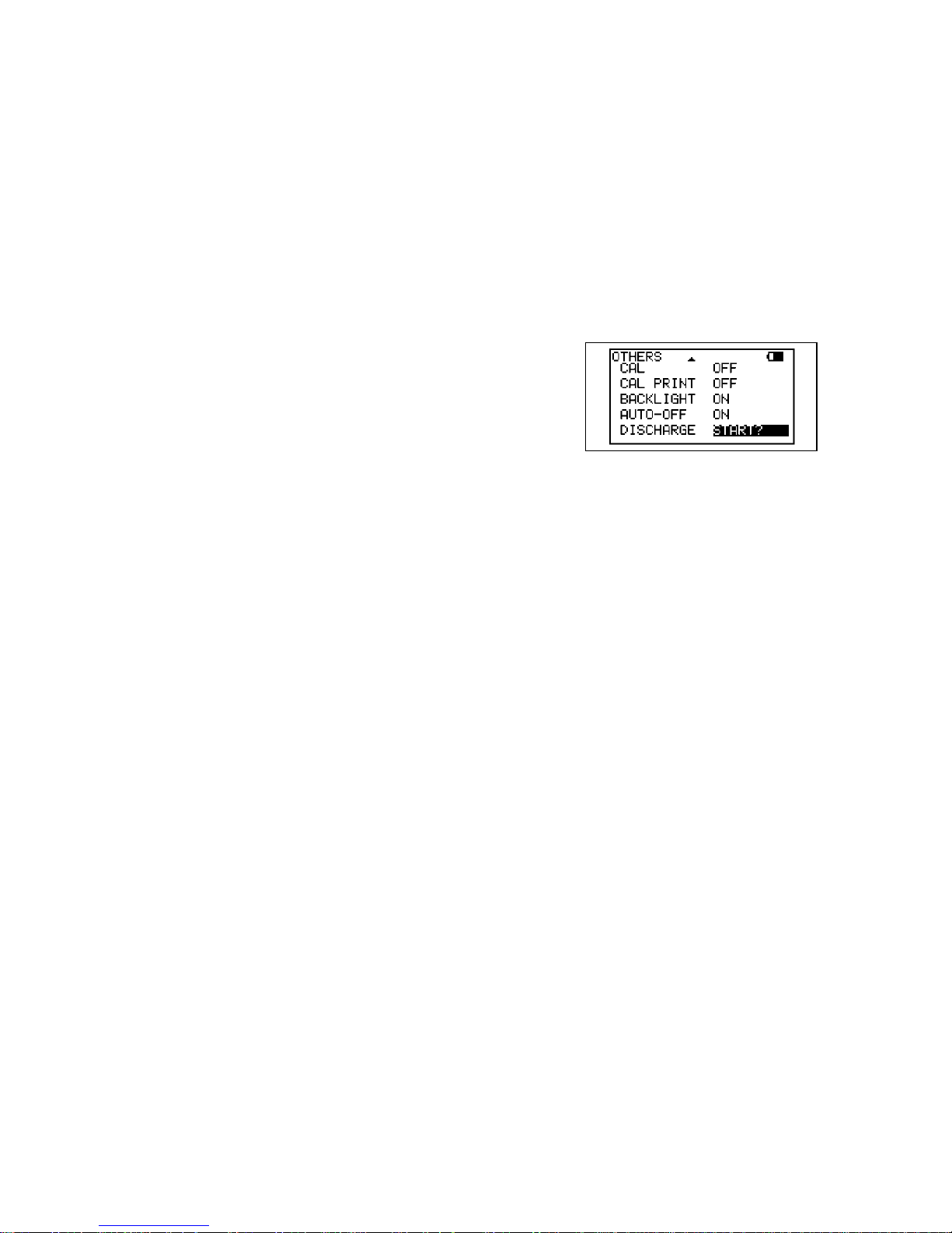
q. OTHERS - DISCHARGE
DISCHARGE is available when AC adaptor is connected to Smartdop.
(1) Press Enter and confirmation “START?” will be
shown.
(2) Press Enter again to start discharging and then
charging.
Note: It takes a few extra hours to fully discharge a fully charged battery prior to full charging
hours.
Page 37
30
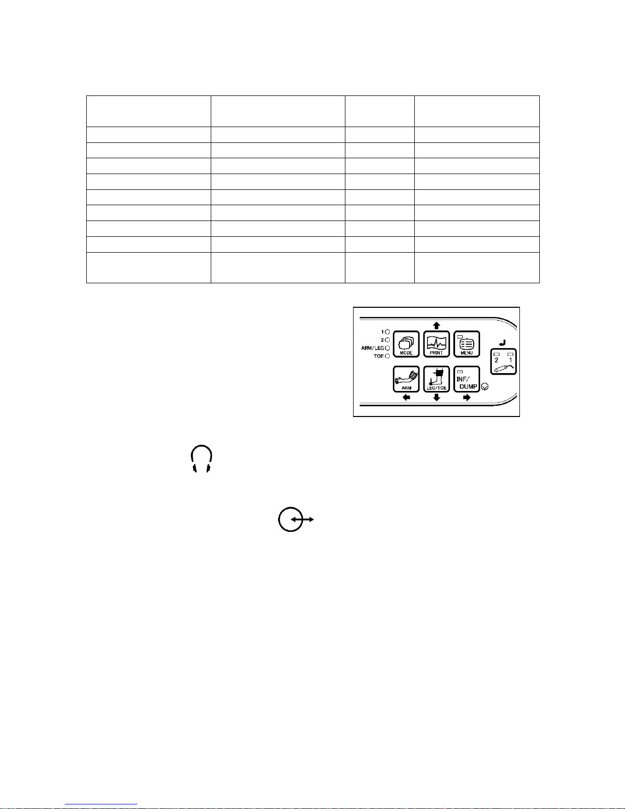
4-3. Shortcut keys
Note: “MODE +” means to press and hold MODE button before pressing 2nd combination button.
4-4. External outputs
4-4-1. Headset
Connect the headset when necessary. The headset cuts off the speaker.
4-4-2. Communication Port
To observe the waveform in high resolution on a PC monitor or to store the waveform and
numerical data into a computer for future reference as well as a report of standardized
testing modules.
(1) Install the communication software Smart-V-Link, option, on your computer.
(2) Connect Smartdop to the computer with dedicated communication cable that comes
with Smart-V-Link.
(3) Turn the unit on and start Smart-V-Link on your computer.
Note: Refer to the operating manual for Smart-V-Link for details.
Shortcut keys
Functions
Modes
Reference
in § 4-2-7
MODE + MENU
Backlight On / Off
All modes
o. Others - Backlight
MODE + RIGHT
Right Cursor
Pressure
i. Cursor
MODE + LEFT
Left Cursor
Pressure
i. Cursor
MODE + DOWN
Zoom In / Out
Pressure
f. Waveform
ENTER
Next waveform
Freeze
b. Memory - Read
MODE + ENTER
Previous waveform
Freeze
b. Memory - Read
ARM / LEG long press
BP clear
Pressure
h. P. Clear
MODE
BP display On / Off
Pressure
j. P.DISP
MODE
Change Page 1/2 or 2/2
Velocity &
PV - AC
f. Waveform
Page 38
31
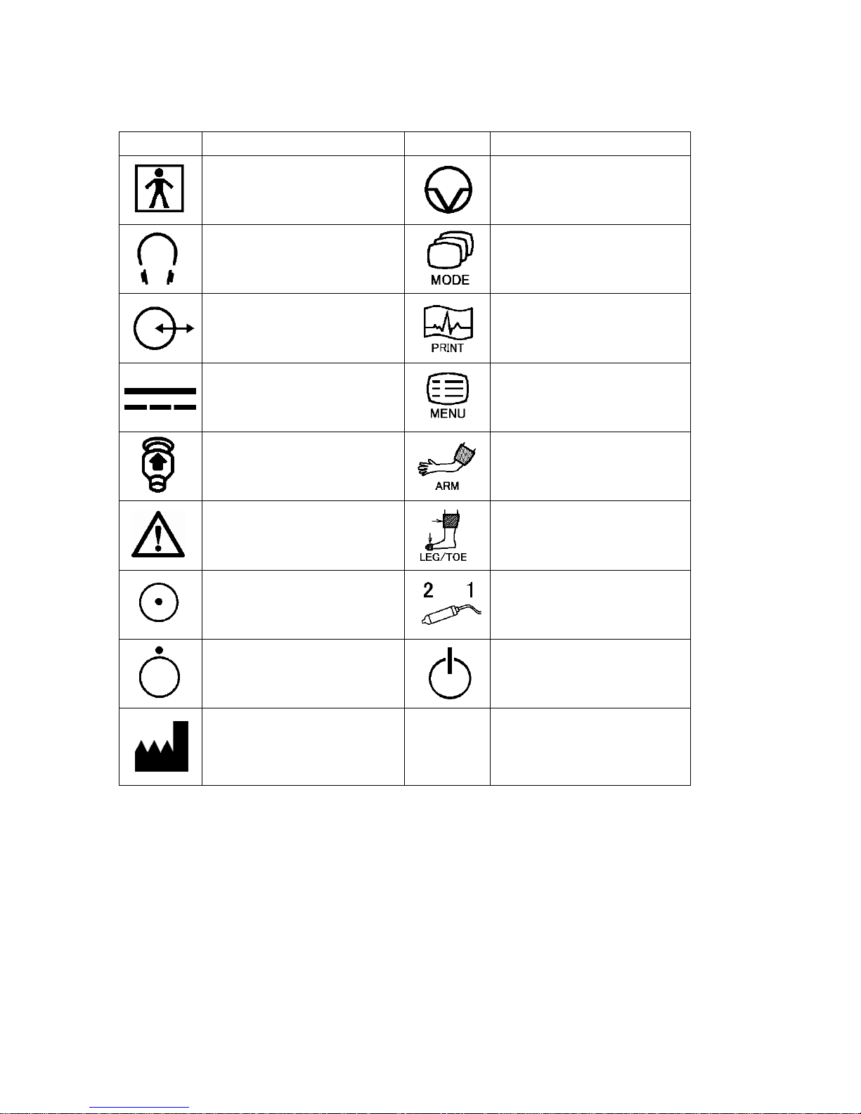
4-5. Symbol list
Symbol
Description
Symbol
Description
Type BF applied part
Freeze
Headset
Mode button
USB connector
Print button
AC adaptor connector
Menu button
Probe connector
Arm button
Caution*
Refer to the Operating
manual
Leg / Toe button
Power ON
Probe selection button
Power OFF
Probe button
Manufacturer
Note: * Caution must be observed to avoid damage to the unit. Refer the operating
manual carefully.
Page 39
32
5. Display and Printing
5-1. Arterial and venous blood velocity modes
Arterial and venous blood velocity can be measured on these modes by Doppler
technique. Smartdop displays and prints waveform as follows:
Mode 1:
Displays approx. 2.56 sec of waveform per screen of LCD
Prints waveform in time scale of approx. 25 mm/sec.
Forward and reverse components are combined.
Mode 2:
Displays approx. 12.8 sec of waveforms per screen of LCD
Prints waveforms in time scale of approx. 5 mm/sec.
Forward component (arterial) is separated from reverse component (venous).
For typical operation for blood velocity modes, see “§ 3-5. Measuring Blood Velocity”.
5-1-1. Waveforms on LCD
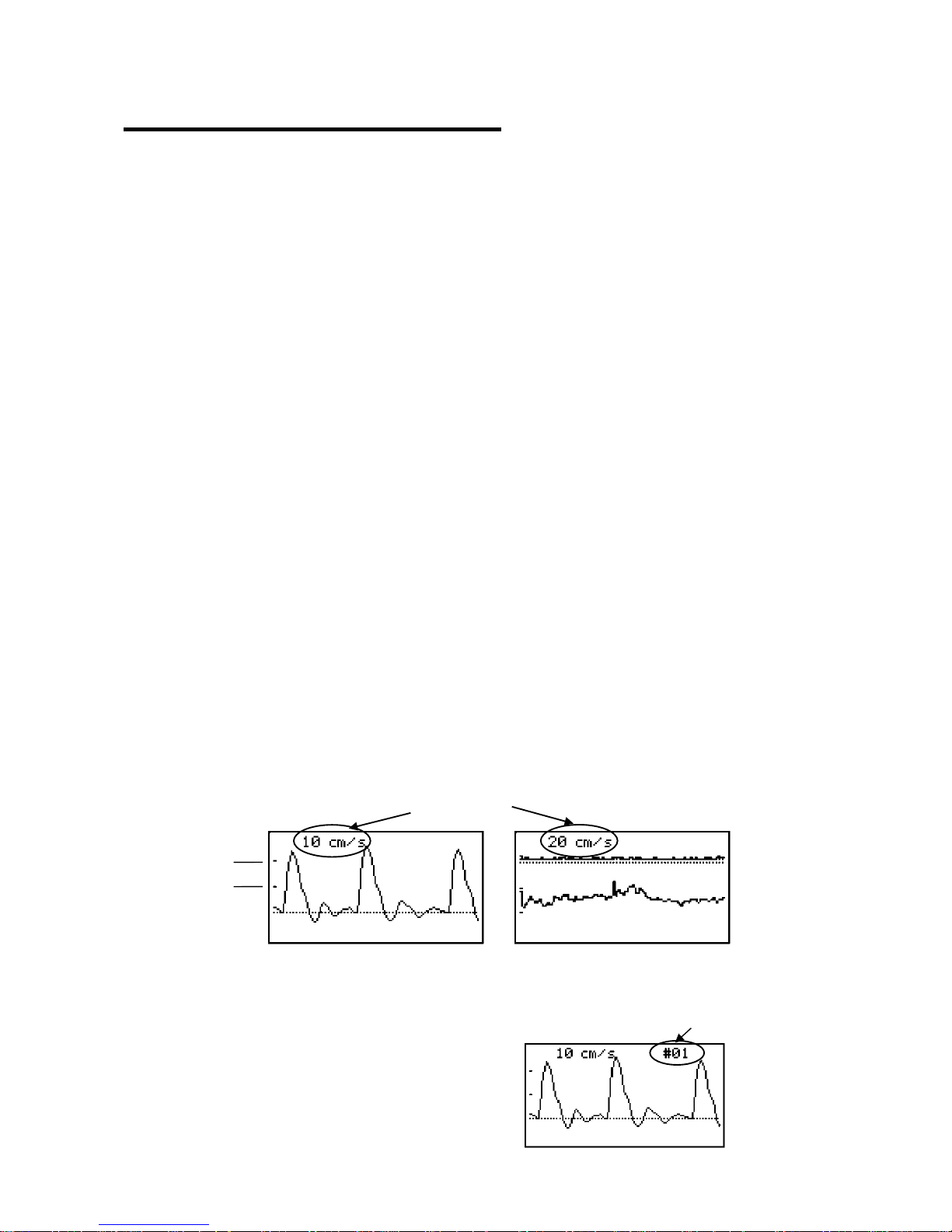
The base line is automatically located at best position depending on how big the
reverse component is. Smartdop has 4 base lines, the bottom, 1/4 from the bottom, the
center, and 3/4 from the bottom.
The waveform amplitude is automatically adjusted for optimal observation.
The velocity amplitude scale per division is shown at top left of LCD.
Memory number is shown at top right of LCD for waveform read on MEMORY mode.
e.g. "#01"
Memory number
Amplitude
Division
Mode 1
Mode 2
Page 40

33
5-1-2. Parameters
Mode 1: Abbrs.
Systolic velocity [cm/s] S
Mean velocity [cm/s] MN
Heart rate [BPM] HR
Mode 2: Abbrs.
Systolic velocity [cm/s] S
Mean velocity [cm/s] MN
Note: All computations are based on as follows:
Mode1: Latest 3 beat average on measurement mode
First 3 beat average on freeze mode
Mode2: Latest 10 sec average on measurement mode
First 10 sec average on freeze mode
If the heart rate can't be calculated because of an over +/-25% irregularity due to an
Arrhythmia or venous waveform, "HR:***" will be printed out as an error indicator.
5-1-3. Printing Waveform and Numerical Data
(1) Press PRINT button to print waveforms.
Also, pressing probe button controls printer when PRB-KEY in the menu is set for
PRINT or FRZ&PRINT mode.
(2) Smartdop prints waveforms and numerical data as follows and then stops printing
automatically.
Measurement mode
Mode 1: Waveform of the last 5 sec before pressing PRINT button
Mode 2: Waveform of the last 25 sec before pressing PRINT button
Freeze mode
Mode 1: Waveform of the last 5 sec before freezing
Mode 2: Waveform of the last 25 sec before freezing
(3) If necessary, press PRINT button the second time to deactivate printer while the
printing is in progress.
Page 41
34
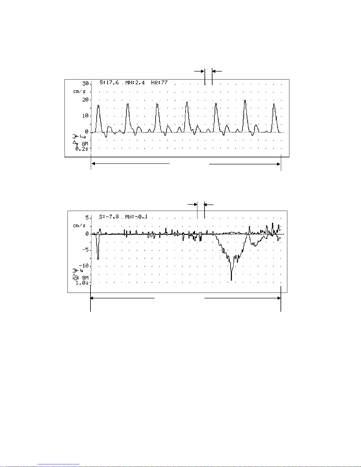
5-1-4. Print Samples
Mode 1 (Artery): *Time scale 0.2 sec/div. (approx. 25 mm/sec)
Mode 2 (Vein): *Time scale 1 sec/div. (approx. 5 mm/sec)
0.2 sec
5 sec max.
1 sec
25 sec max.
Page 42
35
5-2. ARM / LEG and TOE pressure modes
Systolic blood pressures of Arm, Leg and Toe can be measured automatically on these
modes and displayed them with velocity/pressure documentation.
Also, Smartdop calculates ABI / TBI and prints them.
For typical operation for Pressure modes, see “§ 3-6. Ankle brachial pressure index (ABI)”
and “§ 3-7. Toe brachial pressure index (TBI)”.
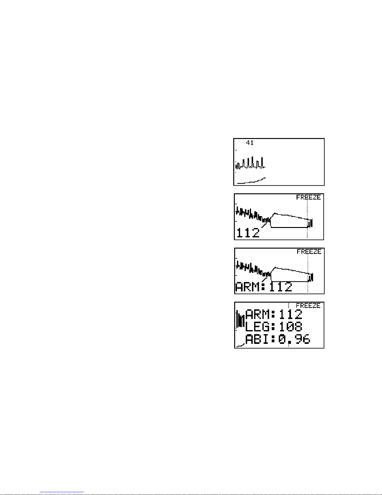
5-2-1. Display Samples in Pressure Measurement Process
(1) During measurement for blood pressure of arm
(2) End of the measurement for arm pressure (Freeze
mode)
(3) After pressing ARM button
(4) After measurement of leg pressure and pressing
LEG button
5-2-2. Optional Functions
Press ARM or LEG/TOE button to recalculate ABI/TBI for the 2 stored pressure data read
from the memory.
Page 43
36
5-2-3. Error Messages
When error occurs while measuring blood pressure, the following error messages will be
displayed on the LCD:
E1: (Reserved)
E2: Waveform error.
E3: Pressure exceed 300 mmHg.
E4: Systolic pressure not found.
E5: Time out.
E6: Cuff pressure don’t go up.
E7: Cuff pressure don’t go down
E9: Cuff pressure go up very fast
Press any button other than probe selection button to delete the error message and
proceed to next step.
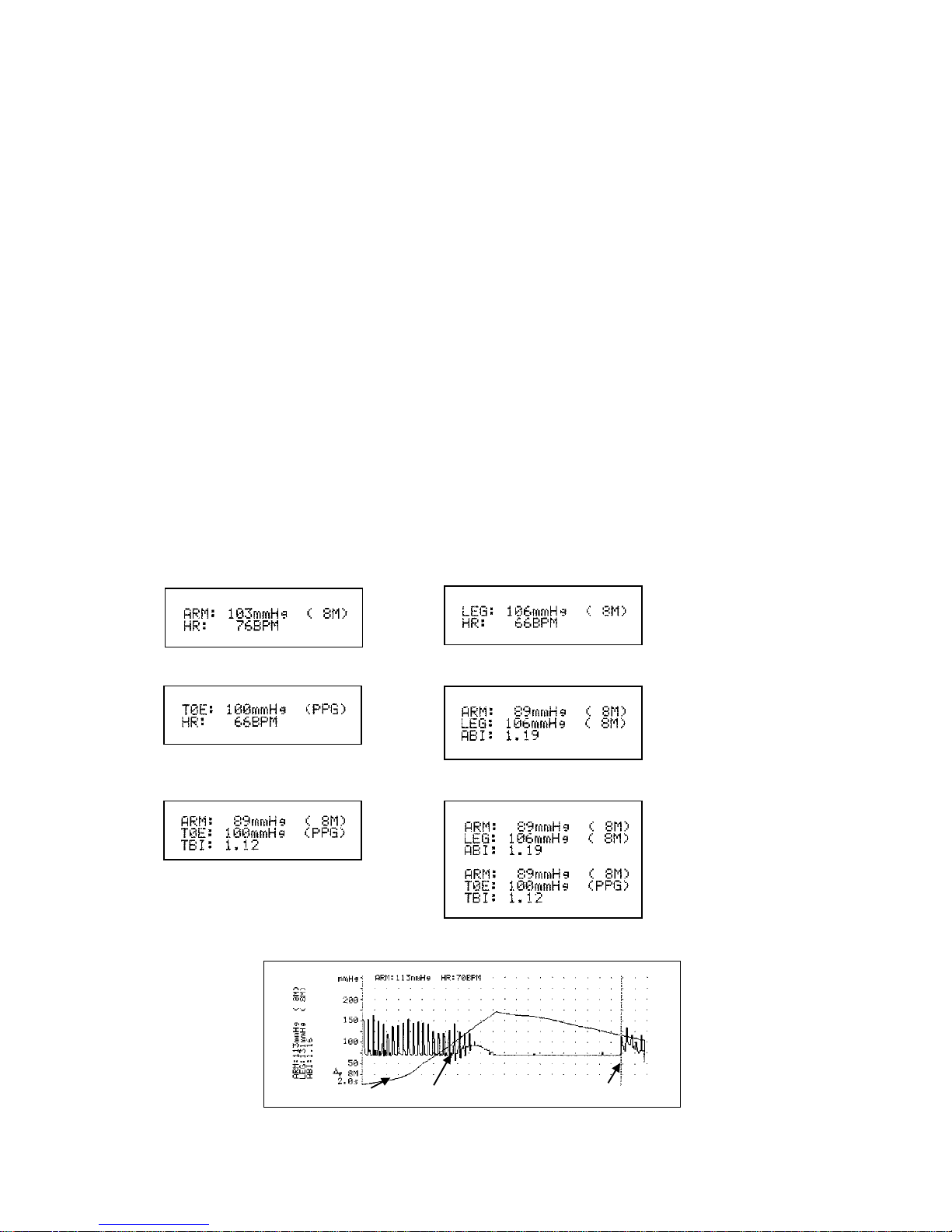
5-2-4. Print Samples
(1) Pressing PRINT button less than 1 sec.
(2) Pressing PRINT button longer than 2 sec.
ARM only
LEG only
TOE only
ARM and LEG
ARM and TOE
Arm, Leg and Toe (Arm should be saved at the end.)
Pressure
Velocity
Sound reappearance
Page 44
37
5-3. PV arterial mode (PV-AC)
PV Arterial Studies (PV-AC mode) can be performed on this mode without any optional
probes. (PV-DC needs optional PV probe.)
Smartdop displays and prints waveform as follows:
Displays approx. 2.56 sec of waveform per screen of LCD
Prints waveform in time scale of approx. 25 mm/sec.
For typical operation for PV-AC mode, see “§ 3-8. PV - Arterial Studies”.
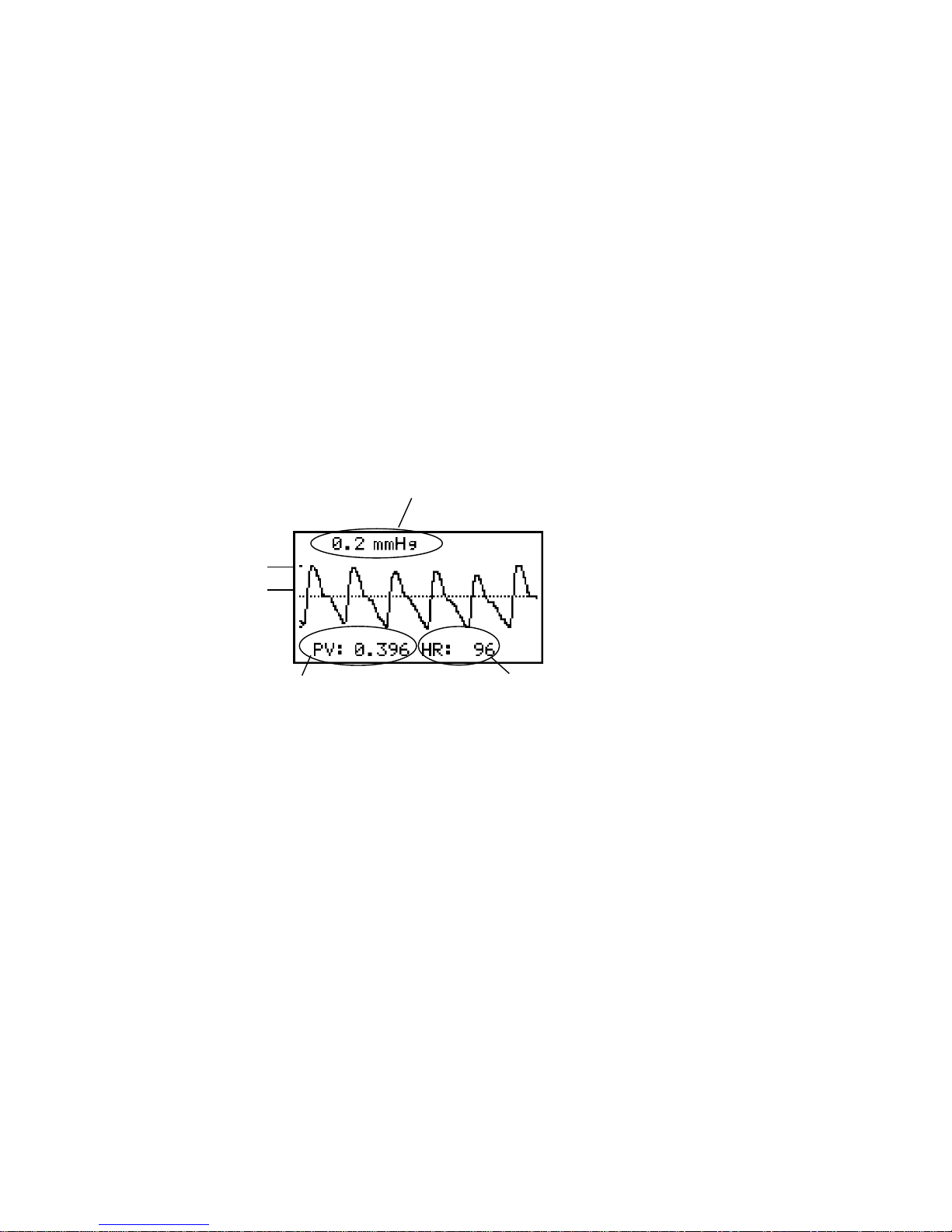
5-3-1. Waveforms on LCD
The waveform amplitude is automatically adjusted for optimal observation.
The pressure amplitude scale per division is shown at top left of LCD.
Pulse volume amplitude and heart rate are shown at bottom of LCD.
Amplitude scale
Pulse volume amplitude
Heart rate
Division
Page 45

38
6. Maintenance
6-1. Performance check by user
Please perform the maintenance in case the unit is not in use for a while.
Preparation
(1) Make sure if there is no damage and / or crack on the main unit and probe.
(2) Check if wall voltage is good for rating input voltage of AC adaptor.
(3) Turn the unit off.
(4) Connect AC adaptor to the unit.
(5) Connect the probe, suitable for intended clinical application, to the unit.
Checking
(1) Connect AC adaptor.
(2) Turn the unit on.
(3) Check if LCD works properly.
(4) Set printing paper to the unit and check if it prints waveform properly.
(5) Rub the probe tip and check if sounds come out from speaker and LCD shows the
waveform.
(6) Check if sound volume can be adjusted.
(7) Check if battery level is sufficient for battery operation.
6-2. Cleaning
Probe
Remove the Doppler gel from the probe head after use.
Clean the probe using damp cloth and then wipe with a soft dry cloth, but take great care
that any water may not penetrate into the probe.
If using disinfectant, consult in advance with the manufacturer.
Main unit
To clean the main unit, use a damp cloth and then wipe with a soft dry cloth, but take great
care that any water may not penetrate into the unit. Check the unit by maintenance
procedures mentioned in “6-1. § Performance check by user”.
Blood pressure cuffs
The cuffs are intended for use only on intact skin. To clean, wipe away any dirt or stain
using alcohol.
Page 46
39
6-3. Warranty
The guarantee period is two years for this equipment and one year for probe after the date
of purchase when used under normal conditions.
In the event of a problem during the warranty period, please contact your dealer.
In case the warranty period is over, please consult your dealer for a charged service.
7. Options
7-1. Probe selection:
The frequency of diagnostic ultrasound is inversely proportional to depth of penetration.
Use those probes depending on your applications.
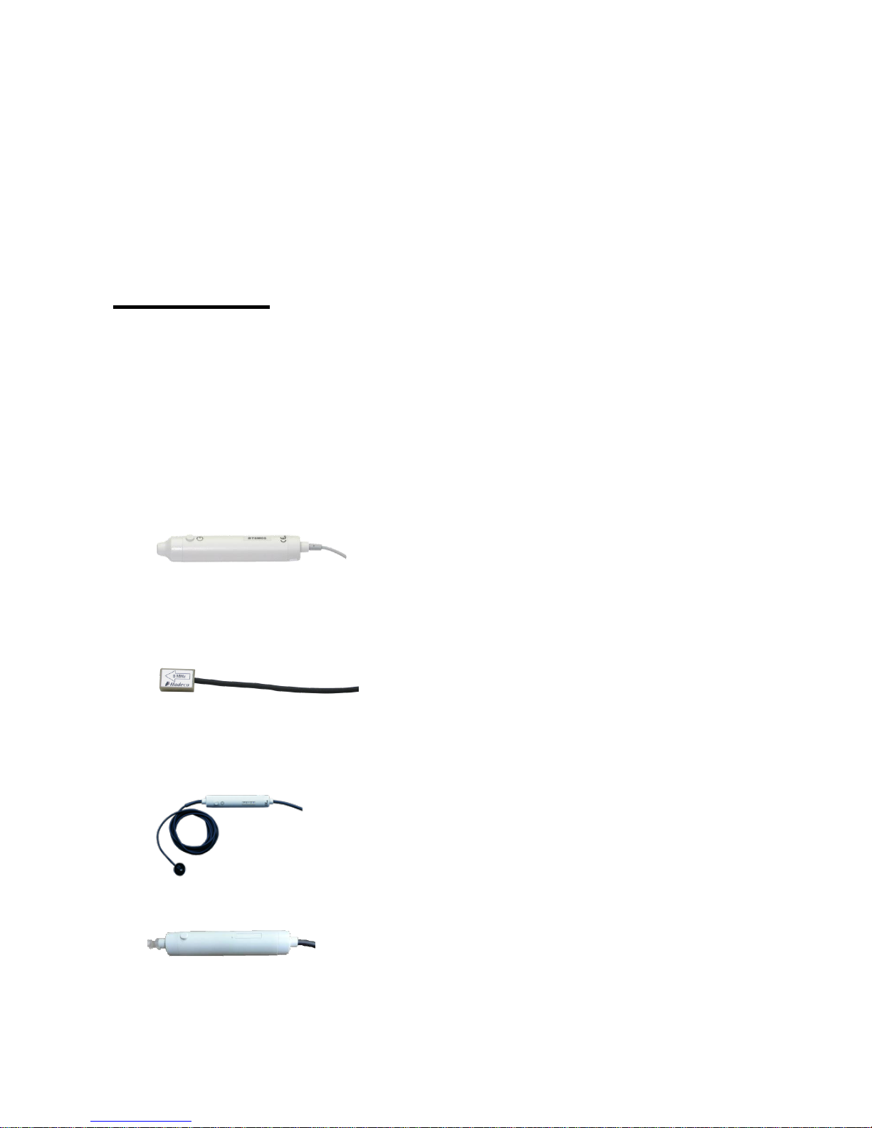
Standard Doppler probe:
Standard:
2MHz: BT2M20S8C(A)*
4MHz: BT4M05S8C(A)*
5MHz: BT5M05S8C(A)*
8MHz: BT8M05S8C(A)*
10MHz: BT10M5S8C(A)*
Flat:
8MHz: BF8M15S8A
* The end word “C” indicates curl type cable, “A” indicates straight type cable.
PPG probe: PG-21
PV probe: PV-21
Page 47

40
7-2. Others:
Sphygmomanometer
3-way stopcock
Smart-V-Link software with communication cable
Cuffs: DVC-1.9, DPC-2.5, VC-10, VC-12
PPG probe clip
7-3. Photoplethysmograph
With the PG-21, Smartdop senses the reflection of light from the hemoglobin of the red
blood cells in surface vessels by utilizing infrared light.
“How to use photoplethysmograph” is described in this section.
7-3-1. PPG (Photoplethysmography) Probe Assemblies
Model PG-21
AC Coupling: Arterial pulse waveform studies, Toe pressure
DC Coupling: Venous reflux study
7-3-2. PPG - Arterial Pulse Waveform Studies
Purpose
Arterial pulse waveform studies by photoplethysmography are performed to determine the
presence or absence of pulsatile flow and to assess the state of perfusion in the tissue
area immediately beneath the sensor site. When used with a suitable cuff and manometer,
the method permits the measurement of systolic blood pressure in the fingers and toes.
To the main unit
Probe
PPG probe
Page 48
41
Preparation
(1) Connect the PPG probe assembly to the probe connector #1 or #2.
(2) Make sure Mode 1 LED (AC mode) illuminates. If
not, press MODE button to select Mode 1 for AC
mode.
(3) Check that the face of the PPG sensor is free of
stains. Clean it if necessary.
(4) Make certain that room temperature is comfortable and, especially, that the skin
surface where the probe is to be mounted is warm. Cold constricts superficial blood
vessels and thus jeopardizes the accuracy of PPG measurements.
Examination Procedure
(1) Apply the sensor with the clear side against the skin surface, and fix it in place using
Velcro strap or double-sided clear tape or PPG probe clip (Option).
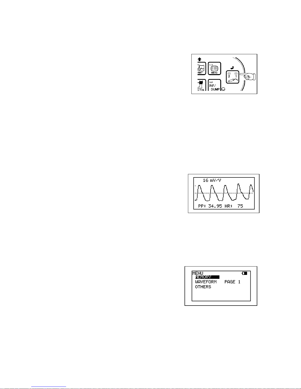
(2) The gain is automatically adjusted and the PPG
waveform is shown on the LCD.
(3) When the waveform gets stable and rhythmic,
press INF/DUMP or probe button* to freeze the
waveform.
Press PRINT button to print the waveform of last 5
sec., if necessary.
Note: *When PRB-KEY is on Freeze mode.
(4) If you wish to save the data on the memory, see
“§ 4-2-7-a. MEMORY - STORE”.
7-3-3. PPG - Venous Reflux Study
Purpose
The venous reflux study is performed to assess valvular competence by measuring the
amount of time required for venous refilling after calf veins have been emptied through
exercise.
Page 49
42
Preparation
(1) Connect the PPG probe assembly to the probe connector #1 or #2.
(2) Make sure Mode 2 LED (DC mode) illuminates. If
not, press MODE button to select Mode 2 for DC
mode.
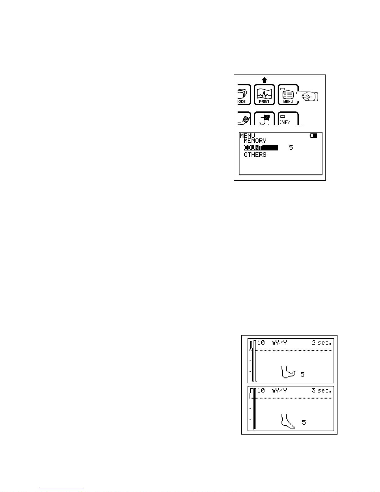
(3) To change the counting number for patient
dorsiflexes, go to the menu and select COUNT and
then press Enter (or Right) until the number
becomes the one desired.
Press MENU button to get out of the MENU mode.
(4) Check that the face of the PPG sensor is free of
stains. Clean it if necessary.
(5) Make certain that room temperature is comfortable
and that the skin surface of the lower limb is warm.
Cold constricts superficial blood vessels and thus
jeopardizes the accuracy of PPG measurements.
Examination Procedure
(1) Have the patient sit on an examination table so that the feet are off the floor.
(2) Apply the sensor, with the clear side against the
skin surface, to the medial malleolus over the
posterior tibial vein. Fix the sensor in place with
double-sided clear tape.
(3) Press PRINT or probe button to begin the
measurement process.
(4) Ask the patient to flex the foot specified number of
times on COUNT following the foot animation on
LCD. The exercise should be forceful, especially
when lifting the foot upward.
(5) After flexing, instruct the patient to relax the foot
and avoid all movement.
Page 50
43
(6) The test is complete when the waveform on the
LCD returns to the baseline amplitude.
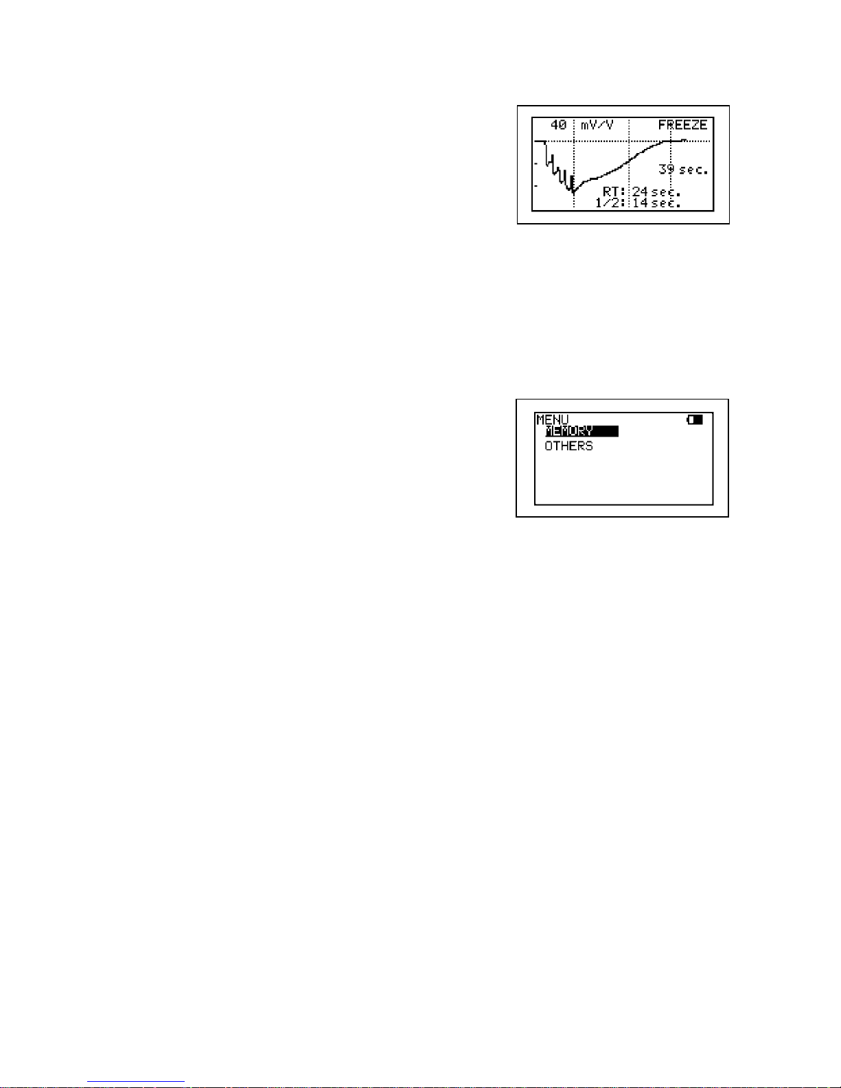
Smartdop will automatically freeze the waveform
and calculate recovery times.
Note: "1/2" is the half recovery time for returning to 50% of
refilling amplitude where middle vertical dotted line
is shown.
Interpretation
Normal: RT > 20 sec
1/2RT > 7 sec
(7) If you wish to save the data on the memory,
see “§ 4-2-7-a. MEMORY - STORE”.
(8) Press the INF/DUMP or probe button* to get out of
the freeze mode.
Note: *When PRB-KEY is on Freeze mode.
Page 51

44
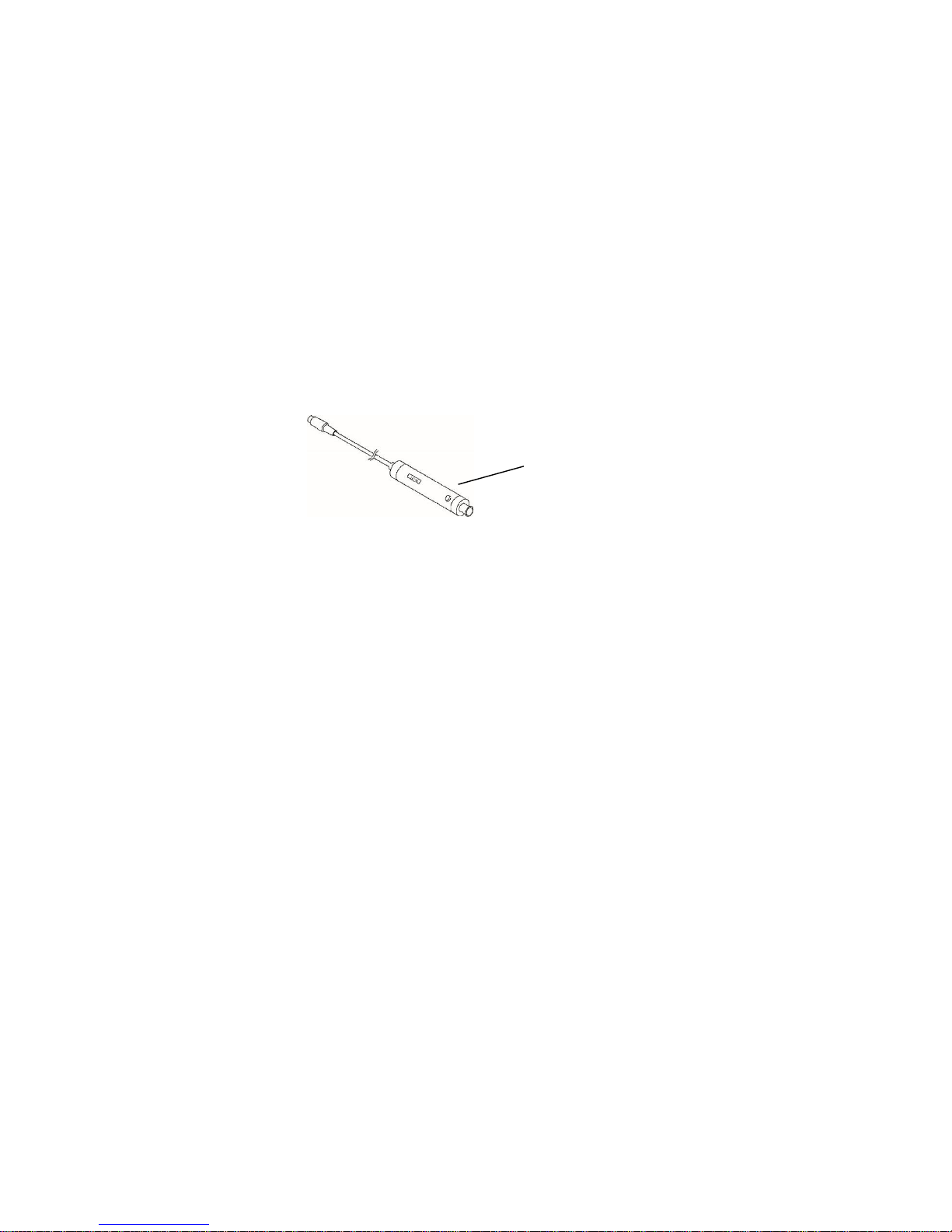
7-3-4. Menu for PPG
Menu
Sub Menu
Selections
Reference in §4-2-7
MEMORY
STORE*3
1 to 30, FREEZE
a. Memory - Store
READ
1 to 30, FREEZE
b, Memory - Read
CLEAR
1 to 30, ALLE
c, Memory - Clear
WAVEFORM *1
PAGE 1, PAGE 2
f. Waveform
COUNT *2
1 to 20 (5)
6-1-6. Count
OTHER
LANGUAGE
ENGLISH, DEUTSCH,
ITALIANO, ESPANOL,
FRANCAIS
k. Others - Language
PRB-KEY
(Probe button)
FREEZE, PRINT, PRT&FRZ
l. Others - PRB-KEY
BACKLIGHT
ON, OFF, 10 to 60 (10-sec steps)
o. Others - Backlight
AUTO-OFF
ON, OFF
p. Others – AUTO-OFF
DISCHARGE*4
q. Others - Discharge
Note *1: WAVEFORM is available only on PPG-AC and Freeze mode.
*2
: COUNT is used for DC mode when in Measurement mode.
*3
: MEMORY - STORE is available only on Freeze mode.
*4
: DISCHARGE is available when AC adaptor is connected to the main unit.
7-3-5. PPG Mode Settings
MODE (AC / DC) (Only available in Measurement mode);
(1) Press MODE button to select the mode. Mode LED corresponding to the mode will
illuminate.
Mode 1: AC coupling mode for arterial pulse waveform studies
Mode 2: DC coupling mode for venous reflux study
COUNT (Only available in DC - Measurement mode);
(1) Go to COUNT on MENU and number for patient dorsiflexes will be shown.
(2) Press Right (or Enter) to change the number and press MENU to get out of MENU
mode.
WAVEFORM;
(1) Go to WAVEFORM on MENU when on PPG-AC and freeze mode and press Right to
show 1st/2nd half of waveform on LCD.
Note: Switching 1st/2nd half can be also done by pressing MODE. See “§ 4-2-7-f. WAVEFORM”.
Page 52
45
7-4. Pneumoplethysmograph
With the PV-21, Smartdop senses volume changes in a limb or digit by measuring the
pressure changes in a recording cuff.
“How to use pneumoplethysmograph” is described in this section.
Built-in cuff inflator works when INFLATOR in menu mode is ON to inflate cuff.
See “§ 7-4-4. PV Mode Setting - INFLATOR” for details.
7-4-1. PV (Pneumoplethysmography) Probe Assemblies
Model PV-21
DC Coupling: Measurement of maximum venous outflow
7-4-2. PV - Measurement of Maximum Venous Outflow
Purpose
Because deep venous occlusion cannot be diagnosed reliably on the basis of presenting
signs and symptoms, pain and swelling being frequently due to other causes, objective
screening tests are of value in confirming or ruling out suspected venous obstructions in
the lower extremities. The test consists of first inducing temporary venous pooling by
means of a constricting thigh cuff followed by measurement of the rapidity of emptying
when the constricting cuff is suddenly vented. Measurement of maximum venous outflow
is frequently employed as an adjunct to Doppler venous compression studies.
Preparation
(1) Connect the PV probe assembly (PV-21) the probe connector #1 or #2 of the main unit,
and turn it on.
(2) Make sure Mode 2 LED (DC mode) illuminates. If not, press MODE button to select
Mode 2 for DC mode.
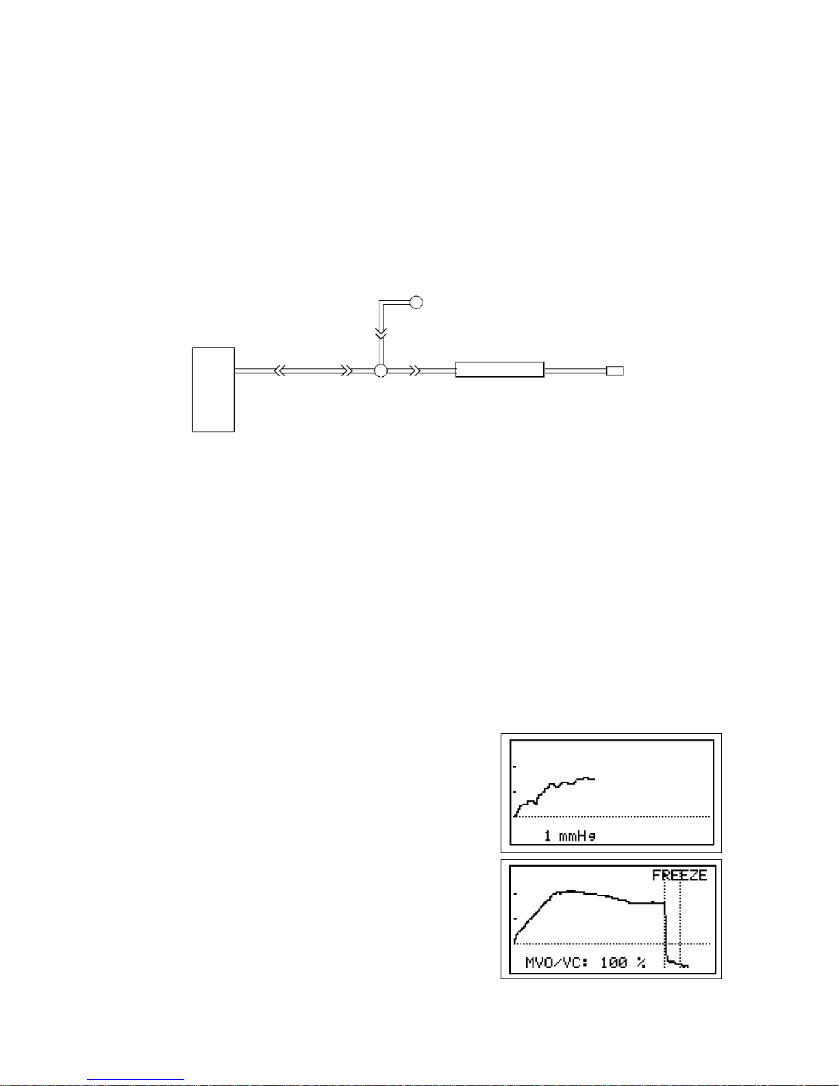
To the main unit
To the cuff
Probe button
Page 53
46
Examination Procedure
(1) Place the patient in supine position with the leg and hip rotated outward. Use pillows to
support the leg and hip. It is important that the patient is comfortable and relaxed.
(2) Wrap a wide occluding cuff at mid-thigh and a sensing cuff at mid-calf.
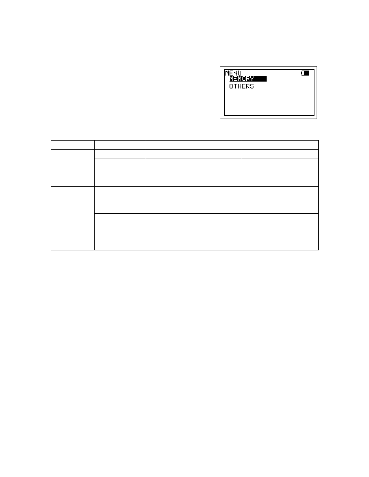
(3) Connect a 3-way stopcock to the inlet of PV probe. Interconnect the stopcock, tubing,
cuff and sphygmomanometer as shown below.
(4) Turn the stopcock so that air is routed from the sphygmomanometer to the sensing cuff
at mid-calf.
(5) Inflate the sensing cuff to 40 mmHg. Wait 10 seconds to allow time for settling and
deflate the cuff to 15 mmHg.
(6) Turn the stopcock so that it blocks sphyg and routes cuff pressure to the PV probe.
(7) Disconnect the sphyg from the stopcock and attach it to the occluding cuff at the thigh.
If INFLATOR is ON, connect occluding cuff to inflation inlet of Smartdop instead of
sphyg with a tubing.
(8) Press PRINT button to begin the measurement process.
(9) Inflate the occluding cuff at the thigh to at least 60
mmHg. If INFLATOR is ON, press INF instead to
inflate cuff. Pressures in sensing cuff are plotted on
the screen. The graph will indicate a gradual
increase in waveform amplitude signifying that
venous outflow is blocked by the occluding cuff.
(10) After 90 seconds, disconnect the sphyg from the
occluding cuff. The pressures on the screen will
drop back to the baseline.
Sphyg
Cuf
Extender
3-way stopcock
To Main unit
PV probe
Page 54
47
(11) Smartdop will automatically stop the measurement process, and then freeze the
waveform. Press PRINT button to print the waveform, if necessary.
(12) If you wish to save the data on the memory, see
“§ 4-2-7-a. MEMORY - STORE”.
(13) Press the INF/DUMP button to get out of the
freeze mode.
7-4-3. Menu for PV
Menu
Sub Menu
Selections
Reference in § 4-2-7
MEMORY
STORE*²
1 to 30, FREEZE
a. Memory - Store
READ
1 to 30, FREEZE
b. Memory - Read
CLEAR
1 to 30, ALL
c. Memory - Clear
IINFLATOR*¹
ON, OFF
6-3-5. Inflator
OTHERS
LANGUAGE
ENGLISH, DEUTSCH,
ITALIANO, ESPANOL,
FRANCAIS
k. Others - Language
PRB – KEY
(Probe button)
FREEZE, PRINT, PRT & FRZ
l. Others - PRB-KEY
AUTO-OFF
ON, OFF
p. Others - AUTO-OFF
DISCHARGE*³
q. Others - Discharge
Note *1: INFLATOR is available only on Measurement mode.
*2
: MEMORY - STORE is available only on Freeze mode.
*3
: DISCHARGE is available when AC adaptor is connected to the main unit.
7-4-4. PV Mode Setting
MODE (AC / DC) (Only Measurement mode);
(1) Press MODE button to select the mode. Mode LED corresponding to the mode will
illuminate.
Mode 1: AC coupling mode for arterial pulse waveform studies
Mode 2: DC coupling mode for measurement of maximum venous outflow
INFLATOR;
(1) Go to INFLATOR on MENU and press Enter or Right to change the mode as follows:
ON: Inflator ON when used with PV-21 without sphyg.
OFF: Inflator OFF when used with PV-21 with sphyg.
(2) When INFLATOR is ON, connect 3-way stop cock to inflation inlet of Smartdop instead
of sphyg with a tubing and Smartdop will inflate the cuff to 60 mmHg automatically.
Page 55

48
8. Technical Information
8-1. Principles
Model Smartdop 30EX is designed to obtain various blood flow velocity through the
ultrasound which is transmitted from probe to patient body and is reflected by the blood
(hemocyte, etc.).
The unit amplifies the high frequency oscillation output and then supplies it to the
transmitter transducer. It is converted to ultrasound by the transducer and the ultrasound is
transmitted to external objects. The ultrasound moves straight through biophysical object,
and is reflected by the moving object (blood flow, fetal heartbeat etc.).
The reflected ultrasound is received by the receiving transducer and is converted into
electric signals again.
The converted signals are amplified and then detected. After removing unnecessary noise
from the signals and improving S / N ratio at the filter circuit, the Doppler shift signals are
amplified and are converted to audible sounds through a speaker or a headset.
Simultaneously, the Doppler shift signals are applied to the CPU and converted to blood
flow velocity waveform signals which can be displayed and printed.
On the ARM / LEG and TOE pressure modes, the blood pressure cuff is wrapped where
the blood pressure is taken and the probe is put on the lower extremity artery by the
operator.
Before the inflation, the peak amplitudes of the blood flow signals should be stable. As the
cuff pressure goes up by activating the inflation pump, the blood vessel is being pressed
and the peak amplitudes become lower. The CPU finds the point where the peak
amplitudes are below the threshold and waits until the cuff pressure is inflated an
estimated 30 mmHg above the point. Then the CPU deactivates the inflation pump and
lets the cuff pressure go down at a moderate rate until the first blood flow signal that
exceeds the threshold is detected.
The cuff pressure at the first signal is the systolic pressure. After confirming a return of the
rhythmical blood flow signals, the CPU opens the air valve to dump the cuff pressure and
displays the systolic blood pressure on the LCD.
Page 56
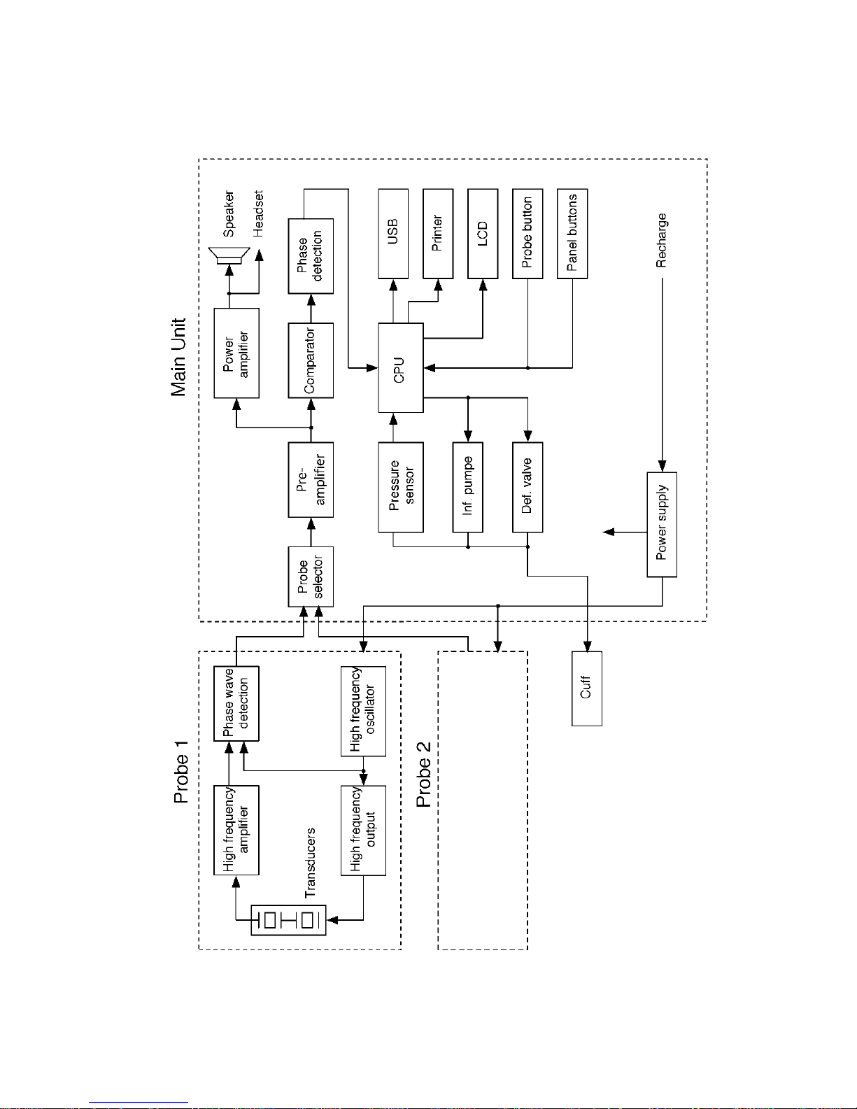
49
8-2. Block diagram
Page 57

50
8-3. Specifications
Probes: Model Freq. Ispta* (in situ) [mW/cm²]
BT2M20S8C 2 MHz 80 mW/cm² or less
BT4M05S8C 4 MHz 390 mW/cm² or less
BT5M05S8C 5 MHz 390 mW/cm² or less
BT8M05S8C 8 MHz 390 mW/cm² or less
BT10M5S8C 10 MHz 390 mW/cm² or less
*Ispta: Spatial Peak - Temporal Average Intensity
Power: Ni-MH rechargeable battery pack or AC adaptor
Input: AC 100-240V- 0.3A (max), 50/60 Hz
Output: DC 12V, 500mA or more
AC Adaptor: Model name: GMPU18UI-3
Consumption: DC 12 V, 500 mA
Recharge: Approx. 4 hours by the AC adaptor
Full charge life: 7 hours or more with printing
Battery life: Approx. 2 years, 300 full charges
Automatic shut-off: No signal: 5 min. Freeze: 10 min. Others: 15 min.
Frequency range: 200 Hz to 5 kHz
Mode settings: Operation, Display, Direction, Memory, Others
Waveform memory: 30 waveforms
LCD display: 128 x 64 dots, STN LCD
Bi-directional blood velocity waveform
Numerical data (Systolic & mean velocities, HR)
Heart rate: 30 to 240 BPM
Blood pressure data (pressure profile, ABI, TBI)
PV-Arterial waveform
Battery level and low battery indicators
Printer: Paper: 58 mm (W) x 25 m/roll (L), Thermal
Resolution: 332 dots/line
Print speed: Approx. 2.5 mm/sec
Accuracy: Velocity:+/-10% or less comparing with internal phantom testing.
Heart rate: +/-5%
Pressure: +/-5 mmHg
Speaker output: 250 mW or more
Inflation rate: 10 - 20 mmHg/sec
Page 58

51
Deflation rate: 2 - 5 mmHg/sec
External outputs: Headset, USB port
Electrical safety: Conform to IEC60601-1
Internally powered equipment
Type BF applied part.
Operating environment: 10 to 37 degrees Centigrade
85% humidity or less with no condensation
Storage and transport environment:
0 to 50 degrees Centigrade
85% humidity or less with no condensation
Dimensions: Main unit: 252 (W) x 192 (D) x 91 (H) mm
(Probe holders not included)
Probe: 20 (Diam.) x 105 (L) mm
Weight: Approx. 1.6 kg (including 1 probe)
Manufacturing date: The first 2 digits and following 2 digits of the serial number
represent the year and month of manufacturing, respectively.
Examples:
03020001: Feb/2003
0401: Jan/2004
* Specifications subject to change
Page 59

52
8-4. Safety standards
The unit confirms to the following standards:
Manufacturing standard: IEC60601-1
(1) Protection class against electric shock : Class II device
: Internally powered equipment
Protection grade against electric shock : Type BF applied part
(2) Electromagnetic emission and electromagnetic immunity
Guidance and manufacturer’s declaration – electromagnetic emissions
The Smartdop 30EX is intended for use in the electromagnetic environment specified below. The
customer or the user of the Smartdop 30EX should assume that it is used in such an environment.
Emissions test
compliance
Electromagnetic environment - guidance
RF emissions
CISPR 11
Group 1
The Smartdop 30EX use RF energy only for its internal
function. Therefore, its RF emissions are very low and are
not likely to cause any interference in nearby electronic
equipment.
RF emissions
CISPR 11
Class A
The Smartdop 30EX is suitable for use in all
establishments other than domestic, and may be used
connected to the public low-voltage power supply network
that supplies buildings used for domestic purposes
provided the following warning in needed:
Warning: This equipment/system is intended for use by
healthcare professions only. This equipment/system may
cause radio interference or may be necessary to take
mitigation measures, such as re-orienting or relocating the
Smartdop 30EX or shielding the location.
Harmonic
emissions
IEC61000-3-2
Class A
Voltage
fluctuations/ flicker
emissions
IEC61000-3-3
Complies
Guidance and manufacturer’s declaration – electromagnetic immunity
The Smartdop 30EX is intended for use in the electromagnetic environment specified below. The
customer or the user of the Smartdop 30EX should assure that it is used in such an environment.
Immunity test
IEC60601 test level
Compliance level
Electromagnetic environment guidance
Electrostatic
discharge(ESD)
IEC61000-4-2
±6 kV contact
±8 kV air
±6 kV contact
±8 kV air
Floors should be wood, concrete
or ceramic tile. If floors are
converted with synthetic
material, the relative humidity
should be at least 30 %.
Electrical fast
transient/burst
IEC61000-4-4
±2 kV for power supply
lines
±1 kV for input/output
lines
±2 kV for power
supply lines
±1 kV for input/output
lines
Mains power should be that of a
typical commercial or hospital
environment.
Page 60

53
Surge
IEC61000-4-5
±1 kV differential mode
±2 kV common mode
±1 kV differential
mode
±2 kV common mode
Mains power should be that of a
typical commercial or hospital
environment.
Voltage dips, short
interruptions and
voltage variations
on power supply
input lines
IEC61000-4-11
< 5% UT
(> 95% dip in UT)
for 0,5 cycles
40% UT
(60% dip in UT)
for 5 cycles
70% UT
(30% dip in UT)
for 25 cycles
< 5% UT
(> 95% dip in UT)
for 5 s
< 5% UT
(> 95% dip in UT)
for 0,5 cycles
40% UT
(60% dip in UT)
for 5 cycles
70% UT
(30% dip in UT)
for 25 cycles
< 5% UT
(> 95% dip in UT)
for 5 s
Mains power should be that of a
typical commercial or hospital
environment.
Power frequency
(50/60Hz)
magnetic field
IEC61000-4-8
3 A/m
3 A/m
Power frequency magnetic fields
should be at levels characteristic
of a typical location in a typical
commercial or hospital
environment.
NOTE UT is the a.c. mains voltage prior to application of the test revel.
Guidance and manufacturer’s declaration – electromagnetic immunity
The Smartdop 30EX is intended for use in the electromagnetic environment specified below. The
customer or the user of the Smartdop 30EX should assure that it is used in such an environment.
Immunity test
IEC60601 test level
Compliance
level
Electromagnetic environment - guidance
Conducted RF
IEC61000-4-6
Radiated RF
IEC61000-4-3
3 Vrms
150 kHz to 80 MHz
3V/m
80 MHz to 2,5 GHz
3V
3V/m
Portable and mobile RF communications
equipment should be used no closer to any
part of the Smartdop 30EX, including cables,
than the recommended separation distance
calculated from the equation applicable to the
frequency of the transmitter.
Recommended separation distance
d = 1.2√P
d = 1,2√P 80 - 800 MHz
d = 2,3√P 800 MHz - 2,5 GHz
where P is the maximum output power rating of
the transmitter in watts (W) according to the
transmitter manufacturer and d is the
recommended separation distance in meters
(m).
Field strength from fixed RF transmitters, as
Page 61
54
determined by an electromagnetic site survey,
a should be less than the compliance level in
each frequency range. b
Interference may occur in the vicinity of the
equipment marked with the following symbol:
NOTE 1 At 80 MHz and 800 MHz, the separation distance for the higher frequency range applies.
NOTE 2 These guidelines may not apply in all situations. Electromagnetic propagation is affected by
absorption and reflection from structures, objects and people.
a Field strengths from fixed transmitters, such as base stations for radio (cellular/cordless) telephones
and land mobile radios, amateur radio, AM and FM radio broadcast and TV broadcast cannot be
predicted theoretically with accuracy. To assess the electromagnetic environment due to fixed RF
transmitters, an electromagnetic site survey should be considered. If the measured field strength in
the location in which the Smartdop 30EX is used exceeds the applicable RF compliance level above,
the Smartdop 30EX should be observed to verify normal operation. If abnormal performance is
observed, additional measures may be necessary, such as reorienting or relocating the Smartdop
30EX.
b Over the frequency range 150 kHz to 80 MHz, field strengths should be less than 3 V/m.
Page 62

Page 63

Page 64

Manufactured by
Hadeco, Inc.
2-7-11 Arima, Miyamae-ku, Kawasaki,
Kanagawa, 216-0003 Japan
September, 2017
Printed in Japan
080-00114-2.6
 Loading...