

Page 1
Kontakt Contact
Hacker Motor GmbH, Schinderstrassl 32, D-84030 Ergolding
Hacker Motor im Internet Hacker Motor on the Internet
Webseite Website: www.hacker-motor.com
Webshop Webshop: www.hacker-motor-shop.com
Anleitungen Manuals: wiki.hacker-motor.com
YouTube-Kanal YouTube channel: www.youtube.com/HackerMotorGmbH
Facebook-Seite Facebook page: www.facebook.com/HackerMotor
CE-Konformitätserklärung
Hiermit erklärt die Hacker Motor GmbH, dass sich dieses Produkt in Übereinstimmung mit den grundlegenden Anforderungen und den übrigen einschlägigen Bestimmungen der EMV-Richtlinie 2014/30/EU bendet.
Die Konformitätserklärung zu diesem Produkt können sie hier anfordern
Hacker Motor GmbH, Schinderstrassl 32, D-84030 Ergolding
oder unter www.hacker-motor.com im Downloadbereich einsehen.
CE Declaration of Conformity (DOC)
Hacker Motor GmbH declares that the product complies with the essential
requirements of the EMC Directive 2014/30/EU.
You can ask for the DOC directly at
Hacker Motor GmbH, Schinderstrassl 32, D-84030 Ergolding
or download at www.hacker-motor.com
Version 1.0 Oktober Version 1.0 October 2018
Artikel-Nr. Kurzanleitung item no quick reference guide: 19871046
© 2018 Hacker Motor GmbH
DPSI Micro MPS Magnetschalter
DPSI Micro MPS magnetic switch
Kurzanleitung Quick reference guide
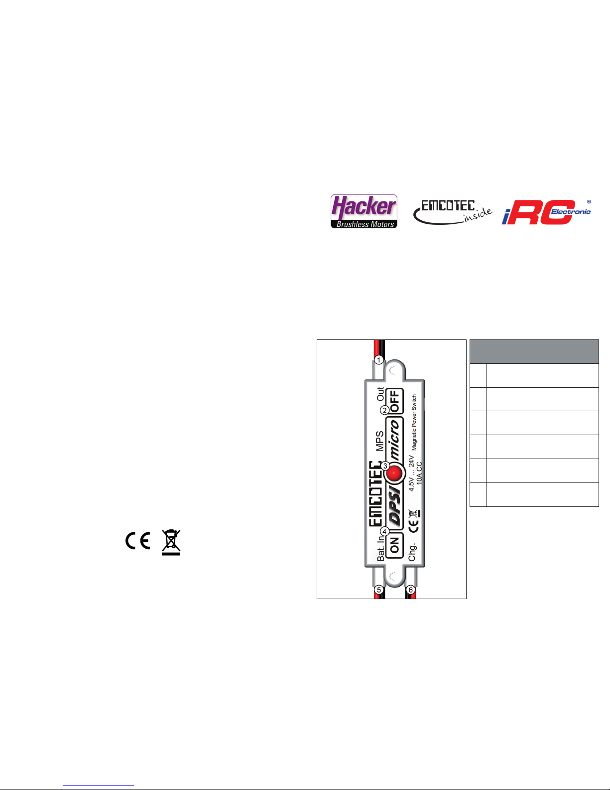
Anschluss, Bedienelemente, Anzeigen
Connections, controls, indications
Tab. 1: Anschlüsse, Anzeigen
Tab. 1: Connections, indications
1
Empfängeranschluss
Receiver connection
2
Ausschaltposition (OFF)
Switching o position (OFF)
3
Rote Status LED
Red status LED
4
Einschaltposition (ON)
Switching on position (ON)
5
Anschluss Akku (Bat.In)
Connection battery (Bat. In)
6
Ladebuchse (Chg.)
Charging socket (Chg.)
Abb. 1 Fig. 1
Made in Germany
Page 2
Tab. 2: Technische Daten Tab. 2: Specications
Betriebsspannungsbereich
Operating voltage range
4,5V ... 24V
4.5V ... 24V
Ausgangsspannung
Output voltage
gleich Eingangsspannung (ungeregelt)
equal to input voltage (unregulated)
Max. Dauerstrom
Max. permanent current
10A
Max. Spitzenstrom
Max. peak current
20A
Max. Ladestrom über Ladebuchse
Max. charging current via
charging socket
3A
Ausführliche Anleitung
Die ausführliche Anleitung und Technische Daten des Produkts nden Sie auf
http://wiki.hacker-motor.com
Detailed manual
Find detailed product manual and specications on
http://wiki-en.hacker-motor.com
Achtung! Attention!
• Der Ausschaltvorgang des DPSI funktioniert mit einem Hallsensor. Hallsensoren reagieren
auf Magnetfelder. Bei sehr starken Magnetfeldern (z. B. Elektroantrieb) kann das DPSI
unter Umständen abschalten. Stromführende Kabel erzeugen ein Magnetfeld. Bitte
verlegen Sie daher alle Kabel, die einen sehr hohen Strom führen (>100A) in einem
Abstand von mindestens 3cm am DPSI vorbei.
• The switching o process of DPSI works with a hall eect sensor. Hall eect sensors can
be inuenced by magnet elds. It is possible that the DPSI switches o when exposed to
a very strong magent eld (i.g. electric drive). Current-carrying cables generate a magnet
eld. So please run all cables which are carrying a high current (>100A) with a distance of
at least 3cm (1.18in) from the DPSI.
!
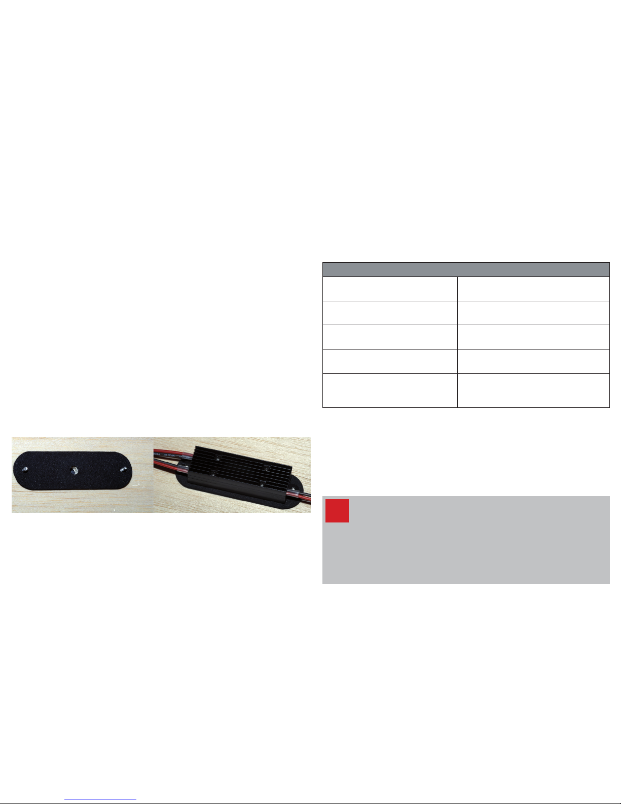
Montagevorschlag
Der DPSI Micro MPS Magnetschalter kann z. B. mit Silikon direkt an die
Rumpnnenseite geklebt oder alternativ von außen an der Rumpfwand festge-
schraubt werden. Die benötigten Löcher können mit Hilfe der im Lieferumfang
enthaltenen Bohrschablone gebohrt werden.
Die beiden Schrauben werden von außen durch die Anschraublöcher ge-
steckt. Die Schrauben fungieren als Positionshilfe für den selbstklebenden
Moosgummistreifen, der als Vibrationsschutz dient. Dieser wird von der Innen-
seite über die beiden Schrauben geschoben und mit der Rumpfwand verklebt.
Um die rote Status-LED (Abb. 1/3) des DPSI Micros von außen zu sehen,
kann ein Loch mit 5mm Durchmesser in die Rumpfwand gebohrt werden.
Mounting suggestion
The DPSI Micro MPS magenetic switch can be sticked on with silicone or
alternatively screwed directly on the fuselage‘s inner sidewall. The required
holes can be drilled using the included drilling template.
Both screws can be feed through the drilling holes from the outside. The
screws are a positioning aid for the self-adhesive foam rubber, which can be
used as vibration protection. It is pushed over the screws from inside and
sticked to the fuselage‘s sidewall.
To see the DPSI Micro‘s red status LED (Fig.1/3) from the outside a hole with
5mm (0.2in) diameter can be drilled in the fuselage wall.
Ein- und Ausschalten
Zum Einschalten des DPSI Micro MPS Magentschalters muss der mitgeliefer-
te Magnet für ca. 1 Sekunde über die Einschaltposition (ON) (Abb. 1/4) gehal-
ten werden. Zum Ausschalten des DPSI Micro DualBat muss der Magnet für
ca. 2 Sekunden über die Ausschaltposition (OFF) (Abb. 1/2) gehalten werden.
Der Ein- und Ausschaltvorgang funktioniert durch die Rumpfwand.
Switching on and o
For switching on the DPSI Micro MPS magnetic switch the included magnet
must be placed over the switching on position (ON) (Fig. 1/4) for approx.
1 second. For switching o the DPSI Micro DualBat the magnet must be
placed over the switching o position (OFF) (Fig. 1/2) for approx. 2 seconds.
The switching on and o process works through the fuselage wall.
Abb. 2 Fig. 2
 Loading...