

Page 1

Hacker Motor GmbH
Bedienungsanleitung für TENSORIC 10 Fahrtenregler
Herzlich Willkommen im Team!
Der TENSORIC 10 Brushless-Fahrtenregler ver wendet die aktuellste Technologie. Unsere
R&D Abteilung hat zusammen mit dem Testteam unzählige Stunden damit verbracht, diesen
Regler zu optimieren. Ein einfaches Handling, sowie optimales Regelverhalt en zeichnen den
TENSORIC 8 aus.
EIGENSCHAFTEN
VORSICHTSMASSNAHMEN & WARNUNGEN
Lesen Sie diese Anleitung vor dem Einsatz ihres neuen TENSORIC 10 sorgfältig durch!
Vermeiden Sie eine falsche Übersetzung indem Sie immer wieder die Motor- und ReglerTemperatur überprüfen.
Achten Sie darauf, dass die Motortem peratur 80°C und die Regler-Temperatur 90° nicht
übersteigt.
MONTAGE
Bei der Montage ist darauf zu achten, dass sie den Regler so positionieren, dass dieser
möglichst geschützt positioniert wird.
Achten Sie darauf, dass Sie nach dem Einbau möglichst einfach an den Schalter , sowie SetKnopf des Reglers kommen.
Nach dem Einbau dürfen keinerlei Kabel an freistehenden Wellen, oder Zahnrädern schleifen.
Versuchen Sie stromführende Komponent en vom Empfänger so weit wie möglich entfernt
einzubauen.
Der TENSORIC 10 ist mit 5 schwarzen AWG 12 Kabeln bestückt, achten Sie auf die Beschriftung ihrer Reglers welche Kabel zum Akku und welche zum Motor gehen! Die K abel A – B – C
sind Motorkabel, die Kabel – und + gehen zum Akku.
ANSCHLUSS VON REGLER UND MOTOR
Stecken Sie ihren TENSORIC 10 aufden Gaskanal (meist Kanal 2) am Empfänger
Verbinden Sie den Regler mit ihrem Motor wie folgt:
Sensorless Brushless Motoren
Sollten Sie den TENSORIC 8 ohne Sensor verwenden, so ist di e Reihenfolge der Verkabelung
prinzipiell egal. Um für einen Sensorbetri eb gerüstet zu sein, empfehlen wir trotzdem, die
Reihenfolge der A-B-C Kabel einzuhalten.
Sollte ihr Motor die falsche Drehrichtung aufweisen, so vertauschen Sie einfac h zwei beliebige
Motorkabel.
Sensor Brushless Motor
Der TENSORIC 8 mit seiner „softsensored“-Technologi e, erkennt automatisch den Anschl uss
eines Sensors-Motors!
Halten Sie die Reihenfolge der A-B-C Kabel unbedingt ein, die Drehrichtung ihres Motors
können sie mit Hilfe der Software oder der optional erhältlichen PROGBOX umstellen.
WARNUNG!
Wenn Sie einen Motor mit Sensor verwenden, müssen Sie auf die korrekte Reihenfolge der AB-C Kabel achten.
Verbinden Sie den Regler mit ihrem Motor wie folgt:
geringer Innenwiderstand
•
spritzwassergeschützt
•
softsensored – der Regler arbeitet bei Unterbrechung des Sensorsignals wei-
•
ter
einfache Programmierung über Set-Taste oder Programmierbox
•
upgradefähig über optional erhältliche Programmierbox
•
getaktetes BEC
•
programmierbares Timing
•
programmierbare Anlaufstufen
•
Regler: Kabel A Motor: Anschluss A
•
Regler: Kabel B Motor: Anschluss B
•
Regler: Kabel C Motor: Anschluss C
•
Regler: Kabel A Motor: Anschluss A
•
Regler: Kabel B Motor: Anschluss B
•
Regler: Kabel C Motor: Anschluss C
•
Schinderstraßl 32
D-84030 Ergolding
Tel.: 0049 (0) 871-953628-0
Fax.:0049 (0) 871-953628-29
ANSCHLUSS VON REGLER UND AKKU
Verbinden Sie ihren Akku über ein passendes Stec ksystem mit dem Regler. Prüfen Sie vor
dem ersten Anschluss ihre Verkabelung!
WARNUNG!
Ein verpolter Anschluss ihres Akkus zerstört ihren Regler!
REGLERKALIBRIERUNG
Damit ihr TENSORIC 10 korrekt funktioniert müssen Sie diesen auf ihre Fernsteuerung
abstimmen.
Um mit der Reglerkalibrierung zu begi nnen, setzen Sie al le Param eter an ihrer Fernsteuerung
zurück.
Befolgen Sie diese Schritte, um den Regler zu kalibrieren
1. Schalten Sie den Regler aus und die Fernsteuerung ein.
2. Stellen Sie die Gas-Trimmung auf neutral und den A us schlag auf 100%. Deak-
FUNKTION DER STATU S LED
In Neutralposition leuchtet kei ne LE D
Die LED am Regler leuchtet rot, wenn das Fahrzeug bremst, oder vorwärts/rückwärts fährt. Bei
Vollgas leuchtet die LED grün.
WARNTÖNE
ERWEITERTE EINSTELLUNGEN
Sie können mit der Setup-Taste, oder mit der zusätzlichen Hacker PROGBOX diverse
erweiterte Einstellungen vornehmen. Um eine Einstel lung mit der Setup -Taste zu verändern,
befolgen Sie die Zusatzanleitung.
1. Schalten Sie den Regler ein
2. Betätigen und halten Sie die Setup-Taste für eine Sekunde, bis die grüne LED zu blinken
beginnt. Danach lassen Sie die Taste l os (beim Halten der “SET”-Taste für 5 S ekunden wird
der Regler auf die Standardeinstell ungen z ur üc k gesetz t)
3. Betätigen Sie die Setup-Taste noch einmal.
4. Die grüne LED blinkt wiederholt 1 mal. Dies zeigt an, dass die Einstellung 1 gewählt ist.
5. Bet ätig en Sie di e Set -Taste 1 mal kurz, gelangen Sie zu Einstellung 2 usw. bis Sie durch
alle Einstellungen geblättert haben, danach kommt erneut Einstellung 1.
6. Um eine Einstellung zu ändern, drücken und halten S ie (bei der gewünschten Einstell ung)
die Setup-Taste für 3 Sekunden.
7. Die rote LED wird nun den Wert der Einstellung anzeigen:
blinkt sie 1 mal, so beträgt der Wert 1, blinkt sie 2 mal, beträgt der Wert 2 usw.
8. Drücken Sie die Set-Taste, um den Wert zu verändern.
9. Wenn Sie den gewünschten Wert eingestell t haben, drücken und halten Si e die Set -Taste
für 3 Sekunden, um die Änderung zu speichern.
10. Schalten Sie den Regler aus und wieder ein, um die neue Einstell ung z u ak tivieren.
Bitte beachten:
Sie können jeweils nur eine Einstell ung verändern. Nach jeder Veränderung muss der Regler
ein- und ausgeschaltet werden.
tivieren Sie Spezialfunktionen wie AB S etc.
3. Drücken und halten Sie die “SET”-Taste (auf dem Ein-/Aus-Schalter) und
schalten Sie den Regler ein.
4. Lassen Sie die “SET”-Taste los, sobald am Regler die LED rot blinkt.
5. Stellen Sie die folgenden Positionen am Sender ein und bestätigen S ie jeweil s
mit der “SET”-Taste:
o Neutralpunkt (LED blinkt 1 mal)
o Vollgas (LED blinkt 2 mal)
o Vollbremse/rückwärts (LED blinkt 3 mal)
6. Der Motor piept nach dem letzten Schritt für 3 Sekunden. Danach ist der Vorgang abgeschlossen.
7. Schalten Sie ihren Regler aus.
1. Problem mit Eingangsspannung:
Der Regler prüft die Eingangsspannung, sobald er eingeschalt et ist. Wenn ein
Problem erkannt wird, ertönen wiederholt zwei Signaltöne im Abstand von einer Sekunde (xx-xx-xx).
2. Problem mit dem Empfangssignal:
Der Regler prüft das Empfangssignal, sobald er eingeschaltet ist. Falls ein
Problem besteht, ertönt wiederholt ei n Signalton im Abstand v on zwei Sekunden (x-x-x).
EINSTELLUNGSMÖGLICHKEITEN
Betriebsmodus
1. “Vorwärts/Bremse” ist für den Wettbewerbseinsatz geeignet. In diesem Modus können Sie
nur vorwärts fahren und bremsen. Die Rückwärtsf ahr t ist nicht möglich.
2. “Vorwärts/Rückwärts mit Bremse” ist der Modus für den Allround-Einsatz. Ihr Fahrzeug kann
damit vorwärts und rückwärts fahren. Wenn Sie den Gashebel während der Vorwärtsfahrt auf
Rückwärtsposition stellen, bremst das Fahr z eug bis zum Stillstand. Es ist nicht möglich, den
Motor rückwärts drehen zu lassen, bevor das Fahrzeug zum Stillstand gekommen ist. Wenn
Sie rückwärts fahren wollen, müssen Sie den Gashebel nach der V ollbremsung wieder auf die
Neutralposition bewegen, bevor Si e ihn zur Rück wärtsfahr t wieder auf Rückwärtsposition
bringen.
Wenn Sie bremsen oder rückwärts fahren und danac h in eine Vorwärtsposition übergehen,
fährt das Fahrzeug umgehend vorwärts.
3. “Vorwärts/Rückwärts” ist f ür Rock Crawler geeignet. Dieser Modus hat kei ne Bremse. Das
Fahrzeug kann zudem direkt von Vorwärts- zu Rückwärtsfahrt wechseln. Verwenden Sie
diesen Modus nicht mit anderen Autos, da der Fahrtenregl er sonst be schädigt werden kann.
Automatik-Bremse
Bremst das Fahrzeug automatisch ab, wenn der Gashebel in die Neutralpositi on geführt wird.
Dies simuliert die Motorbremse eines echten Fahr z eugs.
Akku-Abschaltspannung
Diese Funktion dient dazu, eine Tiefentl adung des Akk us zu verhindern.
Achtung moderne Akku benötigen eine höhere Abschaltspannung, da sie aufgrund ihrer
Entladekurve sehr schnell Tiefentladen werden!
Das eingestellte Limit ist abhängig von der i ndiv iduellen Zellspannung.
Startmodus
Diese Einstellung ermöglicht es, die Beschleunigungscharakteristik des Fahrzeugs zu
verändern. Level 1 ergibt eine sehr feine Beschleunigung und Level 9 beschleunigt sehr stark
aus dem Stand. Diese Funktion ist v on der Wirkung her wie die Exponentialfunktion an der
Fernsteuerung. Bei den Levels 7, 8 und 9 sind Hochleistungsakkus zwingend Notwendig, um
eine Überlastung des Akkus, schlechte Leistung oder unv orhergesehene Komplikationen zu
vermeiden.
Maximale Bremskraft
Diese Einstellung betrifft die maximale Bremskraft des Reglers. Ein höherer Wert f ührt zu
stärkerer Bremskraft.
Maximale Rückwärts-Leistung
Diese Einstellung stellt die maximale Leistung für die Rückwärtsfahrt ein.
Minimalbremskraft
Mit dieser Einstellung können Sie die minimale Bremskraft beim Betätigen der Bremse
verändern.
Der Minimalwert dieser Einstellung ist mit dem Wert der Automatik-Bremse identisch kann aber
auch individuell eingestellt werden.
Neutral-Bereich
Diese Einstellung betrifft die Empfindlichkeit des Regelverhaltens um den Neutral punk t.
Timing
Diese Einstellung verändert das Tim ing des Motors. Mehr Tim ing ergibt mehr Leistung, doch
kann die Effizienz verringert werden und den Motor oder Regler beschädigen.
Motor Drehrichtung
Diese Einstellung erlaubt es, die Drehric htung des Motors zu ändern.
LiPo-Zellenzahl
Der TENSORIC 10 besitzt eine Automatik-Erkennung für die Zellenanzahl ihres Akkus. Mit
dieser Einstellung überschreiben Si e den Wert der automatisch erkannt wurde und geben
manuell die Zellenanzahl ihres Fahrakkus an.
Auf Werkseinstellungen zurücksetzen
Drücken und halten Sie die “SET”-Taste 5 Sekunden lang (Gashebel in Neutralposition): die
rote und grüne LED beginnen gleichzeitig zu blink en, sobald alle Werte auf die Werkseinstellung zurückgesetzt worden sind.
SOFTWARE UPDATE
Die stätige Weiterentwicklung unseres Team führt auch zu Verbesserungen der Reglersoftware. Eine aktualisierte Firmware für ihr en TENS ORIC 10 Fahrtenregler finden Sie auf unserer
Webseite: www.hacker-motor.com, oder auf unserer CARLINE-Webseite
carline.de
Für die Aktualisierung ihres Fahrtenr eglers benötigen Sie die Hacker PROGBOX als Interface.
www.hacker-
Page 2
EINSTELLUNGEN / PROGRAMMIERUNG
Daten Best.-Nr.
71900100
Konstantstrom
160A
Max. Strom
760A
Innenwiderstand
0,00025 Ohm
Funktionen
Forwärts/Bremse
Forwärts/Rückwärts
Akkutyp
1-3S LiPo/LiFe
5-9S NiMh
BEC
5,8V max. 3A
LxBxH
41,5x30x20,4mm ohne Lüfter
Gewicht
44g ohne Kabel
Benutzerinformatione zur Entsorgung von elektrischen Geräten und
Bitte beachten Sie die Zusatzinformationen am Ende dieser Bedienungsanleitung.
WARNUNGEN & HINWEISE
o Dieser Regler ist kein Spielzeug! Lassen Sie Kinder beim Gebrauch dieses
Produkts nie unbeaufsichtigt.
o Lassen Sie den Regler nie unbeaufsichtigt im eingeschalteten Zustand.
o Der Regler darf im Bereich von brennbaren Materialien nicht verwendet wer-
den!
o Sollte der Regler nicht richtig funktionier en, ziehen Sie sofort den Akku ab und
kontaktieren Sie den Fachhandel.
o Der Regler muss immer Stromlos gelagert werden – nach dem Gebrauc h im-
ALLG. GEWÄHRLEISTUNGSBESTIMMUNGEN
Produkte der Hacker Motor GmbH werden nach strengsten Qualitätskriterien
gefertigt.
Wir gewähren die gesetzliche Gewährleistung auf P r oduk tions- und Materialfehler, die zum
Zeitpunkt der Auslieferung des Produkts vorhanden waren.
Für gebrauchstypische Verschleiß er scheinungen wird nicht gehaftet.
Diese Gewährleistung gilt nicht für Mängel, die auf eine unsachgemäße Benutzung, mangelnde Wartung, Fremdeingriff, oder mechanische Beschädigung zurückzuführen sind.
Dies liegt unter Anderem vor bei:
Bevor Sie dieses Produkt zur Reparatur einsenden, prüfen Sie bitte zunächst alle anderen
Komponenten um andere Störquellen und Bedi enfehler auszuschließen.
REPARATURBESTIMMUNGEN
Mit der Einsendung des Produktes muss der Kunde mitteil en, ob das Produkt in jedem Fall
repariert werden soll. Sollte kein Gewährleistungs- oder Garantieanspruch bestehen, erfolgt
die Produktüberprüfung und ggf. Reparatur in jedem Falle kostenpflichtig gemäß unserer
Preisliste. Ein Gewährleistungs- oder Garantieanspruch kann nur anerkannt werden, sofern
eine Kopie des Kaufbelegs beigefügt i st. Auf Anf or der ung erstel len wir gerne ein kostenpflichtiges Reparaturangebot. An unser Reparaturangebot sind wir zwei Wochen ab Ausstellungsdatum gebunden. Bei Beauftragung der Reparatur werden di e K osten für das Reparaturangebot nicht berechnet. Für eine schnelle Abwicklung Ihres Servicefalls legen Sie bitte eine
ausführliche Fehlerbeschreibung und i hr e A dr essdaten der Ei nsendung bei .
mer Akku abstecken!
o Empfängerkabel und/oder Schalter beschädigt
o mechanische Beschädigung, oder Zer stör ung des Gehäuse s
o Wasser oder Wasserrückstände im Gehäuse
o Mechanische Beschädigung der Bauteil e und / oder der Platine
o Auf der Platine gelötet (Ausnahme außen li egende Lötsockeln)
o Akkuseitig verpolt
TECHNISCHE DATEN
Forwärts/Bremse/Rückwärts
FEHLERSUCHE
S = Symptom P = Problem L = Lösung
S: Regler eingeschaltet, jedoch kei ne Funktion des Motors und keine Signaltöne.
P: Problem mit Akkuanschluss, oder Ein-/Ausschalter
L: Überprüfen Sie ihre Verbindung zum Akku, sowie ihren Schalter
S: Regler eingeschaltet, keine Motorfunk tion, zwei Reglersignal mit Pause von einer Sekunde
P: Eingangsspannung zu hoch, oder zu niedrig
L: Überprüfen Sie ihren Akku
S: Regler eingeschaltet, keine Motorfunk tion, rote LED leuchtet
P: Empfangssignal gestört
L: Überprüfen Sie ihre Fernsteuerung und ihren Empfänger, sowie den Anschluss ihres
Reglers am Empfänger.
S: Motor dreht in die falsche Richtung
P: Motor falsch angeschlossen, oder Regler nic ht richtig eingestellt
L: Bei sensorlosem können Sie zwei Kabel am Motor vertauschen, oder wec hs eln Sie die
Motordrehrichtung mittels der Regler-Software.
S: Motor stoppt plötzlich
P: Akkuabschaltung, oder Überhitz ungsschutz ak tiv
L: Beachten Sie die Regler LED! Blinkt diese rot ersetzen, oder laden Sie ihren Akku. Blinkt die
LED an ihrem Regler grün, so lassen Sie ihr System abkühlen und überprüfen Sie ihr System
auf Kühlung, Übersetzung, oder Defekte.
S: Motor unterbricht Funktion, oder stott er t bei der Beschleunigung
P: Akku-Leistung zu gering, oder Untersetzung zu groß
L: Wechseln Sie auf einen Hochleistungsakku, oder tauschen Sie ihren Motor gegen einen
Leistungsärmeren aus. Oftmals genügt eine ander e Untersetzung. Überprüfen Sie auch ihre
Reglereinstellung.
S: Bei Neutralstellung des Gashebels blinken die rote und grüne LED gleichzeitig
S: Motor stoppt plötzlich
P: Akkuabschaltung, oder Überhitz ungsschutz ak tiv
L: Beachten Sie die Regler LED! Blinkt diese rot ersetzen, oder laden Sie ihren Akku. Blinkt die
LED an ihrem Regler grün, so lassen Sie ihr System abkühlen und überprüfen Sie ihr System
auf Kühlung, Übersetzung, oder Defekte.
S: Der Motor stottert und dreht nicht
P: Problem mit Motoranschluss
L: Überprüfen Sie ihren Motoranschluss – Kontaktieren Sie unseren Support.
KONFORMITÄTSERKLÄRUNG
Für di e in dieser Anleitung erwähnten Produkte aus unserem Hause gilt die einschlägige und
zwingende EG Richtlinie:
EMV-Richtlinie: 2004/108/EG
Folgende Fachgrundnormen wurden herangezogen:
EN 61000-6-1:2007
EN 61000-6-3:2007
Ergolding, 04.02.2012
Dieses Symbol auf Produkten und/oder begl eitenden Dokumenten bedeutet, dass elektr ische
und elektronische Produkte am Ende Ihrer Lebensdauer vom Hausmüll getrennt entsorgt
werden müssen.
Bringen Sie bitte diese Produkte für die Behandl ung, Rohstoff rück gewinnung und Recycli ng zu
den eingerichteten kommunalen Sammelstell en bzw. Wertstoffsammel höfen, da diese Geräte
kostenlos entgegennehmen.
Die Ordnungsgemäße Entsorgung dieses Produkts dient dem Umwelt schutz und verhindert
mögliche schädliche Auswirkungen
auf Mensch und Umwelt, die sich aus einer unsachgem äßen Handhabung der Geräte am
Ende ihrer Lebensdauer ergeben könnten.
Genauere Informationen zur nächstgelegenen Sammel stelle bzw. Recyclinghof erhalten Sie
bei Ihrer Gemeindeverwaltung.
Für Geschäftskunden in der Europäischen Union
Bitte treten Sie mit Ihrem Händler oder Lieferanten in Kontakt, wenn Sie elektrische und
elektronische Geräte entsorgen möc hten. E r hält weitere Informationen für Sie bereit.
Informationen zur Entsorgung in Ländern außerhalb der Europäischen Union.
Dieses Symbol ist nur in der Europäischen Union gültig.
Hacker Motor GmbH
Schinderstraßl 32
D-84030 Ergolding
Tel: +49 871-953628-0
Fax: +49 871-953628-29
Email: info@hacker-motor.com
Copyright ©, Hacker Motor GmbH 2012
Irrtum und Änderungen vorbehalten
WEEE-Reg.- Nr. DE55352581
elektronischen Geräten (priv ater Haushal t)
Entsprechend der grundlegenden Firmengrundsätzen wurde ihr
Produkt aus hochwertigen Materiali en her gestellt, die recyclebar und
wieder verwendbar sind.
Copyright© 2012 Hacker Motor GmbH. All rights reserved
.
Page 3

Hacker Motor GmbH
Schinderstraßl 32
D-84030 Ergolding
Tel.: 0049 (0) 871-953628-0
Fax.:0049 (0) 871-953628-29
info@hacker-motor.com
Manual for TENSORIC 10 electronic speed control
Welcome to the team!
The TENSORIC 10 Brushless electronic speed control is driven by the latest technology. Our
R&D department has spent hours and hours together with our drivers-team to optimize this
controller. Easy handling and optimal control behavior is characterized by the TENSORIC 10.
FEATURES:
• lowest internal resistance
• splash water protected
• softsensored
• Easy setup with Setup button or optional programming box
• Forward – break – backward function
• Several programmable parameters
PRECAUTIONS & WARNINGS
Read these instructions carefully before using your new TENSORIC 10!
Avoid using a wrong gear ratio by continuously monitoring the motor and controller temperature.
Make sure that the motor temperature does not exceed 80 ° C and the controller temperature
does not exceed 90 °C.
ASSEMBLY
When mounting, ensure that the position of the controller is in a way that it is protected.
Make sure that you have after the installation an easy as possible access to the switch, as well
as setup button of the controller.
Please ensure that after installation, no cables can drag on free-standing shafts, or gears. Try
to place electrical components eg. receiver away from the controller as far as possible.
The TENSORIC 10 is equipped with 5 black 12 AWG cables, pay attenti on to the l abels of the
controller which cabl es belongs to the battery and which cable belongs to the engine! The
cable A - B – C belongs to the motor, the cables - and + belongs to the battery.
CONECTION OF CONTROLLER AND MOTOR
Connect the TENSORIC 1 0 to your throttle channel (mostly channel 2) on your receiver.
Connect motor and controller as follows:
Sensored brushless motor wiring
When using brushless motor with Hall Sensor,it is necessary to connect t he sensor cable to
the “SENSOR” port on the ESC, and ESC can automatically identify the motor type
(sensored or sensorless) by detecting the si gnal coming from the SENSOR port.
Sensorless brushless motor wiring
When using brushless motor without Hall Sensor, the #A, #B, #C wires of the ESC can be
connected with the motor wires fr eely ( without any sequence). If the motor runs in the opposi te
direction, please swap any two wire connections.
WARNING!
For sensored brushless motor, the #A, #B, #C wires of the ESC MUST be connected with the
motor wire #A, #B, #C respectively. Do not change the wires sequence optionally!
controller: cable A motor: connection A
•
controller: cable B motor: connection B
•
controller: cable C motor: connection C
•
CONNECTION OF CONTROLLER AND BATTERY
Connect your battery via a suitable plug-in system with the controller.
Check the wiring before first use!
Attention!
A reverse polarity connection of your batteries will destroy the controller!
CONTROLLER CALIBRATION
In order to ensure a proper function of your controller you have to adj ust your controll er to your
transceiver.
To start with the calibration please reset all functions on your transceiver.
Please follow the steps below to calibrate your controler
1. Turn off your controller and transceiver.
2. Set your throttle trim on neutral and the range at 100%. Reactiv ate special
CHECK THE LED STATUS IN NORMAL RUNNING
Normally, if the throttle stick is in the neutral range, neither the red LED nor the green LED
lights.
The red LED lights when the car is running forward or backward and it will flash quickly when
the car is braking.
The green LED lights when the throttle stick is moved to the top point of the forward zone.
ALLERT TONES
ADVANCED SETTINGS
By using the setup – button or the Hacker PROGBOX it is possible to have some advanced
setups.
Please follow the steps below: Further information you will find at the end of the manual.
1. Switch on the controller
2. Push and hold the setup-button, until the green LED is flashing. Release the setup – button
as soon as the LED is flashing green
3. Push the setup – button once again.
4. The green LED is flashing a single signal to identicate the setting 1.
5. To rotate through the advanced setup menu push the setup button again shortly
6. To change a setting, press and hold (at the desired setting), the setup button for 3 seconds.
7. The red LED display is now the value of the setting:
LED blinks 1 time, for the value 1, LED blinks 2 times, the value 2, etc.
8. Press the Set button to change the value.
9. If y ou have set the desired val ue, press and hold the Set but ton for 3 seconds to sav e the
change.
10. Switch off the controller in order to activ ate the new setup
Please note:
You can chance only one setting at t he time. After every single change you have to switch off
and switch on the controller
functions like ABS eg.
3. Push and hold the “SET”-button (located at the on/off switch) and t urn on the
controller.
4. Release the “SET”-button as soon as the LED is flashing red.
5. Set the following positions on your t ransceiver and confi rm with t he "SET" button:
o Neutral (LED flashing 1 time)
o Full throttle (LED flashing 2 times)
o Full break/backwards (LED flashing 3 times)
6. The Motor will quit with a beep for 3 seconds after the last step. Then you have
succesfully finished.
7. Turn off your controller.
1. Input voltage abnormal alert tone: The ESC begins to check the input voltage
when powered on, if the voltage is out of the normal range, such an alert tone
will be heard: “beep-beep-, beep-beep-, beep-beep-” (T here is 1 second interval between every group of “beep-beep-” tone).
2. Throttle signal abnormal alert tone: When the ESC can’t detect the normal
throttle signal, such an alert tone will be heard: “beep-, beep-, beep-” ( There is
2 seconds interval between every “beep-” tone).
SETTING OPTIONS
Explanation for each programmable item
1. “Running Mode” with “Forward with Brake” mode, the car can go forward and brake, but
cannot go backward, this mode is suitable for competi tion; “ Forward/Reverse with Brake” mode
provides backward function, which is suitable for daily training.
2. “Forward/Reverse with Brake” mode uses “Double-click” method to make the car go
backward. When you move the throttle stick from forward zone t o bac k ward zone f or the 1st
time (The 1st “click”), the ESC begins to brake the motor, the motor speeds down but it is still
running, not completely stopped, so the backward acti on is NOT active immediately. When the
throttle stick is moved to the backward zone for the 2nd time (The 2nd “ cli c k ” ), if t he m otor
speed is slowed down to zero (i.e. stopped), the backward act ion will happen. The “DoubleClick” method prevents mistaken reversi ng ac tion when the brake function is frequentl y used i n
steering. By the way, in the process of brake or reverse, if the t hr ottl e stick is moved to forward
zone, the motor will run forward at once.
3. “Forward/Reverse” mode uses “Singl e-click” method to make the car go backward. When
you move the throttle sti ck from forward zone to backward zone, the car will go backward
immediately. This mode is usually used for the Rock Crawler.
Drag Brake Force:
Set the amount of drag brake applied at neutral throt tle to simulate the slight braking
effect of a neutral brushed motor while coasti ng.
Low Voltage Cut-Off:
The function prevents the lithium battery pac k fr om over discharging. The ESC detects
the battery’s voltage at any time, if the voltage is lower than t he threshold for 2 seconds, the
output power will be reduced 70%, after 10 seconds the output will be completel y stopped, and
the red LED flashes in such a way:“☆-☆-, ☆-☆-, ☆-☆-”.
There are 6 preset options for this item. You can customize the cutoff threshold by using an
advanced LCD program box (optional equipment) t o trim it with a step of 0.1V, so it will be
more suitable for all ki nds of bat teries (Ni MH, Ni C d , Li -ion, Li po, LFP, etc). Pl ease always keep
in mind that the customized value is not for each cell, it is for the WHOLE battery pack.
Start Mode:
Select from “Level1” to “Level9” as you like, Level1 has a very soft start ef f e c t, whil e l evel9 ha s
a very aggressive start effect. From Level1 to Level9, the start force is increasing. Please note
that if you choose “Level7” to “ Level9” mode, you must use good quality battery pack wit h
powerful discharge ability, otherwise these modes cannot get the burst start effect as you want.
If the motor cannot run smoothly (the motor is trembling), it may caused by the weak discharge
ability of the battery pack, please choose a better battery or increase the gear rat io (Use a
smaller pinion).
Maximum Brake Force:
The ESC provides proportional brake functi on. The brake force is related to the positi on of the
throttle stick. Maximum brak e force refers to the force when t he throttle sti ck is located at the
top point of the backward zone. A very large brake force can shorten the brake time, but it may
damage the gears. The “Disable” opti on inhibits the inherent brake function of the speed
controller. When this option is select ed, the brake function is realized by a traditional disc-brake
system driven by a servo.
Maximum Reverse Force:
Sets how much power will be applied in the reverse direction. Different value makes different
reverse speed.
Initial Brake Force:
It is also called “minimum brake force”, and it refers to the force when the throttle stick
is located at the initial position of the backward zone. The default value is equal to the
drag brake force, so the brake effect can be very smoothly.
Neutral-Range
This setting affects the sensitivity of t he contr ol r esponse around neutral.
Timing
The “timing” item is usable for both sensored and sensorl ess brushless motors. There are
many differences among structures and param eters of different brushless mot ors, so a fixed
timing ESC is difficult to comparate with all brushless motors. It is necessary to make the
timing value programmable. Pl ease select the most suitable timing v alue according to the
motor you are just using. Generally, higher timing value brings out higher power output, but the
whole efficiency of the system will be slightl y reduced.
Motor Rotation:
You can use this item to change the rot ation direction. Face to the motor shaft (That means the
rear cover of the motor is far from your f ace), and move the t hrottl e sti ck to the t op point of the
forward zone. If this item is set to “CCW”, the shaft runs counter-cl ockwise; If this item is set to
“CW”, the shaft runs clockwise.
Page 4
Lipo Cells:
Data Order-Nr.
71900100
Constant current
160A
Max. current
760A
Internal resistance
0,00025 Ohm
Function
Foreward/Brake
Foreward/Backward
Battery typ
1-3S LiPo/LiFe
5-9S NiMh
BEC
5,8V max. 3A
LxBxH
41,5x30x20,4mm without fan
Weight
44g without cable
Hacker Motor GmbH
Information for Users on disposal of electrical equipment and
We strongly suggest setting the “Lipo Cells” item manuall y. Because the normal voltage of
each Lipo cell varies from 2.6V to 4.2V, it is quite difficult to calculate the cells number of a
discharged Lipo battery pack. If it is calculated incorrectly, the Low Voltage Cutoff Protecti on
function m ay work abnormally, so the option “Auto Calc ulate” is only avail able for 2s, 4s and
6s Lipo. If the voltage of the battery pack is lower than 8.8V, it is judged as a 2s Lipo; If the
voltage is between 8.8V to 17.6V, it is judged as a 4s Lipo; If the voltage i s higher than 17.6V,
it is judged as a 6S Lipo. So in order t o make the Low Voltage Cutoff Protection functi on
correctly, please set the “Lipo Cells” it em manually.
Software update:
The continuous development of our team also leads to improv ements in the control software.
An update of the firmware for t he TENSORIC 8 ES C is available on our Website: www.hackermotor.com.
For updating of the controller you need the Hacker PROGBOX as an int erface.
Reset All Items To Default Values:
At any time when the throttle i s located in neutral zone (except in the throttle c alibration
process or ESC program mode), hold the “SET” key for over 3 seconds, the red LED and
green LED will flash at the same time , which means each programm able it em has be reset to
its default value.
SETTING / PROGRAMMING
Please refer to the additional information at the end.
WARNINGS & INFORMATIONS
o This controller is not a toy! Do not leave children unattended when using this
product.
o Do not leave the controller unattended when switched on.
o The controller may not be used in the range of combustible materi als!
o If the controller does not work properly, disconnect the battery immediately
and contact the dealer.
o The controller must always be stored without a battery connect ed - Discon-
GERNERAL WARRANTY PROVISIONS
Hacker Motor GmbH products will be manufactured in accordance with the highest quality
criterias.
We provide the legal guarantee, to be free of defect s on material and workmanship.
There will be no liability for typical use sign of wear.
The warranty does not cover defects which are a result of mi suse, improper maintenance, or
mechanical damage.
This is among other things on:
o connector cut off or placing a non-polarized connector system
o switch wire damaged
o mechanical damage, or destruction of the housing
o water or residual water in the housing
o Mechanical damage to the electronic components and / or the board
o soldered on the PCB (except on external soldering sockets)
o Battery polarity reversed
Before returning your product for repair, pl ease check all other components in or der to avoid
any operator error.
.
REGULATIONS FOR REPAIR
By returning of the product, the customer, should identify whether the pr oduct will be repair ed
in any case or not. In the case that no warranty or guarantee applies, the product testing and
possible repair or service will be charged according to our price list. A guarantee or warranty
can only be accepted if a copy of your rec eipt is attached. On request, we will offer you a
repair quote. On our repair quote, we are bound for two weeks from the date of issue. By
carrying out the repair the cost f or the repair quote will not be charged. For quick repai r and
return service, please provide a detailed description of the failure and full address details.
nect the battery immediately after use!
MAIN APPLICATIONS
Foreward/Brake/Backward
TROUBLE SHOOTING
T = Trouble P = Possible Reason S = Solution
T: After power on, motor doesn’t work, and the cooling fan doesn’t work
P: The connections between battery pack and ESC are not correct
Check the power connections / Replace the connectors
S
T: After power on, motor can’t work, but emits “beep-beep-, beep-beep-” al er t tone. (Every
group of “beep-beep-” has a time interval of 1 second )
P: Input voltage is abnormal, too high or too low
S: Check the voltage of the battery pack
T: After power on, red LED always lights, the motor doesn’t work
P: Throttle signal is abnormal
S: Plug the control wire into the throttle channel of the receiver correctly.
T: The motor runs in the opposite direction when it is accelerated
P: The wire connections between ESC and the motor are not corr ect
S: 1) For sensorless motor: Swap any two wire connect ions between the ESC and the motor.
Or use the method #2 2) For sensored motor: Please check the wire connec tions, they must be
A-A, B-B, C-C respectively. If the connections are correc t, please change the “Motor Rotation”
programmable item to “CW(Clockwise)”
T: The motor suddenly stops running while in working state
P: The throttle signal is lost or the ESC has entered the Low Voltage Pr otection Mode or Over-
heat Protection Mode
Check the transmitter and the receiver Check the signal wir e from the throttle channel of
S:
your receiver or Red LED flashing means Low voltage protection. Green LED flashing means
Over-heat protection
T: When accelerating quickly, the motor stops or trem bles
P: 1) The battery has a bad discharge performance 2) The gear rate is too small 3) The “Start
Mode (Punch)” of the ESC is too aggressive
1) Use a better battery 2) Use lower KV motor or change the gear rate, choose smaller
S:
pinion 3) Select a softer option for the “Start Mode (Punch)”
T: When the throttle stick is in the neutral range, the red LED and the green LE D flashes
synchronously
P: The motor is a sensored motor, but the ESC detects abnormal signal f r om the sensor, so it
changes to sensorless mode automatically
S: 1) Check the connection of Hall sensor cable to make it firmly connect the motor with the
ESC 2) The Hall sensors in the motor are damaged, please change the mot or
DECLARATION OF CONFORMITY
For the products manufactur ed by Hacker Motor GmbH menti oned in this manual the compelling and relevant EC Directive will apply:
EMV-Directive: 2004/108/EG
The following special directiv es will appl y:
EN 61000-6-1:2007
EN 61000-6-3:2007
Ergolding, 04.02.2012
This symbol on the products and / or accompanying documents means that used electrical and
electronic products must be at the end of their lifetime seperated from household waste.
Please take these products for the treatment , rec overy and recycling to designated collection
points, which will receive the devices free of char ge.
The Proper disposal of this product, prevent any potential adverse effects on humans and the
environment which could otherwise ari se from inappropriate waste handl ing at the end of its
lifetime. For more precise details of your nearest designat ed coll ection poi nt, c ontact your l ocal
authority.
For business users in the European Union
Please contact your dealer or supplier for fur ther information if you wish to dispose electrical
and electronic equipment. He holds further information ready for you.
Information on Disposal in other Countries outsi de the European Union.
This symbol is only valid in the European Union.
electronic equipment (private househol ds)
According to the basic business princi pl es, your product is made from
high quality materials, which are recyclable and reusable.
Schinderstraßl 32
D-84030 Ergolding
Tel: +49 871-953628-0
Fax: +49 871-953628-29
E-Mail: info@hacker-motor.com
Copyright ©, Hacker Motor GmbH 2012
Irrtum und Änderungen vorbehalten
WEEE-Reg.-Nr. DE 55352581
Copyright© 2012 Hacker Motor GmbH. All rights reserved
.
Page 5
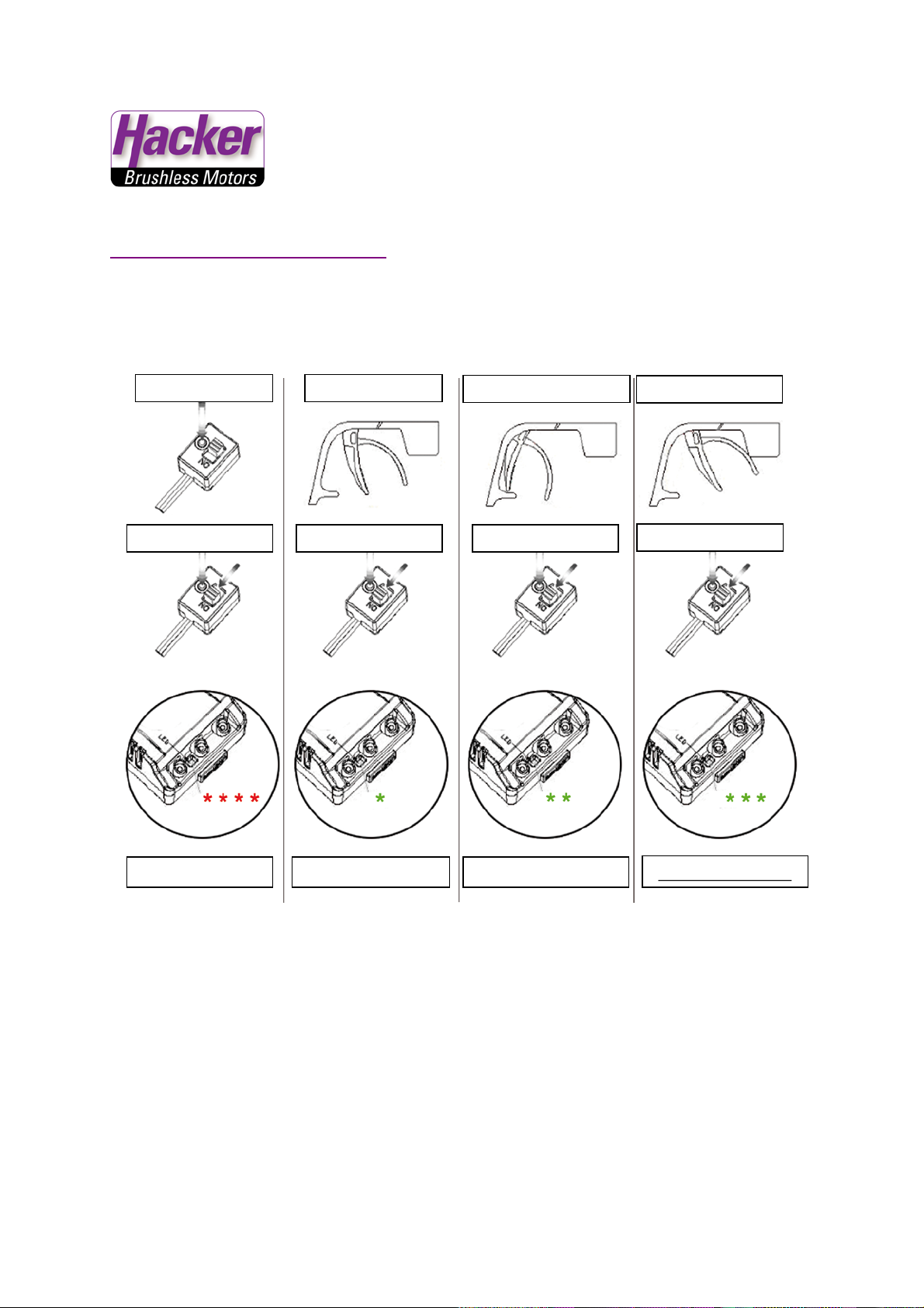
Push Set-Button
Throttle neutral
Throttle full foreward
Throttle full brake
Switch on
Pusch SET
Pusch SET
Pusch SET
LED blincs 4 red
LED blincs 1 green
LED blincs 3 green
LED blincs 2 green
TENSORIC ESC ADITIONAL INFORMATIONEN:
CALIBRATION:
Hacker Motor GmbH
Schinderstraßl 32
D-84030 Ergolding
Tel.: 0049 (0) 871-953628-0
Fax.:0049 (0) 871-953628-29
info@hacker-motor.com
Page 6
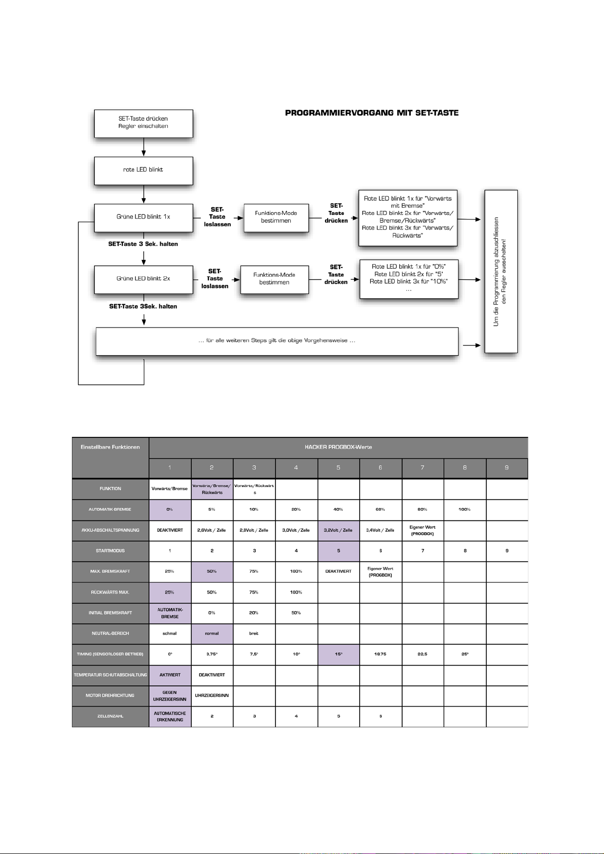
WORKFLOW – PROGRAMMING WITH SET-TASTE:
Hacker Motor GmbH
PROGRAMABLE PARAMETERS:
Grau = Standar deinstellung
Schinderstraßl 32
D-84030 Ergolding
Tel: +49 871-953628-0
Fax: +49 871-953628-29
E-Mail: info@hacker-motor.com
Copyright ©, Hacker Motor GmbH 2010
Irrtum und Änderungen vorbehalten
WEEE-Reg.-Nr. DE 55352581
Copyright 2012 Hacker Motor GmbH. All rights reserved.
 Loading...