

Page 1
Operator Quick Guide
ORBISPHERE 510/511/512
Revision G - 05/11/2008
Page 2
Page 2
About this Guide
The information in this guide has been carefully
checked and is believed to be accurate. However,
Hach Ultra assumes no responsibility for any
inaccuracies that may be contained in this guide.
In no event will Hach Ultra be liable for direct,
indirect, special, incidental, or consequential
damages resulting from any defect or omission in
this guide, even if advised of the possibility of
such damages. In the interest of continued
product development, Hach Ultra reserves the
right to make improvements in this guide and the
products it describes at any time, without notice or
obligation.
Instrument Controls
The instrument front panel provides these user
interfaces:
• A touch screen acting as display, touch
pad and keyboard.
• A LED, showing when instrument is on.
• A buzzer sounds each time the screen is
touched, and when an event alarm is set.
Sound level and type can be adjusted.
Touch Screen
The user interface on the front panel is a 320x240
pixels color display with touch screen. To make
navigation user friendly, the interface software is
Windows CE based, providing easy selection
through menus.
All the measurement, configuration, calibration
and "standard service" routines can be called by
pressing buttons and menus bar on screen.
Measurement display shows one measurement
slope per sensor in function (up to 3 lines for a 3
channel Orbisphere 51x).
Special Keys on Portable Instruments
The sample mode start/stop button starts
the measurement process when in sample
mode. Pressing the button again manually
interrupts the process and an “aborted” message
is displayed in the numeric view.
The state of the battery is indicated at the bottom
of the measurement view. Pressing the battery
icon calls the “Batteries” state window.
Menu Navigation
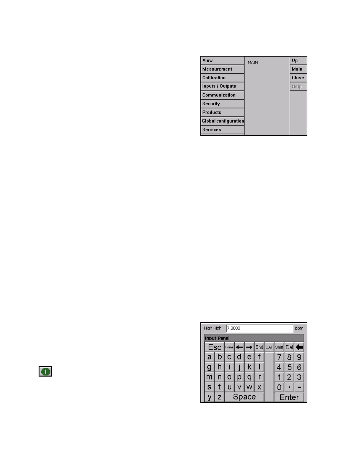
Pressing the “menu” button in the header bar calls
the main menu. The display is made of three
columns:
• Left column is the menus, or submenus
(greyed out options are not available)
• Center column shows a tree view of the
actual position inside the menu structure
• Right column has the following generic
controls:
• Up - Return to a previous menu
• Main - Jump directly to the main menu
• Close - Close the menu and return to
the measurement view display
• Help - Help topics relating to the
current menu
Virtual Keyboard
When a text box (alphanumeric field) has to be
edited and is pressed, a virtual keyboard appears
on screen. It can be used as a PC keyboard
(pressing CAP give access to special keys).
Once values have been entered, press the Enter
key to confirm and exit the virtual keyboard.
Operating Information
Page 3
Page 3
Identification and Authorization Level
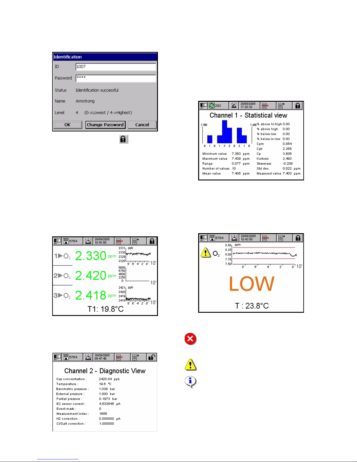
Press the closed padlock icon for two seconds
to open the identification window. The user
identification and password must be entered to
access functionalities authorized by the security
level of the user. By default, security is disabled.
Views
The numeric view is the default view and shows
numeric measurement value identified for each
gas measurement channel available, a graphic
showing measurement value evolution during the
set time frame, and sample temperature.
The diagnostic window contains useful
information for troubleshooting purposes. The
amount of information displayed depends on the
gas measured and the channel configuration.
The statistical view offers statistical data that
matches with Total Quality management tools.
Statistics is a tool to better analyze how a process
behaves.
The statistics are calculated from the data in the
measurement file. The values are updated each
time a new value is added to this file.
Abnormal Conditions
Whenever an abnormal event is encountered, a
sign is displayed on the upper left of the screen.
Pressing on the sign calls a window giving further
details about the actual situation.
There are three levels of abnormal conditions:
Alarm - There is a severe problem causing
the channel to be out of action, and the
system alarm relay to be enabled
Warning - Events less critical than a
system alarm (e.g. measurement alarm)
Information - For information only, no
action is required
Operating Information (cont)
Page 4
Page 4
Continuous Mode vs. Sample Mode
The continuous mode is typically used for process
measurement, whereas sample mode is aimed at
lab measurements of small volume individual
samples such as cans or bottles. The
measurement mode is a parameter defined for
the entire instrument, not for each channel.
In continuous mode, measurements are taken
every 2 seconds. In sample mode, measurements
are initiated by the user when the sample to be
measured has been prepared. TPO or TPA
calculation is only available for portable
instruments in sample mode.
Measurement Mode Configuration
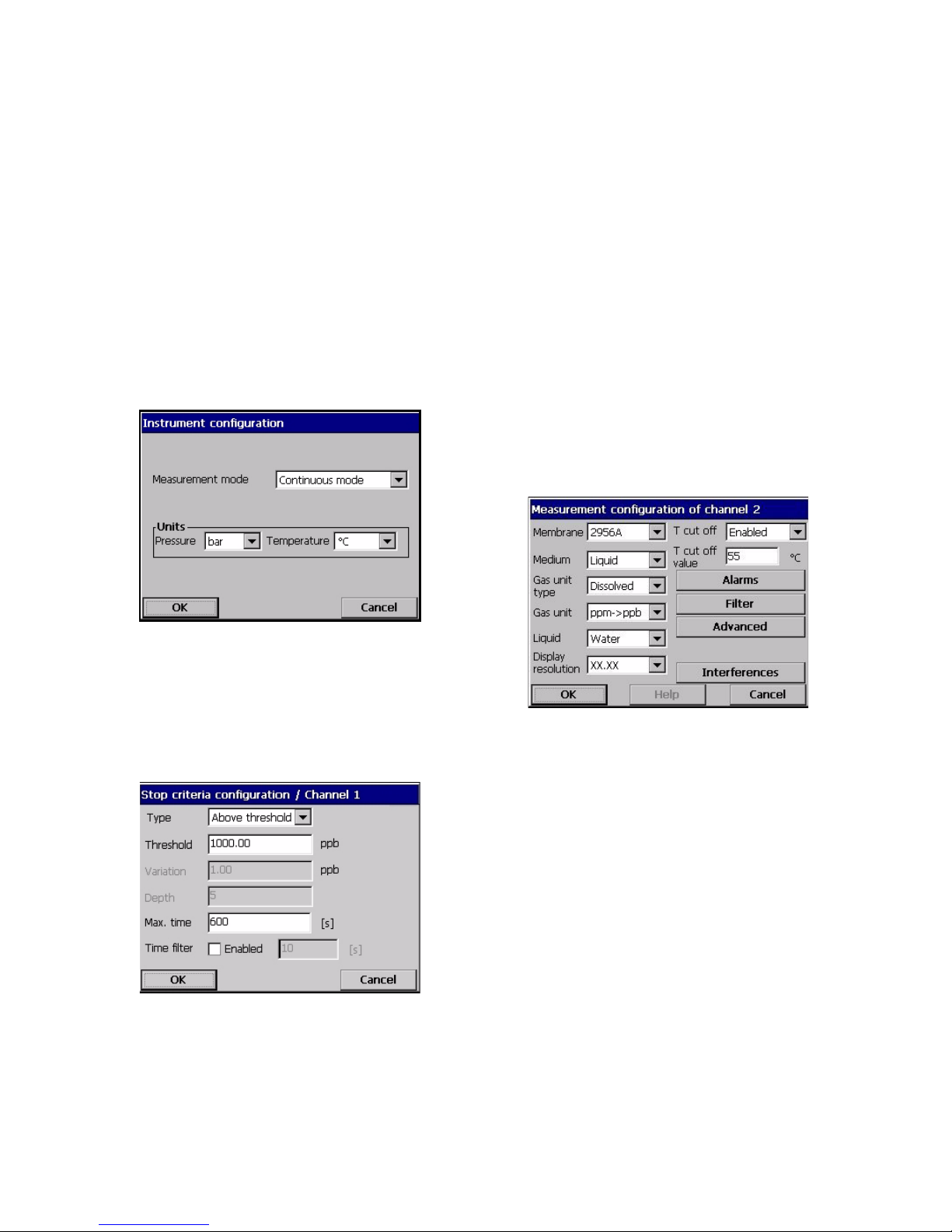
• Measurement mode:
Continuous for on line process
Sample for lab sample analysis (portable
instruments only)
• Selection of units for barometric and
external pressure and temperature
Stop Criteria Configuration (portable only)
Available in sample measurement mode for
configuring the stop criteria for each channel:
• Above threshold: The stop criteria is met
when the gas concentration is greater
than that entered in “Threshold”.
• Below threshold: The stop criteria is met
when the gas concentration is smaller
than that entered in “Threshold”.
• Stability: The stop criteria is met when the
variation of the gas concentration is
smaller than that entered in “Variation”.
• Time: The stop criteria is met when the
elapsed time reaches the “Max. time”
parameter.
The parameter “Max. time” is the maximum time
allowed to reach the target. When this value is
reached the measurement stops.
The “Time filter” allows filtering the stop criteria.
Measurement is stopped when the stop criteria is
fulfilled for a time greater than this parameter.
If TPO or TPA calculation has been enabled, then
when the stop criteria is reached, a screen is
displayed to input the package size and volume of
liquid in the package before computing the TPO
or TPA value.
Measurement Configuration (EC Sensor)
• Sensor’s membrane number selection
• Medium: Liquid or Gas Phase
• Gas unit type: Partial, Fraction, Dissolved
• Gas unit: The list of available units
depends on unit type selected above
• Liquid: When medium is liquid, select
water or a liquid with a different solubility
(if available)
• Display resolution: Maximum resolution
depends on gas, membrane and unit. A
maximum of 5 digits can be displayed.
Decimals can be limited to 0, 1, 2 or 3
decimals for easier reading.
• Thermal cutoff: To protect the sensor, the
thermal cutoff function allows for setting a
sample high temperature limit. If
exceeded the electrical signal to the
sensor is cut off, the measurement
session is suspended and the system
displays a “HOT” alarm message.
Measurement
Page 5
Page 5
Measurement Configuration (TC Sensor)
The measurement configuration for a TC sensor
is same as for an EC sensor with the addition of
one extra selection criteria:
Purge gas: From the drop-down list, select the
purge gas being used for the TC sensor.
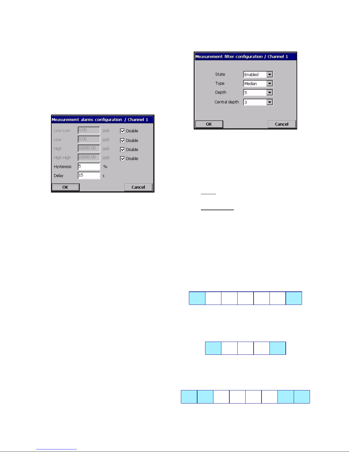
Measurement Alarms Configuration
Set the thresholds for the low/high concentration
levels, according to the application. Each alarm
type can be individually enabled or disabled
without losing its settings. These events can
activate the relays and can be displayed.
• Low-low: 2nd stage for too low
concentration
• Low: 1st stage for too low concentration
• High: 1st stage for too high concentration
• High-high: 2nd stage for too high
concentration
• Hysteresis in % of above set values. The
hysteresis is used to prevent relay
“flickering” when the measurement is just
at the alarm levels. Set this to a
minimum, but enough to eliminate
flickering
• Delay in seconds before alarms go on
whenever concentration values are
above ”High alarms” or below “Low
alarms”. Set this to a minimum, but
enough to avoid alarms for non
representative peaks beyond the set
level.
Measurement Filter Configuration
The filters are aimed at “flattening” the
measurement curve in situations where the
process shows atypical peak values that could
otherwise hamper the interpretation of
measurement readings. The filter is applied on
the last set of measurements each time a
measurement is taken.
• Mean
: Mathematical average of the last
set (depth) of measurement values.
• Median filter
: Allows for eliminating
atypical peak measurement values, and
averages the remaining ones. The
calculation sorts the last measurements
set (depth) by values, then deletes the
highest and lowest values, and averages
the remaining values (central depth)
Example for depth 7, central depth 5:
Sorted values, both ends eliminated, the average
of the center five is then 3.88.
Example for depth 5, central depth 3:
Sorted values, both ends eliminated, the average
of the center three is then 4.23.
Example for depth 8, central depth 4:
Sorted values, both ends eliminated, the average
of the center four is then 4.43.
Measurement (cont)
0.7 1.1 4.0 4.3 4.4 5.6 7.0
1.1 4.0 4.3 4.4 5.6
0.7 1.1 4.0 4.3 4.4 5 5.6 7.0
Page 6
Page 6
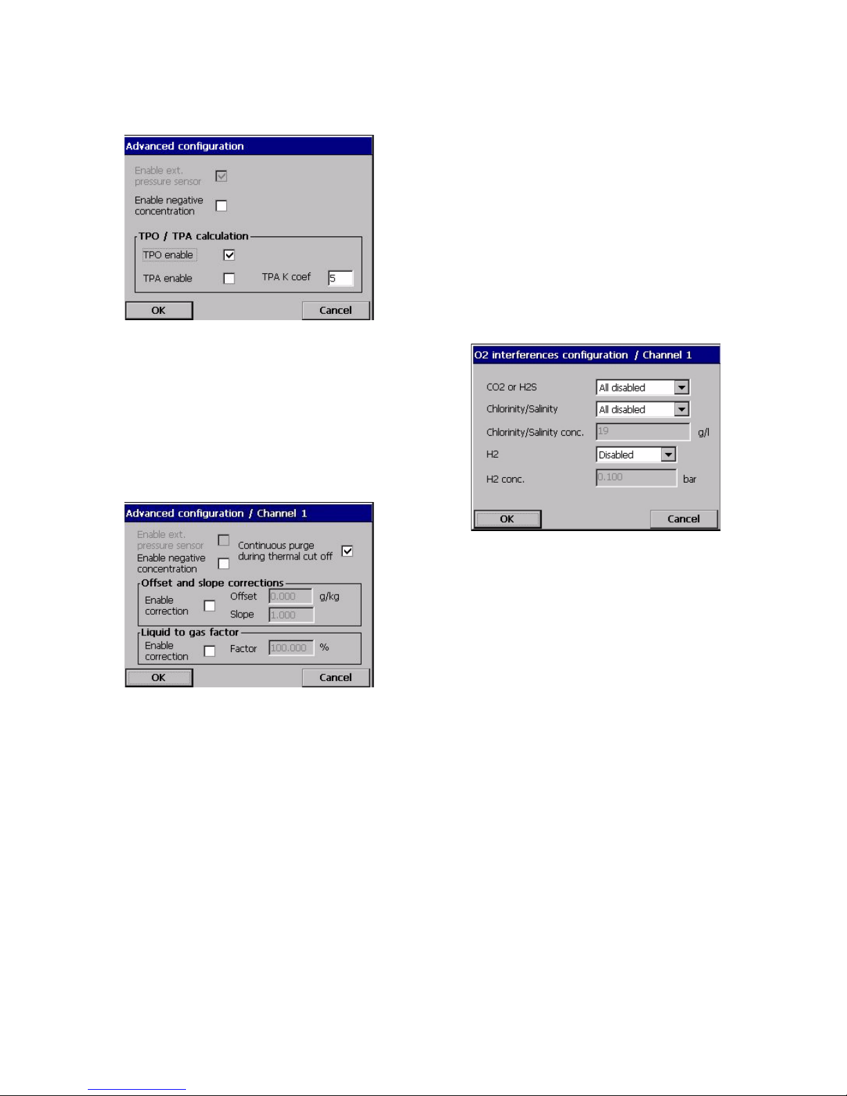
Advanced Configuration (EC Sensor)
• Enable ext. pressure sensor: Check as
appropriate
• Enable negative concentration: Check as
appropriate
• Enable TPO or TPA calculation: Check if
required (portable instrument only)
Advanced Configuration (TC Sensor)
• Enable ext. pressure sensor: Check as
appropriate.
• Enable negative concentration: Check as
appropriate.
• Continuous purge during thermal cut off:
If thermal cutoff has been enabled, then
check this box to ensure that a
continuous purge of the TC sensor takes
place while the measurement session is
suspended due to the thermal cutoff
temperature value being exceeded.
• Offset and slope corrections: Enable
correction as appropriate.
• If enabled, the correction values for offset
and slope must be entered. These values
cannot be negative.
• Liquid to gas factor: Enable correction as
appropriate.
• If checked, the percentage correction
factor must be entered. This value cannot
be negative.
Note :
To manually set the TC sensor into a continuous
purge mode, press the Continuous Purge
button that is available from the Services -
Diagnostic - Channel x - Amplifiers menu.
Interferences Configuration (EC Sensor)
These options are available to take into account
the influence of some components or gases in the
sample during the measurement. By default all
available interference corrections are disabled.
•Select CO
2
, H2S or All disabled
depending on the type of sensor and
application.
• Select Chlorinity, Salinity or disabled. For
chlorinity and salinity, enter the actual
concentration in the sample.
•Select H
2
enabled or disabled. If
enabled, enter the interfering gas
pressure (the partial pressure of H
2
in the
sample).
Note :
When enabled, the H2 interference must be
calibrated. A warning pop-up window is displayed
to remind the user for this action.
Measurement (cont)
Page 7
Page 7
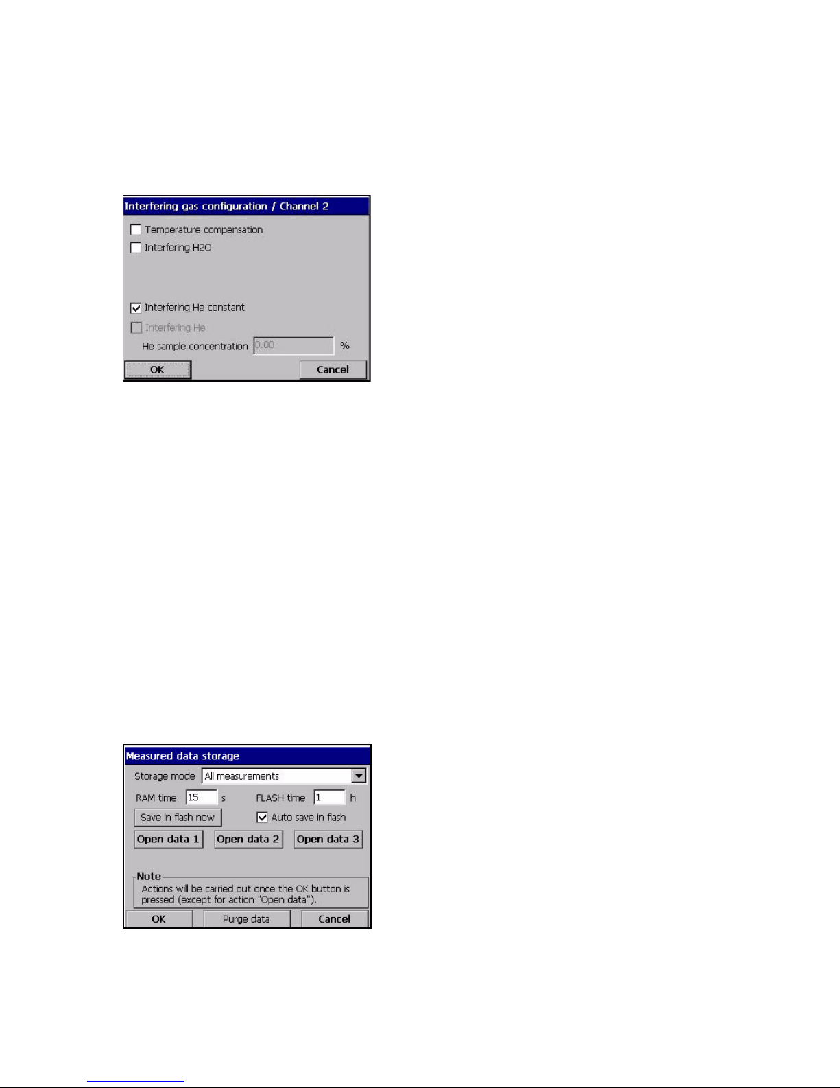
Interferences Configuration (TC Sensor)
A number of different interfering gas options are
available (temperature, H
2
O, He, O2 and H2),
depending on the instrument configuration and
the gas being measured.
• Temperature compensation: If there is a
significant fluctuation in the sample
temperature enable temperature
compensation to reduce the influence of
these temperature fluctuations.
• Interfering H2O: This only applies to
measurements taken in 100% humid
gases or in traces of dissolved gas in
water. It allows a correction to the slope
and temperature coefficients calculated
during calibration.
• Interfering gas: Enable this option to
allow the instrument to correct for the
presence of specific gases in the sample.
If the interfering gas is helium, you can
enter the concentration percentage if
known.
Measured Data Storage
There is one measurement file per channel which
contains the data generated by the measurement
cycle. The current measurement files are updated
in volatile memory, and are regularly copied in
non-volatile memory (file back-up). At start up, the
measurement files in volatile memory are updated
with the files from the non volatile memory.
Adjust the parameters for recording and storing
measured data. Two storage mode selections are
available depending on the measurement mode
selected:
Continuous measurement mode:
• No storage
• Store once: When volatile memory is full
(10,000 positions), measurement
recording stops
• Rolling buffer: When volatile memory is
full, the latest measurement set replaces
the oldest (first-in, first-out basis)
Sample measurement mode:
• Only final measurement: The
measurement when the stop criteria are
met is saved (one per sample)
• Only when sample mode started: The
measurements when the sample mode is
started are saved
• All measurements: All measurements
stored continuously
Additional parameters:
• RAM time (volatile memory): Delay in
seconds between two recordings of
measured data.
• FLASH time (non-volatile memory):
Delay in seconds between two data file
transfers from volatile memory into nonvolatile memory. Last data file erases
previous one.
Buttons:
• Purge data: Clear all data in the volatile
and non-volatile memories
• Start logging measurement: In store once
mode, starts and stops the measurement
recording session. Measurement
recording is stopped when buffer is full
• Open data 1,2, or 3 (and TPO or TPA
data if enabled): Opens the table
showing the measured value which are
stored in the volatile memory (RAM)
Measurement (cont)
Page 8
Page 8
General
We define 2 types of calibration:
• the calibration of the gas to measure
• the calibration of interferences
To calibrate the gas to measure (main gas), the
user usually puts the sensor in the main gas
without any interfering gas.
To calibrate the interferences, the user usually
puts the sensor in the interfering gas without any
of the main gas.
Calibrations can only be performed once the
instrument has been installed, configured and
each channel has been set up. You must also
ensure that you have the correct access rights to
access the calibration menu.
Select Sensor calibration from the calibration
menu, and then select which channel must be
calibrated (option).
There are two types of gas sensor calibration
available, depending on the gas being measured
and the type of sensor in use:
1) In Air: For Oxygen and Ozone
2) Direct value: Any gas. This calibration
exposes the sensor to a gas with a
known partial pressure, or a liquid
sample with a known gas
concentration.
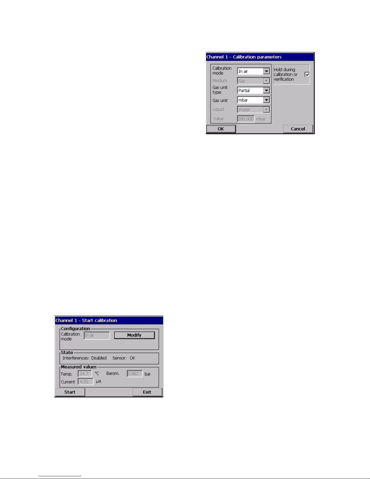
EC Gas Sensor Calibration
Calibration of the Measured Gas
Before initiating a calibration process, the
calibration parameters must be set by pressing on
the Modify button. Last calibration parameters
are memorized, so this step can be ignored if
correct parameters are already set.
Modify Calibration Parameters
• Calibration mode: 2 types available,
depending on the gas being measured:
• Direct value: Any gas
• In Air: For O
2
or O3 (default)
• Medium: Select liquid or gas (direct
calibration only)
• Concentration unit type: Partial, fraction
or dissolved (dissolved is for calibration
in a liquid only)
• Concentration unit: The list of available
units depends on unit type selected
above.
• Liquid: Select as appropriate, available
when liquid has been selected in medium
(above).
• Enter the gas concentration according to
value in the calibration media, when
direct value is used
• Hold during calibration: On by default,
this stops any output from the instrument
during the calibration process to avoid
sending invalid information to any
connected device.
• Interference enabled: If selected, this
takes into account the influence of
interferences during calibration. By
default the same interferences as during
measurement is selected
Press OK to start calibration
Calibration
Page 9
Page 9
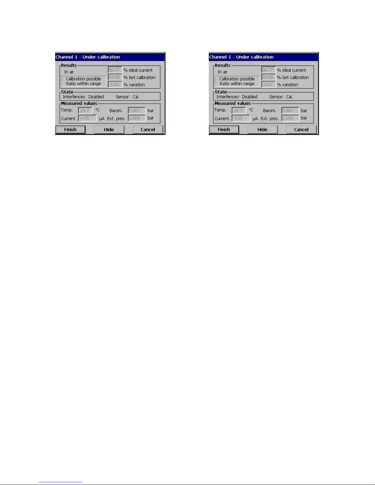
Calibration Results
A calibration screen will be displayed showing
current measurement data which is continually
refreshed.
The value “% ideal current” is a percentage of the
current against the ideal current for the
membrane type selected. If this percentage is not
within the accepted range, an error message is
displayed and the calibration process fails. A
warning message can be displayed when this
value is close to the boundaries, but when
calibration can be accepted.
The message is first displayed in the result box.
The dialog box with the error message or the
warning is displayed when the finish button is
pressed.
The value “% last calibration” shows the ratio
between current measurement and the previous
sensor calibration.
The value “% variation” indicates the variation
during the last 3 measurements, which is the
stability of the measurements. A variation as low
as possible is needed for a precise calibration
The display shows the actual calibration
parameters, and the actual readings
(temperature, barometer, current).
In case of a calibration failure, consider replacing
the membrane. See the EC Sensor Maintenance
Manual for details.
Verification
Similar to the calibration procedure, but for
verification of the actual calibration values. The
result of the measurements made during the
verification is not stored and the actual calibration
data is not modified.
O
2
Sensor Calibration
The sensor is in contact with either:
• Air at atmospheric pressure (In Air)
•O
2
at known concentration (Direct value).
O
2
In Air Calibration
This calibration procedure places the O2 sensor in
water-saturated air, to provide a known oxygen
reference against which to calibrate.
Dry the sensor thoroughly, before placing the
sensor storage cap under tap water. Shake off
any excess water, but leave a few drops inside
the cap. Verify that the screw-on protection cap is
in place on the sensor head.
Then, loosely place the storage cap back on the
sensor, holding it in place with a few turns of its
collar.
Set the calibration parameters accordingly and
press calibrate.
O
2
Direct Calibration
This procedure calibrates the oxygen sensor
against a liquid sample containing a known level
of dissolved O
2
flowing through the sample line.
The instrument displays the sensitivity of the
sensor as a percentage of the sensitivity
determined when calibration was last performed.
Set the calibration parameters accordingly and
press calibrate.
Calibration (cont)
Page 10
Page 10
O
3
Sensor Calibration
The sensor is either in contact with:
• Air at atmospheric pressure (In Air)
•O
3
at known concentration (Direct Value).
The procedure is the same as for the O
2
sensor.
In the case of the "In air" calibration, the sensor
measures O
2
during calibration. The O
3
coefficient is deduced taking into account how the
sensor behaves in O
2
.
As a different voltage is used at the anode to
measure O
2
and O3, the O3 measurement takes a
long time to stabilize. To facilitate the follow up
after an "O
3
in air" calibration, negative values
can be displayed.
H
2
Sensor Calibration
The recommended method is at known
concentration (Direct value). The gas can be pure
H
2
or a mixture of H2 with an inert gas (e.g. a
mixture of H
2/N2
). The known concentration is
entered by the user in the calibration parameter
window. The sensor is in contact with calibration
gas (Direct Value) in gas phase at atmospheric
pressure.
Make sure the H
2
concentration used for
calibration is within the acceptable range for the
membrane.
TC Gas Sensor Calibration
Calibration of the Measured Gas
Before initiating a calibration process, the
calibration parameters must be set by pressing on
the Modify button. The last calibration
parameters are memorized, so this step can be
ignored if the correct parameters are already set.
Similarly, if only the calibration value has
changed, then this can be updated directly
instead of pressing the Modify button.
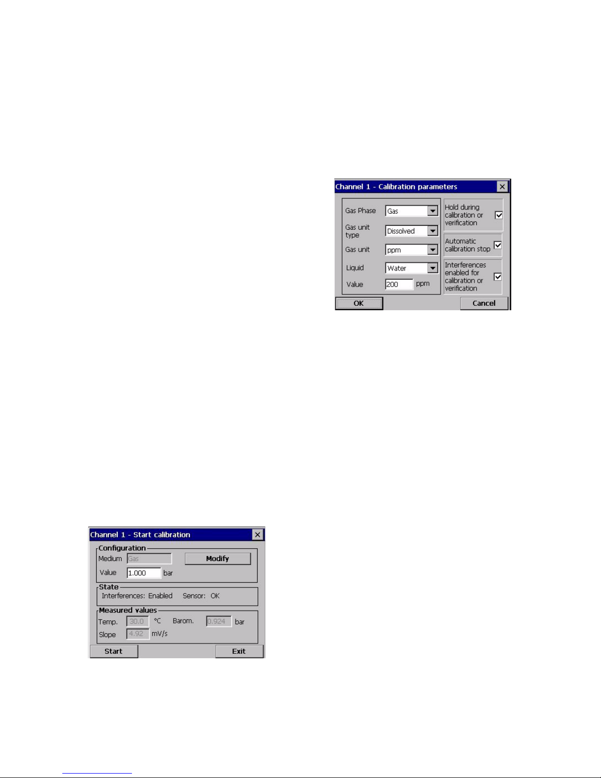
Modify Calibration Parameters
• Gas Phase: Select liquid or gas (direct
calibration only)
• Gas unit type: Partial, fraction or
dissolved
(dissolved is for calibration in a liquid
only)
• Gas unit: The list of available units
depends on unit type selected above.
• Liquid: Select as appropriate.
• Enter the gas concentration according to
the value in the calibration media.
• Hold during calibration: On by default,
this stops any output from the instrument
during the calibration process to avoid
sending invalid information to any
connected device.
• Automatic calibration stop: If selected,
when the stability criteria is reached, the
calibration process stops automatically.
• Interferences enabled: If selected, this
takes into account the influence of
interferences during calibration. By
default the same interferences as during
measurement are selected.
Press OK to start calibration
Calibration (cont)
Page 11
Page 11
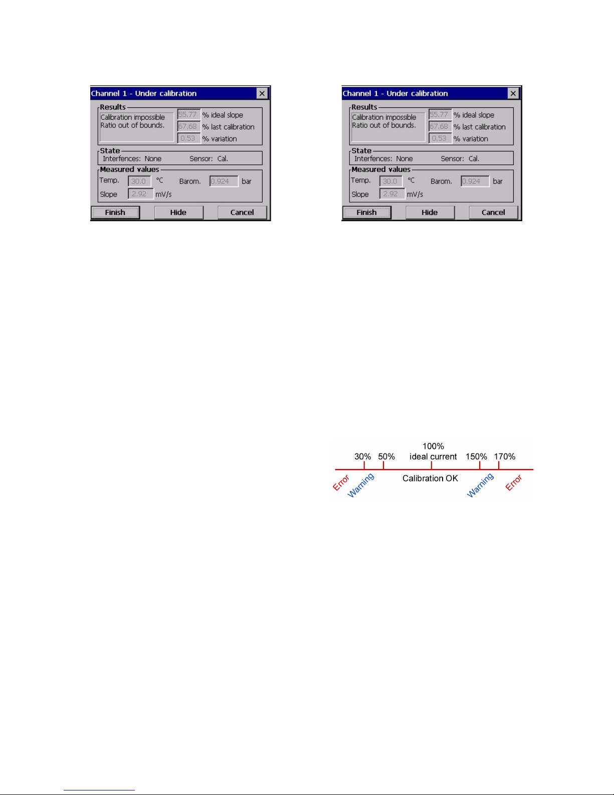
Calibration Results
A calibration screen will be displayed showing
current measurement data which is continually
refreshed.
The value “% ideal slope” is a percentage of the
slope against the ideal slope. If this percentage is
not within the accepted range, an error message
is displayed and the calibration process fails. A
warning message will be displayed when this
value is close to the boundaries, but when
calibration can be accepted.
The message is first displayed in the result box.
The dialog box with the error message or the
warning is displayed when the finish button is
pressed.
The value “% last calibration” shows the ratio
between the current measurement and the
previous sensor calibration.
The value “% variation” indicates the variation
during the last 3 measurements, which is the
stability of the measurements. A variation as low
as possible is needed for a precise calibration.
The display shows the actual calibration
parameters, and the actual readings
(temperature, barometer, slope).
In case of a calibration failure, consider replacing
the membrane. See the TC Sensor Maintenance
Manual for details.
Verification
Similar to the calibration procedure, but for
verification of the actual calibration values. The
result of the measurements made during the
verification is not stored and the actual calibration
data is not modified.
Calibration Errors (EC and TC sensors)
Calibration is not possible:
• When "ratio ideal current" is greater than
170% or smaller than 30%
• When sensor cannot measure
• When "ratio ideal current" is greater than
150% or smaller than 50%, a warning is
displayed but calibration is valid
Calibration (cont)
Page 12
Page 12
Interference Calibration (EC Sensor)
The hydrogen interference calibration is available
for EC sensors measuring O
2
concentrations, and
is required when H
2
interference has been
enabled. The lower part of the screen displays the
actual measurement.
• Enter in the upper box the purity of the
hydrogen that is used for this calibration.
A reasonably pure (e.g. 99.8% or better)
hydrogen source and an accurate
pressure gauge are needed.
• Hold during calibration: Selected by
default, this holds the measurement
sequence to avoid storing invalid values.
Instructions
Using a flow chamber, expose the sensor to the
H
2
source at the same barometric pressure that is
shown on the display. Press Start to initiate the
H
2
interference calibration.
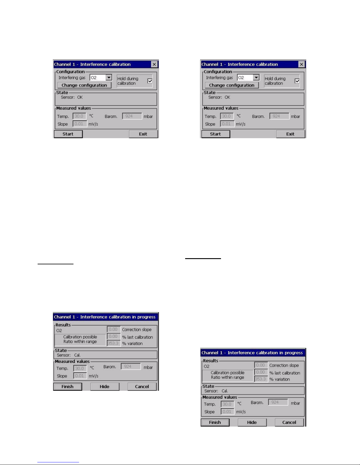
Interference Calibration (TC Sensor)
This calibration is available for TC sensors and is
required when one of the interferences has been
enabled. The lower part of the screen displays the
actual measurement.
• Select from the interfering gas to be
calibrated from those available, or press
the Change configuration button to
reconfigure.
• Hold during calibration: Selected by
default, this holds the measurement
sequence to avoid storing invalid values.
The following instructions refer to the different gas
interference combinations:
Instructions
For interfering oxygen on measured hydrogen or
nitrogen, expose both sensors to ambient air, or a
100% oxygen source, and press Start to initiate
the calibration.
For interfering hydrogen on measured oxygen or
nitrogen, expose both sensors to a 100%
hydrogen source and press Start to initiate the
calibration.
Calibration (cont)
Page 13
Page 13
Calibration Reports
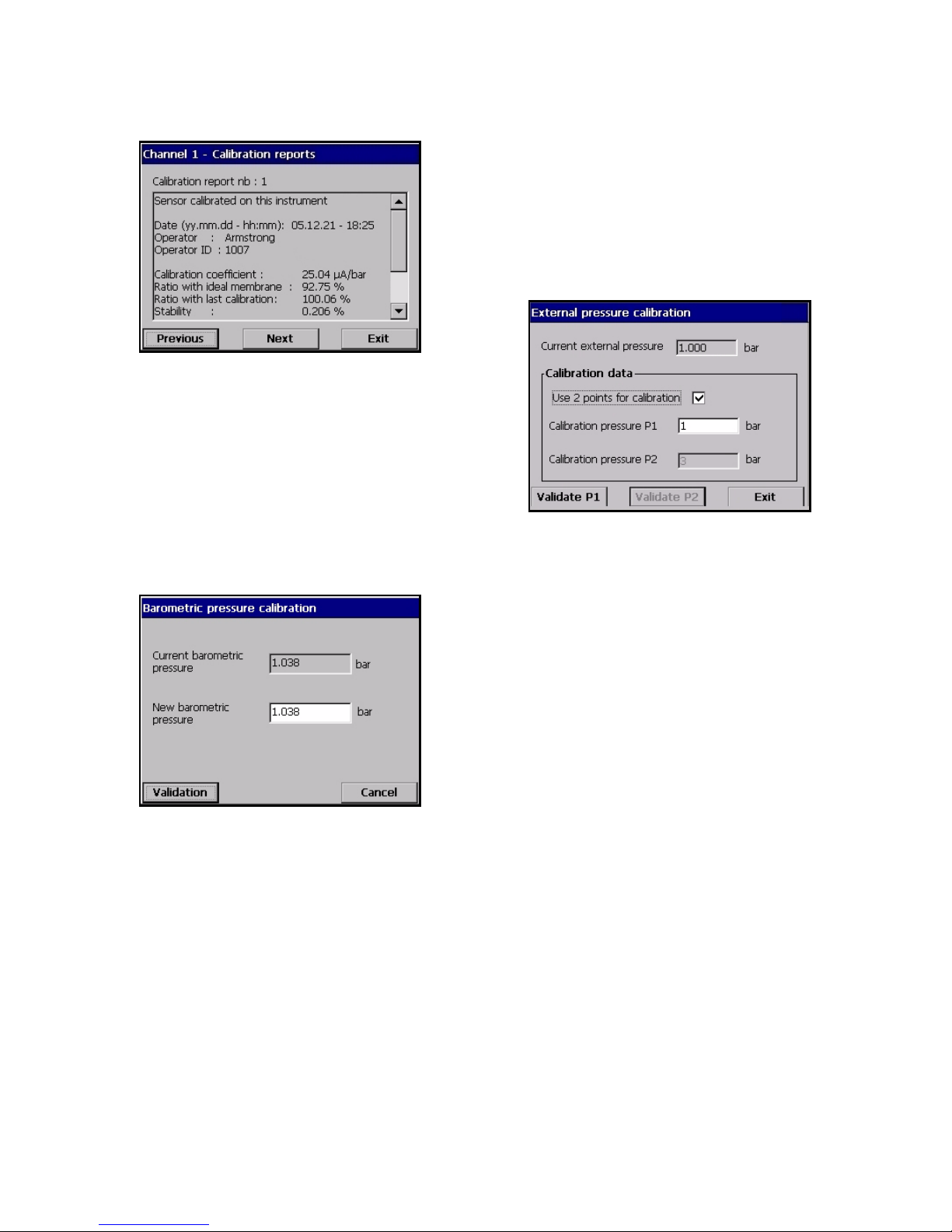
Once a measured gas calibration is completed, a
report is issued showing the log file of the last
actions. The calibration report will contain the
data for the last 50 calibrations. Each calibration
record will contain parameters useful for
traceability.
For interfering gas calibration reports, you will be
asked to select the interfering gas from those
available.
Barometric Pressure Calibration
Upper box shows the barometric pressure
measured by the instrument.
Using a precision certified barometer, measure
barometric pressure in the location where the
measuring instrument is used. Compare the
values; if values are the same press cancel;
otherwise enter the new barometric value in the
lower box and validate the new setting.
External Pressure Calibration (optional)
Two calibration methods for the external pressure
sensor can be selected:
• Two point calibration (recommended)
• One point calibration
By default the two point calibration is selected.
Two Point Calibration (recommended)
Connect a certified absolute pressure gauge to
the sample line, and use a certified precision
barometer.
• The two point calibration starts with
barometric pressure for the lower point.
Expose the external pressure sensor to
the atmosphere. Enter the barometric
pressure read on the barometer in the
upper window and validate P1.
• Expose the external pressure sensor to
line pressure, making sure it is exposed
to the same pressure as the certified
absolute pressure gauge. Enter the
absolute pressure value read on the
certified absolute pressure gauge in the
lower box, and validate P2.
One Point Calibration
Connect a certified absolute pressure gauge to
the sample line.
• Expose the external pressure sensor to
line pressure, making sure it is exposed
to the same pressure as the certified
absolute pressure gauge. Enter the
absolute pressure value read on the
certified absolute pressure gauge in
lower box, and validate P1.
Calibration (cont)
Page 14
Page 14
Services
A number of maintenance and diagnostic options
are available from the Services menu.
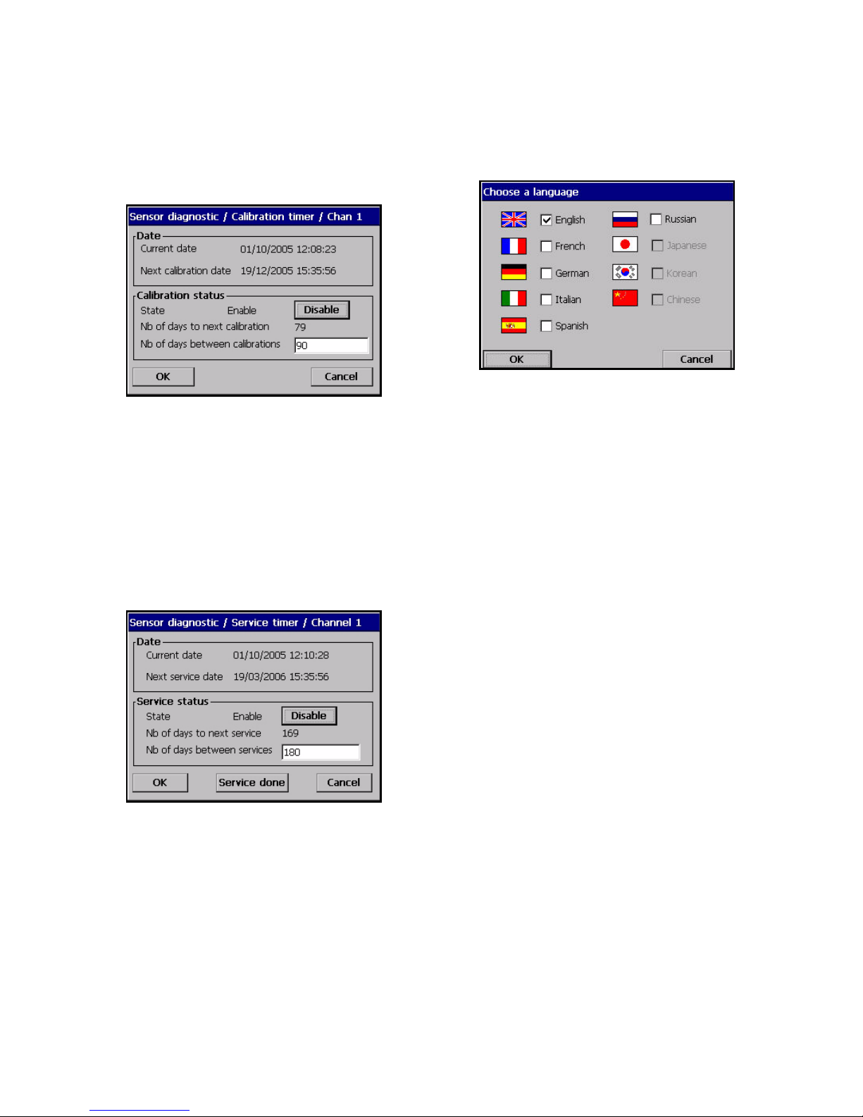
Sensor Diagnostics - Calibration Timer
The instrument can automatically remind the user
when the next sensor calibration is due. Select
the channel, enable it and enter a delay in days.
The display shows current instrument date and
time, next calibration due date and time, and the
remaining days.
The next calibration date is updated when the
sensor is calibrated.
Sensor Diagnostics - Service Timer
The instrument can automatically remind the user
when the next sensor service is due. Select the
channel, enable it and enter a delay in days. The
display shows current instrument date and time,
next calibration due date and time, and remaining
days.
The next service date is updated when the button
Service done is pressed after a service.
The sensors attached to your instrument will
require periodic servicing and maintenance. For
more information on this, please refer to the
manual(s) delivered with your sensor(s).
Language
Check the language as required and restart the
instrument to apply the change. The instrument
will restart in the selected language.
Other Options
These include:
• Time/Date - Used to set the time, date
and the display settings
• Screen - Used to set the screen contrast
• Buzzer - Used to set the alarm
parameters (sound, volume, etc.)
• Main board info - Displays instrument
model, ID and software version
• Batteries - On all instruments this
display gives the real time clock battery
charge level and voltage. On portable
instrument there is a battery level
indicator for the main batteries.
Instrument Maintenance
Any instrument maintenance should be carried
out by a qualified Hach Ultra Service Technician.
Please contact your local representative should
you feel any maintenance or instrument
adjustments are required.
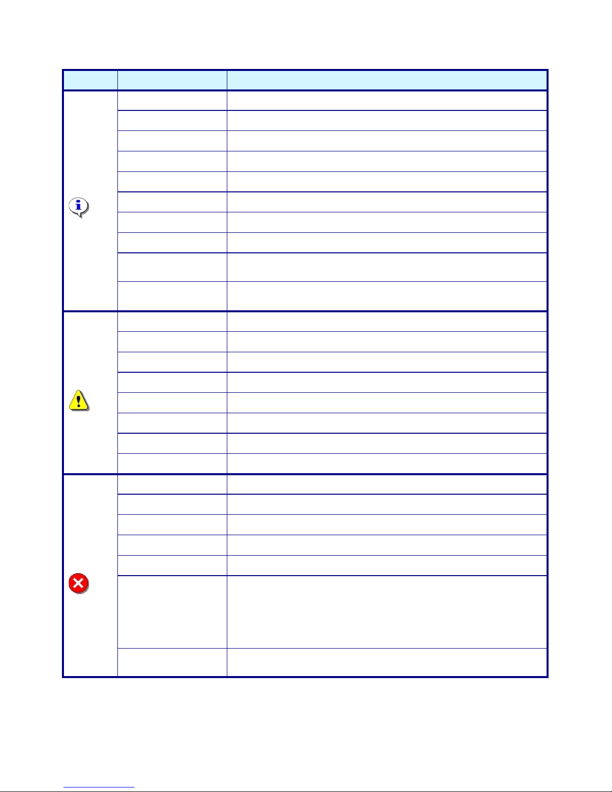
Troubleshooting - List of Events
The possible events, along with the text message
displayed on the instrument numeric view screen,
the reason for the event and its criticality are listed
in the following table.
Maintenance and Troubleshooting
Page 15
Page 15
Maintenance and Troubleshooting (cont)
Typ e Name Description
Information
Measure Normal measurement mode.
Filter enabled The gas measurements are filtered.
Sample measurement The sample measurement is started.
Meas. not ready The measurement is not ready (e.g. at startup)
Autotest in progress The autotest is running.
Autotest failed The autotest has failed.
Alarm snooze The alarm snooze is ON.
Sample mode user aborted The sample mode has been stopped because the user has pressed the stop button.
Sample mode stopped
because of time out
The sample mode has been stopped because the maximum time to reach the target
has elapsed.
Sample mode stopped
because of an error
The sample mode has been stopped because of a measurement error (sensor out,
purge failure, etc.).
Warning
Calibration Channel in calibration.
Hold The measurement is frozen.
Alarm low low The gas concentration is below the Alarm LowLow limit.
Alarm low The gas concentration is below the Alarm Low limit.
Alarm high The gas concentration is above the Alarm High limit.
Alarm high high The gas concentration is above the Alarm HighHigh limit.
Calibration required The calibration of the sensor is required.
Service required The sensor requires a service.
Alarm
Channel disabled The channel has been disabled.
Channel out The measurement board has been disconnected (or does not answer).
Sensor out The sensor has been disconnected.
Ext. pressure sensor out The external pressure sensor is out.
Thermal cut off The temperature is above the thermal cut off.
Interfering gas error
For this channel, an interfering gas is taken into account (i.e. O
2
over N2). This
interfering gas is measured by another channel. This event occurs when the
other channel:
• is in error (sensor out, thermal cut off, calibration, etc.)
• does not exist anymore
• does not measure the right gas (i.e. O
2
).
PROFIBUS-DP value not
updated
The PROFIBUS-DP module has not received measurements from the instrument for
30 seconds.
Page 16
 Loading...