

Operator Quick Guide
ORBISPHERE 3624
Revision F - 03/10/2008

Page 2
About this Guide
The information in this guide has been carefully
checked and is believed to be accurate. However,
Hach Ultra assumes no responsibility for any
inaccuracies that may be contained in this guide.
In no event will Hach Ultra be liable for direct,
indirect, special, incidental, or consequential
damages resulting from any defect or omission in
this guide, even if advised of the possibility of
such damages. In the interest of continued
product development, Hach Ultra reserves the
right to make improvements in this guide and the
products it describes at any time, without notice or
obligation.
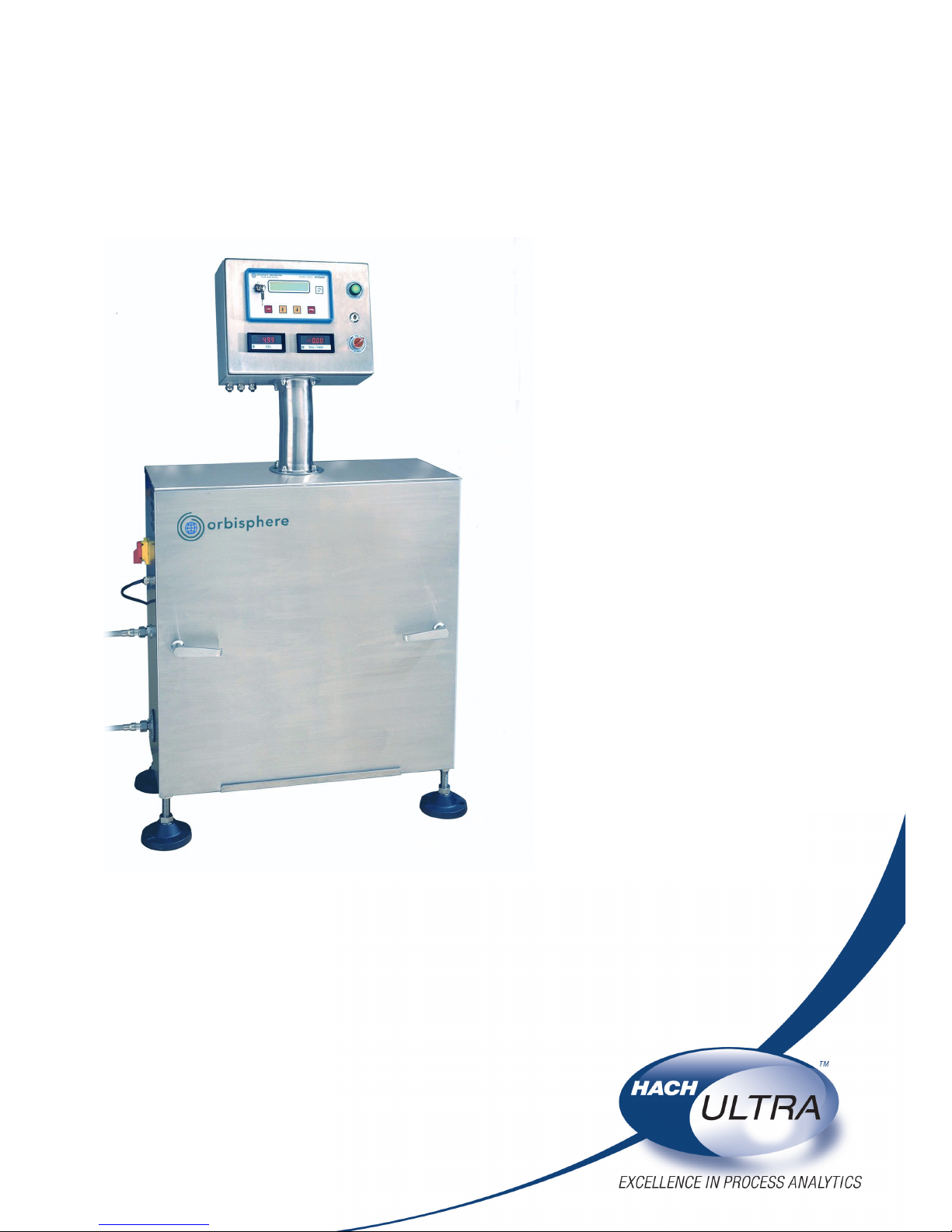
Instrument Controls
The front panel of the 3624 ProBrix Plus
instrument has several displays and controls.
The Power Switch and Pump Switch are used
to turn the instrument or pump on/off respectively.
The CO
2
and °brix-%diet LED displays are
driven by analog outputs from the instrument.
The Key Switch should be turned to the
horizontal unlocked position to start the
instrument in measurement mode. The function
keys are only active if the key switch is in the
unlocked position. Use the vertical locked position
to avoid accidental modifications.
The Display has a two-line liquid crystal display
(LCD) with 16 characters per line.
A Light Button, when pressed, provides
illumination to the LCD for three minutes.
Four Function Keys provide simple operator
control over the instrument functions:
• ESC jumps back a step within a program
menu.
• The × Ø keys are used to scroll through
screen displays.
• ENTER selects a highlighted item from
the menu.
Main Menu
The operator controls the instrument by menuselectable commands using the four function
keys. The main menu has three choices:
• MEASURE to start the measurement
sequence.
• OPTIONS to enable the instrument to be
customized.
• CALIBRATE to provide a choice of
sensor calibration procedures.
To select one of these commands, first press ESC
until the main menu is displayed (as illustrated
above), next press the × Ø keys until your choice
is flashing, and then press ENTER.
Entering Values
When entering numbers in any of the instrument
menus, the current numerical value is displayed
with one digit highlighted by the ^ symbol below it.
Use the × Ø keys to increase/decrease the value
of the digit (0-9 plus a decimal point) until you
reach your required target value.
Press ENTER to shift the highlight symbol one
digit to the right and repeat the process. Pressing
ENTER after the last digit saves the value.
Operating Information
Page 3
Switching on the indicating instrument first shows
the software version and date on the LCD, and
then switches to a Configuration Display
showing the gas being measured, the purge gas
required for the CO
2
sensor, and the membrane
model number for this sensor.
A configuration
screen appears
briefly, before
switching to a
Calibration
Coefficients screen for several seconds before
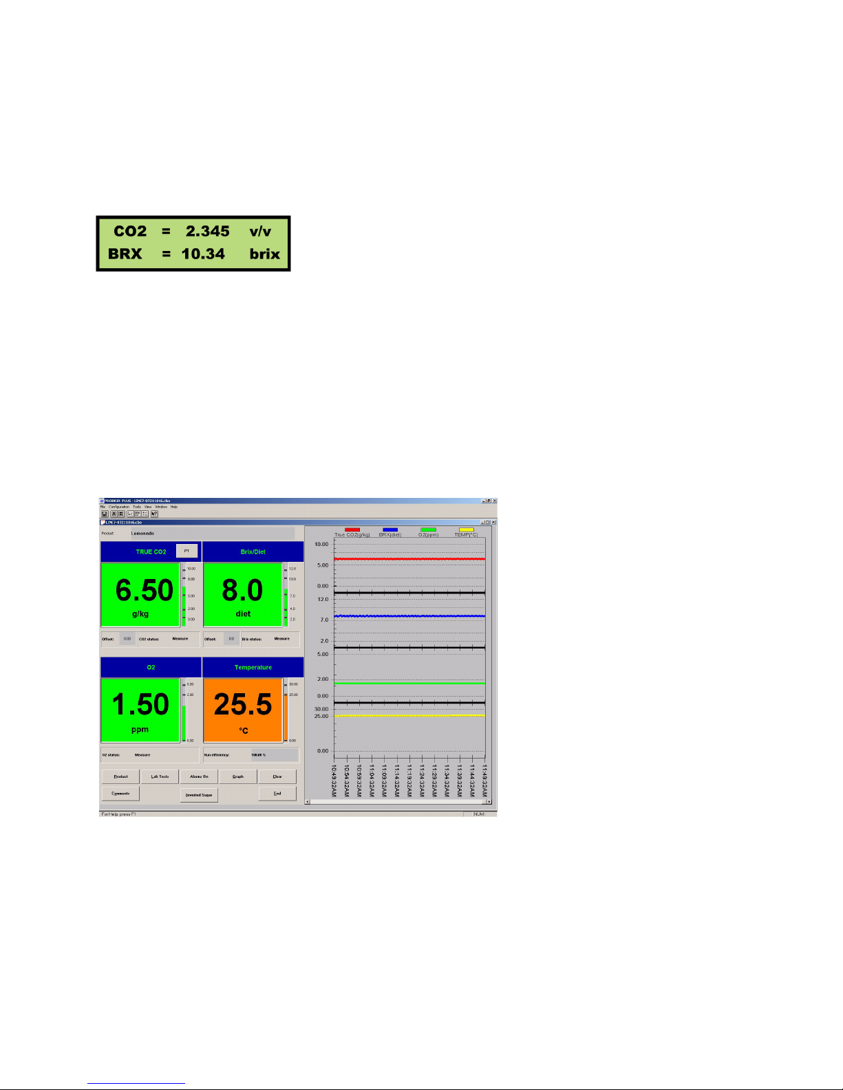
finally switching to an O2 Measurement Display.
This display then alternates every few seconds
with one of the CO
2
or °Brix/%Diet measurement
displays (illustrated left).
Press the × Ø keys to switch between these
three measurement displays. You may
experience a delay before the display changes,
depending on the purge/measurement cycle of
the CO
2
sensor. Press the ESC key to exit from
these displays and move to the Main Menu.
The O
2
and Brix/Diet LED displays are driven by
analog outputs from the instrument. These
displays are updated at regular time intervals but
may vary slightly from the instrument LCD's
displayed values.
Measurement - Instrument
Measurement - PC
Once the ProBrix Plus PC Program software is installed on your PC, it is recommended that no screen
savers are set and that the PC is not switched off unless absolutely necessary.
The PC Program maintains a window for each active LINE, which are activated via the Start Line A/B
command in the Configuration menu, or by the A/B buttons on the toolbar at the top left of the screen.
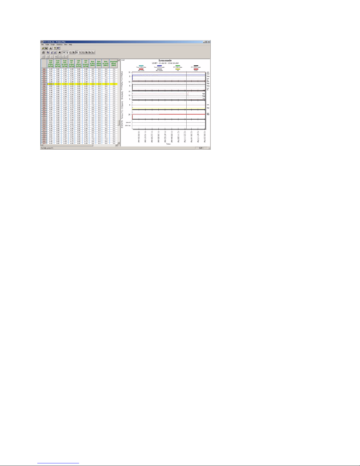
The Numerical Indicator Panel
shows information relating to the last
measurement, and is divided into
four, containing the CO
2
data, the
Brix/Diet data, the O
2
data and the
temperature information. For each of
these, the units of measurement, the
most recent measurement value and
a vertical bar graph are shown.
The background colors show:
•GREEN measurements are within
High and Low limits
•ORANGE measurements are
outside High or Low limits, but inside
High/High and Low/Low limits
•RED measurements are outside
High/High or Low/Low limits or an
error has occurred
The Status Panel is displayed below the indicator panel and shows the status for CO
2
, Brix/Diet and O
2
indicating Standby, Measure or Fault.
The Graphic Panel contains four charts showing the measurements over a one-hour period. Any onehour period within the last 7½ hours can be viewed using the horizontal scroll bar. The lines on the graph
are color-coded as per the description at the top of the panel. Placing the mouse cursor over a data point
on the graph will cause the cursor to change to a hand symbol. Clicking the mouse when the hand
symbol is visible will cause a message box to appear giving the values of the measurements, including
the time they were taken.
The Buttons Panel at the bottom of the window contains eight additional options.
Page 4
File Menu
This menu contains a standard list of File options
to allow you to open a file of historical data. When
selecting this menu, the four most recently
accessed files are listed.
Opening a file will display the initial screen
showing data in either tabular or graphical format,
or a combination of the two. You can resize these
areas by dragging the slider bar left or right with
the mouse, or alternatively using the Split
command in the View Menu.
Any changes you make can then be Saved from
this menu, as well as being saved to a different file
using the Save As option. You can also use the
Print Setup option to set up the printer you wish
to use during the process for any hard-copy
output. The Properties option allows you to view
standard information about the file and product.
Table Menu
While in the Table Window, you can right click the
mouse for quick access to some of the Table
Menu options.
A copy option lets you select table contents as a
text file and copy them to the clipboard for pasting
into other applications (e.g. Excel). The search
option allows you to search for a specified alarm
or event chosen from a drop-down list.
You can change what measurements are
displayed in the table, the formatting for the
numerical values and color options for highlighted
rows. Also, you can adjust the default and sizes of
selected rows or columns, and define the
measurements you want to view.
Graph Menu
This option gives you multiple ways of
customizing the output.
From the General window, these include the title
bars, color or black and white, the data displayed
in either or both tabular and graphical form.
Choose the styles that suit you best. Select the
Plot Style tab to define how the graphs should be
displayed (bar graph, line graph, etc.). These can
be different for each measurement.
The Subsets tab allows you to define which sets
of measurement data you wish to display. Select
the Points, Font and Color tabs and personalize
your graphical displays to suit your requirements.
Statistics
The statistics option will show the measurements
in graphical and/or tabular format depending on
how you customize the output.
Double click anywhere in the window to display
the customize menu which allows you to
customize your display. Right click the mouse to
display a list of quick access display options.
Click the hand symbol (when available) for a popup display of statistics applicable at that point.
PBViewer Program
The PBViewer Plus program allows
you to view statistical information that
has been saved by the PC Program
from the current or previous product
runs, in a graphical and tabular
format. You can start PBViewer Plus
from within the ProBrix Plus PC
Program by selecting PBViewerPlus
from the Tools menu. This will
display details for the current Product
Run.
The program can also be run on a
stand-alone basis and can be started
by double-clicking the Desktop icon.
Starting the program this way will
display an empty details screen, until you select a file to open from the File Menu.
There are three standard views available - the Table Window, the Graph Window or a combination of
both. The illustration shows the combined view.

Page 5
Your instrument is pre-set with certain default
values to anticipate your measurement
conditions, such as measurement display units,
thermal cutoff temperature, etc. You may,
however, change these using the Instrument
Modify Options Menus.
Several of these menus duplicate functions that
are more efficiently performed from the PC. For
those menus that are exclusive to the instrument,
the phrase Instrument Only has been added to
the section headings.
It is advisable to give the PC control priority over
the instrument. To do this, make sure you confirm
the Change Product mode on the instrument.
DISPLAY UNITS
This option allows you to specify your type of
measurement (CO
2
or Brix), the units of
measurement to be displayed, the display
resolution (i.e. decimal point placement), the
number of display ranges desired and the
temperature units to be displayed. Additional
choices of gas solubility are provided for CO
2
measurements.
THERMAL CUTOFF (instrument only)
If the sample temperature is liable to exceed the
compensated temperature range of the sensor,
you can set an upper temperature limit to
automatically cut off the electrical signal to the
sensor to extend the sensor's life. Once enabled,
if the sample temperature exceeds this limit, then
alarms are set and a message appears on the PC
and the instrument LCD.
ALARM
Upper and lower alarm limits are software
adjustable throughout the measurement range. If
the measured concentration is outside the
specified limits, the instrument sets an alarm.
SERIAL OUTPUT (instrument only)
The instrument serial output is normally used to
interface to the PC for analysis of measurement
data via the ProBrix Plus PC Program.
CONTINUOUS PURGE (instrument only)
Use this option to view the sensor voltages,
particularly when seeing the Prg message on
your instrument LCD.
ROLLING AVERAGE (instrument only)
The rolling average feature causes the instrument
to average measurements over successive
measurement cycles. It suppresses sharp peaks
and troughs, while retaining reasonably fast
response to real concentration changes. This
option also acts as a noise filter for Brix/Diet
measurement.
LANGUAGE (instrument only)
The instrument can display its menus in English,
French, Japanese, Spanish, German, or Italian
although the units of measurement remain the
same.
Note that this only changes the language for the
menus on the instrument. The language used on
the PC is always English.
HOLD RECOVERY (instrument only)
This option allows you to choose a longer or
shorter recovery time after a Hold condition has
ended.
OFFSET
You may wish to apply a specific offset value to
the displayed gas measurement. Be aware that
this offset value will be lost once a different
product is selected.
CORRECTIONS (instrument only)
This option is reserved for qualified Orbisphere
Service Representatives only. As such, if you feel
that corrections are required, please contact your
local Orbisphere Service Representative to
perform this operation for you.
CHANGE PRODUCT
Products can be changed either at the PC or
directly on the instrument depending on how the
change product parameter has been set.
Setting Instrument Options
Page 6
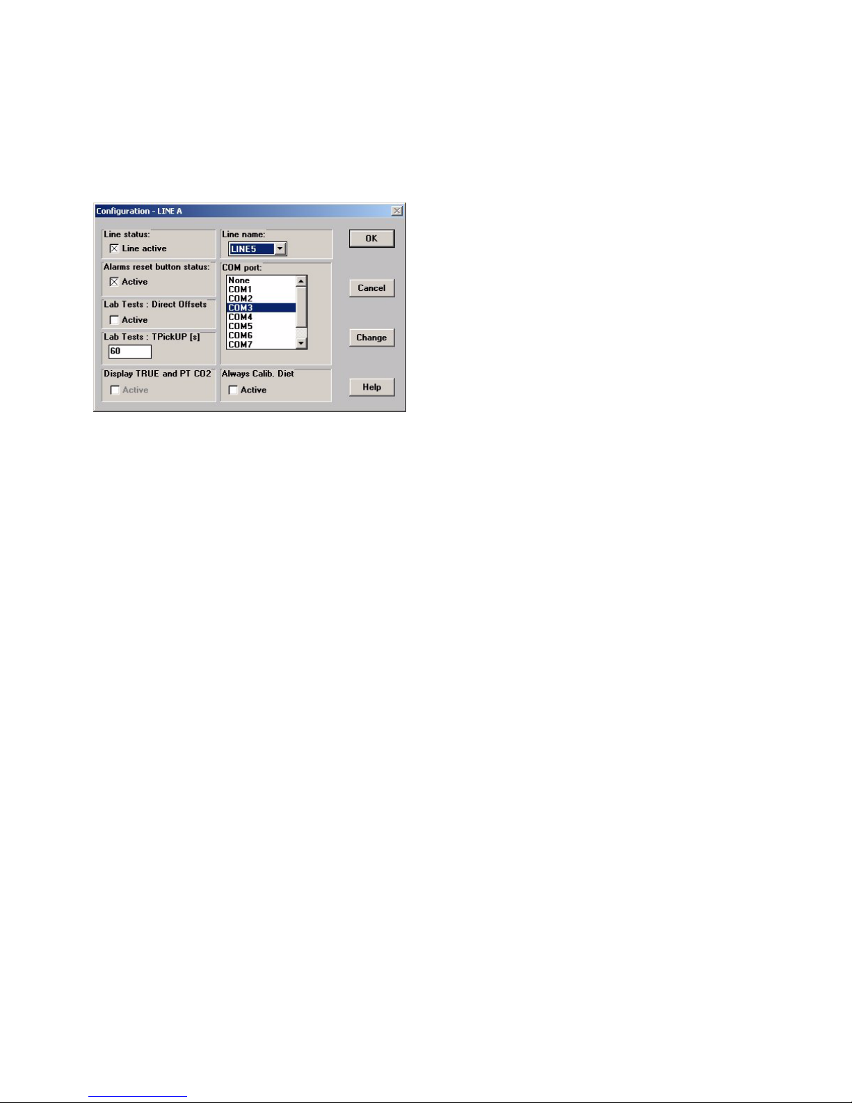
Setting a LINE Configuration
Up to two filling lines may be displayed in the
program window. Each line will be connected to a
separate PC COM port, which will have been set
up during the installation process.
Access the LINE you wish to configure, by
selecting the Line A or Line B option. Modify
parameters for that LINE by selecting the Change
button.
Products List
The Products List option allows you to set a
number of parameters for each product. There is
one product list per LINE, each with a maximum
of 9998 products. Note that product zero is
reserved for water measurement, and product
9999 is the default product used by the system
when the LINE is inactive. The default values for
both of these products are pre-set and cannot be
modified.
First select the LINE you wish to enter/modify
details for, by selecting either LINE A or LINE B in
the top left box.
Then select a product using one of the following
methods:
• By typing the product number, if known,
in the upper right-hand box
• By using the right-hand scroll bar
• By using the Search button to find a
product name
Once a product is selected, you can now enter/
modify the default parameters. Note that
modifications are only activated the next time a
run is started for this product.
Oxygen and Temperature Values
Set the units and limits for oxygen and
temperature displays and alarms. The values are
applicable to all products on both Line A and B.
Autosave
This option allows you to select the time delay for
automatically saving measurement data. Set to
None (no Autosave required), End of Run (save
only on completion) or at a time interval of 1, 2, 5,
10, 30 or 60 minutes.
As the year is not part of the filename, ensure
these measurement files (MMDDHHMM.cbo) are
backed up and deleted at the end of each year.
Water Calibration Status
For Diet measurements only, it may be desirable
to perform a water density calibration periodically.
This can be conveniently done during a long
rinse-down period. To enable this calibration,
select this option, and turn the status to On.
Alarms Delay
System alarms are disabled each time a new run
is started or when the Alarms ON/OFF button is
selected. The ProBrix Plus PC Program
automatically re-enables these after a delay
period of 5 minutes.
Selecting this option and entering a value of
between 0 and 30 will override the default to the
new value.
Sound Alarms
The ProBrix Plus PC Program can trigger audible
alarm messages. To receive these messages on
your PC, it must be equipped with speakers and
have a sound card installed.
Serial Output
You can send formatted measurement and
product data to other computers on your network.
Select the serial communications port linked to
the other computer. You cannot use the same
ports that have already been configured for LINE
A and/or LINE B.
For detailed information on the format of the data
elements transmitted, please press the Help
button on this window and then select Additional
serial output help.
PC Configuration Menu

Page 7
BAROMETRIC PRESSURE SENSOR
The instrument internal barometric pressure
sensor is calibrated at the factory, and normally
requires no further attention. However, you may
wish to calibrate it against your own
instrumentation, or simply check the instrument
for accuracy.
CO
2
SENSOR
The sensor can be calibrated using either:
1) A source of 100% pure CO
2
gas at a
known elevated pressure (Partial
Pressure)
2) A known concentration of CO
2
gas at a
known pressure (Fraction)
3) A known concentration of dissolved
CO
2
(Dissolved)
The Partial Pressure method is generally
recommended when measuring at higher line
pressures, and requires a precise in-line pressure
gauge to perform.
For the Partial Pressure and Fraction methods,
shut off the sample flow to the sampling module,
then open the front panel and remove the CO
2
sensor from its flow chamber. Do not disconnect
the cables or purge gas connections from the
sensor. Before calibrating, make sure that the grill
in the front of the CO
2
sensor is clean and dry.
Insert the sensor in the flow chamber, and tighten
with its collar.
The Dissolved method requires a known
concentration of CO
2
dissolved in liquid as a
reference sample, flowing in-line through the
sample line.
For all of the three methods described above,
expose the sensor to the gas and stabilize the
reading by operating in Measurement Mode for
about 30 minutes. After this time, press ESC and
select CALIBRATE from the main menu, followed
by SENSOR CO2 and the calibration method.
Then, select your calibration measurement unit.
Enter the gas concentration of the calibration
medium. Press ENTER to start the calibration
process. The instrument starts three calibration
cycles. The gas and temperature measurements
are displayed along with the current calibration
cycle number.
On completion of the three cycles, the instrument
then shows the sensitivity of the sensor as a
percentage of the sensitivity determined when
calibration was last performed.
This percentage must be between 50% and 150%
in order to calibrate. If the percentage is outside
the limits, you will see the CALIBRATION OUT
OF BOUNDS message. You will need to press
ESC to continue. Check that the membrane does
not need to be replaced and that no leaks are
evident.
If the percentage is within the limits press ENTER
to accept and complete the calibration process
(the message CALIBRATION COMPLETE will
appear briefly) or ESC to abort.
O
2
SENSOR
The In Air method places the O
2
sensor in water-
saturated air, to provide a known oxygen
reference against which to calibrate.
Shut off the pump and turn off the sample flow to
the sampling module. Open its front panel and
remove the O
2
sensor from its flow chamber. Do
not disconnect the sensor cable.
Dry the sensor thoroughly, before placing the
sensor storage cap under tap water. Shake off
any excess water, but leave a few drops inside
the cap. Then, loosely place the storage cap back
on the sensor, holding it in place by a few turns of
its collar.
Select CALIBRATE from the main menu followed
by O2 IN AIR to start the calibration. The process
is then similar to the CO
2
sensor calibration.
The Direct method calibrates the oxygen sensor
against a liquid sample containing a known level
of dissolved O
2
, flowing through the sample line.
Select CALIBRATE from the main menu followed
by O2 DIRECT and the calibration units. Then
enter the gas concentration of the calibration
sample to start the calibration. The process is
then similar to the CO
2
sensor calibration.
Calibration - From Instrument

Page 8
DIET CALIBRATION
There are three types of diet calibration available,
depending on the type of product.
Automatic (diet-a and T.A.-a products only)
Automatic calibration performs a calibration
based on three successive stable measurement
cycles at the start of a product run, and assumes
the product is in spec when the run starts. After
three successive stable measurements, the new
Diet Calibration Coefficient is calculated based on
the target value for the product.
If there is a large difference between the new
coefficient and the last calibration, a warning
message will be displayed when you press the
Product button, showing the percentage
difference between the two values.
Manual (diet-m and T.A.-m products only)
A dialog box appears automatically. The last five
measurements are initially set to zero.
Once the measurements displayed indicate a
stable condition (at least three successive stable
measurement cycles), press OK to close the
dialog box and to calculate the new slope value
for the current product, which is based on the
value in the edit box.
The target measurement for the product is
automatically displayed in the edit box, as the
calibration value. This can be changed based on
any Lab Tests performed, as it is used in
calculating the calibration coefficient.
Absolute (diet and T.A. products only)
Before doing a calibration, it is necessary to check
your water calibration coefficient first. This can be
done during the next rinse-down period.
Make sure you have set the Water Calibration
Status to On and select water (product number 0)
as the product for measuring. As you start the
measurement process, a new dialog box appears
automatically.
The dialog box will initially display zeros in the last
five measurements column. These values are
then updated every 15 seconds, as new as
measurements are taken.
When the measurements indicate a stable
condition, press OK to close the dialog box and
apply the most recent reading (n1) as the new
water coefficient. This new coefficient will be
applied as the water correction factor for all diet
and T.A. products.
Once the water calibration is complete, you can
now go through the product calibration process.
Select the Calibration button in the Products
List window for the required product. This will
display the density of the syrup (at 20°C) and the
mixing ratio (volume of syrup to volume of water),
which can only be modified if this is a diet product
(not applicable to T.A. products).
The current Slope value is displayed, along with
the Water calibration coefficient calculated during
the water calibration run described above. These
can be changed if required.
Press Calculate, to compute a new slope value
for the product. Press OK to apply these new
parameters to future measurements of this
product.
Calibration - From PC

Page 9
The following table lists possible measurement errors, which could be caused by poor handling of the
instrument and/or identifiable installation conditions.
Measurement Troubleshooting
Symptom Probable Cause Corrective Action Expected Result
Message Out Sensor not connected
Check sensor cable
connection (at sensor and
instrument end)
Measurement should return after
approximately 20 seconds
Message Prg
(CO
2
)
Purge pressure too low or
wrong purge gas
Restore correct purge pressure and gas (refer to the TC
Sensors - Maintenance &
Installation Manual for
details). Push the small plastic tube firmly into the purge
exit and check purge flow rate
(over 3 bubbles per second.)
Check voltage in continuous
purge mode.
In continuous purge mode,
voltage should be in the range
-2.5V to +4.5V. If purge flow rate
is too small, or if voltage remains
above 4.5V, contact your
Orbisphere agent
Damaged sensing
element caused by
mishandling during
membrane replacement
For experienced service
personnel only: Remove
membrane and support.
Check for broken wires of the
thermal conductivity chip
under microscope
Contact your Orbisphere agent
System does not
start: No display
or backlight
Improper line voltage Check instrument voltage
Select proper voltage (115V or
230V) on power supply card
Blown fuse
Unplug instrument and
replace blown fuse.
Instrument should start up. If not,
or if fuse blows again, contact
your Orbisphere agent
High sample
temperature
Blockage of sample flow
causing heat buildup from
pump
Check outlet of sample flow
for blockage. If a check valve
is in use, verify proper
orientation
Temperature should decrease as
normal sample flow resumes
Voltage drift
during
measurement
(CO
2
)
Purge gas pressure too
low
Set 2 bar gauge pressure or
adjust pressure in order to get
over 3 bubbles per second
from exit tube
Measurement will return to
expected value
Low reading
(CO
2
)
Leak in purge inlet line
Check line for leaks with
soapy water
Expected reading
High reading
(CO
2
)
Erroneous calibration in
gas with a wet membrane
protection grill
Recalibrate in liquid, or,
dry out the membrane and
calibrate in gas
Expected reading
Totally erratic
readings (CO
2
)
Water condensation into
the thermal conductivity
element due to purge
failure or humid purge gas
Blow dry purge gas in "contin-
uous purge mode" overnight.
Resume measurement mode.
In most cases, sensor operates
properly. But condensation may
result in serious damage,
requiring service

Page 10
Measurement Troubleshooting (cont)
Symptom Probable Cause Corrective Action Expected Result
Noisy reading
during gas
calibration
Calibrating gas flow
restricted generating
pressure pulses
Make sure calibration gas
flows freely
Stabilized reading
Noisy readings
during
measurement
Improperly mounted
protection cap or
membrane on CO
2
or O2
sensor
Turn off purge gas and check
membrane and protection
cap mounting procedure.
Restart purge
Stabilized reading
Leaking solenoid valve in
CO
2
sensor
Check purge outlet. No gas
bubble should evolve during
the measurement ramp
If solenoid leaks (more than 1
bubble in 15 seconds), return
sensor to Orbisphere
Grounding mismatch
between Orbisphere
instrument and electronic
accessories (plotter,
terminal)
Plug all accessories and
instrument into same mains
terminal
Stabilized reading
Calibration out of
bounds
Wrong membrane model;
pierced/torn membrane;
or two membranes
superimposed
Replace membrane
Calibration constant should be
±50% of default value
Wet protection cap
Blow grill with compressed air
and let dry, carefully, in dry
gas flow for one hour
Wrong calibration values
entered against actual
calibration fluid or
pressure
Check that gas concentration
or pressure fit the entered
numerical data and units

Page 11
The following table lists sensor warning messages, where #n is defined as follows:
• #0 refers to the CO
2
sensor
• #1 refers to the Brix/Diet sensor
• #2 refers to the O
2
sensor
The last three messages in the table apply to the Brix/Diet sensor only.
Sensor Warning Messages
Message on
Instrument LCD
LCD
Code
PC
Event
List
High/
Low
Relay
Hi-Hi/
Lo-Lo
Relay
Reason Action
#n CHECK
THE SENSOR
Out
Sensor
out
On On Sensor disconnected Connect sensor
#n WARNING
THERMAL
CUTOFF
Hot
Sensor
too hot
On On Sensor Thermal cutoff Check process
#0 SENSOR
PURGE
FAILURE
Prg Overflow On On
At the beginning of a
measurement cycle if
V3beg< -2500mV or
V3beg> +4450mV
Restore purge gas
#0 RAMP LIMIT
VIOLATED
Lmt Overflow On On
At the end of a
measurement cycle if
V3end< -2500mV or
V3end> +4450mV
Check membrane
#0 PURGE
VOLTAGE
DRIFTING
Chk N/A Off Off
At the beginning of a
measurement cycle if
V3beg< -2000mV or
V3beg> +3950mV OR
at the end of a measurement cycle if
V3end< -2000mV or
V3end> +3950mV
Check purge gas
#n ATTENTION
LOW LIMIT
LoL Low limit On Off Low limit alarm Check process
#n ATTENTION
HIGH LIMIT
HiL
High
Limit
On Off High limit alarm Check process
#n ATTENTION
LOWLOW LIMIT
LLL
Lo/Lo
limit
On On LowLow limit alarm Check process
#n ATTENTION
HIGHHIGH LIMIT
HHL
Hi/Hi
limit
On On HighHigh limit alarm Check process
OSCILLATOR
STOPPED
Osc Overflow On On
Brix/Diet sensor
malfunction
Check sensor
connections
U-TUBE EMPTY Emp Overflow On On
Brix/Diet sensor
U-tube empty
Restore sample
DEGASSING IN
U-TUBE
Deg Overflow On On
Sample drop-off in
U-tube
Restore sample

 Loading...