


Operator Quick Guide
ORBISPHERE 29981
Revision D - 16/09/2008
Page 2
About this Guide
The information in this guide has been carefully
checked and is believed to be accurate. However,
Hach Ultra assumes no responsibility for any
inaccuracies that may be contained in this guide.
In no event will Hach Ultra be liable for direct,
indirect, special, incidental, or consequential
damages resulting from any defect or omission in
this guide, even if advised of the possibility of
such damages. In the interest of continued
product development, Hach Ultra reserves the
right to make improvements in this guide and the
products it describes at any time, without notice or
obligation.
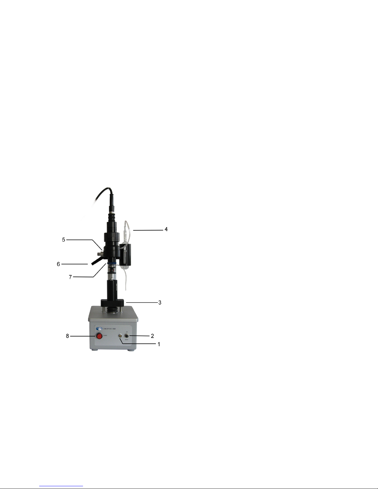
Sampler Description
The PharmaPack can analyze volumes as small
as one milliliter, in ampoules and vials. The
oxygen sensor makes headspace gas
measurements and sends them to the analyzer
for display. The package sampler is operator
controlled. Position of the sample platform
controls the flow of purge gas.
When the package moves up, the piercing needle
assembly is pressed up against the bottom of the
flow chamber, thus blocking purge gas flow by
compressing the inner O-ring. Note the difference
in the space and the compression of the O-rings
between the flow chamber and the needle
assembly.
Subsequently, when deaerated water is
dispensed into the package, the headspace gas is
forced up the inner needle, and into the flow
chamber.
The arm (5) supports the oxygen sensor, the flow
chamber, and the piercing needle assembly. A
black handle (6), located at the rear of this arm,
allows for height adjustment to fit the package
size.
The motorized sample holding platform (3) moves
up and down, controlled by the toggle switch (2)
on the front panel. When the toggle switch is
lifted, the platform stops automatically at a preset
level. This is set by the adjustable red lever (7),
located behind the piercing needle. When the
toggle switch is lowered, the platform stops
automatically at a factory preset level.
Two indicator lights are located on the front panel.
A red light (8) illuminates when the power is
turned on (switch on the back panel). The light (1),
at the side of the toggle switch, is orange as the
sample platform is raised, turns to green when the
platform is lowered, and is off when the platform
stops.
The oxygen sensor is mounted into the top of the
flow chamber and the piercing needle assembly is
attached to the bottom of the flow chamber.
A purge gas connection is located on the flow
chamber side. An outlet tube (4) is connected to a
small glass bubbler secured in a plastic holder,
and which allows a visual check of the purge gas
flow.
A deaerated water dispenser (not shown) is used
for forcing the headspace volume into the flow
chamber for measurement. This dispenser is
connected by flexible tubing to the piercing needle
assembly.
Operating Information

Page 3
Check Deaerated Water Dispenser
Check that sufficient deaerated water
is available in the dispenser before
starting a measurement session.
For better results, make sure there
are no air bubbles trapped in the tube
attached to the PharmaPack.
Check the amount of water to be
delivered with each shot is set
correctly (the recommended quantity
is 1mL).
If you purchased the model 28300 Orbisphere
dispenser with your PharmaPack, lift the plunger
to ensure it dispenses water correctly (no air
bubbles) and returns automatically to the closed
position. You may need to do this a few times until
the plunger returns smoothly to the start position.
Adjust Package Support Ampoule Height
To adjust the ampoule
package support to the height
of the ampoule, place an
ampoule inside the package
support, with the flat end of the
ampoule in the smaller (top)
part of the support. Screw
support together, finger-tight.
To adjust height, turn the Allen
screw on the bottom of the
package support (top picture)
until the flat end of the glass
ampoule is even with the top
surface of the support (bottom
picture).
Needle Assembly Check
Check the correct needle assembly is used. The
package sampler uses two different piercing
needles, one for ampoules and one for vials. If
you use both, you must use the correct piercing
needle assembly each time.
The piercing needle assembly for ampoules has a
black knurled collar, while the piercing needle
assembly for vials has a grey knurled collar.
Adjust the Arm Height
Lower the sample platform all the way and
remove the rubber seal from the piercing needle.
Place a package support on the sample platform.
• Ampoules: Leave the ampoule support
empty, with both parts screwed tightly
together.
• Vials: Place a sample vial into the
package support.
Loosen the black handle and adjust height of arm
until the needle is 2 cm above the top of the
ampoule package support (left photo) or the vial
septum (right photo). Then, tighten the handle.
Adjust Piercing Stop Height
When the toggle
switch is raised to the
up position, the
platform is lifted and
stops automatically
at a preset height.
This level is set by
the position of the red
lever, located behind the piercing needle.
Move the toggle switch to up.
• Ampoules: When the top of the cutting
edge of the needle is level with the top of
the empty package support, stop the
platform move by switching to off.
• Vials: When the needle start to pierce
the septum of the vial, stop the platform
move by switching to off.
Loosen the Allen screw on the side of the red
lever (located on vertical post behind needle, see
photo). Adjust the red lever until it just touches the
top of the package support.
Tighten the Allen screw and reinstall the needle
rubber seal.
If proper sealing cannot be achieved with the
adjustment above, replace the needle rubber
gasket. Lower the sample platform, remove and
install a new rubber gasket around the needle.
Preliminary Checks and Set Up

Page 4
Operating Sequence

Page 5
The needle
assembly for
vials has a grey
knurled collar,
while the needle
assembly for
ampoules has a
black collar.
The rubber gasket used for vials is a cylindrical
gasket (above left), while the H-shaped rubber
gasket is used for glass ampoules (above right).
Procedure for Glass Ampoules
Setup
1) Switch the analyzer into Measure mode
2) Start the flow of purge gas from a
cylinder of pure nitrogen. Check the
flow rate in the glass bubbler, and verify
that 2-3 bubbles appear each second.
3) Purge the flow chamber until the
analyzer reading is very low (<0.10%)
4) Check that no air is present in the water
tube or in the piercing needle assembly.
To do this, place a beaker under the
piercing needle assembly to collect
water from the needle. Then, from the
deaerated water dispenser, send 1 ml
(one shot) through the water tube and
piercing needle into the beaker
Measurement
Wet the inside of
the two-part
package support
and place the
sample ampoule
inside.
The flat end of the
ampoule must be
flush with the flat
end of the smaller
piece of the support. To insure proper placement,
put the support on a table and insert the ampoule
carefully. Screw the support together, finger-tight.
Scribe a 3 mm circle on the exposed flat end of
the ampoule with the diamond tip pencil provided.
If you do not do this, the mechanical shock of
piercing the ampoule could introduce sufficient air
to generate a false reading.
1) Place the package support on the
sample platform with the exposed end
of the ampoule up
2) Send 1 ml of deaerated water through
the piercing needle assembly, onto the
exposed end of the ampoule in the
package support. This water removes
any air trapped between the ampoule
surface and the sampling system
3) Move the toggle switch on the front of
the sampler base to the up position.
The indicator light turns orange
4) The sampling platform moves up and
stops automatically at the correct level
after piercing the ampoule. The purge
gas shuts off automatically just before
the needle pierces the ampoule (no gas
bubbles should appear from the purge
gas exit)
5) From the dispenser, send 1 ml of
deaerated water through the piercing
needle and into the ampoule. Watch for
bubbles at the purge gas exit tubing
6) Once the signal on the analyzer display
peaks, record the value. The signal will
increase at first, then stabilize. You
should record the value at the end of
the increase slope, right at the
beginning of stabilization
7) Move the toggle switch down. The
indicator light turns green. The
sampling platform is lowered and stops
automatically
8) Remove the package support and
unscrew the two parts
9) With a pencil, carefully push the
ampoule out of the support and rinse
and wipe the support with a paper
tissue
Procedure for Vials with Rubber Septum
The package supports for vials are one piece.
Place the vial, with septum up, into the package
support. There is no setup needed, just let the
needle pierce the rubber septum of the vial. The
measurement process is then the same as for
glass ampoules.
Sampling Procedure

Page 6
Using the Test Unit
The test unit (illustrated left)
allows for a variety of tests
without having to pierce
actual vials or ampoules.
A purge gas inlet is situated at
the bottom of the unit, with the
outlet at the top.
Check for Purge Gas Leaks
To test for purge gas leaks, place a beaker of
water on the sample platform. Then raise the
platform so that the needle is immersed in the
water (but the beaker is not pressing on the
needle or gasket).
Start the purge gas and regulate the purge gas
pressure to slightly more than atmospheric
pressure.
When the purge gas is on, bubbles should be
visible in the glass bubbler, and from the needle in
the beaker. However, when the purge gas is off,
the bubbling should stop.
The analyzer display should show a change of no
more than 0.01 kPa per minute, otherwise a leak
may be present and you should check all fittings.
Unable to Purge the System
If you observe no bubbles when the purge gas is
on during the preceding test, check to see if either
the piercing needle assembly is too tight or the
sensor is improperly mounted on the flow
chamber.
Sudden Jet of Water
A sudden jet of water can come out of the purge
gas exit tubing if the purge gas pressure is too
high. Excessive purge gas pressure can cause
gas to leak into the flow chamber during the
measuring phase, thus distorting readings. Adjust
purge gas pressure and flow rate.
Check for Air Leaks
If you suspect an air leak somewhere in the flow,
first make sure that your purge gas supply is
running, and that your sensor is at baseline, that
is, showing a typically low oxygen value.
Fill the test unit with deaerated water, full enough
to form a protruding meniscus at the test unit's
opening. Place the test unit on the sample
platform and raise the test unit. When the rubber
gasket forms a seal with the test unit, stop the
platform.
After five minutes, check the instrument
measurement. The oxygen value should remain
constant, rising no more than 0.05% (kPa) during
that delay. If the value increases significantly,
then you may assume that the system is leaking.
Check all appropriate fittings and try this test
again.
Alternate Check for Purge Gas Leaks
The display value could also decrease in the
preceding test if there is leakage of purge gas into
the flow chamber. First, verify the presence of
bubbles in the glass bubbler.
Then, place the test unit on the sample platform
and raise the platform until the rubber gasket
forms a seal with the test unit. Check to see that
the bubbling stops.
If the bubbling does not stop, the leak is
continuous. Disassemble the piercing needle
assembly, and replace the small O-ring. (Do not
forget to place a thin film of silicone grease
around the O-rings before reassembling the
piercing needle assembly.)
If the purge gas tubing "burps", the leak probably
is due to purge gas pressure that is too high.
Adjust purge gas pressure and flow rate.
Troubleshooting

Page 7
Check for Water Leaks
Connect a source of high purity N2 with a known
concentration of O
2
to a needle to pierce the test
units rubber septum. (Use N
2
with a concentration
of O
2
close to the concentration that you will want
to measure).
Insert the needle into the rubber septum, which is
located near the bottom of the test unit.
Place the test unit on the sample platform and
raise the platform until the rubber gasket forms a
seal with the test unit. Check if the instrument
measurement corresponds with the known
concentration of O
2
in the gas.
Then, remove the needle from the test unit and
check the measurement display. If the reading
decreases with the removal of the needle, water is
probably trapped in the flow chamber.
Purge the system with more N
2
and repeat the
reading. If the decreasing reading persists,
indicating that the flow chamber has not dried out,
remove the sensor from the flow chamber and
carefully dry the sensor face with a clean cloth.
Check Oxygen Values
Connect an oxygen supply to a regulator and a
needle to pierce the test unit's rubber septum.
Use a supply of known O
2
content, preferably of a
value that closely matches your expected sample
oxygen level, for example, 97% N
2
, 3% O2, to
match a 3% expected sample value. You also
may wish to install a three way valve ahead of the
regulator to allow for alternate gas sources.
Insert the needle into the rubber septum located
near the bottom of the test unit. Place the test unit
on the sample platform, and run enough gas to
purge the test unit cavity.
Then, raise the sample platform. As the test unit
approaches the rubber gasket, drop the flow of
gas to a trickle (0.01 to 0.03 bar) just before it
makes contact. After the rubber gasket forms a
seal with the test unit, the glass bubbler should
show a few bubbles per second. Check if the
analyzer measurement value matches the gas
sample.
Check for Clogged Needle
Fill a small
container with
soapy water and
place on top of the
test unit.
With the purge gas
running, place the
test unit (with the
container on top) on the sample platform.
Raise the test unit so that the needle is immersed
in the soapy water but ensuring that the container
does not come into contact with the needle
assembly. Check for bubbles at the needle (as
illustrated above). If bubbles show in the glass
bubbler but not from the needle in the container,
then the needle may be clogged.
Unable to Obtain Low Residual Value
If you have performed all the checks above and
there are no air or water leaks, and you are still
having problems in obtaining a low residual value,
your sensor may need servicing.
Check Purge Gas Shutoff for Vials
Vial have different piercing characteristics,
because of the septum shape and its material.
These differences may require adjustment to the
rubber gasket surrounding the piercing needle.
When a sample vial is raised by the platform, two
actions occur:
1) The vial is applied against the rubber
gasket that surrounds the needle. This
action pushes up the piercing needle
assembly against the flow chamber.
This stops the flow of purge gas to the
flow chamber by compressing the inner
O-ring. Purge gas flow is indicated by
bubbles flowing from the exit tubing into
a beaker of water. When the purge gas
stops, there are no more bubbles.
2) The needle starts piercing the rubber
septum of the vial.
For proper headspace gas measurements, the
purge gas must stop flowing before the needle
pierces the septum of the vial. You may need to
adjust the height of the rubber gasket (shorten or
lengthen it) to ensure that the purge gas flow
stops right before the septum is pierced.
Troubleshooting (cont)

 Loading...