

Page 1

DOC023.52.90202
RTC101 P-Module
Real-Time Control System for Phosphorus Removal
User manual
02/2013, edition 4A
© HACH-LANGE GmbH, 2010, 2011,2013 All rights reserved. Printed in Germany.
Page 2

Page 3

Table of Contents
Section 1 Specifications ........................................................................................................................ 5
Section 2 General Information............................................................................................................... 7
2.1 Safety information............................................................................................................................... 7
2.2 Areas of application ............................................................................................................................ 8
2.3 Functional principle............................................................................................................................. 8
2.4 Scope of delivery ................................................................................................................................ 9
2.5 Instrument overview.......................................................................................................................... 10
Section 3 Installation............................................................................................................................ 13
3.1 RTC101 P-Module connection.......................................................................................................... 13
3.2 Dosing pump connection .................................................................................................................. 13
3.3 PHOSPHAX sc analyzer connection ................................................................................................ 13
3.4 sc1000 controller connection ............................................................................................................ 14
3.5 Flow rate signal connection .............................................................................................................. 14
3.6 Connection to the automation unit on the plant side.........................................................................14
Section 4 Parameterization and operation ......................................................................................... 15
4.1 Open-loop control and closed-loop control programs....................................................................... 15
4.2 Program change ............................................................................................................................... 16
4.3 Parameterization on the sc1000....................................................................................................... 18
4.4 Select sensors .................................................................................................................................. 29
4.5 Explanations ..................................................................................................................................... 31
Section 5 Maintenance ......................................................................................................................... 37
5.1 Maintenance schedule...................................................................................................................... 37
Section 6 Troubleshooting................................................................................................................... 39
6.1 Error messages ................................................................................................................................ 39
6.2 Warnings........................................................................................................................................... 39
6.3 Wear parts ........................................................................................................................................ 39
Section 7 Replacement parts and accessories ................................................................................. 41
7.1 Spare parts ....................................................................................................................................... 41
Section 8 Contact information ............................................................................................................ 43
Section 9 Warranty and liability........................................................................................................... 45
Appendix A MODBUS address setting ............................................................................................... 47
3
Page 4

Table of Contents
4
Page 5

Section 1 Specifications
Subject to change without notice.
Industrial Personal Computer (IPC), (Embedded PC)
Processor
Flash memory 2 GB compact flash card
Internal working memory 256 MB DDR-RAM (not expandable)
Interface RJ 45 (Ethernet), 10/100 MBit/s
Diagnostic LEDs Power, LAN speed, LAN activity, TC status, flash access
Expansion slot Compact flash type II slot with ejection mechanism
Clock
Operating system Microsoft Windows
Control software TwinCAT PLC Runtime or TwinCAT NC PTP Runtime
System bus 16 Bit ISA (PC/104 standard)
Power supply Via system bus (through power supply module CX1100-0002)
Max. power loss 6 W (including the system interfaces CX1010-N0xx)
Analog input 4–20 mA for flow rate measurement
Internal resistance 80 Ohm × diode voltage 0.7 V
Signal current 0–20 mA
Pentium®1, MMX compatible, 500 MHz clock rate
Internal, battery-buffered clock for time and date (battery can be
replaced)
®2
CE or Microsoft Windows Embedded Standard
Common mode voltage (U
Measurement error (for entire measurement
range)
Electrical surge resistance 35 VDC
Electrical isolation 500 V
Analog output 4–20 mA for dosing pump
Number of outputs 1
Power supply
Signal current 0–20 mA
Working resistance < 500 Ω
Measurement error
Resolution 12 bit
Conversion time ~ 1.5 ms
Electrical isolation 500 V
) 35 V max.
CM
< ± 0.3 % (from measurement range end value)
24 V DC via power contacts
(alternatively 15 V DC with bus terminal KL9515)
± 0.5 LSB linearity error
± 0.5 LSB offset error
± 0.1, % (relative to the measuring range end value)
(K-bus/signal voltage)
eff
(K-bus/signal voltage)
eff
5
Page 6

Specifications
Digital outputs
1-channel: 1 × for dosing pump and 1 × alarm
2-channel: 2 × for dosing pump and 1 × alarm
Nominal load voltage 24 VDC (–15 % / +20 %)
Load type Ohmic, inductive, lamp load
Max. output current 0.5 A (short-circuit proof) per channel
Short-circuit current 0.7 to 1.7 A
Reverse polarity protection Yes
Electrical isolation 500 V
(K-bus/field voltage)
eff
Power contact current consumption 20 mA typ. (for typ. 30 mA 2-channel device)
Equipment properties
Dimensions (L × W × H)
350 mm × 120 mm × 96 mm
(13.78 in. × 4.72 in. × 3.78 in.)
Mass approx. 0.9 kg
Environmental conditions
Working temperature 0 to 50 °C (32 to 122 °F)
Storage temperature –25 to +85 °C (–13 to 185 °F)
Relative humidity 95 %, non-condensing
Miscellaneous
Pollution Degree
Protection Class
Installation Category
Maximum Altitude
2
1
II
2000 m (6.562 ft.)
Protection class IP20
Installation DIN rail EN 50022 35 × 15
1
Pentium is a registered trademark of the Intel Corporation.
2
Microsoft Windows is a brand name for operating systems of the Microsoft Corporation.
6
Page 7
Section 2 General Information
2.1 Safety information
Please read this entire manual before unpacking, setting up, or operating this equipment.
Pay attention to all danger and caution statements. Failure to do so could result in serious
injury to the operator or damage to the equipment.
To prevent damage to or impairment of the device's protection equipment, the device may
only be used or installed as described in this manual.
2.1.1 Use of hazard information
DANGER
Indicates a potentially or imminently hazardous situation that, if not avoided, can result in death or
serious injury.
WARNING
Indicates a potentially or imminently dangerous situation that, if it is not avoided, can lead to death
or to serious injuries.
CAUTION
Indicates a possible dangerous situation that can have minor or moderate injuries as the result.
Indicates a situation that, if it is not avoided, can lead to damage to the device. Information that
requires special emphasis.
Note: Information that supplements points in the main text.
2.1.2 Warning signs
Read all labels and tags attached to the instrument. Non-observance may result in
personal injury or damage to the equipment..
This symbol is a warning triangle. Follow all safety notes that follow this symbol to prevent possible injuries. If this
symbol is located on the device, it refers to information in the operating and/or safety notes of the user manual.
This symbol can be attached to a housing or a barrier in the product and shows that electric shock risk and/or the
risk of a death through electric shock exists.
Electrical equipment marked with this symbol may not be disposed of in European domestic or public disposal
systems after 12 August 2005. In conformity with local and national regulations, European electrical equipment
users must now return old or end-of life equipment to the manufacturer for disposal at no charge to the user.
Note: You obtain instructions on the correct disposal of all (marked and not marked) electrical products that were
supplied or manufactured by Hach-Lange at your relevant Hach-Lange sales office.
NOTICE
7
Page 8

General Information
2.2 Areas of application
The RTC101 P-Module is a universal open-loop control and closed-loop control unit in
waste water treatment plants for automatic precipitant metering for phosphate
precipitation.
Depending on the operating situation, the precipitant dosage can be based on measured
values in the influent or effluent or based on profiles. The system automatically selects the
best possible strategy. The user is able to make restrictions manually.
The use of an RTC Module does not release the operator from the duty of care to the system. No
guarantees as to the functionality or operational safety of the system.
In particular, the operator must make sure that instruments connected to the RTC
open/closed-loop controller are always fully functional.
To make sure these instruments supply correct, reliable measurement values, regular
maintenance work (for example, cleaning of the sensor and laboratory comparative
measurements) is essential! (Refer to the user manual for the relevant instrument.)
2.3 Functional principle
In the following, a distinction is made between the open-loop control and the
closed-loop control of the precipitant concentration.
NOTICE
For the open-loop control of the precipitant dosing, the measuring point for the
phosphate concentration is upstream of the precipitant dosing point.
For the closed-loop control of the precipitant dosing, the measuring point for the
phosphate concentration is downstream of the precipitant dosing point.
The measuring point for the flow rate is usually located in the influent of the waste water
treatment plant. At the measuring point, the actual flow rate (influent quantity and
recirculation - e.g. RAS, MLR, etc) is determined via further entries in the RTC module.
If the measured values for the flow rate quantity and/or phosphate concentration are
temporarily not available (e.g. due to a malfunction), the system automatically refers back
to saved profiles.
Connect the following input signals on the control unit in order to make optimum use of all
system functions:
• Flow rate, measurement signal 4–20 mA
• Fault indicator signal of the flow rate measurement (230 V AC or 24 V DC)
In the event that measured value failures are not signaled according to NAMUR 43, as
the values are below the 4
Note: If these signals are not available, the equipment operates with limited functionality.
• sc1000 controller with PO4P PHOSPHAX sc analyzer.
The measured value is adopted directly.
• Dosing pump for the precipitant
The dosing pump is continuously actuated via a 0–20 mA or 4–20 mA current loop
signal as well as via a changeover contact. If the dosing rate is below the minimum
precipitant flow rate of the pump, the system automatically switches to pulse/pause
mode.
mA threshold.
8
Page 9

2.4 Scope of delivery
Each RTC101 P-Module is supplied with:
• SUB-D connector (9 pin)
• Ferrite core, folding
• Manual
Check that the order is complete. If anything is missing or damaged, please contact the
manufacturer or distributor.
The combination of pre-assembled components supplied by the manufacturer does not represent
a standalone functional unit. In accordance with EU guidelines, this combination of pre-assembled
components is not supplied with a CE mark, and there is no EU declaration of conformity for the
combination.
However, the conformity of the combination of components with the guidelines can be proved
through technical measurements.
General Information
NOTICE
9
Page 10
General Information
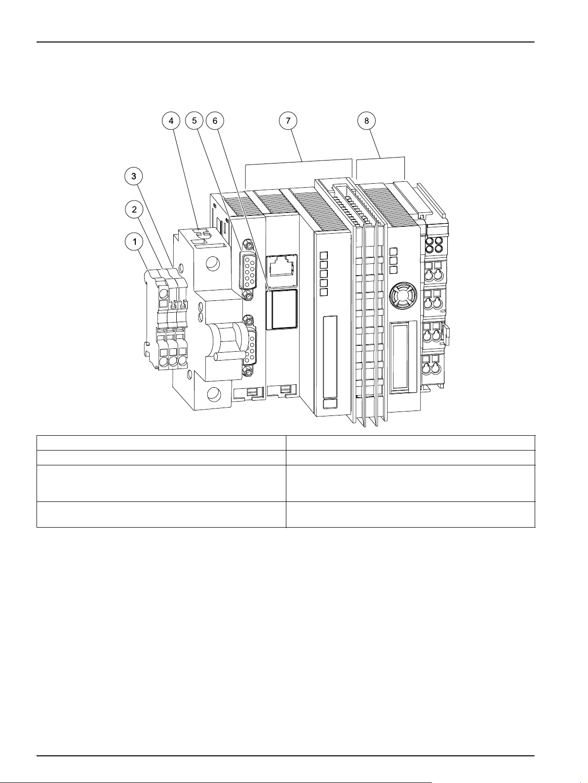
2.5 Instrument overview
Figure1 Base module RTC 24 V version .
1 PE (protective earth) 5 sc 1000 connection: RS485 (CX1010-N031)
2 24 V 6 Battery compartment
3 0 V 7 CPU base module, consisting of Ethernet port with
battery compartment (CX1010-N000), CPU module with
CF card (CX1010-0021) and passive aeration element.
4 Automatic circuit breaker (ON/OFF switch for item 7 and
8 without fuse function).
Note: All components are pre-wired.
8 Power supply module, consisting of bus coupler
(CX1100-0002) and terminal module 24V.
10
Page 11
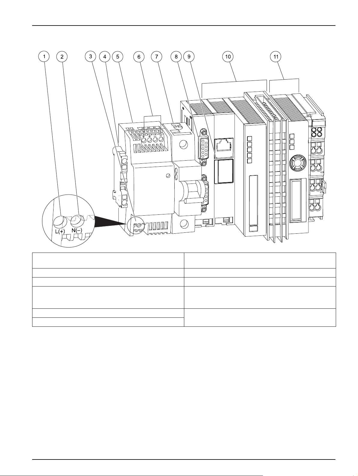
Abbildung 2 Base module RTC 100-240 V version
General Information
1 L(+) 7 Automatic circuit breaker (ON/OFF switch for item 10
and 11 without fuse function).
2 N(–) 8 sc 1000 connection: RS485 (CX1010-N041)
3 Input AC 100–240 V / Input DC 95 V–250 V 9 Battery compartment
4 PE (protective earth) 10 CPU base module, consisting of Ethernet port with
battery compartment (CX1010-N000), CPU module with
CF card (CX1010-0021) and passive aeration element.
5 24 V transformer (Specification Section 3.1.1, page 13) 11 Power supply module, consisting of bus coupler
6 Output DC 24 V, 0,75 A
(CX1100-0002) and terminal module 24V.
Note: All components are pre-wired.
11
Page 12

General Information
12
Page 13
Section 3 Installation
Only qualified experts may perform the tasks described in this section of the manual, while
adhering to all locally valid safety regulations.
Always lay cables and hoses so that they are straight and do not pose a tripping hazard.
Before the power supply is switched on, refer to the instructions in the relevant manuals!
3.1 RTC101 P-Module connection
The RTC module must be installed on a DIN rail/standard rail.
Install the module horizontally, with at least 30 mm clearance at the top and bottom, in
order to guarantee the functionality of the passive ventilation element. The RTC module is
operated solely via the sc1000 controller (see sc1000 controller operating instructions).
When used indoors, the RTC module can be installed in a control cabinet.
When used outdoors, the RTC module requires its own housing that follows the technical
specifications.
DANGER
CAUTION
CAUTION
3.1.1 Power supply to the RTC module
Alternating current may destroy the direct current system and therefore jeopardize user safety.
Never connect an alternating current voltage to the 24 V direct current model.
Table1 Supply voltage of the RTC Module
Voltage 24 V DC (–15 % / +20 %), max. 25 W
Recommended fuse C2
With 110–230 V option 110–230 VAC, 50-60 Hz, approximately 25 VA
Note: An external deactivation switch is recommended for all installations.
3.2 Dosing pump connection
There are two connections for the dosing pump:
• Current loop signal 0/4 to 20 mA for analog actuation of pumps with frequency
converters.
• 24 V output for the actuation of pumps without frequency converters or below the
analog adjustment range in pulse/pause mode.
Note: It must also be possible to switch the pump off via the digital output in the case of analog
actuation!
WARNING
3.3 PHOSPHAX sc analyzer connection
The measuring signal of the PHOSPHAX sc analyzer is transmitted to the RTC101
P-Module from the sc-system via the RTC communication card.
Previous designs of the analyzer (e.g. PHOSPHAX inter) can be connected to an analog
input card (YAB018).
13
Page 14

Installation
3.3.1 PHOSPHAX sc analyzer power supply
Refer to the PHOSPHAX sc manual.
3.4 sc1000 controller connection
Connect the SUB-D plug supplied to a dual-core, sheathed data cable (signal or bus
cable). For further information regarding the data cable connection, refer to the enclosed
assembly instructions.
3.5 Flow rate signal connection
If a flow rate measurement signal of 4 to 20 mA is available, connect it to the analog input
of the RTC module.
3.6 Connection to the automation unit on the plant side
Depending on the variant and option, the RTC101 P-Module is equipped with various
components that must be connected to the plant's automation unit.
• The volumetric flow rate is provided to the RTC module as a 0/4 to 20 mA signal for all
variants and options.
• The precipitant volume to be metered is delivered by the RTC module as a 0/4 to
20
mA signal for all variants and options.
Alternatively, the precipitant volume can also be output by the fieldbus variants
provided by the sc1000 (see sc1000 operating instructions).
• The RTC module supplies the digital output signal for activating the precipitant pump
at 0
V or 24 V.
• The RTC module supplies a collective fault message at 0 V (fault) or 24 V (device
functional).
Table 2 Signal allocation of individual components of the RTC module
RTC module options
Component Name Connection Signal Function 1-channel 2-channel
1
1
KL2032
KL2134
2-fold digital output
4-fold digital output
Single analog output KL4011 1(+) 3(-) +24 V/0 V Precipitant pump dosing rate X
2-fold analog output KL4012
1-fold analog input KL3011 1(+) – 2(-) 0/4 to 20 mA Feed volume flow Channel 1 X X
2-fold analog input KL3011 1(+) – 2(-) 0/4 to 20 mA Feed volume flow Channel 2 X
1
Ground to connections 3 and 7 or equal to voltage supply
1 +24 V/0 V Precipitant pump on/off X
5 +24 V/0 V No fault/fault X
1 +24 V/0 V Precipitant pump 1 on/off X
5 +24 V/0 V No fault/fault in channel 1 X
4 +24 V/0 V Precipitant pump 2 on/off X
8 +24 V/0 V No fault/fault in channel 2 X
1(+) 3(-) +24 V/0 V Precipitant pump 1 dosing rate X
5(+) 7(-) +24 V/0 V Precipitant pump 2 dosing rate X
14
Page 15

Section 4 Parameterization and operation
4.1 Open-loop control and closed-loop control programs
Four different programs are provided to enable optimal
adaptation to local conditions and to the available measurement
signals.
Programs 3 and 4 have various functions depending on whether
open-loop control or closed-loop control is selected.
4.1.1 Open-loop control
For the open-loop control of precipitant dosing, the measuring
point for phosphate concentration is upstream of the precipitant
dosing point.
4.1.1.1 Open-loop control according to phosphate concentration profiles
Program 1
Load-proportional open-loop control:
• Specified profile of the phosphate concentration in the reactor
inlet
• Specified profile for the flow rate
Program 2
Load-proportional open-loop control:
• Specified profile of the phosphate concentration in the reactor
inlet
• Flow rate measured value
Note: The prerequisite for this program is that the flow rate
measurement signal is valid. "Valid" means that the signal is present at
the relevant input.
4.1.1.2 Open-loop control according to measured phosphate values
Program 3
Load-proportional open-loop control:
• Measured value of the phosphate concentration in the reactor
inlet
• Specified profile for the flow rate
Note: The prerequisite for this program is that the PO4-P measurement
signal is valid. "Valid" means that the signal is present at the relevant
input.
Program 4
Load-proportional open-loop control:
• Measured value of the phosphate concentration in the reactor
inlet
• Flow rate measurement
Note: The prerequisite for this program is that both measurement signals
are valid. "Valid" means that the signal is present at the relevant input.
15
Page 16

Parameterization and operation
4.1.2 Closed-loop control according to measured phosphate values
For the closed-loop control of the precipitant dosing, the
measuring point for the phosphate concentration is downstream
of the precipitant dosing point.
Program 3
Closed-loop control:
• Measured value of the phosphate concentration in the reactor
outlet
• Specified profile for the flow rate (can be deactivated)
Note: The prerequisite for this program is that the PO4-P measurement
signal is valid. "Valid" means that the signal is present at the relevant
input.
Program 4
Load-proportional closed-loop control:
• Measured value of the phosphate concentration in the reactor
inlet
4.2 Program change
4.2.1 Automatic program change
• Flow rate measurement
Note: The prerequisite for this program is that both measurement signals
are valid. "Valid" means that the signal is present at the relevant input.
If a measurement signal drops out, an automatic program change
occurs and the system refers to the specified profile. The
program selection can be limited manually. The change between
programs occurs with a 5 minute delay, whereby the last
manipulated value set for the dosing is retained at the output.
16
Page 17

Figure 3 Program change
Q/PO4-P
Program 4
Q profile/PO
4
-P
Program 3
Q profile/PO
4
-P profile
Program 1
Q/PO
4
-P profile
Program 2
Parameterization and operation
4.2.2 Manual pre-selection
Pre-selection 1: Always Program 1
Pre-selection 2:
Pre-selection 3:
Open-loop
control:
Closed-loop
control:
Program 2 On signal drop out Program 1
Program 3 On signal drop out Program 2 if possible
Program 3 Otherwise program 1
4.2.3 CF card configuration
If both measurement signals become invalid at the same time,
the system switches between programs 4 and 1 without
intermediate stages.
Manual pre-selection limits the selection of programs.
NOTICE
Never remove the CF card from the RTC module during operation!
This can damage the instrument!
The function of the RTC101 P-Module, i.e. control/regulation, is
indicated on the CF card. If this setting is to be changed, please
contact the manufacturer's service department (Section 8).
17
Page 18

Parameterization and operation
4.3 Parameterization on the sc1000
4.3.1 User interfaces and navigation
Before the system is used, the user must be familiar with the sc
controller functions. Learn how to navigate through the menu and
perform the relevant functions.
4.3.2 System setup
1. Open the MAIN MENU.
2. Select RTC MODULE / PROGNOSYS and confirm.
3. Select the RTC MODULE menu and confirm.
4. Select the RTC module and confirm.
18
Page 19

4.3.3 1-channel open-loop control
1-channel open-loop control
CONFIGURE
Parameterization and operation
SELECT SENSOR
OPEN-LOOP
PRECIP. TYPE Precipitation, simultaneous precipitation, post-precipitation
SETPOINT PO4-P Desired orthophosphate value in effluent (refer to 4.5.1, page 31) [mg/L]
CORR FACTOR Percentage correction of precipitant dosing (see 4.5.2, page 31) [%]
BIO-P Phosphate biologically eliminated after influent (refer to 4.5.3, page 31) [%]
MIN DOS RATE Minimum flow rate of dosing pump [L/h]
PRESELECT PROG Programs 1 to 4 (refer to 4.1, page 15)
PROFILE Active when a measurement signal fails
Q-PROFILE
P-PROFILE Daily profiles for PO4-P concentrations, 2 h average (see 4.5.4, page 32) [mg/L]
WEEK PROFILE
IN- OUTPUTS
DOSING PUMP
MIN PUMP RANGE Lower threshold of flow rate range [L/h]
Select the sensor installed for the open-loop control (see Section 4.4, page 29).
Daily profiles (2 h average) of waste water influent according to feed measurement
signal
Percentage daily averages of the phosphate load (refer to 4.5.4, page 32)
(volume × concentration)
[m³/h]
[%]
MAX PUMP RANGE Upper threshold of flow rate range [L/h]
0/4...20MA Selection of transfer range according to pump input
CONTROL CYCLE Control cycle comprising on- and off-time (see 4.5.6, page 33) [s]
MIN RUNTIME Minimum on-time of pump (refer to 4.5.6, page 33) [s]
FLOW RATE
MIN Q-INFLUENT Minimum flow rate in inlet according to measurement signal [m³/h]
MAX Q-INFLUENT Maximum flow rate in inlet according to measurement signal [m³/h]
0/4...20MA Transfer range of 0/4–20 mA current loop, as set in the connected flow measuring instrument
MIN RET SLUDGE Minimum flow rate of return activated sludge pump(s) (refer to 4.5.7, page 34) [m³/h]
MAX RET SLUDGE Maximum flow rate of return activated sludge pump(s) (refer to 4.5.7, page 34) [m³/h]
Ratio between measured flow rate and return activated sludge volume, for a return
Q RET RATIO
Q INFL SMOOTH Smoothing of influent signal (refer to 4.5.7, page 34)
activated sludge volume proportional to the measured flow rate (refer to 4.5.7,
page 34)
[%]
19
Page 20

Parameterization and operation
1-channel open-loop control
CONFIGURE (CONTINUE)
PRECIPITANT
METAL CONTENT Metal concentration in precipitant (refer to 4.5.8, page 35) [g/L]
ATOMIC WEIGHT Relative atomic weight of active precipitant substance (refer to 4.5.8, page 35) [g/mol]
MODBUS
Start address of an RTC module within the MODBUS network. Default is 41. This
ADDRESS
DATA ORDER
DATALOG INTRVL Indicates the interval in which the data is saved in the log file [min]
MAINTENANCE
RTC DATA
RTC MEASUREMEN Displays up to 5 measured values; additional values can be selected by scrolling
RTC ACTUAT VAR Displays up to 5 actuating variables; additional variables can be selected by scrolling
setting must only be changed by the manufacturer's service department (Section 8).
(Refer to Appendix A, page 47)
Specifies the register order within a double word. Default is NORMAL. This setting
must only be changed by the manufacturer's service department (Refer to Section 8)
DIAG/TEST
EEPROM Hardware test
RTC COMM TO Communication time-out
RTC CRC Communication checksum
LOCATION
SOFTWARE VERSION Version number for service
RTC MODE Indicates the mode set in the RTC module.
A location name can be issued here for better identification of the RTC module e.g.
activation
2
4.3.4 2-channel open-loop control
In addition to the 1-channel version, a 2-channel version is also
available. The 2-channel version is able to control 2 phosphate
precipitants separately.
All of the key parameters appear twice and are identified as
channel 1 and channel 2.
In contrast to the 1-channel version, a percentage factor for
distribution of the profile (
measurement signals drop out, the percentage factor
PROFILE
distributes the influent waste water to the precipitant.
DIST PROFILE) has been added. If
DIST
20
Page 21

Parameterization and operation
2-channel open-loop control
CONFIGURE
SELECT SENSOR Select the sensors installed for the open-loop control (see Section 4.4, page 29).
OPEN-LOOP
PRECIP. TYPE Precipitation, simultaneous precipitation, post-precipitation
CHANNEL 1
SETPOINT PO4-P Desired orthophosphate value in effluent (refer to 4.5.1, page 31) [mg/L]
CORR FACTOR Percentage correction of precipitant dosing (see 4.5.2, page 31) [%]
BIO-P Phosphate biologically eliminated after influent (refer to 4.5.3, page 31) [%]
MIN DOS RATE Minimum flow rate of dosing pump [L/h]
PRESELECT PROG Programs 1 to 4 (refer to 4.1, page 15)
CHANNEL 2
SETPOINT PO4-P Desired orthophosphate value in effluent (refer to 4.5.1, page 31) [mg/L]
CORR FACTOR Percentage correction of precipitant dosing (see 4.5.2, page 31) [%]
BIO-P Phosphate biologically eliminated after influent (refer to 4.5.3, page 31) [%]
MIN DOS RATE Minimum flow rate of dosing pump [L/h]
PRESELECT PROG Programs 1 to 4 (refer to 4.1, page 15)
PROFILE Active when a measurement signal fails
Q-PROFILE
DIST PROFILE Percentage distribution of flow rate; input refers to channel 1. [%]
P-PROFILE Daily profiles of PO
WEEK PROFILE Percentage daily averages of the phosphate load (refer to4.5.4, page 32) [%]
IN- OUTPUTS
DOSING PUMP
CHANNEL 1
MIN PUMP RANGE Lower threshold of flow rate range [L/h]
MAX PUMP RANGE Upper threshold of flow rate range [L/h]
0/4...20MA Selection of transfer range according to pump input
CONTROL CYCLE Control cycle comprising on- and off-time (see 4.5.6, page 33)[s]
MIN RUNTIME Minimum on-time of pump (refer to 4.5.6, page 33) [s]
Daily profiles (2 h average) of waste water influent according to feed measurement
signal
-P concentrations, 2 h average (see 4.5.4, page 32) [mg/L]
4
[m³/h]
21
Page 22

Parameterization and operation
2-channel open-loop control
CONFIGURE (CONTINUE)
CHANNEL 2
MIN PUMP RANGE Lower threshold of flow rate range [L/h]
MAX PUMP RANGE Upper threshold of flow rate range [L/h]
0/4...20MA Selection of transfer range according to pump input
CONTROL CYCLE Control cycle comprising on- and off-time (see 4.5.6, page 33)[s]
MIN RUNTIME Minimum on-time of pump (refer to 4.5.6, page 33) [s]
FLOW RATE
CHANNEL 1
MIN Q-INFLUENT Minimum flow rate in inlet according to measurement signal [m³/h]
MAX Q-INFLUENT Maximum flow rate in inlet according to measurement signal [m³/h]
0/4...20MA
MIN RET SLUDGE Minimum flow rate of return activated sludge pump(s) (refer to 4.5.7, page 34) [m³/h]
Transfer range of 0/4–20 mA current loop, as set in the connected flow measuring
instrument.
MAX RET SLUDGE Maximum flow rate of return activated sludge pump(s) (refer to 4.5.7, page 34) [m³/h]
Ratio between measured flow rate and return activated sludge volume, for a return
Q RET RATIO
Q INFL SMOOTH Smoothing of influent signal (refer to 4.5.7, page 34)
CHANNEL 2
MIN Q-INFLUENT Minimum flow rate in inlet according to measurement signal [m³/h]
MAX Q-INFLUENT Maximum flow rate in inlet according to measurement signal [m³/h]
0/4...20MA
MIN RET SLUDGE Minimum flow rate of return activated sludge pump(s) (refer to 4.5.7, page 34) [m³/h]
MAX RET SLUDGE Maximum flow rate of return activated sludge pump(s) (refer to 4.5.7, page 34) [m³/h]
Q RET RATIO
Q INFL SMOOTH Smoothing of influent signal (refer to 4.5.7, page 34)
activated sludge volume proportional to the measured flow rate (Refer to 4.5.7,
page 34)
Transfer range of 0/4–20 mA current loop, as set in the connected flow measuring
instrument.
Ratio between measured flow rate and return activated sludge volume, for a return
activated sludge volume proportional to the measured flow rate (Refer to 4.5.7,
page 34)
[%]
[%]
22
Page 23

Parameterization and operation
2-channel open-loop control
CONFIGURE (CONTINUE)
PRECIPITANT
CHANNEL 1
METAL CONTENT Metal concentration in precipitant (refer to 4.5.8, page 35) [g/L]
ATOMIC WEIGHT Relative atomic weight of active precipitant substance (refer to 4.5.8, page 35) [g/mol]
CHANNEL 2
METAL CONTENT Metal concentration in precipitant (refer to 4.5.8, page 35) [g/L]
ATOMIC WEIGHT Relative atomic weight of active precipitant substance (refer to 4.5.8, page 35) [g/mol]
MODBUS
Start address of an RTC module within the MODBUS network. Default is 41. This
ADDRESS
DATA ORDER
DATALOG INTRVL Indicates the interval in which the data is saved in the log file. [min]
setting must only be changed by the manufacturer's service department (Section 8).
(Refer to Appendix A, page 47)
Specifies the register order within a double word. Default is NORMAL. This setting
must only be changed by the manufacturer's service department (Refer to
Section 8)
MAINTENANCE
RTC DATA
RTC MEASUREMEN Displays up to 5 measured values; additional values can be selected by scrolling.
RTC ACTUAT VAR
DIAG/TEST
EEPROM Hardware test
RTC COMM TO Communication time-out
RTC CRC Communication checksum
LOCATION
SOFTWARE VERSION Version number for service
RTC MODE Indicates the mode set in the RTC module.
Displays up to 5 actuating variables; additional variables can be selected by
scrolling.
A location name can be assigned here for better identification of the RTC module,
e.g. activation 2.
23
Page 24

Parameterization and operation
4.3.5 1-channel closed-loop control
1-channel closed-loop control
CONFIGURE
SELECT SENSOR
CLOSED-LOOP
SETPOINT PO4-P Desired orthophosphate value in effluent (refer to 4.5.1, page 31) [mg/L]
GAIN P CONTR. Proportional gain of the closed-loop control (refer to 4.5.5, page 32)
INTEGRALTIME Integral time of closed-loop control (refer to 4.5.5, page 32) [min]
DERIVATIVE TIME Derivative time of closed-loop control (refer to 4.5.5, page 32) [min]
MIN DOS RATE Minimum flow rate of dosing pump [L/h]
PRESELECT PROG Programs 1 to 4 (refer to 4.1, page 15)
PROFILE Active when a measurement signal fails
Q-PROFILE
P-PROFILE Daily profiles of PO4-P concentrations, 2 h average (see 4.5.4, page 32) [mg/L]
WEEK PROFILE Percentage daily averages of the phosphate load (refer to 4.5.4, page 32) [%]
IN- OUTPUTS
DOSING PUMP
MIN PUMP RANGE Lower threshold of flow rate range [L/h]
Select the sensor installed for the closed-loop control (refer to Section 4.4, page 29).
Daily profiles (2 h average) of waste water influent according to feed measurement
signal
[m³/h]
MAX PUMP RANGE Upper threshold of flow rate range [L/h]
0/4...20MA Selection of transfer range according to pump input
CONTROL CYCLE Control cycle comprising on- and off-time (see 4.5.6, page 33) [s]
MIN RUNTIME Minimum on-time of pump (refer to 4.5.6, page 33) [s]
FLOW RATE
MIN Q-INFLUENT Minimum flow rate in inlet according to measurement signal [m³/h]
MAX Q-INFLUENT Maximum flow rate in inlet according to measurement signal [m³/h]
0/4...20MA Transfer range of 0/4–20 mA current loop, as set in the connected flow measuring instrument.
MIN RET SLUDGE Minimum flow rate of return activated sludge pump(s) (refer to 4.5.7, page 34) [m³/h]
MAX RET SLUDGE Maximum flow rate of return activated sludge pump(s) (refer to 4.5.7, page 34) [m³/h]
Ratio between measured flow rate and return activated sludge volume, for a return
Q RET RATIO
Q INFL SMOOTH Smoothing of influent signal (refer to 4.5.7, page 34)
activated sludge volume proportional to the measured flow rate (Refer to
page 34)
4.5.7,
[%]
24
Page 25

Parameterization and operation
1-channel closed-loop control
CONFIGURE (CONTINUE)
PRECIPITANT
METAL CONTENT Metal concentration in precipitant (refer to 4.5.8, page 35) [g/L]
ATOMIC WEIGHT Relative atomic weight of active precipitant substance (refer to 4.5.8, page 35) [g/mol]
MODBUS
Start address of an RTC module within the MODBUS network. Default is 41. This
ADDRESS
DATA ORDER
DATALOG INTRVL Indicates the interval in which the data is saved in the log file. [min]
MAINTENANCE
RTC DATA
RTC MEASUREMEN Displays up to 5 measured values; additional values can be selected by scrolling.
RTC ACTUAT VAR Displays up to 5 actuating variables; additional variables can be selected by scrolling.
setting must only be changed by the manufacturer's service department (Section 8).
(Refer to Appendix A, page 47)
Specifies the register order within a double word. Default is NORMAL. This setting
must only be changed by the manufacturer's service department (Refer to Section 8)
DIAG/TEST
EEPROM Hardware test
RTC COMM TO Communication time-out
RTC CRC Communication checksum
LOCATION
SOFTWARE VERSION Version number for service
RTC MODE Indicates the mode set in the RTC module.
A location name can be issued here for better identification of the RTC module, e.g.
activation
2.
4.3.6 2-channel closed-loop control
In addition to the 1-channel version, a 2-channel version is also
available, which enables separate closed-loop control of two
phosphate precipitants.
All of the key parameters appear twice and are identified as
channel 1 and channel 2.
In contrast to the 1-channel version, a percentage factor for
distribution of the profile (
measurement signals drop out, the percentage factor
PROFILE
distributes the influent waste water to the precipitant.
DIST PROFILE) has been added. If
DIST
25
Page 26

Parameterization and operation
2-channel closed-loop control
CONFIGURE
SELECT SENSOR Select the sensors installed for the closed-loop control (see Section 4.4, page 29).
CLOSED-LOOP
CHANNEL 1
SETPOINT PO4-P Desired orthophosphate value in effluent (refer to 4.5.1, page 31) [mg/L]
GAIN P CONTR. Proportional gain of the closed-loop control (refer to 4.5.5, page 32)
INTEGRALTIME Integral time of closed-loop control (refer to 4.5.5, page 32)[min]
DERIVATIVE TIME Derivative time of closed-loop control (refer to 4.5.5, page 32)[min]
MIN DOS RATE Minimum flow rate of dosing pump [L/h]
PRESELECT PROG Programs 1 to 4 (refer to 4.1, page 15)
CHANNEL 2
SETPOINT PO4-P Desired orthophosphate value in effluent (refer to 4.5.1, page 31) [mg/L]
GAIN P CONTR. Proportional gain of the closed-loop control (refer to 4.5.5, page 32)[%]
INTEGRALTIME Integral time of closed-loop control (refer to 4.5.5, page 32)[%]
DERIVATIVE TIME Derivative time of closed-loop control (refer to 4.5.5, page 32)
MIN DOS RATE Minimum flow rate of dosing pump [L/h]
PRESELECT PROG Programs 1 to 4 (refer to 4.1, page 15)
PROFILE Active when a measurement signal fails
Q-PROFILE
DIST PROFILE Percentage distribution of flow rate; input refers to channel 1. [%]
P-PROFILE Daily profiles of PO
WEEK PROFILE Percentage daily averages of the phosphate load (refer to4.5.4, page 32) [%]
Daily profiles (2 h average) of waste water influent according to feed measurement
signal
-P concentrations, 2 h average (see 4.5.4, page 32) [mg/L]
4
[m³/h]
26
Page 27

Parameterization and operation
2-channel closed-loop control
CONFIGURE (CONTINUE)
IN- OUTPUTS
DOSING PUMP
CHANNEL 1
MIN PUMP RANGE Lower threshold of flow rate range [L/h]
MAX PUMP RANGE Upper threshold of flow rate range [L/h]
0/4...20MA Selection of transfer range according to pump input
CONTROL CYCLE Control cycle comprising on- and off-time (see 4.5.6, page 33)[s]
MIN RUNTIME Minimum on-time of pump (refer to 4.5.6, page 33) [s]
CHANNEL 2
MIN PUMP RANGE Lower threshold of flow rate range [L/h]
MAX PUMP RANGE Upper threshold of flow rate range [L/h]
0/4...20MA Selection of transfer range according to pump input
CONTROL CYCLE Control cycle comprising on- and off-time (see 4.5.6, page 33)[s]
MIN RUNTIME Minimum on-time of pump (refer to 4.5.6, page 33) [s]
FLOW RATE
CHANNEL 1
MIN Q-INFLUENT Minimum flow rate in inlet according to measurement signal [m³/h]
MAX Q-INFLUENT Maximum flow rate in inlet according to measurement signal [m³/h]
0/4...20MA Transfer range of 0/4–20 mA current loop, as set in the connected flow measuring instrument
MIN RET SLUDGE Minimum flow rate of return activated sludge pump(s) (refer to 4.5.7, page 34) [m³/h]
MAX RET SLUDGE Maximum flow rate of return activated sludge pump(s) (refer to 4.5.7, page 34) [m³/h]
Ratio between measured flow rate and return activated sludge volume, for a return
Q RET RATIO
Q INFL SMOOTH Smoothing of influent signal (refer to 4.5.7, page 34)
CHANNEL 2
MIN Q-INFLUENT Minimum flow rate in inlet according to measurement signal [m³/h]
MAX Q-INFLUENT Maximum flow rate in inlet according to measurement signal [m³/h]
0/4...20MA
activated sludge volume proportional to the measured flow rate (Refer to 4.5.7,
page 34)
Transfer range of 0/4–20 mA current loop, as set in the connected flow measuring
instrument.
[%]
MIN RET SLUDGE Minimum flow rate of return activated sludge pump(s) (refer to 4.5.7, page 34) [m³/h]
MAX RET SLUDGE Maximum flow rate of return activated sludge pump(s) (refer to 4.5.7, page 34) [m³/h]
Ratio between measured flow rate and return activated sludge volume, for a return
Q RET RATIO
Q INFL SMOOTH Smoothing of influent signal (refer to 4.5.7, page 34)
activated sludge volume proportional to the measured flow rate (Refer to 4.5.7,
page 34)
[%]
27
Page 28

Parameterization and operation
2-channel closed-loop control
CONFIGURE (CONTINUE)
PRECIPITANT
CHANNEL 1
METAL CONTENT Metal concentration in precipitant (refer to 4.5.8, page 35) [g/L]
ATOMIC WEIGHT Relative atomic weight of active precipitant substance (refer to 4.5.8, page 35) [g/mol]
CHANNEL 2
METAL CONTENT Metal concentration in precipitant (refer to 4.5.8, page 35) [g/L]
ATOMIC WEIGHT Relative atomic weight of active precipitant substance (refer to 4.5.8, page 35) [g/mol]
MODBUS
Start address of an RTC module within the MODBUS network. Default is 41. This
ADDRESS
DATA ORDER
DATALOG INTRVL Indicates the interval in which the data is saved in the log file. [min]
setting must only be changed by the manufacturer's service department (Section 8).
(Refer to Appendix A, page 47)
Specifies the register order within a double word. Default is NORMAL. This setting
must only be changed by the manufacturer's service department (Refer to
Section 8)
MAINTENANCE
RTC DATA
RTC MEASUREMEN Displays up to 5 measured values; additional values can be selected by scrolling.
RTC ACTUAT VAR Displays up to 5 actuating variables; additional variables can be selected by scrolling.
DIAG/TEST
EEPROM Hardware test
RTC COMM TO Communication time-out
RTC CRC Communication checksum
LOCATION
SOFTWARE VERSION Version number for service
RTC MODE Indicates the mode set in the RTC module.
A location name can be assigned here for better identification of RTC module, e.g.
activation 2.
28
Page 29

4.4 Select sensors
Figure 4 Select sensor
Parameterization and operation
1. To select the sensors and their sequence for the RTC
module, press RTC > CONFIGURE > SELECT SENSOR.
1ENTER — Saves the setting and returns to the
CONFIGURE menu.
2 CANCEL — Returns to the CONFIGURE menu without
saving.
3ADD — Adds a new sensor to the selection.
2. Press ADD (Figure 4, item 3).
A selection list of all subscribers to the sc1000 network
opens.
3. Press the required sensor for the RTC module and confirm
by pressing
Sensors in black type are available for the RTC module.
Sensors in red type are not available for the RTC module.
Note: PROGNOSYS is available for sensors marked (p) if these
sensors have been selected in conjunction with an RTC module
(refer to the PROGNOSYS user manual).
4 DELETE — Removes a sensor from the selection.
5UP/DOWN — Moves the sensors up or down.
ENTER below the selection list.
29
Page 30

Parameterization and operation
4. The selected sensor is shown in the sensor list.
Press ADD (Figure 4, item 3) to open the selection list again.
5. Select the second sensor for the RTC module and confirm
by pressing
Note: Previously selected sensors are shown in gray.
The selected sensors are shown in the sensor list.
ENTER below the selection list.
6. To sort the sensors in the order specified for the RTC
module, press the sensor and use the arrow keys to move it
(
Figure 4, item 5).
Press DELETE (Figure 4, item 4) to remove an incorrect
sensor from the sensor list again.
7. Press ENTER (Figure 4, item 1) to confirm the list once it is
finished.
30
Page 31

4.5 Explanations
4.5.1 Ortho-phosphate and total phosphate
The goal of phosphate control is to reduce the total phosphate in
the effluent stream at a waste water treatment plant. However,
the precipitation only affects the ortho-phosphate content. The
PO
-P target value specifies the ortho-phosphate value to be
4
maintained in the precipitation reactor. Therefore, this value must
be lower than the value to be maintained in the effluent.
Note: If CLOSED-LOOP is set in the controller, the setpoint is effective
immediately. If
effluent concentration of the reactor is required.
4.5.2 Recycling the chemical sludge
Precipitant savings can be achieved, particularly in activated
sludge plants, if existing chemical sludge is reused for
phosphorus elimination. In the case of precipitant overdosage,
the stoichiometrically excessive metal content (for metal
phosphate formation) is reused in the formation of metal
phosphate upon renewed contact with dissolved phosphate.
Renewed adsorption of phosphate, by precipitates already
formed, is possible. The existing precipitant·sludge portion thus
represents a reserve for the precipitation of P-influent peaks or
for a short-term failure of the dosing devices; however, other
authors consider this reserve to be minimal.
Parameterization and operation
OPEN-LOOP is set in the controller, the desired PO
-P
4
The precipitant savings automatically take effect for closed-loop
controls. To be able to use the reserve for open-loop controls
as well, the correction (
input reduces the precipitant dosing:
In the event of negative influences on the phosphate
precipitation, a positive correction value can be entered:
4.5.3 Biological phosphate elimination
The BIO-P parameter is used to take biological phosphate
elimination into account. If no phosphate elimination is effective at
the phosphate measuring point, the
specify the percentage of influent phosphates that is biologically
incorporated into the sludge on an empirical basis. In this case, it
is important to differentiate between the measurement of
ortho-phosphate and total phosphate. For total phosphate, the
"unavoidable" biological phosphate elimination must always be
taken into account. This can be set at 1 % of the BOD
increased biological phosphate elimination can be added in all
cases and must be estimated on the basis of empirical values.
CORR FACTOR)) can be used. A negative
Example:
A correction value of –50 % is set.
This reduces the precipitant dosing by half.
Example:
A correction value of +100 % is set.
This doubles the precipitant dosing.
BIO-P factor can be used to
. An
5
31
Page 32

Parameterization and operation
4.5.4 Phosphate profile
The same conditions as specified under 4.5.3, page 31 must
apply for the phosphate flow rate profile. If biological phosphate
elimination is still not effective at the measuring point, the flow
profile rate remains unaffected by the biological phosphate
elimination. If biological phosphate elimination is already effective
at the measuring point, this must also be reflected in the profile.
Note: In this case, the value zero (0) must be entered as Bio P
proportion!
For open-loop controls, the results of the online measurement
can be directly employed in the profile determination. This also
ensures that the measurement conditions are identical.
Due to missing data, the configuration for closed-loop controls
is more complex. A reliable data pool for a waste water treatment
plant can only be obtained on the basis of 2 h composite
samples. Any samples that were taken during unusual influent
events (heavy rains, unauthorized discharge) are excluded.
A sample unaffected by precipitation can only be taken from the
influent to the activated sludge plant. At this point, the organic
phosphorous has not yet hydrolyzed. If total phosphate is
determined here, the "unavoidable" biological phosphate
elimination must be considered.
Since the entry of a Bio-P amount is not possible for closed-loop
controls (option hidden), lower values can be entered directly. If
the online measurement fails, it is safer to forego a reduction.
Over the course of a week, there can be strong fluctuations in the
load on the waste water treatment plant. To ensure an accurate
representation of actual conditions, the daily profiles can be
superimposed with a weekly profile.
4.5.5 PID closed-loop (proportional, integral, differential closed-loop)
The proportional precipitant dosing quantity calculated by the
RTC module is increased or reduced by the proportional
intensification factor (
As the precipitant has already become effective at the measuring
point, the measurement indicates the following:
• The dosage is too low
• The dosage is sufficient
• The dosage is too high and must be corrected
accordingly
The proportional gain factor specifies the precipitant dosage
required based on the exceedance of the target value. Large
gains result in large changes to the dosing and therefore a high
closed-loop control speed; however, the closed-loop control
oscillations also increase in line with the gain.
GAIN P CONTR.) of the closed loop control.
32
The
DERIVATIVE TIME allows the RTC module to react not only
to the absolute target value deviations but also to the speed with
which the phosphate content rises or falls. Necessary corrections
can thus be made at an earlier stage.
Page 33

Parameterization and operation
Example:
A derivative time of 1 minute means that closed-loop control
takes place according to the phosphate concentration that is
actually achieved in only 1
value change remains the same).
The integration time takes effect by means of the temporal
integration of the control deviation (PO
actual value), to the actuating variable with the weighting by the
INTEGRALTIME. The integral time states when the integral
proportion has the same effect as the P proportion. A short
timeframe can lead to an overshoot or strong oscillations of the
PO
-P concentration. An increase in the integral time reduces the
4
oscillation. In this case, the I proportion of the closed-loop control
can be specified through the entry of
minute (if the current measured
-P setpoint to PO4-P
4
INTEGRAL TIME = 0.
4.5.6 Pump runtime
Setting tips: As a
DERIVATIVE TIME >0 min has a highly
significant impact on the metered precipitant quantity, this should
be used only in exceptional cases, e.g. plants demonstrating
rapid escalations in PO
-P concentrations.
4
To ensure the metered precipitant quantity increases/decreases
more quickly, the
INTEGRALTIME reduced. To ensure the metered quantity
changes more slowly, the
INTEGRAL TIME increased.
GAIN P CONTR. must be increased or the
GAIN P CONTR. must be reduced or the
The on/off duration in pulse/pause mode can be influenced via
the control cycle time (
CONTROL CYCLE). For example, with a
cycle time of 100 seconds and a dosing control value of 60 %, the
dosing pump is periodically switched on for 60 seconds and off
for 40 seconds. Short cycle times increase the switch frequency,
but enable more precise adaptation to individual requirements.
A minimum on-time is also configured to protect the dosing pump.
The pump is not activated for less than this time span. The time
must be a fraction of the control cycle time.
33
Page 34

Parameterization and operation
4.5.7 Inclusion of return sludge quantity
To be able to record the entire flow at the measuring point, the
return sludge quantity must also be taken into account,
depending on the specific application. For this purpose, the
minimum and maximum flow rate of the return activated sludge
pump(s) can be specified, as well as the ratio of return activated
sludge transport relative to the measured flow rate.
The flow rate, e.g. for simultaneous precipitation with a
measuring point in the activated sludge tank, is calculated as
follows:
Q RS
which the calculated return activated sludge volume is varied
according to Q RS
If the measuring location is at a measuring point that is not
influenced by the return activated sludge volume, all variables
described below must be set to "
Q
= Qto + QRSL
total
Where: QRLS = QRS
ratio
Within the limits of Q RS
minimum
and Q RS
ratio
maximum
.
× Qto
minimum
and Q RS
maximum
thus represent the limits within
0".
Under
MIN RET SLUDGE, the minimum flow rate of the return
sludge pump(s) must be specified in m³/h. In the case of a
constant return sludge flow rate, the relevant value must also be
specified here.
Under
MAX RET SLUDGE, the maximum flow rate of the return
sludge pump(s) must be specified in m³/h. If a constant return
activated sludge volume is pumped, Q RS
"
0".
maximum
can be set to
In the event of a return activated sludge volume that is
proportional to the flow rate (Q), the percentage ratio must be
specified under
Q RET RATIO. If the same return activated sludge
volume is pumped continuously, this volume must be specified
under Q RS
minimum
. The Q RS
must then be selected as "0".
ratio
A heavily fluctuating flow rate signal (e.g. caused by pumping
stations) that is integrated in the RTC module via the 4-20 mA
current loop can be smoothed using
Q INFL SMOOTH. As a result,
only a marginally fluctuating target value is issued.
Q INFL SMOOTH can lie between 1 and 99.
• Q INFL SMOOTH = 1. The influent signal is not smoothed.
• Q INFL SMOOTH = 2. The influent signal is smoothed over 3
minutes.
34
• Q INFLUENT SMOOTH = 3. The influent signal is smoothed
over 2 minutes.
• Q INFLUENT SMOOTH = 5. The influent signal is smoothed
over 12 minutes.
• Q INFLUENT SMOOTH = 10. The influent signal is smoothed
over 25 minutes.
Example:
Page 35

4.5.8 Precipitants
4.5.8.1 Metal content
Parameterization and operation
With the setting Q INFLUENT SMOOTH = 2, it takes three
minutes for the smoothed value to reach 95
value (following a sudden change of the influent rate).
For calculations, the effective metal content of the precipitant
must be specified in g/l as well as the relative atomic weight of
the metal in g/mol.
The metal content (active component) of the precipitant is
specified by the manufacturer in:
• g/kg
multiply the value by the density δ of the product to obtain the
metal content in g/L
• %
multiply the value by 10 to obtain the concentration in g/kg.
Multiply this value by the density δ of the product to obtain the
metal content in g/L
• mol/L
This value can be entered instead of the concentration in g/L.
Enter a 1 for the atomic weight of the metal.
% of the final
4.5.8.2 Atomic weight of metal
The type of the precipitant is determined by the atomic weight.
Atomic weight of iron: 55.8 g/mol
Atomic weight of aluminum: 26.9 g/mol
Composite products
For products that contain both aluminum and iron, the molar
metal concentration is calculated from the sum of the molar
concentrations of iron and aluminum.
Example: Compound of iron (12 %) and aluminum (8 %):
Molar aluminum concentration:
80
26.9
g
kg mol
=2.97
gkg
mol
Molar iron concentration:
120
55.8
g
kg mol
=2.15
gkg
mol
35
Page 36

Parameterization and operation
Molar metal concentration for a compound of iron (12 %) and
aluminum (8 %):
2.79
mol
+2.15
kg kg kg
mol
=5.12
mol
A conversion is performed with the product density for entry in the
RTC module:
1.43
kg
×5.12
Lkg L
mol
=7.32
mol
The product of the molar concentration [mol/kg] and the density
of the product [kg/L] yields the molar metal concentration in
mol/L. As stated above, this numerical value must be entered for
the metal content. Enter a 1 for the atomic weight of the metal.
36
Page 37

Section 5 Maintenance
Multiple hazards
Only qualified personnel must conduct the tasks described in this section of the manual.
5.1 Maintenance schedule
Interval Maintenance task
DANGER
Visual inspection
CF card 2 years
Battery, type CR2032
Panasonic or Sanyo
Application-specific Check for contamination and corrosion
5 years Replacement
Replacement by manufacturer's service department
(Section 8)
37
Page 38

Maintenance
38
Page 39

Section 6 Troubleshooting
6.1 Error messages
The sc controller displays the possible sensor errors.
Displayed errors Cause Resolution
Supply RTC with voltage
RTC MISSING
RTC CRC
CHECK CONFIG
RTC FAILURE
FAULTY PUMP 1 Faulty measurement signal Test sensor, check cable connections
No communication between RTC and RTC
communication card
Interrupted communication between RTC and
RTC communication card
The sensor selection of the RTC was deleted
by deleting or selecting a new sc1000
participant.
Brief general read/write error on the CF card,
mostly caused by a brief interruption to the
power supply.
Test connection cable
Reset the sc1000 and the RTC (switch so it is
completely voltage free and switch back on)
Make sure +/- connections of the connector
cable between RTC and RTC communication
card in the sc1000 are installed correctly.
From MAIN MENU > RTC MODULES /
PROGNOSYS > RTC MODULES > RTC >
CONFIGURE > SELECT SENSOR, select the
correct sensor for the RTC again and confirm.
Acknowledge error. If this message is shown
frequently, eliminate the cause of the power
disruptions. If necessary, inform the service
team of the manufacturer (Section8, page 43).
FAULTY PUMP 2 Faulty measurement signal Test sensor, check cable connections
INFLUENT1 NOT G. Faulty measurement signal Test sensor, check cable connections
INFLUENT2 NOT G. Faulty measurement signal Test sensor, check cable connections
6.2 Warnings
The sc controller displays the possible warning messages from the sensor.
Displayed warnings Cause Resolution
The RTC menu
MODBUS ADDRESS
PROBE SERVICE A configured sensor is in service status. The sensor must exit service status.
This deletes the MODBUS address of the RTC
module.
PLANT CONFIG was opened.
OPEN THE MODBUS menu of the RTC module
and set the correct MODBUS address.
6.3 Wear parts
Designation Number Service life
CF card, type RTC module 1 piece 2 years
Battery, type CR2032 Panasonic or Sanyo 1 piece 5 years
39
Page 40

Troubleshooting
40
Page 41

Section 7 Replacement parts and accessories
7.1 Spare parts
Description Cat. no.
NS 35/15 DIN rail, punched according to DIN EN 60715 TH35, made from galvanized steel.
Length: 35 cm (13.7 in)
90–240 V AC/24 V DC 0.75 A transformer, module for DIN rail assembly LZH166
Terminal for 24 V connection without power supply LZH167
Grounding terminal LZH168
SUB-D connector LZH169
C2 circuit breaker LZH170
CPU base module with Ethernet port, passive venting element (CX1010-0021) and RS422/485
interface module
Power supply module, consists of a bus coupler and a 24 V terminal module (CX1100-0002) LZH172
Digital output module 24 V DC (2 outputs) (KL2032) LZH173
Digital output module 24 V DC (4 outputs) (KL2134) LZH174
Analog output module (1 output) (KL4011) LZH175
Analog output module (2 outputs) (KL4012) LZH176
Analog input module (1 input) (KL3011) LZH177
Bus termination module (KL9010) LZH178
RTC communication card YAB117
CF card type RTC module LZY748-00
LZH165
LZH171
41
Page 42

Replacement parts and accessories
42
Page 43

Section 8 Contact information
HACH Company
World Headquarters
P.O. Box 389
Loveland, Colorado
80539-0389 U.S.A.
Tel (800) 227-HACH
(800) -227-4224
(U.S.A. only)
Fax (970) 669-2932
orders@hach.com
www.hach.com
HACH LANGE GMBH
Willstätterstraße 11
D-40549 Düsseldorf
Tel. +49 (0)2 11 52 88-320
Fax +49 (0)2 11 52 88-210
info@hach-lange.de
www.hach-lange.de
HACH LANGE GMBH
Rorschacherstrasse 30a
CH-9424 Rheineck
Tel. +41 (0)848 55 66 99
Fax +41 (0)71 886 91 66
info@hach-lange.ch
www.hach-lange.ch
HACH LANGE APS
Åkandevej 21
DK-2700 Brønshøj
Tel. +45 36 77 29 11
Fax +45 36 77 49 11
info@hach-lange.dk
www.hach-lange.dk
Repair Service in the
United States:
HACH Company
Ames Service
100 Dayton Avenue
Ames, Iowa 50010
Tel (800) 227-4224
(U.S.A. only)
Fax (515) 232-3835
HACH LANGE LTD
Pacific Way
Salford
GB-Manchester, M50 1DL
Tel. +44 (0)161 872 14 87
Fax +44 (0)161 848 73 24
info@hach-lange.co.uk
www.hach-lange.co.uk
HACH LANGE FRANCE
S.A.S.
8, mail Barthélémy Thimonnier
Lognes
F-77437 Marne-La-Vallée
cedex 2
Tél. +33 (0) 820 20 14 14
Fax +33 (0)1 69 67 34 99
info@hach-lange.fr
www.hach-lange.fr
HACH LANGE AB
Vinthundsvägen 159A
SE-128 62 Sköndal
Tel. +46 (0)8 7 98 05 00
Fax +46 (0)8 7 98 05 30
info@hach-lange.se
www.hach-lange.se
Repair Service in Canada:
Hach Sales & Service
Canada Ltd.
1313 Border Street, Unit 34
Winnipeg, Manitoba
R3H 0X4
Tel (800) 665-7635
(Canada only)
Tel (204) 632-5598
Fax (204) 694-5134
canada@hach.com
HACH LANGE LTD
Unit 1, Chestnut Road
Western Industrial Estate
IRL-Dublin 12
Tel. +353(0)1 460 2522
Fax +353(0)1 450 9337
info@hach-lange.ie
www.hach-lange.ie
HACH LANGE NV/SA
Motstraat 54
B-2800 Mechelen
Tel. +32 (0)15 42 35 00
Fax +32 (0)15 41 61 20
info@hach-lange.be
www.hach-lange.be
HACH LANGE S.R.L.
Via Rossini, 1/A
I-20020 Lainate (MI)
Tel. +39 02 93 575 400
Fax +39 02 93 575 401
info@hach-lange.it
www.hach-lange.it
Repair Service in
Latin America, the
Caribbean, the Far East,
Indian Subcontinent, Africa,
Europe, or the Middle East:
Hach Company World
Headquarters,
P.O. Box 389
Loveland, Colorado,
80539-0389 U.S.A.
Tel +001 (970) 669-3050
Fax +001 (970) 669-2932
intl@hach.com
HACH LANGE GMBH
Hütteldorfer Str. 299/Top 6
A-1140 Wien
Tel. +43 (0)1 912 16 92
Fax +43 (0)1 912 16 92-99
info@hach-lange.at
www.hach-lange.at
DR. LANGE NEDERLAND
B.V.
Laan van Westroijen 2a
NL-4003 AZ Tiel
Tel. +31(0)344 63 11 30
Fax +31(0)344 63 11 50
info@hach-lange.nl
www.hach-lange.nl
HACH LANGE S.L.U.
Edificio Seminario
C/Larrauri, 1C- 2ª Pl.
E-48160 Derio/Vizcaya
Tel. +34 94 657 33 88
Fax +34 94 657 33 97
info@hach-lange.es
www.hach-lange.es
HACH LANGE LDA
Av. do Forte nº8
Fracção M
P-2790-072 Carnaxide
Tel. +351 214 253 420
Fax +351 214 253 429
info@hach-lange.pt
www.hach-lange.pt
HACH LANGE KFT.
Vöröskereszt utca. 8-10.
H-1222 Budapest XXII. ker.
Tel. +36 1 225 7783
Fax +36 1 225 7784
info@hach-lange.hu
www.hach-lange.hu
HACH LANGE SP. ZO.O.
ul. Krakowska 119
PL-50-428 Wrocław
Tel. +48 801 022 442
Zamówienia: +48 717 177 707
Doradztwo: +48 717 177 777
Fax +48 717 177 778
info@hach-lange.pl
www.hach-lange.pl
HACH LANGE S.R.L.
Str. Căminului nr. 3,
et. 1, ap. 1, Sector 2
RO-021741 Bucureşti
Tel. +40 (0) 21 205 30 03
Fax +40 (0) 21 205 30 17
info@hach-lange.ro
www.hach-lange.ro
HACH LANGE S.R.O.
Zastrčená 1278/8
CZ-141 00 Praha 4 - Chodov
Tel. +420 272 12 45 45
Fax +420 272 12 45 46
info@hach-lange.cz
www.hach-lange.cz
HACH LANGE
8, Kr. Sarafov str.
BG-1164 Sofia
Tel. +359 (0)2 963 44 54
Fax +359 (0)2 866 15 26
info@hach-lange.bg
www.hach-lange.bg
HACH LANGE S.R.O.
Roľnícka 21
SK-831 07 Bratislava –
Vaj nory
Tel. +421 (0)2 4820 9091
Fax +421 (0)2 4820 9093
info@hach-lange.sk
www.hach-lange.sk
HACH LANGE SU
ANALİZ SİSTEMLERİ
LTD. ŞTİ.
Ilkbahar mah. Galip Erdem
Cad. 616 Sok. No:9
TR-Oran-Çankaya/ANKARA
Tel. +90312 490 83 00
Fax +90312 491 99 03
bilgi@hach-lange.com.tr
www.hach-lange.com.tr
43
Page 44

Contact information
HACH LANGE D.O.O.
Fajfarjeva 15
SI-1230 Domžale
Tel. +386 (0)59 051 000
Fax +386 (0)59 051 010
info@hach-lange.si
www.hach-lange.si
HACH LANGE OOO
Finlyandsky prospekt, 4A
Business Zentrum “Petrovsky
fort”, R.803
RU-194044, Sankt-Petersburg
Tel. +7 (812) 458 56 00
Fax. +7 (812) 458 56 00
info.russia@hach-lange.com
www.hach-lange.com
ΗΑCH LANGE E.Π.Ε.
Αυλίδος 27
GR-115 27 Αθήνα
Τηλ . +30 210 7777038
Fax +30 210 7777976
info@hach-lange.gr
www.hach-lange.gr
HACH LANGE D.O.O.
Ivana Severa bb
HR-42 000 Varaždin
Tel. +385 (0) 42 305 086
Fax +385 (0) 42 305 087
info@hach-lange.hr
www.hach-lange.hr
HACH LANGE MAROC
SARLAU
Villa 14 – Rue 2 Casa
Plaisance
Quartier Racine Extension
MA-Casablanca 20000
Tél. +212 (0)522 97 95 75
Fax +212 (0)522 36 89 34
info-maroc@hach-lange.com
www.hach-lange.ma
44
Page 45

Section 9 Warranty and liability
The manufacturer warrants that the supplied product is free of material and manufacturing
defects, and undertakes to repair or to replace any defective parts without charge.
The warranty period is 24 months. If a maintenance contract is taken out within 6 months
of purchase, the warranty period is extended to 60 months.
With the exclusion of further claims, the supplier is liable for defects, including the lack of
assured properties, as follows: all parts that, within the warranty period calculated from the
day of the transfer of risk, can be demonstrated to have become unusable or that can only
be used with significant limitations owing to circumstances prior to transfer of risk, in
particular due to incorrect design, substandard materials or inadequate finish, shall be
repaired or replaced at the supplier's discretion. The identification of such defects must be
reported to the supplier in writing as soon as possible, but no later than 7 days after the
discovery of the fault. If the customer fails to notify the supplier, the product is considered
approved despite the defect. Further liability for indirect or direct damages is not accepted.
If device-specific maintenance- or inspection work prescribed by the supplier is to be
performed within the guarantee period by the customer (maintenance) or by the supplier
(inspection) and these requirements are not met, claims for damages that result from
non-observance of these requirements are void.
Further claims, in particular for consequential damages, cannot be made.
Wear and damage caused by improper handling, incorrect installation or non-designated
use are excluded from this clause.
The process instruments of the manufacturer have proven their reliability in many
applications and are therefore often used in automatic control loops to enable the most
economical and efficient operation of the relevant process.
To avoid or limit consequential damage, it is therefore recommended that the control loop
be designed such that an instrument malfunction results in an automatic changeover to
the backup control system. This guarantees the safest operating condition both for the
environment and the process.
45
Page 46

Warranty and liability
46
Page 47

Appendix A MODBUS address setting
The same slave address for MODBUS communication must be set on both the sc1000
display and on the RTC101 P-Module. As 20 slave addresses are reserved for internal
purposes, the following slave addresses are available for assignment:
1, 21, 41, 61, 81, 101 etc.
Slave address 41 is preset at the factory.
NOTICE
If this slave address is must be changed because, for example, it is already assigned to another
RTC module , it must be edited on both the sc1000 and on the CF card of the RTC module.
This can only be done by the manufacturer service department (Section 8)!
47
Page 48

MODBUS address setting
48
 Loading...