

Page 1

DOC026.98.80405
WPC-21, WPC-22
12/2013, Edition 3
Bedienungsanleitung
Uživatelská příručka
User Manual
Manuale dell'utente
Manuel d'utilisation
Page 2

English...................................................................................................................................................................................................
Deutsch...............................................................................................................................................................................................20
Italiano.................................................................................................................................................................................................40
Français..............................................................................................................................................................................................59
Čeština................................................................................................................................................................................................79
3
2
Page 3
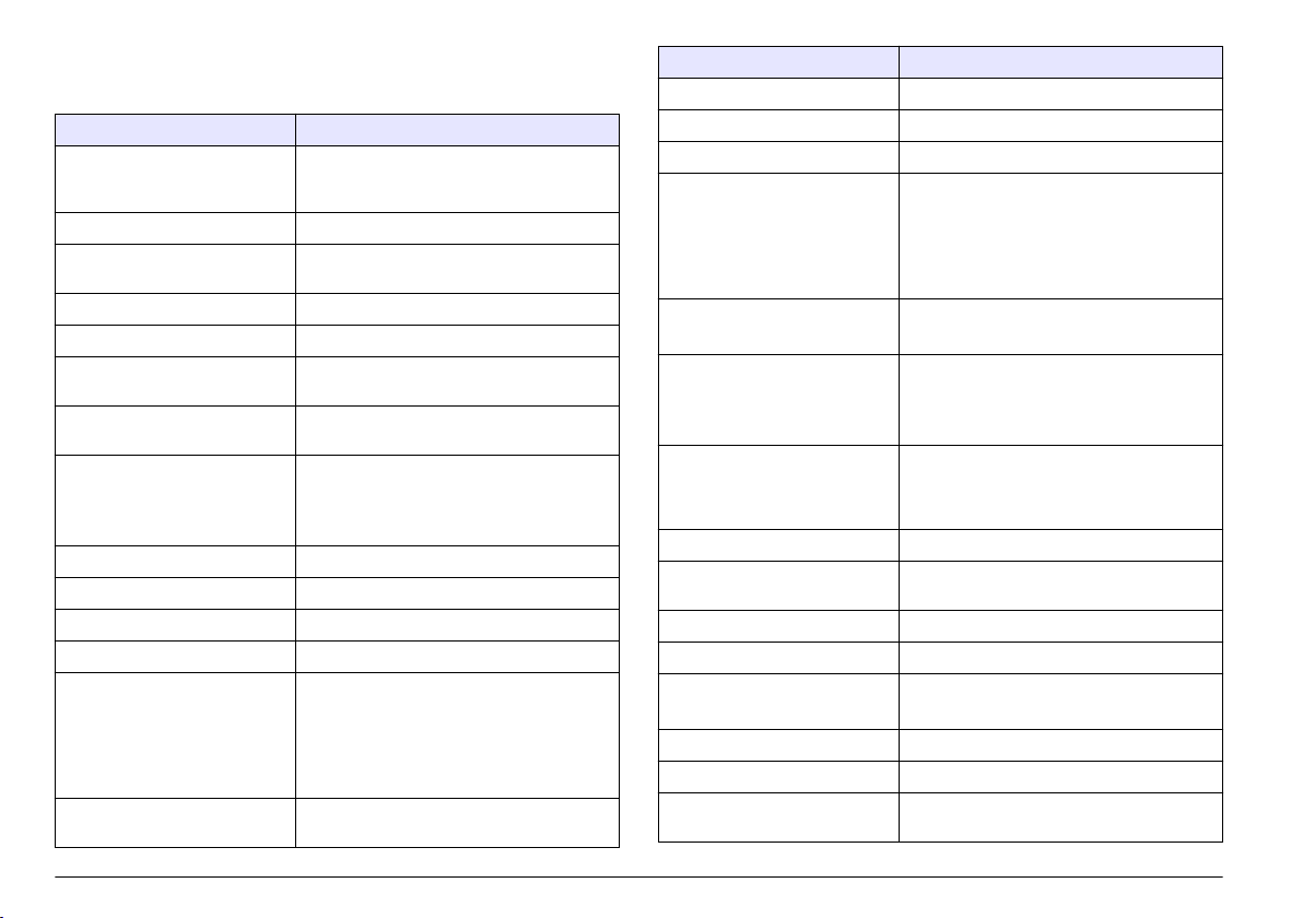
Specifications
Specifications are subject to change without notice.
Specification Details
Dimensions (W x D x H) 248 x 114 x 302 mm (9.75 x 4.50 x 11.88 in.) with
sensor and mounting brackets
Enclosure NEMA 4X
Light source 780 nm, 5 mW class 3B laser diode; 30,000 hours
lifetime
Detector Photodiode
Display LCD, 4-line x 16-character
Port sizes Two compression fittings for 0.25-in. OD inlet and
outlet tubing
Wetted materials Fused silica, Viton (fluorocarbon) and Kynar (PVDF)
Flow cell WPC-21: 600 x 600 µm fused silica with AR
coatings
WPC-22: 800 x 800 µm fused silica with AR
coatings
Weight 2.25 kg (5 lb)
Installation category II
Protection class I
Pollution degree 2
Operating environment WPC-21: 5 to 40 °C (41 to 104 °F), 5 to 90% relative
humidity, non-condensing
WPC-22: 5 to 45 °C (41 to 113 °F), 5 to 90% relative
humidity, non-condensing
Storage environment –20 to 60 °C (–4 to 140 °F), 98% relative humidity,
non-condensing (maximum)
Altitude 2000 m (6562 ft) maximum
Power requirements 230 VAC ±15% , 20 VA, 50/60 Hz
Specification Details
Detection method Light blocking
Calibration WPC-21: Factory calibrated at flow rate of
50 mL/minute, NIST traceable, eight particle sizes
WPC-22: Factory calibrated at flow rate of
100 mL/minute, NIST traceable, eight particle sizes
Particle sizes WPC-21: 1.3, 2, 3, 5, 7, 10, 15 and 25 µm
WPC-22: 2, 5, 7, 10, 15, 25, 50 and 100 µm
Coincidence fields WPC-21: 10% loss at 25,000 particles/mL
WPC-22: 10% loss at 15,000 particles/mL
Number of channels Two channels; Channel 1: smallest particle size,
Channel 2: one of the other seven channel sizes
(fixed) or all seven particle sizes (scrolling)
Measurement units Number of particles per mL
Sensor resolution Less than 10% at 10 µm as described in ASTM-
F658-87
Sensor counting efficiency Meets JIS 9925 B-1997 standards
Sample pressure 8.3 bar (120 psi) maximum
Sample flow rate WPC-21: 45–55 mL/minute
WPC-22: 90–110 mL/minute
Sample temperature 0 to 50 °C (32 to 122 °F), non-freezing
Digital input One; 0–10 VDC, ± 24 VDC < 10 mA
Digital outputs Two; open collector (100 mA, 24 VDC maximum)
Analog inputs Two; 0–10 VDC
Analog outputs 2 channels: 4–20 mA
Communications RS485 (protocol: MODBUS) or RS232, 19 AWG
twisted shielded pair wire
English 3
Page 4
Specification Details
Data storage 100 records
Certifications CE (Low voltage Directive)
General information
In no event will the manufacturer be liable for direct, indirect, special,
incidental or consequential damages resulting from any defect or
omission in this manual. The manufacturer reserves the right to make
changes in this manual and the products it describes at any time, without
notice or obligation. Revised editions are found on the manufacturer’s
website.
Safety information
N O T I C E
The manufacturer is not responsible for any damages due to misapplication or
misuse of this product including, without limitation, direct, incidental and
consequential damages, and disclaims such damages to the full extent permitted
under applicable law. The user is solely responsible to identify critical application
risks and install appropriate mechanisms to protect processes during a possible
equipment malfunction.
Please read this entire manual before unpacking, setting up or operating
this equipment. Pay attention to all danger and caution statements.
Failure to do so could result in serious injury to the operator or damage
to the equipment.
Make sure that the protection provided by this equipment is not impaired.
Do not use or install this equipment in any manner other than that
specified in this manual.
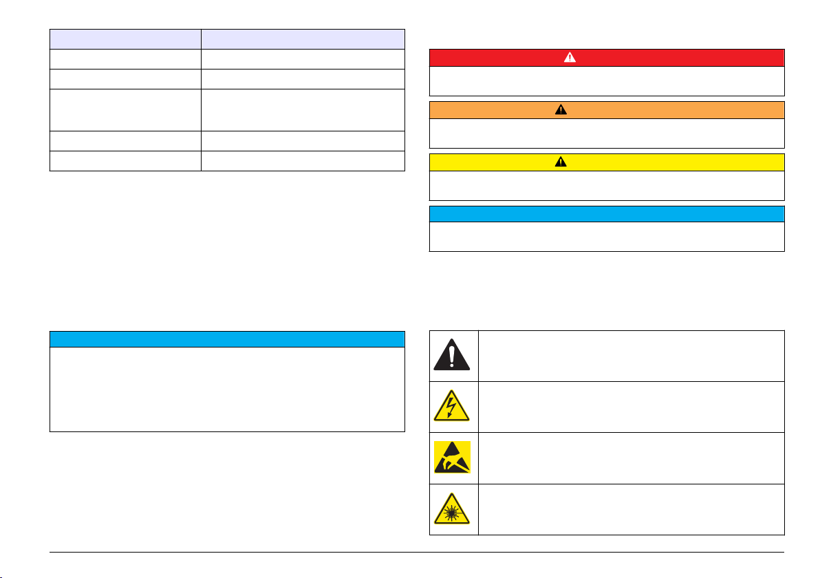
Use of hazard information
Indicates a potentially or imminently hazardous situation which, if not avoided, will
result in death or serious injury.
D A N G E R
W A R N I N G
Indicates a potentially or imminently hazardous situation which, if not avoided,
could result in death or serious injury.
Indicates a potentially hazardous situation that may result in minor or moderate
injury.
Indicates a situation which, if not avoided, may cause damage to the instrument.
Information that requires special emphasis.
C A U T I O N
N O T I C E
Precautionary labels
Read all labels and tags attached to the instrument. Personal injury or
damage to the instrument could occur if not observed. A symbol on the
instrument is referenced in the manual with a precautionary statement.
This symbol, if noted on the instrument, references the instruction
manual for operation and/or safety information.
This symbol, when noted on a product enclosure or barrier, indicates
that a risk of electrical shock and/or electrocution exists.
Delicate internal electronic components can be damaged by static
electricity, resulting in degraded performance or eventual failure.
This symbol indicates a laser device is used in the equipment.
4 English
Page 5
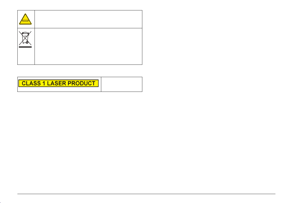
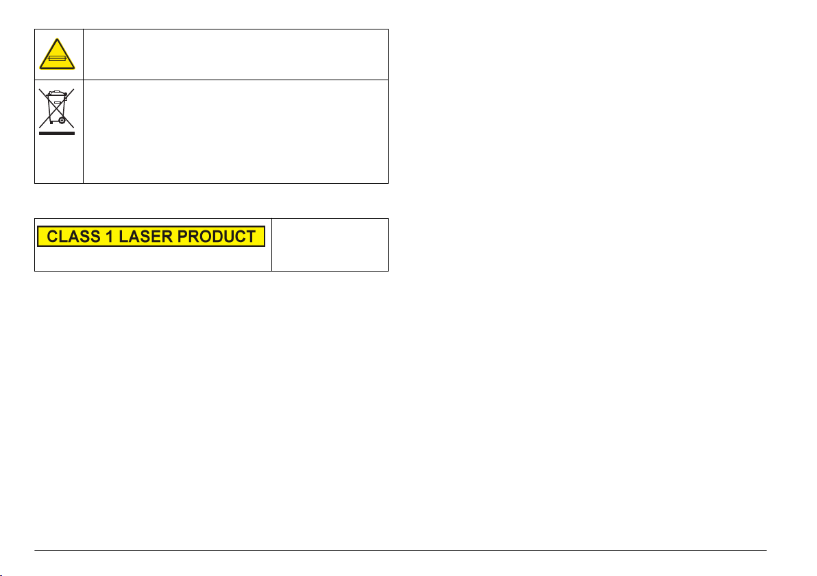
This symbol identifies the location of a fuse or current limiting device.
Electrical equipment marked with this symbol may not be disposed of
in European public disposal systems after 12 August of 2005. In
conformity with European local and national regulations (EU Directive
2002/96/EC), European electrical equipment users must now return
old or end-of-life equipment to the Producer for disposal at no charge
to the user.
Note: For return for recycling, please contact the equipment producer or supplier
for instructions on how to return end-of-life equipment, producer-supplied
electrical accessories, and all auxillary items for proper disposal.
Compliance
This symbol indicates
that the instrument is a
Class 1 LASER product.
This product complies with IEC/EN 60825-1:2007 and 21 CFR
1040.10 except for deviations pursuant to Laser Notice No. 50, dated
June 24, 2007. FDA accession number: 9020917.
This product is also CE compliant. Contact the manufacturer for
complete compliance details.
Certification
Canadian Radio Interference-Causing Equipment Regulation,
IECS-003, Class A:
Supporting test records reside with the manufacturer.
This Class A digital apparatus meets all requirements of the Canadian
Interference-Causing Equipment Regulations.
Cet appareil numérique de classe A répond à toutes les exigences de la
réglementation canadienne sur les équipements provoquant des
interférences.
FCC Part 15, Class "A" Limits
Supporting test records reside with the manufacturer. The device
complies with Part 15 of the FCC Rules. Operation is subject to the
following conditions:
1. The equipment may not cause harmful interference.
2. The equipment must accept any interference received, including
interference that may cause undesired operation.
Changes or modifications to this equipment not expressly approved by
the party responsible for compliance could void the user's authority to
operate the equipment. This equipment has been tested and found to
comply with the limits for a Class A digital device, pursuant to Part 15 of
the FCC rules. These limits are designed to provide reasonable
protection against harmful interference when the equipment is operated
in a commercial environment. This equipment generates, uses and can
radiate radio frequency energy and, if not installed and used in
accordance with the instruction manual, may cause harmful interference
to radio communications. Operation of this equipment in a residential
area is likely to cause harmful interference, in which case the user will be
required to correct the interference at their expense. The following
techniques can be used to reduce interference problems:
1. Disconnect the equipment from its power source to verify that it is or
is not the source of the interference.
2. If the equipment is connected to the same outlet as the device
experiencing interference, connect the equipment to a different
outlet.
3. Move the equipment away from the device receiving the interference.
4. Reposition the receiving antenna for the device receiving the
interference.
5. Try combinations of the above.
Product overview
This instrument is used to continually monitor particle contamination in
water. Refer to Figure 1. This instrument is typically used to monitor
municipal, industrial and private water treatment facilities.
This instrument has two channels. Channel 1 monitors the smallest
particle size. Channel 2 can be configured to monitor one of the other
English 5
Page 6
seven particle sizes (fixed) or all seven particle sizes (scrolling). Refer to
Specifications on page 3 for the particle sizes monitored.
This instrument can be used as an individual unit (stand alone) or in a
network of units connected through AQUARIUS software or customer
supplied software. For information about the AQUARIUS data acquisition
software, refer to the AQUARIUS documentation.
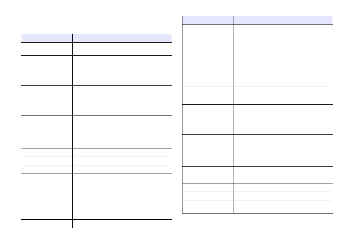
Figure 1 Instrument overview
Product components
Make sure that all components have been received. Refer to Figure 2. If
any items are missing or damaged, contact the manufacturer or a sales
representative immediately.
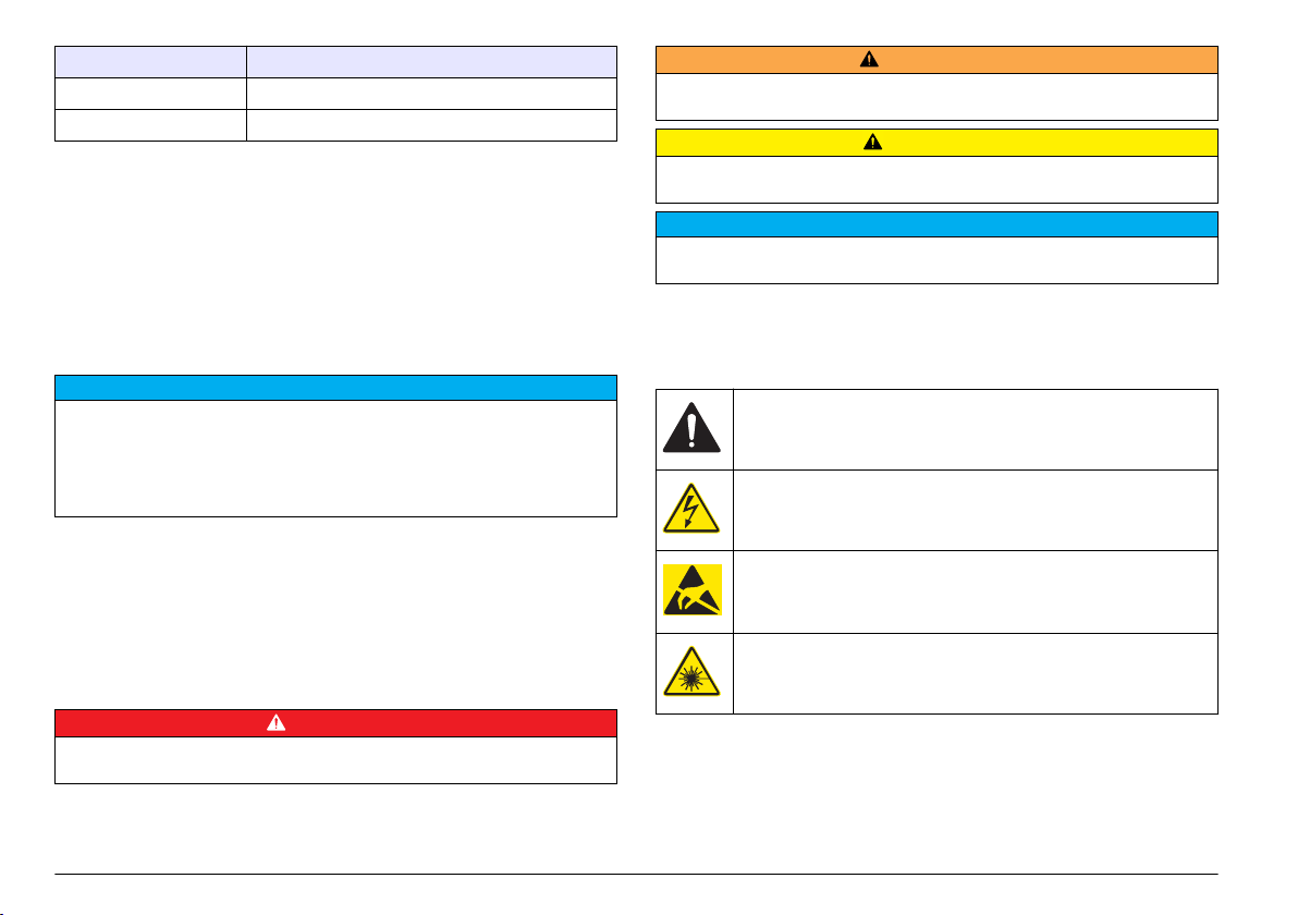
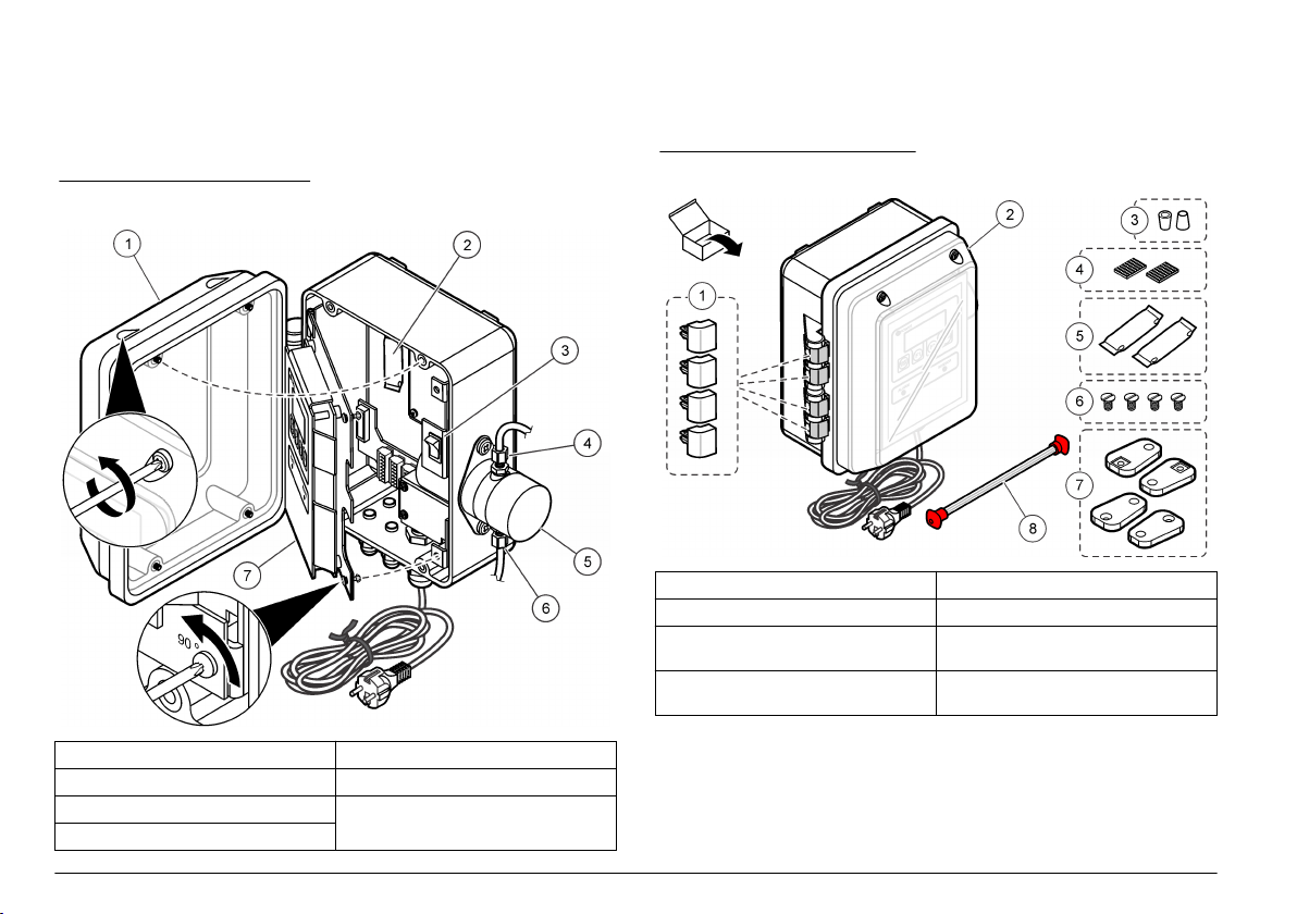
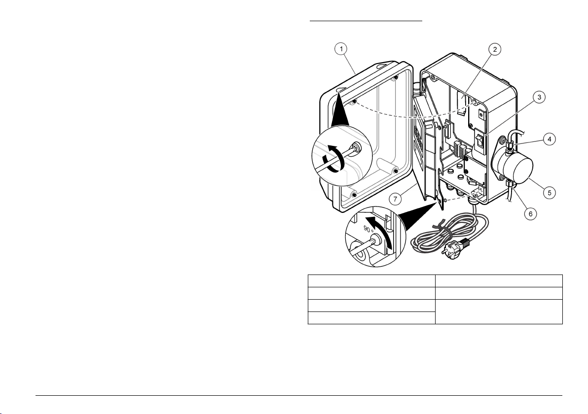
Figure 2 Product components
1 Hinge retainers, replacements (4x) 5 Desiccant packs (2x)
2 WPC-21 or WPC-22 6 Wall mounting brackets screws (4x)
3 6 mm ferrule adapters for 0.25-in.
compression fitting (2x)
4 Velcro adhesive strips for desiccant
packs (2x)
7 Wall mounting brackets (4x)
8 Cleaning brush kit with two cleaning
brushes
1 Enclosure door 5 Sensor assembly
2 Desiccant pack 6 Sample line fitting
3 Power switch 7 Electrical access panel and user
4 Drain line fitting
interface
6 English
Page 7
Installation
Installation guidelines
D A N G E R
Fire hazard. This product is not designed for use with flammable
liquids.
Install the instrument:
As near the sample source as possible to decrease analysis delay
•
•
In a clean, dry, well ventilated, temperature controlled location with
minimum vibration that does not receive direct exposure to sunlight
• In an environmental enclosure that supplies protection from
precipitation and direct sunlight, good ventilation and temperature
control if installed outdoors
• In a location where the power switch and power cord are visible and
easily accessible
• In a location where there is sufficient clearance around it to make
plumbing and electrical connections
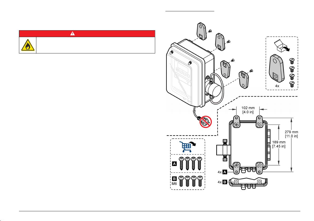
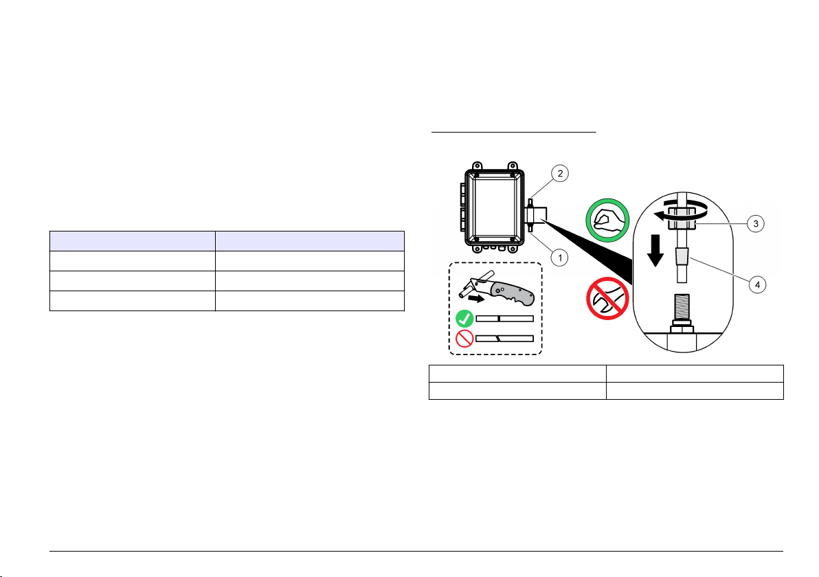
Mechanical installation
Attach the instrument to a wall
Attach the instrument upright and level on a flat, vertical surface. Refer
to the illustrated steps in Figure 3. Mounting hardware is supplied by the
user.
The sample flow must always be against gravity to prevent bubbles from
being trapped in the sensor. Flow is from the bottom to the top of the
sensor subassembly.
Note: The instrument can be attached to an existing panel. Install screws directly
to the rear panel or use the mounting hardware supplied.
Figure 3 Wall mounting
English 7
Page 8
Electrical installation
D A N G E R
Electrocution hazard. Always remove power to the instrument before
making electrical connections.
D A N G E R
Electrocution hazard. If this equipment is used outdoors or in
potentially wet locations, a Ground Fault Circuit Interrupt (GFCI/GFI)
device must be used for connecting the equipment to its main power
source.
Electrocution hazard. Protective Earth Ground (PE) connection is
required.
Use shielded twisted-pair cable for all electrical connections except input
power. Use of non-shielded cable may result in radio frequency emission
or susceptibility levels higher than the allowed levels.
To prevent shock hazards from ground currents in inadequate ground
systems, connect the shield at only the instrument end. Do not connect
the shield wire at both ends.
Electrical connections
Electrocution hazard. Do not use conduit to supply power. The
enclosure does not have a protective Earth Ground (PE) connection.
D A N G E R
D A N G E R
Make all electrical cable connections through the strain-relief fittings. To
keep the enclosure rating:
• Do not put more than one cable (or two wires) through a strain-relief
fitting.
•
Make sure that the strain-relief fittings that are unused have rubber
cable plugs in them. Use strain-relief fittings of the appropriate
environmental rating.
Obey all codes and regulations for wiring. Tighten the strain relief fittings
to hold the cables securely.
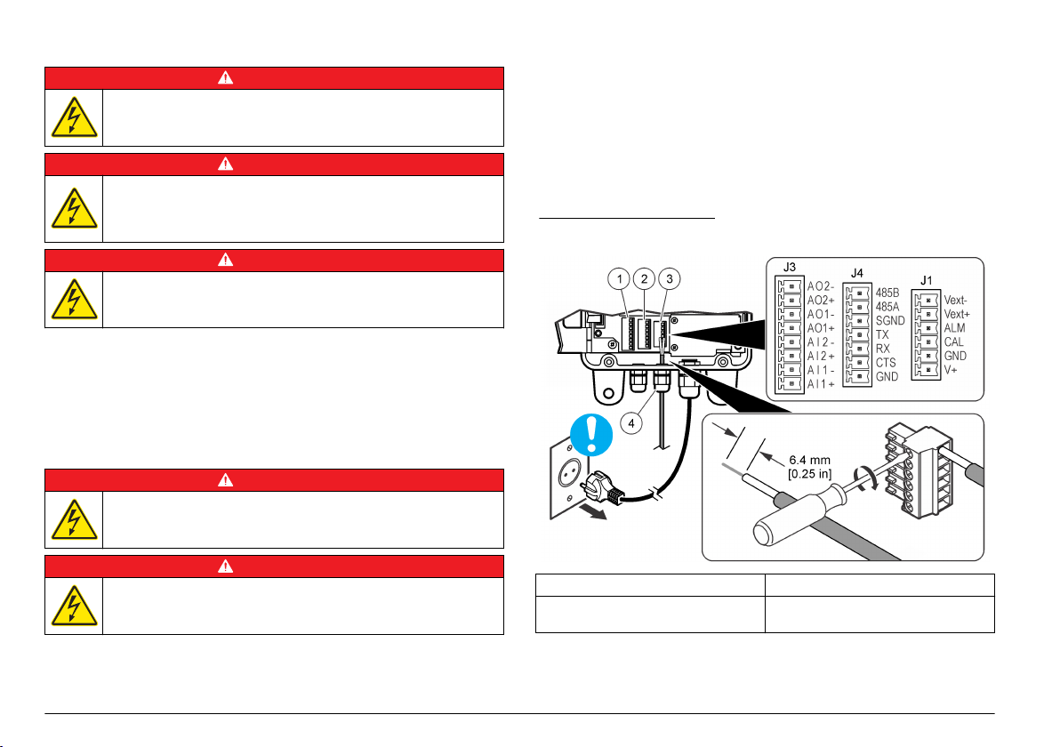
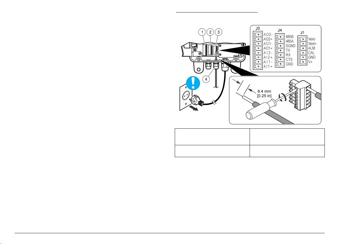
Figure 4 Wiring overview
D A N G E R
Electrocution hazard. Always remove power to the instrument before
making electrical connections.
Figure 4 shows the wiring connections and general wiring procedure.
8 English
1 Analog input/output connections 3 Alarm connections (digital outputs)
2 Communication connections
(RS232 and RS485)
4 Strain-relief fitting for external
connections (4x)
Page 9
Connect the analog outputs (optional)
Two 4–20 mA analog outputs (AO1 and AO2) are available at the
J3 connector. The analog output signal is proportional to the counts/mL
of the channel. The counts/mL for Channel 1 is represented on AO1.
The counts/mL for Channel 2 is represented on AO2.
Connect a current receiving device to each analog output with
24–28 AWG wire. Refer to Table 1.
If the current receiving device(s) has a load resistor of 500 ohms or
more, supply external voltage (40 VDC maximum) to Vext– and Vext+ of
the J1 connector to supply sufficient voltage to the current receiving
device.
Table 1 Analog output connections (4–20 mA)
Pin Description
AO2– Neutral
AO2+ Positive
AO1– Neutral
AO1+ Positive
Connect the analog input (optional)
Two analog inputs (AI1 and AI2) are available on the J3 connector.
Connect auxiliary instruments (i.e., flow meters, turbidity meters,
pressure transducers, pH meter) to the analog inputs to show the
voltage supplied by the auxiliary instruments on the instrument display
(0–10 VDC). Refer to Identify the analog input values on page 15.
Connect an auxiliary instrument to each analog input with 22–24 AWG
wire. Use 19 AWG wire instead if the wire is 7.62 m (25 ft) long or more.
Refer to
Table 2.
Table 2 Analog input connections (0–10 VDC)
Pin Description
AI2– Neutral
AI2+ Positive
Table 2 Analog input connections (0–10 VDC) (continued)
Pin Description
AI1– Neutral
AI1+ Positive
Connect the digital input (optional)
One digital input is available on the J4 connector. Connect a flow
monitoring device to the digital input (CTS pin) to trigger a Flow alarm
when the voltage on the digital input is high or low, depending on the
Flow Alarm State setting. Refer to Configure the particle counter
on page 13 to configure the Flow Alarm State setting and enable the
Flow alarm.
Connect the flow monitoring device to the CTS pin with 24–28 AWG
wire.
Note:
The digital input is not available when the RS232 connection is used to
connect a printer or a computer.
Connect the digital outputs (optional)
Two digital outputs (ALM and CAL) are available on the J1 connector.
Refer to Table 3. Connect a compatible device such as a remote alarm
indicator or buzzer to the applicable digital output with 24–48 AWG wire.
The ALM pin and CAL pin are open collector outputs that supply a
ground connection when energized. Obey the digital output ratings in
Specifications on page 3.
Table 3 Digital output descriptions
Digital output Description
ALM pin Energizes when a Flow alarm or Count alarm is active. Refer to
CAL pin Energizes when a high or low calibration error is active.
Configure the particle counter on page 13 to configure the
Flow alarm and Count alarm.
English 9
Page 10
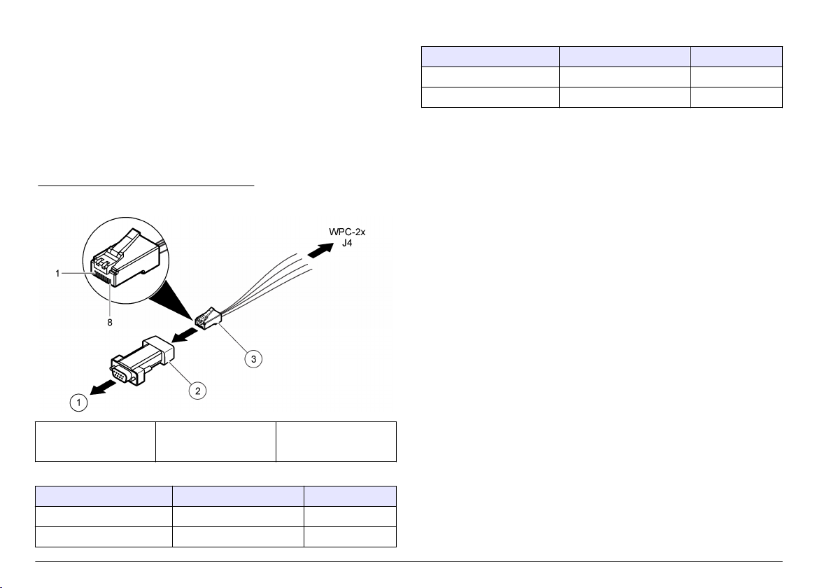
Connect a serial device (optional)
One RS232 connection is available on the J4 connector. Connect a
printer or the serial port of a computer (COM 1 or COM 2) to the
RS232 connection to send the buffered data to a printer or a computer.
Refer to Send the data log to a printer or computer on page 15.
If the optional RJ-45 to DB-9 converter is used, cut an RJ-45 cable and
then separate and identify the wires. Refer to Figure 5
for the RS232 wiring connections.
Note: The RS232 connection is not available when the digital input (CTS pin) is
used.
Figure 5 RJ-45 to DB-9 converter wiring
1 To PC or printer 2 RJ-45 to
DB-9 converter
(SA000070-01)
Table 4 RS232 connections
DB-9 pin RJ-45 pin J4 pin
Pin 2 RX Pin 3 TX
Pin 3 TX Pin 4 RX
. Refer to Table 4
3 RJ-45 cable (user
supplied)
Table 4 RS232 connections (continued)
DB-9 pin RJ-45 pin J4 pin
Pin 4 DTR Pin 5 CTS
Pin 5 GND Pin 8 GND
Supply power to an external device (optional)
+5 VDC or +12 VDC is available on JP1 to supply power to an external
device. +5 VDC is supplied when the jumper is across the +5V pin and
pin 2 of JP1. +12 VDC is supplied when the jumper is across the Vps pin
and pin 2 of JP1.
Note: The V+ pin and GND pin on the J1 connector are for Service use only.
Connect units in a network (optional)
Multiple units can be connected together in a network. Use the
RS485 connection of each unit and 19 AWG, twisted shielded pair wire
to connect the units together.
Notes:
• A maximum of 32 units in a network can be connected to one
RS485 network.
•
The host computer must have data acquisition software.
• The communication protocol is Modbus. Refer to the WPC Modbus
documentation on the manufacturer's website.
1. On the first unit:
a. Push the incoming cable from the RS232/RS485 converter
through a strain-relief fitting.
b. Push the outgoing cable through a strain relief fitting.
c. Connect the incoming and outgoing cable wires to the
J4 connector. Refer to Table 5.
2. On the second unit:
a. Push the incoming cable from the first unit through a strain-relief
fitting.
b. Push the outgoing cable through a strain relief fitting.
10 English
Page 11
c. Connect the incoming and outgoing cable wires to the
J4 connector. Refer to Table 5.
3. Do step 2 again for the third and remaining units until all the units
have incoming and outgoing connections. The last unit will not have
an outgoing cable.
Note: In a network installation, the outgoing cable from the previous unit is
always the incoming cable on the next unit.
4. On the last unit, install a jumper across JP2. Do not install a jumper
across JP2 on the other units.
5. Set the MODE option to N (network mode). Refer to the Date/MODE
option in Configure the particle counter on page 13.
6. Assign a unique address to each unit. Refer to the Unit ID option in
Configure the particle counter on page
13.
Table 5 RS485 connections
Wire J4 pin
– RS485A
+ RS485B
Shield SGND
Plumbing
Plumb the instrument
Items to collect:
• 6 mm OD opaque tubing
•
Two, 6 mm ferrules
Select tubing based on the worst case environmental conditions (e.g.,
temperature range, exposure to sunlight, contaminants in the air) and
the highest possible inlet pressure (maximum of 120 psi).
1. Remove the tubing from the sample line fitting and drain line fitting
and discard. Do not reuse the tubing for the sample line or drain line.
2. Connect a sample line to the sample line fitting on the body of the
instrument. Refer to Figure 6.
3. Connect a drain line to the drain line fitting on the body of the
instrument. Refer to Figure 6.
4. Install a Y-strainer in the sample line as necessary to prevent large
particles from entering the sensor which will result in a blockage.
5. Install a manual isolation valve in the sample line so that the flow to
the instrument can be stopped as necessary.
Figure 6 Plumb the instrument
1 Sample line fitting 3 Plastic nut
2 Drain line fitting 4 Ferrule, 6 mm
Sample line guidelines
Select a good, representative sampling point for the best instrument
performance. The sample must be representative of the entire system.
To prevent erratic readings:
Collect samples from locations that are sufficiently distant from points
•
of chemical additions to the process stream.
•
Make sure that the samples are sufficiently mixed.
• Make sure that all chemical reactions are complete.
English 11
Page 12
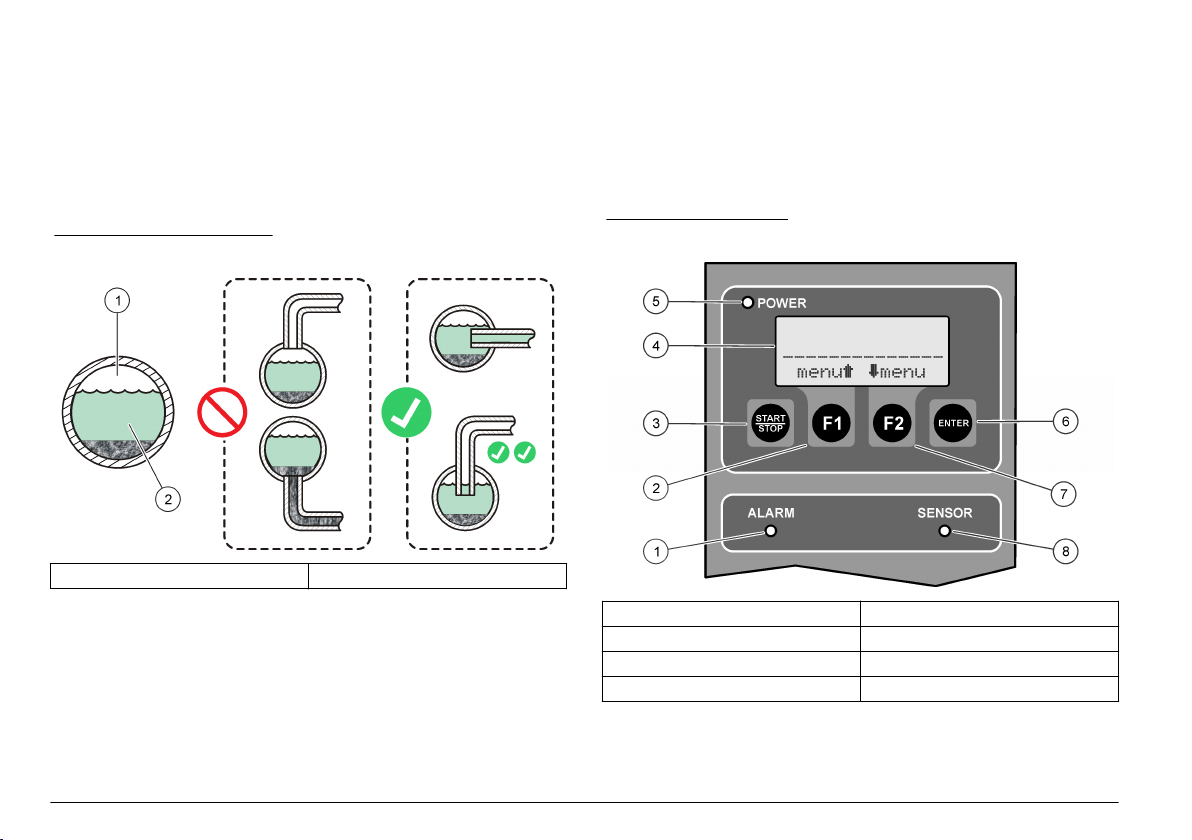
Connect the sample stream
Install the sample line into a larger process pipe to minimize interference
from air bubbles or pipeline bottom sediment. A sample line that goes
into the center of a process pipe is best.
Figure 7 shows examples of good and bad methods of sample line
installation into a process pipe.
Keep the sample line as short as possible to decrease analysis delay.
Sediment can collect in long sample lines.
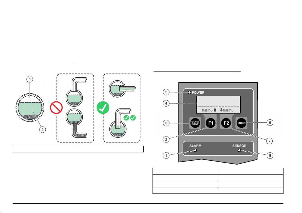
Figure 7 Sampling methods
1 Air 2 Sample flow
4. Close the enclosure door. Tighten all four captive screws that attach
the enclosure door.
User interface and navigation
User interface
Figure 8 shows the display, keypad and indicator lights. Refer to Table 6
for key descriptions. Refer to Table 7 for indicator light descriptions.
Figure 8 User interface
Startup
Set the power to on
1. Connect the power cord to an electrical outlet with earth ground.
2. Open the enclosure door. Loosen all four captive screws that attach
the enclosure door.
3. Set the power switch to on.
12 English
1 Alarm light 5 Power light
2 F1 key 6 ENTER key
3 START/STOP key 7 F2 key
4 Display 8 Sensor light
Page 13
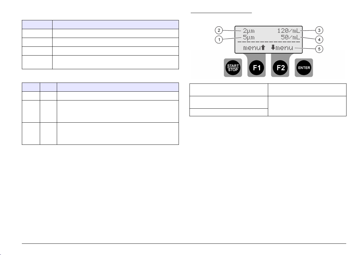
Table 6 Key descriptions
Key Description
START/STOP Starts or stop particle counting
F1 Use to navigate through the menus and change settings
F2 Use to navigate through the menus and change settings
ENTER Confirm, enter or select. Push to save the current count to the
buffer (stand alone mode only).
Table 7 Indicator light descriptions
Light Color Description
Power Green There is power to the instrument and the power switch is on.
Alarm Red Steady on—a network alarm is active.
Flashes—a Count alarm or a Flow alarm is active.
Refer to Troubleshooting on page 18.
Sensor Yellow Steady on—a high calibration error is active.
Flashes—a low calibration error is active.
Refer to Troubleshooting on page 18.
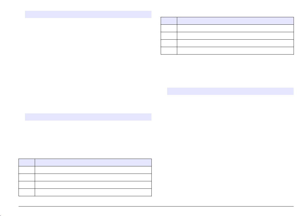
Display description
Figure 9 shows the information shown on the display.
When a calibration error or Flow alarm occurs, an error message shows
on the display. Refer to Error messages on page 19.
Figure 9 Counting screen
1 Particle size monitored on Channel2 4 Particle count on Channel 2
2 Particle size monitored on Channel1 5 F1 and F2 soft key functions
3 Particle count on Channel 1
Operation
Configure the particle counter
The particle counter can be configured for stand alone or network
operation. In network mode, the data buffering, printing and the Channel
2 Size settings are changed with the network software so these settings
are not available on the instrument display.
1. Push the F1 to select an option, then push ENTER. The current
setting(s) shows.
English 13
Page 14

Stand alone mode only
Option Description
Intervals BUF—Set the buffer (data log) interval. Options: OFF
(disabled), 30 seconds, 1, 5, 10, 30 or 60 minutes.
At the end of each buffer interval, the date, time, sensor
status and count are saved to the buffer. The buffer
holds a maximum of 100 records. When the buffer is full,
new data is saved over the oldest data.
Note: If a serial printer is attached, every time data is saved to the
buffer that data is also sent to the printer.
SCRL—Set the scroll interval. Options: OFF (disabled),
30 seconds, 1, 5, 10, 30 or 60 minutes.
At the end of each scroll interval, the instrument starts to
monitor the next calibrated particle size on Channel 2.
When disabled, the particle size monitored on Channel
2 is the Channel 2 Size setting.
Note: No data will be saved to the buffer if the buffer interval is
longer than the scroll interval.
Buff Count/Print
Buff/Download
Refer to Send the data log to a printer or computer
on page 15. The Buff Count value shown is the
number of entries in the buffer (data log).
Buff Count/View
Buffer/ Delete
Buffer
Refer to View or delete the buffer (data log)
on page 15. The Buff Count value shown is the
number of entries in the buffer (data log).
Count Alarms Set the minimum number of particles that will trigger a
Count alarm on Channel 1 and Channel 2. To disable,
set to 0.
A1—Count limit for Channel 1
A2—Count limit for Channel 2
Push INC to change the selected digit. Push the RIGHT
arrow to select the next digit.
Network mode only
Option Description
Unit ID = 1 Set a unique address for the instrument. Options: 1 to 247.
Address 0 cannot be used. This option only shows when the
MODE option is set to N (network mode).
Stand alone and Network mode
Option Description
Analog Count
Out/Upper 1/Lower
1
Set the count limits (range) for the analog output
(4–20 mA) for Channel 1.
UL1—Upper count limit that will correspond to a
20 mA output signal
LL1—Lower count limit that will correspond to a 4 mA
output signal
Analog Count
Out/Upper 2/Lower
2
Set the count limits (range) for the analog output
(4–20 mA) for Channel 2.
UL2—Upper count limit that will correspond to a
20 mA output signal
LL2—Lower count limit that will correspond to a 4 mA
output signal
Channel 2 Size Push the UP and DOWN arrow keys to set the particle
size that will be monitored on Channel 2 when the
scroll interval is set to OFF.
Flow Rate/Flow
Alarm
RATE—Enter the flow rate
ALM—Enable (ON) or disable (OFF) the flow alarm. If
a flow monitoring device is available, the flow alarm is
monitored on the digital input (CTS pin).
Flow Alarm State
Active
Set the flow alarm to trigger on a high or low voltage
input on the CTS pin depending on the active state of
the flow alarm device. Options: HI or LO.
If the Flow Alarm State Active option is set to HI, a
high voltage input (> 2.5 VDC) on the CTS pin from
the flow monitoring device triggers a Flow alarm and
0 V identifies a normal flow.
Input 1/Input 2 Refer to Identify the analog input values on page 15.
14 English
Page 15
Option Description
Contrast/Beep CON—Adjust the contrast
BEP—Enable (ON) or disable (OFF) the audible beep
Date/MODE Date—Enter the date and time (24 hour format)
MODE—Set the mode. Options: S (stand alone mode)
or N (network mode)
Send the data log to a printer or computer
The data in the buffer (data log) can be sent to an attached printer or
computer. Refer to Connect a serial device (optional) on page 10.
1. Set the printer and/or computer serial port to 9600 baud, 8 data, No
parity, 1 stop bit and no flow control.
Note:
The computer or printer will not receive complete transmissions if the
device cannot continuously receive at 9600 baud.
2. Push the F1 until "Buff Count/Print Buff/Download" shows, then push
ENTER.
3. Select an option. To exit, push ENTER.
Option Description
PRT Send the data in the buffer (data log) to the attached printer or
terminal display. The oldest data is sent first. Refer to Table 11 for
the sensor status codes.
DNLD Send the data in the buffer (data log) to the attached computer.
Refer to Table 11 for the sensor status codes.
Table 11 Status codes (binary)
Code Description
1 Sensor error
2 CH1 count alarm
3 Sensor error and CH1 count alarm
4 CH2 count alarm
Table 11 Status codes (binary) (continued)
Code Description
5 Sensor error and CH2 count alarm
6 CH1 and CH2 count alarms
7 Sensor error, CH1 count alarm and CH2 count alarm
8 Flow alarm or digital input alarm
View or delete the buffer (data log)
1. Push the F1 until "Buff Count/View Buffer/Delete Buffer" shows, then
push ENTER.
2. Select an option. To exit, push ENTER.
Option Description
VIEW Show the data in the buffer (data log). The most recent data shows
first. The status codes shown are:
A—One of the channels was over the count alarm setting for the
channel.
S—It may be necessary to clean the sensor flow cell.
To go backwards, push BAK. To go forward, push NXT. To exit,
push ENTER.
DEL Erase all the data in the buffer (data log). Push YES to confirm or
NO to exit.
Identify the analog input values
Push the F1 until "Input 1/Input 2" shows, then push ENTER
voltage supplied by the auxiliary instrument connected to each analog
input shows. This information is not buffered in stand alone mode but it
can be retrieved in network mode.
. The
English 15
Page 16
Calibration
The instrument cannot be calibrated by the user. Contact the
manufacturer for
instrument calibration. Refer to the label on the
instrument for the calibration due date.
Maintenance
W A R N I N G
Multiple hazards. Only qualified personnel must conduct the tasks
described in this section of the document.
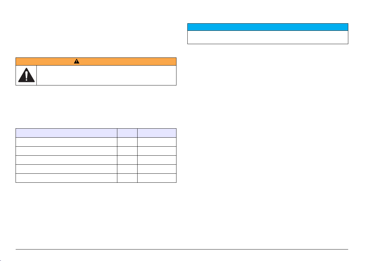
Clean the sensor flow cell
N O T I C E
Do not insert the cleaning brush into the sample line fitting when the sensor flow
cell is dry or damage to the sensor flow cell may occur.
Periodically, clean the sensor flow cell. In addition, clean the sensor flow
cell before use if the instrument has not been used for a long time.
Items to collect:
• Factory supplied cleaning brush
•
Clean water
Maintenance schedule
Table 12 shows the recommended schedule of maintenance tasks.
Facility requirements and operating conditions may increase the
frequency of some tasks.
Table 12 Maintenance schedule
Task 1 year As necessary
Calibration on page 16 X
Clean the instrument on page
Clean the sensor flow cell on page 16 X
Replace the desiccant pack on page 17 X
Replace a fuse on page 17 X
1
Required to keep compliance with JIS B 9925-1997 standards
16 X
1
Clean the instrument
Clean the exterior of the instrument with a moist cloth and a mild soap
solution and then wipe the instrument dry.
16 English
1. Open the enclosure door. Loosen all four captive screws that attach
the enclosure door.
2. Set the power switch to off.
3. Stop the flow of water to the instrument.
4. Remove the sample line and drain line from the compression fittings.
5. Connect the sample line to the compression fitting on top of the
sensor assembly.
6. Start the flow of water to the instrument. After 30 seconds, stop the
flow.
7. Remove the sample line from the compression fitting.
8. Clean the sensor flow cell.
a. Pour clean water into the compression fitting on top of the sensor
assembly. The water will drain from the sample line compression
fitting.
b. Insert the cleaning brush into the compression fitting. Gently
move the brush up and down two or three times. Refer to
Figure 10.
c. Pour clean water into the compression fitting on top of the sensor
assembly. This will rinse out any material that was loosened by
the brush.
d. Pour clean water over the cleaning brush to rinse out any
material.
Page 17
9. Connect the sample line and drain line tubing. Refer to Plumb the
instrument on page 11.
10. Start the flow of water to the instrument.
11. Set the power switch to on.
12. Close the enclosure door. Tighten all four captive screws that attach
the enclosure door.
Figure 10 Clean the sensor flow cell
Replace the desiccant pack
Replace the desiccant pack when the color of the crystals in the
desiccant pack change from blue to pink. Refer to Figure 1 on page
the location of the desiccant pack.
A desiccant pack must be used to prevent moisture build up in the
instrument enclosure. This will help prevent corrosion of sensitive
electrical connections and help prevent the collection of condensation in
the sensor assembly.
Items to collect:
• Desiccant pack
• Velcro adhesive strip
6 for
1. Open the enclosure door. Loosen all four captive screws that attach
the enclosure door.
2. Set the power switch to off.
3. Open the electrical access panel. Turn the two ¼-turn captive screws
only ¼ turn.
4. Replace the desiccant pack.
a. Pull the used desiccant pack off the Velcro strip on the rear panel
and discard.
b. Put an adhesive Velcro strip on a new desiccant pack.
c. Push the desiccant pack on the Velcro strip on the rear panel.
5. Close and attach the electrical access panel with the two ¼-turn
screws.
6. Set the power switch to on.
7. Close the enclosure door. Tighten all four captive screws that attach
the enclosure door.
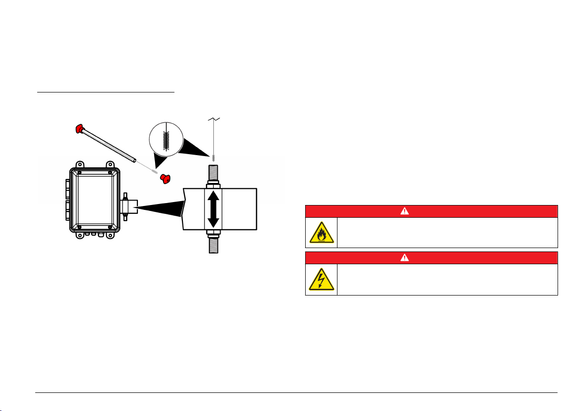
Replace a fuse
D A N G E R
Fire hazard. Use the same type and current rating to replace fuses.
D A N G E R
Electrocution hazard. Remove all power from the instrument and relay
connections before this maintenance task is started.
Items to collect:
• Fuse, 5 x 20 mm T, 0.500 mA, 250 V
• Phillips screwdriver
1. Open the enclosure door. Loosen all four captive screws that attach
the enclosure door.
2. Set the power switch to off.
English 17
Page 18
3. Open the electrical access panel. Turn the two ¼-turn captive screws
only ¼ turn.
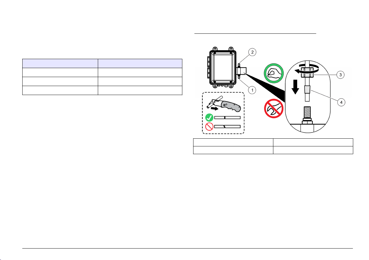
4. Replace the fuse. Refer to the illustrated steps in Figure 11.
5. Assemble the instrument. Do the illustrated steps in Figure 11 in
reverse order.
6. Close and attach the electrical access panel with the two ¼-turn
screws.
7. Set the power switch to on.
8. Close the enclosure door. Tighten all four captive screws that attach
the enclosure door.
Figure 11 Replace a fuse
Troubleshooting
Problem Possible cause Solution
POWER light
does not come
on
ALARM light on A network alarm is active.
ALARM light
flashes
SENSOR lightonA high calibration error is
SENSOR light
flashes
Two or more
instruments do
not respond to
the monitoring
software
There is no power to the
instrument or the power switch
is set to off.
Note: A network alarm is only
activated and deactivated by the
network software.
A Count alarm (stand alone
instrument only) or a Flow
alarm is active.
Note: If a Count alarm is active, the
ALARM light and the channel with an
alarm flashes on the display.
active. The sensor is
contaminated or the laser diode
is losing power.
A low calibration error is active.
The photodiode is saturated
and should be cleaned,
adjusted or replaced.
Two or more instruments have
the same address. The
instruments with the same
address will not respond to the
monitoring software.
Make sure that the power
switch is set to on. Make
sure that there is power to
the instrument.
Refer to Configure the
particle counter on page 13
to configure the Count
alarm settings.
Clean the flow cell. Refer to
Clean the sensor flow cell
on page 16.
If the high calibration error
continues, contact technical
support.
Clean the flow cell. Refer to
Clean the sensor flow cell
on page 16.
If the low calibration error
continues, contact technical
support.
Switch the monitoring
software off and assign a
unique address to the
instruments that have the
same address. Refer to the
Unit ID option in Configure
the particle counter
on page 13.
—
18 English
Page 19
Error messages
Accessories
Message Possible cause Solution
CAL A high or low calibration
error is active.
FLOW The external flow monitoring
device has triggered a Flow
alarm.
Clean the flow cell. Refer to Clean the
sensor flow cell on page 16.
If the calibration error continues,
contact technical support.
Refer to Connect the digital input
(optional) on page 9.
Replacement parts and accessories
W A R N I N G
Personal injury hazard. Use of non-approved parts may cause
personal injury, damage to the instrument or equipment malfunction.
The replacement parts in this section are approved by the
manufacturer.
Note: Product and Article numbers may vary for some selling regions. Contact the
appropriate distributor or refer to the company website for contact information.
Replacement parts
Description Item no.
Ferrule, 6 mm, adapter for 0.25-in. compression fitting MP000147-01
Cleaning brush kit, with two 1 µm brushes, for WPC-22 SA000120-02
Cleaning brush kit, with two 2 µm brushes, for WPC-21 SA000120-01
Desiccant kit, with two desiccant packs and two Velcro
adhesive labels
Fuse, 5 x 20 mm T, 0.500 mA, 250 V 500-150-0050
Power cord, 230 VAC 510667
Strain-relief fitting for power cord VP752401
Strain-relief fitting for external connections 570-730-2212
SA000180-01
Description Item no.
AQUARIUS software CS200011
RJ-45 to DB-9 converter SA000070-01
RS485/RS422 to USB converter 5920400
Tubing, opaque, 0.25-in. OD, black PTFE VP792021
Weir flow controller for flow adjustment 2081335-1
English 19
Page 20
Technische Daten
Änderungen vorbehalten.
Technische Daten Details
Abmessungen (B x T x H) 248 mm x 114 mm x 302 mm (9.75 x 4.50 x
Gehäuse NEMA 4X
Lichtquelle 780 nm, 5 mW Laserdiode Klasse 3B;
Detektor Fotodiode
Display LCD, 4-zeilig mit 16 Zeichen
Probenanschluss Abmessungen Zwei Klemmverschraubungen mit 0,25 Zoll
Medienberührte Materialien Quarzglas, Viton (Fluorkohlenstoff) und
Durchflusszelle WPC-21: 600 x 600 µm Quarzglas mit AR-
Gewicht 2.25 kg (5 lbs)
Einbaukategorie IIF
Schutzklasse I
Verschmutzungsgrad 2
Betriebsumgebungstemperatur WPC-21: 5 bis 40 °C (41 bis 104 °F), 5 bis
Lagerungsumgebungstemperatur –20 bis 60 °C (–4 bis 140 °F), 98"% relative
11.88 Zoll) mit Sensor und
Montagehalterungen
Lebensdauer 30.000 Stunden
Außendurchmesser-Zu- und -Ablaufschlauch
Kynar (PVDF)
Beschichtung
WPC-22: 800 x 800 µm Quarzglas mit AR-
Beschichtung
90 % relative Luftfeuchte, nicht
kondensierend
WPC-22: 5 bis 45 °C (41 bis 113 °F), 5 bis
90 % relative Luftfeuchte, nicht
kondensierend
Luftfeuchte, nicht kondensierend (maximal)
Technische Daten Details
Einsatzhöhe Maximal 2000 m (6562 ft)
Stromversorgung 230 VAC ±15 % , 20 VA, 50/60 Hz
Messverfahren Lichtblockung
Kalibrierung WPC-21: Werkseitig kalibriert mit
Partikelgröße WPC-21: 1,3, 2, 3, 5, 7, 10, 15 und 25 µm
Koinzidenzverlust WPC-21: 10 % Verlust bei
Anzahl der Kanäle Zwei Kanäle; Kanal 1: kleinste Partikelgröße,
Maßeinheiten Anzahl der Partikel pro ml
Sensorauflösung Weniger als 10 % bei 10 µm wie in ASTM-
Sensorzählereffizienz Erfüllt JIS 9925 B-1997-Standards
Probendruck Maximal 8,3 bar (120 psi)
Probendurchflussmenge WPC-21: 45-55 ml/Minute
Probentemperatur 0 bis 50 °C (32 bis 122 °F), frostsicher
Digitaler Eingang Ein; 0-10 VDC, ± 24 VDC < 10 mA
Digitalausgänge Zwei, offener Kollektor (100 mA, maximal
Durchflussrate von 50 ml/Minute, NISTkonform, acht Partikelgrößen
WPC-22: Werkseitig kalibriert mit
Durchflussrate von 100 ml/Minute, NISTkonform, acht Partikelgrößen
WPC-22: 2, 5, 7, 10, 15, 25, 50 und 100 µm
25.000 Partikeln/ml
WPC-22: 10 % Verlust bei
15.000 Partikeln/ml
Kanal 2: eine der anderen sieben
Kanalgrößen (fest) oder alle sieben
Partikelgrößen (blätternd)
F658-87 beschrieben
WPC-22: 90-110 ml/Minute
24 VDC)
20 Deutsch
Page 21
Technische Daten Details
Analogeingänge Zwei, 0-10 VDC
Analogausgänge 2 Kanäle: 4-20 mA
Datenübertragung RS485 (Protokoll: MODBUS) oder RS232,
Datenspeicher 100 Datensätze
Zertifizierungen CE (Niederspannungsrichtlinie)
geschirmtes 19-AWG-Kabel mit verdrilltem
Adernpaar
Allgemeine Informationen
Der Hersteller ist nicht verantwortlich für direkte, indirekte,
versehentliche oder Folgeschäden, die aus Fehlern oder
Unterlassungen in diesem Handbuch entstanden. Der Hersteller behält
sich jederzeit und ohne vorherige Ankündigung oder Verpflichtung das
Recht auf Verbesserungen an diesem Handbuch und den hierin
beschriebenen Produkten vor. Überarbeitete Ausgaben der
Bedienungsanleitung sind auf der Hersteller-Webseite erhältlich.
Sicherheitshinweise
H I N W E I S
Der Hersteller ist nicht für Schäden verantwortlich, die durch Fehlanwendung
oder Missbrauch dieses Produkts entstehen, einschließlich, aber ohne
Beschränkung auf direkte, zufällige oder Folgeschäden, und lehnt jegliche
Haftung im gesetzlich zulässigen Umfang ab. Der Benutzer ist selbst dafür
verantwortlich, schwerwiegende Anwendungsrisiken zu erkennen und
erforderliche Maßnahmen durchzuführen, um die Prozesse im Fall von möglichen
Gerätefehlern zu schützen.
Bitte lesen Sie dieses Handbuch komplett durch, bevor Sie dieses Gerät
auspacken, aufstellen oder bedienen. Beachten Sie alle Gefahren- und
Warnhinweise. Nichtbeachtung kann zu schweren Verletzungen des
Bedieners oder Schäden am Gerät führen.
Stellen Sie sicher, dass die durch dieses Messgerät bereitgestellte
Sicherheit nicht beeinträchtigt wird. Verwenden bzw. installieren Sie das
Messsystem nur wie in diesem Handbuch beschrieben.
Bedeutung von Gefahrenhinweisen
G E F A H R
Kennzeichnet eine mögliche oder drohende Gefahrensituation, die, wenn sie
nicht vermieden wird, zum Tod oder zu schweren Verletzungen führt.
Kennzeichnet eine mögliche oder drohende Gefahrensituation, die, wenn sie
nicht vermieden wird, zum Tod oder zu schweren Verletzungen führen kann.
Kennzeichnet eine mögliche Gefahrensituation, die zu geringeren oder
moderaten Verletzungen führen kann.
Kennzeichnet eine Situation, die, wenn sie nicht vermieden wird, das Gerät
beschädigen kann. Informationen, die besonders beachtet werden müssen.
W A R N U N G
V O R S I C H T
H I N W E I S
Warnhinweise
Lesen Sie alle am Gerät angebrachten Aufkleber und Hinweise.
Nichtbeachtung kann Verletzungen oder Beschädigungen des Geräts
zur Folge haben. Im Handbuch werden auf die am Gerät angebrachten
Symbole in Form von Warnhinweisen verwiesen.
Dieses Symbol am Gerät weist auf Betriebs- und/oder
Sicherheitsinformationen im Handbuch hin.
Wenn sich dieses Symbol auf dem Produktgehäuse oder einer
Abdeckung befindet, weist es auf Stromschlaggefahr hin.
Empfindliche interne elektronische Bauteile können durch statische
Elektrizität beschädigt werden, wobei dann das Gerät mit
verminderter Leistung funktioniert oder schließlich ganz ausfällt.
Dieses Symbol zeigt an, dass eine Lasereinheit in diesem Gerät
verwendet wird.
Deutsch 21
Page 22
Dieses Symbol zeigt den Platz an, an dem sich eine Sicherung oder
eine Vorrichtung zur Strombegrenzung befindet.
Elektrogeräte, die mit diesem Symbol gekennzeichnet sind, dürfen ab
12. August 2005 nicht in öffentlichen europäischen Abfallsystemen
entsorgt werden. Benutzer von Elektrogeräten müssen in Europa in
Einklang mit lokalen und nationalen europäischen Regelungen (EURichtlinie 2002/96/EG) Altgeräte kostenfrei dem Hersteller zur
Entsorgung zurückgeben.
Hinweis: Für die Rückgabe von Altgeräten, Zubehör und Zusatzausstattungen
für eine Entsorgung/Recycling wenden Sie sich bitte an den Gerätehersteller
oder Lieferanten, der Ihnen genaue Anweisungen dazu geben wird.
Einhaltung rechtlicher Vorschriften
Dieses Symbol zeigt an,
dass das Gerät einen
LASER der Klasse
1 enthält.
Dieses Produkt erfüllt die Bedingungen gemäß IEC/EN
60825-1:2007 und 21 CFR 1040.10, mit Ausnahme von Abweichungen
gemäß Laserhinweis Nr. 50, vom 24. Juni 2007. FDAZulassungsnummer: 9020917.
Außerdem erfüllt das Gerät die CE-Richtlinien. Umfassende
Informationen zur Einhaltung von Standards erhalten Sie vom Hersteller.
Zertifizierung
Kanadische Vorschriften zu Störungen verursachenden
Einrichtungen, IECS-003, Klasse A:
Entsprechende Prüfprotokolle hält der Hersteller bereit.
Dieses digitale Gerät der Klasse A erfüllt alle Vorgaben der kanadischen
Normen für Interferenz verursachende Geräte.
Cet appareil numérique de classe A répond à toutes les exigences de la
réglementation canadienne sur les équipements provoquant des
interférences.
FCC Teil 15, Beschränkungen der Klasse "A"
Entsprechende Prüfprotokolle hält der Hersteller bereit. Das Gerät
entspricht Teil 15 der FCC-Vorschriften. Der Betrieb unterliegt den
folgenden Bedingungen:
1. Das Gerät darf keine Störungen verursachen.
2. Das Gerät muss jegliche Störung, die es erhält, einschließlich jener
Störungen, die zu unerwünschtem Betrieb führen, annehmen.
Änderungen oder Modifizierungen an diesem Gerät, die nicht
ausdrücklich durch die für die Einhaltung der Standards verantwortliche
Stelle bestätigt wurden, können zur Aufhebung der
Nutzungsberechtigung für dieses Gerät führen. Dieses Gerät wurde
geprüft, und es wurde festgestellt, dass es die Grenzwerte für digitale
Geräte der Klasse A entsprechend Teil 15 der FCC-Vorschriften einhält.
Diese Grenzwerte sollen einen angemessenen Schutz gegen
gesundheitsschädliche Störungen gewährleisten, wenn dieses Gerät in
einer gewerblichen Umgebung betrieben wird. Dieses Gerät erzeugt und
nutzt hochfrequente Energie und kann diese auch abstrahlen, und es
kann, wenn es nicht in Übereinstimmung mit der Bedienungsanleitung
installiert und eingesetzt wird, schädliche Störungen der
Funkkommunikation verursachen. Der Betrieb dieses Geräts in
Wohngebieten kann schädliche Störungen verursachen. In diesem Fall
muss der Benutzer die Störungen auf eigene Kosten beseitigen.
Probleme mit Interferenzen lassen sich durch folgende Methoden
mindern:
1. Trennen Sie das Gerät von der Stromversorgung, um
sicherzugehen, dass dieser die Störungen nicht selbst verursacht.
2. Wenn das Gerät an die gleiche Steckdose angeschlossen ist wie das
gestörte Gerät, schließen Sie das störende Gerät an eine andere
Steckdose an.
3. Vergrößern Sie den Abstand zwischen diesem Gerät und dem
gestörten Gerät.
4. Ändern Sie die Position der Empfangsantenne des gestörten Geräts.
5. Versuchen Sie auch, die beschriebenen Maßnahmen miteinander zu
kombinieren.
Produktübersicht
Dieses Gerät dient zur kontinuierlichen Überwachung von
Partikelverschmutzung im Wasser. Siehe Abbildung 1. Dieses Gerät
22 Deutsch
Page 23
wird in der Regel zur Überwachung von kommunalen, industriellen und
privaten Wasseraufbereitungsanlagen eingesetzt.
Dieses Gerät verüfgt über zwei Kanäle. Mit Kanal 1 wird die kleinste
Partikelgröße überwacht. Kanal 2 kann so konfiguriert werden, dass eine
der anderen sieben Partikelgrößen (fest) oder alle sieben Partikelgrößen
(blätternd) überwacht werden. Welche Partikelgrößen überwacht
werden, finden Sie in den Technische Daten auf Seite 20
.
Dieses Gerät kann als Einzelgerät (eigenständig) oder in einem
Netzwerk von Geräten verwendet werden, die über die AQUARIUSSoftware oder vom Kunden bereitgestellte Software miteinander
verbunden sind. Informationen zur AQUARIUSDatenerfassungssoftware finden Sie in der AQUARIUS-Dokumentation.
Abbildung 1 Geräteübersicht
1 Gehäusetür 5 Sensor-Einheit
2 Trocknungsmittelpatrone 6 Anschluss für die Probenleitung
3 Netzschalter 7 Elektrische Schalttafel und
4 Anschluss für die Ablaufleitung
Benutzeroberfläche
Produktkomponenten
Stellen Sie sicher, dass Sie alle Teile erhalten haben. Siehe
Abbildung 2. Wenn Komponenten fehlen oder beschädigt sind,
kontaktieren Sie bitte den Hersteller oder Verkäufer.
Deutsch 23
Page 24
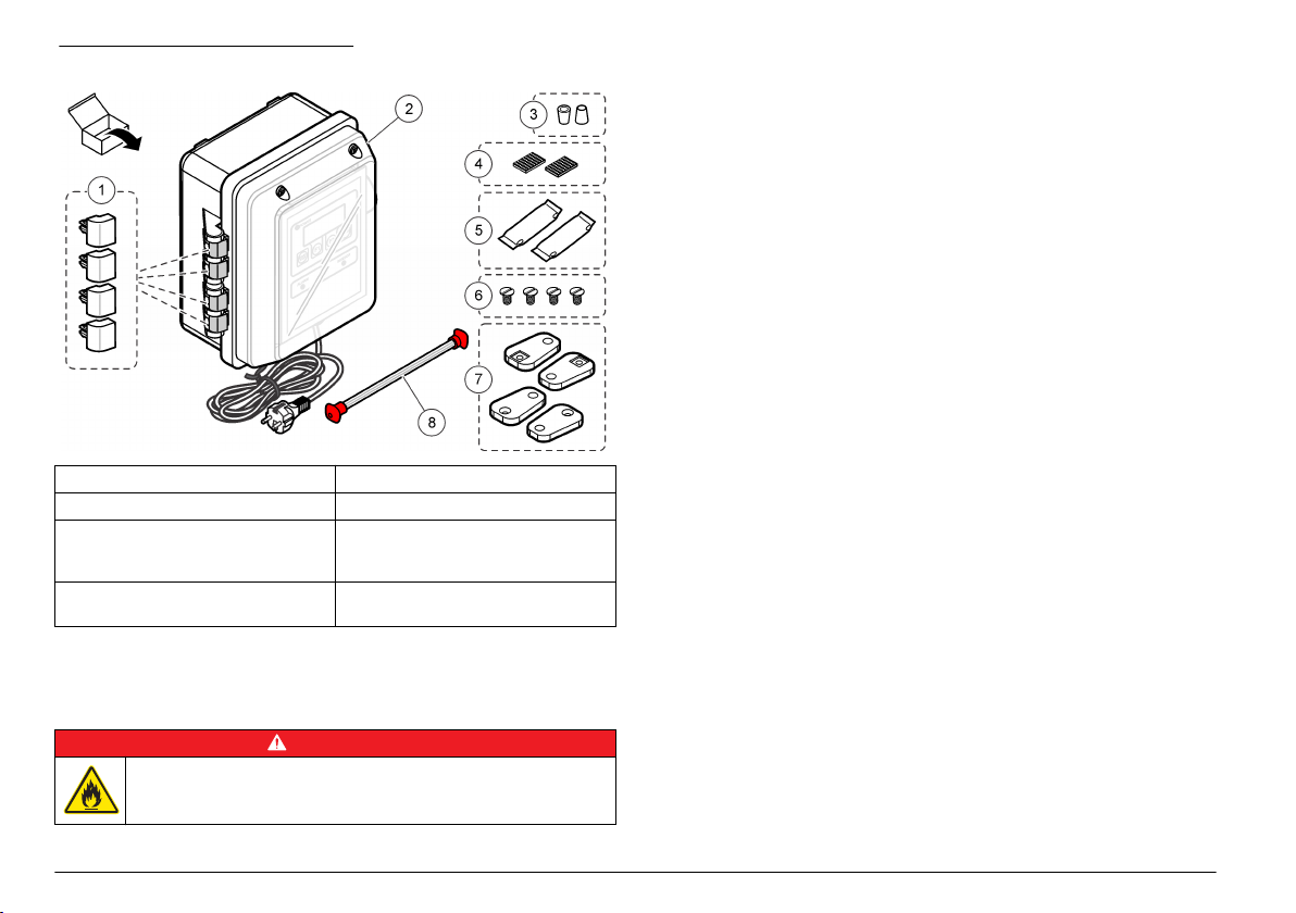
Abbildung 2 Produktkomponenten
1 Scharnierhalterung, Ersatzteile (4 x) 5 Trocknungsmittelpatronen (2 x)
2 WPC-21 oder WPC-22 6 Schrauben für Wandhalterung (4 x)
3 6-mm-Presshülsenadapter für
0,25 Zoll Klemmverschraubung
(2 x)
4 Klettband für
Trocknungsmittelpatronen (2 x)
7 Wandhalterungen (4 x)
8 Reinigungsbürstensatz mit zwei
Reinigungsbürsten
Installation
Installieren Sie das Messgerät:
• So nah wie möglich an der Probenquelle, um Verzögerungen bei der
Analyse zu verringern
•
An einem sauberen, trockenen, gut belüfteten, temperaturgeregelten,
vibrationsarmen Standort, der vor direkter Sonneneinstrahlung
geschützt ist
• Bei Installation im Freien in einem Gehäuse mit Schutz vor
Niederschlägen und direkter Sonneneinstrahlung, mit guter Belüftung
und Temperaturregelung
• An einem Standort, an dem der Netzschalter und das Netzkabel
sichtbar und leicht zugänglich sind
• An einem Standort, an dem ausreichend Spielraum vorhanden ist, um
die Leitungen zu verlegen und elektrischen Verbindungen
vorzunehmen
Mechanische Montage
Anbringen des Geräts an der Wand
Bringen Sie das Gerät aufrecht und waagerecht an einer ebenen,
vertikalen Fläche an. Beachten Sie dabei die in Abbildung 3
dargestellten Schritte. Das Befestigungsmaterial ist vom Benutzter zu
stellen.
Der Probenstrom muss stets entgegen der Schwerkraft erfolgen, um zu
verhindern, dass sich Blasen im Sensor ansammeln. Der Durchfluss
erfolgt in der Sensorbaugruppe von unten nach oben.
Hinweis: Dieses Gerät kann an eine vorhandene Schalttafel angebracht werden.
Befestigen Sie die Schrauben direkt an der Rückseite, oder verwenden Sie die
mitgelieferte Montagehardware.
Installationsanleitung
Brandgefahr. Dieses Produkt ist nicht für den Gebrauch mit
entzündbaren Flüssigkeiten geeignet.
24 Deutsch
G E F A H R
Page 25
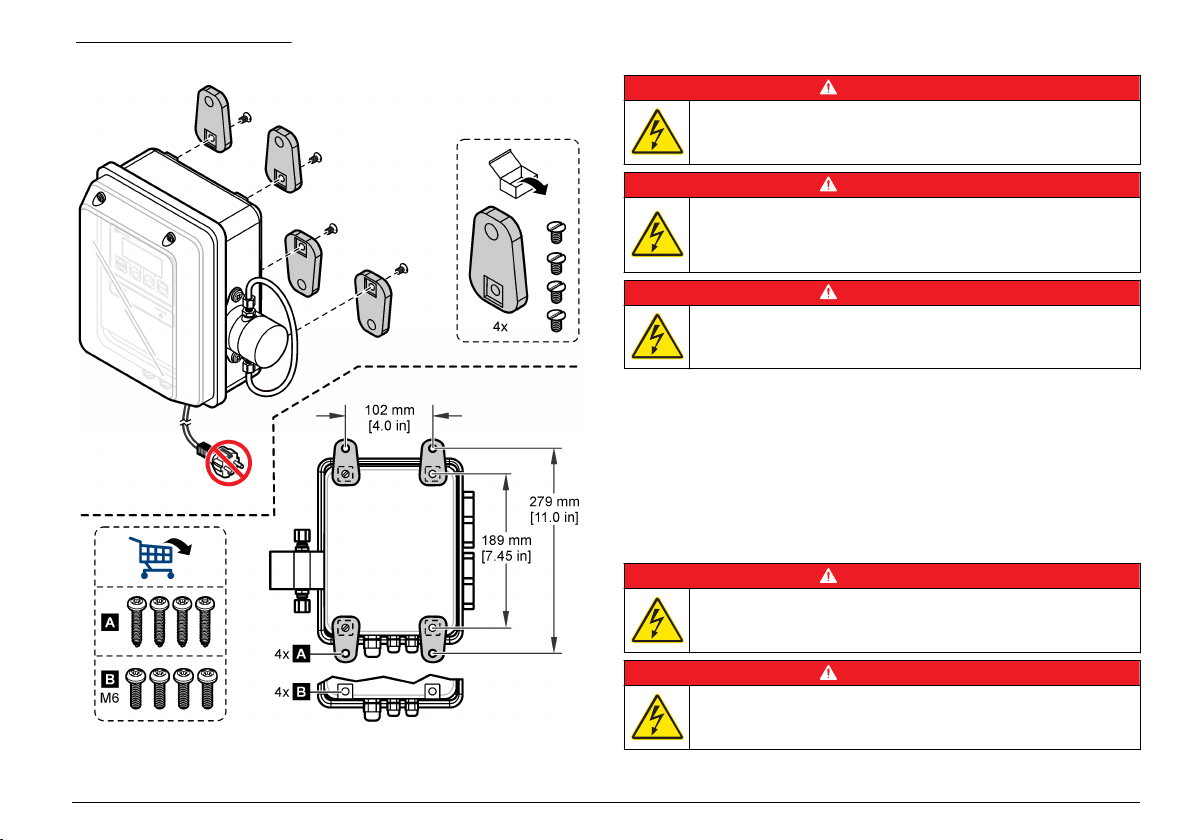
Abbildung 3 Wandmontage
Elektrische Installation
G E F A H R
Lebensgefahr durch Stromschlag. Trennen Sie das Gerät immer von
der Spannungsversorgung, bevor Sie elektrische Anschlüsse
herstellen.
Lebensgefahr durch Stromschlag. Wenn dieses Gerät im Freien oder
an potenziell feuchten Standorten eingesetzt wird, muss ein FISchutzschalter zum Anschluss an die Netzversorgung verwendet
werden.
Lebensgefahr durch Stromschlag. Es ist eine Schutzerdung
erforderlich.
Verwenden Sie für alle elektrischen Verbindungen, mit Ausnahme der
Eingangsleistung, abgeschirmte Zweidrahtleitungen. Die Verwendung
nicht abgeschirmter Kabel kann zu unzulässig hohen
Hochfrequenzemissionen oder Störempfindlichkeiten über das zulässige
Maß hinaus führen.
Zur Vermeidung von Stromschlägen durch Erdströme in unzureichenden
Erdungssystemen verbinden Sie die Abschirmung nur an der
Messgerätseite. Schließen Sie den Schirm nicht auf beiden Seiten an!
Elektrische Anschlüsse
Lebensgefahr durch Stromschlag. Verwenden Sie für die
Stromversorgung keinen Kabelkanal. Das Gehäuse verfügt über
keinen Schutzleiteranschluss (PET).
G E F A H R
G E F A H R
G E F A H R
G E F A H R
Lebensgefahr durch Stromschlag. Trennen Sie das Gerät immer von
der Spannungsversorgung, bevor Sie elektrische Anschlüsse
herstellen.
Deutsch 25
Page 26
In Abbildung 4 ist die Verkabelung und der allgemeine
Verdrahtungsvorgang dargestellt.
Verlegen Sie alle elektrischen Kabelverbindungen durch die
Kabelverschraubungen mit Zugentlastung. So bleibt die GehäuseSchutzart erhalten:
• Führen Sie nie mehr als ein Kabel (oder zwei Drähte) durch eine
Kabelverschraubung.
•
Vergewissern Sie sich, dass die nicht verwendeten
Kabelverschraubungen mit Gummikabelstecker verschlossen sind.
Verwenden Sie Kabelverschraubungen mit der entsprechenden
Schutzart.
Befolgen Sie alle Codes und Vorschriften für die Verkabelung. Ziehen
Sie die Kabelverschraubungen fest, um die Kabel zu sichern.
Abbildung 4 Verdrahtungsübersicht
26 Deutsch
1 Analoge Klemme mit
Stromausgängen und
Stromeingängen
2 Kommunikationsverbindungen
(RS232 und RS485)
3 Alarmkontakt (Digitalausgänge)
4 Kabelverschraubung mit
Zugentlastung (4 x)
Anschluss der Analogausgänge (optional)
Am J3-Anschluss stehen zwei 4-20-mA-Analogausgänge (AO1 und
AO2) zur Verfügung. Das Signal des Analogausgangs ist proportional zu
den Partikeln/ml des Kanals. Die Partikel/ml für Kanal 1 sind auf
AO1 dargestellt. Die Partikel/ml für Kanal 2 sind auf AO2 dargestellt.
Schließen Sie an jeden Analogausgang ein 24-28-AWG-Kabel an. Siehe
Tabelle 1.
Wenn die stromerhaltenden Geräte einen Lastwiderstand von 500 Ohm
oder mehr haben, legen Sie externe Spannung (maximal 40 VDC) an
Vext– und Vext+ des J1-Anschlusses an, um ausreichend Spannung für
das Gerät bereitzustellen.
Page 27
Tabelle 1 Anschlüsse des Analogausgangs (4-20 mA)
Pin Beschreibung
AO2– Ausgang AO2 -
AO2+ Ausgang AO2 +
AO1– Ausgang AO1 -
AO1+ Ausgang AO1 +
Anschluss des Analogeingangs (optional)
Am J3-Anschluss stehen zwei Analogeingänge (AI1 und AI2) zur
Verfügung. Schließen Sie Hilfsgeräte (z. B. Durchflussmessgeräte,
Trübungsmessgeräte, Druckmessumformer, pH-Messgeräte) an die
Analogeingänge an, um die von den Hilfsgeräten bereitgestellte
Spannung auf dem Gerätedisplay (0-10 VDC) anzuzeigen. Siehe
Identifikation der Werte des Analogeingangs auf Seite 34.
Schließen Sie an jeden Analogeingang ein Hilfsgerät an, und zwar mit
einem 22-24-AWG-Draht. Verwenden Sie einen 19-AWG-Draht, wenn
der Draht länger ist als 7,62 m. Siehe Tabelle 2.
Tabelle 2 Anschlüsse des Analogeingangs (0-10 VDC)
Pin Beschreibung
AI2– Eingang AI2 -
AI2+ Eingang AI2 +
AI1– Eingang AI1 -
AI1+ Eingang AI1 +
Anschluss des Digitaleingangs (optional)
Am J-Anschluss ist ein Digitaleingang verfügbar. Schließen Sie ein
Gerät zur Durchflussüberwachung an den Digitaleingang (CTS-Pin) an,
um einen Durchflussalarm auszulösen, wenn die Spannung am
Digitaleingang hoch oder niedrig ist, abhängig von der Statuseinstellung
des Durchflussalarms. Siehe Konfiguration des Partikelzählers
auf Seite 31, um die Statuseinstellung des Durchflussalarms zu
konfigurieren und den Durchflussalarm zu aktivieren.
Schließen Sie das Gerät für Durchflussüberwachung mit einem 24-28AWG-Draht an den CTS-Pin an.
Hinweis: Der Digitaleingang ist nicht verfügbar, wenn der RS232-Anschluss
verwendet wird, um einen Drucker oder Computer anzuschließen.
Anschluss der digitalen Ausgänge (optional)
Am J1-Anschluss stehen zwei Digitalausgänge (ALM und CAL) zur
Verfügung. Siehe Tabelle 3. Schließen Sie ein kompatibles Gerät, z. B.
eine Remote-Alarmanzeige oder einen Buzzer, mit einem 24-48-AWGDraht an den entsprechenden Digitalausgang an.
Der ALM-Pin und der CAL-Pin sind offene Kollektor-Ausgänge, die eine
Erdverbindung bereitstellen, wenn sie mit Strom versorgt werden.
Beachten Sie die Nennleistungen für den Digitalausgang in den
Technische Daten auf Seite 20.
Tabelle 3 Beschreibungen des Digitalausgangs
Digitaler Ausgang Beschreibung
ALM-Pin Wird mit Strom versorgt, wenn ein Durchflussalarm oder
CAL-Pin Wird mit Strom versorgt, wenn ein hoher oder niedriger
Zähleralarm aktiv ist. Siehe Konfiguration des
Partikelzählers auf Seite 31, um den Durchflussalarm und
den Zähleralarm zu konfigurieren.
Kalibrierungsfehler aktiv ist.
Anschluss eines seriellen Geräts (optional)
Am J4-Anschluss ist eine RS232-Verbindung verfügbar. Schließen Sie
einen Drucker oder den seriellen Anschluss eines Computers
(COM 1 oder COM 2) an den RS232-Anschluss an, um die gepufferten
Daten an einen Drucker oder Computer zu senden. Siehe Senden des
Datenspeichers an einen Drucker oder Computer auf Seite 33
Wenn der optionale RJ-45-zu-DB-9-Wandler verwendet wird, müssen
Sie ein RJ-45-Kabel aufschneiden, die einzelnen Adern aufspreizen und
identifizieren. Siehe Abbildung 5. Informationen zu den RS232Kabelanschlüssen finden Sie in Tabelle 4.
Hinweis: Der RS232-Anschluss ist nicht verfügbar, wenn der digitale Eingang
(CTS-Pin) verwendet wird.
.
Deutsch 27
Page 28
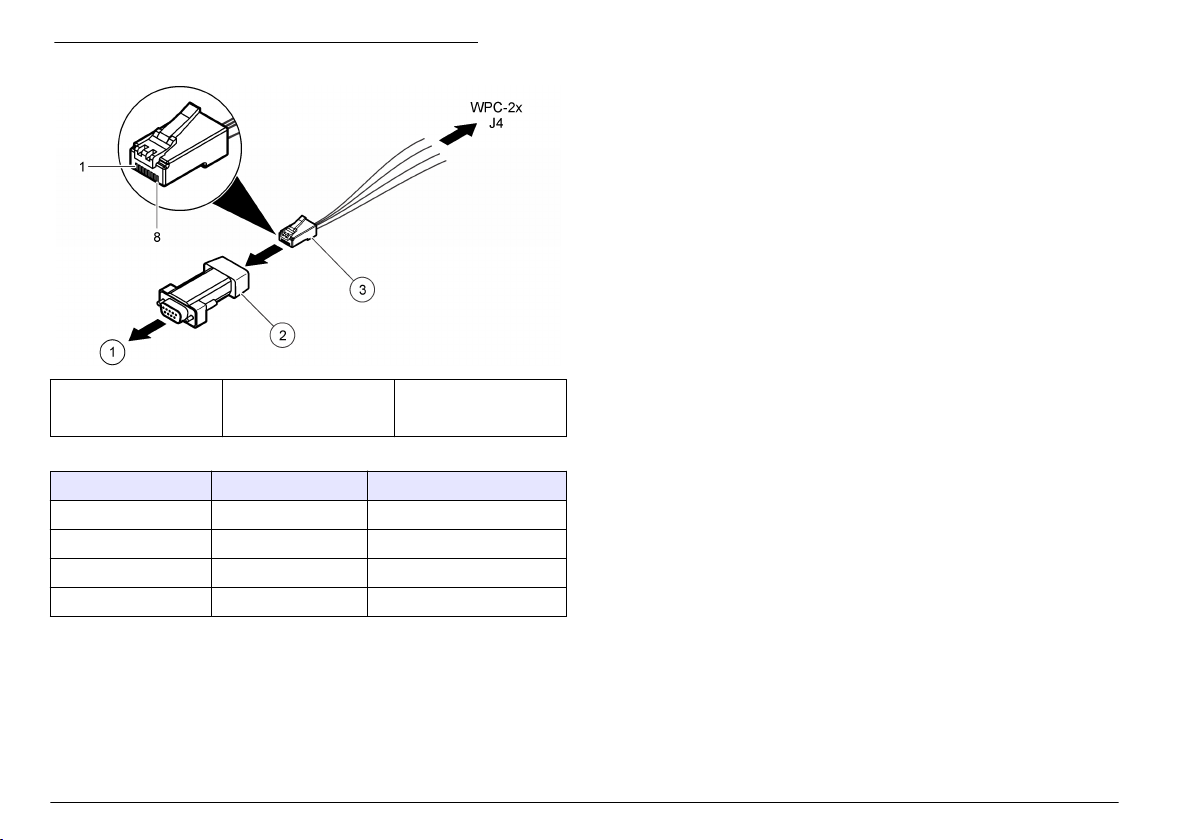
Abbildung 5 Verdrahtung des RJ-45-zu-DB-9-Wandlers
1 An PC oder Drucker 2 RJ-45-zu-DB-01-
Wandler
(SA000070-01)
3 RJ-45-Kabel (vom
Benutzer
bereitzustellen)
Tabelle 4 RS232-Verbindungen
DB-9-Pin RJ-45-Pin J4-Pin
Pin 2 RX Pin 3 TX
Pin 3 TX Pin 4 RX
Pin 4 DTR Pin 5 CTS
Pin 5 GND Pin 8 GND (Masse)
Stromversorgung zu externem Gerät (optional)
An JP1 sind +5 VDC oder +12 VDC verfügbar, um externe Geräte mit
Strom zu versorgen. +5 VDC wird angelegt, wenn die Brücke über den
+5V-Pin und Pin 2 von JP1 geht. +12 VDC wird angelegt, wenn die
Brücke über den Vps-Pin und Pin 2 von JP1 geht.
Hinweis: Der V+-Pin und der GND-Pin am J1-Anschluss werden nur für
Wartungszwecke verwendet.
Verbinden von Geräten in einem Netzwerk (optional)
In einem Netzwerk können mehrere Geräte miteinander verbunden
werden. Verwenden Sie den RS485-Anschluss der einzelnen Geräte
und ein geschirmtes 19-AWG-Kabel mit einem verdrillten Adernpaar, um
die Geräte mit einander zu verbinden.
Hinweise:
Es können maximal 32 Geräte in einem Netzwerk mit einem RS485-
•
Netzwerk verbunden werden.
•
Der Hostcomputer muss über Datenerfassungssoftware verfügen.
• Das Kommunikationsprotokoll ist Modbus. Beachten Sie die WPC
Modbus-Dokumentation auf der Website des Herstellers.
1. Am ersten Gerät:
a. Schieben Sie das ankommende Kabel vom RS232/RS485-
Wandler durch eine Kabelverschraubung mit Zugentlastung.
b. Schieben Sie das weiterführende Kabel durch eine
Kabelverschraubung.
c. Schließen Sie die ankommenden und weiterführenden Kabel an
den J4-Anschluss an. Siehe Tabelle 5.
2. Am zweiten Gerät:
a. Schieben Sie das ankommende Kabel vom ersten Gerät durch
eine Kabelverschraubung.
b. Schieben Sie das weiterführende Kabel durch eine
Kabelverschraubung.
c. Schließen Sie die ankommenden und weiterführenden Kabel an
den J4-Anschluss an. Siehe Tabelle 5.
3. Führen Sie Schritt 2 für das dritte und alle weiteren Geräte aus, bis
alle Geräte über ankommende und weiterführende Verbindungen
verfügen. Das letzte Gerät hat kein weiterführendes Kabel.
Hinweis: In einer Netzwerkinstallation ist das weiterführende Kabel vom
vorherigen Gerät stets das ankommende Kabel für das nächste Gerät.
4. Installieren Sie am letzten Gerät eine Brücke über JP2. Installieren
Sie an den anderen Geräten keine Brücke über JP2.
28 Deutsch
Page 29
5. Setzen Sie die Option MODE auf N (Netzwerkmodus). Siehe die
Option „Datum/MODUS“ in Konfiguration des Partikelzählers
auf Seite 31.
6. Weisen Sie jedem Gerät eine eindeutige Adresse zu. Siehe die
Option „Geräte-ID“ in Konfiguration des Partikelzählers
auf Seite 31.
Tabelle 5 RS485-Verbindungen
Kabel J4-Pin
– RS485 A
+ RS485 B
Schirm SGND
Montage der Schläuche
Schlauchanschlüsse
Zusätzlich erforderliche Artikel:
• Lichtundurchlässiger Schlauch, 6 mm Außendurchmesser
•
Zwei Presshülsen, 6 mm
Wählen Sie die Schläuche entsprechend den schlechtesten zu
erwartenden Umweltbedingungen (z. B. Temperaturbereich,
Sonneneinstrahlung, Luftverschmutzung) und dem höchst möglichen
Einlassdruck (maximal 120 psi) aus.
1. Entfernen Sie die Schläuche vom Anschluss der Probenleitung und
vom Anschluss der Ablaufleitung und werfen Sie sie weg.
Verwenden Sie die Schläuche für die Probenleitung oder die
Ablaufleitung nicht wieder.
2. Verbinden Sie eine Probenleitung mit dem Anschluss für die
Probenleitung am Gerätegehäuse. Siehe Abbildung 6.
3. Verbinden Sie eine Ablaufleitung mit dem Anschluss für die
Ablaufleitung am Gerätegehäuse. Siehe Abbildung 6.
4. Installieren Sie bei Bedarf einen Y-Schmutzfänger in der
Probenleitung, um zu verhindern, dass große Partikel in den Sensor
eindringen und dort Blockaden verursachen.
5. Installieren Sie ein manuelles Isolationsventil in der Probenleitung,
sodass der Durchfluss zum Gerät bei Bedarf gestoppt werden kann.
Abbildung 6 Installation des Schlauchanschlusses
1 Anschluss der Probenleitung 3 Kunststoffmutter
2 Anschluss der Ablaufleitung 4 Presshülse, 6 mm
Richtlinien für die Probenahme
Um beste Geräteleistung zu erzielen, wählen Sie einen guten,
repräsentativen Probenahmepunkt. Die Probe muss für das gesamte
System repräsentativ sein.
So vermeiden Sie fehlerhafte Messungen:
Entnehmen Sie Proben nur an Stellen, die sich in ausreichender
•
Entfernung zu Punkten befinden, an denen dem System chemische
Zusätze hinzugefügt werden.
•
Vergewissern Sie sich, dass die Proben ausreichend durchmischt
sind.
• Vergewissern Sie sich, dass alle chemischen Reaktionen
abgeschlossen sind.
Deutsch 29
Page 30
Anschließen des Probenstroms
Installieren Sie die Probenleitung in größeren Prozessleitungen, um
Störungen durch Luftblasen oder Ablagerungen am Boden der
Prozessleitung zu minimieren. Ideal ist eine Probenleitung, die direkt in
die Mitte der Prozessleitung führt.
Abbildung 7 zeigt gute und schlechte Beispiele für die Installation einer
Probenleitung in einer Prozessleitung.
Halten Sie die Probenleitung so kurz wie möglich, um Verzögerungen
bei der Analyse gering zu halten. In langen Probenleitungen können sich
am Boden Ablagerungen ansammeln.
Abbildung 7 Probenmethoden
1 Luft 2 Probenfluss
3. Stellen Sie den Netzschalter auf „Ein“.
4. Schließen Sie die Gehäusetür. Ziehen Sie alle vier gesicherten
Schrauben an, mit denen die Gehäusetür angebracht ist.
Benutzerschnittstelle und Navigation
Bedienung
In Abbildung 8 sind Display, Tastenfeld und LED-Anzeigelämpchen
dargestellt. Tastenbeschreibungen finden Sie in Tabelle 6.
Beschreibungen der LED-Anzeigelämpchen finden Sie in Tabelle 7.
Abbildung 8 Tastenfeld und Displayanzeige
Inbetriebnahme
Einschalten
1. Schließen Sie das Netzkabel an einen Stromanschluss mit Erdung
an.
2. Öffnen Sie die Gehäusetür. Lösen Sie alle vier gesicherten
Schrauben, mit denen die Gehäusetür angebracht ist.
30 Deutsch
1 Alarm-LED 5 Strom-LED
2 Taste F1 6 ENTER-Taste
3 START/STOPP-Taste 7 Taste F2
4 Display 8 Sensor-LED
Page 31

Tabelle 6 Tastenbeschreibungen
Taste Beschreibung
START/STOPP Startet oder stoppt die Partikelzählung
F1 Zum Navigieren durch die Menüs und Ändern der
Einstellungen
F2 Zum Navigieren durch die Menüs und Ändern der
Einstellungen
ENTER Bestätigen, eingeben oder auswählen. Drücken, um die
aktuelle Zahl im Puffer zu speichern (nur eigenständiger
Modus).
Tabelle 7 Beschreibung der LED-Anzeigelämpchen
LED Farbe Beschreibung
Power Grün Das Gerät wird mit Strom versorgt, und der Netzschalter ist
eingeschaltet.
Alarm Rot Leuchtet durchgehend: Ein Netzwerkalarm ist aktiv.
Blinkt: Ein Zähleralarm oder ein Durchflussalarm ist aktiv.
Siehe Fehlerbehebung auf Seite 37.
Sensor Gelb Leuchtet durchgehend: Ein hoher Kalibrierungsfehler ist aktiv.
Blinkt: Ein niedriger Kalibrierungsfehler ist aktiv.
Siehe Fehlerbehebung auf Seite 37.
Displaybeschreibung
In Abbildung 9 sind die auf dem Display angezeigten Informationen
dargestellt
Wenn ein Kalibrierungsfehler oder ein Durchflussalarm auftritt, wird auf
dem Display eine Fehlermeldung angezeigt. Siehe Fehlermeldungen
auf Seite 38.
Abbildung 9 Tastenfeld und Displayanzeige
1 Auf Kanal 2 überwachte
Partikelgröße
2 Auf Kanal 1 überwachte
Partikelgröße
3 Partikelzahl auf Kanal 1
4 Partikelzahl auf Kanal 2
5 Funktionen der Softkeys F1 und F2
Betrieb
Konfiguration des Partikelzählers
Der Partikelzähler kann für eigenständigen oder Netzwerkbetrieb
konfiguriert werden. Im Netzwerkmodus werden die Einstellungen für
Datenpufferung, Drucken und Kanal-2-Größe mithilfe der
Netzwerksoftware geändert, sodass diese Einstellungen auf dem
Gerätedisplay nicht verfügbar sind.
1. Drücken Sie F1, um eine Option auszuwählen, und dann ENTER.
Die aktuellen Einstellungen werden angezeigt.
Deutsch 31
Page 32

Nur eigenständiger Modus
Optionen Beschreibung
Intervals BUF: Festlegen des Pufferintervalls
(Datenspeicher). Optionen: OFF (deaktiviert),
30 Sekunden, 1, 5, 10, 30 oder 60 Minuten.
Am Ende jedes Pufferintervalls werden Datum,
Uhrzeit, Sensorstatus und Zählung im Puffer
gespeichert. Der Puffer speichert maximal
100 Datensätze. Wenn der Puffer voll ist, werden
die ältesten Daten mit den neuen Daten
überschrieben.
Hinweis: Wenn ein serieller Drucker angeschlossen ist,
werden die Daten jedes Mal, wenn sie im Puffer
gespeichert werden, auch an den Drucker gesendet.
SCRL: Festlegen des Blätterintervalls. Optionen:
OFF (deaktiviert), 30 Sekunden, 1, 5, 10, 30 oder
60 Minuten.
Am Ende jedes Blätterintervalls beginnt das Gerät,
die nächste kalibrierte Partikelgröße auf Kanal 2 zu
überwachen. Falls diese Funktion deaktiviert ist,
entspricht die auf Kanal 2 überwachte
Partikelgröße der Größeneinstellung für Kanal 2.
Hinweis: Es werden keine Daten im Puffer gespeichert,
wenn das Pufferintervall länger ist als das Blätterintervall.
Buff Count/Print
Buff/Download
(Pufferzähler/Puffer
drucken/Download)
Siehe Senden des Datenspeichers an einen
Drucker oder Computer auf Seite 33. Der
angezeigte Pufferzählerwert entspricht der Anzahl
der Einträge im Puffer (Datenspeicher).
Optionen Beschreibung
Buff Count/View
Buffer/Delete Buffer
(Pufferzähler/Puffer
anzeigen/Puffer
Siehe Anzeigen oder Löschen des Puffers
(Datenspeicher) auf Seite 34. Der angezeigte
Pufferzählerwert entspricht der Anzahl der Einträge
im Puffer (Datenspeicher).
löschen)
Count Alarms
(Zählalarme)
Legen Sie die Mindestanzahl der Partikel fest, die
einen Zählalarm auf Kanal 1 und Kanal 2 auslösen.
Stellen Sie 0 ein, um diese Funktion zu
deaktivieren.
A1: Zählergrenzwert für Kanal 1
A2: Zählergrenzwert für Kanal 2
Drücken Sie INC, um die gewählte Ziffer zu
ändern. Drücken Sie die Pfeiltaste nach RECHTS,
um die nächste Ziffer auszuwählen.
Nur Netzwerkmodus
Optionen Beschreibung
Geräte-ID = 1 Legen Sie eine eindeutige Adresse für das Gerät fest.
Optionen: 1 bis 247. Adresse 0 kann nicht verwendet
werden. Diese Option wird nur angezeigt, wenn die Option
MODE auf N (Netzwerkmodus) gesetzt ist.
32 Deutsch
Page 33

Eigenständiger Modus und Netzwerkmodus
Optionen Beschreibung
Analoger
Zählerausgang/Oberer 1/Unterer 1
Analoger
Zählerausgang/Oberer 2/Unterer 2
Kanal 2, Größe Drücken Sie die Pfeiltasten nach
Durchflussrate/Durchflussalarm RATE: Eingabe der Durchflussrate.
Legen Sie die Zählergrenzwerte (den
Bereich) für den analogen Ausgang
(4-20 mA) für Kanal 1 fest.
UL1: Oberer Zählergrenzwert, der
einem 20-mA-Ausgangssignal
entspricht.
LL1: Unterer Zählergrenzwert, der
einem 4-mA-Ausgangssignal
entspricht.
Legen Sie die Zählergrenzwerte (den
Bereich) für den analogen Ausgang
(4-20 mA) für Kanal 2 fest.
UL2: Oberer Zählergrenzwert, der
einem 20-mA-Ausgangssignal
entspricht.
LL2: Unterer Zählergrenzwert, der
einem 4-mA-Ausgangssignal
entspricht.
OBEN und UNTEN, um die
Partikelgröße festzulegen, die auf
Kanal 2 überwacht wird, wenn das
Blätterintervall auf OFF gesetzt ist.
ALM: Aktivieren (ON) oder
Deaktivieren (OFF) des
Durchflussalarms. Wenn ein Gerät
zur Durchflussüberwachung zur
Verfügung steht, wird der
Durchflussalarm am digitalen
Eingang (CTS-Pin) überwacht.
Optionen Beschreibung
Status Durchflussalarm aktiv Stellen Sie den Durchflussalarm so
ein, dass er bei einem hohen oder
niedrigen Spannungseingang am
CTS-Pin ausgelöst wird, abhängig
vom Aktivierungsstatus des
Durchflussalarmgeräts. Optionen: HI
oder LO.
Wenn die Option „Status
Durchflussalarm aktiv“ auf HI gesetzt
ist, löst der Eingang hoher Spannung
(> 2,5 VDC) am CTS-Pin des
Durchflussüberwachungsgeräts
einen Durchflussalarm aus; 0 V steht
für einen normalen Durchfluss.
Eingang 1/Eingang 2 Siehe Identifikation der Werte des
Analogeingangs auf Seite 34.
Kontrast/Piepton CON: Anpassen des Kontrasts.
BEP: Aktivieren (ON) oder
Deaktivieren (OFF) des hörbaren
Pieptons.
Datum/MODUS Date: Eingabe des Datums und der
Uhrzeit (24-Stunden-Format).
MODE: Wahl des Modus. Optionen:
S (eigenständiger Modus) oder N
(Netzwerkmodus)
Senden des Datenspeichers an einen Drucker oder Computer
Die Daten im Puffer (Datenspeicher) können an einen angeschlossenen
Drucker oder Computer gesendet werden. Siehe Anschluss eines
seriellen Geräts (optional) auf Seite 27.
1. Stellen Sie für den seriellen Anschluss des Druckers und/oder
Computers 9600 Baud, 8 Daten, keine Parität, 1 Stoppbit und keine
Ablaufsteuerung ein.
Hinweis: Der Computer oder Drucker wird keine vollständigen Übertragungen
erhalten, wenn das Gerät nicht durchgängig mit 9600 Baud empfangen kann.
Deutsch 33
Page 34

2. Drücken Sie F1, bis „Buff Count/Print Buff/Download“
(Pufferzähler/Puffer drucken/Download) angezeigt wird, und
anschließend ENTER.
3. Wählen Sie eine Option aus. Drücken Sie zum Beenden ENTER.
Optionen Beschreibung
PRT Sendet die Daten im Puffer (Datenspeicher) an den
angeschlossenen Drucker oder das Terminaldisplay. Die ältesten
Daten werden zuerst gesendet. Die Sensorstatuscodes finden
Sie in Tabelle 11.
DNLD Sendet die Daten im Puffer (Datenspeicher) an den
angeschlossenen Computer. Die Sensorstatuscodes finden Sie
in Tabelle 11.
Tabelle 11 Statuscodes (binär)
Code Beschreibung
1 Sensorfehler
2 CH1-Zähleralarm
3 Sensorfehler und CH1-Zähleralarm
4 CH2-Zähleralarm
5 Sensorfehler und CH2-Zähleralarm
6 CH1- und CH2-Zähleralarme
7 Sensorfehler, CH1-Zähleralarm und CH2-Zähleralarm
8 Durchflussalarm oder Digitaleingangsalarm
Anzeigen oder Löschen des Puffers (Datenspeicher)
1. Drücken Sie F1, bis „Buff Count/View Buffer/Delete Buffer“
(Pufferzähler/Puffer anzeigen/Puffer löschen) angezeigt wird, und
anschließend ENTER.
2. Wählen Sie eine Option aus. Drücken Sie zum Beenden ENTER.
Optionen Beschreibung
VIEW
(ANSICHT)
DEL Löscht alle Daten im Puffer (Datenspeicher). Drücken Sie
Zeigt die Daten im Puffer (Datenspeicher) an. Die aktuellen
Daten werden zuerst angezeigt. Folgende Statuscodes
werden angezeigt:
A: Einer der Kanäle lag über der Zähleralarmeinstellung für
den Kanal.
S: Eventuell muss die Sensor-Durchflusszelle gereinigt
werden.
Drücken Sie auf BAK, um zurückzukehren. Drücken Sie
NXT, um vorwärts zu blättern. Drücken Sie zum Beenden
ENTER.
zum Bestätigen YES (Ja) oder zum Abbrechen NO (Nein).
Identifikation der Werte des Analogeingangs
Drücken Sie F1, bis „Input 1/Input 2“ angezeigt wird, und anschließend
ENTER. Die vom dem an den einzelnen Analogeingängen
angeschlossenem Hilfsgerät bereitgestellte Spannung wird angezeigt.
Diese Informationen werden im eigenständigen Modus nicht gepuffert,
können aber im Netzwerkmodus abgerufen werden.
Kalibrierung
Das Messgerät kann nicht vom Benutzer kalibriert werden. Wenden Sie
sich zum Kalibrieren des Messgerät an den Hersteller. Angaben zur
fälligen Kalibrierung finden Sie auf dem Aufkleber am Gerät.
Wartung
W A R N U N G
Mehrere Gefahren. Nur qualifiziertes Personal sollte die in diesem
Kapitel des Dokuments beschriebenen Aufgaben durchführen.
34 Deutsch
Page 35

Wartungsplan
In Tabelle 12 ist der empfohlene Wartungsplan dargestellt. Je nach
Anforderungen der Anlage und den Betriebsbedingungen kann es
erforderlich sein, einige Aufgaben häufiger auszuführen.
Tabelle 12 Wartungsplan
Maßnahme 1 Jahr Wie erforderlich
Kalibrierung auf Seite 34 X
Seite 35 X
Reinigung der Sensor-Durchflusszelle auf Seite 35 X
Austauschen der Trocknungsmittelpatrone
auf Seite 36
Austauschen einer Sicherung auf Seite 36 X
1
Erforderlich, um JIS B 9925-1997-Standards zu erfüllen
1
X
Reinigung der Sensor-Durchflusszelle
H I N W E I S
Führen Sie die Reinigungsbürste nicht in den Anschluss der Probenleitung ein,
wenn die Sensor-Durchflusszelle trocken ist, da sie sonst beschädigt werden
kann.
Reinigen Sie die Sensor-Durchflusszelle regelmäßig. Reinigen Sie
darüber hinaus die Sensor-Durchflusszelle vor der Verwendung, wenn
das Gerät über einen längeren Zeitraum nicht verwendet wurde.
Zusätzlich erforderliche Artikel:
• Werkseitig mitgelieferte Reinigungsbürste
•
Sauberes Wasser
2. Stellen Sie den Netzschalter auf „Aus“.
3. Stoppen Sie den Wasserfluss zum Gerät.
4. Trennen Sie die Probenleitung und die Ablaufleitung von den
Klemmringverschraubungen.
5. Verbinden Sie die Probenleitung mit der Klemmringverschraubung
oben an der Sensorbaugruppe.
6. Starten Sie den Wasserfluss zum Gerät. Stoppen Sie den Fluss nach
30 Sekunden.
7. Entfernen Sie die Probenleitung von der Klemmringverschraubung.
8. Reinigen Sie die Sensor-Durchflusszelle.
a. Füllen Sie sauberes Wasser in die Klemmringverschraubung
oben an der Sensorbaugruppe. Das Wasser läuft aus der
Klemmringverschraubung der Probenleitung ab.
b. Führen Sie die Reinigungsbürste in die Klemmringverschraubung
ein. Bewegen Sie die Bürste zwei- oder dreimal vorsichtig nach
oben und unten. Siehe Abbildung 10.
c. Füllen Sie sauberes Wasser in die Klemmringverschraubung
oben an der Sensorbaugruppe. Dadurch werden alle Materialien,
die mit der Bürste gelöst wurden, ausgespült.
d. Gießen Sie sauberes Wasser über die Reinigungsbürste, um
zurückgebliebene Materialien abzuspülen.
9. Verbinden Sie die Schläuche der Probenleitung und Abflussleitung.
Siehe Schlauchanschlüsse auf Seite 29.
10. Starten Sie den Wasserfluss zum Gerät.
11. Stellen Sie den Netzschalter auf „Ein“.
12. Schließen Sie die Gehäusetür. Ziehen Sie alle vier gesicherten
Schrauben fest, mit denen die Gehäusetür angebracht ist.
1. Öffnen Sie die Gehäusetür. Lösen Sie alle vier gesicherten
Schrauben, mit denen die Gehäusetür befestigt ist.
Deutsch 35
Page 36

Abbildung 10 Reinigen der Sensor-Durchflusszelle
Austauschen der Trocknungsmittelpatrone
Tauschen Sie die Trocknungsmittelpatrone aus, wenn die Farbe der
Kristalle in der Trocknungsmittelpatrone von blau zu rosa wechselt. Die
Lage der Trocknungsmittelpatrone finden Sie in Abbildung 1
auf Seite 23.
Eine Trocknungsmittelpatrone muss verwendet werden, damit sich keine
Feuchtigkeit im Gerätegehäuse ansammelt. Dadurch werden die
Korrosion empfindlicher elektrischer Verbindungen und die Ansammlung
von Kondensation in der Sensorbaugruppe verhindert.
Zusätzlich erforderliche Artikel:
• Trocknungsmittelpatrone
Klettband
•
1. Öffnen Sie die Gehäusetür. Lösen Sie alle vier gesicherten
Schrauben, mit denen die Gehäusetür angebracht ist.
2. Stellen Sie den Netzschalter auf „Aus“.
3. Öffnen Sie die elektrische Schalttafel. Drehen Sie die beiden
gesicherten Vierteldrehungs-Schrauben nur eine Vierteldrehung.
4. Tauschen Sie die Trocknungsmittelpatrone aus.
a. Ziehen Sie die gebrauchte Trocknungsmittelpatrone vom
Klettband an der Rückseite, und entsorgen Sie sie.
b. Kleben Sie ein neues Klettband an eine neue
Trocknungsmittelpatrone.
c. Drücken Sie die Trocknungsmittelpatrone an das Klettband an
der Rückseite.
5. Schließen Sie die elektrische Schalttafel, und sichern Sie sie mit den
beiden Vierteldrehungs-Schrauben.
6. Stellen Sie den Netzschalter auf „Ein“.
7. Schließen Sie die Gehäusetür. Ziehen Sie alle vier gesicherten
Schrauben an, mit denen die Gehäusetür angebracht ist.
Austauschen einer Sicherung
G E F A H R
Brandgefahr. Ersetzen Sie Sicherungen mit dem gleichem Typ und
Nennstrom.
G E F A H R
Lebensgefahr durch Stromschlag. Trennen Sie jegliche Stromzufuhr
von dem Instrument und den Relaisverbindungen, bevor Sie mit dieser
Wartungsaufgabe beginnen.
Zusätzlich erforderliche Artikel:
• Sicherung, 5 x 20 mm T, 0,500 mA, 250 V
•
Kreuzschlitz-Schraubendreher
1. Öffnen Sie die Gehäusetür. Lösen Sie alle vier gesicherten
Schrauben, mit denen die Gehäusetür angebracht ist.
2. Stellen Sie den Netzschalter auf „Aus“.
3. Öffnen Sie die elektrische Schalttafel. Drehen Sie die beiden
gesicherten Vierteldrehungs-Schrauben nur eine Vierteldrehung.
4. Tauschen Sie die Sicherung aus. Beachten Sie dabei die in
Abbildung 11 dargestellten Schritte.
36 Deutsch
Page 37

5. Bauen Sie das Gerät zusammen. Gehen Sie in umgekehrter
Reihenfolge nach den bebilderten Schritten in Abbildung 11 vor.
6. Schließen Sie die elektrische Schalttafel, und sichern Sie sie mit den
beiden Vierteldrehungs-Schrauben.
7. Stellen Sie den Netzschalter auf „Ein“.
8. Schließen Sie die Gehäusetür. Ziehen Sie alle vier gesicherten
Schrauben an, mit denen die Gehäusetür angebracht ist.
Abbildung 11 Austauschen einer Sicherung
Fehlerbehebung
Problem Mögliche Ursache Lösung
Strom-LED leuchtet
nicht
ALARM-LED leuchtet Ein Netzwerkalarm ist
ALARM-LED blinkt Ein Zähleralarm (nur
SENSOR-LED leuchtet Ein hoher
Das Gerät wird nicht mit
Strom versorgt, oder der
Netzschalter ist auf „Aus“
geschaltet.
aktiv.
Hinweis: Ein Netzwerkalarm
kann nur über die
Netzwerksoftware aktiviert
oder deaktiviert werden.
eigenständiges Gerät)
oder ein Durchflussalarm
ist aktiv.
Hinweis: Wenn ein
Zähleralarm aktiv ist, blinken
die ALARM-LED und der
Kanal mit dem Alarm auf dem
Display.
Kalibrierungsfehler ist
aktiv. Der Sensor ist
verunreinigt, oder die
Laserdiode verliert an
Leistung.
Vergewissern Sie sich,
dass der Netzschalter auf
„Ein“ geschaltet ist. Stellen
Sie sicher, dass das Gerät
mit Strom versorgt ist.
—
Informationen zum
Konfigurieren der
Zähleralarmeinstellungen
finden Sie in Konfiguration
des Partikelzählers
auf Seite 31.
Reinigen Sie die
Durchflusszelle. Siehe
Reinigung der SensorDurchflusszelle
auf Seite 35.
Wenn der hohe
Kalibrierungsfehler
weiterhin auftritt, wenden
Sie sich an den
technischen Support.
Deutsch 37
Page 38

Problem Mögliche Ursache Lösung
SENSOR-LED blinkt Ein niedriger
Zwei oder mehr Geräte
reagieren nicht auf die
Überwachungssoftware.
Kalibrierungsfehler ist
aktiv. Die Fotodiode ist
gesättigt und sollte
gereinigt, angepasst oder
ersetzt werden.
Zwei oder mehr Geräte
haben dieselbe Adresse.
Geräte mit derselben
Adresse reagieren nicht
auf die
Überwachungssoftware.
Reinigen Sie die
Durchflusszelle. Siehe
Reinigung der SensorDurchflusszelle
auf Seite 35.
Wenn der niedrige
Kalibrierungsfehler
weiterhin auftritt, wenden
Sie sich an den
technischen Support.
Schalten Sie die
Überwachungssoftware
aus, und weisen Sie den
Geräten mit derselben
Adresse eine eindeutige
Adresse zu. Siehe die
Option „Geräte-ID“ in
Konfiguration des
Partikelzählers
auf Seite 31.
Fehlermeldungen
Meldung Mögliche Ursache Lösung
CAL Ein hoher oder niedriger
Kalibrierungsfehler ist aktiv.
FLOW Das externe Gerät zur
Durchflussüberwachung hat
einen Durchflussalarm ausgelöst.
Reinigen Sie die Durchflusszelle.
Siehe Reinigung der Sensor-
Durchflusszelle auf Seite 35.
Wenn der Kalibrierungsfehler
weiterhin auftritt, wenden Sie sich
an den technischen Support.
Siehe Anschluss des
Digitaleingangs (optional)
auf Seite 27.
Ersatzteile und Zubehör
W A R N U N G
Verletzungsgefahr. Die Verwendung nicht zugelassener Teile kann zur
Verletzung von Personen, zu Schäden am Messgerät oder zu
Fehlfunktionen der Ausrüstung führen. Die Ersatzteile in diesem
Abschnitt sind vom Hersteller zugelassen.
Hinweis: Produkt- und Artikelnummern können für einige Verkaufsgebiete
abweichen. Wenden Sie sich an den zuständigen Distributor oder schlagen Sie die
Kontaktinformationen auf der Webseite des Unternehmens nach.
Ersatzteile
Beschreibung Bestellnr.
Presshülse, 6 mm, Adapter für 0,25 Zoll
Klemmverschraubung
Reinigungsbürstensatz mit zwei 1-µm-Bürsten, für
WPC-22
Reinigungsbürstensatz mit zwei 2-µm-Bürsten, für
WPC-21
Trocknungsmittelsatz mit zwei Trocknungsmittelpatronen
und zwei Klettstreifen
Sicherung, 5 x 20 mm T, 0,500 mA, 250 V 500-150-0050
Netzkabel, 230 V AC 510667
Kabelverschraubung für Netzkabel VP752401
Kabelverschraubung für externe Verbindungen 570-730-2212
Zubehör
Beschreibung Bestellnr.
MP000147-01
SA000120-02
SA000120-01
SA000180-01
38 Deutsch
AQUARIUS-Software CS200011
RJ-45-zu-DB-9-Wandler SA000070-01
RS485/RS422-zu-USB-Wandler 5920400
Page 39

Zubehör (fortgesetzt)
Beschreibung Bestellnr.
Schlauch, lichtundurchlässig, 0,25 Zoll
Außendurchmesser, schwarzes PTFE
Mengenregler für Durchflussanpassung 2081335-1
VP792021
Deutsch 39
Page 40

Dati tecnici
I dati tecnici sono soggetti a modifica senza preavviso.
Dato tecnico Dettagli
Dimensioni (L x P x A) 248 x 114 x 302 mm (9,75 x 4,50 x 11,88 pollici) con
sensore e staffe di montaggio
Struttura NEMA 4X
Sorgente luminosa Diodo laser classe 3B, 780 nm, 5 mW; vita utile di
30.000 ore
Rilevatore Fotodiodo
Display LCD, 4 righe x 16 caratteri
Dimensioni delle porte Due raccordi a compressione per tubi di ingresso e
uscita con diametro esterno 0,25 pollici
Materiali umidi Vetro di silice, Viton (fluorocarburo) e Kynar (PVDF)
Cella a flusso WPC-21: 600 x 600 µm in vetro di silice con
rivestimenti AR
WPC-22: 800 x 800 µm in vetro di silice con
rivestimenti AR
Peso 2,25 kg (5 lb)
Categoria di installazione II
Classe di protezione I
Grado di inquinamento 2
Condizioni di esercizio WPC-21: da 5 a 40 °C (da 41 a 104 °F), dal 5 al
90% di umidità relativa, senza condensa
WPC-22: da 5 a 45 °C (da 41 a 113 °F), dal 5 al
90% di umidità relativa, senza condensa
Condizioni di stoccaggio Da –20 a 60 °C (da –4 a 140 °F), 98% di umidità
relativa, senza condensa (massimo)
Altitudine 2000 m (6562 piedi) massimo
Requisiti di alimentazione 230 VCA ±15% , 20 VA, 50/60 Hz
Dato tecnico Dettagli
Metodo di rilevamento Oscuramento della luce
Calibrazione WPC-21: calibrazione in fabbrica a una portata di
Dimensioni di particelle WPC-21: 1,3, 2, 3, 5, 7, 10, 15 e 25 µm
Campi di coincidenza WPC-21: perdita del 10% a 25.000 particelle/mL
Numero di canali Due canali; Canale 1: dimensioni particelle più
Unità di misura Numero di particelle per mL
Risoluzione del sensore Meno del 10% a 10 µm come descritto in ASTM-
Efficienza di conteggio del
sensore
Pressione dei campioni 8,3 bar (120 psi) massimo
Portata dei campioni WPC-21: 45–55 mL/minuto
Temperatura dei campioni Da 0 a 50 °C (da 32 a 122 °F), senza congelamento
Ingresso digitale Uno; 0–10 VCC, ± 24 VCC < 10 mA
Uscite digitali Due; a collettore aperto (100 mA, 24 VCC massimo)
Ingressi analogici Due; 0–10 VCC
Uscite analogiche 2 canali: 4–20 mA
50 mL/minuto, tracciabilità NIST, otto dimensioni di
particelle
WPC-22: calibrazione in fabbrica a una portata di
100 mL/minuto, tracciabilità NIST, otto dimensioni di
particelle
WPC-22: 2, 5, 7, 10, 15, 25, 50 e 100 µm
WPC-22: perdita del 10% a 15.000 particelle/mL
piccole, Canale 2: una delle altre sette dimensioni di
particelle (fissa) o tutte e sette le dimensioni
(scorrimento)
F658-87
Conforme agli standard JIS 9925 B-1997
WPC-22: 90–110 mL/minuto
40 Italiano
Page 41

Dato tecnico Dettagli
Comunicazioni RS485 (protocollo: MODBUS) o RS232, doppino
Memoria dati 100 misure
Certificazioni CE (Direttiva Bassa Tensione)
intrecciato schermato da 19 AWG
Informazioni generali
In nessun caso, il produttore potrà essere ritenuto responsabile in caso
di danni diretti, indiretti, particolari, causali o consequenziali per qualsiasi
difetto o omissione relativa al presente manuale. Il produttore si riserva il
diritto di apportare eventuali modifiche al presente manuale e ai prodotti
ivi descritti in qualsiasi momento senza alcuna notifica o obbligo. Le
edizioni riviste sono presenti nel sito Web del produttore.
Informazioni sulla sicurezza
A V V I S O
Il produttore non sarà da ritenersi responsabile in caso di danni causati
dall'applicazione errata o dall'uso errato di questo prodotto inclusi, a puro titolo
esemplificativo e non limitativo, i danni incidentali e consequenziali; inoltre
declina qualsiasi responsabilità per tali danni entro i limiti previsti dalle leggi
vigenti. La responsabilità relativa all'identificazione dei rischi critici
dell'applicazione e all'installazione di meccanismi appropriati per proteggere le
attività in caso di eventuale malfunzionamento dell'apparecchiatura compete
unicamente all'utilizzatore.
Prima di disimballare, installare o utilizzare l’apparecchio, si prega di
leggere l’intero manuale. Si raccomanda di leggere con attenzione e
rispettare le istruzioni riguardanti possibili pericoli o note cautelative. La
non osservanza di tali indicazioni potrebbe comportare lesioni gravi
dell'operatore o danni all'apparecchio.
Assicurarsi che la protezione fornita da questa apparecchiatura non sia
danneggiata. Non utilizzare o installare questa apparecchiatura in modo
diverso da quanto specificato nel presente manuale.
Utilizzo dei segnali di pericolo
P E R I C O L O
Indica una situazione di pericolo potenziale o imminente che, se non evitata,
potrebbe causare lesioni gravi o la morte.
A V V E R T E N Z A
Indica una situazione di pericolo potenziale o imminente che, se non evitata,
potrebbe comportare lesioni gravi, anche mortali.
A T T E N Z I O N E
Indica una situazione di pericolo potenziale che potrebbe comportare lesioni lievi
o moderate.
Indica una situazione che, se non evitata, può danneggiare lo strumento.
Informazioni che richiedono particolare attenzione da parte dell'utente.
A V V I S O
Etichette di avvertimento
Leggere tutte le etichette presenti sullo strumento. La mancata
osservanza delle stesse può causare lesioni personali o danni allo
strumento. A ogni simbolo riportato sullo strumento corrisponde
un'indicazione di pericolo o di avvertenza nel manuale.
Se presente sullo strumento, questo simbolo rinvia alle informazioni
sul funzionamento e/o sulla sicurezza contenute nel manuale per
l'utente.
Tale simbolo potrebbe essere applicato alla struttura esterna o a un
dispositivo di protezione del prodotto e indica un rischio dovuto a
scossa elettrica e/o la possibilità di folgorazione.
Componenti elettronici interni delicati possono essere danneggiati
dall'elettricità statica, compromettendo le prestazioni o provocando
guasti.
Questo simbolo indica che nell'apparecchiatura è utilizzato un
dispositivo laser.
Italiano 41
Page 42

Questo simbolo identifica la posizione di un fusibile o di un dispositivo
di limitazione della corrente.
Apparecchiature elettriche con apposto questo simbolo non possono
essere smaltite in impianti di smaltimento pubblici europei dopo il
12 agosto 2005. In conformità ai regolamenti europei locali e
nazionali (a norma della direttiva UE 2002/96/CE), gli utenti dovranno
restituire le apparecchiature vecchie o non più utilizzabili al
produttore, il quale è tenuto a provvedere allo smaltimento gratuito.
Nota: Per la restituzione al fine del riciclaggio, si prega di contattare il produttore
dell’apparecchio o il fornitore, che indicheranno come restituire l’apparecchio
usato, gli accessori elettrici forniti dal produttore e tutti gli altri accessori.
Conformità
Questo simbolo indica
che lo strumento è un
dispositivo LASER di
Classe 1.
Questo prodotto è conforme a IEC/EN 60825-1:2007 e 21 CFR
1040.10 ad eccezione delle deviazioni in ottemperanza allo standard
Laser Notice No. 50 del 24 giugno 2007. Codice di identificazione FDA:
9020917.
Questo prodotto è conforme anche agli standard CE. Contattare il
produttore per i dettagli completi.
Certificazioni
Canadian Radio Interference-Causing Equipment Regulation,
IECS-003, Class A:
Le registrazioni dei test di supporto sono disponibili presso il produttore.
Questo apparecchio digitale di Classe A soddisfa tutti i requisiti di cui
agli Ordinamenti canadesi sulle apparecchiature causanti interferenze.
Questo apparecchio digitale di Classe A soddisfa tutti i requisiti di cui
agli Ordinamenti canadesi sulle apparecchiature causanti interferenze.
FCC Parte 15, Limiti Classe "A"
Le registrazioni dei testi di supporto sono disponibili presso il produttore.
Il presente dispositivo è conforme alla Parte 15 della normativa FCC. Il
funzionamento è subordinato alle seguenti condizioni:
1. L'apparecchio potrebbe non causare interferenze dannose.
2. L'apparecchio deve tollerare tutte le interferenze subite, comprese
quelle causate da funzionamenti inopportuni.
Modifiche o cambiamenti eseguiti sull’unità senza previa approvazione
da parte dell'ente responsabile della conformità potrebbero annullare il
diritto di utilizzare l'apparecchio. Questo apparecchio è stato testato ed è
conforme con i limiti per un dispositivo digitale di Classe A, secondo la
Parte 15 delle normative FCC. I suddetti limiti sono stati fissati in modo
da garantire una protezione adeguata nei confronti di interferenze nocive
se si utilizza l’apparecchiatura in applicazioni commerciali.
L’apparecchiatura produce, utilizza e può irradiare energia a
radiofrequenza e, se non installata e utilizzata in accordo a quanto
riportato nel manuale delle istruzioni, potrebbe causare interferenze
nocive per le radiocomunicazioni. L'utilizzo di questa apparecchiatura in
una zona residenziale può provocare interferenze dannose; in tal caso,
l'utente dovrà eliminare l'interferenza a proprie spese. Per ridurre i
problemi di interferenza, è possibile utilizzare le seguenti tecniche:
1. Scollegare l'apparecchio dalla sua fonte di potenza per verificare che
sia la fonte dell’interferenza o meno.
2. Se l'apparecchio è collegato alla stessa uscita del dispositivo in cui si
verifica l'interferenza, collegare l'apparecchio ad un'uscita differente.
3. Spostare l'apparecchio lontano dal dispositivo che riceve
l'interferenza.
4. Posizionare nuovamente l’antenna di ricezione dell’apparecchio che
riceve le interferenze.
5. Provare una combinazione dei suggerimenti sopra riportati.
Descrizione del prodotto
Questo strumento viene utilizzato per il monitoraggio continuativo della
contaminazione di particelle nell'acqua. Fare riferimento alla Figura 1.
Questo strumento viene tipicamente utilizzato per il monitoraggio delle
strutture di trattamento dell'acqua municipali, industriali e private.
42 Italiano
Page 43

Questo strumento è dotato di due canali. Il Canale 1 esegue il
monitoraggio delle particelle di dimensioni più piccole. Il Canale 2 può
essere configurato per il monitoraggio di una delle altre sette dimensioni
di particelle (fisso) o di tutte e sette le dimensioni (scorrimento). Fare
riferimento alle Dati tecnici a pagina
40 per le dimensioni delle particelle
monitorate.
Questo strumento può essere utilizzato come unità singola (autonomo) o
in una rete di unità collegate mediante il software AQUARIUS o altro
software fornito dal cliente. Per informazioni sul software di acquisizione
dati AQUARIUS, fare riferimento alla documentazione di AQUARIUS.
Figura 1 Descrizione dello strumento
1 Sportello struttura 5 Gruppo sensore
2 Cartuccia essiccante 6 Raccordo condotto del campione
3 Interruttore di alimentazione 7 Quadro elettrico e interfaccia utente
4 Raccordo condotto di scarico
Componenti del prodotto
Accertarsi che tutti i componenti siano stati ricevuti. Fare riferimento a
Figura 2. In caso di componenti mancanti o danneggiati, contattare
immediatamente il produttore o il rappresentante.
Italiano 43
Page 44

Figura 2 Componenti del prodotto
1 Fermi a cerniera di ricambio (4x) 5 Cartucce essiccante (2x)
2 WPC-21 o WPC-22 6 Viti staffe per montaggio a parete
3 Adattatori ghiere da 6 mm per
raccordo a compressione da
0,25 pollici (2x)
4 Strisce adesive in Velcro per
cartucce essiccante (2x)
(4x)
7 Staffe per montaggio a parete (4x)
8 Kit spazzole per pulizia con due
spazzole
Installazione
Montare lo strumento:
• Il più vicino possibile al punto di campionamento per ridurre i tempi di
analisi
•
In un ambiente pulito, asciutto, ben areato, a temperatura controllata
con il minimo di vibrazioni senza esposizione diretta alla luce solare
• In una posizione che fornisca protezione dalla luce solare diretta e
dalle precipitazioni, buona ventilazione e controllo della temperatura
se installato all'esterno
• In una posizione da cui siano visibili e facilmente accessibili
l'interruttore e il cavo di alimentazione.
• In una posizione con uno spazio libero circostante sufficiente per la
realizzazione dei collegamenti idraulici ed elettrici
Installazione dei componenti meccanici
Fissaggio dello strumento a una parete
Fissare lo strumento in verticale e livellarlo su una superficie verticale
piana. Fare riferimento ai passaggi illustrati nella Figura 3. Il materiale di
montaggio è fornito dall'utente.
Il flusso dei campioni deve essere sempre in direzione opposta alla forza
di gravità, per evitare che delle bolle rimangano intrappolate nel sensore.
Il flusso procede dal fondo verso la sommità del sottogruppo sensore.
Nota: Lo strumento può essere collegato a un pannello esistente. Montare le viti
direttamente sul pannello posteriore o utilizzare il materiale di montaggio in
dotazione.
Linee guida di installazione
P E R I C O L O
Pericolo di incendio. Questo prodotto non è stato concepito per l'uso
con liquidi infiammabili.
44 Italiano
Page 45

Figura 3 Montaggio a parete
Installazione dei componenti elettrici
P E R I C O L O
Pericolo di folgorazione. Quando si eseguono collegamenti elettrici,
scollegare sempre l'alimentazione dello strumento.
P E R I C O L O
Pericolo di folgorazione. Se questo apparecchio viene usato all'esterno
o in posizioni potenzialmente umide, per collegarlo alla sorgente di
alimentazione principale è necessario utilizzare un interruttore
automatico differenziale.
Pericolo di folgorazione. È necessario predisporre la messa a terra.
Per tutti i collegamenti elettrici, eccetto quello dell'alimentazione di rete,
utilizzare un cavo a doppini schermati. L’uso di un cavo non schermato
può determinare l'emissione di radiofrequenze o livelli di suscettibilità
superiori a quelli consentiti.
Per evitare pericoli di folgorazione causati da correnti di terra in impianti
non correttamente collegati a terra, collegare lo schermo a una sola
estremità dello strumento. Non collegare il conduttore dello schermo a
entrambe le estremità.
Collegamenti elettrici
Pericolo di folgorazione. Non utilizzare un condotto per l'alimentazione.
La custodia non dispone di collegamento di messa a terra.
P E R I C O L O
P E R I C O L O
P E R I C O L O
Pericolo di folgorazione. Quando si eseguono collegamenti elettrici,
scollegare sempre l'alimentazione dello strumento.
Italiano 45
Page 46

La Figura 4 illustra i collegamenti dei fili e la procedura generale per il
cablaggio.
Realizzare tutti i collegamenti dei cavi elettrici attraverso i raccordi
pressacavo. Per mantenere la classe di protezione della struttura:
•
Non far passare più di un cavo (o due fili) attraverso un raccordo
pressacavo.
• Accertarsi che i raccordi pressacavo inutilizzati siano chiusi con tappi
in gomma. Utilizzare raccordi pressacavo di classe ambientale
adeguata.
Rispettare tutti i codici e/o le direttive per il cablaggio. Serrare i raccordi
pressacavo per fissare saldamente i cavi.
Figura 4 Panoramica del cablaggio
Collegamento delle uscite analogiche (opzionale)
Sul connettore J3 sono disponibili due uscite analogiche da 4–20 mA
(AO1 e AO2). Il segnale analogico di uscita è proporzionale al valore di
conteggi/mL del canale. Il valore di conteggi/mL per il Canale 1 è
rappresentato su AO1. Il valore di conteggi/mL per il Canale 2 è
rappresentato su AO2.
Collegare un dispositivo ricevitore di corrente a ciascuna uscita
analogica con un filo da 24–28 AWG. Fare riferimento alla Tabella 1.
Se il dispositivo ricevitore di corrente è dotato di un resistore di carico da
500 ohm o superiore, fornire una tensione esterna (massimo 40 VCC) a
Vext– e Vext+ sul connettore J1 per assicurare una tensione di
alimentazione sufficiente al dispositivo ricevitore.
Tabella 1 Collegamenti delle uscite analogiche (4–20 mA)
Pin Descrizione
AO2– Neutro
AO2+ Positivo
AO1– Neutro
AO1+ Positivo
Collegamento dell'ingresso analogico (opzionale)
Sul connettore J3 sono disponibili due ingressi analogici (AI1 e AI2).
Collegare gli strumenti ausiliari (come flussometri, torbidimetri,
trasduttori di pressione, pHmetri) agli ingressi analogici per mostrare la
tensione fornita dagli strumenti ausiliari sul display dello strumento
(0–10 VCC). Fare riferimento a Identificare i valori di ingresso analogico
a pagina 54.
Collegare uno strumento ausiliario a ciascun ingresso analogico con un
filo da 22–24 AWG. Utilizzare invece un filo da 19 AWG se la lunghezza
è pari o superiore a 7,62 m (25 piedi). Fare riferimento alla Tabella 2.
1 Collegamenti di ingresso/uscita
analogici
2 Connessioni di comunicazione
(RS232 e RS485)
46
Italiano
3 Connessioni di allarme (uscite
digitali)
4 Raccordo pressacavo per
connessioni esterne (4x)
Page 47

Tabella 2 Collegamenti di ingresso analogici (0–10 VCC)
Pin Descrizione
AI2– Neutro
AI2+ Positivo
AI1– Neutro
AI1+ Positivo
Tabella 3 Descrizioni delle uscite digitali
Uscita digitale Descrizione
Pin ALM Eccitato quando è attivo un allarme di flusso o conteggio. Fare
riferimento a Configurazione del contatore di particelle
a pagina 51 per la configurazione degli allarmi di flusso e
conteggio.
Pin CAL Eccitato quando è attivo un errore di calibrazione alta o bassa.
Collegamento dell'ingresso digitale (opzionale)
Sul connettore J4 è disponibile un ingresso digitale. Collegare un
dispositivo di monitoraggio del flusso all'ingresso digitale (pin CTS) per
attivare un allarme di flusso quando la tensione sull'ingresso digitale è
bassa o alta, a seconda dell'impostazione Flow Alarm State (Stato
allarme flusso). Fare riferimento a Configurazione del contatore di
particelle a pagina 51 per la configurazione dell'impostazione Flow
Alarm State (Stato allarme flusso) e l'attivazione dell'allarme di flusso.
Collegare il dispositivo di monitoraggio del flusso al pin CTS con un filo
da 24–28 AWG.
Nota:
L'ingresso digitale non è disponibile quando viene utilizzata la connessione
RS232 per il collegamento a una stampante o a un computer.
Collegamento delle uscite digitali (opzionale)
Sul connettore J1 sono disponibili due uscite digitali (ALM e CAL). Fare
riferimento alla Tabella 3. Collegare un dispositivo compatibile, come un
indicatore di allarme remoto o un avvisatore acustico all'uscita digitale
corrispondente con un filo da 24–48 AWG.
Il pin ALM e il pin CAN sono uscite a collettore aperto che forniscono un
collegamento a massa quando sono eccitate. Rispettare i valori per le
uscite digitali indicati nelle Dati tecnici a pagina 40.
Collegamento di un dispositivo seriale (opzionale)
Sul connettore J4 è disponibile una connessione RS232. Collegare una
stampante o la porta seriale di un computer (COM 1 o COM 2) alla
connessione RS232 per inviare i dati presenti nel buffer a una
stampante o a un computer. Fare riferimento a Invio del registro dati a
una stampante o a un computer a pagina 53.
Se viene utilizzato il convertitore da RJ-45 a DB-9 opzionale, tagliare un
cavo RJ-45, separare e identificare i fili. Fare riferimento alla Figura 5
Fare riferimento alla Tabella 4 per i collegamenti del cablaggio RS232.
Nota: La connessione RS232 non è disponibile quando viene utilizzato l'ingresso
digitale (pin CTS).
.
Italiano 47
Page 48

Figura 5 Cablaggio convertitore da RJ-45 a DB-9
1 A PC o stampante 2 Convertitore da
RJ-45 a
DB-9 (SA000070-01)
3 Cavo RJ-45 (fornito
dall'utente)
Tabella 4 Connessioni RS232
Pin DB-9 Pin RJ-45 Pin J4
Pin 2 RX Pin 3 TX
Pin 3 TX Pin 4 RX
Pin 4 DTR Pin 5 CTS
Pin 5 GND Pin 8 GND
Alimentazione a un dispositivo esterno (opzionale)
+5 VCC o +12 VCC disponibili su JP1 per l'alimentazione di un
dispositivo esterno. +5 VCC forniti quando il ponticello viene posizionato
tra il pin +5V e il pin 2 di JP1. +12 VCC forniti quando il ponticello viene
posizionato tra il pin Vps e il pin 2 di JP1.
Nota: Il pin V+ e il pin GND sul connettore J1 sono riservati ai tecnici
dell'assistenza.
Collegamento di unità in una rete (opzionale)
È possibile collegare tra loro più unità in una rete. Utilizzare la
connessione RS485 di ciascuna unità e un doppino intrecciato
schermato da 19 AWG per collegare le unità tra loro.
Note:
Su una rete RS485 è possibile collegare un massimo di 32 unità.
•
•
Il computer host deve essere dotato di software di acquisizione dati.
• Viene utilizzato il protocollo di comunicazione Modbus. Fare
riferimento alla documentazione WPC Modbus sul sito Web del
produttore.
1. Sulla prima unità:
a. Far passare il cavo in ingresso dal convertitore
RS232/RS485 attraverso un raccordo pressacavo.
b. Far passare il cavo in uscita attraverso un raccordo pressacavo.
c. Collegare i fili del cavo in ingresso e in uscita al connettore J4.
Fare riferimento alla Tabella 5.
2. Sulla seconda unità:
a. Far passare il cavo in ingresso dalla prima unità attraverso un
raccordo pressacavo.
b. Far passare il cavo in uscita attraverso un raccordo pressacavo.
c. Collegare i fili del cavo in ingresso e in uscita al connettore J4.
Fare riferimento alla Tabella 5.
3. Ripetere il passaggio 2 per la terza unità e per le unità restanti, fino a
che tutte saranno dotate di connessioni in ingresso e in uscita.
L'ultima unità non avrà un cavo in uscita.
Nota: In un'installazione di rete, il cavo in uscita dall'unità precedente è
sempre il cavo in ingresso all'unità successiva.
4. Sull'ultima unità, montare un ponticello su JP2. Non montare un
ponticello su JP2 sulle altre unità.
48 Italiano
Page 49

5. Impostare l'opzione MODE (Modalità) su N (modalità di rete). Fare
riferimento all'opzione Date/MODE (Data/Modalità) in Configurazione
del contatore di particelle a pagina 51.
6. Assegnare un indirizzo univoco a ogni unità. Fare riferimento
all'opzione Unit ID (ID unità) in Configurazione del contatore di
particelle a pagina
51.
Tabella 5 Connessioni RS485
Filo Pin J4
– RS485A
+ RS485B
Schermatura SGND
Collegamento idraulico
Collegamento dello strumento
Componenti necessari:
• Tubo opaco con diametro esterno di 6 mm
•
Due ghiere da 6 mm
Selezionare il tubo in base alle condizioni ambientali più pessimistiche
(in termini di gamma di temperature, esposizione alla luce solare,
presenza di contaminanti nell'aria) e alla pressione di ingresso massima
possibile (fino a 120 psi).
1. Rimuovere il tubo dal raccordo del condotto del campione e dal
raccordo del condotto di scarico e scartarlo. Non riutilizzare il tubo
per il condotto del campione o per il condotto di scarico.
2. Collegare un condotto del campione al relativo raccordo sul corpo
dello strumento. Fare riferimento alla Figura 6.
3. Collegare un condotto di scarico al relativo raccordo sul corpo dello
strumento. Fare riferimento alla Figura 6.
4. Montare un filtro a Y nel condotto del campione in modo da impedire
l'ingresso di particelle grandi nel sensore, che potrebbe provocare
un'ostruzione.
5. Montare una valvola di isolamento manuale nel condotto del
campione in modo da poter arrestare il flusso allo strumento in caso
di necessità.
Figura 6 Collegamento dello strumento
1 Raccordo condotto del campione 3 Dado in plastica
2 Raccordo condotto di scarico 4 Ghiera, 6 mm
Linee guida sulla linea dei campioni
Affinché lo strumento possa dare risultati ottimali, scegliere un punto di
campionamento appropriato e rappresentativo. Il campione deve essere
rappresentativo di tutto l'impianto.
Per evitare letture irregolari:
Prelevare i campioni da zone sufficientemente distanti dai punti in cui
•
le sostanze chimiche vengono aggiunte al flusso di processo.
•
Verificare che i campioni siano sufficientemente omogeneizzati.
• Verificare che tutte le reazioni chimiche vengano completate.
Italiano 49
Page 50

Collegare il flusso del campione
Installare la linea di campionamento in un tubo di processo più largo per
ridurre al minimo le interferenze da bolle d'aria o i sedimenti nel tubo. È
da preferire una linea di campionamento che passi al centro di un tubo di
processo.
Figura 7 mostra esempi di metodi corretti e non corretti di installazione
della linea di campionamento in un tubo di processo.
Mantenere la linea di campionamento il più breve possibile per ridurre i
ritardi di analisi. I sedimenti possono accumularsi in linee di
campionamento lunghe.
Figura 7 Metodi di campionamento
1 Aria 2 Flusso del campione
3. Portare l'interruttore di alimentazione su On.
4. Chiudere lo sportello della struttura. Serrare le quattro viti prigioniere
che fissano lo sportello della struttura.
Interfaccia utente e navigazione
Interfaccia utente
La Figura 8 illustra il display, il tastierino e le spie. Per la descrizione dei
tasti, fare riferimento alla Tabella 6. Per la descrizione delle spie, fare
riferimento alla Tabella 7.
Figura 8 Interfaccia utente
Avvio
Inserimento dell'alimentazione
1. Collegare il cavo di alimentazione a una presa elettrica dotata di
messa a terra.
2. Aprire lo sportello della struttura. Allentare le quattro viti prigioniere
che fissano lo sportello della struttura.
50 Italiano
1 Spia di allarme 5 Spia di alimentazione
2 Tasto F1 6 Tasto ENTER
3 Tasto START/STOP 7 Tasto F2
4 Display 8 Spia del sensore
Page 51

Tabella 6 Descrizioni dei tasti
Tasto Descrizione
START/STOP Consente di avviare o arrestare il conteggio delle particelle.
F1 Consente di spostarsi tra i menu e modificare le impostazioni.
F2 Consente di spostarsi tra i menu e modificare le impostazioni.
ENTER Consente di confermare, immettere o selezionare. Premere per
salvare il conteggio corrente nel buffer (solo in modalità
autonoma).
Figura 9 Schermata di conteggio
Tabella 7 Descrizioni delle spie
Spia Colore Descrizione
Alimentazione Verde L'alimentazione allo strumento è presente e
Allarme Rosso Accesa fissa: è attivo un allarme di rete.
Sensore Giallo Accesa fissa: è attivo un errore di calibrazione alta.
l'interruttore di alimentazione è in posizione On.
Lampeggiante: è attivo un allarme di conteggio o di
flusso.
Fare riferimento a Individuazione ed eliminazione dei
guasti a pagina 57.
Lampeggiante: è attivo un errore di calibrazione bassa.
Fare riferimento a Individuazione ed eliminazione dei
guasti a pagina 57.
Descrizione del display
La Figura 9 illustra le informazioni visualizzate sul display.
Quando si verifica un errore di calibrazione o un allarme di flusso, sul
display viene visualizzato un messaggio di errore. Fare riferimento a
Messaggi di errore a pagina
57.
1 Dimensioni particelle monitorate sul
Canale 2
2 Dimensioni particelle monitorate sul
Canale 1
3 Conteggio particelle sul Canale 1
4 Conteggio particelle sul Canale 2
5 Funzioni dei tasti funzione F1 e F2
Funzionamento
Configurazione del contatore di particelle
Il contatore di particelle può essere configurato per il funzionamento
autonomo o in rete. Nella modalità di rete, le impostazioni di buffering
dei dati, stampa e dimensioni del canale 2 vengono modificate con il
software di rete, pertanto non sono disponibili sul display dello
strumento.
1. Premere F1 per selezionare un'opzione, quindi premere ENTER
(Invio). Vengono visualizzate le impostazioni correnti.
Italiano 51
Page 52

Solo modalità autonoma
Opzione Descrizione
Intervals (Intervalli) BUF—Impostazione dell'intervallo di buffer (registro
dati). Opzioni: OFF (disattivato), 30 secondi, 1, 5, 10,
30 o 60 minuti.
Al termine di ciascun intervallo di buffer, nel buffer
vengono salvati data, ora, stato sensore e conteggio.
Il buffer contiene un massimo di 100 misure. Quando
il buffer è pieno, i dati nuovi sovrascrivono quelli
meno recenti.
Nota: Se è collegata una stampante seriale, ogni volta che i
dati vengono salvati nel buffer vengono inviati anche alla
stampante.
SCRL—Impostazione dell'intervallo di scorrimento.
Opzioni: OFF (disattivato), 30 secondi, 1, 5, 10, 30 o
60 minuti.
Al termine di ogni intervallo di scorrimento, lo
strumento avvia il monitoraggio delle dimensioni di
particelle calibrate successive sul Canale 2. Quando
è disattivato, le dimensioni di particelle monitorate
sul Canale 2 corrispondono all'impostazione
Channel 2 Size (Dimensioni canale 2).
Nota: Se l'intervallo di buffer è superiore all'intervallo di
scorrimento, non verranno salvati dati nel buffer.
Buff Count/Print
Buff/Download
(Conteggio
buffer/Stampa
buffer/Download)
Fare riferimento a Invio del registro dati a una
stampante o a un computer a pagina 53. Il valore
di Buff Count (Conteggio buffer) visualizzato
rappresenta il numero di voci nel buffer (registro
dati).
Opzione Descrizione
Buff Count/View
Buffer/ Delete Buffer
(Conteggio
buffer/Visualizza
buffer/Cancella
Fare riferimento a Visualizzazione o cancellazione
del buffer (registro dati) a pagina 54. Il valore di
Buff Count (Conteggio buffer) visualizzato
rappresenta il numero di voci nel buffer (registro
dati).
buffer)
Count Alarms
(Allarmi conteggio)
Impostazione del numero minimo di particelle che
attiverà un allarme di conteggio sul Canale 1 e sul
Canale 2. Per disattivare l'opzione, impostarla a
0 (zero).
A1—Limite conteggio per Canale 1
A2—Limite conteggio per Canale 2
Premere INC per cambiare la cifra selezionata.
Premere la freccia DESTRA per selezionare la cifra
successiva.
Solo modalità di rete
Opzione Descrizione
Unit ID = 1 (ID
unità = 1)
Impostazione di un indirizzo univoco per lo strumento.
Opzioni: da 1 a 247. Non è possibile utilizzare
l'indirizzo 0. Questa opzione viene visualizzata solo
quando l'opzione MODE (Modalità) è impostata su N
(modalità di rete).
52 Italiano
Page 53

Modalità autonoma e di rete
Opzione Descrizione
Analog Count Out/Upper
1/Lower 1 (Conteggio
uscita analogica/Limite
superiore 1/Limite
inferiore 1)
Analog Count Out/Upper
2/Lower 2 (Conteggio
uscita analogica/Limite
superiore 2/Limite
inferiore 2)
Channel 2 Size
(Dimensioni Canale 2)
Flow Rate/Flow Alarm
(Portata/Allarme flusso)
Flow Alarm State Active
(Stato attivo allarme
flusso)
Input 1/Input 2 (Ingresso
1/Ingresso 2)
Impostazione dei limiti (intervallo) di conteggio
per l'uscita analogica (4–20 mA) del Canale 1.
UL1—Limite conteggio superiore, che
corrisponderà a un segnale di uscita da 20 mA
LL1—Limite conteggio inferiore, che
corrisponderà a un segnale di uscita da 4 mA
Impostazione dei limiti (intervallo) di conteggio
per l'uscita analogica (4–20 mA) del Canale 2.
UL2—Limite conteggio superiore, che
corrisponderà a un segnale di uscita da 20 mA
LL2—Limite conteggio inferiore, che
corrisponderà a un segnale di uscita da 4 mA
Premere i tasti freccia SU e GIÙ per impostare
le dimensioni di particelle da monitorare sul
Canale 2 quando l'intervallo di scorrimento è
impostato su OFF.
RATE—Immissione della portata
ALM—Attivazione (ON) o disattivazione (OFF)
dell'allarme di flusso. Se è disponibile un
dispositivo per il monitoraggio del flusso,
l'allarme di flusso viene monitorato
sull'ingresso digitale (pin CTS).
Impostazione dell'allarme di flusso per
l'attivazione in presenza di un ingresso di
tensione alto o basso sul pin CTS a seconda
dello stato di attivazione del dispositivo di
allarme per il flusso. Opzioni: HI (Alto) o LO
(Basso).
Se l'opzione Flow Alarm State Active (Stato
attivo allarme flusso) è impostata su HI (Alto),
un ingresso di tensione alto (> 2,5 VCC) sul
pin CTS dal dispositivo di monitoraggio del
flusso attiva un allarme di flusso, mentre 0 V
identifica un flusso normale.
Fare riferimento a Identificare i valori di
ingresso analogico a pagina 54.
Opzione Descrizione
Contrast/Beep
(Contrasto/Cicalino)
Date/MODE
(Data/Modalità)
CON—Regolazione del contrasto
BEP—Attivazione (ON) o disattivazione (OFF)
del cicalino
Date—Immissione di data e ora (formato
24 ore)
MODE—Impostazione della modalità. Opzioni:
S (modalità autonoma) o N (modalità di rete)
Invio del registro dati a una stampante o a un computer
I dati nel buffer (registro dati) possono essere inviati a una stampante o
a un computer collegati. Fare riferimento a Collegamento di un
dispositivo seriale (opzionale) a pagina 47.
1. Impostare la porta seriale della stampante e/o del computer a
9600 baud, 8 bit di dati, senza parità, 1 bit di stop e senza controllo
di flusso.
Nota:
Il computer o la stampante non ricevono trasmissioni complete se il
dispositivo non riceve costantemente a 9600 baud.
2. Premere F1 fino a visualizzare "Buff Count/Print Buff/Download
(Conteggio buffer/Stampa buffer/Download)", quindi premere ENTER
(Invio).
3. Selezionare un'opzione. Per uscire, premere ENTER (Invio).
Opzione Descrizione
PRT Invio dei dati nel buffer (registro dati) alla stampante o al display
DNLD Invio dei dati nel buffer (registro dati) al computer collegato. Fare
del terminale collegato. I dati meno recenti vengono trasmessi per
primi. Fare riferimento alla Tabella 11 per i codici di stato del
sensore.
riferimento alla Tabella 11 per i codici di stato del sensore.
Italiano 53
Page 54
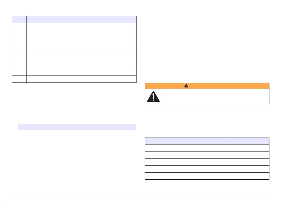
Tabella 11 Codici di stato (binari)
Codice Descrizione
1 Errore del sensore
2 Allarme di conteggio CH1
3 Errore del sensore e allarme di conteggio CH1
4 Allarme di conteggio CH2
5 Errore del sensore e allarme di conteggio CH2
6 Allarmi di conteggio CH1 e CH2
7 Errore del sensore, allarme di conteggio CH1 e allarme di conteggio
CH2
8 Allarme di flusso o allarme ingresso digitale
Visualizzazione o cancellazione del buffer (registro dati)
1. Premere F1 fino a visualizzare "Buff Count/View Buffer/ Delete Buffer
(Conteggio buffer/Visualizza buffer/Cancella buffer)", quindi premere
ENTER
(Invio).
2. Selezionare un'opzione. Per uscire, premere ENTER (Invio).
Opzione Descrizione
VIEW
(VISTA)
DEL
(CANC)
Consente di visualizzare i dati nel buffer (registro dati). I dati
più recenti vengono visualizzati per primi. I codici di stato
visualizzati sono:
A—Uno dei canali ha superato l'impostazione di allarme di
conteggio corrispondente.
S—Potrebbe essere necessario pulire la cella a flusso del
sensore.
Per tornare indietro, premere BAK. Per andare avanti,
premere NXT. Per uscire, premere ENTER (Invio).
Consente di cancellare tutti i dati nel buffer (registro dati).
Premere YES (Sì) per confermare o NO per uscire.
Identificare i valori di ingresso analogico
Premere F1 fino a che non viene visualizzato "Input 1/Input 2 (Ingresso
1/Ingresso 2)", quindi premere ENTER (Invio). Viene mostrata la
tensione fornita dallo strumento ausiliario collegato a ciascun ingresso
analogico. Queste informazioni non vengono salvate nel buffer nella
modalità autonoma, ma possono essere recuperate nella modalità di
rete.
Calibrazione
L'utente non deve calibrare lo
strumento rivolgersi al produttore. Vedere l'etichetta sullo strumento per
la data della calibrazione.
strumento. Per la calibrazione dello
Manutenzione
A V V E R T E N Z A
Pericoli multipli. Gli interventi descritti in questa sezione del
documento devono essere eseguiti solo da personale qualificato.
Pianificazione degli interventi di manutenzione
Nella Tabella 12 viene mostrata la pianificazione consigliata degli
interventi di manutenzione. Requisiti strutturali e condizioni di esercizio
possono aumentare la frequenza di alcuni interventi.
Tabella 12 Pianificazione degli interventi di manutenzione
Intervento 1 anno Se necessario
Calibrazione a pagina 54 X
pagina 55 X
Pulizia della cella a flusso del sensore a pagina 55 X
Sostituzione della cartuccia essiccante a pagina 55 X
Sostituzione di un fusibile a pagina 56 X
1
Necessario per mantenere la conformità agli standard JIS B 9925-1997
1
54 Italiano
Page 55

Pulizia della cella a flusso del sensore
A V V I S O
Non inserire la spazzola per pulizia nel raccordo del condotto del campione
quando la cella a flusso del sensore è asciutta, per evitare di danneggiarla.
Pulire periodicamente la cella a flusso del sensore. Inoltre, pulire la cella
a flusso del sensore prima dell'uso se lo strumento è rimasto inutilizzato
a lungo.
Attrezzi necessari:
• Spazzola per pulizia in dotazione
•
Acqua pulita
1. Aprire lo sportello della struttura. Allentare le quattro viti prigioniere
che fissano lo sportello della struttura.
2. Portare l'interruttore di alimentazione su Off.
3. Arrestare il flusso di acqua verso lo strumento.
4. Smontare il condotto del campione e il condotto di scarico dai
raccordi a compressione.
5. Collegare il condotto del campione al raccordo a compressione sulla
sommità del gruppo sensore.
6. Avviare il flusso di acqua verso lo strumento. Dopo 30 secondi,
arrestare il flusso.
7. Togliere il condotto del campione dal raccordo a compressione.
8. Pulire la cella a flusso del sensore.
a. Versare acqua pulita nel raccordo a compressione sulla sommità
del gruppo sensore. L'acqua verrà scaricata dal raccordo a
compressione del condotto del campione.
b. Inserire la spazzola per pulizia nel raccordo a compressione.
Muovere delicatamente avanti e indietro la spazzola due o tre
volte. Fare riferimento alla Figura 10.
c. Versare acqua pulita nel raccordo a compressione sulla sommità
del gruppo sensore. In questo modo, eventuali depositi staccati
dalla spazzola verranno lavati via.
d. Versare acqua pulita sopra la spazzola per pulizia per lavare via
eventuali depositi.
9. Collegare i tubi del condotto del campione e del condotto di scarico.
Fare riferimento a Collegamento dello strumento a pagina 49.
10. Avviare il flusso di acqua verso lo strumento.
11. Portare l'interruttore di alimentazione su On.
12. Chiudere lo sportello della struttura. Serrare le quattro viti prigioniere
che fissano lo sportello della struttura.
Figura 10 Pulizia della cella a flusso del sensore
Sostituzione della cartuccia essiccante
Sostituire la cartuccia essiccante quando il colore dei cristalli passa da
blu a rosa. Fare riferimento alla Figura 1 a pagina 43 per la posizione
della cartuccia essiccante.
Italiano 55
Page 56

L'uso di una cartuccia essiccante è necessario per impedire l'accumulo
di condensa nella struttura dello strumento. In questo modo si evita la
corrosione dei collegamenti elettrici sensibili e si contribuisce a prevenire
l'accumulo di condensa nel gruppo sensore.
Componenti necessari:
• Cartuccia essiccante
•
Striscia adesiva in Velcro
1. Aprire lo sportello della struttura. Allentare le quattro viti prigioniere
che fissano lo sportello della struttura.
2. Portare l'interruttore di alimentazione su Off.
3. Aprire il quadro elettrico. Ruotare le due viti prigioniere da ¼ di giro
solo di ¼ di giro.
4. Sostituire la cartuccia essiccante.
a. Staccare la cartuccia essiccante usata dalla striscia di Velcro sul
pannello posteriore e gettarla.
b. Posizionare una striscia adesiva in Velcro su una nuova cartuccia
essiccante.
c. Premere la cartuccia essiccante sulla striscia di Velcro sul
pannello posteriore.
5. Chiudere e fissare il quadro elettrico con le due viti da ¼ di giro.
6. Portare l'interruttore di alimentazione su On.
7. Chiudere lo sportello della struttura. Serrare le quattro viti prigioniere
che fissano lo sportello della struttura.
Sostituzione di un fusibile
P E R I C O L O
Pericolo di incendio. Utilizzare lo stesso tipo e corrente nominale per
sostituire i fusibili.
P E R I C O L O
Pericolo di folgorazione. Prima di eseguire questo intervento di
manutenzione, interrompere l'alimentazione elettrica allo strumento e
ai relè.
Componenti necessari:
• Fusibile, 5 x 20 mm T, 0,500 mA, 250 V
Cacciavite Phillips
•
1. Aprire lo sportello della struttura. Allentare le quattro viti prigioniere
che fissano lo sportello della struttura.
2. Portare l'interruttore di alimentazione su Off.
3. Aprire il quadro elettrico. Ruotare le due viti prigioniere da ¼ di giro
solo di ¼ di giro.
4. Sostituire il fusibile. Fare riferimento ai passaggi illustrati nella
Figura 11.
5. Assemblare lo strumento. Eseguire i passaggi illustrati nella
Figura 11 invertendone l'ordine.
6. Chiudere e fissare il quadro elettrico con le due viti da ¼ di giro.
7. Portare l'interruttore di alimentazione su On.
8. Chiudere lo sportello della struttura. Serrare le quattro viti prigioniere
che fissano lo sportello della struttura.
56 Italiano
Page 57

Figura 11 Sostituzione di un fusibile
Individuazione ed eliminazione dei guasti
Problema Possibile causa Soluzione
La spia POWER
(Alimentazione) non
si accende
La spia ALARM è
accesa
La spia ALARM
lampeggia
Non è presente
alimentazione allo
strumento o l'interruttore di
alimentazione è in
posizione Off.
È attivo un allarme di rete.
Nota: Un allarme di rete viene
attivato e disattivato solo dal
software di rete.
È attivo un allarme di
conteggio (solo in modalità
autonoma) o di flusso.
Nota: Se è attivo un allarme di
conteggio, la spia ALARM e il
canale interessato lampeggiano
sul display.
Assicurarsi che l'interruttore
di alimentazione sia
impostato su On.
Assicurarsi che sia presente
alimentazione allo
strumento.
—
Fare riferimento a
Configurazione del
contatore di particelle
a pagina 51 per la
configurazione delle
impostazioni per gli allarmi
di conteggio.
Problema Possibile causa Soluzione
La spia SENSOR è
accesa
La spia SENSOR
lampeggia
Due o più strumenti
non rispondono al
software di
monitoraggio
È attivo un errore di
calibrazione alta. Il sensore
è contaminato o il diodo
laser sta perdendo potenza.
È attivo un errore di
calibrazione bassa. Il
fotodiodo è saturo e deve
essere pulito, regolato o
sostituito.
Due o più strumenti hanno
lo stesso indirizzo. Gli
strumenti con lo stesso
indirizzo non risponderanno
al software di monitoraggio.
Pulire la cella a flusso. Fare
riferimento a Pulizia della
cella a flusso del sensore
a pagina 55.
Se l'errore di calibrazione
alta persiste, contattare
l'assistenza tecnica.
Pulire la cella a flusso. Fare
riferimento a Pulizia della
cella a flusso del sensore
a pagina 55.
Se l'errore di calibrazione
bassa persiste, contattare
l'assistenza tecnica.
Disattivare il software di
monitoraggio e assegnare
un indirizzo univoco agli
strumenti che hanno lo
stesso indirizzo. Fare
riferimento all'opzione Unit
ID (ID unità) in
Configurazione del
contatore di particelle
a pagina 51.
Messaggi di errore
Messaggio Possibile causa Soluzione
CAL
(Calibrazione)
FLOW (Flusso) Il dispositivo di
È attivo un errore di
calibrazione alta o bassa.
monitoraggio del flusso
esterno ha attivato un
allarme di flusso.
Pulire la cella a flusso. Fare
riferimento a Pulizia della cella a
flusso del sensore a pagina 55.
Se l'errore di calibrazione
persiste, contattare l'assistenza
tecnica.
Fare riferimento a Collegamento
dell'ingresso digitale (opzionale)
a pagina 47.
Italiano 57
Page 58

Parti di ricambio e accessori
A V V E R T E N Z A
Pericolo di lesioni personali. L'uso di parti non approvate può causare
lesioni personali, danni alla strumentazione o malfunzionamenti
dell'apparecchiatura. La parti di ricambio riportate in questa sezione
sono approvate dal produttore.
Nota: Numeri di Prodotti e Articoli possono variare per alcune regioni di vendita.
Contattare il distributore appropriato o fare riferimento al sito Web dell'azienda per
dati di contatto.
Parti di ricambio
Descrizione Articolo n.
Accessori (continua)
Descrizione Articolo n.
Tubo, opaco, diametro esterno 0,25 pollici, PTFE nero VP792021
Regolatore di flusso a barriera per la regolazione del
flusso
2081335-1
Ghiera, 6 mm, adattatore per raccordo a compressione da
0,25 pollici
Kit spazzole per pulizia, con due spazzole da 1 µm, per
WPC-22
Kit spazzole per pulizia, con due spazzole da 2 µm, per
WPC-21
Kit essiccante, con due cartucce di essiccante e due
etichette adesive in Velcro
Fusibile, 5 x 20 mm T, 0,500 mA, 250 V 500-150-0050
Cavo di alimentazione, 230 VCA 510667
Raccordo pressacavo per cavo di alimentazione VP752401
Raccordo pressacavo per connessioni esterne 570-730-2212
MP000147-01
SA000120-02
SA000120-01
SA000180-01
Accessori
Descrizione Articolo n.
Software AQUARIUS CS200011
Convertitore da RJ-45 a DB-9 SA000070-01
Convertitore da RS485/RS422 a USB 5920400
58 Italiano
Page 59

Caractéristiques
Les caractéristiques techniques peuvent être modifiées sans préavis.
Caractéristique Détails
Dimensions (l x P x H) 248 x 114 x 302 mm (9,75 x 4,50 x 11,88 po) avec
Boîtier NEMA 4X
Source de lumière 780 nm, 5 mW classe 3B diode laser ; durée de vie
Détecteur Photodiode
Ecran LCD, 4 lignes x 16 caractères
Tailles des ports Deux raccords de compression pour tube d'entrée
Matériaux mouillés Silice fondue, Viton (fluorocarbure) et Kynar (PVDF)
Cellule d'écoulement WPC-21 : 600 x 600 µm de silice fondue avec
Poids 2,25 kg (5 lb)
Catégorie d’installation II
Classe de protection I
Niveau de pollution 2
Environnement
d’exploitation
Environnement de
stockage
Altitude 2 000 m (6 562 pieds) maximum
Alimentation requise 230 VCA ±15 %, 20 VA, 50/60 Hz
capteur et supports de montage
de 30 000 heures
et de sortie avec diamètre externe de 0,25 pouce
revêtements anti-reflets
WPC-22 : 800 x 800 µm de silice fondue avec
revêtements anti-reflets
WPC-21 : 5 à 40 °C (41 à 104 °F), 5 à 90 %
d'humidité relative sans condensation
WPC-22 : 5 à 45 °C (41 à 113 °F), 5 à 90 %
d'humidité relative sans condensation
-20 à 60 °C (-4 à 140 °F), 98 % d'humidité relative
sans condensation (maximum)
Caractéristique Détails
Méthode de détection Blocage de la lumière
Etalonnage WPC-21 : étalonné en usine à un débit
Tailles de particules WPC-21 : 1,3, 2, 3, 5, 7, 10, 15 et 25 µm
Coïncidences WPC-21 : 10 % de perte à 25 000 particules/ml
Nombre de canaux Deux canaux ; canal 1 : particules les plus petites,
Unités de mesure Nombre de particules par ml
Résolution du capteur Moins de 10 % à 10 µm tel que décrit dans ASTM-
Efficacité du décompte de
capteur
Pression d'échantillon 8,3 bars (120 psi) maximum
Débit d'échantillon WPC-21 : 45-55 ml/minute
Température de
l'échantillon
Entrée numérique Une ; 0-10 VCC, ±24 VCC < 10 mA
Sorties numériques Deux ; collecteur ouvert (100 mA, 24 VCC
Entrées analogiques Deux ; 0-10 VCC
Sorties analogiques 2 canaux : 4-20 mA
d'écoulement de 50 ml/minute, traçable NIST, huit
tailles de particules
WPC-22 : étalonné en usine à un débit
d'écoulement de 100 ml/minute, traçable NIST, huit
tailles de particules
WPC-22 : 2, 5, 7, 10, 15, 25, 50 et 100 µm
WPC-22 : 10 % de perte à 15 000 particules/ml
canal 2 : l'une des sept autres tailles de particules
(fixes) ou les sept tailles de particules (défilement)
F658-87
Est conforme aux normes JIS 9925 B-1997
WPC-22 : 90-110 ml/minute
0 à 50 °C (32 à 122 °F), sans gel
maximum)
Français 59
Page 60

Caractéristique Détails
Communications RS485 (protocole : MODBUS) ou RS232, fil à paire
Stockage des données 100 enregistrements
Certifications CE (directive sur les basses tensions)
torsadée blindée 19 AWG
Généralités
En aucun cas le constructeur ne saurait être responsable des
dommages directs, indirects, spéciaux, accessoires ou consécutifs
résultant d'un défaut ou d'une omission dans ce manuel. Le constructeur
se réserve le droit d'apporter des modifications à ce manuel et aux
produits décrits à tout moment, sans avertissement ni obligation. Les
éditions révisées se trouvent sur le site Internet du fabricant.
Consignes de sécurité
A V I S
Le fabricant décline toute responsabilité quant aux dégâts liés à une application
ou un usage inappropriés de ce produit, y compris, sans toutefois s'y limiter, des
dommages directs ou indirects, ainsi que des dommages consécutifs, et rejette
toute responsabilité quant à ces dommages dans la mesure où la loi applicable le
permet. L'utilisateur est seul responsable de la vérification des risques
d'application critiques et de la mise en place de mécanismes de protection des
processus en cas de défaillance de l'équipement.
Veuillez lire l'ensemble du manuel avant le déballage, la configuration ou
la mise en fonctionnement de cet appareil. Respectez toutes les
déclarations de prudence et d'attention. Le non-respect de cette
procédure peut conduire à des blessures graves de l'opérateur ou à des
dégâts sur le matériel.
Assurez-vous que la protection fournie avec cet appareil n'est pas
défaillante. N'utilisez ni n'installez cet appareil d'une façon différente de
celle décrite dans ce manuel.
Interprétation des indications de risques
D A N G E R
Indique une situation de danger potentiel ou imminent qui, si elle n'est pas évitée,
entraîne des blessures graves, voire mortelles.
A V E R T I S S E M E N T
Indique une situation de danger potentiel ou imminent qui, si elle n'est pas évitée,
peut entraîner des blessures graves, voire mortelles.
Indique une situation de danger potentiel qui peut entraîner des blessures
mineures ou légères.
Indique une situation qui, si elle n'est pas évitée, peut occasionner
l'endommagement du matériel. Informations nécessitant une attention
particulière.
A T T E N T I O N
A V I S
Étiquettes de mise en garde
Lisez toutes les informations et toutes les étiquettes apposées sur
l’appareil. Des personnes peuvent se blesser et le matériel peut être
endommagé si ces instructions ne sont pas respectées. Un symbole sur
l'appareil est désigné dans le manuel avec une instruction de mise en
garde.
Si l'appareil comporte ce symbole, reportez-vous au manuel
d'utilisation pour consulter les informations de fonctionnement et de
sécurité.
S'il se trouve sur l’emballage d'un produit ou une barrière, ce symbole
indique la présence d’un danger de choc électrique et/ou
d’électrocution.
Les composants électroniques internes de l'appareil peuvent être
endommagés par l'électricité statique, qui risque d'altérer ses
performances et son fonctionnement.
60 Français
Page 61

Ce symbole indique qu'un dispositif laser est utilisé dans
l'équipement.
Ce symbole indique l’emplacement d’un fusible ou de tout dispositif
de protection contre les surintensités de courant.
En Europe, depuis le 12 août 2005, les appareils électriques
comportant ce symbole ne doivent pas être jetés avec les autres
déchets. Conformément à la réglementation nationale et européenne
(Directive 2002/96/CE), les appareils électriques doivent désormais
être, à la fin de leur service, renvoyés par les utilisateurs au fabricant,
qui se chargera de les éliminer à ses frais.
Remarque : Pour le retour à des fins de recyclage, veuillez contactez le fabricant
ou le fournisseur d'équipement afin d'obtenir les instructions sur la façon de
renvoyer l'équipement usé, les accessoires électriques fournis par le fabricant, et
tous les articles auxiliaires pour une mise au rebut appropriée.
Conformité
Ce symbole indique que
l'appareil est un produit
LASER de classe 1.
Ce produit est conforme aux normes IEC/EN 60825-1:2007 et 21 CFR
1040.10, à l'exception des différences faisant suite à la notice Laser n°
50 datée du 24 juin 2007. Numéro d'accession FDA : 9020917.
Ce produit est également certifié conforme CE. Contactez le fabricant
pour avoir tous les détails sur la conformité.
Certification
Règlement canadien sur les équipements causant des
interférences radio, IECS-003, Classe A:
Les données d'essai correspondantes sont conservées chez le
constructeur.
Cet appareil numérique de classe A respecte toutes les exigences du
Règlement sur le matériel brouilleur du Canada.
Cet appareil numérique de classe A répond à toutes les exigences de la
réglementation canadienne sur les équipements provoquant des
interférences.
FCC part 15, limites de classe A :
Les données d'essai correspondantes sont conservées chez le
constructeur. L'appareil est conforme à la partie 15 de la règlementation
FCC. Le fonctionnement est soumis aux conditions suivantes :
1. Cet équipement ne peut pas causer d'interférence nuisible.
2. Cet équipement doit accepter toutes les interférences reçues, y
compris celles qui pourraient entraîner un fonctionnement inattendu.
Les modifications de cet équipement qui n’ont pas été expressément
approuvées par le responsable de la conformité aux limites pourraient
annuler l’autorité dont l’utilisateur dispose pour utiliser cet équipement.
Cet équipement a été testé et déclaré conforme aux limites définies pour
les appareils numériques de classe A, conformément à la section 15 de
la réglementation FCC. Ces limites ont pour but de fournir une protection
raisonnable contre les interférences néfastes lorsque l’équipement
fonctionne dans un environnement commercial. Cet équipement génère,
utilise et peut irradier l'énergie des fréquences radio et, s'il n'est pas
installé ou utilisé conformément au mode d'emploi, il peut entraîner des
interférences dangereuses pour les communications radio. Le
fonctionnement de cet équipement dans une zone résidentielle risque de
causer des interférences nuisibles, dans ce cas l'utilisateur doit corriger
les interférences à ses frais Les techniques ci-dessous peuvent
permettre de réduire les problèmes d'interférences :
1. Débrancher l'équipement de la prise de courant pour vérifier s'il est
ou non la source des perturbations
2. Si l'équipement est branché sur le même circuit de prises que
l'appareil qui subit des interférences, branchez l'équipement sur un
circuit différent.
3. Éloigner l'équipement du dispositif qui reçoit l'interférence.
4. Repositionner l’antenne de réception du périphérique qui reçoit les
interférences.
5. Essayer plusieurs des techniques ci-dessus à la fois.
Français 61
Page 62

Présentation du produit
Cet instrument sert à contrôler en continu la contamination de l'eau par
des particules. Voir Figure 1. Cet instrument est généralement utilisé
pour contrôler les usines de traitement d'eau privées, industrielles et
municipales.
Cet instrument est composé de deux canaux. Le canal 1 contrôle les
particules les plus petites. Le canal 2 peut être configuré pour contrôler
l'une des sept autres tailles de particules (fixes) ou l'ensemble des sept
autres tailles de particules (défilement). Reportez-vous à la
Caractéristiques à la page 59 pour connaître les tailles des particules
contrôlées.
Cet instrument peut être utilisé comme unité individuelle (autonome) ou
dans un réseau d'unités connectées via le logiciel AQUARIUS ou un
logiciel fourni par l'utilisateur. Pour obtenir des informations sur le logiciel
d'acquisition de données AQUARIUS, reportez-vous à sa
documentation.
Figure 1 Présentation de l'instrument
1 Porte du boîtier 5 Ensemble du capteur
2 Sachet dessiccatif 6 Raccord de conduite d'échantillon
3 Interrupteur marche/arrêt 7 Panneau d'accès électrique et
4 Raccord de conduite de vidange
interface utilisateur
62 Français
Composants du produit
Assurez-vous d'avoir bien reçu tous les composants. Voir Figure 2. Si
des éléments manquent ou sont endommagés, contactez
immédiatement le fabricant ou un représentant commercial.
Page 63

Figure 2 Composants du produit
1 Arrêtoirs de charnières, pièces de
rechange (4x)
2 WPC-21 ou WPC-22 6 Vis pour supports de montage
3 Adaptateurs pour virole de 6 mm
pour raccord de compression de
0,25 pouce (2x)
4 Bandes adhésives Velcro pour
sachets dessiccatifs (2x)
5 Sachets dessiccatifs (2x)
mural (4x)
7 Supports de montage mural (4x)
8 Kit de nettoyage avec deux brosses
de nettoyage
Installez l'instrument :
• Aussi près que possible de la source d'échantillon pour réduire le
décalage d'analyse
•
Dans un emplacement propre, sec, bien ventilé, à température
régulée, avec un minimum de vibrations et sans exposition à la
lumière solaire directe
• Dans un boîtier d'environnement assurant la protection contre les
précipitations et la lumière solaire directe, avec une bonne ventilation
et un bon contrôle de température en cas d'installation à l'extérieur
• Dans un endroit où l'interrupteur et le cordon d'alimentation sont
visibles et facilement accessibles
• Dans un emplacement présentant suffisamment d'espace autour pour
réaliser des branchements de tuyauterie et électriques
Installation mécanique
Fixation de l'instrument sur un mur
Fixez l'instrument à la verticale et alignez-le sur une surface plane
verticale. Reportez-vous aux procédures présentées à la Figure 3. Le
matériel de montage est fourni par l'utilisateur.
Le débit d'échantillon doit toujours être opposé, à la gravité afin d'éviter
que des bulles ne soient bloquées dans le capteur. L'écoulement se fait
du bas vers le haut du sous-ensemble du capteur.
Remarque : l'instrument peut être fixé à un panneau existant. Installez des vis
directement sur le panneau arrière ou utilisez le matériel de montage fourni.
Installation
Conseils d'installation
Risque d’incendie. Ce produit n'est pas adapté à l'utilisation avec des
liquides inflammables.
D A N G E R
Français 63
Page 64

Figure 3 Montage sur un mur
Installation électrique
D A N G E R
Risque d'électrocution Débranchez systématiquement l'alimentation de
l'appareil avant tout branchement électrique.
D A N G E R
Risque d'électrocution Si cet équipement est utilisé à l'extérieur ou
dans des lieux potentiellement humides, un disjoncteur de fuite à la
terre (GFCI/GFI) doit être utilisé pour le branchement de l'équipement
à sa source d'alimentation secteur.
Risque d'électrocution Un raccordement à la terre est nécessaire.
Utilisez un câble à paire torsadée blindé pour tous les branchements
électriques sauf l'alimentation. L'utilisation d'un câble non blindé peut
conduire à l'émission de fréquences radio ou à des niveaux de
susceptibilité supérieurs à ceux autorisés.
Pour éviter tout choc électrique des courants à la terre dans les
systèmes inadéquats, connectez le câble blindé uniquement à
l'extrémité de l'instrument. Ne connectez pas le câble blindé aux deux
extrémités.
Branchements électriques
Risque d'électrocution. N'utilisez pas le conduit pour fournir
l'alimentation électrique. Le boîtier n'est muni d'aucune connexion de
mise à la terre.
D A N G E R
D A N G E R
64 Français
D A N G E R
Risque d'électrocution Débranchez systématiquement l'alimentation de
l'appareil avant tout branchement électrique.
Page 65

La Figure 4 présente les branchements et la procédure de câblage
générale.
Effectuez tous les branchements électriques via les raccords
détendeurs. Pour conserver le classement du boîtier :
•
Ne placez pas plus d'un câble (ou deux fils) à travers un raccord
détendeur.
• Assurez-vous que les raccords détendeurs inutilisés sont équipés de
prises pour câble en caoutchouc. Utilisez des raccords détendeurs
dont le classement environnemental est approprié.
Respectez l'ensemble des codes et réglementations relatifs aux
câblages. Serrez les raccords détendeurs pour maintenir fermement les
câbles.
Figure 4 Présentation du câblage
Branchement des sorties analogiques (en option)
Deux sorties analogiques 4-20 mA (AO1 et AO2) sont disponibles sur le
connecteur J3. Le signal de sortie analogique est proportionnel au
décompte/ml du canal. Le décompte/ml pour le canal 1 est représenté
sur AO1. Le décompte/ml pour le canal 2 est représenté sur AO2.
Reliez un dispositif alimenté à chaque sortie analogique avec un fil
24-28 AWG. Voir Tableau 1.
Si le ou les dispositifs alimentés ont une résistance de charge d'au
moins 500 ohms, fournissez une tension externe (40 VCC maximum)
vers Vext– et Vext+ du connecteur J1 pour fournir suffisamment de
tension au dispositif alimenté.
Tableau 1 Branchement des sorties analogiques (4-20 mA)
Broche Description
AO2– Neutre
AO2+ Positif
AO1– Neutre
AO1+ Positif
Branchement des entrées analogiques (en option)
Deux entrées analogiques (AI1 et AI2) sont disponibles sur le
connecteur J3. Reliez des instruments auxiliaires (c'est-à-dire des
débitmètres, des appareils de mesure de la turbidité, des transducteurs
de pression, des appareils de mesure de pH) aux entrées analogiques
pour afficher la tension fournie par les instruments auxiliaires sur l'écran
de l'instrument (0-10 VCC). Voir Identification des valeurs d'entrées
analogiques à la page 74.
Reliez un instrument auxiliaire à chaque entrée analogique avec un fil
22-24 AWG. Utilisez un fil 19 AWG si le fil mesure au moins 7,62 m
(25 pieds). Voir Tableau 2.
1 Branchement des entrées/sorties
analogiques
2 Branchements de communication
(RS232 et RS485)
3 Branchements d'alarme (sorties
numériques)
4 Raccord détendeur pour
branchements externes (4x)
Français
65
Page 66

Tableau 2 Branchement des entrées analogiques (0-10 VCC)
Broche Description
AI2– Neutre
AI2+ Positif
AI1– Neutre
AI1+ Positif
Tableau 3 Description des sorties numériques
Sortie numérique Description
Broche ALM Est alimentée lorsqu'une alarme d'écoulement ou une
alarme de décompte est activée. Reportez-vous à la section
Configuration du compteur de particules à la page 71 pour
configurer l'alarme d'écoulement et l'alarme de décompte.
Broche CAL Est alimentée lorsqu'une erreur d'étalonnage élevé ou faible
est activée.
Branchement des entrées numériques (en option)
Une entrée numérique est disponible sur le connecteur J4. Reliez un
dispositif de contrôle d'écoulement à l'entrée numérique (broche CTS)
pour déclencher une alarme d'écoulement lorsque la tension sur l'entrée
numérique est élevée ou faible, selon le paramètre d'état de l'alarme
d'écoulement. Reportez-vous à la section Configuration du compteur de
particules à la page 71 pour configurer le paramètre d'état de l'alarme
d'écoulement et activer l'alarme d'écoulement.
Reliez le dispositif de contrôle d'écoulement à la broche CTS avec un fil
24-28 AWG.
Remarque : l'entrée numérique n'est pas disponible lorsque la connexion
RS232 est utilisée pour connecter une imprimante ou un ordinateur.
Branchement des sorties numériques (en option)
Deux sorties numériques (ALM et CAL) sont disponibles sur le
connecteur J1. Voir Tableau 3. Reliez un dispositif compatible, comme
un indicateur d'alarme à distance ou une sonnerie, à la sortie numérique
applicable avec un fil 24-48 AWG.
Les broches ALM et CAL sont des sorties à collecteur ouvert qui
fournissent une mise à la terre une fois alimentées. Respectez les
classements de sorties numériques de la section Caractéristiques
à la page 59.
66 Français
Connexion d'un périphérique série (en option)
Une connexion RS232 est disponible sur le connecteur J4. Reliez une
imprimante ou le port série d'un ordinateur (COM 1 ou COM 2) à la
connexion RS232 pour envoyer les données en mémoire tampon vers
une imprimante ou un ordinateur. Voir Envoi du journal des données à
une imprimante ou un ordinateur à la page 73.
Si le convertisseur RJ-45 vers DB-9 en option est utilisé, coupez un
câble RJ-45, puis séparez et identifiez les fils. Voir Figure 5. Reportezvous au
Tableau 4 pour connaître le branchement du câblage RS232.
Remarque : la connexion RS232 n'est pas disponible lorsque l'entrée numérique
(broche CTS) est utilisée.
Page 67

Figure 5 Câblage du convertisseur RJ-45 vers DB-9
1 Vers un PC ou une
imprimante
2 Convertisseur
RJ-45 vers
DB-9 (SA000070-01)
3 Câble RJ-45 (fourni
par l'utilisateur)
Tableau 4 Connexions RS232
Broche DB-9 Broche RJ-45 Broche J4
Broche 2 RX Broche 3 TX
Broche 3 TX Broche 4 RX
Broche 4 DTR Broche 5 CTS
Broche 5 GND Broche 8 GND
Alimentation d'un dispositif externe (en option)
+5 VCC ou +12 VCC disponible sur JP1 pour alimenter un dispositif
externe. +5 VCC est fourni lorsque le cavalier est sur la broche +5 V et
la broche 2 de JP1. +12 VCC est fourni lorsque le cavalier est sur la
broche Vps et la broche 2 de JP1.
Remarque : La broche V+ et la broche GND sur le connecteur J1 servent
uniquement à la maintenance.
Branchement des unités à un réseau (en option)
Plusieurs unités peuvent être connectées ensemble dans un réseau.
Utilisez la connexion RS485 de chaque unité et un fil à paire torsadée
blindée 19 AWG pour relier les unités.
Remarques :
Un maximum de 32 unités dans un réseau peut être connecté à un
•
réseau RS485.
•
L'ordinateur hôte doit disposer d'un logiciel d'acquisition de données.
• Le protocole de communication est Modbus. Reportez-vous à la
documentation Modbus WPC sur le site Web du fabricant.
1. Sur la première unité :
a. Appuyez sur le câble entrant depuis le convertisseur
RS232/RS485 via un raccord détendeur.
b. Appuyez sur le câble sortant via un raccord détendeur.
c. Reliez les câbles entrant et sortant au connecteur J4. Voir
Tableau 5.
2. Sur la seconde unité :
a. Appuyez sur le câble entrant depuis la première unité via un
raccord détendeur.
b. Appuyez sur le câble sortant via un raccord détendeur.
c. Reliez les câbles entrant et sortant au connecteur J4. Voir
Tableau 5.
3. Effectuez à nouveau l'étape 2 pour la troisième unité et les unités
restantes, jusqu'à ce que toutes les unités aient des connexions
entrantes et sortantes. La dernière unité n'aura pas de câble sortant.
Remarque : dans une installation en réseau, le câble sortant de l'unité
précédente correspond toujours au câble entrant de l'unité suivante.
4. Sur la dernière unité, installez un cavalier sur JP2. N'installez pas de
cavalier sur JP2 sur les autres unités.
Français 67
Page 68

5. Définissez l'option MODE sur N (mode réseau). Reportez-vous à
l'option Date/MODE à la section Configuration du compteur de
particules à la page 71.
6. Attribuez une adresse unique à chaque unité. Reportez-vous à
l'option Unit ID (ID d'unité) à la section Configuration du compteur de
particules à la page 71.
Tableau 5 Connexions RS485
Câble Broche J4
– RS485 A
+ RS485 B
Blindage SGND
Plomberie
Raccordement de l'instrument
Eléments à préparer :
• Tube opaque de diamètre externe 6 mm
•
Deux viroles de 6 mm
Sélectionnez le tube en fonction des pires conditions environnementales
possibles (par ex. plage de température, exposition aux rayons du soleil,
polluants dans l'air) et de la pression d'entrée la plus élevée possible
(120 psi maximum).
1. Retirez le tube du raccord de conduite d'échantillon et du raccord de
conduite de vidange et mettez-les au rebut. Ne réutilisez pas le tube
pour la conduite d'échantillon ou de vidange.
2. Reliez une conduite d'échantillon au raccord de conduite
d'échantillon sur le boîtier de l'instrument. Voir Figure 6.
3. Reliez une conduite de vidange au raccord de conduite de vidange
sur le boîtier de l'instrument. Voir Figure 6.
4. Installez un détendeur en Y dans la conduite d'échantillon, si
nécessaire, afin d'éviter que de grosses particules n'entrent dans le
capteur et n'entraînent une obstruction.
5. Installez une vanne d'isolation manuelle dans la conduite
d'échantillon, afin que l'écoulement vers l'instrument puisse être
interrompu, si nécessaire.
Figure 6 Raccordement de l'instrument
1 Raccord de conduite d'échantillon 3 Ecrou en plastique
2 Raccord de conduite de vidange 4 Virole, 6 mm
Directives de ligne d'échantillonnage
Choisissez un point d'échantillonnage adapté et représentatif pour
garantir le fonctionnement optimal de l'instrument. L'échantillon doit être
représentatif de l'ensemble du système.
Pour éviter les relevés irréguliers :
prélevez les échantillons à des endroits suffisamment éloignés des
•
points d'ajout de produits chimiques au flux à traiter ;
•
assurez-vous que les échantillons sont suffisamment mélangés ;
• assurez-vous que toutes les réactions chimiques sont bien terminées.
68 Français
Page 69

Raccordement du flux d'échantillon
Installez la conduite d'échantillon dans une canalisation de processus
plus grande pour réduire les interférences provenant des bulles d'air ou
des sédiments déposés au fond de la canalisation. Le mieux est une
conduite d'échantillon allant au centre d'une canalisation de processus.
La Figure 7 illustre des exemples de méthodes correctes et incorrectes
pour l'installation d'une conduite d'échantillonnage dans une canalisation
industrielle.
Maintenez la conduite d'échantillonnage aussi courte que possible pour
réduire les retards d'analyse. Les sédiments peuvent aussi se déposer
dans des conduites d'échantillonnage trop longues.
Figure 7 Méthodes d'échantillonnage
1 Air 2 Débit de l'échantillon
2. Ouvrez la porte du boîtier. Desserrez les quatre vis imperdables qui
fixent la porte du boîtier.
3. Placez l'interrupteur d'alimentation sur marche.
4. Fermez la porte du boîtier. Serrez les quatre vis imperdables qui
fixent la porte du boîtier.
Interface utilisateur et navigation
Interface utilisateur
La Figure 8 présente l'écran, le clavier et les voyants. Reportez-vous au
Tableau 6 pour obtenir une description des touches. Reportez-vous au
Tableau 7 pour obtenir une description des voyants.
Mise en marche
Mise sous tension
1. Branchez le cordon d'alimentation à une prise électrique avec mise à
la terre.
Français 69
Page 70

Figure 8 Interface utilisateur
1 Voyant d'alarme 5 Voyant d'alimentation
2 Touche F1 6 Touche ENTER (ENTREE)
3 Touche START/STOP
(MARCHE/ARRET)
4 Ecran 8 Voyant du capteur
7 Touche F2
Tableau 6 Description des touches
Touche Description
START/STOP
(MARCHE/ARRET)
F1 Permet de parcourir les menus et de modifier les
Permet de démarrer ou d'interrompre le
décompte des particules
paramètres
Tableau 6 Description des touches (suite)
Touche Description
F2 Permet de parcourir les menus et de modifier les
paramètres
ENTER (ENTREE) Confirmer, entrer ou sélectionner. Appuyez pour
enregistrer le décompte actuel dans la mémoire
tampon (mode autonome uniquement).
Tableau 7 Description des voyants
Voyant Couleur Description
Alimentation Vert L'instrument est alimenté et l'interrupteur est activé.
Alarme Rouge Voyant fixe : une alarme réseau est activée.
Voyant clignotant : une alarme de décompte ou une
alarme d'écoulement est activée.
Voir Dépannage à la page 77.
Capteur Jaune Voyant fixe : une erreur d'étalonnage élevé est activée.
Voyant clignotant : une erreur d'étalonnage faible est
activée.
Voir Dépannage à la page 77.
Description de l'affichage
La Figure 9 présente les informations indiquées à l'écran.
Lorsqu'une erreur d'étalonnage ou une alarme d'écoulement survient, un
message d'erreur s'affiche à l'écran. Voir Messages d’erreur
à la page 78.
70 Français
Page 71

Figure 9 Ecran de comptage
1 Taille de particule contrôlée sur le
canal 2
2 Taille de particule contrôlée sur le
canal 1
3 Décompte de particules sur le
canal 1
4 Décompte de particules sur le
canal 2
5 Fonctions des touches F1 et F2
Fonctionnement
Configuration du compteur de particules
Le compteur de particules peut être configuré pour un fonctionnement
autonome ou en réseau. En mode réseau, les paramètres de mise en
mémoire tampon des données, d'impression et de dimension du
canal 2 sont modifiés à l'aide du logiciel réseau. Par conséquent, ces
paramètres n'apparaissent pas sur l'écran de l'instrument.
1. Appuyez sur F1 pour choisir une option, puis sur ENTER (ENTREE).
Le ou les paramètres actuels s'affichent.
Mode autonome uniquement
Option Description
Intervals (Intervalles) BUF (Mémoire tampon) : définit l'intervalle
Buff Count/Print
Buff/Download
(Décompte
tampon/Imprimer
tampon /Télécharger)
tampon (journal des données). Options : OFF
(désactivé), 30 secondes, 1, 5, 10, 30 ou
60 minutes.
A la fin de chaque intervalle tampon, la date,
l'heure, l'état du capteur et le décompte sont
enregistrés dans la mémoire tampon. La
mémoire tampon contient un maximum de
100 enregistrements. Lorsque la mémoire
tampon est saturée, les nouvelles données
écrasent les données les plus anciennes.
Remarque : si une imprimante série est reliée, chaque
fois que des données sont enregistrées dans la mémoire
tampon, ces données sont également envoyées à
l'imprimante.
SCRL (Défilement) : définit l'intervalle de
défilement. Options : OFF (désactivé),
30 secondes, 1, 5, 10, 30 ou 60 minutes.
A la fin de chaque intervalle de défilement,
l'instrument commence à contrôler la taille de
particule étalonnée suivante sur le canal 2.
Lorsque cette option est désactivée, la taille de
particule contrôlée sur le canal 2 correspond au
paramètre de dimension du canal 2.
Remarque : aucune donnée ne sera enregistrée dans la
mémoire tampon si l'intervalle tampon est plus long que
l'intervalle de défilement.
Voir Envoi du journal des données à une
imprimante ou un ordinateur à la page 73. La
valeur Buff Count (Décompte tampon) indiquée
correspond au nombre d'entrées dans la
mémoire tampon (journal des données).
Français 71
Page 72

Option Description
Buff Count/View
Buffer/Delete Buffer
(Décompte tampon/Voir
tampon/Supprimer
tampon)
Count Alarms (Alarmes
décompte)
Mode réseau uniquement
Option Description
Unit ID = 1 (ID
d'unité = 1)
Voir Affichage ou suppression de la mémoire
tampon (journal des données) à la page 74. La
valeur Buff Count (Décompte tampon) indiquée
correspond au nombre d'entrées dans la
mémoire tampon (journal des données).
Définit le nombre minimal de particules qui
déclenchent une alarme de décompte sur le
canal 1 et le canal 2. Pour désactiver l'option,
définissez-le sur 0.
A1 : limite de décompte pour le canal 1
A2 : limite de décompte pour le canal 2
Appuyez sur INC pour modifier le chiffre
sélectionné. Appuyez sur la flèche DROITE pour
sélectionner le chiffre suivant.
Définit une adresse unique pour l'instrument. Options :
1 à 247. L'adresse 0 ne peut pas être utilisée. Cette
option apparaît uniquement lorsque l'option MODE est
définie sur N (pour « network », réseau), c'est-à-dire le
mode réseau.
Modes autonome et réseau
Option Description
Analog Count Out/Upper 1/Lower
1 (Décompte sortie
analogique/Supérieure 1/Inférieure 1)
Analog Count Out/Upper 2/Lower
2 (Décompte sortie
analogique/Supérieure 2/Inférieure 2)
Channel 2 Size (Taille canal 2) Appuyez sur les flèches HAUT
Flow Rate/Flow Alarm (Débit
d'écoulement/Alarme d'écoulement)
Définit les limites de décompte
(plage) pour la sortie analogique
(4-20 mA) du canal 1.
UL1 : limite de décompte
supérieure qui correspondra à
un signal de sortie 20 mA
LL1 : limite de décompte
inférieure qui correspondra à un
signal de sortie 4 mA
Définit les limites de décompte
(plage) pour la sortie analogique
(4-20 mA) du canal 2.
UL2 : limite de décompte
supérieure qui correspondra à
un signal de sortie 20 mA
LL2 : limite de décompte
inférieure qui correspondra à un
signal de sortie 4 mA
et BAS pour définir la taille de
particule contrôlée sur le
canal 2 lorsque l'intervalle de
défilement est désactivé.
RATE (Débit) : permet de saisir
le débit d'écoulement
ALM (Alarme) : permet d'activer
ou de désactiver l'alarme
d'écoulement. Si un dispositif de
contrôle d'écoulement est
disponible, l'alarme
d'écoulement est contrôlée au
niveau de l'entrée numérique
(broche CTS).
72 Français
Page 73

Option Description
Flow Alarm State Active (Etat
d'activation de l'alarme d'écoulement)
Input 1/Input 2 (Entrée 1/Entrée 2) Voir Identification des valeurs
Contrast/Beep (Contraste/Signal
sonore)
Date/MODE Date : permet de saisir la date
Définit l'alarme d'écoulement
pour un déclenchement sur une
entrée de tension élevée ou
faible sur la broche CTS, selon
l'état d'activation du dispositif
d'alarme d'écoulement.
Options : HI (Elevé) ou LO
(Faible).
Si l'option Flow Alarm State
Active (Etat d'activation de
l'alarme d'écoulement) est
définie sur HI (Elevé), une
entrée de tension élevée (>
2,5 VCC) sur la broche CTS
depuis le dispositif de contrôle
d'écoulement déclenche une
alarme d'écoulement et 0 V
correspond à un écoulement
normal.
d'entrées analogiques
à la page 74.
CON (Contraste) : permet
d'ajuster le contraste
BEP (Signal sonore) : permet
d'activer ou de désactiver le
signal sonore
et l'heure (format 24 h)
MODE : permet de définir le
mode. Options : S (« stand
alone ») pour le mode
autonome, ou N (« network »)
pour le mode réseau
Envoi du journal des données à une imprimante ou un ordinateur
Les données en mémoire tampon (journal des données) peuvent être
envoyées à une imprimante ou un ordinateur relié. Voir Connexion d'un
périphérique série (en option) à la page 66.
1. Définissez le port série d'ordinateur et/ou l'imprimante sur
9 600 baud, 8 données, aucune parité, 1 bit d'arrêt et pas de contrôle
d'écoulement.
Remarque :
complètes si l'appareil est incapable de recevoir continuellement à 9 600 baud.
2. Appuyez sur F1 jusqu'à ce que « Buff Count/Print Buff/Download »
(Décompte tampon/Imprimer tampon/Télécharger) s'affiche, puis sur
ENTER (ENTREE).
3. Sélectionnez une option. Pour sortir, appuyez sur ENTER
(ENTREE).
Option Description
PRT Envoie les données en mémoire tampon (journal des données) à
DNLD Envoie les données en mémoire tampon (journal des données) à
Code Description
1 Erreur de capteur
2 Alarme de décompte du canal 1
3 Erreur de capteur et alarme de décompte du canal 1
4 Alarme de décompte du canal 2
5 Erreur de capteur et alarme de décompte du canal 2
L'ordinateur ou l'imprimante ne recevront pas de transmissions
l'imprimante ou l'écran du terminal relié. Les données les plus
anciennes sont envoyées en premier. Reportez-vous au Tableau 11
pour connaître les codes d'état du capteur.
l'ordinateur relié. Reportez-vous au Tableau 11 pour connaître les
codes d'état du capteur.
Tableau 11 Codes d'état (binaire)
Français 73
Page 74

Tableau 11 Codes d'état (binaire) (suite)
Code Description
6 Alarmes de décompte des canaux 1 et 2
7 Erreur de capteur, alarme de décompte du canal 1 et alarme de
décompte du canal 2
8 Alarme d'écoulement ou alarme d'entrée numérique
Affichage ou suppression de la mémoire tampon (journal des données)
1. Appuyez sur F1 jusqu'à ce que « Buff Count/View Buffer/ Delete
Buffer » (Décompte tampon/Voir tampon/Supprimer tampon)
s'affiche, puis sur ENTER (ENTREE).
2. Sélectionnez une option. Pour sortir, appuyez sur ENTER
(ENTREE).
Option Description
VIEW
(AFFICHAGE)
DEL
(SUPPRIMER)
Affiche les données en mémoire tampon (journal des
données). Les données les plus récentes sont affichées
en premier. Les codes d'état indiqués sont les suivants :
A : l'un des canaux dépasse le paramètre d'alarme de
décompte pour le canal.
S : il est peut-être nécessaire de nettoyer la cellule
d'écoulement du capteur.
Pour revenir en arrière, appuyez sur BAK (RETOUR).
Pour avancer, appuyez sur NXT (SUIVANT). Pour sortir,
appuyez sur ENTER (ENTREE).
Supprime toutes les données en mémoire tampon
(journal des données). Appuyez sur YES (OUI) pour
confirmer ou NO (NON) pour quitter.
Identification des valeurs d'entrées analogiques
Appuyez sur F1 jusqu'à ce que « Input 1/Input 2 » (Entrée 1/Entrée 2)
s'affiche, puis sur ENTER (ENTREE). La tension fournie par l'instrument
auxiliaire connecté à chaque entrée analogique s'affiche. Cette
information n'est pas mise en mémoire tampon en mode autonome,
mais elle peut être récupérée en mode réseau.
Etalonnage
L'instrument
fabricant pour l'étalonnage de l'instrument. Reportez-vous à l'étiquette
de l'instrument pour connaître la date limite d'étalonnage.
ne peut pas être étalonné par l'utilisateur. Contactez le
Maintenance
A V E R T I S S E M E N T
Dangers multiples. Seul le personnel qualifié doit effectuer les tâches
détaillées dans cette section du document.
Calendrier d'entretien
Le Tableau 12 présente le calendrier recommandé pour les tâches
d'entretien. Les exigences du site et les conditions d'utilisation peuvent
augmenter la fréquence de certaines tâches.
Tableau 12 Calendrier d'entretien
Tâche 1 an Au besoin
Etalonnage à la page
page 75 X
Nettoyage de la cellule d'écoulement du capteur
à la page 75
Remplacement du sachet dessiccatif à la page 75 X
Remplacement d'un fusible à la page 76 X
1
Requis pour maintenir la conformité avec les normes JIS B 9925-1997
74 X
1
X
74 Français
Page 75

Nettoyage de la cellule d'écoulement du capteur
A V I S
N'insérez pas la brosse de nettoyage dans le raccord de conduite d'échantillon
lorsque la cellule d'écoulement du capteur est sèche afin d'éviter d'endommager
cette dernière.
Nettoyez régulièrement la cellule d'écoulement du capteur. De plus,
nettoyez la cellule d'écoulement du capteur avant utilisation si
l'instrument n'a pas été utilisé pendant une période prolongée.
Eléments à préparer :
• Brosse de nettoyage fournie à la livraison
•
Eau propre
1. Ouvrez la porte du boîtier. Desserrez les quatre vis imperdables qui
fixent la porte du boîtier.
2. Appuyez sur l'interrupteur d'alimentation pour mettre l'appareil hors
tension.
3. Interrompez l'écoulement d'eau vers l'instrument.
4. Retirez la conduite d'échantillon et la conduite de vidange des
raccords de compression.
5. Raccordez la conduite d'échantillon au raccord de compression sur
la partie supérieure du capteur.
6. Activez l'écoulement d'eau vers l'instrument. Après 30 secondes,
interrompez l'écoulement.
7. Retirez la conduite d'échantillon du raccord de compression.
8. Nettoyez la cellule d'écoulement du capteur.
a. Versez de l'eau propre dans le raccord de compression sur la
partie supérieure du capteur. L'eau va s'écouler depuis le raccord
de compression de la conduite d'échantillon.
b. Insérez la brosse de nettoyage dans le raccord de compression.
Déplacez délicatement la brosse de haut en bas deux ou trois
fois. Voir Figure 10.
c. Versez de l'eau propre dans le raccord de compression sur la
partie supérieure du capteur. Cela permet de rincer tout résidu
détaché par la brosse.
d. Versez de l'eau propre sur la brosse de nettoyage pour rincer tout
résidu.
9. Raccordez la conduite d'échantillon et la conduite de vidange. Voir
Raccordement de l'instrument à la page 68.
10. Activez l'écoulement d'eau vers l'instrument.
11. Placez l'interrupteur d'alimentation sur marche.
12. Fermez la porte du boîtier. Serrez les quatre vis imperdables qui
fixent la porte du boîtier.
Figure 10 Nettoyage de la cellule d'écoulement du capteur
Remplacement du sachet dessiccatif
Remplacez le sachet dessiccatif lorsque la couleur des cristaux dans le
sachet dessiccatif passe du bleu au rose. Reportez-vous à la Figure 1
à la page 62 pour connaître l'emplacement du sachet dessiccatif.
Français
75
Page 76

Un sachet dessiccatif doit être utilisé pour éviter que de l'humidité se
forme dans le boîtier de l'instrument. Cela permettra d'éviter la corrosion
des branchements électriques fragiles et la formation de condensation
dans le capteur.
Eléments à préparer :
• Sachet dessiccatif
•
Bande adhésive Velcro
1. Ouvrez la porte du boîtier. Desserrez les quatre vis imperdables qui
fixent la porte du boîtier.
2. Appuyez sur l'interrupteur d'alimentation pour mettre l'appareil hors
tension.
3. Ouvrez le panneau d'accès électrique. Tournez d'un quart de tour
seulement les deux vis quart de tour imperdables.
4. Remplacez le sachet dessiccatif.
a. Décollez le sachet dessiccatif utilisé de la bande Velcro sur le
panneau arrière et mettez-le au rebut.
b. Placez une bande adhésive Velcro sur un nouveau sachet
dessiccatif.
c. Placez le sachet dessiccatif sur la bande Velcro sur le panneau
arrière.
5. Fermez et fixez le panneau d'accès électrique avec les deux vis
quart de tour.
6. Placez l'interrupteur d'alimentation sur marche.
7. Fermez la porte du boîtier. Serrez les quatre vis imperdables qui
fixent la porte du boîtier.
Remplacement d'un fusible
D A N G E R
Risque d'électrocution Avant d'effectuer cette tâche de maintenance,
coupez l'alimentation de l'instrument et des relais.
Eléments à préparer :
• Fusible, 5 x 20 mm T, 0,500 mA, 250 V
Tournevis cruciforme
•
1. Ouvrez la porte du boîtier. Desserrez les quatre vis imperdables qui
fixent la porte du boîtier.
2. Appuyez sur l'interrupteur d'alimentation pour mettre l'appareil hors
tension.
3. Ouvrez le panneau d'accès électrique. Tournez d'un quart de tour
seulement les deux vis quart de tour imperdables.
4. Remplacement du fusible. Reportez-vous aux procédures
présentées à la Figure 11.
5. Assemblez l'instrument. Exécutez les étapes illustrées à la Figure 11
dans l'ordre inverse.
6. Fermez et fixez le panneau d'accès électrique avec les deux vis
quart de tour.
7. Placez l'interrupteur d'alimentation sur marche.
8. Fermez la porte du boîtier. Serrez les quatre vis imperdables qui
fixent la porte du boîtier.
Risque d’incendie. Remplacez les fusibles par des fusibles de même
type et de même calibre.
76 Français
D A N G E R
Page 77

Figure 11 Remplacement d'un fusible
Dépannage
Problème Cause possible Solution
Le voyant
d'ALIMENTATION ne
s'allume pas
Le voyant d'ALARME
est allumé
L'instrument n'est pas
alimenté ou l'interrupteur
d'alimentation n'est pas
activé.
Une alarme réseau est
activée.
Remarque : une alarme
réseau peut uniquement être
activée et désactivée par le
logiciel réseau.
Assurez-vous que
l'interrupteur
d'alimentation est activé.
Assurez-vous que
l'instrument est alimenté.
Problème Cause possible Solution
Le voyant d'ALARME
clignote
Le voyant du
CAPTEUR est allumé
Une alarme de décompte
(instrument autonome
uniquement) ou une
alarme d'écoulement est
activée.
Remarque : si une alarme de
décompte est activée, le voyant
d'ALARME et le canal avec
une alarme clignotent sur
l'écran.
Une erreur d'étalonnage
élevé est activée. Le
capteur est contaminé ou
la diode laser perd de la
puissance.
Reportez-vous à la section
Configuration du compteur
de particules à la page 71
pour configurer les
paramètres de l'alarme de
décompte.
Nettoyez la cellule
d'écoulement. Voir
Nettoyage de la cellule
d'écoulement du capteur
à la page 75.
Si l'erreur d'étalonnage
élevé perdure, contactez
le support technique.
Le voyant du
CAPTEUR clignote
Une erreur d'étalonnage
faible est activée. La
photodiode est saturée et
doit être nettoyée, ajustée
ou remplacée.
Nettoyez la cellule
d'écoulement. Voir
Nettoyage de la cellule
d'écoulement du capteur
à la page 75.
Si l'erreur d'étalonnage
faible perdure, contactez
le support technique.
Au moins deux
instruments ne
répondent pas au
logiciel de contrôle
—
Au moins deux
instruments ont la même
adresse. Les instruments
avec une même adresse
ne répondront pas au
logiciel de contrôle.
Désactivez le logiciel de
contrôle et attribuez une
adresse unique aux
instruments ayant la
même adresse. Reportezvous à l'option Unit ID (ID
d'unité) à la section
Configuration du compteur
de particules à la page 71.
Français 77
Page 78

Messages d’erreur
Message Cause possible Solution
CAL
(ETALONNAGE)
FLOW
(ECOULEMENT)
Une erreur d'étalonnage
élevé ou faible est
activée.
Le dispositif de contrôle
d'écoulement externe a
déclenché une alarme
d'écoulement.
Nettoyez la cellule
d'écoulement. Voir Nettoyage
de la cellule d'écoulement du
capteur à la page 75.
Si l'erreur d'étalonnage
perdure, contactez le support
technique.
Voir Branchement des
entrées numériques (en
option) à la page 66.
Pièces de rechange et accessoires
A V E R T I S S E M E N T
Risque de blessures corporelles. L'utilisation de pièces non
approuvées comporte un risque de blessure, d'endommagement de
l'appareil ou de panne d'équipement. Les pièces de rechange de cette
section sont approuvées par le fabricant.
Remarque : Les numéros de référence de produit et d'article peuvent dépendre
des régions de commercialisation. Prenez contact avec le distributeur approprié ou
consultez le site web de la société pour connaître les personnes à contacter.
Pièces de rechange
Description Article n°
Pièces de rechange (suite)
Description Article n°
Fusible, 5 x 20 mm T, 0,500 mA, 250 V 500-150-0050
Cordon d'alimentation, 230 VCA 510667
Raccord détendeur pour cordon d'alimentation VP752401
Raccord détendeur pour branchements externes 570-730-2212
Accessoires
Description Article n°
Logiciel AQUARIUS CS200011
Convertisseur RJ-45 vers DB-9 SA000070-01
Convertisseur RS485/RS422 vers USB 5920400
Tube, opaque, 0,25 pouce de diamètre externe, PTFE noir VP792021
Contrôleur d'écoulement Weir pour l'ajustement de
l'écoulement
2081335-1
Virole, 6 mm, adaptateur pour raccord de compression de
0,25 pouce
Kit de nettoyage, avec deux brosses de 1 µm, pour
WPC-22
Kit de nettoyage, avec deux brosses de 2 µm, pour
WPC-21
Kit dessiccatif, avec deux sachets dessiccatifs et deux
bandes adhésives Velcro
78 Français
MP000147-01
SA000120-02
SA000120-01
SA000180-01
Page 79

Technické údaje
Technické údaje podléhají změnám bez předchozího upozornění.
Technické
parametry
Rozměry (šířka ×
hloubka × výška)
Skříň NEMA 4X
Zdroj světla Laserová dioda třídy 3B, 780 nm, 5 mW; životnost
Detektor Fotodioda
Displej LCD, 4 řádky x 16 znaků
Velikosti portu Dvě kompresní přípojky pro 0,25palcový vnější průměr
Vlhčené materiály Křemenné sklo, Viton (fluorokarbon) a Kynar (PVDF)
Průtočná cela WPC-21: 600 x 600 µm křemenné sklo s povrchem AR
Hmotnost 2,25 kg (5 libry)
Instalační
kategorie
Ochranná třída I
Stupeň znečištění 2
Provozní prostředí WPC-21: 5 až 40 °C; relativní vlhkost 5 až 90 %, bez
Prostředí pro
skladování
Nadmořská výška maximálně 2000 m (6562 ft)
Podrobnosti
248 x 114 x 302 mm (9.75 x 4.50 x 11.88 in.) se snímačem
a montážními držáky
30 000 hodin
vstupní a výstupní hadičky
WPC-22: 800 x 800 µm křemenné sklo s povrchem AR
II
kondenzace
WPC-22: 5 až 40 °C; relativní vlhkost 5 až 90 %, bez
kondenzace
–20 až 60°C; relativní vlhkost 98%, bez kondenzace
(maximum)
Technické
parametry
Požadavky
na napájení
Metoda detekce Blokace světla
Kalibrace WPC-21: Výrobcem kalibrováno při rychlosti průtoku
Velikosti částic WPC-21: 1,3, 2, 3, 5, 7, 10, 15 a 25 µm
Koincidenční pole WPC-21: 10% ztráta při 25 000 částic/mL
Počet kanálů Dva kanály; Kanál 1: nejmenší částice, Kanál 2: jedna
Měrné jednotky Počet částic na mL
Rozlišení snímače Méně než 10 % při 10 µm podle popisu v ASTM-F658-87
Účinnost
snímacího čítače
Tlak vzorku: Maximálně 8,3 bar (120 psi)
Rychlost průtoku
vzorku
Teplota vzorku 0–50 °C (32–122 °F), nemrznoucí
Digitální vstup Jeden; 0–10 VDC, ± 24 VDC < 10 mA
Digitální výstupy Dva; otevřený kolektor (100 mA, 24 VDC maximum)
Analogové vstupy Dva; 0–10 VDC
Analogové výstupy 2 kanály: 4–20 mA
Podrobnosti
230 VAC ±15 % , 20 VA, 50/60 Hz
50 mL/min, dohledatelnost podle NIST, osm velikostí částic
WPC-22: Výrobcem kalibrováno při rychlosti průtoku
100 mL/min, dohledatelnost podle NIST, osm velikostí
částic
WPC-22: 2, 5, 7, 10, 15, 25, 50 a 100 µm
WPC-22: 10% ztráta při 15 000 částic/mL
z dalších sedmi velikostí částic (fixní) nebo všech sedm
velikostí částic (posouvání)
Splňuje normy JIS 9925 B-1997
WPC-21: 45–55 mL/min
WPC-22: 90–110 mL/min
Čeština 79
Page 80

Technické
parametry
Komunikace RS485 (protokol: MODBUS) nebo RS232, kroucený stíněný
Ukládání dat 100 záznamů
Certifikáty CE (Směrnice o nízkém napětí)
Podrobnosti
párový vodič 19 AWG
Obecné informace
Výrobce není v žádném případě zodpovědný za nepřímé, zvláštní,
náhodné či následné škody, které jsou výsledkem jakékoli chyby nebo
opomenutí v této příručce. Výrobce si vyhrazuje právo provádět v této
příručce a výrobcích v ní popisovaných změny, a to kdykoliv, bez
předchozích oznámení či jakýchkoli následných závazků. Revidovaná
vydání jsou dostupná na internetových stránkách výrobce.
Bezpečnostní informace
U P O Z O R N Ě N Í
Výrobce neodpovídá za škody způsobené nesprávnou aplikací nebo nesprávným
použitím tohoto produktu včetně (nikoli pouze) přímých, náhodných a následných
škod a zříká se odpovědnosti za takové škody v plném rozsahu, nakolik
to umožňuje platná legislativa. Uživatel je výhradně zodpovědný za určení
kritických rizik aplikace a za instalaci odpovídajících mechanismů ochrany
procesů během potenciální nesprávné funkce zařízení.
Před vybalením, montáží a uvedením přístroje do provozu si prosím
pozorně přečtěte celý tento návod. Zvláštní pozornost věnujte všem
upozorněním na možná nebezpečí a výstražným informacím.
V opačném případě může dojít k vážným poraněním obsluhy
a poškození přístroje.
Ujistěte se, že nedošlo k poškození obalu tohoto zařízení a přístroj
nepoužívejte a neinstalujte jinak, než jak je uvedeno v tomto návodu.
Informace o možném nebezpečí
Označuje možnou nebo bezprostředně rizikovou situaci, jež může v případě, že jí
nezabráníte, vést k usmrcení nebo vážnému zranění.
N E B E Z P E Č Í
V A R O V Á N Í
Upozorňuje na možné nebo skryté nebezpečné situace, jež by bez vhodných
preventivních opatření mohly vést k úmrtí nebo vážnému poranění.
Upozorňuje na možnou nebezpečnou situaci, jež by mohla mít za následek
menší nebo mírné poranění.
U P O Z O R N Ě N Í
Označuje situaci, která může způsobit poškození přístroje, pokud se nezabrání
jejímu vzniku. Upozorňuje na informace vyžadující zvláštní pozornost.
P O Z O R
Výstražné symboly
Věnujte pozornost všem nálepkám a štítkům umístěným na zařízení.
V opačném případě může dojít k poranění osob nebo poškození
přístroje. Odkazy na symboly na přístroji naleznete v návodu spolu
s výstražnou informací.
Tento symbol, pokud je uveden na zařízení, odkazuje na provozní
a/nebo bezpečnostní informace uvedené v uživatelské příručce.
Tento symbol, je-li umístěn na skříni přístroje nebo na ochranné
zábraně, upozorňuje na nebezpečí zasažení elektrickým proudem.
Působením statické elektřiny může dojít k poškození citlivých
vnitřních elektronických součástí a snížení výkonnosti či selhání.
Tento symbol označuje, že se v přístroji používá laserové zařízení.
80 Čeština
Page 81

Tento symbol označuje umístění pojistky nebo proudového
omezovače.
Elektrické zařízení označené tímto symbolem se po 12. srpnu
2005 nesmí likvidovat prostřednictvím evropských systémů veřejného
odpadu. V souladu s evropskými místními a národními předpisy
(Směrnice EU 2002/96/ES) musí evropští uživatelé elektrických
zařízení vrátit staré zařízení nebo zařízení s prošlou životností
výrobci k likvidaci, a to zdarma.
Poznámka: Obraťte se prosím na výrobce nebo dodavatele zařízení a vyžádejte
si pokyny, jak vrátit zařízení s prošlou životností, elektropříslušenství dodané
výrobcem a veškeré doplňkové položky k řádné likvidaci.
Shoda
Tento symbol označuje,
že přístroj je LASEROVÉ
zařízení třídy 1.
Tento produkt vyhovuje požadavkům IEC/EN 60825-1:2007 a 21 CFR
1040.10 kromě odchylek podle Vyhlášky pro laserová zařízení č.
50 ze dne 24. června 2007. Přírůstkové číslo FDA: 9020917.
Tento produkt také vyhovuje požadavkům CE. Úplné informace
o komplianci získáte od výrobce.
Certifikace
Kanadské předpisy o zařízeních způsobujících rušení, IECS-003,
Třída A:
Záznamy o testech jsou uloženy u výrobce.
Tento digitální přístroj třídy A splňuje všechny požadavky kanadských
předpisů o zařízeních způsobujících rušení.
Cet appareil numérique de classe A répond à toutes les exigences
de la réglementation canadienne sur les équipements provoquant des
interférences.
FCC Část 15, meze třídy "A"
Záznamy o testech jsou uloženy u výrobce. Zařízení splňuje požadavky
uvedené v části 15 pravidel FCC. Jeho provoz je dovolen jen při splnění
následujících podmínek:
1. Zařízení nemůže způsobit škodlivé rušení.
2. Zařízení musí akceptovat veškeré přijaté rušení, včetně rušení, které
může působit nežádoucí provoz.
Změny nebo úpravy tohoto zařízení, které nebyly výslovně schváleny
stranou odpovědnou za vyhovění normám, mohou způsobit neplatnost
oprávnění uživatele provozovat toto zařízení. Toto zařízení bylo
testováno a bylo zjištěno, že vyhovuje limitům digitálního zařízení Třídy
A na základě části 15 pravidel FCC. Uvedené meze byly stanoveny
za účelem poskytnutí dostatečné ochrany před škodlivým rušením, je-li
zařízení v provozu v komerčním prostředí. Toto zařízení vytváří, používá
a může vyzařovat vysokofrekvenční energii a jestliže není instalováno
a používáno v souladu s návodem k použití, může působit rušení
radiových komunikací. Provoz tohoto zařízení v obytných oblastech
může pravděpodobně působit škodlivé rušení. V tomto případě uživatel
bude muset odstranit rušení na své vlastní náklady. Ke snížení problémů
způsobených rušením lze použít následující postupy:
1. Odpojením zařízení od elektrické sítě se přesvědčte, zda zařízení
je či není zdrojem poruch.
2. Pokud je zařízení připojeno do stejné zásuvky jako zařízení trpící
rušením, zapojte jej do jiné zásuvky.
3. Zařízení posuňte dále od rušeného přístroje.
4. Změňte polohu přijímací antény zařízení, jež rušení přijímá.
5. Vyzkoušejte případně kombinaci několika uvedených opatření.
Popis výrobku
Tento přístroj se používá pro nepřetržité monitorování znečištění vod
částicemi. Viz Obr. 1. Tento přístroj se obvykle používá pro monitorování
městských, průmyslových a soukromých čističek vody.
Tento přístroj má dva kanály. Kanál 1 monitoruje nejmenší velikost
částic. Kanál 2 lze konfigurovat pro monitorování jedné z dalších sedmi
velikostí částic (fixní) nebo všech sedmi velikostí částic (posouvání).
Monitorované velikosti částic viz Technické údaje
na straně
79.
Čeština 81
Page 82

Tento přístroj lze používat jako individuální jednotku (samostatná) nebo
v síti jednotek propojených softwarem AQUARIUS nebo vlastním
softwarem zákazníka. Informace o softwaru pro sběr dat AQUARIUS
naleznete v dokumentaci AQUARIUS.
Obr. 1 Informace o přístroji
1 Dveře skříně 5 Sestava senzoru
2 Balíček pohlcovače vlhkosti 6 Přípojka vedení vzorku
3 Vypínač 7 Elektroinstalační přístupový panel
4 Přípojka vypouštěcího vedení
a uživatelské rozhraní
Součásti výrobku
Ujistěte se, že byly dodány všechny součásti. Viz Obr. 2. V případě,
že některé položky chybí nebo jsou poškozené, se ihned obraťte
na výrobce nebo příslušného obchodního zástupce.
Obr. 2 Součásti výrobku
1 Náhradní úchyty pantů (4x) 5 Balíčky pohlcovače vlhkosti (2x)
2 WPC-21 nebo WPC-22 6 Šrouby držáku pro montáž na zeď
3 Adaptéry 6mm objímek pro
0,25 palce. kompresní přípojky (2x)
4 Pásy suchého zipu pro balíčky
pohlcovače vlhkosti (2x)
(4x)
7 Držáky pro montáž na zeď (4x)
8 Sada čisticích kartáčů se dvěma
čisticími kartáči
82 Čeština
Page 83

Instalace
Pokyny k instalaci
N E B E Z P E Č Í
Nebezpečí požáru. Tento přístroj není určen k používání s hořlavými
kapalinami.
Nainstalujte přístroj:
Co nejblíže zdroji vzorku, aby se minimalizovalo zpoždění analýzy.
•
•
V čistém, suchém, dobře větraném místě s řízenou teplotou, kde
je minimum vibrací a kam nedopadá přímé sluneční záření
• V chráněném prostoru, který poskytuje ochranu před deštěm
a přímým slunečním zářením, poskytuje správnou ventilaci a řízení
teploty při venkovní instalaci
• V místě , kde je vypínač elektrické energie a napájecí kabel dobře
viditelný a snadno přístupný
• V místě, kde je dostatek prostoru pro instalaci potrubí a elektrických
přípojek
Mechanická instalace
Připevnění přístroje na stěnu
Připevněte přístroj kolmo a vodorovně na rovný, svislý povrch. Viz
ilustrované kroky v Obr. 3. Montážní materiál dodá uživatel.
Vzorek musí vždy téct proti přitažlivosti, aby se zabránilo zachytávání
bublin ve snímači. Průtok směřuje od dolní části k horní části podsestavy
snímače.
Poznámka: Přístroj lze připevnit ke stávajícímu panelu. Namontujte šrouby přímo
k zadnímu panelu nebo použijte dodaný montážní materiál.
Obr. 3 Montáž na stěnu
Čeština 83
Page 84
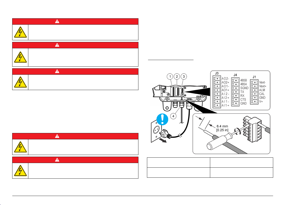
Elektrická instalace
N E B E Z P E Č Í
Nebezpečí poranění elektrickým proudem. Před jakýmikoli pracemi
na elektrickém zapojení odpojte přístroj od zdroje napájení.
N E B E Z P E Č Í
Nebezpečí poranění elektrickým proudem. Pokud se toto zařízení
používá mimo kryté prostory nebo na potenciálně vlhkých místech,
musí se k připojení zařízení k hlavnímu zdroji napájení použít vypínač
zemních poruchových proudů (GFCI/GFI).
Nebezpečí poranění elektrickým proudem. Připojení k ochrannému
zemnění (PE) je povinné.
Pro všechny elektrické přípojky kromě vstupního napájení používejte
stíněné kroucené dvojlinky. Použití nestíněných vodičů může
způsobovat vysílání vysokofrekvenčního záření a zvýšení hladiny
vnímavosti nad povolené hladiny.
Aby nedošlo k úrazu elektrickým proudem zemními proudy
v nevhodných zemnicích systémech připojte stínění pouze na konec
přístroj. Nepřipojujte vodič stínění na oba konce.
Elektrické přípojky
Nebezpečí smrtelného úrazu elektrickým proudem. Nepoužívejte
dvouvodičové připojení pro přívod elektrické energie. Pouzdro nemá
přípojku ochranného zemnění (PE).
N E B E Z P E Č Í
N E B E Z P E Č Í
Elektrické kabely připojuje přes kabelové průchodky. Dodržení krytí
skříně:
• Do kabelové průchodky nevkládejte více než jeden kabel (nebo dva
voidiče).
•
Zkontrolujte, zda zda jsou nepoužívané kabelové průchodky opatřeny
gumovými zátkami. Používejte kabelové průchodky vhodné pro daný
stupeň krytí.
Dodržujte veškeré zásady a předpisy pro zapojování kabelů. Utáhněte
kabelové průchodky tak, aby kabely spolehlivě držely.
Obr. 4 Přehled zapojení
N E B E Z P E Č Í
Nebezpečí poranění elektrickým proudem. Před jakýmikoli pracemi
na elektrickém zapojení odpojte přístroj od zdroje napájení.
Obr. 4 zobrazuje připojení vodičů a obecný postup připojení vodičů.
84 Čeština
1 Přípojky analogových
vstupů/výstupů
2 Komunikační přípojky
(RS232 a RS485)
3 Přípojky alarmů (digitální výstupy)
4 Chránič kabelů proti napínání pro
externí přípojky (4x)
Page 85

Připojení analogových výstupů (volitelné)
Na konektoru J3 jsou k dispozici dva analogové výstupy
4-20 mA (AO1 a AO2). Signál analogového výstupu je úměrný počtu/ml
v kanálu. Počet/ml na Kanále 1 je označen AO1. Počet/ml
na Kanále 2 je označen AO2.
Zařízení, do kterého se přivádí proud, připojte ke každému analogovému
výstupu pomocí vodiče 24–28 AWG. Viz Tabulka 1.
Pokud zařízení, do kterého (do kterých) se přivádí proud, mají zátěžový
rezistor 500 ohmů nebo více, připojte externí napájení (max. 40 VDC)
k pinům Vext– a Vext+ na konektoru J1, aby bylo zařízení, do kterého
se přivádí proud, napájeno dostatečným napětím.
Tabulka 1 Přípojky analogových výstupů (4-20 mA)
Pól Popis
AO2– neutrální
AO2+ kladný
AO1– neutrální
AO1+ kladný
Připojení analogového vstupu (volitelný)
Na konektoru J3 jsou k dispozici dva analogové vstupy (AI1 a AI2).
K analogovým vstupům můžete připojit pomocné přístroje (například
průtokoměry, měřiče turbidity, tlakové převodníky, měřiče pH)
a zobrazovat napětí dodávané pomocnými přístroji na displeji přístroje
(0–10 VDC). Viz Zjištění hodnot analogových vstupů na straně
Pomocný přístroj připojte ke každému analogovému vstupu pomocí
vodiče 22–24 AWG. Anebo pomocí vodiče 19 AWG, má-li vodič délku
7,62 m nebo více. Viz Tabulka 2.
Tabulka 2 Přípojky analogových vstupů (0–10 VDC)
Pól Popis
AI2– neutrální
AI2+ kladný
92.
Tabulka 2 Přípojky analogových vstupů (0–10 VDC) (pokračování)
Pól Popis
AI1– neutrální
AI1+ kladný
Připojení digitálního vstupu (volitelné)
K dispozici je jeden digitální vstup na konektoru J4. Připojte zařízení pro
monitorování průtoku k digitálnímu vstupu (pin CTS), aby se spouštěl
alarm průtoku, je-li napětí na digitálním vstupu vysoké nebo nízké,
a to v závislosti na nastavení Flow Alarm State (Stav alarmu průtoku).
Konfigurace nastavení Flow Alarm State (Stav alarmu průtoku)
a aktivace alarmu průtoku viz Konfigurace čítače částic na straně 89.
Zařízení pro monitorování průtoku připojte k pinu CTS pomocí vodiče
24-28 AWG.
Poznámka:
připojení tiskárny nebo počítače.
Digitální vstup není k dispozici, pokud používáte přípojku RS232 pro
Připojení digitálních výstupů (volitelné)
Na konektoru J1 jsou k dispozici dva digitální výstupy (ALM a CAL). Viz
Tabulka 3. Kompatibilní zařízení, například dálkový indikátor alarmu
nebo bzučák, připojte k příslušnému digitálnímu výstupu pomocí vodiče
24-48 AWG.
Pin ALM a pin CAL jsou výstupy s otevřeným uzemněným kolektorem,
které pod napětím napájejí připojení země. Dodržte specifikace
digitálního výstupu podle Technické údaje na straně 79.
Tabulka 3 Popisy digitálních výstupů
Digitální výstup Popis
Pin ALM Pod napětím, je-li aktivní alarm průtoku nebo alarm čítače.
Pin CAL Pod napětím, je-li aktivní vysoká nebo nízká kalibrační chyba.
Konfigurace alarmu průtoku a alarmu čítače viz Konfigurace
čítače částic na straně 89.
Čeština 85
Page 86

Připojení sériového zařízení (volitelné)
K dispozici je jedna přípojka RS232 na konektoru J4. Tiskárnu nebo
sériový port počítače (COM 1 nebo COM 2) můžete připojit k přípojce
RS232 a odesílat data z vyrovnávací paměti do tiskárny nebo
do počítače. Viz Odesílání protokolu dat do tiskárny nebo počítače
na straně 91.
Pokud používáte volitelný konvertor RJ-45/DB-9, seřízněte kabel
RJ-45 a potom oddělte a určete vodiče. Viz Obr. 5. Viz
se schématem zapojení vodičů RS232.
Poznámka: Přípojka RS232 není dosputná, pokud používáte digitální vstup (pin
CTS).
Obr. 5 Vodiče konvertoru RJ-45/DB-9
1 Do počítače nebo
tiskárny
2 Konvertor
RJ-45/DB-9 (SA000070-01)
Tabulka 4 Připojení rozhraní RS232
Pin DB-9 Pin RJ-45 Pin J4
Pin 2 RX Pin 3 TX
Pin 3 TX Pin 4 RX
Tabulka 4
3 Kabel RJ-45 (dodává
uživatel)
Tabulka 4 Připojení rozhraní RS232 (pokračování)
Pin DB-9 Pin RJ-45 Pin J4
Pin 4 DTR Pin 5 CTS
Pin 5 GND Pin 8 GND
Přívod napájení do externího zařízení (volitelné)
Pro napájení externího zařízení je k dispozici +5 VDC nebo +12 VDC
na konektoru JP1. +5 VDC se přivádí, je-li můstek mezi pinem +5V
a pinem 2 konektoru JP1. +12 VDC se přivádí, je-li můstek mezi pinem
Vps a pinem 2 konektoru JP1.
Poznámka: Pin V+ a pin GND na konektoru J1 jsou určeny pouze pro servisní
účely.
Připojení jednotek do sítě (volitelné)
Několik jednotek lze spojit do sítě. Pro spojení jednotek použijte přípojku
RS485 na každé jednotce a kroucený stíněný párový vodič 19 AWG.
Poznámky:
• Do jedné sítě RS485 lze připojit nejvýše 32 jednotek.
•
Hostitelský počítač musí mít software pro sběr dat.
• Komunikačním protokolem je Modbus. Prostudujte si dokumentaci
protokolu WPC Modbus na webové stránce výrobce.
1. Na první jednotce:
a. Protáhněte vstupující kabel z konvertoru RS232/RS485 skrz
kabelový chránič proti napínání.
b. Protáhněte vycházející kabel skrz kabelový chránič proti
napínání.
c. Připojte vodiče vstupujícího a vycházejícího kabelu ke konektoru
J4. Viz Tabulka 5.
2. Na druhé jednotce:
a. Protáhněte vstupující kabel z první jednotky skrz kabelový
chránič proti napínání.
b. Protáhněte vycházející kabel skrz kabelový chránič proti
napínání.
86 Čeština
Page 87

c. Připojte vodiče příchozího a odchozího kabelu ke konektoru J4.
Viz Tabulka 5.
3. Opakujte krok 2 pro třetí a zbývající jednotky, dokud nevytvoříte
příchozí a odchozí přípojky pro všechny jednotky. Poslední jednotka
nebude mít vycházející kabel.
Poznámka: V síťové instalaci je vycházející kabel předchozí jednotky vždy
příchozím kabelem další jednotky.
4. Na poslední jednotce nainstalujte můstek přes JP2. Na ostatních
jednotkách nesmíte můstek přes JP2 instalovat.
5. Nastavte volbu MODE (Režim) na N (síťový režim). Volba
Date/MODE (Datum/Režim) viz Konfigurace čítače částic
na straně 89.
6. Každé jednotce přiřaďte unikátní adresu. Volba Unit ID (ID jednotky)
viz Konfigurace čítače částic na straně 89.
Tabulka 5 Připojení rozhraní RS485
Vodič Pin J4
– RS485A
+ RS485B
Stínění SGND
Potrubí
Zapojení armatur přístroje
Potřebné vybavení:
• Matné hadičky, vnější průměr 6 mm
•
Dvě 6mm objímky
Vybírejte hadičky podle nejhorších podmínek prostředí (například
teplotní rozsah, expozice slunečnímu záření, kontaminace vzduchu)
a nejvyššího potenciálního vstupního tlaku (max. 120 psi).
1. Odmontujte hadičky od přípojky vedení vzorku a přípojky
vypouštěcího vedení a zlikvidujte je. Nepoužívejte znovu hadičky pro
vstup vzorku a výstup vzorku.
2. Připojte vedení vzorku k přípojce vedení vzorku na tělese přístroje.
Viz Obr. 6.
3. Připojte vypouštěcí vedení k přípojce vypouštěcího vedení na tělese
přístroje. Viz Obr. 6.
4. V případě potřeby nainstalujte Y filtr na přívod vzorku, aby velké
částice nepronikaly do snímače a neucpaly ho.
5. Nainstalujte ruční uzavírací ventil na přívod vzorku, aby bylo možné
v případě potřeby přívod vzorku uzavřít.
Obr. 6 Zapojení armatur přístroje
1 Fitink na vstup vzorku 3 Plastová matice
2 Fitink na výstup vzorku 4 Objímka, 6 mm
Pokyny pro přívodní hadičku vzorku
Pro co nejlepší funkci přístroje zvolte bod odběru vzorku, který bude
dostatečně kvalitní a reprezentativní. Vzorek musí být reprezentativní
v celém systému.
Prevence chybných měření:
• Odebírejte vzorky v bodech, které jsou dostatečně vzdálené od bodů,
kde se do procesního proudu přidávají chemické látky.
Čeština 87
Page 88

• Zajistěte, aby vzorky byly dostatečně promíchány.
• Dbejte, aby proběhlo úplné dokončení chemických reakcí.
Připojení vzorkovacího proudu
Nainstalujte vedení vzorku do větší procesní trubky, aby
se minimalizoval vliv vzduchových bublin nebo usazování na dně
potrubí. Ideální je odběr vzorku ze středu potrubí.
Obr. 7
zobrazuje příklady dobrých a špatných metod instalace odběru
vzorku z procesního potrubí.
Přívod vzorku musí být co nejkratší, aby se minimalizovalo zpoždění
analýzy. V dlouhém vedení vzorku se může hromadit usazenina.
Obr. 7 Metody vzorkování
1 Vzduch 2 Průtok vzorku
Spuštění
Zapnutí napájení
1. Připojte napájecí kabel k elektrické zásuvce se zemněním.
2. Otevřete dvířka pouzdra. Uvolněte všechny čtyři šrouby, které drží
dvířka pouzdra.
3. Přepněte vypínač do polohy ON (zapnuto).
4. Zavřete dvířka pouzdra. Utáhněte všechny čtyři šrouby, které drží
dvířka pouzdra.
Uživatelské rozhraní a navigační tlačítka
Uživatelské rozhraní
Obr. 8 zobrazuje displej, klávesnici a indikační kontrolky. Popis kláves
viz Tabulka 6. Popis indikačních kontrolek viz Tabulka 7.
Obr. 8 Uživatelské rozhraní
1 Kontrolka alarmu 5 Kontrolka napájení
2 Klávesa F1 6 Tlačítko ENTER
3 Klávesa START/STOP 7 Klávesa F2
4 Displej 8 Kontrolka snímače
88 Čeština
Page 89

Tabulka 6 Popis kláves
Klávesa Charakteristika
START/STOP Spustí nebo zastaví počítání částic
F1 Používá se pro procházení nabídek a změny nastavení
F2 Používá se pro procházení nabídek a změny nastavení
ENTER (Zadat) Potvrzení, zadání nebo výběr. Stisknutím uložíte aktuálnní stav
čítače do vyrovnávací paměti (pouze samostatný režim).
Tabulka 7 Popisy indikačních kontrolek
Kontrolka Barva Popis
Napájení Zelená Přístroj je napájen a spínač napájení je zapnutý.
Poplach Červená Trvale svítí—Je aktivní alarm sítě.
Bliká—Je aktivní alarm čítače nebo alarm průtoku.
Viz Řešení problémů na straně 95.
Senzor Žlutá Trvale svítí—Je aktivní vysoká kalibrační chyba.
Bliká—Je aktivní nízká kalibrační chyba.
Viz Řešení problémů na straně 95.
Popis zobrazení
Obr. 9 zobrazuje informace zobrazené na displeji.
Vyskytne-li se chyba kalibrace nebo alarm průtoku, zobrazí se na displeji
chybové hlášení. Viz Hlášení o poruchách na straně 95.
Obr. 9 Obrazovka čítače
1 Velikost částic monitorovaná
na Kanálu 2
2 Velikost částic monitorovaná
na Kanálu 1
3 Počet částic monitorovaný
na Kanálu 1
4 Počet částic monitorovaný
na Kanálu 2
5 Funkce softwarových kláves
F1 a F2
Provoz
Konfigurace čítače částic
Čítač částic lze konfigurovat pro samostatný provoz nebo síťový provoz.
V síťovém režimu se nastavení vyrovnávací paměti dat, tisku a Velikost
kanálu 2 mění pomocí síťového softwaru, takže tato nastavení nejsou
dostupná na displeji přístroje.
1. Stiskněte F1, vyberte volbu a poté stiskněte ENTER. Zobrazí
se aktuální nastavení.
Čeština 89
Page 90

Pouze samostatný režim
Volba Popis
Intervals (Intervaly) BUF (Vyrovnávací paměť)—Nastaví interval
vyrovnávací paměti (protokol dat). Volby: OFF
(Vypnuto, neaktivní), 30 sekund, 1, 5, 10, 30 nebo
60 minut.
Na konci každého intervalu vyrovnávací paměti
se do vyrovnávací paměti uloží datum, čas, stav
snímače a hodnota čítače. Do vyrovnávací paměti
se vejde nejvýše 100 záznamů. Jakmile
se vyrovnávací paměť zaplní, ukládají se nová
data namísto nejstarších dat.
Poznámka: Je-li připojena sériová tiskárna, budou se data
při každém uložení do vyrovnávací paměti také odesílat
do tiskárny.
SCRL (Posouvání)—Nastaví interval posouvání.
Volby: OFF (Vypnuto, neaktivní), 30 sekund, 1, 5,
10, 30 nebo 60 minut.
Na konci každého intervalu posouvání začne
přístroj monitorovat další kalibrovanou velikost
částic na Kanálu 2. Je-li volba neaktivní, velikost
částic monitorovaných na Kanále 2 je nastavení
Velikost kanálu 2.
Poznámka: Je-li interval vyrovnávací paměti delší než
interval posouvání, neuloží se do vyrovnávací paměti
žádná data.
Buff Count/Print
Buff/Download (Čítač
vyrovnávací
paměti/Vyrovnávací
Viz Odesílání protokolu dat do tiskárny nebo
počítače na straně 91. Hodnota Buff Count
(Čítač vyrovnávací paměti) zobrazuje počet
záznamů ve vyrovnávací paměti (protokol dat).
paměť
tisku/Stahování)
Volba Popis
Buff Count/View
Buffer/ Delete Buffer
(Čítač vyrovnávací
paměti/Vyrovnávací
Viz Zobrazení nebo smazání vyrovnávací paměti
(protokol dat) na straně 92. Hodnota Buff Count
(Čítač vyrovnávací paměti) zobrazuje počet
záznamů ve vyrovnávací paměti (protokol dat).
paměť tisku/Smazat
vyrovnávací paměť)
Count Alarms (Alarmy
čítače)
Nastaví minimální počet částic, který spustí alarm
čítače na Kanálu 1 a Kanálu 2. Chcete-li volbu
deaktivovat, nastavte hodnotu 0.
A1—Limit čítače pro Kanál 1
A2—Limit čítače pro Kanál 2
Stiskněte INC a změňte vybranou číslici.
Stisknutím šipky RIGHT (Doprava) vyberete další
číslici.
Pouze síťový režim
Volba Popis
ID jednotky = 1 Nastaví jedinečnou adresu pro přístroj. Volby: 1 až 247.
Adresu 0 nelze použít. Tato volba se zobrazuje, pouze je-li
volba MODE (Režim) nastavena na N (síťový režim).
90 Čeština
Page 91

Samostatný a síťový režim
Volba Popis
Analog Count Out/Upper
1/Lower 1 (Analogový čítač
mimo/horní 1/dolní 1)
Analog Count Out/Upper
2/Lower 2 (Analogový čítač
mimo/horní 2/dolní 2)
Channel 2 Size (Velikost
kanálu 2)
Flow Rate/Flow Alarm
(Rychlost průtoku/Alarm
průtoku)
Flow Alarm State Active
(Aktivní stav alarmu
průtoku)
Input 1/Input
2 (Vstup 1/Vstup 2)
Nastaví limity čítače (rozsah) pro analogový
výstup (4–20 mA) pro Kanál 1.
UL1—Horní limit čítače, který odpovídá
výstupnímu signálu 20 mA
LL1—Dolní limit čítače, který odpovídá
výstupnímu signálu 4 mA
Nastaví limity čítače (rozsah) pro analogový
výstup (4–20 mA) pro Kanál 2.
UL2—Horní limit čítače, který odpovídá
výstupnímu signálu 20 mA
LL2—Dolní limit čítače, který odpovídá
výstupnímu signálu 4 mA
Pomocí šipkových kláves UP (Nahoru)
a DOWON (Dolů) nastavíte velikost částic,
které se budou monitorovat na Kanálu 2, je-li
interval posouvání nastaven na OFF
(Vypnuto).
RATE (Rychlost)—Zadejte rychlost průtoku
ALM (Alarm)—Aktivuje (ZAPNUTO) nebo
deaktivuje (VYPNUTO) alarm průtoku. Je-li
dostupné zařízení pro monitorování průtoku,
monitoruje se alarm průtoku na digitálním
vstupu (pin CTS).
Nastaví alarm průtoku na spuštění při
vysokém nebo nízkém napěťovém vstupu
na pinu CTS v závislosti na aktivním stavu
zařízení pro alarm průtoku. Volby:
HI (Vysoký) nebo LO (Nízký).
Je-li aktivní stav alarmu průtoku nastaven
na HI (Vysoký), bude vysoký napěťový vstup
(> 2,5 VDC) na pinu CTS ze zařízení pro
alarm průtoku spouštět alarm průtoku
a 0 V bude identifikovat normální průtok.
Viz Zjištění hodnot analogových vstupů
na straně 92.
Volba Popis
Contrast/Beep
(Kontrast/Pípnutí)
Date/MODE (Datum/Režim) Date (Datum)—Pro zadání data a času
CON (Kontrast)—Nastaví kontrast
BEP (Pípnutí)—Aktivuje (ZAPNUTO) nebo
deaktivuje (VYPNUTO) slyšitelné pípnutí.
(24hodinový formát)
MODE (Režim)—Nastaví režim. Volby:
S (samostatný režim) nebo N (síťový režim)
Odesílání protokolu dat do tiskárny nebo počítače
Data ve vyrovnávací paměti (protokol dat) lze odesílat do připojené
tiskárny nebo počítače. Viz Připojení sériového zařízení (volitelné)
na straně 86.
1. Nastavte sériový port tiskárny nebo počítače na tyto hodnoty:
9600 baudů, 8 data, potlačená parita, 1 stopbit a bez řízení toku dat.
Poznámka:
pokud nejsou schopny přijímat souvisle data rychlostí 9600 baudů.
2. Stiskněte F1, dokud se nezobrazí „Buff Count/Print Buff/Download“
(Čítač vyrovnávací paměti/Vyrovnávací paměť tisku/Stahování),
a poté stiskněte ENTER.
3. Vyberte některou z možností. Okno opustíte stisknutím ENTER.
Volba Popis
PRT Odesílá data z vyrovnávací paměti (protokol dat) do připojené
DNLD Odesílá data z vyrovnávací paměti (protokol dat) do připojeného
Tabulka 11 Status codes (binary) (Stavové kódy, binární)
Kód Popis
1 Chyba snímače
2 Alarm čítače K1
Počítač nebo tiskárna nebudou přijímat kompletní přenášená data,
tiskárny nebo na displej terminálu. Nejstarší data se odešlou
nejdříve. Stavové kódy snímače viz Tabulka 11.
počítače. Stavové kódy snímače viz Tabulka 11.
Čeština 91
Page 92

Tabulka 11 Status codes (binary) (Stavové kódy, binární)
(pokračování)
Kód Popis
3 Chyba snímače a alarm čítače K1
4 Alarm čítače K2
5 Chyba snímače a alarm čítače K2
6 Alarmy čítače K1 a K2
7 Chyba snímače, alarm čítače K1 a alarm čítače K2
8 Alarm průtoku nebo alarm digitálního vstupu
Zobrazení nebo smazání vyrovnávací paměti (protokol dat)
1. Stiskněte F1, dokud se nezobrazí „Buff Count/View Buff/Delete Buff“
(Čítač vyrovnávací paměti/Vyrovnávací paměť tisku/Smazat
vyrovnávací paměť), a poté stiskněte ENTER.
2. Vyberte některou z možností. Okno opustíte stisknutím ENTER.
Volba Popis
VIEW
(Zobrazit)
DEL (Smazat) Smaže všechna data ve vyrovnávací paměti (protokol dat).
Zobrazí data ve vyrovnávací paměti (protokol dat).
Nejnovější data se zobrazí jako první. Zobrazené stavové
kódy:
A—Jeden z kanálů překročil hodnotu nastavení alarmu
čítače pro daný kanál.
S—Pravděpodobně bude nutné vyčistit průtočnou celu
snímače.
Pro postup zpět stiskněte BAK (Zpět). Pro postup dopředu
stiskněte NXT (Další). Okno opustíte stisknutím ENTER.
Stisknutím tlačítka YES (Ano) potvrdíte smazání nebo
tlačítkem NO (Ne) ukončíte akci.
Zjištění hodnot analogových vstupů
Stiskněte F1, dokud se nezobrazí „Input 1/Input 2“ (Vstup 1/Vstup 2),
a poté stiskněte ENTER. Zobrazí se napětí dodávané pomocnými
přístroji připojenými ke každému analogovému vstupu. Tyto informace
se v samostatném režimu neukládají ve vyrovnávací paměti, lze je však
zobrazit v síťovém režimu.
Kalibrace
Uživatel nemůže kalibrovat přístroj. Chcete-li provést kalibraci
obraťte se na výrobce. Informace o datu povinné kalibrace zjistíte
ze štítku na přístroji.
přístroj
Údržba
V A R O V Á N Í
Různá nebezpečí. Práce uvedené v tomto oddíle dokumentu smí
provádět pouze dostatečně kvalifikovaný personál.
Plán údržby
Tabulka 12 zobrazuje doporučený harmonogram úloh údržby.
Požadavky provozující organizace a provozní podmínky si mohou vynutit
častější provádění některých úloh.
Tabulka 12 Plán údržby
Úkony údržby 1 rok Podle potřeby
Kalibrace na straně 92 X
Čištění přístroje
Čištění průtočné cely snímače na straně 93 X
Výměna balíčku pohlcovače vlhkosti na straně 93 X
Výměna pojistky na straně 94 X
1
Vyžadováno z důvodu shody s normami JIS B 9925-1997
na straně 93 X
1
92 Čeština
Page 93

Čištění přístroje
Vyčistěte vnější povrch přístroje vlhkým hadříkem a jemným mýdlovým
roztokem a poté přístroj otřete dosucha.
Čištění průtočné cely snímače
U P O Z O R N Ě N Í
Je-li průtočná cela suchá, nezasunujte čisticí kartáč do přípojky hadičky vzorku,
jinak se může poškodit průtočná cela snímače.
Pravidelně provádějte čištění průtočné cely snímače. Dále nebyl-li
přístroj delší dobu používán, vyčistěte před použitím průtočnou celu
snímače.
Položky k odběru:
• Výrobcem dodaný čisticí kartáč
•
Čistá voda
1. Otevřete dvířka pouzdra. Uvolněte všechny čtyři šrouby, které drží
dvířka pouzdra.
2. Přepněte vypínač do polohy vypnuto.
3. Zastavte přítok vody do přístroje.
4. Vyjměte vedení vzorku a vypouštěcí vedení z kompresní přípojky.
5. Připojte vedení vzorku ke kompresní přípojce na horní straně
sestavy snímače.
6. Pusťte přítok vody do přístroje. Po 30 sekundách přítok zastavte.
7. Vyjměte přívod vzorku z kompresní přípojky.
8. Vyčistěte průtočnou celu snímače.
a. Nalijte čistou vodu do kompresní přípojky na horní straně sestavy
snímače. Voda vyteče z kompresní přípojky vedení vzorku.
b. Zasuňte čisticí kartáč do kompresní přípojky. Opatrně pohybujte
kartáčem dvakrát nebo třikrát nahoru a dolů. Viz Obr. 10.
c. Nalijte čistou vodu do kompresní přípojky na horní straně sestavy
snímače. Tím se vypláchne veškerý materiál uvolněný kartáčem.
d. Polévejte čisticí kartáč čistou vodou, aby se vypláchl veškerý
materiál.
9. Připojte hadičky vedení vzorku a vypouštěcí vedení. Viz Zapojení
armatur přístroje na straně 87.
10. Spusťte přítok vody do přístroje.
11. Přepněte vypínač do polohy ON (zapnuto).
12. Zavřete dvířka pouzdra. Utáhněte všechny čtyři šrouby, které drží
dvířka pouzdra.
Obr. 10 Čištění průtočné cely snímače
Výměna balíčku pohlcovače vlhkosti
Balíček pohlcovače vlhkosti vyměňte, jakmile se modrá barva krystalů
v balíčku změní na růžovou. Umístění balíčku pohlcovače vlhkosti viz
Obr. 1 na straně 82.
Balíček pohlcovače vlhkosti je nutné používat na prevenci vytváření
vlhkosti v pouzdru přístroje. Tím se brání korozi citlivých elektrických
přípojek a zlepšuje se ochrana před hromaděním kondenzátu v sestavě
snímače.
Potřebné vybavení:
• Balíček pohlcovače vlhkosti
Adhezivní pás suchého zipu
•
Čeština 93
Page 94

1. Otevřete dvířka pouzdra. Uvolněte všechny čtyři šrouby, které drží
dvířka pouzdra.
2. Přepněte vypínač do polohy vypnuto.
3. Otevřete elektroinstalační přístupový panel. Otočte oba ¼otáčkové
roznýtovné šrouby pouze o ¼ otáčky.
4. Vyměňte balíček pohlcovače vlhkosti.
a. Vytáhněte použitý balíček pohlcovače vlhkosti ze suchého zipu
na zadním panelu a zlikvidujte jej.
b. Nový balíček pohlcovače vlhkosti přetáhněte adhezivním suchým
zipem.
c. Zatlačte balíček pohlcovače vlhkosti do suchého zipu na zadním
panelu.
5. Zavřete a připevněte elektroinstalační přístupový panel pomocí obou
¼otáčkových šroubů.
6. Přepněte vypínač do polohy ON (zapnuto).
7. Zavřete dvířka pouzdra. Utáhněte všechny čtyři šrouby, které drží
dvířka pouzdra.
Výměna pojistky
N E B E Z P E Č Í
Nebezpečí požáru. Používejte náhradní pojistky stejného typu
a se stejnou proudovou charakteristikou.
N E B E Z P E Č Í
Nebezpečí poranění elektrickým proudem. Před započetím údržby
odpojte napájení přístroje a reléových připojení.
2. Přepněte vypínač do polohy vypnuto.
3. Otevřete elektroinstalační přístupový panel. Otočte oba ¼otáčkové
roznýtovné šrouby pouze o ¼ otáčky.
4. Vyměňte pojistku. Viz ilustrované kroky v Obr. 11.
5. Sestavte přístroj. Kroky zobrazené na Obr. 11 proveďte v obráceném
pořadí.
6. Zavřete a připevněte elektroinstalační přístupový panel pomocí obou
¼otáčkových šroubů.
7. Přepněte vypínač do polohy ON (zapnuto).
8. Zavřete dvířka pouzdra. Utáhněte všechny čtyři šrouby, které drží
dvířka pouzdra.
Obr. 11 Výměna pojistky
Položky k odběru:
• Pojistka, 5 x 20 mm T, 0,500 mA, 250 V
• Šroubovák Phillips
1. Otevřete dvířka pouzdra. Uvolněte všechny čtyři šrouby, které drží
dvířka pouzdra.
94 Čeština
Page 95

Řešení problémů
Hlášení o poruchách
Problém Možná příčina Řešení
Kontrolka POWER
(Napájení)
se nerozsvítí
Svítí kontrolka
ALARM
Kontrolka ALARM
bliká
Svítí kontrolka
SENSOR (Snímač)
Bliká kontrolka
SENSOR (Snímač)
Dva nebo více
přístrojů nereaguje
na monitorovací
software
Přístroj nemá napájení
nebo je spínač napájení
vypnutý.
Je aktivní alarm sítě.
Poznámka: Alarm sítě
se aktivuje a deaktivuje pouze
síťovým softwarem.
Je aktivní alarm čítače
(pouze u samostatných
přístrojů) nebo alarm
průtoku.
Poznámka: Je-li aktivní alarm
čítače, bliká na displeji kontrolka
ALARM a kanál s alarmem.
Je aktivní vysoká kalibrační
chyba. Snímač
je kontaminován nebo
laserová dioda ztrácí
výkon.
Je aktivní nízká kalibrační
chyba. Fotodioda
je saturovaná a potřebuje
vyčistit, seřídit nebo
vyměnit.
Dva nebo více přístrojů má
stejnou adresu. Přístroje
se stejnou adresou
nereagují na monitorovací
software.
Zkontrolujte, zda je spínač
napájení zapnutý.
Zkotnrolujte přívod napájení
do přístroje.
Konfigurace nastavení
alarmu čítače viz
Konfigurace čítače částic
na straně 89.
Vyčistěte průtočnou celu.
Viz Čištění průtočné cely
snímače na straně 93.
Pokud vysoká kalibrační
chyba přetrvává, obraťte
se na technickou podporu.
Vyčistěte průtočnou celu.
Viz Čištění průtočné cely
snímače na straně 93.
Pokud nízká kalibrační
chyba přetrvává, obraťte
se na technickou podporu.
Vypněte monitorovací
software a přístrojům, které
mají stejnou adresu,
přiřaďte jedinečnou adresu.
Volba Unit ID (ID jednotky)
viz Konfigurace čítače
částic na straně 89.
Hlášení Možná příčina Řešení
CAL Je aktivní chyba vysoké
FLOW
—
(Průtok)
nebo nízké kalibrace.
Externí zařízení pro
monitorování průtoku
spustilo alarm průtoku.
Vyčistěte průtočnou celu. Viz Čištění
průtočné cely snímače na straně 93.
Pokud chyba kalibrace přetrvává,
obraťte se na technickou podporu.
Viz Připojení digitálního vstupu
(volitelné) na straně 85.
Náhradní díly a příslušenství
V A R O V Á N Í
Nebezpečí poranění osob. Použití neschválených součástí může
způsobit poranění osob, poškození nebo nesprávné fungování
přístroje či vybavení. Náhradní díly v tomto oddíle jsou schváleny
výrobcem.
Poznámka: Čísla produktů a položek se mohou v různých regionech prodeje lišit.
Pokud potřebujete kontaktní infomace, obraťte se na příslušného dodavatele nebo
se podívejte na webové stránky společnosti.
Náhradní díly
Popis Položka č.
Objímka, 6 mm, adaptér na 0,25 palce. kompresní přípojka MP000147-01
Sada dvou čisticích kartáčů 1µm, pro WPC-22 SA000120-02
Sada čisticích kartáčů se dvěma 2µm čisticími kartáči, pro
WPC-21
Sada pohlcovače vlhkosti se dvěma balíčky pohlcovače
vlhkosti a dvěma adhezivními štítky na suchý zip
Pojistka, 5 x 20 mm T, 0,500 mA, 250 V 500-150-0050
Napájecí kabel, 230 VAC 510667
SA000120-01
SA000180-01
Čeština 95
Page 96

Náhradní díly (pokračování)
Popis Položka č.
Chránič kabelů proti napínání pro napájecí kabel VP752401
Chránič kabelů proti napínání pro externí přípojky 570-730-2212
Příslušenství
Popis Položka č.
Software AQUARIUS CS200011
Konvertor RJ-45/DB-9 SA000070-01
USB konvertor pro RS485/RS422 5920400
Hadičky, matné, 0,25 palce vnější průměr, černý PTFE VP792021
Přepadový regulátor průtoku pro nastavení průtoku 2081335-1
96 Čeština
Page 97

Page 98

HACH COMPANY World Headquarters
P.O. Box 389, Loveland, CO 80539-0389 U.S.A.
Tel. (970) 669-3050
(800) 227-4224 (U.S.A. only)
Fax (970) 669-2932
orders@hach.com
www.hach.com
©
Hach Company/Hach Lange GmbH, 2013. All rights reserved. Printed in Germany.
HACH LANGE GMBH
Willstätterstraße 11
D-40549 Düsseldorf, Germany
Tel. +49 (0) 2 11 52 88-320
Fax +49 (0) 2 11 52 88-210
info@hach-lange.de
www.hach-lange.de
HACH LANGE Sàrl
6, route de Compois
1222 Vésenaz
SWITZERLAND
Tel. +41 22 594 6400
Fax +41 22 594 6499
 Loading...