

Page 1

DOC023.52.03230
UVAS sc
USER MANUAL
08/2012, Edition 3A
© HACH LANGE, 2004, 2005, 2012. All rights reserved. Printed in Germany
Page 2

Page 3

Table of Contents
Section 1 Specifications ............................................................................................................................................... 5
Section 2 General information ..................................................................................................................................... 7
2.1 Safety information...................................................................................................................................................... 7
2.1.1 Hazard information in this manual ................................................................................................................... 7
2.1.2 Warning labels ................................................................................................................................................. 7
2.2 Applications ............................................................................................................................................................... 8
2.3 Measuring principle ................................................................................................................................................... 8
Section 3 Installation....................................................................................................................................................11
3.1 Installation overview ................................................................................................................................................ 11
3.2 Sensor ..................................................................................................................................................................... 12
3.3 Attaching the Sensorcable....................................................................................................................................... 15
3.4 Wiring safety information......................................................................................................................................... 15
3.4.1 Sensor connection and wiring........................................................................................................................ 16
Section 4 Operation..................................................................................................................................................... 17
4.1 sc controller operation ............................................................................................................................................. 17
4.2 Sensor setup ........................................................................................................................................................... 17
4.3 Sensor data logger .................................................................................................................................................. 17
4.4 Menu structure......................................................................................................................................................... 18
4.4.1 SENSOR STATUS......................................................................................................................................... 18
4.4.2 SENSOR setup .............................................................................................................................................. 18
4.5 Calibration ............................................................................................................................................................... 22
4.5.1 Verifying ......................................................................................................................................................... 22
4.5.2 Zero point calibration ..................................................................................................................................... 23
4.5.3 1 point calibration........................................................................................................................................... 23
4.6 Adjusting measured values ..................................................................................................................................... 24
4.6.1 Zero point adjustment .................................................................................................................................... 24
4.6.2 Setting factor.................................................................................................................................................. 24
4.7 Conversion into other total parameters ................................................................................................................... 25
Section 5 Maintenance ................................................................................................................................................ 27
5.1 Maintenance schedule............................................................................................................................................. 27
5.2 Cleaning measuring path......................................................................................................................................... 28
5.3 Changing wiper profile............................................................................................................................................. 29
5.4 Seal change (bypass version) ................................................................................................................................. 30
5.4.1 UVAS plus sc ................................................................................................................................................ 30
Section 6 Troubleshooting ......................................................................................................................................... 31
6.1 Error messages ....................................................................................................................................................... 31
6.2 Warnings ................................................................................................................................................................. 31
Section 7 Replacement Parts ..................................................................................................................................... 33
Section 8 Warranty and liability ................................................................................................................................. 35
Section 9 Contact ....................................................................................................................................................... 37
Appendix A ModBUS Register Information
.............................................................................................................. 39
3
Page 4

Table of Contents
4
Page 5
Section 1 Specifications
Specifications are subject to change without notice.
Table 1 UVAS plus sc tank sensors
UVAS plus sc
Measuring technique UV absorption measurement (2-beam technique), reagent-free
Measuring method SAC 254 in accordance with DIN 38404 C3
Measuring path 1, 2, 5 and 50 mm
0.01-60 m
0.1-600 m–1 (5 mm)
Measuring range
Can be calibrated to the total parameter COD depending on the application
Compensation 550 nm
Measuring interval (> min) >1 min
Cable length
Optional extension cables available in 5, 10, 15, 20, 30, 50 m
Total maximum length: 60 m (196 ft)
0-1500 m
2-3000 m–1 (1 mm)
10 m (33 ft) standard
–1
(50 mm)
–1
(2 mm)
Control function PID, time control, 2-point controller (with sc 100)
Probe pressure limit max. 0.5 bar
Ambient temperature +2 °C to +40 °C
Dimensions D × L Approx. 70 mm x 333 mm
Mass approx. 3.6 kg
Inspection interval 6 months
User maintenance 1 h / month, typical
Table 2 UVAS plus sc bypass sensors
UVAS plus sc (in the bypass)
Measuring path 2, 5 and 50 mm
0.01–60 m
Measuring range
With NO
Cable length
Sample flow rate At least 0.5 L/h sample
-N standard solutions
3
Can be calibrated to the total parameter COD depending on the application
Optional extension cables available in 5, 10, 15, 20, 30, 50 m
Total maximum length: 60 m (196 ft)
0.1–600 m
0–1500 m-1 (2 mm)
10 m (33 ft) standard
-1
(50 mm)
-1
(5 mm)
Pressure limit max. 0.5 bar
Sample connection Hose ID 4 mm / OD 6 mm
Sample temperature +2 °C to +40 °C
Dimensions see Figure 4, page 14
5
Page 6

Specifications
Component Material
Probe
probehousing
wiper axis
fitting
profile joist 2 mm
wiperarm 5 mm / 50 mm
Wiper Profile
measuring window
seal for housing
seal for fitting
probe cable
Leverage
probe adapter
leverage
Bypass
measuring cell
seals
fittings
tube
Table 3 UVAS plus sc sensor-material
stainless steel 1.4571
stainless steel 1.4571
stainless steel 1.4305
stainless steel 1.4310
stainless steel 1.4581
silicone
SUPRASIL (silica glass)
silicone
PVDF
SEMOFLEX (PUR)
stainless steel 1.4308
stainless steel 1.4301
PVC
EPDM
PVDF
PVC
6
Page 7
Section 2 General information
2.1 Safety information
Please read this entire manual before unpacking, setting up, or operating this
equipment. Pay attention to all danger and caution statements. Failure to do so
could result in serious injury to the operator or damage to the equipment.
To prevent any impairment of the instrument's safety features, it must not be used
or installed in any manner other than that specified in this manual.
DANGER
Do not use the probe in hazardous area.
2.1.1 Hazard information in this manual
DANGER
Indicates a potentially or imminently hazardous situation which, if not avoided, will result
in death or serious injury.
2.1.2 Warning labels
This symbol, if noted on the instrument, references the user manual for operation and/or safety information.
WARNING
Indicates a potentially or imminently hazardous situation which, if not avoided, could
result in death or serious injury.
CAUTION
Indicates a potentially hazardous situation that may result in minor or moderate injury.
NOTICE
Indicates a situation which, if not avoided, may cause damage to the instrument.
Information that requires special emphasis.
Note: Information that supplements points in the main text.
Read all labels and notices attached to the equipment. Personal injury or damage
to the equipment could occur if they are not observed. Any symbol on the
equipment will appear along with a caution statement in the manual.
This symbol, when noted on a product enclosure or barrier, indicates that a risk of electrical shock and/or
electrocution exists.
This symbol may appear on the product and indicates the need for protective eye wear.
7
Page 8
General information
35 cm
für den
Ausbau
der Sonde
freilassen!
1
3
4
2
Substance groups measured
1. COD 3. SAC
2. BOD 4. TOC
This symbol may appear on the product and identifies the connection point for the protective ground.
When this symbol appears on the product, it identifies the location of a fuse or a current limiter.
Electrical equipment marked with this symbol may not be disposed of in European domestic or public disposal
systems after 12 August 2005. In conformity with European local and national regulations (EU Directive
2002/96/EC), European electrical equipment users must now return old or end-of life equipment to the
manufacturer for disposal at no charge to the user.
Note: For return for recycling, please contact the equipment manufacturer or supplier for instructions on how
to return end-of-life equipment, manufacturer-supplied electrical accessories, and all auxiliary items for proper
disposal.
2.2 Applications
UVAS plus sc:
immersed directly in the medium, without pumping or preparation of a sample, the
sensor measures the content of dissolved organic compounds in activated sludge
tanks in municipal sewage treatment plants, surface water, untreated water and
treated drinking water. The system can also be used for checking the outlet of
waste water treatment plants.
2.3 Measuring principle
Bypass accessories for UVAS plus sc:
the through-flow variant of the high-precision UVAS plus sc sensor is used
wherever direct measurement in the medium is not possible for constructionrelated reasons or the medium load makes it necessary to measure a filtered
sample (very high TS contents, sewage treatment plant inlet, waste dump
seepage,...).
NOTICE
Any use other than use in accordance with requirements defined in the user manual
leads to the loss of the warranty claims and can lead to personal injury and property
damage, for which the manufacturer assumes no liability.
Organic compounds dissolved in water in general absorb UV light, for this reason
the measurement of UV absorption represents an independent total parameter for
dissolved organic substance water load. In drinking water treatment this method
of determination of the quality of water without chemicals using laboratory
photometers and filtered samples has a long tradition.
DIN 38402 C2 stipulates for the measurement of the UV absorption, the
measuring wavelength of 254 nm and characterises the measured value for a
filtered sample as a spectral absorption coefficient at 254 nm (SAC254 for short),
which is to be converted to extinctions per metre. In this way straightforward
comparability of the measured results from photometers with different cuvette
intensities is achieved and the units 1/m or m
–1
are obtained.
8
The UVAS immersed probe comprises a multiple beam absorption photometer
with effective turbidity compensation. The related controller controls the process
of the measurement using a flash lamp photometer, the mechanical cleaning of
the measuring window by a wiper, and also displays the measured values as
SAC254 in 1/m.
For other total parameters such as COD or TOC etc. there is a correlation for the
SAC254 of the same quality as, e.g., between COD and TOC. Very high
Page 9

General information
availability of measured values, minimum investment, minimum effort for
installation and maintenance or upkeep are therefore often key reasons for the
decision in favour of the UVAS sensor if an online measurement is to be used for
a total parameter.
For media containing solids, the SAC measurement with UVAS should always be
supplemented with a solids or turbidity measurement (SOLITAX sc,
ULTRATURB sc).
The maintenance effort for the user is minimal and is limited to a straightforward
inspection that, depending on the medium, is due at the most weekly.
9
Page 10

General information
10
Page 11
Section 3 Installation
3.1 Installation overview
Installation of this system may only be carried out by qualified experts in accordance
with all local safety regulations. See the mounting instruction sheet for more information.
Figure 1 Installation example with optional accessories
CAUTION
11
Page 12
Installation
3.2 Sensor
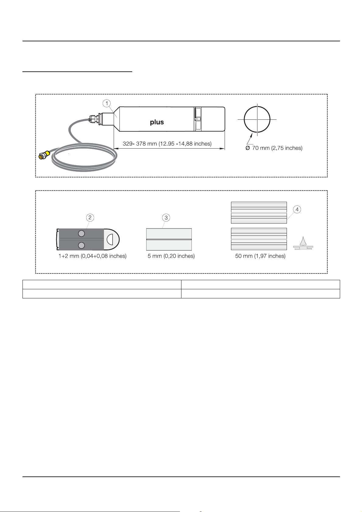
Figure 2 Sensor accessory components
1. UVAS sc sensor 3. Wiper profile (5 mm)
2. Wiper profile (1 and 2 mm) 4. Wiper profile (50 mm)
12
Page 13

Figure 3 Sensor bracket components
3
4
6
5
7
8
9
10
11
12
13
14
Installation
1. Mounting pipe 2.0 m 8. Cheese head bolt M8 x 40 (4)
2. 90° adapter 9. Sealing plug
3. Base 10. Plug
4. Clamp half (2) 11. O-ring EPDM
5. Clamp half with thread (2) 12. Flat seal
6. Cheese head bolt M5 x 20 (6) 13. Countersunk head bolt M6 x 8 (2)
7. Fastening lug 14. Cheese head bolt M3 x 10 (3)
13
Page 14

Installation
Figure 4 UVAS plus sc bypass accessories
1. Sample waste 2. Sample feed 3. Drain plug
14
Page 15

Figure 5 Installation overview, sensor bracket LZX414...
Installation
1. Base 8. Cheese head bolt M8 x 40 (4)
2. Anchors 9. Cheese head bolt with washer M3 x 10 (3)
3. Sealing plug 10. Flat seal
4. Plug 11. Adapter 90°
5. Mounting pipe 2.0 m 12. Countersunk head bolt M6 x 8 (2)
6. Retaining clamp (2) 13. O-ring EPDM
7. Fastening lug
3.3 Attaching the Sensorcable
3.4 Wiring safety information
WARNING
Electrical shock hazard. Always disconnect power to the instrument when making any
electrical connections.
15
Page 16

Installation
1
2
3
4
5
6
3.4.1 Sensor connection and wiring
CAUTION
Before power is applied, refer to the controller operation instructions.
The sensor cable is supplied with a keyed quick-connect fitting for easy
attachment to the controller. Retain the connector cap to seal the connector
opening in case the sensor must be removed. Optional extension cables may be
purchased to extend the sensor cable length.
Figure 6 Attaching the Sensor using the Quick-connect Fitting
Figure 7 Quick-connect Fitting pin assignment
Number Designation Wire Color
1 +12 VDC Brown
2 Circuit Common Black
3 Data (+) Blue
4 Data (–) White
5 Shield Shield (grey wire in existing quick-disconnect fitting)
6Groove
16
Page 17

Section 4 Operation
4.1 sc controller operation
The sensor can be operated with all sc controllers. Become familiar with the
functionality of the sc controller before using the sensor. Learn how to navigate
the menu and execute the corresponding functions.
4.2 Sensor setup
When the sensor is connected for the first time, the sensor serial number is
displayed as the sensor name. The sensor name can be changed as follows.
1. Open the MAIN MENU.
2. Press SENSOR SETUP and confirm.
3. Select the corresponding sensor and confirm.
4. Select CONFIGURE and confirm.
5. Press EDITED NAME and confirm.
6. Edit the names and confirm to return to the CONFIGURE menu.
Complete the system configuration in the same way by defining settings for the
following menu items:
• SET PARAMETER
• MEAS UNIT
• MEAS INTERVAL
• CORRELATION
• REFERENCE
• MEAS INTERVAL
• RESPONSE TIME
• CLEANING
• WIPER MODE
• BYPASS
• SET DEFAULTS
4.3 Sensor data logger
A data storage unit and an event memory unit are provided for each sensor. The
data storage unit stores measurement data at predefined time intervals, while the
event memory unit stores events such as configuration changes, alarms and
warning conditions. Both storage units can be output in CSV format (refer to
sc controller manual).
17
Page 18

Operation
4.4 Menu structure
4.4.1 SENSOR STATUS
SELECT SENSOR (if there is more than one sensor)
ERRORS
Possible error messages: MOIST, R < M, DEXT < 0.0, W. POS. UNKNOWN., W. BLOCKED, FLASH FAILURE, R
TOO HIGH
WARNIN GS
Possible warnings: EM TOO HIGH, CONC. TOO HIGH, CHECK KALIBR., REPLACE PROFILE, SERVICE
REQUIRED, REPLACE SEALS, REPL. MOTOR S.
Note: Refer to Section 6 Troubleshooting, page 31 for a list of all error and warning
messages as well as a description of all necessary corrective actions.
4.4.2 SENSOR setup
SELECT SENSOR (if there is more than one sensor)
CALIBRATION
FACTOR
OFFSET
ZERO CAL
1 SAMPLE CAL
VERIFY
OUTPUT MODE
CAL. CONFIG
CAL INTERVAL
SET CAL DEFLT
See 4.5.2 Zero point
calibration, page 23
See 4.5.3 1 point
calibration, page 23
See 4.6.1 Zero point
adjustment, page 24
ACTIVE
HOLD
TRANSFER
SELECTION
Counter for customer
cal.
0-30 d, default
setting: 0 d
Adjustable from 0.80-1.20 for matching the
comparison measurements
Adjustable from -250 to +250 mE for zero point
correction
Behaviour of the outputs during calibration or
zero point setting
18
Page 19

4.4.2 SENSOR setup
SELECT SENSOR (if there is more than one sensor)
CONFIGURATION
EDIT NAME 10-character
PARAMETER SAK254, SAC254, Ext254, Abs254, T/cm, BODuv, BSBuv, CSBuv, CODuv, DOCuv, TOCuv, ...
MEAS UNIT 1/m, mE, AU, %, mg/l, ppm
CORRELATION 2 value pairs: 1[1/m] and 1[mg/l] - 2[1/m] and 2[mg/l]
REFERENCE ON/OFF
MEAS INTERVAL
RESPONSE TIME
CLEANING 1/measurement, 1, 2, 3, 5, 6, 10, 12, 15, 20, 30 min, 1, 2, 3, 4, 6, 12 h, 10:00h
WIPER MODE
BYPASS yes/no
SET DEFAULTS ARE YOU SURE?
15, 20, 30 sec; 1, 2, 3, 4, 5, 6, 10, 12, 15, 20,
30 min
1-12 x MEAS
INTERVAL
SINGLE Normal setting
DOUBLE A-B-A
DOUBLE B-A-B
Indication of the
actual response time
in min.
Double wiping
frequency
Double wiping
frequency
MEAS INTERVAL: 5
min
RESPONSE TIME:
15 min
WIPER MODE: B-A-B
Operation
WIPER MODE: B
Inhibit wiper "extension"
Reset to the factory configuration.
19
Page 20

Operation
4.4.2 SENSOR setup
SELECT SENSOR (if there is more than one sensor)
MAINT.PROC
UVAS plus sc Instrument name
EDIT NAME
SERIAL NUMBER
FILTER DATA Measuring and reference wavelengths
RANGE
PROBE INFO
CAL. DATA
COUNTERS
PATHLENGTH Width of the measuring path
WIPER P/N Item number
MODEL NUMBER Item number
CODE VERSION Sensor software
DRIVER VERS
PRODUCTION DATE Production date
OFFSET
FACTOR
a Internal factor
b Internal factor
DATE
STD.: 3000 mE
DEXT 100%
DEXT 50%
DEXT 25%
GAIN Instrument factor
CAL. Date of the last factory calibration
r
m
ir
im
TOTAL TIME Counters
REPLACE PROFILE
CHECK CALIBR.
SERVICE
SEALS
SHAFTSEALS
MOTOR Counters
FLASH Counters
Counter 50000-0-neg.
number
Counter for test
interval
Counter 180 d-0-neg.
number
Counter 365 d-0-neg.
number
Counter 500000-0neg. number
Adjustable on the CALIBRATION menu
Date of the last change of OFFSET and/or
FACTOR
Internal calibration data
Internal calibration data
Negative if passed
20
Page 21

4.4.2 SENSOR setup
SELECT SENSOR (if there is more than one sensor)
MAINT.PROC
OUTPUT MODE
information
Operation
REPLACE PROFILE See 5.3 Changing wiper profile, page 29
WIPE (wiping process)
DRIVE OUT WIPER
(wiper profile extends, on bypass versions
WIPERTEST
SIGNALS
(Measurement 1/sec)
OUTPUT MODE
inhibited: see 5.2 Cleaning measuring path,
page 28
MOTOR CURRENT (motor current during the
wiping process)
Average value
Individual measured value
Single measured value for AQS
(FACTOR = 1, OFFSET = 0)
W.POS (wiper position)
DEXT (delta extinction EM-ER)
EM (extinction measuring channel)
ER (extinction reference channel)
M (measured level)
R (reference level)
IM (intensity measuring channel)
IR (intensity reference channel)
rd (dark value reference)
md (dark value measuring channel)
extd (dark value extinction )
MOIST
Behaviour of the instrument outputs when the
Maint.Proc. menu is opened
21
Page 22

Operation
4.5 Calibration
4.5.1 Verifying
The instrument has been carefully calibrated before delivery and the calibration
will not change for a long time.
It is recommended to regularly check the calibration (4.5.1 Verifying, page 22)
with a test glass. In case of large deviations, first a zero point calibration (4.5.2
Zero point calibration, page 23) must be performed to compensate for a zero point
offset, before the gradient is allowed to be changed with the 1 point calibration
(4.5.3 1 point calibration, page 23).
During the calibration only mE values are displayed. The setpoint adjustment is
also referred to the unit of measure mE. This setpoint is noted on the filter for the
verification, liquid standards must be measured with an external spectral
photometer and the measured values converted to the sensor layer thickness.
1. Open the MAIN MENU.
2. Press SENSOR SETUP and confirm.
3. Press SELECT SENSOR (if there is more than one sensor) and confirm.
4. Press CALIBRATION and confirm.
5. Remove sensor from the tank and rinse measuring path with water.
6. Press VERIFY and confirm. The wiper will come out.
7. Confirm INSERT FILTER PRESS ENTER TO CONTINUE...
8. Confirm WHEN STABLE PRESS ENTER X.X
9. Press CALIBRATION and confirm.
10. Edit in 1 SAMPLE-CAL. (+x.x) the setpoint adjustment according to the test
glass and confirm.
11. Confirm FACTOR: X.XX.
12. The corrected measured value is displayed. Confirm WHEN STABLE PRESS
ENTER X.X.
13. Press FINISH and confirm.
14. Confirm REMOVE FILTER PRESS ENTER.
Then the wiper moves out . Immerse sensor at the measuring location.
22
15. Press the back-button to leave the menu CALIBRATE.
16. Confirm RETURN PROBE TO PROCESS.
17. Confirm READY. Automatic wiping action and back to measurements.
Page 23

4.5.2 Zero point calibration
Operation
1. Open the MAIN MENU.
2. Press SENSOR SETUP and confirm.
3. Press SELECT SENSOR (if there is more than one sensor) and confirm.
4. Press CALIBRATION and confirm.
5. Select ZERO CAL and confirm.
6. Remove sensor from the tank and rinse measuring path with water. Align
measuring path horizontally and completely fill with distilled water. Confirm
FILL IN AQUA DEST PRESS ENTER TO CONTINUE.
7. Confirm WHEN STABLE PRESS ENTER DEXT: +/- X.X mE.
8. Press CALIBRATION and confirm.
9. Select OFFSET: X.X mE.
4.5.3 1 point calibration
10. Confirm WHEN STABLE PRESS ENTER +/- X.X.
11. Press FINISH and confirm.
12. Press the back-button to leave the menu CALIBRATE.
13. Immerse sensor at the measuring location and confirm RETURN PROBE TO
PROCESS.
14. Confirm READY. Automatic wiping action and back to measurements.
1. Open the MAIN MENU.
2. Press SENSOR SETUP and confirm.
3. Press SELECT SENSOR (if there is more than one sensor) and confirm.
4. Press CALIBRATION and confirm.
5. Select 1 SAMPLE CAL and confirm.
6. Remove sensor from the tank and rinse measuring path with water. Align
measuring path horizontally and completely fill with a reference sample.
Confirm FILL IN CAL STANDARD PRESS ENTER.
7. Confirm WHEN STABLE PRESS ENTER x. x.
8. Press CALIBRATION and confirm.
9. Edit in 1 SAMPLE-CAL. (+x.x) the setpoint adjustment according to the
reference sample and confirm.
23
Page 24

Operation
10. Confirm FACTOR: X.XX.
11. Confirm WHEN STABLE PRESS ENTER X.X.
12. Press FINISH and confirm.
13. Press the back-button to leave the menu CALIBRATE.
14. Immerse sensor at the measuring location and confirm RETURN PROBE TO
PROCESS.
15. Confirm READY. Automatic wiping action and back to measurements.
4.6 Adjusting measured values
If the comparative measurements in the laboratory do not provide adequate
agreement with the measured values from the probe, electronic measured value
adjustment (zero point and factor) can be performed as a provisional measure
until the next customer service visit.
The settings should also only be made when a zero point check after cleaning the
measuring window and the verification have been unsatisfactory.
4.6.1 Zero point adjustment
4.6.2 Setting factor
1. Open the MAIN MENU.
2. Press SENSOR SETUP and confirm.
3. Press SELECT SENSOR (if there is more than one sensor) and confirm.
4. Press CALIBRATION and confirm.
5. Press OFFSET and confirm.
6. Make a manual zero point offset by editing xx mE and confirm.
7. Press the back-button to leave the menu CALIBRATE.
8. Immerse sensor at the measuring location and confirm RETURN PROBE TO
PROCESS.
9. Confirm READY. Automatic wiping action and back to measurements.
1. Open the MAIN MENU.
24
2. Press SENSOR SETUP and confirm.
3. Press SELECT SENSOR (if there is more than one sensor) and confirm.
4. Press CALIBRATION and confirm.
5. Press FACTOR and confirm.
Page 25

6. Edit the Factor x.xx and confirm. The current measured value is multiplied by
this factor, from 0.80-1.20, before it appears as a calculated value on the
display.
7. Press the back-button to leave the menu CALIBRATE.
8. Immerse sensor at the measuring location and confirm RETURN PROBE TO
PROCESS.
9. Confirm READY. Automatic wiping action and back to measurements.
4.7 Conversion into other total parameters
SAC 254 is an independent total parameter for the dissolved organic content of
water and evaluates, like all other total parameters, only ever a specific fraction of
the water load. Despite their major similarities, total parameters can only be
converted from one to another within certain limits. However, if a correlation is
found between SAC 254 and another total parameter, the converted measured
values from UVAS probes can be displayed as mg/l TOCuv, CSBuv etc.
To determine the correlation, first a measurement of the SAC curve should be
made over a few days. Only a regular daily curve with pronounced low and high
load times such as with municipal waste water offers a good basis for satisfactory
conversion.
Operation
At the times of day found for low and high load
• A representative sample should be taken at the UVAS probe location,
• The related SAC value should be read and
• A laboratory measurement of the parameter to be correlated should be
made.
Example:
Sample 1 SAC 254: 105 1/m ; TOC: 150 mg/l:
Sample 2 SAC 254: 35 1/m ; TOC: 38 mg/l:
SENSOR SETUP
CONFIGURATION
SET PARAMETER
MEAS UNIT mg/l
CORRELATION
TOCuv
PAI R 1
1 [1/m] = 105
1 [mg/l] = 150
PAI R 2
2 [1/m] = 35
2 [mg/l] = 38
The correlation entered should be regularly checked by means of comparative
measurements in the laboratory.
25
Page 26

Operation
26
Page 27

Section 5 Maintenance
Pinch Hazard. Only qualified personnel should conduct the tasks described in this
section of the manual.
The cleanliness of the two measuring windows in the sensor measuring path is
crucial for correct measured results!
The measuring windows should be checked weekly for soiling and the wiper
profile checked for wear.
The seals must be replaced annually by the manufacturer's customer service! If the
seals are not changed regularly, water may enter the probe head and seriously damage
the instrument!
5.1 Maintenance schedule
Maintenance task
CAUTION
NOTICE
Visual inspection weekly
Check calibration
Inspection six months (counter)
Seal change annually (counter)
Wiper profile change as per counter
Consumables
Number Designation Average service life*
1 Wiper sets 1 year
1 Wiper motor 5 years
1 Seal set 1 year
1 Flash lamp 10 years
2 Measuring windows 5 years
1 Filter set 5 years
2 O-ring through-flow unit 1 year
* On operation as per factory settings and correct use
Comparative measurement weekly
(depending on the ambient conditions)
27
Page 28

Maintenance
5.2 Cleaning measuring path
Potential danger with contact with chemical/biological substances.
Working with chemical samples, standards and reagents can be dangerous.
Make yourself familiar with the necessary safety procedures and the correct handling of
the chemicals before use and read and follow all relevant safety data sheets.
Normal operation of this device may require the use of chemicals or samples that
are biologically unsafe.
• Observe all cautionary information printed on the original solution containers
and safety data sheets prior to their use.
• Dispose of all consumed solutions in accordance with the local and national
regulations and laws.
• Select the type of protective equipment suitable to the concentration and
quantity of the dangerous material being used.
If the wiper interval is set correctly and the wiper profile is changed on time,
additional cleaning of the measuring path is not necessary.
DANGER
1. Open the MAIN MENU.
2. Press SENSOR SETUP and confirm.
3. Press SELECT SENSOR (if there is more than one sensor) and confirm.
4. Press DIAG/TEST and confirm.
5. Press TEST/MAINT and confirm.
6. Press SIGNALS and confirm.
7. Remove sensor from the tank.
Depending on the degree and nature of the soiling, clean using window
cleaner, grease remover or 5 % hydrochloric acid (operating the wiper arm
using the Enter key can help the cleaning process.)
After leaving to soak for 5–10 minutes, you must carefully clean the
measuring path with distilled water. Objective: [ER] and [EM] < 500
Confirm ENTER=WIPE.
8. Press the back-button to leave the menu SIGNALS.
9. Press the back-button to leave the menu TEST/MAINT. Confirm RETURN
PROBE TO PROCESS.
28
10. Confirm READY. Automatic wiping action and back to measurements.
Page 29

5.3 Changing wiper profile
Obey the locally applicable accident prevention regulations. Wear protective gloves
where necessary during the change of the wiper rubber.
Note: Note for bypass version: First slide the sensor out of the though-flow cell until the
measuring path is visible and the wiper can be extended without resistance!
1. For this purpose on the menu SENSOR SETUP, CONFIGURATION, Set
Figure 8 Cahnging wiper profile
Maintenance
CAUTION
BYPASS to "no"!
2. Open the MAIN MENU.
3. Press SENSOR SETUP and confirm.
4. Press SELECT SENSOR (if there is more than one sensor) and confirm.
5. Press DIAG/TEST and confirm.
6. Press TEST/MAINT and confirm.
7. Press REPLACE PROFILE and confirm.
8. Lift retaining strap (1) and confirm REMOVE CAP.
Note: Only on instrument versions with 1 or 2 mm measuring path.
9. Confirm REPLACE PROFILE, PUT ON CAP. The wiper (2) moves out
automatically.
10. Press the back-button to leave the menu REPLACE PROFILE.
29
Page 30

Maintenance
LZX428
11. Immerse sensor at the measuring location and confirm RETURN PROBE TO
PROCESS.
12. Confirm READY. Automatic wiping action and back to measurements.
5.4 Seal change (bypass version)
5.4.1 UVAS plus sc
30
Page 31

Section 6 Troubleshooting
6.1 Error messages
Possible sensor error messages are displayed by the sc controller.
Table 4 Error messages
Error displayed Rectification
NONE
Check MOIST value on the SENSOR SETUP menu,
MOIST
R < M Call service
DEXT < 0.0 Check calibration, call service
W.POS. UNKNOWN Check measuring path, call service
W. BLOCKED Check measuring path, call service
FLASH FAILURE Call service
R TOO HIGH Call service
TEST/MAINT, MAINT.PROC., SIGNALS.
Remove sensor from the tank and call service
6.2 Warnings
Possible sensor warning messages are displayed by the sc controller.
Table 5 Warnings
Warning displayed Cause Rectification
NONE Correct measuring operation
EM TOO HIGH
CONC. TOO HIGH
CHECK KALIBR. Test interval elapsed Check calibration
REPLACE PROFILE Counter elapsed Change wiper profile
SERVICE REQUIRED Counter elapsed Call service
REPLACE SEALS Counter elapsed Call service
SHAFT SEALS REPL. Counter elapsed Call service
Turbidity, organic content or nitrate concentration too
high, measuring range exceeded as a result
Nitrate concentration too high, as a result measuring
range exceeded
Check measurement in the laboratory
Check measurement in the laboratory
31
Page 32

Troubleshooting
32
Page 33

Section 7 Replacement Parts
UVAS plus sc (1 mm) ..................................................................................................................... LXV418.00.10001
UVAS plus sc (2 mm) ..................................................................................................................... LXV418.00.20001
UVAS plus sc (5 mm) ..................................................................................................................... LXV418.00.50001
UVAS plus sc (50 mm) ................................................................................................................... LXV418.00.90001
User Manual .................................................................................................................................. DOC023.52.03230
Accessories
Cable extension set (5 m)............................................................................................................................... LZX437
Cable extension set (10 m)............................................................................................................................. LZX438
Cable extension set (15 m)............................................................................................................................. LZX439
Cable extension set (20 m)............................................................................................................................. LZX440
Cable extension set (30 m)............................................................................................................................. LZX462
Cable extension set (50 m)............................................................................................................................. LZX462
Cable extension set (100 m)........................................................................................................................... LZX512
Sensor bracket incl. 90° adapter .................................................................................................... LZX414.00.10000
Comprising:
Base .......................................................................................................................................................... ATS010
Fastening lug............................................................................................................................................. HPL061
Retaining clamp (2x).................................................................................................................................. LZX200
Mounting pipe 2 m.................................................................................................................................... BRO060
Hardware HS............................................................................................................................................. LZX416
Extension pipe 1.8 m ..................................................................................................................................... BRO062
Extension pipe 1.0 m ..................................................................................................................................... BRO061
Extension pipe 1.35 m................................................................................................................................... BRO068
Second fastening point (incl. retaining clamp)................................................................................................ LZX456
Probe adapter 90° ......................................................................................................................................... AHA034
Hardware, sensor fastening............................................................................................................................ LZX417
Base 90°......................................................................................................................................................... ATS011
Consumables
Wiper profile 1 mm (5 pcs.) ............................................................................................................................ LZX148
Wiper profile 2 mm (5 pcs.) ............................................................................................................................ LZX012
Wiper profile 5 mm (5 pcs.) .............................................................................................................................LZX117
Wiper profile 50 mm (10 pcs.) .........................................................................................................................LZX119
33
Page 34

34
Page 35

Section 8 Warranty and liability
The manufacturer warrants that the product supplied is free of material and
manufacturing defects and undertakes the obligation to repair or replace any
defective parts at zero cost.
The warranty period for instruments is 24 months. If a service contract is taken out
within 6 months of purchase, the warranty period is extended to 60 months.
With the exclusion of further claims, the supplier is liable for defects including the
lack of assured properties as follows: All those parts that, within the warranty
period calculated from the day of the transfer of risk, can be demonstrated to have
become unusable or that can only be used with significant limitations due to a
situation present prior to the transfer of risk, in particular due to incorrect design,
poor materials or inadequate finish will be improved or replaced, at the supplier's
discretion. The identification of such defects must be reported to the supplier in
writing without delay, but no later than 7 days after the identification of the fault. If
the customer fails to notify the supplier, the product is considered approved
despite the defect. Further liability for any direct or indirect damages is not
accepted.
If instrument-specific maintenance and servicing work defined by the supplier is to
be performed within the warranty period by the customer (maintenance) or by the
supplier (servicing) and these requirements are not carried out, claims for
damages due to the failure to comply with the requirements are rendered void.
Any further claims, in particular claims for consequential damages, cannot be
made.
Consumables and damage caused by improper handling, unsafe assembly or by
incorrect use are excluded from this provision.
Process instruments of the manufacturer are of proven reliability in many
applications and are therefore often used in automatic control loops to provide the
most economical operation possible for the related process.
To avoid or limit consequential damage, it is therefore recommended to design the
control loop such that a malfunction in an instrument results in an automatic
change over to the backup control system, which is the most secure operating
condition for the environment and for the process.
35
Page 36

36
Page 37

Section 9 Contact
HACH Company
World Headquarters
P.O. Box 389
Loveland, Colorado
80539-0389 U.S.A.
Tel (800) 227-HACH
(800) -227-4224
(U.S.A. only)
Fax (970) 669-2932
orders@hach.com
www.hach.com
HACH LANGE GMBH
Willstätterstraße 11
D-40549 Düsseldorf
Tel. +49 (0)2 11 52 88-320
Fax +49 (0)2 11 52 88-210
info@hach-lange.de
www.hach-lange.de
HACH LANGE GMBH
Rorschacherstrasse 30a
CH-9424 Rheineck
Tel. +41 (0)848 55 66 99
Fax +41 (0)71 886 91 66
info@hach-lange.ch
www.hach-lange.ch
Repair Service in the
United States:
HACH Company
Ames Service
100 Dayton Avenue
Ames, Iowa 50010
Tel (800) 227-4224
(U.S.A. only)
Fax (515) 232-3835
HACH LANGE LTD
Pacific Way
Salford
GB-Manchester, M50 1DL
Tel. +44 (0)161 872 14 87
Fax +44 (0)161 848 73 24
info@hach-lange.co.uk
www.hach-lange.co.uk
HACH LANGE FRANCE
S.A.S.
8, mail Barthélémy Thimonnier
Lognes
F-77437 Marne-La-Vallée
cedex 2
Tél. +33 (0) 820 20 14 14
Fax +33 (0)1 69 67 34 99
info@hach-lange.fr
www.hach-lange.fr
Repair Service in Canada:
Hach Sales & Service
Canada Ltd.
1313 Border Street, Unit 34
Winnipeg, Manitoba
R3H 0X4
Tel (800) 665-7635
(Canada only)
Tel (204) 632-5598
Fax (204) 694-5134
canada@hach.com
HACH LANGE LTD
Unit 1, Chestnut Road
Western Industrial Estate
IRL-Dublin 12
Tel. +353(0)1 460 2522
Fax +353(0)1 450 9337
info@hach-lange.ie
www.hach-lange.ie
HACH LANGE NV/SA
Motstraat 54
B-2800 Mechelen
Tel. +32 (0)15 42 35 00
Fax +32 (0)15 41 61 20
info@hach-lange.be
www.hach-lange.be
Repair Service in
Latin America, the
Caribbean, the Far East,
Indian Subcontinent, Africa,
Europe, or the Middle East:
Hach Company World
Headquarters,
P.O. Box 389
Loveland, Colorado,
80539-0389 U.S.A.
Tel +001 (970) 669-3050
Fax +001 (970) 669-2932
intl@hach.com
HACH LANGE GMBH
Hütteldorfer Str. 299/Top 6
A-1140 Wien
Tel. +43 (0)1 912 16 92
Fax +43 (0)1 912 16 92-99
info@hach-lange.at
www.hach-lange.at
DR. LANGE NEDERLAND
B.V.
Laan van Westroijen 2a
NL-4003 AZ Tiel
Tel. +31(0)344 63 11 30
Fax +31(0)344 63 11 50
info@hach-lange.nl
www.hach-lange.nl
HACH LANGE APS
Åkandevej 21
DK-2700 Brønshøj
Tel. +45 36 77 29 11
Fax +45 36 77 49 11
info@hach-lange.dk
www.hach-lange.dk
HACH LANGE LDA
Av. do Forte nº8
Fracção M
P-2790-072 Carnaxide
Tel. +351 214 253 420
Fax +351 214 253 429
info@hach-lange.pt
www.hach-lange.pt
HACH LANGE KFT.
Vöröskereszt utca. 8-10.
H-1222 Budapest XXII. ker.
Tel. +36 1 225 7783
Fax +36 1 225 7784
info@hach-lange.hu
www.hach-lange.hu
HACH LANGE AB
Vinthundsvägen 159A
SE-128 62 Sköndal
Tel. +46 (0)8 7 98 05 00
Fax +46 (0)8 7 98 05 30
info@hach-lange.se
www.hach-lange.se
HACH LANGE SP. ZO.O.
ul. Krakowska 119
PL-50-428 Wrocław
Tel. +48 801 022 442
Zamówienia: +48 717 177 707
Doradztwo: +48 717 177 777
Fax +48 717 177 778
info@hach-lange.pl
www.hach-lange.pl
HACH LANGE S.R.L.
Str. Căminului nr. 3,
et. 1, ap. 1, Sector 2
RO-021741 Bucureşti
Tel. +40 (0) 21 205 30 03
Fax +40 (0) 21 205 30 17
info@hach-lange.ro
www.hach-lange.ro
HACH LANGE S.R.L.
Via Rossini, 1/A
I-20020 Lainate (MI)
Tel. +39 02 93 575 400
Fax +39 02 93 575 401
info@hach-lange.it
www.hach-lange.it
HACH LANGE S.R.O.
Zastrčená 1278/8
CZ-141 00 Praha 4 - Chodov
Tel. +420 272 12 45 45
Fax +420 272 12 45 46
info@hach-lange.cz
www.hach-lange.cz
HACH LANGE
8, Kr. Sarafov str.
BG-1164 Sofia
Tel. +359 (0)2 963 44 54
Fax +359 (0)2 866 15 26
info@hach-lange.bg
www.hach-lange.bg
HACH LANGE S.L.U.
Edificio Seminario
C/Larrauri, 1C- 2ª Pl.
E-48160 Derio/Vizcaya
Tel. +34 94 657 33 88
Fax +34 94 657 33 97
info@hach-lange.es
www.hach-lange.es
HACH LANGE S.R.O.
Roľnícka 21
SK-831 07 Bratislava –
Vaj nory
Tel. +421 (0)2 4820 9091
Fax +421 (0)2 4820 9093
info@hach-lange.sk
www.hach-lange.sk
HACH LANGE SU
ANALİZ SİSTEMLERİ
LTD.ŞTİ.
Ilkbahar mah. Galip Erdem
Cad. 616 Sok. No:9
TR-Oran-Çankaya/ANKARA
Tel. +90312 490 83 00
Fax +90312 491 99 03
bilgi@hach-lange.com.tr
www.hach-lange.com.tr
37
Page 38

Contact
HACH LANGE D.O.O.
Fajfarjeva 15
SI-1230 Domžale
Tel. +386 (0)59 051 000
Fax +386 (0)59 051 010
info@hach-lange.si
www.hach-lange.si
HACH LANGE OOO
Finlyandsky prospekt, 4A
Business Zentrum “Petrovsky
fort”, R.803
RU-194044, Sankt-Petersburg
Tel. +7 (812) 458 56 00
Fax. +7 (812) 458 56 00
info.russia@hach-lange.com
www.hach-lange.com
ΗΑCH LANGE E.Π.Ε.
Αυλίδος 27
GR-115 27 Αθήνα
Τηλ . +30 210 7777038
Fax +30 210 7777976
info@hach-lange.gr
www.hach-lange.gr
HACH LANGE D.O.O.
Ivana Severa bb
HR-42 000 Varaždin
Tel. +385 (0) 42 305 086
Fax +385 (0) 42 305 087
info@hach-lange.hr
www.hach-lange.hr
HACH LANGE MAROC
SARLAU
Villa 14 – Rue 2 Casa
Plaisance
Quartier Racine Extension
MA-Casablanca 20000
Tél. +212 (0)522 97 95 75
Fax +212 (0)522 36 89 34
info-maroc@hach-lange.com
www.hach-lange.ma
38
Page 39

Appendix A ModBUS Register Information
Table 6 Sensor ModBUS Registers
Group Name Register # Data Type Length R/W Description
measurement 40001 Float 2 R diplayed measurement value
unit 40003 Unsigned Integer 1 R/W unit : mg/l = 0 : g/l = 1
parameter 40004 Unsigned Integer 1 R/W parameter
Measure interval 40005 Unsigned Integer 1 R/W measuring interval
correction 40006 Float 2 R/W correction
offset 40008 Float 2 R/W offset
integration 40010 Unsigned Integer 1 R/W integration, always 1
cleaning_interval 40011 Unsigned Integer 1 R/W cleaning interval
wiper mode 40012 Unsigned Integer 1 R/W wiper mode
wiper state 40013 Unsigned Integer 1 R/W wiper state
resp time 40014 Unsigned Integer 1 R/W response time
drv_struct_ver 40015 Unsigned Integer 1 R driver structure version
drv_firmw_ver 40016 Unsigned Integer 1 R driver firmware version
drv_cont_ver 40017 Unsigned Integer 1 R driver content version
location 40018 String 5 R/W location
path length 40023 Float 2 R path length
profile 40025 Integer 2 R profile counter
motor_cycles 40027 Integer 2 R motor cycles
flash_counter 40029 Integer 2 R flash counter
sealing_counter 40031 Integer 2 R sealing counter
service_counter 40033 Integer 2 R service counter
operating_hours 40035 Integer 2 R operating hours
shaft_sealing_counter 40037 Integer 2 R shaft sealing counter
profile reset val 40039 Integer 2 R/W profile reset val
seals reset val 40041 Integer 2 R/W seals reset val
service reset val 40043 Integer 2 R/W service reset val
shaft seal reset val 40045 Integer 2 R/W shaft seal reset val
des_measurement 40047 Float 2 R desired measurement value
meas_single_value 40049 Float 2 R measurement single value
dext 40051 Float 2 R delta extiction
EM 40053 Float 2 R m - extiction
ER 40055 Float 2 R r - extiction
M 40057 Float 2 R m
R 40059 Float 2 R r
intensity_mes 40061 Float 2 R m - intensity
intensity_ref 40063 Float 2 R r - intensity
humidity_main 40065 Float 2 R humidity - main
conc_blank 40067 Float 2 R concentration whithout correction
cal_date 40069 Time 2 R calibration time and date
user_cal_date 40071 Time 2 R user calibration time and date
std_s3 40073 Float 2 R standard S3
cal_L1 40075 Float 2 R cal. point 1
39
Page 40

ModBUS Register Information
Table 6 Sensor ModBUS Registers
cal_L2 40077 Float 2 R cal. point 2
cal_L3 40079 Float 2 R cal. point 3
cal_mes 40081 Float 2 R m - calibration
cal_ref 40083 Float 2 R r - calibration
cal_intensity_mes 40085 Float 2 R intensity m - calibration
cal_intensity_ref 40087 Float 2 R intensity r - calibration
cal_ext 40089 Float 2 R extinction - calibration
process 40091 Unsigned Integer 1 R/W process register
menu 40092 Unsigned Integer 1 R menu state
gain_ref 40093 Integer 1 R
gain_mes 40094 Integer 1 R
wiper_lim_a 40095 Integer 1 R wiper limit a
wiper_lim_b 40096 Integer 1 R wiper limit b
wiper_lim_out 40097 Integer 1 R wiper limit out
prg_vers 40098 String 4 R program version
ser_no 40102 Integer 2 R serial number
cal_out_cfg 40104 Integer 1 R cal. Output mode
user_cal_int 40105 Integer 1 R/W user calibration interval
wiper_current 40106 Integer 1 R wiper motor current in mA
resp_time_min 40107 Integer 1 R response time in min
flash_per_fil 40108 Integer 2 R flash per filter
cm1 40110 Float 2 R/W meas. Cap 1
cm2 40112 Float 2 R/W meas cap 2
cr1 40114 Float 2 R/W ref cap1
cr2 40116 Float 2 R/W ref cap2
lambda_m 40118 Float 2 R/W lambda meas
lambda_r 40120 Float 2 R/W lambda ref
transm_m 40122 Float 2 R/W transmission meas
transm_r 40124 Float 2 R/W ransmission ref
cal_menu 40126 Unsigned Integer 1 R/W cal menu
wiper_menu 40127 Unsigned Integer 1 R/W wiper menu
maint_menu 40128 Unsigned Integer 1 R/W maint_menu
service_menu 40129 Unsigned Integer 1 R/W service menu
flash_repl 40130 Unsigned Integer 1 R/W flash replaced question
edit_menu 40131 Unsigned Integer 1 R/W edit menu
def_menu 40132 Unsigned Integer 1 R/W default menu
filter_data_menu 40133 Unsigned Integer 1 R/W filter data menu
prod_date 40134 Time 2 R production date
sensor_type 40136 String 8 R/W sensor type
filter_set 40144 String 3 R/W filter set
user_cal_counter 40147 Integer 1 R user cal. Counter
pos_out_en 40148 Unsigned Integer 1 R/W pos. Out enable
low byte = gain ref-channel, high byte =
second cap. on/off
low byte = gain mes-channel, high byte =
second cap. on/off
40
 Loading...