

Page 1

DOC022.98.93082
TitraLab® KF1000 series
workstations
12/2014, Edition 1
Basic User Manual
Manuale dell'utente di base
Manuel d'utilisation de base
Manual básico del usuario
Manual básico do utilizador
Základní uživatelská příručka
Grundlæggende brugervejledning
Basisgebruikershandleiding
Podstawowa instrukcja obsługi
Grundläggande bruksanvisning
Основно ръководство за потребителя
Alapvető felhasználói kézikönyv
Manual de bază al utilizatorului
Temel Kullanıcı Kılavuzu
Základný návod na použitie
Osnovni uporabniški priročnik
Osnovni korisnički priručnik
Βασικό εγχειρίδιο χρήσης
Basishandbuch
Peruskäyttöohje
Page 2

English..............................................................................................................................3
Deutsch.......................................................................................................................... 23
Italiano............................................................................................................................ 45
Français......................................................................................................................... 67
Español.......................................................................................................................... 89
Português.................................................................................................................... 111
Čeština......................................................................................................................... 133
Dansk............................................................................................................................154
Nederlands................................................................................................................. 175
Polski............................................................................................................................ 197
Svenska....................................................................................................................... 219
Suomi............................................................................................................................240
български................................................................................................................... 260
Magyar......................................................................................................................... 282
Română....................................................................................................................... 303
Türkçe...........................................................................................................................325
Slovenský jazyk......................................................................................................... 345
Slovenski..................................................................................................................... 367
Hrvatski........................................................................................................................ 388
Ελληνικά...................................................................................................................... 408
2
Page 3

Table of contents
Specifications on page 3 Startup on page 15
General information on page 3 Standard operations on page 16
Installation on page 7 Maintenance on page 19
Keypad on page 14 Troubleshooting on page 22
Additional information
Additional information is available on the manufacturer's website.
Specifications
Specifications are subject to change without notice.
Specification Details
Dimensions (W x D x H) 22 x 40 x 36 cm (8.7 x 15.7 x 14.2 in.)
Weight 4 kg (8.8 lb)
Power requirements 100–240 VAC, 50/60 Hz
Altitude 2,000 m (6,562 ft) maximum
Operating temperature 15 to 35 °C (59 to 95 °F)
Relative humidity 20 to 80%, non-condensing
Storage temperature –5 to 40 °C (23 to 104 °F)
Installation category II
Pollution degree 2
Certifications Safety IEC/EN 61010-1; EMC IEC/EN 61326-1
Warranty 1 year (EU: 2 years)
General information
In no event will the manufacturer be liable for direct, indirect, special, incidental or consequential
damages resulting from any defect or omission in this manual. The manufacturer reserves the right to
make changes in this manual and the products it describes at any time, without notice or obligation.
Revised editions are found on the manufacturer’s website.
Safety information
N O T IC E
The manufacturer is not responsible for any damages due to misapplication or misuse of this product including,
without limitation, direct, incidental and consequential damages, and disclaims such damages to the full extent
permitted under applicable law. The user is solely responsible to identify critical application risks and install
appropriate mechanisms to protect processes during a possible equipment malfunction.
Please read this entire manual before unpacking, setting up or operating this equipment. Pay
attention to all danger and caution statements. Failure to do so could result in serious injury to the
operator or damage to the equipment.
Make sure that the protection provided by this equipment is not impaired. Do not use or install this
equipment in any manner other than that specified in this manual.
English
3
Page 4

Use of hazard information
D A N GE R
Indicates a potentially or imminently hazardous situation which, if not avoided, will result in death or serious injury.
Indicates a potentially or imminently hazardous situation which, if not avoided, could result in death or serious
injury.
Indicates a potentially hazardous situation that may result in minor or moderate injury.
Indicates a situation which, if not avoided, may cause damage to the instrument. Information that requires special
emphasis.
W A R NI N G
C A U TI O N
N O T IC E
Precautionary labels
Read all labels and tags attached to the instrument. Personal injury or damage to the instrument
could occur if not observed. A symbol on the instrument is referenced in the manual with a
precautionary statement.
This symbol, if noted on the instrument, references the instruction manual for operation and/or safety
information.
This symbol indicates that a risk of electrical shock and/or electrocution exists.
This symbol indicates the presence of devices sensitive to Electro-static Discharge (ESD) and
indicates that care must be taken to prevent damage with the equipment.
Electrical equipment marked with this symbol may not be disposed of in European public disposal
systems after 12 August of 2005. In conformity with European local and national regulations (EU
Directive 2002/96/EC), European electrical equipment users must now return old or end-of-life
equipment to the Producer for disposal at no charge to the user.
Certification
Canadian Radio Interference-Causing Equipment Regulation, IECS-003, Class A:
Supporting test records reside with the manufacturer.
This Class A digital apparatus meets all requirements of the Canadian Interference-Causing
Equipment Regulations.
Cet appareil numérique de classe A répond à toutes les exigences de la réglementation canadienne
sur les équipements provoquant des interférences.
FCC Part 15, Class "A" Limits
Supporting test records reside with the manufacturer. The device complies with Part 15 of the FCC
Rules. Operation is subject to the following conditions:
1. The equipment may not cause harmful interference.
2. The equipment must accept any interference received, including interference that may cause
undesired operation.
Changes or modifications to this equipment not expressly approved by the party responsible for
compliance could void the user's authority to operate the equipment. This equipment has been tested
4
English
Page 5

and found to comply with the limits for a Class A digital device, pursuant to Part 15 of the FCC rules.
These limits are designed to provide reasonable protection against harmful interference when the
equipment is operated in a commercial environment. This equipment generates, uses and can
radiate radio frequency energy and, if not installed and used in accordance with the instruction
manual, may cause harmful interference to radio communications. Operation of this equipment in a
residential area is likely to cause harmful interference, in which case the user will be required to
correct the interference at their expense. The following techniques can be used to reduce
interference problems:
1. Disconnect the equipment from its power source to verify that it is or is not the source of the
interference.
2. If the equipment is connected to the same outlet as the device experiencing interference, connect
the equipment to a different outlet.
3. Move the equipment away from the device receiving the interference.
4. Reposition the receiving antenna for the device receiving the interference.
5. Try combinations of the above.
Product overview
The instrument operates with digital and analog sensors. Measurement applications are installed on
the instrument to automate the measurement process. Instructions show on the display when user
intervention is required. Refer to Figure 1 for product features.
Figure 1 Product overview
1 Keypad 6 Beaker 11 Sensor holder
2 Display 7 Syringe protection cover 12 Pump 2 input/output (waste)
3 Sensor storage tubes 8 Syringe input/output 13 Pump 1 input/output (solvent)
4 USB port 9 Tube clips 14 Pump access cover
5 Sample stopper 10 Syringe
Table 1 Instrument configuration
Model Syringes Pumps
KF1121 1 2
English 5
Page 6

Instrument connections
Figure 2 shows the connections on the rear panel of the instrument. Use the USB port on the side of
the instrument for the USB applications key supplied with the instrument. Use the USB port on the
rear of the instrument to connect to a printer, mouse, keyboard or a USB hub.
Figure 2 Instrument connections
1 24 V external power supply port 4 Not used 7 USB port
2 Sensor 1 port 5 Not used 8 Ethernet port
3 Sensor 2 port 6 Serial port
Product components
Make sure that all components have been received. Refer to the packing list in the box. If any items
are missing or damaged, contact the manufacturer or a sales representative immediately.
Figure 3 Contents of the instrument box
1 Instrument 3 Sensor storage tubes (3x) 5 Power cord
2 Sample stopper 4 Power supply
6 English
Page 7

Figure 4 Contents of the application box
1 KF standard beaker 6 Syringe holding ring
2 KF white Teflon® conical adapter 7 Syringe
3 Magnetic stir bars (10x) 8 Glass bottle
4 USB applications key 9 Bottle caps (3 x GL45)
5 Sensor 10 Desiccant cartridges (3x)
1
Installation
C A U TI O N
Multiple hazards. Only qualified personnel must conduct the tasks described in this section of the
document.
Installation guidelines
• This instrument is for indoor use only.
• The power supply connector on the rear panel must be easily accessible so the power can be
disconnected quickly in case of emergency.
• Keep the instrument away from temperature extremes, including heaters, direct sunlight and other
heat sources.
• Put the instrument on a stable and level surface in a well ventilated place.
• Make sure that there is at least 15 cm (6 in.) of space on all sides of the instrument to prevent
electrical parts from overheating.
• Do not operate or keep the instrument in dusty, damp or wet locations.
• Always keep the surface of the instrument and all accessories dry and clean.
1
2 filled with a molecular sieve, and 1 empty
English 7
Page 8

Connect to AC power
D A N GE R
Electrocution hazard. If this equipment is used outdoors or in potentially wet locations, a Ground Fault
Circuit Interrupt (GFCI/GFI) device must be used for connecting the equipment to its main power
source.
Electrical shock and fire hazards. Make sure that the supplied cord and non‐locking plug meet the
applicable country code requirements.
Fire hazard. Use only the power supply that is specified for this instrument.
1. Connect the power cord to the power supply.
2. Connect the power supply to the instrument. Refer to Figure 2 on page 6.
3. Connect the power cord to an electrical outlet.
C A U TI O N
W A R NI N G
Install the syringe
Before syringe installation, set the instrument power to on. Push the power button on the front of the
instrument. Make sure that the startup sequence shows on the display. The syringe holder lowers to
its operating position.
Note: Ignore any warning messages related to missing applications that show on the display.
The sensor holder has two positions: one over the magnetic stirrer and the second at 180° to the
right. Move the sensor holder away from the instrument to the second position.
Refer to the illustrated steps that follow.
8
English
Page 9

Install the sensor storage tubes
Put the three sensor storage tubes into the holder that is on the side of the instrument. Refer to
Figure 1 on page 5.
English
9
Page 10

Install the sensor holder accessories
Add the stir bar to the beaker, and then attach the beaker to the sensor holder. Install the desiccant
cartridge and the sample stopper. Refer to the illustrated steps that follow.
Prepare the tubes
Remove any bends in the end of the tubes. Refer to the illustrated steps that follow.
Connect the tubes
Arrow symbols identify the inlet and outlet ports for the syringe and the pump connections. The “up”
arrow is the outlet port. The “down” arrow is the inlet port. Turn the tube connectors on the inlet and
outlet ports of the syringe and pump until they click.
The suction tube that drains into the waste bottle must be installed on the bottom of the beaker for
good drainage.
N O T IC E
The diffusion tip and tube holder on the outlet tube, are pre-installed at the optimal positions. Do not change the
position of the diffusion tip or the tube holder.
Refer to the illustrated steps that follow.
10
English
Page 11

Install the sensor
Connect the sensor
Use a conical adapter to hold the sensor tightly in the sensor holder. Make sure the conical adapter
is installed correctly. This makes sure of a secure water-tight fitting in the sensor holder and the tip of
the sensor will be in the correct position in the beaker.
Connect the sensor to an available sensor port on the rear of the instrument. After the sensor is
connected, make sure that the sensor icon shows in the banner at the top of the display. Refer to the
illustrated steps that follow.
English
11
Page 12

Install the titrant and the reagent
Chemical exposure hazard. Obey laboratory safety procedures and wear all of the personal protective
equipment appropriate to the chemicals that are handled. Refer to the current safety data sheets
(MSDS/SDS) for safety protocols.
12 English
C A U TI O N
Page 13

Loosen the tube connector on the bottle cap.
Put a filled desiccant cartridge into the adapter on the titrant and solvent bottle caps. Put an empty
desiccant cartridge into the adapter on the waste bottle cap.
Note: The molecular sieve in the filled cartridges must be regenerated regularly depending on the humidity of the
laboratory. Refer to Regenerate the molecular sieve on page 19.
Push the inlet tube through the connector. Make sure that the end of the tube is at the bottom of the
bottle. Tighten the connector on the bottle cap.
Pump 1 is used to fill the measurement cell with solvent. Pump 2 is used to empty the measurement
cell. Refer to the illustrated steps that follow.
Tidy the work area
Attach the tubes to the instrument with the clips on the electrovalve and the sensor holder. Refer to
the illustrated steps that follow.
English
13
Page 14
User interface and navigation
Keypad
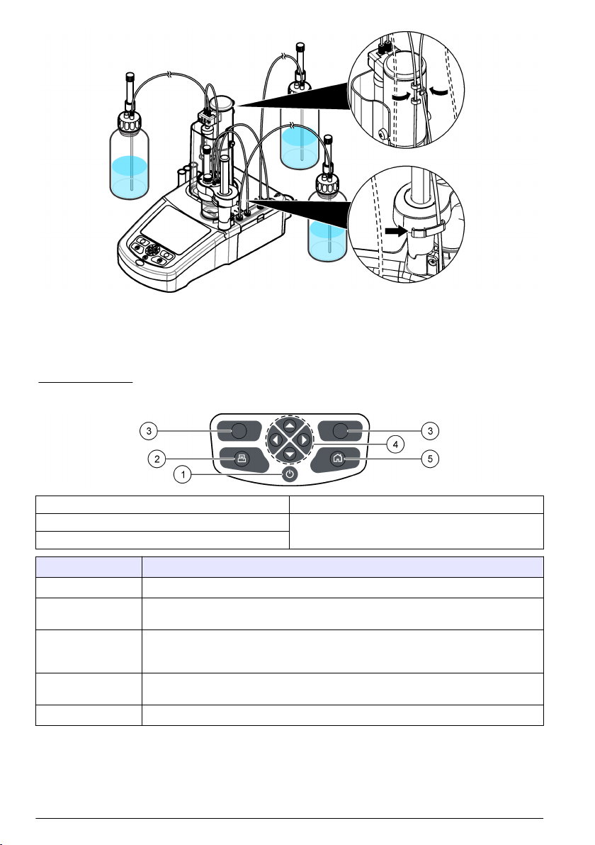
Figure 5 shows the keypad and gives the key functions.
Figure 5 Keypad
1 Power 4 Navigation keys
2 Printer 5 Home
3 Selection keys
Key Description
Power Sets the instrument power to on or off. Push the key for 2 seconds to set the power to off.
Printer Sends data to an attached printer. The printer key only operates if a printer is connected
Selection keys
(contextual)
Navigation keys Scrolls through menus and data, enter numbers and letters, enter checkbox settings and
Home Goes to the main menu.
to the instrument.
Shows the measurement options, selection and confirmation options. Use this key to exit
the current menu display or open sub-menus. Available options show on the display
above each key.
set options for the syringe and the pump.
14 English
Page 15

Startup
C A U TI O N
Chemical exposure hazard. Obey laboratory safety procedures and wear all of the personal protective
equipment appropriate to the chemicals that are handled. Refer to the current safety data sheets
(MSDS/SDS) for safety protocols.
C A U TI O N
Personal injury hazard. Never use the instrument without the syringe cover installed.
Configure the instrument
1. From the main menu, select Settings.
2. Select an option, then push Select.
Option Description
Applications Exports, changes (refer to Change the application settings on page 15), removes and
makes copies of application data. Make sure that the duplication function does not make
more than five applications.
Operators Adds, changes and removes operators.
Date + Time Sets the instrument date and time.
Brightness Sets the brightness of the display.
Sounds Sets the sound options.
Language Sets the language.
Network Give a name to the instrument. This name is used to connect the instrument to a PC.
Restart the instrument if the name is changed.
Legacy settings Specify the sensor data when the legacy adapter is used.
Info Shows information about the instrument and the attached hardware.
Restore Defaults Sets the instrument to the default configuration.
Options Sets the application parameters view to expert mode (refer to Change the application
settings on page 15). When the instrument is set to off, sets the syringe to empty into
the titrant bottle. Changes the temperature display unit. Prints the measurement curve if a
printer is connected.
3. Push Back.
Change the application settings
N O T IC E
The applications installed on the instrument have been pre-defined to optimize the measurement process.
Changing these default application parameters will have an effect on the measurement process and
measurement results. Only qualified personnel should change these parameters or use the instrument in expert
mode.
1. From the main menu, select Settings.
2. Select Applications followed by Edit.
3. Choose an application to change from the installed list and then push Edit.
English
15
Page 16

4. Push the arrow keys to scroll through the application parameters. The Edit key is only available
when a parameter can be changed.
Note: More parameters can be changed with the instrument in expert mode.
5. Push Edit to change the parameter. Enter the new details or select from a list.
Install the applications
Use the supplied USB key to install the applications. The instrument can install a maximum of five
applications. The installed applications are shown on the top line of the display. If any errors occur
during installation, refer to Troubleshooting on page 22.
1. Push Home to go to the main menu.
2. Connect the USB key to the USB port on the side of the instrument. The applications on the USB
key show on the display.
3. Push the arrow keys to highlight and select an application to install. Push the left or right arrow
key to select it. Do this step again to select additional applications to install.
4. Push Import to install the selected applications.
5. Push OK to complete the installation. The installed applications show on the main menu.
Note: To install more applications, push Home to go to the main menu, then remove the USB key and
reconnect it.
Prepare the instrument for measurement
1. From the main menu, select Purge, then push Start. All attached devices are listed.
2. Select All elements to purge all the attached devices, or select one device to purge. Push
Select. Air is removed from the device and filled with liquid from the bottle.
3. Push OK when the operation has completed.
4. Make sure that there are no air bubbles in the device. Do step 2 again if there are any air
bubbles.
5. Select the next device to purge if individual devices are being selected.
6. Push Exit when all the tubes are filled with reagent and the device has no air bubbles.
Note: If a few small air bubbles can be seen on the inner wall and/or piston of the syringe, they can be left
without effecting system performance.
Standard operations
C A U TI O N
Multiple hazards. Only qualified personnel must conduct the tasks described in this section of the
document.
C A U TI O N
Chemical exposure hazard. Obey laboratory safety procedures and wear all of the personal protective
equipment appropriate to the chemicals that are handled. Refer to the current safety data sheets
(MSDS/SDS) for safety protocols.
C A U TI O N
Personal injury hazard. Never use the instrument without the syringe protection cover in place.
Chemical exposure hazard. Never remove the stir bar from the beaker before the end of a titration.
16 English
C A U TI O N
Page 17

Get a sample measurement
Use this option to get sample measurements with one of the installed applications.
1. Make sure that the glass beaker, the sensor holder and all related parts are clean and dry. Put a
magnetic stir bar into the beaker.
2. Attach the beaker to the sensor holder. Make sure that the beaker fits tightly into the sensor
holder.
3. Read the related "Application Note" from the USB applications key for more instructions.
4. Fill the beaker with the applicable amount of solvent. Refer to Cell management on page 18.
Make sure that there is no liquid spill. Make sure that the initial level is enough so that the sensor
is correctly installed in the sample. Do not put too much solvent in the beaker.
5. From the main menu, select the measurement application, then push Start. Application
information shows on the display.
6. If necessary, select an icon for more information or to change some data.
7. Make sure that the icon at the bottom of the display is highlighted. Do the instructions that
show on the display adjacent to this icon. Make sure that the tubes and sensor are correctly
aligned.
8. Push Start to start the cell conditioning. Measurement data shows on the display.
9. If the default stirring speed needs to be adjusted, push the up and down arrow keys to increase or
decrease the speed.
Note: Changing the default stirring speed can effect the measurement result.
10. If the options are available during the measurement procedure, push Skip to ignore the current
step or push Stop to abort the measurement.
11. Weigh the sample in its container and write down the result.
12. When the cell conditioning is complete add the sample. Remove the sample stopper and put the
correct amount of sample into the beaker with an applicable utensil. Make sure that all of the
sample is put into the center of the beaker and that none of it spills onto the walls of the beaker.
13. Put the sample stopper back into the sensor holder. Make sure that the sample stopper fits tightly
into the sensor holder.
14. Weigh the empty sample container and subtract this value from the weight of the sample in its
container (refer to step 11). The result is the exact weight of the sample analyzed. Write down
this value.
15. Push Start to start the moisture content analysis. Measurement data shows on the display.
Note: The moisture content analysis will start automatically after the addition of sample if the Injection
Autodetect parameter is set to Yes.
16. If the default stirring speed needs to be adjusted, push the up and down arrow keys to increase or
decrease the speed.
Note: Changing the default stirring speed can effect the measurement result.
17. If the options are available during the measurement procedure, push Skip to ignore the current
step or push Stop to abort the measurement.
18. When the measurement is complete, enter the exact weight of the sample analyzed (refer to step
14). Push the arrow keys to see the different measurement views.
19. Push Next for the options that follow:
Option Description
Replicate sample Use this option to start the same titration on the same sample. This is used to study the
repeatability by successively analyzing several parts of the same sample. At the end of
each measurement, a window shows the average value, the standard deviation and the
relative standard deviation.
English 17
Page 18

Option Description
New sample Use this option to start the same titration on a new sample. No standard deviation or
Cell management Use this option to fill or empty the measurement cell with the pumps. Refer to Cell
relative standard deviation measurements will be done.
management on page 18.
20. Push Exit to go back to the main menu.
Cell management
Use this option to fill or empty the measurement cell with the pumps.
1. From the main menu, select Cell management.
2. Push the left and right arrow keys to make a selection.
Option Description
Fill cell (pump 1) Use this option to fill the measurement cell with reagent from pump 1. Push the up arrow
Empty cell
(pump 2)
to stop the procedure.
C A U TI O N
Chemical exposure hazard. Before selecting this option, examine the level of liquid in
the waste bottle. Make sure that there is enough space in the bottle for all of the liquid
from the measurement cell.
Use this option to empty the measurement cell with pump 2. Push the up arrow to stop
the procedure.
3. Push Exit to go back to the main menu.
Manage the data log
To select data to view, delete or export, specify data filters
1. From the main menu, select Data log.
2. Select an option, then push Select.
Option Description
View data log Views measurement data. Select individual lines of data to view more content.
Export data log Exports measurement data from the system to an external device. Preview data selection
Delete data log Removes measurement data from the system. Previews data selection before it is
before it is exported. Make sure that an external device is connected to the instrument
(e.g., a USB key, external hard drive, etc.).
removed.
3. Specify the data extraction parameters. Push the left and right arrow keys to make a selection.
Push the up and down arrow keys to select an option.
Option Description
Result type Sets the type of result available.
Application Sets the available applications.
Date Sets the date range.
Operator Sets the available operators.
18 English
Page 19

Calibration
Calibrate the titrant
1. From the main menu, select Calibration. Related information shows on the display.
2. If necessary, select an icon for more information or to change some data.
3. Do the instructions that show on the display, then push Start to start the calibration. Calibration
data shows on the display.
4. If the default stirring speed needs to be adjusted, push the up and down arrow keys to increase or
decrease the speed.
5. When the calibration is complete, push the arrow keys to see the different measurement views.
6. Push Continue to continue with the calibration.
7. When the calibration is complete, push Yes to accept the calibration or No to reject.
8. Push Exit to go back to the main menu.
Purge
Use this procedure to remove air bubbles from the system. Refer to Prepare the instrument for
measurement on page 16 for instructions.
Maintenance
C A U TI O N
Multiple hazards. Only qualified personnel must conduct the tasks described in this section of the
document.
N O T IC E
Do not disassemble the instrument for maintenance. If the internal components must be cleaned or repaired,
contact the manufacturer.
Clean the instrument
N O T IC E
Never use flammable or corrosive solvents to clean any part of the instrument. Use of these solvents can degrade
the environmental protection of the instrument and may void the warranty.
Clean the exterior surface with a moist cloth or with a mixture of water and mild detergent. Dry with a
soft cloth.
Clean the sensor
Refer to the documentation delivered with the sensor.
Regenerate the molecular sieve
It is recommended to regenerate the molecular sieve weekly, but this will vary depending on the
humidity of the laboratory. A humidity indicator, such as color changing silica gel crystal, can be used
to show when regeneration is necessary.
To regenerate the molecular sieve, dry it in an oven at a temperature of 300 °C (572 °F) for at least
4 hours. When cool, it can be kept in a glass bottle with an airtight seal.
English
19
Page 20

Maintenance menu
Select Maintenance from the main menu.
Syringe activation
Do a check of the syringe. Make sure the syringe fills and empties correctly.
1. From the maintenance menu, push Syringe activation.
Option Description
Fill Fills the syringe with titrant solution. The process stops automatically when the syringe is
Empty to bottle Discards the contents of the syringe into the titrant bottle.
Empty to beaker Discards the contents of the syringe into the beaker. Make sure that the tube from the
Stop Stops the operation.
Syringe replacement
To replace the syringe, select Syringe replacement from the maintenance menu. Obey the
instructions on the display. Refer to Install the syringe on page 8.
Pump activation
This option only applies to instruments with pumps installed. Do a check of the pump. Make sure the
pump fills and empties correctly.
1. From the maintenance menu, push Pump activation.
Option Description
Start Starts the pump. The reagent is pumped through the tubes into the beaker. Make sure that the tube
from the outlet port of the pump is in the beaker.
Stop Stops the operation.
2. Push Toggle to change to the second pump.
full.
outlet port of the syringe is inside the beaker.
Pump cassette replacement
D A N GE R
Electrocution hazard. Remove power from the instrument before this procedure is started.
This option only applies to instruments with pumps installed.
To replace the pump cassette, refer to the illustrated steps that follow and obey the instructions on
the display.
20
English
Page 21

English 21
Page 22

Other maintenance options
1. Select an option, then push Select.
Option Description
Stirring activation Do a check of the magnetic stirrer. Push the up and down arrow keys to increase or
Live measure This option is not available for all sensors. The option shows continuous
Maintenance
summary
Maintenance
schedule
Reagent
replacement
decrease the stirring speed.
measurement data with connected sensors to quickly check measurements. The
installed applications and the automatic additions to the sample are set to off.
Continuous measurements are not temperature compensated, so measurement
differences may occur in the same sample between continuous measurements and
measurements that use installed applications with temperature compensation.
See the number of days remaining for maintenance tasks. After doing a task, push
Reset to set the number of days remaining to the default value.
See the list of maintenance tasks. Push Edit to change the default value.
Use this option to replace the reagents. Obey the instructions on the display.
Troubleshooting
Refer to the following table for common problem messages or symptoms and possible causes.
Error/Warning Description
Stop requested The operator has pushed the stop button
Measurement out of range The measurement is out of range
Temperature out of range The temperature measurement is out of range
Temperature unknown The temperature measurement cannot be determined
Temperature variation too high The variation in temperature is too high
Out of range The computed result is outside accepted limits
Equation calc. error An equation variable is unknown
Titrant calibration has expired The Calibration date has expired
Maximum number of applications is reached The maximum number of applications per line has been
Requires at least one titrant that cannot be
installed
Calibration solution already used The calibration solution has already been used
No titrant information System failure. Contact technical support
No measure received System failure. Contact technical support
Burette fails to deliver The syringe cannot be emptied
Burette fails to fill The syringe cannot be filled
Burette failed to read delivered volume System failure. Contact technical support
Excess of titrant Too much titrant during cell conditioning
Excess of water Too much water during cell conditioning
reached
The application is not compatible with applications already
installed as it uses a different titration
22 English
Page 23

Inhaltsverzeichnis
Spezifikationen auf Seite 23 Inbetriebnahme auf Seite 36
Allgemeine Informationen auf Seite 23 Standardfunktionen auf Seite 38
Installation auf Seite 28 Wartung auf Seite 41
Tastenfeld auf Seite 35 Fehlerbehebung auf Seite 44
Zusätzliche Informationen
Zusätzliche Informationen finden Sie auf der Website des Herstellers.
Spezifikationen
Die Spezifikationen können ohne Vorankündigung Änderungen unterliegen.
Spezifikation Details
Abmessungen (B x T x H) 22 x 40 x 36 cm (8,7 x 15,7 x 14,2 in)
Gewicht 4 kg / 8,8 lb
Leistungsbedarf 100-240 VAC 50/60 Hz
Einsatzhöhe Maximal 2.000 m (6,562 Fuß)
Betriebstemperatur 15 bis 35 °C (59 bis 95 °F)
Relative Feuchtigkeit 20 bis 80% (nicht kondensierend)
Lagerungstemperatur -5 bis 40 °C (23 bis 104 °F)
Einbaukategorie II
Verschmutzungsgrad 2
Zertifikationen Sicherheit IEC/EN 61010-1; EMC IEC/EN 61326-1
Garantie 1 Jahr (EU: 2 Jahre)
Allgemeine Informationen
Der Hersteller ist nicht verantwortlich für direkte, indirekte, versehentliche oder Folgeschäden, die
aus Fehlern oder Unterlassungen in diesem Handbuch entstanden. Der Hersteller behält sich
jederzeit und ohne vorherige Ankündigung oder Verpflichtung das Recht auf Verbesserungen an
diesem Handbuch und den hierin beschriebenen Produkten vor. Überarbeitete Ausgaben der
Bedienungsanleitung sind auf der Hersteller-Webseite erhältlich.
Sicherheitshinweise
H I N WE IS
Der Hersteller ist nicht für Schäden verantwortlich, die durch Fehlanwendung oder Missbrauch dieses Produkts
entstehen, einschließlich, aber ohne Beschränkung auf direkte, zufällige oder Folgeschäden, und lehnt jegliche
Haftung im gesetzlich zulässigen Umfang ab. Der Benutzer ist selbst dafür verantwortlich, schwerwiegende
Anwendungsrisiken zu erkennen und erforderliche Maßnahmen durchzuführen, um die Prozesse im Fall von
möglichen Gerätefehlern zu schützen.
Bitte lesen Sie dieses Handbuch komplett durch, bevor Sie dieses Gerät auspacken, aufstellen oder
bedienen. Beachten Sie alle Gefahren- und Warnhinweise. Nichtbeachtung kann zu schweren
Verletzungen des Bedieners oder Schäden am Gerät führen.
Stellen Sie sicher, dass die durch dieses Messgerät bereitgestellte Sicherheit nicht beeinträchtigt
wird. Verwenden bzw. installieren Sie das Messsystem nur wie in diesem Handbuch beschrieben.
Deutsch
23
Page 24

Bedeutung von Gefahrenhinweisen
G E F AH R
Kennzeichnet eine mögliche oder drohende Gefahrensituation, die, wenn sie nicht vermieden wird, zum Tod oder
zu schweren Verletzungen führt.
Kennzeichnet eine mögliche oder drohende Gefahrensituation, die, wenn sie nicht vermieden wird, zum Tod oder
zu schweren Verletzungen führen kann.
Kennzeichnet eine mögliche Gefahrensituation, die zu geringeren oder moderaten Verletzungen führen kann.
Kennzeichnet eine Situation, die, wenn sie nicht vermieden wird, das Gerät beschädigen kann. Informationen, die
besonders beachtet werden müssen.
W A R NU N G
V O R SI C H T
H I N WE IS
Warnhinweise
Lesen Sie alle am Gerät angebrachten Aufkleber und Hinweise. Nichtbeachtung kann Verletzungen
oder Beschädigungen des Geräts zur Folge haben. Im Handbuch wird in Form von Warnhinweisen
auf die am Gerät angebrachten Symbole verwiesen.
Dieses Symbol am Gerät weist auf Betriebs- und/oder Sicherheitsinformationen im Handbuch hin.
Dieses Symbol weist auf die Gefahr eines elektrischen Schlages hin, der tödlich sein kann.
Dieses Symbol zeigt das Vorhandensein von Geräten an, die empfindlich auf elektrostatische
Entladung reagieren. Es müssen Vorsichtsmaßnahmen getroffen werden, um die Geräte nicht zu
beschädigen.
Elektrogeräte, die mit diesem Symbol gekennzeichnet sind, dürfen ab 12. August 2005 nicht in
öffentlichen europäischen Abfallsystemen entsorgt werden. Benutzer von Elektrogeräten müssen in
Europa in Einklang mit lokalen und nationalen europäischen Regelungen (EU-Richtlinie 2002/96/EG)
Altgeräte kostenfrei dem Hersteller zur Entsorgung zurückgeben.
Zertifizierung
Kanadische Vorschriften zu Störungen verursachenden Einrichtungen, IECS-003, Klasse A:
Entsprechende Prüfprotokolle hält der Hersteller bereit.
Dieses digitale Gerät der Klasse A erfüllt alle Vorgaben der kanadischen Normen für Interferenz
verursachende Geräte.
Cet appareil numérique de classe A répond à toutes les exigences de la réglementation canadienne
sur les équipements provoquant des interférences.
FCC Teil 15, Beschränkungen der Klasse "A"
Entsprechende Prüfprotokolle hält der Hersteller bereit. Das Gerät entspricht Teil 15 der FCCVorschriften. Der Betrieb unterliegt den folgenden Bedingungen:
1. Das Gerät darf keine Störungen verursachen.
2. Das Gerät muss jegliche Störung, die es erhält, einschließlich jener Störungen, die zu
unerwünschtem Betrieb führen, annehmen.
24
Deutsch
Page 25

Änderungen oder Modifizierungen an diesem Gerät, die nicht ausdrücklich durch die für die
Einhaltung der Standards verantwortliche Stelle bestätigt wurden, können zur Aufhebung der
Nutzungsberechtigung für dieses Gerät führen. Dieses Gerät wurde geprüft, und es wurde
festgestellt, dass es die Grenzwerte für digitale Geräte der Klasse A entsprechend Teil 15 der FCCVorschriften einhält. Diese Grenzwerte sollen einen angemessenen Schutz gegen
gesundheitsschädliche Störungen gewährleisten, wenn dieses Gerät in einer gewerblichen
Umgebung betrieben wird. Dieses Gerät erzeugt und nutzt hochfrequente Energie und kann diese
auch abstrahlen, und es kann, wenn es nicht in Übereinstimmung mit der Bedienungsanleitung
installiert und eingesetzt wird, schädliche Störungen der Funkkommunikation verursachen. Der
Betrieb dieses Geräts in Wohngebieten kann schädliche Störungen verursachen. In diesem Fall
muss der Benutzer die Störungen auf eigene Kosten beseitigen. Probleme mit Interferenzen lassen
sich durch folgende Methoden mindern:
1. Trennen Sie das Gerät von der Stromversorgung, um sicherzugehen, dass dieser die Störungen
nicht selbst verursacht.
2. Wenn das Gerät an die gleiche Steckdose angeschlossen ist wie das gestörte Gerät, schließen
Sie das störende Gerät an eine andere Steckdose an.
3. Vergrößern Sie den Abstand zwischen diesem Gerät und dem gestörten Gerät.
4. Ändern Sie die Position der Empfangsantenne des gestörten Geräts.
5. Versuchen Sie auch, die beschriebenen Maßnahmen miteinander zu kombinieren.
Produktübersicht
Das Instrument arbeitet mit digitalen und analogen Sensoren. Auf dem Instrument wurden
Messanwendungen installiert, um den Messvorgang zu automatisieren. Wenn ein Eingriff des
Benutzers erforderlich ist, erscheinen auf dem Display entsprechende Anweisungen. Für
Informationen über die Produkteigenschaften siehe Abbildung 1.
Abbildung 1 Produktübersicht
1 Tastenfeld 6 Becher 11 Sensorhalter
2 Display 7 Schutzabdeckung Spritze 12 Pumpe 2 Einlass/Auslass
3 Lagerhülsen Sensor 8 Spritze Einlass/Auslass 13 Pumpe 1 Einlass/Auslass
4 USB-Anschluss 9 Schlauchklemmen 14 Abdeckung Pumpe
5 Probenverschluss 10 Spritze
(Restflüssigk.)
(Lösungsm.)
Deutsch 25
Page 26

Tabelle 1 Instrumentenkonfiguration
Modell Spritzen Pumpen
KF1121 1 2
Anschlüsse des Instruments
Abbildung 2 zeigt die Anschlüsse auf der Rückseite des Instruments. Verwenden Sie den seitlichen
USB-Anschluss für den USB-Speicherstick mit den Anwendungen (Lieferumfang). Verwenden Sie
den USB-Anschluss auf der Rückseite des Instruments für den Anschluss von Drucker, Maus,
Tastatur oder USB-Hub.
Abbildung 2 Anschlüsse des Instruments
1 24 V Anschluss für die externe
Stromversorgung
2 Anschluss Sensor 1 5 Nicht verwendet 8 Ethernet-Anschluss
3 Anschluss Sensor 2 6 Serieller Anschluss
4 Nicht verwendet 7 USB-Anschluss
Produktkomponenten
Stellen Sie sicher, dass Sie alle Teile erhalten haben. Beziehen Sie sich dazu auf die Packliste in der
Verpackung. Wenn Komponenten fehlen oder beschädigt sind, kontaktieren Sie bitte den Hersteller
oder Händler.
26
Deutsch
Page 27

Abbildung 3 Verpackungsinhalt Instrument
1 Gerät 3 Lagerhülsen Sensor (3x) 5 Netzkabel
2 Probenverschluss 4 Stromversorgung
Deutsch 27
Page 28

Abbildung 4 Verpackungsinhalt Anwendungen
1 KF Standardbecher 6 Haltering Spritze
2 KF Konischer Adapter aus weißem Teflon
3 Magnetrührstäbe (10x) 8 Glasflasche
4 USB-Speicherstick 9 Flaschenverschlüsse (3 x GL45)
5 Sensor 10 Trocknungsmittelkartuschen (3x)
®
7 Spritze
1
Installation
V O R SI C H T
Mehrere Gefahren. Nur qualifiziertes Personal sollte die in diesem Kapitel des Dokuments
beschriebenen Aufgaben durchführen.
Anleitung für die Installation
• Dieses Instrument darf nur in Innenräumen verwendet werden.
• Die Netzteilbuchse auf der Rückseite des Geräts muss leicht zugänglich sein, damit die
Stromversorgung im Notfall schnell getrennt werden kann.
• Das Instrument vor extremen Temperaturschwankungen sowie vor Heizgeräten, direkter
Sonneneinstrahlung und sonstigen Wärmequellen schützen.
• Das Instrument in einem gut belüfteten Raum auf einer stabilen ebenen Oberfläche aufstellen.
• An allen Seiten des Gerät müssen mindestens 15 cm Freiraum gewährleistet sein, um eine
Überhitzung der elektrischen Bauteile zu vermeiden.
• Das Instrument niemals in staubigen, feuchten oder nassen Räumen aufbewahren oder betreiben.
• Die Oberfläche des Instruments und alle Zubehörgeräte müssen immer trocken und sauber sein.
1
2 mit Molekularsieb und 1 leere
28 Deutsch
Page 29

An das Stromnetz (AC) anschließen
G E F AH R
Lebensgefahr durch Stromschlag. Wenn dieses Gerät im Freien oder an potenziell feuchten Standorten
eingesetzt wird, muss eine Fehlerstrom-Schutzeinrichtung zum Anschluss an die Netzversorgung
verwendet werden.
Elektrische Gefahren und Brandgefahr Stellen Sie sicher, dass das mitgelieferte Kabel und der
nichtverriegelnde Stecker den Vorschriften des jeweiligen Landes entsprechen.
Brandgefahr. Verwenden Sie nur die für dieses Gerät spezifizierte Stromversorgung.
1. Netzkabel an das Netzteil anschließen.
2. Netzteil an das Instrument anschließen. Siehe Abbildung 2 auf Seite 26.
3. Netzkabel an eine Steckdose anschließen.
V O R SI C H T
W A R NU N G
Spritze installieren
Vor der Installation der Spritze das Instrument einschalten. Drücken Sie dazu die Ein-/Aus-Taste auf
der Vorderseite des Instruments. Achten Sie darauf, dass die Startupsequenz auf dem Display
angezeigt wird. Der Spritzenhalter senkt sich in seine Arbeitsstellung.
Hinweis: Eventuelle auf dem Display angezeigte Warnmeldungen bezüglich fehlender Anwendungen können
ignoriert werden.
Der Sensorhalter verfügt über zwei Positionen, die erste über dem Magnetrührwerk und die zweite
180° rechts. Bewegen Sie den Sensorhalter von dem Instrument weg in die zweite Position.
Siehe die folgenden bebilderten Schritte.
Deutsch
29
Page 30

Lagerhülsen der Sensoren installieren
Setzen Sie die drei Lagerhülsen der Sensoren in den seitlichen Halter. Siehe Abbildung 1
auf Seite 25.
30
Deutsch
Page 31

Haltevorrichtung für den Sensor installieren
Legen Sie den Rührstab in den Becher. Befestigen Sie den Becher anschließend an dem
Sensorhalter. Trocknungsmittekartusche und Probenverschluss montieren. Siehe die folgenden
bebilderten Schritte.
Schlauchleitungen vorbereiten
Eventuelle Krümmungen am Schlauchende entfernen. Siehe die folgenden bebilderten Schritte.
Schlauchleitungen anschließen
Die Einlass- und Auslassanschlüsse für die Spritze und die Pumpe sind durch Pfeile gekennzeichnet.
Der Aufwärtspfeil kennzeichnet den Auslassanschluss. Der Abwärtspfeil kennzeichnet den
Einlassanschluss. Drehen Sie die Schlauchverbinder bis zum Einrasten auf die Ein- und
Auslassanschlüsse der Spritze und der Pumpe.
Die Ansaugleitung, die in die Flasche für die Restflüssigkeit abläuft, muss auf dem Becherboden
installiert werden, um den ungehinderten Abfluss zu gewährleisten.
H I N WE IS
Die Diffusionsspitze und der Schlauchhalter auf dem Auslass wurden werkseitig optimal installiert. Verändern Sie
die Position der Diffusionsspitze oder des Schlauchhalters nicht.
Siehe die folgenden bebilderten Schritte.
Deutsch
31
Page 32

Sensor anschliessen
Schließen Sie den Sensor an.
Verwenden Sie einen konischen Adapter, damit der Sensor fest im Sensorhalter sitzt. Prüfen Sie die
korrekte Installation des konischen Adapters, d. h., der Anschluss in dem Sensorhalter ist sicher und
wasserdicht und die Sensorspitze sitzt korrekt in dem Becher.
Schließen Sie den Sensor an einen freien Sensoranschluss auf der Rückseite des Instruments an.
Prüfen Sie, ob das Sensorsymbol in der oberen Leiste des Displays erscheint, nachdem der Sensor
angeschlossen wurde. Siehe die folgenden bebilderten Schritte.
32
Deutsch
Page 33

Montieren Sie das Titrationsmittel und das Reagenz.
V O R SI C H T
Gefahr von Kontakt mit Chemikalien. Halten Sie sich an die Sicherheitsmaßnahmen im Labor, und
tragen Sie Schutzkleidung entsprechend den Chemikalien, mit denen Sie arbeiten. Beachten Sie die
Sicherheitsprotokolle in den aktuellen Materialsicherheitsdatenblättern (MSDS/SDB).
Deutsch 33
Page 34

Lösen Sie den Schlauchverbinder auf dem Flaschendeckel.
Setzen Sie eine volle Trocknungsmittekartusche in den Adapter auf dem Flaschendeckel. Setzen Sie
eine leere Trocknungsmittekartusche in den Adapter auf dem Deckel der Flasche für die
Restflüssigkeit.
Hinweis: Das Molekularsieb in den vollen Kartuschen muss regelmäßig regeneriert werden. Die Häufigkeit hängt
von der Luftfeuchtigkeit im Labor ab. Siehe Molekularsieb regenerieren auf Seite 41.
Schieben Sie den Einlassschlauch durch den Schlauchverbinder. Achten Sie darauf, dass das
Schlauchende den Boden der Flasche berührt. Ziehen Sie den Schlauchverbinder auf dem
Flaschendeckel an.
Pumpe 1 wird für die Befüllung der Messzelle mit Lösungsmittel verwendet. Pumpe 2 wird für die
Entleerung der Messzelle verwendet. Siehe die folgenden bebilderten Schritte.
Arbeitsbereich aufräumen
Schließen Sie die Schläuche mit den Klemmen auf dem Elektroventil und dem Sensorhalter an das
Instrument an. Siehe die folgenden bebilderten Schritte.
34
Deutsch
Page 35

Benutzerschnittstelle und Navigation
Tastenfeld
Abbildung 5 zeigt das Tastenfeld und gibt die Tastenfunktionen an.
Abbildung 5 Tastenfeld
1 Ein-/Aus-Taste 4 Navigationstasten
2 Drucker 5 Startseite
3 Auswahltasten
Taste Beschreibung
Ein-/Aus-Taste Schaltet das Gerät ein bzw. aus. Halten Sie die Taste 2 Sekunden gedrückt, um das
Drucker Sendet Daten an einen angeschlossenen Drucker. Die Druckertaste funktioniert nur,
Auswahltasten
(kontextabhängig)
Navigationstasten Mit dieser Taste können Sie durch Menüs und Daten scrollen, Kontrollkästchen
Startseite Ruft das Hauptmenü auf.
Gerät auszuschalten.
wenn ein Drucker an das Instrument angeschlossen wurde.
Zeigt die Optionen für die Messung und die Optionen für die Auswahl und die
Bestätigung an. Verwenden Sie diese Taste, um die Anzeige des aktuellen Menüs zu
verlassen oder Untermenüs aufzurufen. Die verfügbaren Optionen werden über jeder
Taste angezeigt.
aktivieren bzw. deaktivieren und Optionen für die Spritze und die Pumpe einstellen.
Deutsch 35
Page 36

Inbetriebnahme
V O R SI C H T
Gefahr von Kontakt mit Chemikalien. Halten Sie sich an die Sicherheitsmaßnahmen im Labor, und
tragen Sie Schutzkleidung entsprechend den Chemikalien, mit denen Sie arbeiten. Beachten Sie die
Sicherheitsprotokolle in den aktuellen Materialsicherheitsdatenblättern (MSDS/SDB).
V O R SI C H T
Verletzungsgefahr. Verwenden Sie das Gerät niemals ohne die korrekt montierte Schutzabdeckung der Spritze.
Instrument konfigurieren
1. Wählen Sie im Hauptmenü Settings (Einstellungen).
2. Wählen Sie eine Option und drücken Sie dann Select (Auswählen).
Option Beschreibung
Applications (Anwendungen) Exportiert, ändert (siehe Anwendungseinstellungen ändern
Operators (Benutzer) Fügt neue Benutzer hinzu und ändert oder löscht Benutzer.
Date + Time (Datum + Uhrzeit) Stellt den Tag und die Uhrzeit ein.
Brightness (Helligkeit) Stellt die Helligkeit des Displays ein.
Sounds (Töne) Stellt die Optionen für die Töne ein.
Language (Sprache) Stellt die Sprache ein.
Network (Netzwerk) Geben Sie dem Instrument einen Namen. Dieser Name wird für den
Legacy settings (LegacyEinstellungen)
Info (Systeminformationen) Zeigt Informationen über das Instrument und die angeschlossene
Restore Defaults (Standardwerte
wiederherstellen)
Options (Optionen) Setzen Sie die Ansicht der Anwendungsparameter auf Expertenmodus
3. Drücken Sie Back (Zurück).
auf Seite 37), löscht und kopiert Anwendungsdaten. Achten Sie
darauf, dass die Kopierfunktion nicht mehr als fünf Anwendungen
erstellt.
Anschluss des Instruments an einen PC verwendet. Starten Sie das
Instrument neu, wenn der Name geändert wurde.
Geben Sie bei der Verwendung des Legacy-Adapters die Sensordaten
ein.
Hardware an.
Setzt das Instrument auf die Standardeinstellungen zurück.
(siehe Anwendungseinstellungen ändern auf Seite 37). Wenn das
Instrument ausgeschaltet ist, wird die Spritze in die Titrationsflasche
entleert. Wählen Sie eine andere Einheit für die Temperaturanzeige.
Druckt die Messkurve aus, wenn ein Drucker angeschlossen wurde.
36
Deutsch
Page 37

Anwendungseinstellungen ändern
H I N WE IS
Die in dem Instrument installierten Anwendungen wurden werkseitig so eingestellt, dass ein optimale
Messvorgang gewährleistet ist. Eine Veränderung der Standardparameter der Anwendungen wirkt sich auf den
Messvorgang und die Messergebnisse aus. Nur qualifiziertes Personal darf diese Einstellungen ändern bzw. das
Instrument im Expertenmodus verwenden.
1. Wählen Sie im Hauptmenü Settings (Einstellungen).
2. Wählen Sie Applications (Anwendungen) und anschließend Edit (Bearbeiten).
3. Wählen Sie aus der Liste die Anwendung, die geändert werden soll und drücken Sie dann Edit
(Bearbeiten).
4. Verwenden Sie zum Scrollen der Anwendungsparameter die Pfeiltasten. Die Taste Edit
(Bearbeiten) ist nur dann verfügbar, wenn ein Parameter geändert werden kann.
Hinweis: Weitere Parameter können geändert werden, wenn das Instrument in den Expertenmodus gesetzt
wird.
5. Drücken Sie Edit (Bearbeiten), um den Parameter zu ändern. Geben Sie die neuen Details ein
oder wählen Sie diese aus der Liste aus.
Anwendungen installieren
Verwenden Sie den beiliegenden USB-Speicherstick für die Installation der Anwendungen. Das
Instrument kann maximal fünf Anwendungen installieren. Die installierten Anwendungen werden in
der ersten Displayzeile angezeigt. Beziehen Sie sich auf den Abschnitt Fehlerbehebung
auf Seite 44, wenn Fehler auftreten.
1. Wählen Sie Home (Startseite), um zum Hauptmenü zurückzukehren.
2. Schließen Sie den USB-Speicherstick an den seitlichen USB-Anschluss des Instruments an. Die
auf dem USB-Speicherstick gespeicherten Anwendungen werden jetzt angezeigt.
3. Wählen Sie mit den Pfeiltasten die Anwendung aus, die installiert werden soll. Verwenden Sie für
die Auswahl die rechte oder linke Pfeiltaste. Wiederholen Sie diesen Schritt, um eine weitere
Anwendung auszuwählen.
4. Drücken Sie anschließen Import (Importieren), um die ausgewählten Anwendungen zu
installieren.
5. Drücken Sie OK, um die Installation abzuschließen. Die installierten Anwendungen werden jetzt
im Hauptmenü angezeigt.
Hinweis: Für die Installation weiterer Anwendungen drücken Sie Home (Startseite), um das Hauptmenü
aufzurufen. Anschließend entfernen Sie den USB-Speicherstick kurz und schließen ihn dann wieder an.
Instrument für die Messung vorbereiten
1. Wählen Sie im Hauptmenü Purge (Spülen). Drücken Sie anschließend Start. Alle
angeschlossenen Dosiereinheiten werden angezeigt.
2. Wählen Sie All elements (Alle Elemente), damit alle angeschlossenen Geräte gespült werden,
oder wählen Sie eine Dosiereinheiten für die Spülung aus. Drücken Sie Select (Auswählen). Die
Luft wird aus der Dosiereinheiten entfernt und es wird mit der Flüssigkeit aus der Flasche befüllt.
3. Drücken Sie nach Abschluss des Vorgangs OK.
4. Die Dosiereinheiten muss frei von Luftblasen sein. Wiederholen Sie Schritt 2, wenn noch
Luftblasen in der Dosiereinheiten sind.
5. Wählen Sie die nächste Dosiereinheit für die Spülung aus, wenn zuvor einzelne Dosiereinheiten
ausgewählt wurden.
6. Drücken Sie Exit (Verlassen), wenn alle Schläuche mit Reagenz befüllt wurden und die
Dosiereinheit luftblasenfrei ist.
Hinweis: Wenige kleine Luftblasen auf der Innenseite oder auf dem Kolben der Spritze haben keinen Einfluss
auf die Leistungen des Instruments und müssen deshalb nicht entfernt werden.
Deutsch
37
Page 38

Standardfunktionen
V O R SI C H T
Mehrere Gefahren. Nur qualifiziertes Personal sollte die in diesem Kapitel des Dokuments
beschriebenen Aufgaben durchführen.
V O R SI C H T
Gefahr von Kontakt mit Chemikalien. Halten Sie sich an die Sicherheitsmaßnahmen im Labor, und
tragen Sie Schutzkleidung entsprechend den Chemikalien, mit denen Sie arbeiten. Beachten Sie die
Sicherheitsprotokolle in den aktuellen Materialsicherheitsdatenblättern (MSDS/SDB).
V O R SI C H T
Verletzungsgefahr. Verwenden Sie das Gerät niemals ohne die korrekt montierte Schutzabdeckung der Spritze.
Gefahr von Kontakt mit Chemikalien. Den Rührstab niemals vor Abschluss der Titration aus dem Becher
entfernen.
Führen Sie eine Probenmessung durch.
Verwenden Sie diese Option, um Probenmessungen mit einer der installierten Anwendungen
durchzuführen.
1. Achten Sie darauf, dass der Glasbecher, der Sensorhalter und alle damit verbundenen Teile
sauber und trocken sind. Legen Sie jetzt einen Rührmagneten in den Becher.
2. Befestigen Sie den Becher an dem Sensorhalter. Der Becher muss fest in dem Sensorhalter
sitzen.
3. Weitere Anweisungen lesen Sie bitte in dem jeweiligen "Anwendungshinweis" auf dem USB-
Speicherstick.
4. Den Becher mit einer zulässigen Menge Lösungsmittel befüllen. Siehe Cell management
(Messzellen verwalten) auf Seite 39. Achten Sie darauf, dass keine Flüssigkeit verschüttet wird.
Der anfängliche Füllstand muss ausreichend sein, damit der Sensor korrekt in die Probe taucht.
Nicht zu viel Lösungsmittel in den Becher füllen.
5. Wählen Sie im Hauptmenü die Anwendung für die Messung. Drücken Sie anschließend Start.
Auf dem Display werden die Informationen über die Anwendung angezeigt.
6. Wählen Sie das entsprechende Symbol, um mehr Informationen abzufragen oder einen Wert zu
ändern.
7. Achten Sie darauf, dass das Symbol am unteren Rand des Displays markiert ist. Folgen Sie
den Anweisungen, die neben dem Symbol angezeigt werden. Achten Sie darauf, dass die
Schläuche und der Sensor korrekt angeschlossen wurden.
8. Drücken Sie Start, um die Konditionierung der Messzelle zu starten. Auf dem Display werden
jetzt die Messdaten angezeigt.
9. Die Standard-Rührgeschwindigkeit kann mit den Auf- und Abwärtspfeiltasten erhöht bzw.
reduziert werden.
Hinweis: Eine Veränderung der Standardrührgeschwindigkeit kann das Messergebnis beeinflussen.
10. Wenn diese Optionen während des Messverfahrens zur Verfügung stehen, drücken Sie Skip
(Überspringen), um den nachfolgenden Schritt zu überspringen, oder Stop, um die Messung
abzubrechen.
11. Wiegen Sie die Probe in ihrem Behälter und notieren Sie das Gewicht.
12. Nach Abschluss der Messzellenkonditionierung füllen Sie die Probe ein. Entfernen Sie den
Probenverschluss und füllen Sie die erforderliche Probenmenge mit einem zulässigen Gerät in
V O R SI C H T
38
Deutsch
Page 39

den Becher. Die Probe muss vollständig in die Mitte des Bechers laufen und darf nicht an die
Becherwände spritzen.
13. Anschließend den Probenverschluss wieder auf den Sensorhalter setzen. Achten Sie darauf,
dass der Probenverschluss fest auf dem Sensorhalter sitzt.
14. Wiegen Sie den leeren Probenbehälter und subtrahieren Sie diesen Wert von dem Gewicht der
Probe in dem Behälter (siehe Schritt 11). Das Ergebnis ist das genaue Gewicht der analysierten
Probe. Notieren Sie diesen Wert.
15. Drücken Sie Start, um die Analyse des Feuchtigkeitsgehalts zu starten. Auf dem Display werden
jetzt die Messdaten angezeigt.
Hinweis: Die Analyse des Feuchtigkeitsgehalts startet nach Zugabe der Probe automatisch, wenn für den
Parameter Injection Autodetect (Einspritzung automatisch erkennen) die Option Yes (Ja) eingestellt wurde.
16. Die Standard-Rührgeschwindigkeit kann mit den Auf- und Abwärtspfeiltasten erhöht bzw.
reduziert werden.
Hinweis: Eine Veränderung der Standardrührgeschwindigkeit kann das Messergebnis beeinflussen.
17. Wenn diese Optionen während des Messverfahrens zur Verfügung stehen, drücken Sie Skip
(Überspringen), um den nachfolgenden Schritt zu überspringen, oder Stop, um die Messung
abzubrechen.
18. Nach Abschluss der Messung geben Sie das genaue Gewicht der analysierten Probe ein (siehe
Schritt 14). Wählen Sie mit den Pfeiltasten die verschiedenen Ansichtsmodi für die Messungen.
19. Drücken Sie Next (Weiter) für die nachfolgenden Optionen:
Option Beschreibung
Replicate sample
(Probe wiederholen)
New sample (Neue
Probe)
Cell management (Messzellen verwalten)
Wählen Sie diese Option, um die gleiche Titration mit derselben Probe
durchzuführen. Die Option wird verwendet, um die Reproduzierbarkeit durch die
nachfolgende Analyse mehrerer Teile derselben Probe zu prüfen. Am Ende jeder
Messung wird in einem Fenster der Durchschnittswert, die Standardabweichung
und die relative Standardabweichung angezeigt.
Wählen Sie diese Option, um die gleiche Titration mit einer neuen Probe
durchzuführen. Jetzt werden Messungen für die Standardabweichung oder die
relative Standardabweichung durchgeführt.
Verwenden Sie diese Option, um die Messzelle mithilfe der Pumpe zu befüllen
bzw. zu entleeren. Siehe Cell management (Messzellen verwalten) auf Seite 39.
20. Wählen Sie Exit (Verlassen), um zum Hauptmenü zurückzukehren.
Cell management (Messzellen verwalten)
Verwenden Sie diese Option, um die Messzelle mithilfe der Pumpe zu befüllen bzw. zu entleeren.
1. Wählen Sie im Hauptmenü Cell management (Messzellen verwalten).
2. Drücken Sie für die Auswahl die rechte oder linke Pfeiltaste.
Option Beschreibung
Fill cell (pump1)Verwenden Sie diese Funktion, um die Messzelle mit Reagenz aus Pumpe 1 zu befüllen.
Empty cell
(pump 2)
3. Wählen Sie Exit (Verlassen), um zum Hauptmenü zurückzukehren.
Drücken Sie die Pfeiltaste, um den Vorgang zu unterbrechen.
V O R SI C H T
Gefahr von Kontakt mit Chemikalien. Bevor Sie diese Option auswählen, müssen Sie
den Füllstand in der Flasche für die zu entsorgenden Flüssigkeiten prüfen. Die Flasche
muss die Flüssigkeit aus der Messzelle vollständig aufnehmen können.
Verwenden Sie diese Funktion, um die Messzelle mit Pumpe 2 zu entleeren. Drücken Sie
die Pfeiltaste, um den Vorgang zu unterbrechen.
Deutsch
39
Page 40

Datenaufzeichnung verwalten
Definieren Sie für die Anzeige, das Löschen und den Export von Daten einen Datenfilter.
1. Wählen Sie im Hauptmenü Data log (Datenaufzeichnung).
2. Wählen Sie eine Option und drücken Sie dann Select (Auswählen).
Option Beschreibung
View data log (Erfasste Messwerte
anzeigen)
Export data log (Messwerte
exportieren)
Delete data log
(Messwerterfassung löschen)
Zeigt Messdaten an. Wählen Sie einzelne Datenzeilen aus, um sich
mehr Informationen anzeigen zu lassen.
Exportiert Messdaten aus dem System in ein externes Gerät. Die
ausgewählten Daten werden vor dem Export angezeigt. Stellen Sie
vor dem Export sicher, dass ein externes Gerät (z. B. USBSpeicherstick, externe Festplatte usw.) an das Gerät angeschlossen
wurde.
Löscht Messdaten aus dem System. Die ausgewählten Daten werden
vor dem Löschen angezeigt.
3. Definieren Sie die Parameter für den Datenexport. Drücken Sie für die Auswahl die rechte oder
linke Pfeiltaste. Drücken Sie für die Auswahl der Optionen die Auf- oder Abwärtspfeiltaste.
Option Beschreibung
Result type (Ergebnistyp) Bestimmt den verfügbaren Ergebnistyp.
Application (Anwendung) Bestimmt die verfügbaren Anwendungen.
Date (Datum) Bestimmt den Datumsbereich.
Operator (Benutzer) Bestimmt die verfügbaren Benutzer.
Kalibrierung
Titrationsmittel kalibrieren
1. Wählen Sie im Hauptmenü Calibration (Kalibrierung). Auf dem Display werden die
entsprechenden Informationen angezeigt.
2. Wählen Sie das entsprechende Symbol, um mehr Informationen abzufragen oder einen Wert zu
ändern.
3. Folgen Sie den Anweisungen, die auf dem Display angezeigt werden. Drücken Sie anschließend
Start, um die Kalibrierung zu starten. Auf dem Display werden Kalibrierungsdaten angezeigt.
4. Die Standard-Rührgeschwindigkeit kann mit den Auf- und Abwärtspfeiltasten erhöht bzw.
reduziert werden.
5. Wählen Sie nach Abschluss der Kalibrierung mit den Pfeiltasten die verschiedenen Ansichtsmodi
für die Messungen.
6. Drücken Sie die Taste Continue (Fortsetzen), um die Kalibrierung fortzusetzen.
7. Drücken Sie nach Abschluss der Kalibrierung entweder Yes, um die Kalibrierung zu bestätigen,
oder No, um sie abzulehnen.
8. Wählen Sie Exit (Verlassen), um zum Hauptmenü zurückzukehren.
40
Deutsch
Page 41

Spülen
Verwenden Sie dieses Verfahren, um Luftblasen aus dem System zu entfernen. Entsprechende
Anweisungen finden Sie unter Instrument für die Messung vorbereiten auf Seite 37.
Wartung
V O R SI C H T
Mehrere Gefahren. Nur qualifiziertes Personal sollte die in diesem Kapitel des Dokuments
beschriebenen Aufgaben durchführen.
H I N WE IS
Nehmen Sie das Gerät nicht zur Wartung auseinander. Falls eine Reinigung oder Instandsetzung von externen
Bauteilen erforderlich ist, wenden Sie sich an den Hersteller.
Instrument reinigen
Keine entzündlichen oder ätzenden Lösungsmittel für die Reinigung des Instruments verwenden. Die
Verwendung dieser Lösungsmittel kann Schäden am Gehäuse des Instruments verursachen und zu dem Verfall
der Garantie führen.
Die Oberflächen mit einem feuchten Tuch und einer Mischung aus Wasser und einem milden
Reinigungsmittel reinigen. Mit einem weichen Tuch trocken reiben.
Sensor reinigen
Beziehen Sie sich auf die Dokumentation, die mit dem Sensor geliefert wurde.
Molekularsieb regenerieren
Das Molekularsieb sollte einmal pro Woche regeneriert werden. Die Häufigkeit hängt jedoch von der
Luftfeuchtigkeit im Labor ab. Verwenden Sie eventuell einen Feuchtigkeitsindikator (Silikagelkristalle,
die ihre Farbe verändern), der anzeigt, wann eine Regenerierung erforderlich ist.
Für die Regenerierung das Molekularsieb mindestens 4 Stunden in einem Ofen bei einer Temperatur
von 300 °C (572 °F) trocknen. Das erkaltete Sieb kann in einer Glasflasche mit luftdichtem
Verschluss aufbewahrt werden.
H I N WE IS
Wartungsmenü
Wählen Sie im Hauptmenü die Option Maintenance (Wartung) aus.
Spritze einschalten
Testen Sie die Spritze. Prüfen Sie, ob sich die Spritze korrekt befüllt bzw. entleert.
1. Drücken Sie im Wartungsmenü Syringe activation (Spritze einschalten).
Option Beschreibung
Fill (Befüllen) Befüllt die Spritze mit Titrationslösung. Der Vorgang wird automatisch
Empty to bottle (In Flasche
entleeren)
unterbrochen,wenn die Spritze voll ist.
Entleert den Inhalt der Spritze in die Titrationsflasche.
Deutsch 41
Page 42

Option Beschreibung
Empty to beaker (In Becher
entleeren)
Stop Unterbricht den Vorgang.
Entleert den Inhalt der Spritze in den Becher. Achten Sie darauf, dass sich
der Schlauch des Auslassanschlusses der Spritze im Becher befindet.
Spritze austauschen
Wählen Sie im Wartungsmenü Syringe replacement (Spritze austauschen) Folgen Sie den
Anweisungen auf dem Display. Siehe Spritze installieren auf Seite 29.
Pump activation (Pumpe einschalten)
Diese Option ist nur bei Instrumenten mit installierten Pumpen verfügbar. Prüfen Sie die Pumpe.
Prüfen Sie, ob die Pumpe korrekt befüllt bzw. entleert.
1. Drücken Sie im Wartungsmenü Pump activation (Pumpe einschalten).
Option Beschreibung
Start Schaltet die Pumpe ein. Das Reagenz wird durch die Schläuche in den Becher gepumpt. Achten Sie
darauf, dass sich der Schlauch, der mit dem Auslassanschluss verbunden ist, im Becher befindet.
Stop Unterbricht den Vorgang.
2. Drücken Sie Toggle, um auf die zweite Pumpe umzuschalten.
Pumpenkassette austauschen
G E F AH R
Lebensgefahr durch Stromschlag. Trennen Sie das Gerät von der Spannungsversorgung, bevor Sie
diesen Vorgang starten.
Diese Option ist nur bei Instrumenten mit installierten Pumpen verfügbar.
Für den Austausch der Pumpenkassette beziehen Sie sich bitte auf die nachfolgenden bebilderten
Schritte. Folgen Sie auch den Anweisungen auf dem Display.
42
Deutsch
Page 43

Weitere Optionen für die Wartung
1. Wählen Sie eine Option und drücken Sie dann Select (Auswählen).
Option Beschreibung
Stirring activation
(Rührwerk aktivieren)
Live measure
(Direktmessung)
Maintenance summary
(Wartungsübersicht)
Prüfen Sie das Magnetrührwerk. Drücken Sie den Aufwärts- oder
Abwärtspfeil, um die Rührgeschwindigkeit zu erhöhen bzw. zu senken.
Diese Option ist nicht für alle Sensoren verfügbar. Bei angeschlossenen
Sensoren zeigt die Option kontinuierlich Messdaten an und ermöglicht so
eine schnelle Kontrolle der Messungen. Die installierten Anwendungen und
die automatischen Zugaben zu der Probe sind ausgeschaltet. Bei
kontinuierlichen Messungen erfolgt keine Temperaturkompensierung.
Deshalb können in der gleichen Probe Differenzen zwischen kontinuierlichen
Messungen und Messungen, die installierte Anwendungen mit
Temperaturkompensierung verwenden, auftreten.
Prüfen Sie, wie viele Tage noch bis zur Durchführung der
Wartungsmaßnahmen verbleiben. Nach Ausführung einer
Wartungsmaßnahme drücken Sie die Taste Reset (Zurücksetzen), um die
Anzahl der verbliebenen Tage auf den Standardwert zurückzusetzen.
Deutsch 43
Page 44

Option Beschreibung
Maintenance schedule
(Wartungsplan)
Reagent replacement
(Reagenz austauschen)
Prüfen Sie die Liste der Wartungsmaßnahmen. Drücken Sie Edit
(Bearbeiten), um den Standardwert zu ändern.
Mit dieser Option tauschen Sie die Reagenzien aus. Folgen Sie den
Anweisungen auf dem Display.
Fehlerbehebung
In der folgenden Tabelle werden allgemeine Fehlermeldungen, Störungssymptome und mögliche
Ursachen beschrieben.
Fehler/Warnung Beschreibung
Stop requested (Stopp erforderlich) Der Bediener hat die Stopptaste gedrückt.
Measurement out of range (Messung außerhalb des
zulässigen Bereichs)
Temperature out of range (Temperatur außerhalb des
zulässigen Bereichs)
Temperature unknown (Temperatur unbekannt) Die Temperatur kann nicht erfasst werden.
Temperaturschwankung zu hoch Die Temperaturschwankungen sind zu hoch.
Out of range (außerhalb Bereich) Das ermittelte Ergebnis liegt außerhalb der zulässigen
Equation calc. error (Berechnungsfehler Gleichung) Eine Gleichungsvariable ist unbekannt
Titrant calibration has expired (Titriermittelkalibrierung
ist abgelaufen)
Maximum number of applications is reached (Max.
Anwendungszahl erreicht)
Requires at least one titrant that cannot be installed
(Benötigt mindestens ein Titriermittel, das nicht
installiert werden kann.)
Calibration solution already used (Kalibrierungslösung
wurde schon verwendet)
No titrant information (Keine Information über
Titriermittel)
No measure received (Keine Messungen erhalten) Systemfehler Kontaktieren Sie den Kundendienst.
Burette fails to deliver (Bürette kann nicht übertragen) Die Spritze kann nicht geleert werden.
Burette fails to fill (Bürette kann nicht befüllen) Die Spritze kann nicht befüllt werden.
Burette failed to read (Bürette konnte das übertragene
Volumen nicht lesen)
Excess of titrant (Titriermittelüberschuss) Zu viel Titrationsmittel während der Konditionierung
Excess of water (Wasserüberschuss) Zu viel Wasser während der Konditionierung der
Messung liegt außerhalb des zulässigen Bereichs.
Temperatur liegt außerhalb des zulässigen Bereichs.
Grenzwerte.
Datum der Kalibrierung ist abgelaufen.
Maximale Anwendungszahl pro Leitung wurde erreicht.
Anwendung ist nicht mit der installierten Anwendung
kompatibel, denn sie verwendet eine andere Titration.
Die Kalibrierungslösung wurde schon verwendet.
Systemfehler Kontaktieren Sie den Kundendienst.
Systemfehler Kontaktieren Sie den Kundendienst.
der Messzelle
Messzelle
44 Deutsch
Page 45

Sommario
Specifiche a pagina 45 Avviamento a pagina 58
Informazioni generali a pagina 45 Operazioni standard a pagina 60
Installazione a pagina 50 Manutenzione a pagina 63
Tastiera a pagina 57 Risoluzione dei problemi a pagina 66
Ulteriori informazioni
Ulteriori informazioni sono disponibili sul sito Web del produttore.
Specifiche
Le specifiche sono soggette a modifica senza preavviso.
Specifiche Dettagli
Dimensioni (L x P x A) 22 x 40 x 36 cm (8,7 x 15,7 x 14,2 poll.)
Peso 4 kg (8,8 libbre)
Requisiti di alimentazione 100-240 V CA, 50/60 Hz
Altitudine 2.000 m (6.562 ft) massimo
Temperatura operativa Da 15 a 35°C (da 59 a 95°F)
Umidità relativa 20 - 80%, senza condensa
Temperatura di stoccaggio Da -5 a 40°C (da 23 a 104°F)
Categoria di installazione II
Grado di inquinamento 2
Certificazioni Norme di sicurezza CEI/EN 61010-1; EMC CEI/EN
Garanzia 1 anno (EU: 2 anni)
61326-1
Informazioni generali
In nessun caso, il produttore potrà essere ritenuto responsabile per danni diretti, indiretti o accidentali
per qualsiasi difetto o omissione relativa al presente manuale. Il produttore si riserva il diritto di
apportare eventuali modifiche al presente manuale e ai prodotti ivi descritti in qualsiasi momento
senza alcuna notifica o obbligo preventivi. Le edizioni riviste sono presenti nel sito Web del
produttore.
Informazioni sulla sicurezza
A V V IS O
Il produttore non sarà da ritenersi responsabile in caso di danni causati dall'applicazione errata o dall'uso errato di
questo prodotto inclusi, a puro titolo esemplificativo e non limitativo, i danni incidentali e consequenziali; inoltre
declina qualsiasi responsabilità per tali danni entro i limiti previsti dalle leggi vigenti. La responsabilità relativa
all'identificazione dei rischi critici dell'applicazione e all'installazione di meccanismi appropriati per proteggere le
attività in caso di eventuale malfunzionamento dell'apparecchiatura compete unicamente all'utilizzatore.
Prima di disimballare, installare o utilizzare l’apparecchio, si prega di leggere l’intero manuale. Si
raccomanda di leggere con attenzione e rispettare le istruzioni riguardanti note di pericolosità. La non
osservanza di tali indicazioni potrebbe comportare lesioni gravi all'operatore o danni all'apparecchio.
Italiano
45
Page 46

Assicurarsi che i dispositivi di sicurezza insiti nell'apparecchio siano efficaci all'atto della messa in
servizio e durante l'utilizzo dello stesso. Non utilizzare o installare questa apparecchiatura in modo
diverso da quanto specificato nel presente manuale.
Indicazioni e significato dei segnali di pericolo
P E R IC O L O
Indica una situazione di pericolo potenziale o imminente che, se non evitata, causa lesioni gravi anche mortali.
A V V ER T E N Z A
Indica una situazione di pericolo potenziale o imminente che, se non evitata, potrebbe comportare lesioni gravi,
anche mortali.
A T T EN ZI O N E
Indica una situazione di pericolo potenziale che potrebbe comportare lesioni lievi o moderate.
Indica una situazione che, se non evitata, può danneggiare lo strumento. Informazioni che richiedono particolare
attenzione da parte dell'utente.
A V V IS O
Etichette di avvertimento
Leggere tutte le etichette e i contrassegni presenti sullo strumento. La mancata osservanza di questi
avvertimenti può causare lesioni personali o danni allo strumento. Un simbolo sullo strumento è
indicato nel manuale unitamente a una frase di avvertenza.
Tale simbolo, se apposto sullo strumento, fa riferimento al manuale delle istruzioni per il
funzionamento e/o informazioni sulla sicurezza.
Questo simbolo indica un rischio di scosse elettriche e/o elettrocuzione.
Questo simbolo indica la presenza di dispositivi sensibili alle scariche elettrostatiche (ESD, Electrostatic Discharge) ed è pertanto necessario prestare la massima attenzione per non danneggiare
l'apparecchiatura.
Apparecchiature elettriche con apposto questo simbolo non possono essere smaltite in impianti di
smaltimento pubblici europei dopo il 12 agosto 2005. In conformità ai regolamenti europei locali e
nazionali (a norma della direttiva UE 2002/96/CE), gli utenti dovranno restituire le apparecchiature
vecchie o non più utilizzabili al produttore, il quale è tenuto a provvedere allo smaltimento gratuito.
Certificazioni
Canadian Radio Interference-Causing Equipment Regulation, IECS-003, Class A:
Le registrazioni dei test di supporto sono disponibili presso il produttore.
Questo apparecchio digitale di Classe A soddisfa tutti i requisiti di cui agli Ordinamenti canadesi sulle
apparecchiature causanti interferenze.
Questo apparecchio digitale di Classe A soddisfa tutti i requisiti di cui agli Ordinamenti canadesi sulle
apparecchiature causanti interferenze.
FCC Parte 15, Limiti Classe "A"
Le registrazioni dei testi di supporto sono disponibili presso il produttore. Il presente dispositivo è
conforme alla Parte 15 della normativa FCC. Il funzionamento è subordinato alle seguenti condizioni:
1. L'apparecchio potrebbe non causare interferenze dannose.
2. L'apparecchio deve tollerare tutte le interferenze subite, comprese quelle causate da
funzionamenti inopportuni.
46
Italiano
Page 47

Modifiche o cambiamenti eseguiti sull’unità senza previa approvazione da parte dell'ente
responsabile della conformità potrebbero annullare il diritto di utilizzare l'apparecchio. Questo
apparecchio è stato testato ed è conforme con i limiti per un dispositivo digitale di Classe A, secondo
la Parte 15 delle normative FCC. I suddetti limiti sono stati fissati in modo da garantire una
protezione adeguata nei confronti di interferenze nocive se si utilizza l’apparecchiatura in applicazioni
commerciali. L’apparecchiatura produce, utilizza e può irradiare energia a radiofrequenza e, se non
installata e utilizzata in accordo a quanto riportato nel manuale delle istruzioni, potrebbe causare
interferenze nocive per le radiocomunicazioni. L'utilizzo di questa apparecchiatura in una zona
residenziale può provocare interferenze dannose; in tal caso, l'utente dovrà eliminare l'interferenza a
proprie spese. Per ridurre i problemi di interferenza, è possibile utilizzare le seguenti tecniche:
1. Scollegare l'apparecchio dalla sua fonte di potenza per verificare che sia la fonte dell’interferenza
o meno.
2. Se l'apparecchio è collegato alla stessa uscita del dispositivo in cui si verifica l'interferenza,
collegare l'apparecchio ad un'uscita differente.
3. Spostare l'apparecchio lontano dal dispositivo che riceve l'interferenza.
4. Posizionare nuovamente l’antenna di ricezione dell’apparecchio che riceve le interferenze.
5. Provare una combinazione dei suggerimenti sopra riportati.
Descrizione del prodotto
Lo strumento funziona con sensori digitali e analogici. Le applicazioni di misurazione vengono
installate sullo strumento per automatizzare il processo di misurazione. Quando è richiesto
l'intervento dell'utente, sul display appaiono le relative istruzioni. Vedere Figura 1 per le
caratteristiche del prodotto.
Figura 1 Descrizione del prodotto
1 Tastiera 6 Becher 11 Supporto sensore
2 Display 7 Copertura di protezione della
3 Tubi per la conservazione del
sensore
4 Porta USB 9 Ganci per tubo 14 Copertura di accesso alla
5 Tappo del campione 10 Siringa
siringa
8 Ingresso/uscita siringa 13 Ingresso/uscita pompa
12 Ingresso/uscita pompa
2 (scarico)
1 (solvente)
pompa
Italiano 47
Page 48

Tabella 1 Configurazione dello strumento
Modello Siringhe Pompe
KF1121 1 2
Connessioni dello strumento
La Figura 2 mostra le connessioni sul pannello posteriore dello strumento. La porta USB sul lato
dello strumento è destinata alla chiavetta fornita in dotazione, contenente le applicazioni. La porta
USB sul retro dello strumento può invece essere utilizzata per collegare una stampante, un mouse,
una tastiera o un hub USB.
Figura 2 Connessioni dello strumento
1 Alimentazione esterna da 24 V
24 V
2 Porta sensore 1 5 Non utilizzato 8 Porta Ethernet
3 Porta sensore 2 6 Porta seriale
4 Non utilizzato 7 Porta USB
Componenti del prodotto
Accertarsi che tutti i componenti siano stati ricevuti. Fare riferimento all'elenco del contenuto
dell'imballo. In caso di parti assenti o danneggiate, contattare immediatamente il produttore o il
rappresentante.
48
Italiano
Page 49

Figura 3 Contenuto della confezione dello strumento
1 Strumento 3 Tubi per la conservazione del
sensore (3x)
2 Tappo del campione 4 Alimentatore
5 Cavo di alimentazione
Italiano 49
Page 50

Figura 4 Contenuto della confezione dell'applicazione
1 Becher KF standard 6 Anello portasiringa
2 Adattatore conico KF in Teflon® bianco 7 Siringa
3 Agitatori magnetici (10x) 8 Flacone in vetro
4 Chiavetta USB applicazioni 9 Tappi flacone (3 x GL45)
5 Sensore 10 Cartucce essiccante (3x)
1
Installazione
A T T EN ZI O N E
Pericoli multipli. Gli interventi descritti in questa sezione del documento devono essere eseguiti solo da
personale qualificato.
Linee guida di installazione
• Questo strumento è destinato esclusivamente all'uso in ambienti interni.
• Il connettore di alimentazione sul pannello posteriore deve essere facilmente raggiungibile in
modo da consentire un rapido scollegamento dello strumento in caso di emergenza.
• Non esporre lo strumento a temperature estreme, inclusi riscaldatori, luce solare diretta e altre
fonti di calore.
• Collocare lo strumento su una superficie stabile e piana in un locale adeguatamente ventilato.
• Lasciare almeno 15 cm di spazio su tutti i lati dello strumento per prevenire il surriscaldamento
delle parti elettriche.
• Non utilizzare né conservare lo strumento in ambienti polverosi o umidi.
• La superficie dello strumento e tutti gli accessori devono essere sempre asciutti e puliti.
1
2 con setaccio molecolare e 1 vuota
50 Italiano
Page 51

Collegamento all'alimentazione CA
P E R IC O L O
Pericolo di folgorazione. Se questo apparecchio viene usato all'esterno o in posizioni potenzialmente
umide, per collegarlo alla sorgente di alimentazione principale è necessario utilizzare un interruttore
automatico differenziale.
A T T EN ZI O N E
Pericolo di incendio e folgorazione. Verificare che il cavo fornito e la spina senza blocco soddisfino i
requisiti relativi al codice paese.
A V V ER T E N Z A
Pericolo di incendio. Utilizzare solo l'alimentazione specificata per questo strumento.
1. Collegare il cavo di alimentazione all'alimentatore.
2. Collegare l'alimentatore allo strumento. Fare riferimento a Figura 2 a pagina 48.
3. Collegare il cavo di alimentazione a una presa elettrica.
Installazione della siringa
Prima di installare la siringa, accendere lo strumento. Premere il pulsante di accensione sul fronte
dello strumento. Assicurarsi che la sequenza di avvio appaia sul display. Il supporto della siringa si
abbassa raggiungendo la posizione operativa.
Nota: Ignorare gli eventuali messaggi di avvertimento che appaiono sul display per segnalare la mancata
installazione di alcune applicazioni.
Il supporto del sensore prevede due posizioni: una al di sopra del miscelatore magnetico e l'altra a
180° sulla destra. Allontanare il supporto del sensore dallo strumento collocandolo nella seconda
posizione.
Fare riferimento ai passaggi illustrati di seguito.
Italiano
51
Page 52

Installazione dei tubi per la conservazione del sensore
Inserire i tre tubi per la conservazione del sensore nell'apposito supporto presente sul lato dello
strumento. Fare riferimento a Figura 1 a pagina 47.
52
Italiano
Page 53

Installazione degli accessori del supporto del sensore
Inserire l'agitatore nel becher quindi installare il becher sul supporto del sensore. Installare la
cartuccia di essiccante e il tappo del campione. Fare riferimento ai passaggi illustrati di seguito.
Preparazione dei tubi
L'estremità dei tubi non deve essere piegata. Fare riferimento ai passaggi illustrati di seguito.
Collegamento dei tubi
Le frecce indicano le porte di ingresso e di uscita per il collegamento della siringa e della pompa. La
freccia "verso l'alto" indica la porta di uscita. La freccia "verso il basso" indica la porta di ingresso.
Ruotare i connettori dei tubi nelle porte di ingresso e di uscita della siringa e della pompa fino a
sentire uno scatto.
Per un drenaggio corretto, il tubo di aspirazione che svuota il liquido nel flacone di scarico deve
essere installato in modo da toccare il fondo del becher.
A V V IS O
La punta di diffusione e il supporto sul tubo di uscita sono già installati in posizione ottimale. Non modificarne la
posizione.
Fare riferimento ai passaggi illustrati di seguito.
Italiano
53
Page 54

Installazione del sensore
Collegamento del sensore
Utilizzare un adattatore conico per bloccare il sensore all'interno del relativo supporto. Verificare che
l'adattatore conico sia installato correttamente, di modo che il sensore sia bloccato ermeticamente
nel suo supporto e la sua punta sia posizionata correttamente all'interno del becher.
Collegare il sensore a una porta disponibile sul retro dello strumento. Dopo avere collegato il
sensore, verificare che la relativa icona appaia nella barra sul lato superiore del display. Fare
riferimento ai passaggi illustrati di seguito.
54
Italiano
Page 55

Installazione del titolante e del reagente
A T T EN ZI O N E
Pericolo di esposizione ad agenti chimici. Rispettare le procedure di sicurezza del laboratorio e
indossare tutte le apparecchiature protettive appropriate per le sostanze chimiche utilizzate. Fare
riferimento alle attuali schede di sicurezza (MSDS/SDS) per i protocolli di sicurezza.
Italiano 55
Page 56

Allentare il connettore del tubo sul tappo del flacone.
Inserire una cartuccia piena di essiccante nell'adattatore sui tappi dei flaconi di titolante e di solvente.
Inserire una cartuccia di essiccante vuota nell'adattatore sul tappo del flacone di scarico.
Nota: In base all'umidità del laboratorio, rigenerare regolarmente il setaccio molecolare nelle cartucce piene. Fare
riferimento a Rigenerazione del setaccio molecolare a pagina 63.
Inserire il tubo di ingresso nel connettore. Verificare che l'estremità del tubo tocchi il fondo del
flacone. Stringere il connettore sul tappo del flacone.
La Pompa 1 è utilizzata per riempire la cella di misura con il solvente. La Pompa 2 è utilizzata per
svuotare la cella di misura. Fare riferimento ai passaggi illustrati di seguito.
Sistemazione dell'area di lavoro
Agganciare i tubi allo strumento avvalendosi dei ganci presenti sul supporto del sensore e
sull'elettrovalvola. Fare riferimento ai passaggi illustrati di seguito.
56
Italiano
Page 57

Interfaccia utente e navigazione
Tastiera
La Figura 5 mostra la tastiera e illustra le funzioni dei tasti.
Figura 5 Tastiera
1 Accensione 4 Tasti di navigazione
2 Stampante 5 Home
3 Tasti di selezione
Tasto Descrizione
Accensione Consente di accendere e spegnere lo strumento. Per spegnere lo strumento, tenere il
Stampante Consente di inviare i dati alla stampante collegata. Questo tasto funziona solo se una
Tasti di selezione
(contestuali)
Tasti di navigazione Consentono di scorrere i menu e i dati, di immettere numeri e lettere, di selezionare le
Home Consente di tornare al menu principale.
tasto premuto per 2 secondi.
stampante è collegata allo strumento.
Consentono di visualizzare le opzioni di misurazione, selezione e conferma. Utilizzare
questo tasto per chiudere la schermata corrente o per aprire i sottomenu. Le opzioni
disponibili appaiono sul display sopra ogni tasto.
caselle di spunta e di impostare le opzioni per la siringa e la pompa.
Italiano 57
Page 58

Avviamento
A T T EN ZI O N E
Pericolo di esposizione ad agenti chimici. Rispettare le procedure di sicurezza del laboratorio e
indossare tutte le apparecchiature protettive appropriate per le sostanze chimiche utilizzate. Fare
riferimento alle attuali schede di sicurezza (MSDS/SDS) per i protocolli di sicurezza.
A T T EN ZI O N E
Pericolo di lesioni personali. Non utilizzare lo strumento senza copertura della siringa installata.
Configurazione dello strumento
1. Dal menu principale, selezionare Settings (Impostazioni).
2. Selezionare un'opzione, quindi premere Select (Seleziona).
Opzione Descrizione
Applications
(Applicazioni)
Operators (Operatori) Consente di aggiungere, modificare e rimuovere gli operatori.
Date + Time (Data + Ora) Consente di impostare la data e l'ora dello strumento.
Brightness (Luminosità) Consente di impostare la luminosità del display.
Sounds (Suoni) Consente di impostare le opzioni audio.
Language (Lingua) Consente di impostare la lingua.
Rete Consente di attribuire un nome allo strumento. Questo nome viene utilizzato
Legacy settings
(Impostazioni modelli
precedenti)
Info Mostra le informazioni sullo strumento e sul relativo hardware.
Restore Defaults
(Ripristina impostazioni
predefinite)
Options (Opzioni) Consente di impostare la visualizzazione dei parametri dell'applicazione in
3. Premere Back (Indietro).
Consente di esportare, modificare (vedere Modifica delle impostazioni
dell'applicazione a pagina 59), eliminare e copiare i dati dell'applicazione.
Verificare che la funzione di duplicazione non crei più di cinque applicazioni.
per collegare lo strumento a un PC. In caso di modifica del nome, riavviare lo
strumento.
Consente di specificare i dati del sensore quando si utilizza un adattatore per
modelli precedenti.
Consente di ripristinare la configurazione predefinita dello strumento.
modalità esperto (vedere Modifica delle impostazioni dell'applicazione
a pagina 59). Consente di impostare lo strumento di modo che, al suo
spegnimento, la siringa svuoti il proprio contenuto nel flacone del titolante.
Consente di modificare l'unità di misura della temperatura visualizzata.
Consente di stampare la curva di misura quando una stampante è collegata.
58
Italiano
Page 59

Modifica delle impostazioni dell'applicazione
A V V IS O
Le applicazioni installate sullo strumento sono state preconfigurate per ottimizzare il processo di misurazione. La
modifica dei parametri predefiniti influisce sul processo di misurazione e sui relativi risultati. Solo il personale
qualificato può modificare questi parametri o utilizzare lo strumento in modalità esperto.
1. Dal menu principale, selezionare Settings (Impostazioni).
2. Selezionare Applications (Applicazioni) quindi Edit (Modifica).
3. Selezionare l'applicazione che si desidera modificare nell'elenco delle applicazioni installate,
quindi premere Edit (Modifica).
4. Premere i tasti freccia per scorrere i parametri dell'applicazione. Il tasto Edit (Modifica) è
disponibile solo per i parametri modificabili.
Nota: Impostando lo strumento in modalità esperto, è possibile modificare più parametri.
5. Premere Edit (Modifica) per modificare il parametro. Immettere i nuovi dettagli o selezionarli da
un elenco.
Installazione delle applicazioni
Utilizzare la chiavetta USB in dotazione per installare le applicazioni. Lo strumento può installare fino
a cinque applicazioni. Le applicazioni installate vengono visualizzate nella riga superiore del display.
Se si verificano errori durante l'installazione, vedere Risoluzione dei problemi a pagina 66.
1. Premere Home per andare al menu principale.
2. Inserire la chiavetta USB nell'apposita porta presente sul lato dello strumento. Sul display
appaiono le applicazioni presenti sulla chiavetta USB.
3. Premere i tasti freccia per evidenziare e selezionare l'applicazione che si desidera installare.
Premere il tasto freccia destra o sinistra per selezionarla. Ripetere questo passaggio per
selezionare altre applicazioni da installare.
4. Premere Import (Importa) per installare le applicazioni selezionate.
5. Premere OK per completare l'installazione. Le applicazioni installate appaiono sul menu
principale.
Nota: Per installare altre applicazioni, premere Home per andare al menu principale, quindi rimuovere la
chiavetta USB e reinserirla.
Preparazione dello strumento alla misurazione
1. Dal menu principale, selezionare Purge (Spurgo), quindi premere Start (Avvio). Appare
l'elenco di tutti i dispositivi installati.
2. Selezionare All elements (Tutti gli elementi) per pulire tutti i dispositivi installati oppure
selezionare solo il dispositivo desiderato. Premere Select (Seleziona). L'aria viene rimossa dal
dispositivo e sostituita con il liquido proveniente dal flacone.
3. Al termine dell'operazione, premere OK.
4. Assicurarsi che non vi siano bolle d'aria nel dispositivo. Se vi fossero delle bolle d'aria, ripetere il
punto 2.
5. Selezionare il successivo dispositivo da pulire, nel caso si sia deciso di selezionare i dispositivi
singolarmente.
6. Premere Exit (Esci) quando tutti i tubi sono pieni di reagente e non vi sono bolle d'aria nel
dispositivo.
Nota: La presenza di qualche piccola bolla d'aria sulla parete interna e/o sul pistone della siringa non
compromette in alcun modo le prestazioni del sistema.
Italiano
59
Page 60

Operazioni standard
A T T EN ZI O N E
Pericoli multipli. Gli interventi descritti in questa sezione del documento devono essere eseguiti solo da
personale qualificato.
A T T EN ZI O N E
Pericolo di esposizione ad agenti chimici. Rispettare le procedure di sicurezza del laboratorio e
indossare tutte le apparecchiature protettive appropriate per le sostanze chimiche utilizzate. Fare
riferimento alle attuali schede di sicurezza (MSDS/SDS) per i protocolli di sicurezza.
A T T EN ZI O N E
Pericolo di lesioni personali. Non utilizzare mai lo strumento senza copertura di protezione della siringa.
A T T EN ZI O N E
Pericolo di esposizione a sostanze chimiche. Non rimuovere mai l'agitatore dal becher prima che l'operazione di
titolazione sia terminata.
Misurazione del campione
Utilizzare questa opzione per misurare il campione utilizzando una delle applicazioni installate.
1. Verificare che il becher in vetro, il supporto del sensore e tutte le parti correlate siano puliti e
asciutti. Inserire un agitatore magnetico nel becher.
2. Agganciare il becher al supporto del sensore. Verificare che il becher sia bloccato in posizione
nel supporto del sensore.
3. Per ulteriori istruzioni, leggere la "Application Note" (Nota sull'applicazione) presente sulla
chiavetta USB contenente le applicazioni.
4. Riempire il becher con la quantità di solvente richiesta. Fare riferimento a Gestione cella
a pagina 61. Verificare che il liquido non fuoriesca. Verificare che il livello iniziale sia sufficiente
a garantire la corretta installazione del sensore nel campione. Non versare una quantità
eccessiva di solvente nel becher.
5. Dal menu principale, selezionare l'applicazione di misurazione, quindi premere Start (Avvio). Le
informazioni relative all'applicazione vengono visualizzate sul display.
6. Se si desidera visualizzare ulteriori informazioni o modificare alcuni dati, selezionare la relativa
icona.
7. Verificare che l'icona visualizzata nella parte inferiore del display sia evidenziata. Attenersi
alle istruzioni visualizzate accanto all'icona. Verificare che i tubi e il sensore siano allineati
correttamente.
8. Premere Start (Avvio) per avviare il condizionamento della cella. Sul display appaiono i dati di
misura.
9. Se si desidera modificare la velocità di miscelazione predefinita, premere i tasti freccia su o giù
per aumentare o ridurre la velocità.
Nota: La modifica della velocità di miscelazione predefinita può influire sul risultato della misurazione.
10. Se queste opzioni sono disponibili durante la procedura di misurazione, premere Skip (Ignora)
per ignorare il passaggio attuale oppure premere Stop per interrompere la misurazione.
11. Pesare il campione nel suo contenitore e annotare il risultato.
12. Al termine del condizionamento della cella, aggiungere il campione. Rimuovere il tappo del
campione e versare la quantità corretta di campione nel becher utilizzando l'apposito utensile.
Fare attenzione a versare il campione al centro del becher e verificare che non schizzi sulle sue
pareti.
60
Italiano
Page 61

13. Riposizionare il tappo del campione nel supporto del sensore. Verificare che il tappo del
campione sia bloccato in posizione nel supporto del sensore.
14. Pesare il contenitore del campione vuoto e sottrarre questo valore dal peso del contenitore pieno
(vedere punto 11). Il risultato ottenuto corrisponde al peso esatto del campione analizzato.
Annotare questo valore.
15. Premere Start (Avvio) per avviare l'analisi del contenuto di umidità. Sul display appaiono i dati di
misura.
Nota: L'analisi del contenuto di umidità si avvia automaticamente dopo l'aggiunta del campione se il parametro
Injection Autodetect (Rilevamento automatico iniezione) è impostato su Yes (Sì).
16. Se si desidera modificare la velocità di miscelazione predefinita, premere i tasti freccia su o giù
per aumentare o ridurre la velocità.
Nota: La modifica della velocità di miscelazione predefinita può influire sul risultato della misurazione.
17. Se queste opzioni sono disponibili durante la procedura di misurazione, premere Skip (Ignora)
per ignorare il passaggio attuale oppure premere Stop per interrompere la misurazione.
18. Al termine della misurazione, immettere il peso esatto del campione analizzato (vedere il punto
14). Premere i tasti freccia per visualizzare le diverse viste di misurazione.
19. Premere Next (Avanti) per visualizzare le seguenti opzioni:
Opzione Descrizione
Replicate sample
(Duplica campione)
New sample (Nuovo
campione)
Gestione cella Utilizzare questa opzione per riempire o svuotare la cella di misura con l'ausilio delle
Utilizzare questa opzione per avviare la stessa titolazione sullo stesso campione.
Questa procedura consente di studiare la ripetibilità analizzando in successione parti
diverse dello stesso campione. Al termine di ogni misurazione, appare una finestra in
cui vengono visualizzati il valore medio, la deviazione standard e la deviazione
standard relativa.
Utilizzare questa opzione per avviare la stessa titolazione su un nuovo campione. La
deviazione standard e la deviazione standard relativa non vengono misurate.
pompe. Fare riferimento a Gestione cella a pagina 61.
20. Premere Exit (Esci) per tornare al menu principale.
Gestione cella
Utilizzare questa opzione per riempire o svuotare la cella di misura con l'ausilio delle pompe.
1. Dal menu principale, selezionare Cell management (Gestione cella).
2. Premere i tasti freccia destra e sinistra per selezionare l'opzione desiderata.
Opzione Descrizione
Fill cell (pump 1)
(Riempi cella (pompa
1))
Empty cell (pump 2)
(Svuota cella (pompa
2))
3. Premere Exit (Esci) per tornare al menu principale.
Utilizzare questa opzione per riempire la cella di misura con il reagente avvalendosi
della pompa 1. Premere il tasto freccia su per interrompere la procedura.
A T T EN ZI O N E
Pericolo di esposizione a sostanze chimiche. Prima di selezionare questa
opzione, controllare il livello del liquido presente nel flacone di scarico. Verificare
che lo spazio rimasto nel flacone sia sufficiente ad accogliere tutto il liquido
proveniente dalla cella di misura.
Utilizzare questa opzione per svuotare la cella di misura avvalendosi della pompa
2. Premere il tasto freccia su per interrompere la procedura.
Italiano
61
Page 62

Gestione del registro dati
Specificare i filtri dati da utilizzare per selezionare i dati da visualizzare, eliminare o esportare.
1. Dal menu principale, selezionare Data log (Registro dati).
2. Selezionare un'opzione, quindi premere Select (Seleziona).
Opzione Descrizione
View data log (Visualizza
registro dati)
Export data log (Esporta
registro dati)
Delete data log (Cancella
registro dati)
Consente di visualizzare i dati di misurazione. Selezionare le singole righe di
dati per visualizzare ulteriori informazioni.
Consente di esportare i dati di misura dal sistema a un dispositivo esterno. I
dati selezionati vengono visualizzati prima di essere esportati. Verificare che
un dispositivo esterno sia collegato allo strumento (per esempio, una
chiavetta USB, un disco fisso esterno, ecc.).
Consente di rimuovere i dati di misura dal sistema. I dati selezionati vengono
visualizzati prima di essere eliminati.
3. Specificare i parametri di estrazione dei dati. Premere i tasti freccia destra e sinistra per
selezionare il parametro desiderato. Premere i tasti freccia su e giù per selezionare l'opzione
desiderata.
Opzione Descrizione
Result type (Tipo di risultato) Consente di impostare il tipo di risultato disponibile.
Application (Applicazione) Consente di impostare le applicazioni disponibili.
Date (Data) Consente di impostare l'intervallo di date.
Operator (Operatore) Consente di impostare gli operatori disponibili.
Calibrazione
Calibrazione del titolante
1. Dal menu principale, selezionare Calibration (Calibrazione). Sul display appaiono le
relative informazioni.
2. Se si desidera visualizzare ulteriori informazioni o modificare alcuni dati, selezionare la relativa
icona.
3. Attenersi alle istruzioni visualizzate sul display, quindi premere Start (Avvio) per avviare la
calibrazione. Sul display appaiono i dati di calibrazione.
4. Se si desidera modificare la velocità di miscelazione predefinita, premere i tasti freccia su o giù
per aumentare o ridurre la velocità.
5. Al termine dell'operazione, premere i tasti freccia per visualizzare le diverse viste di misurazione.
6. Premere Continue (Continua) per proseguire con la calibrazione.
7. Al termine dell'operazione, premere Yes (Sì) per accettare la calibrazione oppure No per
rifiutarla.
8. Premere Exit (Esci) per tornare al menu principale.
62
Italiano
Page 63

Spurgo
Utilizzare questa procedura per rimuovere le bolle d'aria dal sistema. Per le istruzioni, vedere
Preparazione dello strumento alla misurazione a pagina 59.
Manutenzione
A T T EN ZI O N E
Pericoli multipli. Gli interventi descritti in questa sezione del documento devono essere eseguiti solo da
personale qualificato.
Non smontare lo strumento per operazioni di manutenzione. Se è necessario pulire o riparare i componenti
interni, contattare il produttore.
A V V IS O
Pulizia dello strumento
A V V IS O
Non utilizzare mai solventi corrosivi o infiammabili per pulire le parti dello strumento. L'utilizzo di questi solventi
può compromettere la protezione ambientale dello strumento e annullare la garanzia.
Pulire la superficie esterna con un panno umido o con una miscela di acqua e detergente delicato.
Asciugare con un panno morbido.
Pulizia del sensore
Consultare la documentazione consegnata insieme al sensore.
Rigenerazione del setaccio molecolare
Si raccomanda di rigenerare il setaccio molecolare settimanalmente, anche se la frequenza può
variare in funzione dell'umidità del laboratorio. È possibile utilizzare un indicatore di umidità, come i
cristalli in gel di silicio, per individuare il momento esatto in cui procedere con la rigenerazione.
Per rigenerare il setaccio molecolare, asciugarlo in forno a una tempeartura di 300°C (572°F) per
almeno quattro ore. Una volta raffreddato, può essere conservato in un flacone in vetro
ermeticamente chiuso.
Menu Maintenance (Manutenzione)
Selezionare Maintenance (Manutenzione) dal menu principale.
Attivazione della siringa
Eseguire un controllo della siringa. Verificare che la siringa si riempia e si svuoti correttamente.
1. Dal menu manutenzione, premere Syringe activation (Attivazione siringa).
Opzione Descrizione
Fill (Riempi) Consente di riempire la siringa con soluzione titolante. Il processo si
Empty to bottle (Svuota in
flacone)
interrompe automaticamente quando la siringa è piena.
Consente di svuotare il contenuto della siringa nel flacone di titolante.
Italiano 63
Page 64

Opzione Descrizione
Empty to beaker (Svuota
in becher)
Stop Consente di interrompere l'operazione.
Consente di svuotare il contenuto della siringa nel becher. Controllare che il
tubo proveniente dalla porta di uscita della siringa sia inserito in un becher.
Sostituzione della siringa
Per sostituire la siringa, selezionare Syringe replacement (Sostituzione siringa) dal menu
manutenzione. Attenersi alle istruzioni visualizzate sul display. Fare riferimento a Installazione della
siringa a pagina 51.
Attivazione della pompa
Questa opzione si applica solo agli strumenti dotati di pompa. Eseguire un controllo della pompa.
Verificare che la pompa si riempia e si svuoti correttamente.
1. Dal menu manutenzione, premere Pump activation (Attivazione pompa).
Opzione Descrizione
Start (Avvio) Consente di attivare la pompa. Il reagente viene pompato attraverso i tubi fino al becher.
Stop Consente di interrompere l'operazione.
Controllare che il tubo proveniente dalla porta di uscita della pompa sia inserito in un becher.
2. Premere Toggle (Commuta) per selezionare la seconda pompa.
Sostituzione della cassetta della pompa
P E R IC O L O
Pericolo di folgorazione. Rimuovere l'alimentazione dallo strumento prima di iniziare questa procedura.
Questa opzione si applica solo agli strumenti dotati di pompa.
Per sostituire la cassetta della pompa, fare riferimento alla procedura illustrata di seguito e attenersi
alle istruzioni visualizzate sul display.
64
Italiano
Page 65

Altre opzioni di manutenzione
1. Selezionare un'opzione, quindi premere Select (Seleziona).
Opzione Descrizione
Stirring activation
(Attivazione
miscelazione)
Live measure (Misura in
tempo reale)
Maintenance summary
(Riepilogo
manutenzione)
Consente di eseguire un controllo del miscelatore magnetico. Premere i tasti
freccia su o giù per aumentare o ridurre la velocità di miscelazione.
Questa opzione non è disponibile per tutti i sensori. L'opzione consente di
visualizzare i dati di misura continua dei sensori collegati, per permettere un
rapido controllo delle misurazioni. Le applicazioni installate e le aggiunte
automatiche al campione sono disattivate. La misura continua non prevede
alcuna compensazione della temperatura per cui i suoi valori possono differire
da quelli rilevati su uno stesso campione utilizzando le applicazioni installate
con compensazione della temperatura.
Consente di verificare quanti giorni mancano all'esecuzione delle varie
operazioni di manutenzione. Dopo avere eseguito un intervento di
manutenzione, premere Reset (Ripristina) per riportare il numero di giorni al
valore predefinito.
Italiano 65
Page 66

Opzione Descrizione
Maintenance schedule
(Programma di
manutenzione)
Reagent replacement
(Sostituzione reagente)
Consente di visualizzare l'elenco delle operazioni di manutenzione. Premere
Edit (Modifica) per modificare il valore predefinito.
Utilizzare questa opzione per sostituire i reagenti. Attenersi alle istruzioni
visualizzate sul display.
Risoluzione dei problemi
Consultare la seguente tabella per i messaggi di errore più comuni, i problemi e le possibili cause.
Errore/Avviso Descrizione
Stop requested (Richiesto arresto) L'operatore ha premuto il pulsante stop
Measurement out of range (Misura fuori intervallo) La misurazione non rientra nell'intervallo stabilito
Temperature out of range (Temperatura fuori
intervallo)
Temperature unknown (Temperatura sconosciuta) Impossibile determinare la misura della temperatura
Temperature variation too high (Variazione
temperatura troppo alta)
Out of range (Fuori intervallo) Il risultato calcolato non rientra nei limiti accettati
Equation calc. error (Errore calc. equazione) Una variabile dell'equazione è sconosciuta
Titrant calibration has expired (Calibrazione titolante
scaduta)
Maximum number of applications is reached
(Raggiunto numero massimo di applicazioni)
Requires at least one titrant that cannot be installed
(Richiede almeno un titolante che non può essere
installato)
Calibration solution already used (Soluzione di
calibrazione già usata)
No titrant information (Nessuna informazione titolante) Errore di sistema. Contattare il servizio di assistenza
No measure received (Nessuna misura ricevuta) Errore di sistema. Contattare il servizio di assistenza
Burette fails to deliver (Mancato svuotamento della
buretta)
Burette fails to fill (Mancato riempimento della buretta) La siringa non può essere riempita
Burette failed to read delivered volume (La buretta
non legge la quantità consegnata)
Excess of titrant (Eccesso di titolante) Quantità eccessiva di titolante durante il
Excess of water (Eccesso di acqua) Quantità eccessiva di acqua durante il condizionamento
La misurazione della temperatura non rientra
nell'intervallo stabilito
La variazione nella temperatura è troppo alta
La data di calibrazione è scaduta
Il numero massimo di applicazioni per linea è stato
raggiunto
L'applicazione non è compatibile con le applicazioni già
installate perché utilizza una titolazione diversa
La soluzione di calibrazione è già stata usata
tecnica
tecnica
La siringa non può essere svuotata
Errore di sistema. Contattare il servizio di assistenza
tecnica
condizionamento della cella
della cella
66 Italiano
Page 67

Table des matières
Spécifications à la page 67 Démarrage à la page 80
Généralités à la page 67 Opérations standard à la page 81
Installation à la page 72 Entretien à la page 84
Clavier à la page 79 Recherche de panne à la page 87
Informations supplémentaires
Des informations supplémentaires sont disponibles sur le site Web du fabricant.
Spécifications
Les spécifications peuvent faire l’objet de modifications sans préavis.
Spécification Détails
Dimensions (L x P x H) 22 x 40 x 36 cm (8.7 x 15.7 x 14.2 in.)
Poids 4 kg (8,8 lb)
Alimentation 100–240 V CA, 50/60 Hz
Altitude 2,000 m (6,562 pieds) maximum
Température de fonctionnement 15 à 35 °C (59 à 95 °F)
Humidité relative 20 à 80 %, sans condensation
Température de stockage -5 à 40 °C (23 à 104 °F)
Catégorie d’installation II
Degré de pollution 2
Certifications Sécurité IEC/EN 61010-1 ; CEM IEC/EN 61326-1
Garantie 1 an (UE : 2 ans)
Généralités
En aucun cas le constructeur ne saurait être responsable des dommages directs, indirects, spéciaux,
accessoires ou consécutifs résultant d'un défaut ou d'une omission dans ce manuel. Le constructeur
se réserve le droit d'apporter des modifications à ce manuel et aux produits décrits à tout moment,
sans avertissement ni obligation. Les éditions révisées se trouvent sur le site Internet du fabricant.
Consignes de sécurité
A V I S
Le fabricant décline toute responsabilité quant aux dégâts liés à une application ou un usage inappropriés de ce
produit, y compris, sans toutefois s'y limiter, des dommages directs ou indirects, ainsi que des dommages
consécutifs, et rejette toute responsabilité quant à ces dommages dans la mesure où la loi applicable le permet.
L'utilisateur est seul responsable de la vérification des risques d'application critiques et de la mise en place de
mécanismes de protection des processus en cas de défaillance de l'équipement.
Veuillez lire l'ensemble du manuel avant le déballage, la configuration ou la mise en fonctionnement
de cet appareil. Respectez toutes les déclarations de prudence et d'attention. Le non-respect de
cette procédure peut conduire à des blessures graves de l'opérateur ou à des dégâts sur le matériel.
Assurez-vous que la protection fournie avec cet appareil n'est pas défaillante. N'utilisez ni n'installez
cet appareil d'une façon différente de celle décrite dans ce manuel.
Français
67
Page 68

Interprétation des indications de risques
D A N GE R
Indique une situation de danger potentiel ou imminent qui, si elle n'est pas évitée, entraîne des blessures graves,
voire mortelles.
A V E RT I S S E M E N T
Indique une situation de danger potentiel ou imminent qui, si elle n'est pas évitée, peut entraîner des blessures
graves, voire mortelles.
Indique une situation de danger potentiel qui peut entraîner des blessures mineures ou légères.
Indique une situation qui, si elle n'est pas évitée, peut occasionner l'endommagement du matériel. Informations
nécessitant une attention particulière.
A T T EN T I O N
A V I S
Etiquettes de mise en garde
Lisez toutes les étiquettes et tous les repères apposés sur l’instrument. Des personnes peuvent se
blesser et le matériel peut être endommagé si ces instructions ne sont pas respectées. Un symbole
sur l'appareil est désigné dans le manuel avec une instruction de mise en garde.
Si l'appareil comporte ce symbole, reportez-vous au manuel d'utilisation pour consulter les
informations de fonctionnement et de sécurité.
Ce symbole indique qu'il existe un risque de choc électrique et/ou d'électrocution.
Ce symbole indique la présence d'appareils sensibles aux décharges électrostatiques et indique que
des précautions doivent être prises afin d'éviter d'endommager l'équipement.
En Europe, depuis le 12 août 2005, les appareils électriques comportant ce symbole ne doivent pas
être jetés avec les autres déchets. Conformément à la réglementation nationale et européenne
(Directive 2002/96/CE), les appareils électriques doivent désormais être, à la fin de leur service,
renvoyés par les utilisateurs au fabricant, qui se chargera de les éliminer à ses frais.
Certification
Règlement canadien sur les équipements causant des interférences radio, IECS-003, Classe
A:
Les données d'essai correspondantes sont conservées chez le constructeur.
Cet appareil numérique de classe A respecte toutes les exigences du Règlement sur le matériel
brouilleur du Canada.
Cet appareil numérique de classe A répond à toutes les exigences de la réglementation canadienne
sur les équipements provoquant des interférences.
FCC part 15, limites de classe A :
Les données d'essai correspondantes sont conservées chez le constructeur. L'appareil est conforme
à la partie 15 de la règlementation FCC. Le fonctionnement est soumis aux conditions suivantes :
1. Cet équipement ne peut pas causer d'interférence nuisible.
2. Cet équipement doit accepter toutes les interférences reçues, y compris celles qui pourraient
entraîner un fonctionnement inattendu.
68
Français
Page 69

Les modifications de cet équipement qui n’ont pas été expressément approuvées par le responsable
de la conformité aux limites pourraient annuler l’autorité dont l’utilisateur dispose pour utiliser cet
équipement. Cet équipement a été testé et déclaré conforme aux limites définies pour les appareils
numériques de classe A, conformément à la section 15 de la réglementation FCC. Ces limites ont
pour but de fournir une protection raisonnable contre les interférences néfastes lorsque l’équipement
fonctionne dans un environnement commercial. Cet équipement génère, utilise et peut irradier
l'énergie des fréquences radio et, s'il n'est pas installé ou utilisé conformément au mode d'emploi, il
peut entraîner des interférences dangereuses pour les communications radio. Le fonctionnement de
cet équipement dans une zone résidentielle risque de causer des interférences nuisibles, dans ce
cas l'utilisateur doit corriger les interférences à ses frais Les techniques ci-dessous peuvent
permettre de réduire les problèmes d'interférences :
1. Débrancher l'équipement de la prise de courant pour vérifier s'il est ou non la source des
perturbations
2. Si l'équipement est branché sur le même circuit de prises que l'appareil qui subit des
interférences, branchez l'équipement sur un circuit différent.
3. Éloigner l'équipement du dispositif qui reçoit l'interférence.
4. Repositionner l’antenne de réception du périphérique qui reçoit les interférences.
5. Essayer plusieurs des techniques ci-dessus à la fois.
Présentation du produit
L'instrument fonctionne avec des capteurs numériques et analogiques. Des applications de mesure
sont installées sur l'instrument pour automatiser le processus de mesure. Des instructions s'affichent
sur l'écran lorsque l'intervention de l'utilisateur est requise. Reportez-vous à la section Figure 1 pour
les fonctionnalités du produit.
Figure 1 Présentation du produit
1 Clavier 6 Bécher 11 Support de capteur
2 Affichage 7 Capot de protection de seringue 12 Entrée/sortie pompe 2 (rejet)
3 Tubes de stockage pour capteur 8 Entrée/sortie de seringue 13 Entrée/sortie pompe 1 (solvant)
4 Port USB 9 Attaches de tube 14 Capot d'accès à la pompe
5 Bouchon d'échantillon 10 Seringue
Français 69
Page 70

Tableau 1 Configuration de l'instrument
Modèle Seringues Pompes
KF1121 1 2
Branchements de l'instrument
La Figure 2 affiche les connexions sur le panneau arrière de l'instrument. Utilisez le port USB sur le
côté de l'instrument pour la clé USB des applications fournie avec l'instrument. Utilisez le port USB à
l'arrière de l'instrument pour raccorder une imprimante, une souris, un clavier ou un concentrateur
USB.
Figure 2 Branchements de l'instrument
1 Alimentation externe 24 V port 4 Non utilisées 7 Port USB
2 Port capteur 1 5 Non utilisées 8 Port Ethernet
3 Port capteur 2 6 Port série
Composants du produit
Assurez-vous d'avoir bien reçu tous les composants. Consultez la nomenclature dans la boîte. Si des
éléments manquent ou sont endommagés, contactez immédiatement le fabricant ou un représentant
commercial.
70
Français
Page 71

Figure 3 Contenu de la boîte d'instrument
1 Instrument 3 Tubes de stockage pour capteur
(3x)
2 Bouchon d'échantillon 4 Alimentation
5 Cordon d'alimentation
Français 71
Page 72

Figure 4 Contenu de la boîte d'application
1 Bécher standard KF 6 Bague de support de seringue
2 Adaptateur conique KF en Teflon® blanc 7 Seringue
3 Agitateurs magnétiques (10x) 8 Bouteille en verre
4 Clé USB des applications 9 Capuchons de bouteille (3 x GL45)
5 Capteur 10 Cartouches de déshydratant (3x)
1
Installation
A T T EN T I O N
Dangers multiples. Seul le personnel qualifié doit effectuer les tâches détaillées dans cette section du
document.
Consignes d'installation
• Cet instrument est conçu pour être utilisé uniquement à l'intérieur.
• Le connecteur d'alimentation sur le panneau arrière doit être aisément accessible de sorte que
l'alimentation puisse être rapidement débranchée en cas d'urgence.
• Conservez l'instrument loin des températures extrêmes, y compris des radiateurs, de la lumière
directe du soleil et d'autres sources de chaleur..
• Placez l'instrument sur une surface stable et de niveau dans un lieu bien ventilé.
• Assurez-vous de laisser au moins 15 cm (6 in) d'espace sur tous les côtés de l'instrument pour
éviter que les parties électriques ne surchauffent.
• N'utilisez pas et ne conservez pas l'instrument dans des lieux poussiéreux ou humides.
• Maintenez toujours la surface de l'instrument et tous les accessoires secs et propres.
1
2 remplis avec un tamis moléculaire et 1 vide
72 Français
Page 73

Branchement sur alimentation CA
Risque d'électrocution Si cet équipement est utilisé à l'extérieur ou dans des lieux potentiellement
humides, un disjoncteur de fuite à la terre (GFCI/GFI) doit être utilisé pour le branchement de
l'équipement à sa source d'alimentation secteur.
A T T EN T I O N
Risque d'incendie et de choc électrique. Assurez-vous que le cordon et la fiche non verrouillable
fournis sont conformes aux normes du pays concerné.
D A N GE R
A V E RT I S S E M E N T
Risque d’incendie. Utilisez uniquement l'alimentation spécifiée pour cet instrument.
1. Raccordez le cordon d'alimentation au bloc d'alimentation.
2. Branchez le bloc d'alimentation à l'instrument. Voir Figure 2 à la page 70.
3. Raccordez le cordon d'alimentation à une prise électrique.
Installation de la seringue
Avant l'installation de la seringue, mettez l'instrument sous tension. Appuyez sur le bouton
d'alimentation en façade de l'instrument. Assurez-vous que l'écran affiche la séquence de
démarrage. Le porte-seringue s'abaisse en position d'utilisation.
Remarque : Ignorez tous les messages d'avertissement liés aux applications manquantes qui' s'affichent sur
l'écran.
Le support de capteur possède deux positions : une au-dessus de l'agitateur magnétique et l'autre à
180° à droite. Éloignez le support de capteur de l'instrument dans la deuxième position.
Consultez les étapes illustrées ci-dessous.
Français
73
Page 74

Installation des tubes de stockage du capteur
Placez les trois tubes de stockage de capteur dans le support qui se trouve sur le côté de
l'instrument. Voir Figure 1 à la page 69.
74
Français
Page 75

Installation des accessoires du support de capteur.
Ajoutez l'agitateur au bécher, puis fixez le bécher sur le support de capteur. Installez la cartouche de
déshydratant et le bouchon d'échantillon. Consultez les étapes illustrées ci-dessous.
Préparation des tubes
Éliminez tous les coudes sur l'extrémité des tubes. Consultez les étapes illustrées ci-dessous.
Branchement des tubes
La flèche indique les ports d'entrée et de sortie pour les connexions de la seringue et de la pompe.
La flèche vers le haut indique le port de sortie. La flèche vers le bas indique le port d'entrée. Tournez
les connecteurs du tube sur les ports d'entrée et de sortie de la seringue et pompez jusqu'à ce qu'ils
s'enclenchent.
Le tube d'aspiration qui draine dans la bouteille de rejet doit être installé au fond du bécher pour un
drainage correct.
A V I S
La pointe de diffusion et le porte-tube sur le tube de sortie sont pré-installés dans les positions optimales. Ne
modifiez pas la position de la pointe de diffusion ou du porte-tube.
Consultez les étapes illustrées ci-dessous.
Français
75
Page 76

Installation du capteur
Connexion du capteur
Utilisez un adaptateur conique pour tenir le capteur fermement dans le support pour capteur.
Assurez-vous que l'adaptateur conique est installé correctement. Cela permet d'assurer un raccord
étanche dans le support de capteur et que la pointe du capteur se trouvera dans la position correcte
dans le bécher.
Connectez le capteur à un port de capteur disponible à l'arrière de l'instrument. Après le
raccordement du capteur, assurez-vous que l'icône du capteur s'affiche dans la bannière en haut de
l'écran. Consultez les étapes illustrées ci-dessous.
76
Français
Page 77

Installation de la solution titrée et du réactif
A T T EN T I O N
Risque d'exposition chimique. Respectez les procédures de sécurité du laboratoire et portez tous les
équipements de protection personnelle adaptés aux produits chimiques que vous manipulez. Consultez
les fiches de données de sécurité (MSDS/SDS) à jour pour connaître les protocoles de sécurité
applicables.
Français 77
Page 78

Desserrez le connecteur de tube sur le capuchon de la bouteille.
Placez une cartouche de déshydratant remplie dans l'adpatateur sur les capuchons des bouteilles de
solution titrée et de solvant. Placez une cartouche de déshydratant dans l'adaptateur sur le capuchon
de bouteille de rejet.
Remarque : Le tamis moléculaire dans les cartouches remplies doit être régénéré régulièrement en fonction de
l'humidité du laboratoire. Voir Régénération du tamis moléculaire à la page 85.
Poussez le tube d'entrée à travers le connecteur. Assurez-vous que l'extrémité du tube se trouve au
bas de la bouteille. Serrez le connecteur sur le capuchon de la bouteille.
La pompe 1 est utilisée pour remplir de solvant la cellule de mesure. La pompe 2 est utilisée pour
vider la cellule de mesure. Consultez les étapes illustrées ci-dessous.
Rangement de la zone de travail
Attachez les tubes à l'instrument à l'aide des attaches sur l'électrovanne et le support de capteur.
Consultez les étapes illustrées ci-dessous.
78
Français
Page 79

Interface utilisateur et navigation
Clavier
La Figure 5 illustre le clavier et fournit des indications sur les fonctions des boutons.
Figure 5 Clavier
1 Puissance 4 Touches de navigation
2 Imprimante 5 Initial
3 Touches de sélection
Touche Désignation
Puissance Met l'instrument sous/hors tension. Appuyez sur la touche pendant 2 secondes pour
Imprimante Envoie des données à une imprimante raccordée. La touche imprimante ne fonctionne
Touches de sélection
(contextuelles)
Touches de navigation Fait défiler les menus et les données, permet de saisir des chiffres et des lettres,
Initial Permet de passer au menu principal.
mettre l'instrument hors tension.
que si une imprimante est raccordée à l'instrument.
Affiche les options de mesure, la sélection et les options de confirmation. Utilisez cette
touche pour quitter le menu actuellement affiché ou pour ouvrir des sous-menus. Les
options disponibles s'affichent sur l'écran au-dessus de chaque touche.
permet de saisir les paramètres de case à cocher et de définit les options pour la
seringue et la pompe.
Français 79
Page 80

Démarrage
A T T EN T I O N
Risque d'exposition chimique. Respectez les procédures de sécurité du laboratoire et portez tous les
équipements de protection personnelle adaptés aux produits chimiques que vous manipulez. Consultez
les fiches de données de sécurité (MSDS/SDS) à jour pour connaître les protocoles de sécurité
applicables.
A T T EN T I O N
Risque de blessures. N'utilisez jamais l'instrument sans le capot de de seringue en position.
Configuration de l'instrument
1. Dans le menu principal, appuyez sur Settings (Paramètres).
2. Sélectionnez une option, puis appuyez sur Select (Sélectionner).
Option Désignation
Applications Exporte, modifie (voir Modifier les paramètres de l'application à la page 80),
Opérateurs Ajoute, modifie et supprime des opérateurs.
Date + heure Réglez la date et l'heure de l'instrument.
Luminosité Définit la luminosité de l'écran.
Sons Règle les options de son.
Langue Règle la langue.
Réseau Donnez un nom à l'instrument. Ce nom est utilisé pour raccorder l'instrument à un
Paramètres
d'adaptateur
Info Affiche les informations sur l'instrument et le matériel raccordé.
Rétablir par défaut Rétablit la configuration par défaut de l'instrument.
Options Définit l'affichage des paramètres de l'application en mode expert (voir Modifier les
3. Appuyez sur Back (Retour).
supprime et effectue des copies des données d'application. Assurez-vous que la
fonction de duplication n'effectue pas plus de cinq applications.
PC. Redémarrez l'instrument si le nom a été modifié.
Spécifiez les données du capteur lorsque l'adaptateur est utilisé.
paramètres de l'application à la page 80). Lorsque l'instrument est mis hors
tension, la seringue est vidée dans la bouteille de solution titrée. Modifie l'unité
d'affichage de la température. Imprime la courbe de mesure si une imprimante est
connectée.
Modifier les paramètres de l'application
A V I S
Les applications installées sur l'instrument ont été prédéfinies pour optimser le processus de mesure et les
résultats de mesure. La modification de ces paramètres d'application par défaut aura un effet sur le processus de
mesure et les résultats de mesure. Seul le personnel qualifié peut modifier ces paramètres ou utiliser l'instrument
en mode expert.
1. Dans le menu principal, appuyez sur Settings (Paramètres).
2. Sélectionnez Applications suivi de Edit (Modifier).
3. Choisissez une application à modifier dans la liste des applications installées, puis appuyez sur
Edit (Modifier).
80
Français
Page 81

4. Appuyez sur les touches fléchées pour faire défiler les paramètres de l'application. La touche
Edit (Modifier) n'est disponible que lorsqu'un paramètre peut être modifié.
Remarque : Lorsque l'instrument est en mode expert, il est possible de modifier davantage de paramètres.
5. Appuyez sur Edit (Modifier) pour modifier le paramètre. Saisissez les nouvelles informations ou
effectuez la sélection dans la liste.
Installation des applications
Utilisez la clé USB fournie pour installer les applications. L'instrument peut installer un maximum de
cinq applications. Les applications installées sont affichées sur la ligne supérieure de l'écran. Si une
erreur se produit durant l'installation, voir Recherche de panne à la page 87.
1. Appuyez sur Home (Accueil) pour passer au menu principal.
2. Connectez la clé USB au port USB sur le côté de l'instrument. Les applications sur la clé USB
s'affichent sur l'écran.
3. Appuyez sur les touches fléchées pour mettre en surbrillance et sélectionner une application à
installer. Appuyez sur la touche fléchée gauche ou droite pour la sélection. Répétez l'opération
pour sélectionner d'autres applications à installer.
4. Appuyez sur Import (Importer) pour installez les applications sélectionnées.
5. Appuyez sur OK pour terminer l'installation. Les applications installées s'affichent sur le menu
principal.
Remarque : Pour installer d'autres applications, appuyez sur Home (Accueil) pour passer au menu principal,
puis retirez la clé USB et reconnectez-la.
Préparation de l'instrument pour la mesure
1. Dans le menu principal, sélectionnez Purge (Purger), puis appuyez sur Start (Démarrer).
Tous les dispositifs raccordés sont énumérés.
2. Sélectionnez All elements (Tous les éléments) pour purger tous les dispositifs raccordés, ou
sélectionnez un dispositif à purger. Appuyez sur Select (Sélectionner). L'air est éliminé du
dispositif et ce dernier est rempli avec le liquide de la bouteille.
3. Appuyez sur OK lorsque l'opération est terminée.
4. Assurez-vous qu'il ne reste aucune bulle d'air dans le dispositif. Répétez l'étape 2 s'il reste des
bulles d'air.
5. Sélectionnez le dispositif suivant devant être purgé en cas de sélection individuelle des
dispositifs.
6. Appuyez sur Exit (Quitter) lorsque tous les tubes sont remplis de réactif et qu'il n'y a plus de
bulles d'air dans le dispositif.
Remarque : Si quelques petites bulles d'air sont visibles sur la paroi interne et/ou sur le piston de la seringue,
elles peuvent être laissées sans affecter les performances du système.
Opérations standard
Dangers multiples. Seul le personnel qualifié doit effectuer les tâches détaillées dans cette section du
document.
Risque d'exposition chimique. Respectez les procédures de sécurité du laboratoire et portez tous les
équipements de protection personnelle adaptés aux produits chimiques que vous manipulez. Consultez
les fiches de données de sécurité (MSDS/SDS) à jour pour connaître les protocoles de sécurité
applicables.
A T T EN T I O N
A T T EN T I O N
Français 81
Page 82

A T T EN T I O N
Risque de blessures. N'utilisez jamais l'instrument sans le capot de protection de seringue en position.
Risque d'exposition chimique. Ne retirez jamais l'agitateur du bécher avant la fin d'un titrage.
A T T EN T I O N
Obtenir une mesure d'échantillon
Utilisez cette option pour obtenir des mesures d'échantillon en utilisant l'une des applications
installées.
1. Assurez-vous que le bécher en verre, le support de capteur et toutes les pièces correspondantes
sont propres et secs. Placez un agitateur magnétique dans le bécher.
2. Fixez le bécher au support de capteur. Assurez-vous que le bécher est fermement maintenu
dans le support pour capteur.
3. Lisez la « Note d'application » correspondante sur la clé USB des applications pour plus
d'instructions.
4. Remplissez le bécher avec la quantité de solvant applicable. Voir Gestion de cellule
à la page 83. Assurez-vous que le liquide ne se déverse pas. Assurez-vous que le niveau initial
est suffisant de sorte que le capteur soit correctement installé dans l'échantillon. Ne mettez pas
trop de solvant dans le bécher.
5. Dans le menu principal, sélectionnez l'application de mesure et appuyez sur Start (Démarrer).
Les informations de l'application s'affichent sur l'écran.
6. Si nécessaire, sélectionnez une icône pour plus d'informations ou pour modifier certaines
données.
7. Assurez-vous que l'icône au bas de l'écran est en surbrillance. Suivez les instructions qui
s'affichent sur l'écran à côté de cette icône. Assurez-vous que les tubes et les capteurs sont
correctement alignés.
8. Appuyez sur Start (Démarrer) pour démarrer le conditionnement de la cellule. Les données de
mesure s'affichent sur l'écran.
9. Si la vitesse d'agitation par défaut doit être ajustée, appuyez sur les touches fléchées haut et bas
pour augmenter ou diminuer la vitesse.
Remarque : Le changement de la vitesse d'agitation par défaut peut affecter le résultat de la mesure.
10. Si les options sont disponibles durant la procédure de mesure, appuyez sur Skip (Sauter) pour
ignorer l'étape en cours ou appuyez sur Stop (Arrêter) pour annuler la mesure.
11. Pesez l'échantillon dans son récipient et notez le résultat.
12. Lorsque le conditionnement de cellule est terminé, ajoutez l'échantillon. Retirez le bouchon
d'échantillon et placez la quantité correcte d'échantillon dans le bécher avec un ustensile
approprié. Assurez-vous que tout l'échantillon est placé au centre du bécher et qu'il n'y a aucun
déversement sur les parois du bécher.
13. Remettez le bouchon d'échantillon dans le support pour capteur. Assurez-vous que le bouchon
d'échantillon est fermement maintenu dans le support pour capteur.
14. Pesez le récipient d'échantillon vide et soutrayez cette valeur au poids de l'échantillon dans son
récipient (voir étape 11). Le résultat est le poids exact de l'échantillon analysé. Notez cette valeur.
15. Appuyez sur Start (Démarrer) pour démarrer l'analyse de la teneur en humidité. Les données de
mesure s'affichent sur l'écran.
Remarque : L'analyse de teneur en humidité démarrera automatiquement après l'ajout de l'échantillon si le
paramètre Injection Autodetect (Détection automatique d'injection) est réglé sur Yes (Oui).
16. Si la vitesse d'agitation par défaut doit être ajustée, appuyez sur les touches fléchées haut et bas
pour augmenter ou diminuer la vitesse.
Remarque : Le changement de la vitesse d'agitation par défaut peut affecter le résultat de la mesure.
17. Si les options sont disponibles durant la procédure de mesure, appuyez sur Skip (Sauter) pour
ignorer l'étape en cours ou appuyez sur Stop (Arrêter) pour annuler la mesure.
82
Français
Page 83

18. Lorsque la mesure est terminée, saisissez le poids exact de l'échantillon analysé (voir l'étape 14).
Appuyez sur les touches fléchées pour voir les différents affichages de mesure.
19. Appuyez sur Next (Suivant) pour les options ci-dessous :
Option Désignation
Répliquer
échantillon
Nouvel échantillon Utilisez cette option pour démarrer le même titrage sur un nouvel échantillon. Aucune
Gestion de cellule Utilisez cette option pour remplir ou vider la cellule de mesure avec les pompes. Voir
Utilisez cette option pour démarrer le même titrage sur le même échantillon. Cette
option est utilisée pour étudier la répétabilité en analysant successivement plusieurs
parties du même échantillon. À la fin de chaque mesure, une fenêtre affiche la valeur
moyenne, la déviation standard et la déviation standard relative.
mesure de déviation standard ni de déviation standard relative ne sera effectuée.
Gestion de cellule à la page 83.
20. Appuyez sur Exit (Quitter) pour revenir au menu principal.
Gestion de cellule
Utilisez cette option pour remplir ou vider la cellule de mesure avec les pompes.
1. Dans le menu principal, appuyez sur Cell management (Gestion de cellule).
2. Appuyez sur les touches fléchées gauche et droite pour effectuer une sélection.
Option Désignation
Remplissage de la
cellule (pompe 1)
Vidange de la cellule
(pompe 2)
3. Appuyez sur Exit (Quitter) pour revenir au menu principal.
Utilisez cette option pour remplir de réactif la cellule de mesure avec la pompe 1.
Appuyez sur la flèche haut pour arrêter la procédure.
A T T EN T I O N
Risque d'exposition chimique. Avant de sélectionner cette option, examinez le
niveau de liquide dans la bouteille de déchet. Assurez-vous que l'espace dans
la bouteille est suffisante pour tout le liquide de la cellule de mesure.
Utilisez cette option pour vider la cellule de mesure avec la pompe 2. Appuyez
sur la flèche haut pour arrêter la procédure.
Gestion du journal de données
Pour sélectionner les données à afficher, supprimer ou exporter, spécifiez des filtres de données
1. Dans le menu principal, sélectionnez Data log (Journal de données).
2. Sélectionnez une option, puis appuyez sur Select (Sélectionner).
Option Désignation
Visualiser le journal des
données
Affiche les données de mesure. Sélectionnez les lignes de données
individuelles pour afficher davantage d'informations.
Français 83
Page 84

Option Désignation
Exporter le journal des
données
Supprimer le journal des
données
Exporte les données de mesures du système vers un appareil externe. Afficher
la sélection des données avant l'exportation. Assurez-vous qu'un appareil
externe est raccordé à l'instrument (par ex. une clé USB, un disque dur
externe, etc.).
Supprime les données de mesure du système. Affiche la sélection des
données avant la suppression.
3. Spécifiez les paramètres d'extraction des données. Appuyez sur les touches fléchées gauche et
droite pour effectuer une sélection. Appuyez sur les touches fléchées haut et bas pour
sélectionner une option.
Option Désignation
Type de résultat Définit le type de résultat disponible.
Application Définit les applications disponibles.
Date Définit la plage de dates.
Opérateur Définit les opérateurs disponibles.
Étalonnage
Étalonner la solution titrée
1. Dans le menu principal, sélectionnez Calibration (Étalonnage). Les informations
correspondantes s'affichent sur l'écran.
2. Si nécessaire, sélectionnez une icône pour plus d'informations ou pour modifier certaines
données.
3. Exécutez les instructions qui s'affichent sur l'écran, puis appuyez sur Start (Démarrer) pour
démarrer l'étalonnage. Les données d'étalonnage s'affichent sur l'écran.
4. Si la vitesse d'agitation par défaut doit être ajustée, appuyez sur les touches fléchées haut et bas
pour augmenter ou diminuer la vitesse.
5. Une fois l'étalonnage terminé, appuyez sur les touches fléchées pour voir les différents affichages
de mesure.
6. Appuyez sur Continue (Continuer) pour poursuivre l'étalonnage.
7. Une fois l'étalonnage terminé, appuyez sur Yes (Oui) pour accepter l'étalonnage ou sur No (Non)
pour le rejeter.
8. Appuyez sur Exit (Quitter) pour revenir au menu principal.
Purge
Utilisez cette procédure pour purger les bulles d'air du système. Reportez-vous à la section
Préparation de l'instrument pour la mesure à la page 81 pour plus d'instructions.
Entretien
A T T EN T I O N
Dangers multiples. Seul le personnel qualifié doit effectuer les tâches détaillées dans cette section du
document.
A V I S
Ne pas démonter l'appareil pour entretien. Si les composants internes doivent être nettoyés ou réparés, contactez
le fabricant.
84 Français
Page 85

Nettoyage de l'instrument
A V I S
N'utilisez jamais de solvants inflammables ou corrosifs pour nettoyer les parties de l'instrument. L'utilisation de
ces solvants peut dégrader la protection environnementale de l'instrument et peut annuler la garantie.
Nettoyez la surface extérieure avec un chiffon humide ou avec un mélange d'eau et de détergent
doux. Essuyez avec un chiffon doux.
Nettoyage du capteur
Consultez la documentation fournie avec le capteur.
Régénération du tamis moléculaire
Il est recommandé de régénérer le tamis moléculaire toutes les semaines, mais la fréquence varie en
fonction de l'humidité du laboratoire. Un indicateur d'humidité, comme des cristaux de silice qui
changent de couleur, peut être utilisé pour indiquer lorsque la régénération est nécessaire.
Pour régénérer le tamis moléculaire, séchez-le dans un four à une température de 300 °C (572 °F)
pendant au moins 4 heures. Lorsqu'il a refroidi, il peut être conservé dans une bouteille en verre
avec un bouchon étanche.
Menu entretien
Sélectionnez Maintenance (Entretien) dans le menu principal.
Activation de la seringue
Effectuez un contrôle de la seringue. Assurez-vous que la seringue se remplit et se vide
correctement.
1. Dans le menu entretien, sélectionnez Syringe activation (Activation seringue).
Option Désignation
Remplissage Remplit la seringue avec une solution titrée. Le processus s'arrête
Vidage dans la bouteille Vide le contenu de la seringue dans la bouteille de solution titrée.
Vidage dans le bécher Vide le contenu de la seringue dans le bécher. Assurez-vous que le tube
Arrêter Arrête l'opération.
automatiquement lorsque la seringue est pleine.
provenant du port de sortie de la seringue se trouve dans le bécher.
Remplacement de seringue
Pour remplacer la seringue, sélectionnez Syringe replacement (Remplacement de seringue) dans
le menu entretien. Suivez les instructions à l'écran. Voir Installation de la seringue à la page 73.
Activation de la pompe
Cette option ne concerne que les instruments avec des pompes. Effectuez un contrôle de la pompe.
Assurez-vous que la pompe se remplit et se vide correctement.
1. Dans le menu entretien, sélectionnez Pump activation (Activation pompe).
Option Désignation
Démarrage Démarre la pompe. Le réactif est pompé à travers les tubes dans le bécher. Assurez-vous que
Arrêter Arrête l'opération.
2. Appuyez sur Toggle (Basculer) pour passer à la deuxième pompe.
le tube provenant du port de sortie de la pompe se trouve dans le bécher.
Français
85
Page 86

Remplacement de la cassette de pompe
D A N GE R
Risque d'électrocution. Débranchez l'alimentation de l'appareil avant le début de la procédure.
Cette option ne concerne que les instruments avec des pompes.
Pour remplacer la cassette de la pompe, reportez-vous aux étapes illustrées ci-dessous et suivez les
instructions sur l'écran.
86 Français
Page 87

Autres options d'entretien
1. Sélectionnez une option, puis appuyez sur Select (Sélectionner).
Option Désignation
Activation de
l'agitation
Mesure directe Cette option n'est pas disponible pour tous les capteurs. L'option affiche les
Récapitulatif
d'entretien
Planification de
l'entretien
Remplacement de
réactif
Effectuez un contrôle de l'agitateur magnétique. Appuyez sur les touches fléchées
haut et bas pour augmenter ou diminuer la vitesse d'agitation.
données de mesure continue avec les capteurs raccordés pour vérifier rapidement
les mesures. Les applications installées et les additions automatiques à
l'échantillon sont désactivées. Les mesures continues ne sont pas compensées en
température, aussi des différences de mesure peuvent se produire dans le même
échantillon entre les mesures continues et les mesures qui utilisent les applications
installées avec compensation de température.
Voir le nombre de jours restants pour les tâches d'entretien. Après la réalisation
d'une tâche, appuyez sur Reset (Réinitialisation) pour régler le nombre de jours
restants à la valeur par défaut.
Voir la liste des tâches d'entretien. Appuyez sur Edit (Modifier) pour modifier la
valeur par défaut.
Utilisez cette option pour remplacer les réactifs. Suivez les instructions à l'écran.
Recherche de panne
Consultez le tableau suivant pour les messages ou symptômes des problèmes courants et leurs
causes possibles.
Erreur/Avertissement Désignation
Arrêt demandé L'opérateur a appuyé sur le bouton d'arrêt
Mesure hors plage La mesure est hors plage
Température hors échelle La mesure de température est hors plage
Température inconnue La mesure de température ne peut pas être déterminée
Variation de température trop importante La variation de température est trop importante
Hors plage Le résultat calculé est hors des limites acceptées
Calc. équation error Une variable de l'équation est inconnue
Français 87
Page 88

Erreur/Avertissement Désignation
L'étalonnage de la solution titrée a expiré La date d'étalonnage a expiré
Le nombre maximum d'applications est atteint Le nombre maximum d'applications par ligne a été atteint
Requiert au moins une solution titrée qui ne peut
pas être installée
Solution d'étalonnage déjà utilisée La solution d'étalonnage a déjà été utilisée
Aucune information sur la solution de titrage Panne du système. Contactez l’assistance technique
Aucune mesure reçue Panne du système. Contactez l’assistance technique
Échec de distribution par l'éprouvette La seringue ne peut pas être vidée
L'éprouvette ne se remplit pas La seringue ne peut pas être remplie
L'éprouvette ne parvient pas à lire le volume
distribué
Excès de solution titrée Trop de solution titrée durant le conditionnement de la
Excès d'eau Trop d'eau durant le conditionnement de la cellule
L'application n'est pas compatible avec les applications
déjà installées car elle utilise un titrage différent
Panne du système. Contactez l’assistance technique
cellule
88 Français
Page 89

Índice de contenidos
Especificaciones en la página 89 Inicio en la página 102
Información general en la página 89 Operaciones estándar en la página 104
Instalación en la página 94 Mantenimiento en la página 107
Teclado en la página 101 Solución de problemas en la página 110
Información adicional
En el sitio web del fabricante encontrará información adicional.
Especificaciones
Las especificaciones están sujetas a cambios sin previo aviso.
Especificación Detalles
Dimensiones (An x Pr x Al) 22 x 40 x 36 cm (8,7 x 15,7 x 14,2 pulg.)
Peso 4 kg (8,8 lb)
Requisitos de energía eléctrica 100–240 VCA, 50/60 Hz
Altitud 2.000 m (6.562 pies) máximo
Temperatura de funcionamiento De 15 a 35 °C (de 59 a 95 °F)
Humedad relativa 20 a 80% sin condensación
Temperatura de almacenamiento –De 5 a 40 °C (de 23 a 104 °F)
Tipo de instalación II
Grado de polución 2
Certificaciones Seguridad IEC/EN 61010-1; EMC IEC/EN 61326-1
Garantía 1 año (UE: 2 años)
Información general
En ningún caso el fabricante será responsable de ningún daño directo, indirecto, especial, accidental
o resultante de un defecto u omisión en este manual. El fabricante se reserva el derecho a modificar
este manual y los productos que describen en cualquier momento, sin aviso ni obligación. Las
ediciones revisadas se encuentran en la página web del fabricante.
Información de seguridad
A V I SO
El fabricante no es responsable de ningún daño debido a un mal uso de este producto incluyendo, sin limitación,
daños directos, fortuitos o circunstanciales y reclamaciones sobre los daños que no estén recogidos en la
legislación vigente. El usuario es el responsable de la identificación de los riesgos críticos y de tener los
mecanismos adecuados de protección de los procesos en caso de un posible mal funcionamiento del equipo.
Lea todo el manual antes de desembalar, instalar o trabajar con este equipo. Ponga atención a
todas las advertencias y avisos de peligro. El no hacerlo puede provocar heridas graves al usuario o
daños al equipo.
Asegúrese de que la protección proporcionada por el equipo no está dañada. No utilice ni instale
este equipo de manera distinta a lo especificado en este manual.
Español
89
Page 90

Uso de la información sobre riesgos
P E L IG RO
Indica una situación potencial o de riesgo inminente que, de no evitarse, provocará la muerte o lesiones graves.
A D V ER T E N C I A
Indica una situación potencial o inminentemente peligrosa que, de no evitarse, podría provocar la muerte o
lesiones graves.
P R E CA U C I Ó N
Indica una situación potencialmente peligrosa que podría provocar una lesión menor o moderada.
Indica una situación que, si no se evita, puede provocar daños en el instrumento. Información que requiere
especial énfasis.
A V I SO
Etiquetas de precaución
Lea todas las etiquetas y rótulos adheridos al instrumento. En caso contrario, podrían producirse
heridas personales o daños en el instrumento. Cada símbolo que aparezca en el instrumento se
comentará en el manual con una indicación de precaución.
Este símbolo (en caso de estar colocado en el equipo) hace referencia a las instrucciones de uso o a
la información de seguridad del manual.
Este símbolo indica que hay riesgo de descarga eléctrica y/o electrocución.
Este símbolo indica la presencia de dispositivos susceptibles a descargas electrostáticas. Asimismo,
indica que se debe tener cuidado para evitar que el equipo sufra daño.
El equipo eléctrico marcado con este símbolo no se podrá desechar por medio de los sistemas
europeos públicos de eliminación después del 12 de agosto de 2005. De acuerdo con las
regulaciones locales y nacionales europeas (Directiva UE 2002/96/EC), ahora los usuarios de
equipos eléctricos en Europa deben devolver los equipos viejos o que hayan alcanzado el término de
su vida útil al fabricante para su eliminación sin cargo para el usuario.
Certificación
Reglamentación canadiense sobre equipos que provocan interferencia, IECS-003, Clase A
Registros de pruebas de control del fabricante.
Este aparato digital de clase A cumple con todos los requerimientos de las reglamentaciones
canadienses para equipos que producen interferencias.
Cet appareil numérique de classe A répond à toutes les exigences de la réglementation canadienne
sur les équipements provoquant des interférences.
FCC Parte 15, Límites Clase "A"
Registros de pruebas de control del fabricante. Este dispositivo cumple con la Parte 15 de las
normas de la FCC estadounidense. Su operación está sujeta a las siguientes dos condiciones:
1. El equipo no puede causar interferencias perjudiciales.
2. Este equipo debe aceptar cualquier interferencia recibida, incluyendo las interferencias que
pueden causar un funcionamiento no deseado.
Los cambios o modificaciones a este equipo que no hayan sido aprobados por la parte responsable
podrían anular el permiso del usuario para operar el equipo. Este equipo ha sido probado y
90
Español
Page 91

encontrado que cumple con los límites para un dispositivo digital Clase A, de acuerdo con la Parte
15 de las Reglas FCC. Estos límites están diseñados para proporcionar una protección razonable
contra las interferencias perjudiciales cuando el equipo está operando en un entorno comercial. Este
equipo genera, utiliza y puede irradiar energía de radio frecuencia, y si no es instalado y utilizado de
acuerdo con el manual de instrucciones, puede causar una interferencia dañina a las radio
comunicaciones. La operación de este equipo en un área residencial es probable que produzca
interferencia dañina, en cuyo caso el usuario será requerido para corregir la interferencia bajo su
propio cargo. Pueden utilizarse las siguientes técnicas para reducir los problemas de interferencia:
1. Desconecte el equipo de su fuente de alimentación para verificar si éste es o no la fuente de la
interferencia.
2. Si el equipo está conectado a la misma toma eléctrica que el dispositivo que experimenta la
interferencia, conecte el equipo a otra toma eléctrica.
3. Aleje el equipo del dispositivo que está recibiendo la interferencia.
4. Cambie la posición de la antena del dispositivo que recibe la interferencia.
5. Trate combinaciones de las opciones descritas.
Descripción general del producto
El instrumento usa sensores digitales y analógicos. Hay instaladas aplicaciones de medición en el
instrumento para automatizar el proceso de medición. Las instrucciones se muestran en la pantalla
cuando se requiere intervención del usuario. Consulte la Figura 1 para conocer las características
del producto.
Figura 1 Descripción general del producto
1 Teclado 6 Vaso de precipitados 11 Soporte de sensor
2 Pantalla 7 Cubierta de protección de
3 Tubos de almacenamiento de
sensor
4 Puerto USB 9 Clips de tubo 14 Cubierta de acceso a bomba
5 Tope de la muestra 10 Jeringuilla
jeringuilla
8 Entrada/salida de jeringuilla 13 Entrada/salida de bomba
12 Entrada/salida de bomba
2 (residuo)
1 (disolvente)
Español 91
Page 92

Tabla 1 Configuración del instrumento
Modelo Jeringuillas Bombas
KF1121 1 2
Conexiones del instrumento
Figura 2 muestra las conexiones en el panel posterior del instrumento. Use el puerto USB en el
lateral del instrumento para la llave de aplicaciones USB que se proporciona con el instrumento. Use
el puerto USB en la parte posterior del instrumento para conectar una impresora, ratón (mouse),
teclado o concentrador USB.
Figura 2 Conexiones del instrumento
1 Fuente de alimentación externa
de 24 V Puerto
2 Puerto del sensor 1 5 No usado 8 Puerto Ethernet
3 Puerto del sensor 2 6 Puerto serie
4 No usado 7 Puerto USB
Componentes del producto
Asegúrese de haber recibido todos los componentes. Consulte la lista de embalaje que se incluye en
la caja. Si faltan artículos o están dañados, póngase en contacto con el fabricante o el representante
de ventas inmediatamente.
92
Español
Page 93

Figura 3 Contenido de la caja del instrumento
1 Instrumento 3 Tubos de almacenamiento de
sensor (3 unidades)
2 Tope de la muestra 4 Fuente de alimentación
5 Cable de alimentación
Español 93
Page 94

Figura 4 Contenido de la caja de aplicaciones
1 Vaso de precipitados estándar KF 6 Aro de sujeción de jeringuilla
2 Adaptador cónico KF blanco Teflon
3 Varillas de agitación magnéticas (10 unidades) 8 Frasco de cristal
4 Llave de aplicaciones USB 9 Tapones de frascos (3 x GL45)
5 Sensor 10 Cartuchos desecantes (3 unidades)
®
7 Jeringuilla
1
Instalación
P R E CA U C I Ó N
Peligros diversos. Sólo el personal cualificado debe realizar las tareas descritas en esta sección del
documento.
Instrucciones de instalación
• Este instrumento está diseñado sólo para uso en interiores.
• El conector de fuente de alimentación en el panel posterior debe estar fácilmente accesible de
modo que se pueda desconectar rápidamente en caso de emergencia.
• Mantenga el instrumento alejado de entornos con temperaturas extremas, como cerca de
calefacción, luz solar directa u otras fuentes de calor.
• Coloque el instrumento sobre una superficie estable y lisa en un lugar bien ventilado.
• Asegúrese de que quedan al menos 15 cm (6 pulgadas) de espacio en todos los lados del
instrumento para impedir un sobrecalentamiento de las piezas eléctricas.
• No use ni conserve el instrumento en ubicaciones llenas de polvo, humedad o húmedas.
• Mantenga siempre seca y limpia la superficie del instrumento y de todos los accesorios.
1
2 llenos de tamiz molecular y 1 vacío
94 Español
Page 95

Conexión a la alimentación de CA
Peligro de electrocución. Si este equipo se usa en exteriores o en lugares potencialmente húmedos,
debe utilizarse un disyuntor de interrupción de circuito por falla a tierra (GFCI/GFI) para conectar el
equipo a la alimentación eléctrica.
P E L IG RO
P R E CA U C I Ó N
Peligro de descarga eléctrica e incendio. Asegúrese de que el cable suministrado y el enchufe a
prueba de bloqueo cumplen los requisitos de códigos del país pertinentes.
A D V ER T E N C I A
Peligro de incendio. Emplee sólo la fuente de alimentación que se especifica para este tomamuestras.
1. Conecte el cable de alimentación a la fuente de alimentación.
2. Conecte la fuente de alimentación al instrumento. Consulte la Figura 2 en la página 92.
3. Conecte el cable de alimentación a una toma eléctrica.
Instalación de la jeringuilla
Antes de instalar la jeringuilla, encienda el instrumento. Pulse el botón de encendido en la parte
frontal del instrumento. Asegúrese de que se muestra la secuencia de inicio en la pantalla. El
soporte de la jeringuilla baja a la posición de funcionamiento.
Nota: Omita cualquier mensaje de advertencia relativo a aplicaciones que falten que aparezcan en la pantalla.
El soporte del sensor tiene dos posiciones: una sobre la varilla magnética y la segunda a 180° a la
derecha. Aparte el soporte del sensor del instrumento para colocarlo en la segunda posición.
Consulte los pasos ilustrados que se muestran a continuación.
Español
95
Page 96

Instalación de los tubos de almacenamiento del sensor
Coloque los tres tubos de almacenamiento del sensor en el soporte que se encuentra en el lateral
del instrumento. Consulte la Figura 1 en la página 91.
96
Español
Page 97

Instalación de los accesorios del soporte del sensor
Agregue la varilla de agitación al vaso de precipitados y después conecte el vaso de precipitados al
soporte del sensor. Instale el cartucho desecante y el tope de la muestra. Consulte los pasos
ilustrados que se muestran a continuación.
Preparación de los tubos
Quite cualquier curvatura de los extremos de los tubos. Consulte los pasos ilustrados que se
muestran a continuación.
Conexión de los tubos
Los símbolos de flecha identifican los puertos de entrada y salida de la jeringuilla y de las
conexiones de la bomba. La flecha "arriba" es el puerto de salida. La flecha "abajo" es el puerto de
entrada. Gire los conectores de los tubos en los puertos de entrada y salida de la jeringuilla y de la
bomba hasta escuchar un chasquido.
El tubo de succión que drena en el frasco de agua se debe instalar en la parte inferior del vaso de
precipitados para que el drenaje sea adecuado.
A V I SO
La punta de difusión y el soporte del tubo en el tubo de salida están preinstalados en las posiciones óptimas. No
cambie la posición de la punta de difusión ni del soporte del tubo.
Consulte los pasos ilustrados que se muestran a continuación.
Español
97
Page 98

Instalación del sensor
Conexión del sensor
Use un adaptador cónico para sujetar bien el sensor en el soporte del sensor. Asegúrese de que el
adaptador cónico está instalado correctamente. De este modo, se garantiza una conexión hermética
del soporte del sensor, además de una correcta posición de la punta del sensor en el vaso de
precipitados.
Conecte el sensor a un puerto de sensor disponible en la parte posterior del instrumento. Después
de conectar el sensor, asegúrese de que el icono del sensor se muestra en el banner en la parte
superior de la pantalla. Consulte los pasos ilustrados que se muestran a continuación.
98
Español
Page 99

Instalación del agente de titulación y del reactivo
P R E CA U C I Ó N
Peligro por exposición a productos químicos. Respete los procedimientos de seguridad del laboratorio
y utilice el equipo de protección personal adecuado para las sustancias químicas que vaya a
manipular. Consulte los protocolos de seguridad en las hojas de datos de seguridad actuales
(MSDS/SDS).
Español 99
Page 100

Suelte el conector del tubo en la tapa del frasco.
Coloque un cartucho desecante lleno en el adaptador en las tapas de los frascos de agente de
titulación y disolvente. Ponga un cartucho desecante vacío en el adaptador en la tapa del frasco de
residuos.
Nota: El tamiz molecular de los cartuchos llenos se debe regenerar periódicamente según la humedad presente en
el laboratorio. Consulte la Regeneración del tamiz molecular en la página 107.
Introduzca el tubo de entrada a través del conector. Asegúrese de que el extremo del tubo se
encuentra en la parte inferior del frasco. Apriete el conector en la tapa del frasco.
La bomba 1 se usa para llenar la celda de medición con disolvente. La bomba 2 se utiliza para
vaciar la celda de medición. Consulte los pasos ilustrados que se muestran a continuación.
Limpieza del área de trabajo
Conecte los tubos al instrumento con los clips de la electroválvula y del soporte del sensor. Consulte
los pasos ilustrados que se muestran a continuación.
100
Español
 Loading...