

Page 1

Catalog Number DOC026.52.00769
Surface Scatter® 7 sc Turbidimeter
USER MANUAL
Edition 2 November 2006
Page 2

Page 3

Catalog Number DOC026.52.00769
Surface Scatter® 7 sc Turbidimeter
USER MANUAL
Edition 2 November 2006
© Hach Company, 2006. All rights reserved. Printed in Germany. te/kt
Page 4

Visit us at www.hach.com
Page 5

Table of Contents
Section 1 Specifications .........................................................................................................5
Section 2 General information ...............................................................................................9
2.1 Safety information ....................................................................................................................... 9
2.1.1 Use of hazard information .................................................................................................. 9
2.1.2 Precautionary labels .......................................................................................................... 9
2.2 General product information ..................................................................................................... 10
2.2.1 Instrument description ...................................................................................................... 10
2.2.2 Surface Scatter 7 sc High Sample Temperature ............................................................. 13
Section 3 Installation ............................................................................................................15
3.1 Basic installation overview ........................................................................................................ 15
3.2 Unpacking the instrument ......................................................................................................... 15
3.3 Mechanical installation .............................................................................................................. 17
3.3.1 Environmental requirements ............................................................................................ 17
3.3.2 Selecting the installation location ..................................................................................... 17
3.3.3 Mounting the SS7 sc or SS7 sc-HST ............................................................................... 17
3.3.4 Installing the optional heat exchanger ............................................................................. 19
3.3.5 Installing the 3-way ball valves ........................................................................................ 20
3.4 Installing a sample line .............................................................................................................. 20
3.5 Connecting hydraulics ...............................................................................................................21
3.6 Connecting the air purge fitting ................................................................................................. 24
3.7 Electrical installation .................................................................................................................24
3.7.1 Wiring safety information .................................................................................................24
3.7.2 Connecting/wiring the SS7 sc or SS7 sc-HST to the sc100 controller ............................. 24
Section 4 System startup .....................................................................................................27
4.1 General operation ..................................................................................................................... 27
4.2 Starting sample flow .................................................................................................................. 27
Section 5 Operation ..............................................................................................................29
5.1 Sensor setup ............................................................................................................................. 29
5.1.1 Configuring the bubble reject ........................................................................................... 29
5.1.2 Configuring the signal average ........................................................................................ 29
5.2 Sensor data logging .................................................................................................................. 30
5.3 Sensor diagnostics menu .......................................................................................................... 30
5.4 Sensor setup menu ................................................................................................................... 30
5.5 Sensor calibration and verification ............................................................................................ 31
5.5.1 Standardization and calibration ........................................................................................ 31
5.5.2 Calibration ........................................................................................................................ 31
5.5.3 Setting the verification baseline ....................................................................................... 34
5.5.4 Instrument verification ...................................................................................................... 35
5.6 Calibration and verification history ............................................................................................ 36
5.7 Operating the SS7 sc-HST ....................................................................................................... 38
Section 6 Maintenance ..........................................................................................................39
6.1 Scheduled maintenance ........................................................................................................... 39
6.2 Removing a sensor from the system ........................................................................................ 39
6.3 Installing a sensor on the system .............................................................................................. 39
6.3.1 Cleaning ........................................................................................................................... 40
6.4 Unscheduled maintenance ....................................................................................................... 40
6.4.1 Lamp replacement ........................................................................................................... 40
6.4.2 Light source assembly maintenance ................................................................................ 43
6.4.3 Detector assembly replacement ...................................................................................... 44
3
Page 6

Table of Contents
Section 7 Troubleshooting ...................................................................................................47
7.1 Error Codes ...............................................................................................................................47
7.2 Warnings ...................................................................................................................................47
7.3 Event codes ...............................................................................................................................49
7.4 Data log .....................................................................................................................................50
Section 8 Replacement parts and accessories ..................................................................51
8.1 Replacement parts ....................................................................................................................51
8.2 Accessories ...............................................................................................................................51
Section 9 Contact ..................................................................................................................53
Section 10 Limited warranty .................................................................................................54
Section 11 Certification .........................................................................................................55
4
Page 7

Section 1 Specifications
Specifications are subject to change without notice
Range 0.01–9999.9 nephelometric turbidity units (NTU)
Accuracy
Resolution (displayed) 0.01 NTU up to 999.99 NTU; 0.1 NTU from 1000.0 to 9999.9 NTU
Repeatability Better than ± 1.0% of reading or ± 0.04 NTU, whichever is greater for each range.
Response time Initial response in 45 seconds
Sample flow required 1.0 to 2.0 L/min (0.3 to 0.5 gal/min) (15 to 30 gal/hr)
± 5% of reading or ± 0.1 NTU (whichever is greater) from 0.01 to 2000 NTU;
± 10% of reading from 2000 to 9999 NTU
Sensor storage
temperature
Operating temperature
Sample temperature range
Operating humidity 5 to 95% non-condensing
Power requirements 12 VDC ±5%, 20 watts maximum (provides by sc100)
Sample inlet fitting ¾-in. NPT female
Overflow drain fitting 1-in. NPT female
Body drain fitting ¾-in. NPT female
AIr purge fitting ¼-in. quick-connect compression fitting; 0–50SCFH airflow of clean instrument air
Signal average (filter) time No averaging, 6, 30, 60 and 90 seconds, user selectable. Default is 30 seconds.
Sensor dimensions 64.2 x 67.5 x 19.0 cm (25.3 x 26.6 x 7.5 in.)
Sensor cable length 2 m (6.6 ft); Optional 7.62 m (25 ft) extension cable. Maximum cable length is 9.62 m (31.6 ft).
Sensor cable rating
Mounting options Wall
–20 to 80 °C (–4 to 140 °F); 95% relative humidity, non-condensing.
sc100: 0 to 50 °C (32 to 122 °F) for one SS7 sc on an sc100; 0 to 40 °C (32 to 104 ° F) for one
SS7 sc and another smart sensor that consumes less than 5 watts on a single sc100
(provided by sc100). See Figure 1 on page 6.
sc1000: –20 to 55 °C (–4 to 131 °F); 95% relative humidity, non-condensing
0 to 50 °C (32–122 °F);
HST model—0 to 70 °C, intermittent 70 to 80 °C. (An approved heat exchanger is available to
reduce sample temperature.)
Cable: 105 °C, 300 V, PVC jacket
Wires: 22 AWG, PVC jacket
Shipping weight
Calibration method Formazin – user-prepared primary or wet calibration of the instrument
Verification (dry) method
Recommended cleaning
intervals
Languages
Installation environment Indoor
Primary compliance
method
SS7 sc—15.8 kg (34.8 lb);
SS7 sc-HST—18 kg (39.6 lb)
Standardization plates with approximate values of 100 or 1000 NTU. Unique value is assigned
when dry verification is done immediately after calibration and is used with pass/fail criteria for
subsequent verifications.
Mandatory before calibration
Optional before verification
Mandatory upon verification failure
English (default), German, French, Spanish, Italian, Swedish, Polish, Korean,
Chinese, Japanese
USEPA 180.1; Hach Method 8195; ASTM D 6698; Standard Methods 2130B
5
Page 8
Specifications
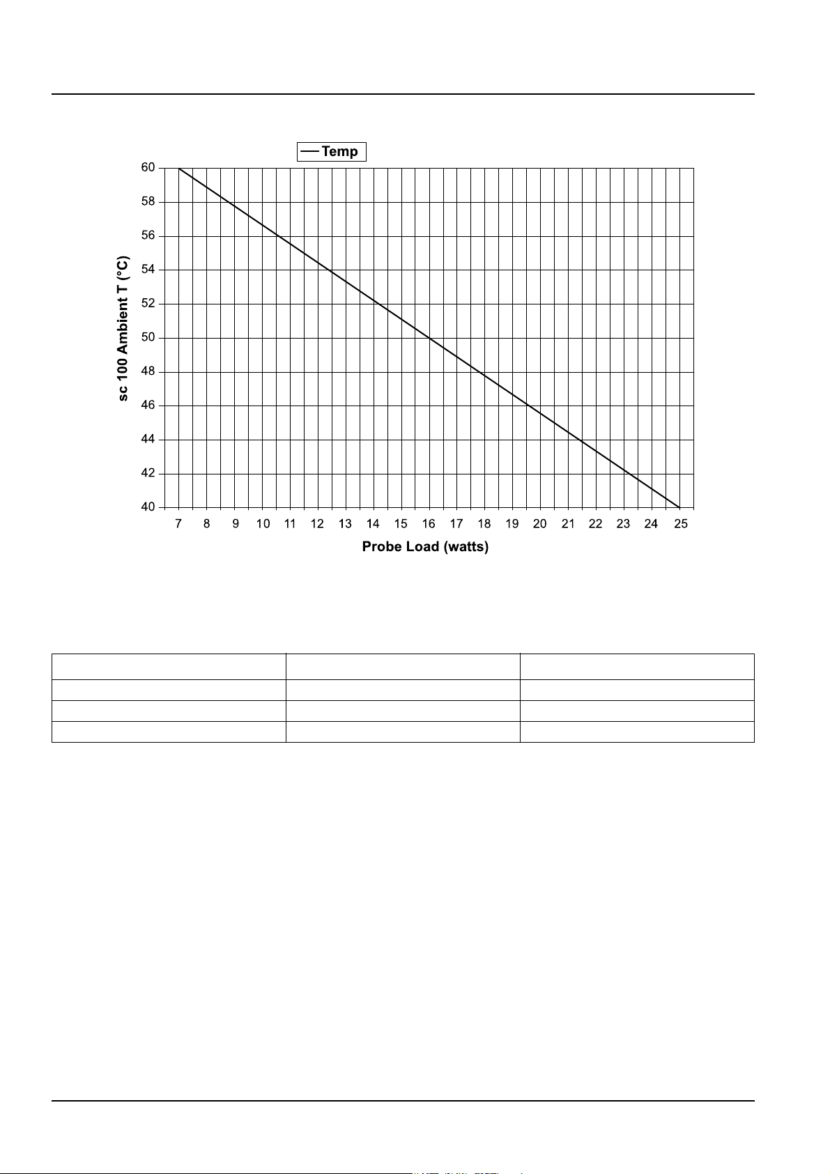
Figure 1 Maximum ambient temperature vs. probe load
Table 1 sc100 controller capacity
Controller operating temperature (°C) Power available (watts) Controller capacity
40 25 1 SS7 sc plus 5 watts for other devices
50 16 1 SS7 sc plus 4 watts for other devices
60 7 Out of power range for SS7 sc
6
Page 9
Specifications
Temp
58
56
54
52
50
48
46
sc 1000 Ambient T (°C)
44
42
40
38
20
22 24
26 28 30 32 34 36 38 40
42
46 48 50 52
44
54
56
Probe Load (watts)
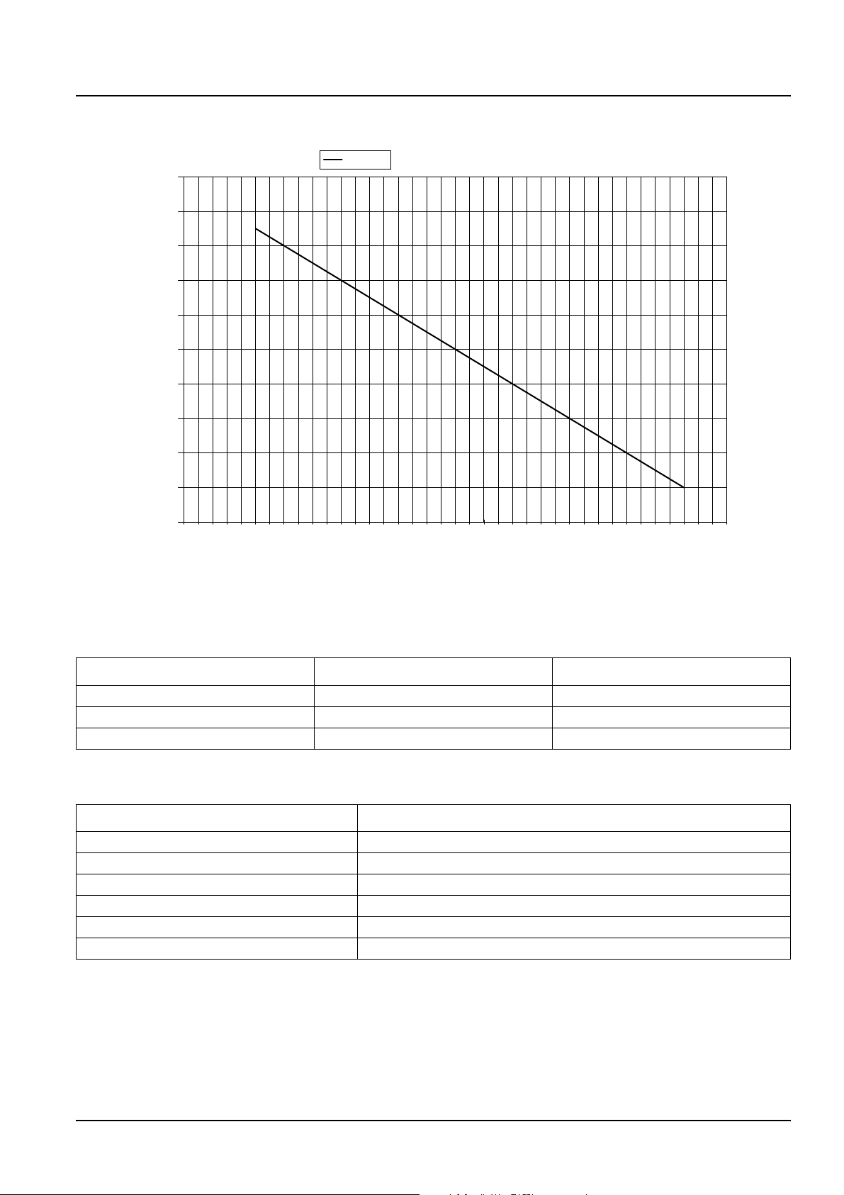
Figure 2 Maximum ambient temperature vs. probe load
Table 2 sc1000 controller capacity
Controller operating temperature (°C) Power available (watts) Controller capacity
40 55 2 SS7 sc plus 15 watts for other devices
50 35 2 SS7 sc plus 11 watts for other devices
55 25 1 SS7 sc plus 13 watts for other devices
Table 3 sc1000 component power consumption
Component Power consumption (watts)
Display module 10
Current output card 2.5 maximum load
Current input card 1.5
Relais card 1
Fieldbus module (Profibus) 2.5
Fieldbus module (Modbus) 0.5
58
7
Page 10

Visit us at www.hach.com
Page 11
Section 2 General information
2.1 Safety information
Please read this entire manual before unpacking, setting up or
operating this equipment. Pay attention to all danger and caution
statements. Failure to do so could result in serious injury to the
operator or damage to the equipment.
To ensure that the protection provided by this equipment is not
impaired, do not use or install this equipment in any manner other
than that specified in this manual.
2.1.1 Use of hazard information
DANGER
Indicates a potentially or imminently hazardous situation
which, if not avoided, could result in death or serious injury.
CAUTION
Indicates a potentially hazardous situation that may result in
minor or moderate injury.
Important Note: Information that requires special emphasis.
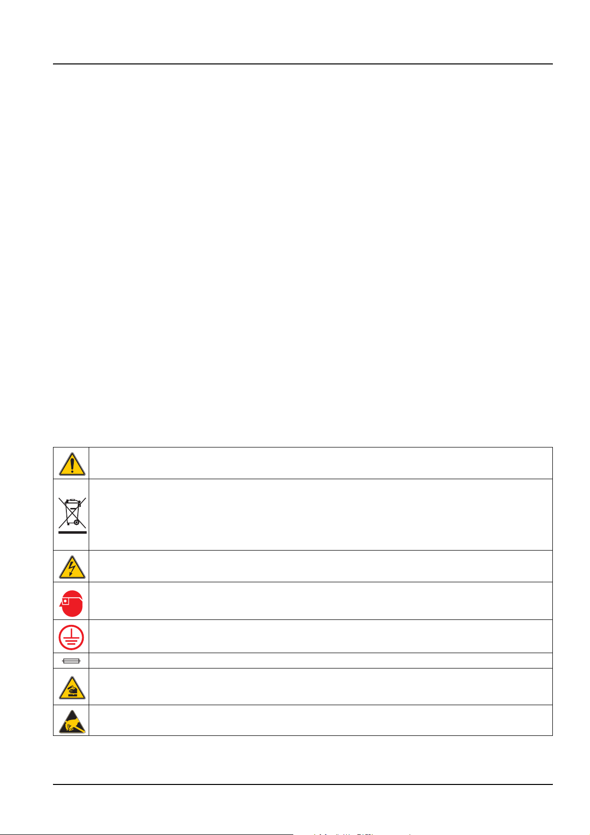
2.1.2 Precautionary labels
This symbol, if noted on the instrument, references the instruction manual for operation and/or safety information.
Electrical equipment marked with this symbol may not be disposed of in European public disposal systems after 12
August of 2005. In conformity with European local and national regulations (EU Directive 2002/96/EC), European
electrical equipment users must now return old or end-of life equipment to the Producer for disposal at no charge to
the user.
Note: For return for recycling, please contact the equipment producer or supplier for instructions on how to return
end-of-life equipment, producer-supplied electrical accessories and all auxiliary items for proper disposal.
This symbol, when noted on a product enclosure or barrier, indicates that a risk of electrical shock and/or
electrocution exists.
This symbol, if noted on the product, indicates the need for protective eye wear.
Note: Information that supplements points in the main text.
Read all labels and tags attached to the instrument. Personal injury
or damage to the instrument could occur if not observed. A symbol,
if noted on the instrument, will be included with a danger or caution
statement in the manual.
This symbol, when noted on the product, identifies the location of the connection for Protective Earth (ground).
This symbol, when noted on the product, identifies the location of a fuse or current limiting device.
This symbol, when noted on the product, identifies a risk of chemical harm and indicates that only individuals
qualified and trained to work with chemicals should handle chemicals or perform maintenance on chemical delivery
systems associated with the equipment.
This symbol, when noted on the product, indicated the presence of devices sensitive to Electro-static Discharge
(ESD) and indicated that care must be taken to prevent damage with the equipment.
9
Page 12
General information
2.2 General product information
2.2.1 Instrument description
The Surface Scatter® 7 sc (SS7 sc) Turbidimeter is a sensitive,
continuous-monitoring instrument designed for measuring turbidity
in fluids. The instrument design is based on the nephelometric
principle, where light scattered by particles suspended in the fluid is
measured to determine the relative amount of particulate matter in
the fluid. It meets all U.S. Environmental Protection Agency
(USEPA) design criteria, features an automatic-ranging digital
display and is capable of measuring turbidities from 0–9999 NTU.
Calibration is based on formazin, the primary turbidity reference
standard adopted by the APHA Standard Methods for the
Examination of Water and Wastewater and the USEPA. The
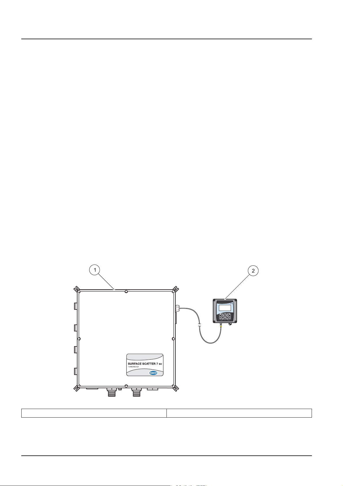
instrument consists of a control unit and a sample unit (Figure 3).
DANGER
The SS7 sc and SS7 sc-HST Turbidimeters are not designed
for use with samples that are flammable or explosive in nature.
If any sample solution other than water is used in this product,
test the sample/product compatibility to assure user safety
and proper product performance.
DANGER
The SS7 sc/sc controller platform product configuration is not
intended for installation in hazardous locations. See the
sc controller platform installation control drawing 58600-78 for
approved hazardous location sensors.
Figure 3 SS7 sc Turbidimeter
1 Sample unit 2 Control unit
10
Page 13

2.2.1.1 Controller
General information
The SS7 sc and SS7 sc-HST operate in conjunction with an sc100
controller. The controller enclosure houses the keypad, display,
microprocessor board and power supply components.
Operating controls and indicators are on the controller. The
controller is used to program the instrument for turbidity level alarm
set points and to perform diagnostic self-tests and
programming operations.
Sample turbidity is displayed continually by the digital display
during normal operation. Because of the automatic decimal point
positioning, no range selection is needed. Indicators of turbidity
level alarm conditions, certain critical system malfunctions or other
possible malfunctions are also on the controller.
Programmable alarm circuits provide three relay closures, both
normally open and normally closed, for selectable turbidity alarm
level set points. Set points can be programmed by the operator
anywhere within the overall range. The alarm circuits can be
programmed for Alarm, Feeder Control, Event Control, PWM
Control, Frequency Control and Warning. Refer to the sc100
manual for setup and use of these different settings. An alarm relay
can be programmed in the sc100 to control the optional Auto
Flush Kit.
2.2.1.2 Sample unit
The sc100 controller is designed to meet NEMA 4X water-tight
requirements. It is constructed of corrosion-proof materials. It is
suitable for indoor installation. Mounting hardware is included with
the sc100 to provide the capability to wall mount, pipe mount and
panel mount the controller without affecting the environmental
integrity of the case. Electrical access holes are sized for
½-in. conduit.
Sample flows through the sample unit (Figure 4) where sample
turbidity is measured. The sample unit enclosure contains all the
electronics for measuring the turbidity. A NEMA 12, corrosion-proof
case protects the optical components and hydraulics from industrial
environments and supplies the measurement signal to the control
unit. The case is designed for wall mounting with external
mounting blocks.
Hydraulic connections to the sample unit are at the bottom of the
enclosure. An air purge fitting is installed in the enclosure bottom.
Air purge is suggested to control condensation inside
the enclosure.
11
Page 14
General information
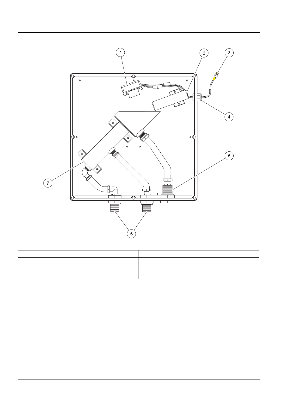
Figure 4 SS7 sc components
1 Detector assembly (Cat. No. 71221-00) 5 Bulkhead fitting, 1-in. NPT (Cat. No. 40355-00)
2 Light source assembly (Cat. No. 45004-00) 6 Bulkhead fittings, ¾-in. NPT (Cat. No. 40311-00)
3 To sc100 7 Turbidimeter body (Cat. No. 45002-00)
4 Cord grip (Cat. No. 61287-01)
12
Page 15
General information
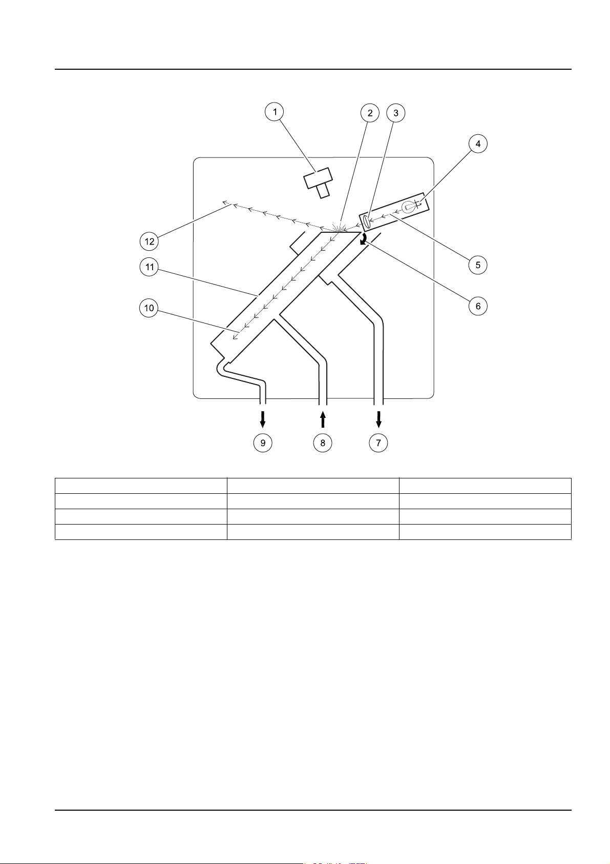
Figure 5 Optical diagram
1 Detector assembly 5 Light beam 9 Instrument drain
2 Scattered light 6 Over-flowing sample 10 Refracted light
3 Lens 7 Overflow drain 11 Turbidimeter body
4 Lamp 8 Sample in 12 Reflected light
2.2.2 Surface Scatter 7 sc High Sample Temperature
The Surface Scatter 7 sc High Sample Temperature Turbidimeter
(SS7 sc-HST) has been designed for high sample temperature. The
basic design and principle of operation are the same as the
standard SS7 sc model. Differences between the standard and
HST models will be noted in this manual where appropriate.
13
Page 16
General information
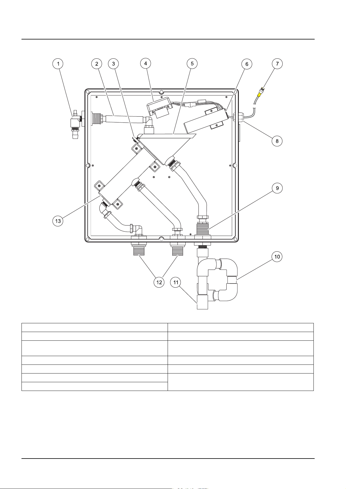
Figure 6 SS7 sc-HST components
1 Flow multiplier 8 Cord grip (Cat. No. 61287-01)
2 ¾-in. hose 9 Bulkhead fitting, 1-in. NPT (Cat. No. 40355-00)
3 Threaded disk (Cat. No. 40299-00) with ¼-in. screw
(Cat. No. 7858-11)
4 Detector assembly (Cat. No. 71221-00) 11 1-in. NPT gravity drain
5 Vent cover (Cat. No. 40294-00) 12 Bulkhead fittings, ¾-in. NPT (Cat. No. 40311-00)
6 Light source assembly (Cat. No. 45004-00) 13 Turbidimeter body (Cat. No. 45002-00)
7 To sc100
10 Drain trap
14
Page 17

Section 3 Installation
3.1 Basic installation overview
DANGER
Only qualified personnel should conduct the tasks described
in this section of the manual. The SS7 sc/sc controller product
configuration is not intended for installation in
hazardous locations.
The tasks described in this section requires individuals to be
technically knowledgeable of the associated dangers. Burns,
shock, eye damage, fire and chemical exposure may occur if this
work is not done by qualified personnel. Always review appropriate
Material Safety Data Sheets (MSDS) before working with
chemicals.
1. Unpack the SS7 sc or SS7 sc-HST Turbidimeter (section 3.2).
2. Review the environmental requirements and select the
mounting location (section 3.3.2 on page 17).
3. Mount the sample unit (section 3.3.3 on page 17).
4. Install the optional heat exchanger, if required (section 3.3.4 on
page 19).
3.2 Unpacking the instrument
5. Install the 3-way ball valve, if required (section 3.3.5 on
page 20).
6. Connect the sample in, body drain and overflow drain
(section 3.5 on page 21).
7. Connect the air purge valve (section 3.6 on page 24).
8. Connect the sample unit to the controller to supply power to the
system (section 3.7.2 on page 24).
1. Remove the instrument from the shipping carton.
2. Verify that no visible damage has occurred during shipment. Be
sure the following items are included in the carton:
• Sample unit
• Instruction manual
• Installation kit items (Figure 7)
Contact the manufacturer immediately to report missing or
damaged items.
15
Page 18
Installation
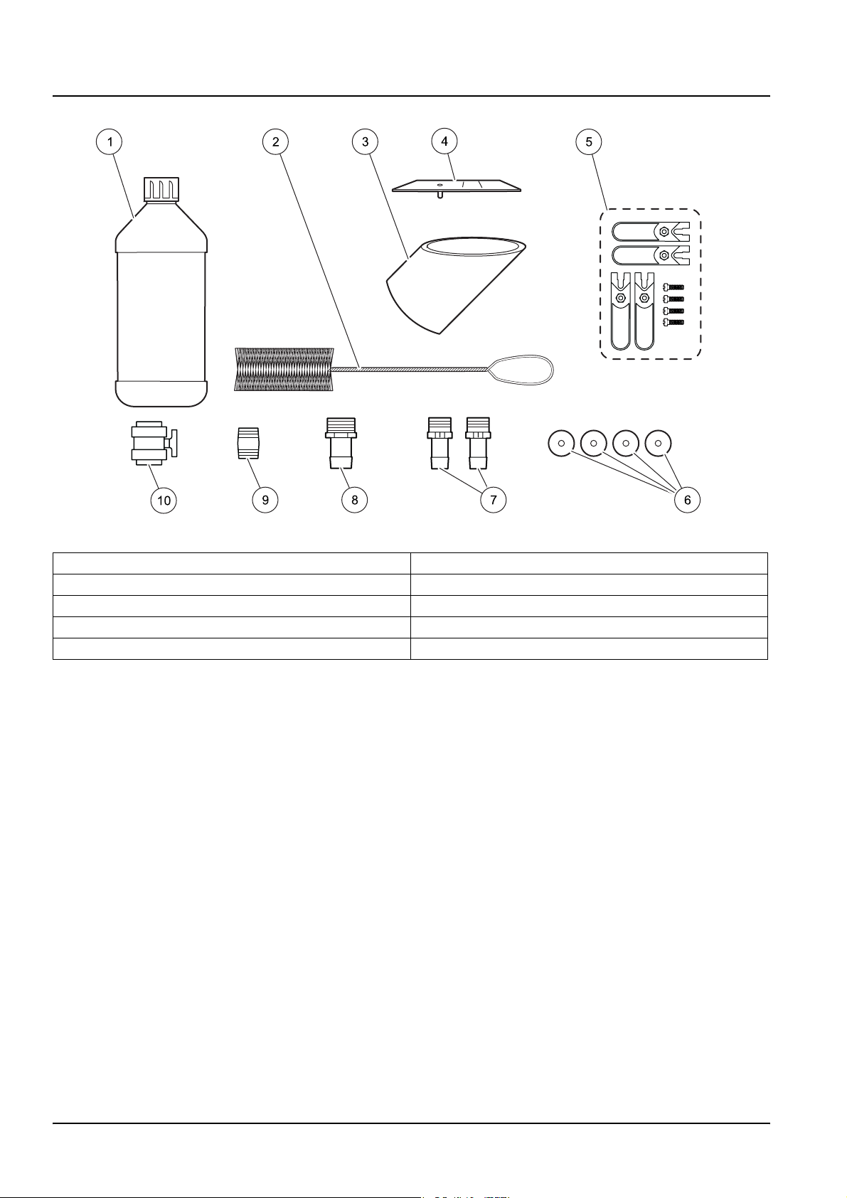
Figure 7 Installation kit items
1 Formazin stock solution, 4000 NTU, 500 mL 6 Washer, ¼ ID x 1.00 OD (4x)
2 Brush, cylinder, size 2 7 Adapter, barb fitting, ¾” NPT to ¾” ID hose barb (2x)
3 Calibration cup, SS7 sc 8 Adapter, barb fitting, 1” NPT to 1” ID hose
4 Light source alignment plate 9 Nipple, ¾” NPT
5 Wall mounting kit 10 Drain valve
1
See Section 8 Replacement parts and accessories on page 51.
1
16
Page 19

3.3 Mechanical installation
3.3.1 Environmental requirements
The SS7 sc and SS7 sc-HST enclosures are designed for
general-duty, indoor installation. Ambient temperatures within
specifications are allowed, but best performance will result if
temperature does not change rapidly. Do not mount in direct
sunlight. Shield from dripping water.
The controller enclosure is designed to protect the electronics from
typical conditions in water treatment and industrial facilities.
3.3.2 Selecting the installation location
Turbidimeters should always be located as close to the sampling
point as possible. The shorter the distance traveled by the sample
to the turbidimeter, the faster the turbidimeter can respond and
indicate changes in sample turbidity.
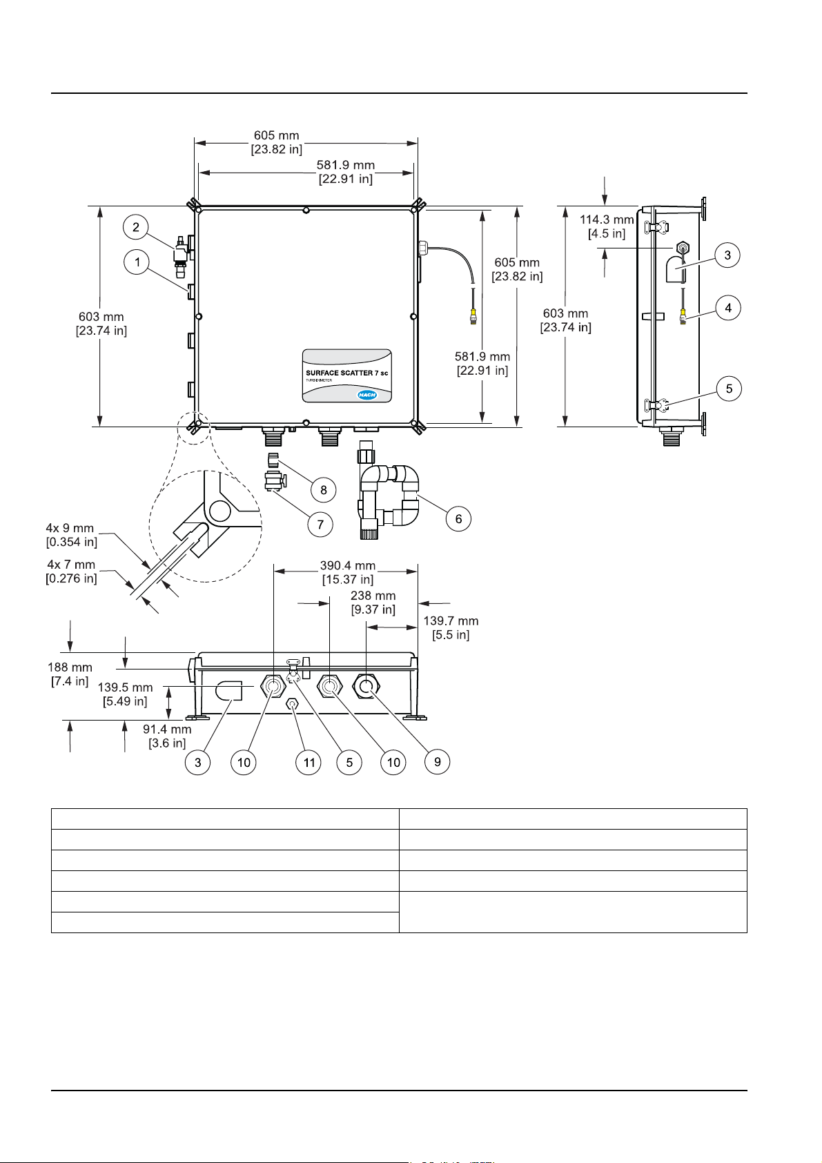
Dimensions and other installation information are shown in Figure 8
on page 18, Figure 9 on page 19 and Figure 10 on page 20. The
control and sample unit are designed for wall mounting. The
turbidimeter sensor must be mounted within six feet of the
controller unless an extension cable is used. Maximum cable length
is 9.6 m (31.5 ft).
Installation
3.3.3 Mounting the SS7 sc or SS7 sc-HST
1. To ensure proper performance, the sample unit must be level
(Figure 9 on page 19). Use a small level across the top opening
of the turbidimeter body to verify that the instrument does not
slope left-to-right or front-to-back.
2. Use one rubber washer (supplied) at each wall mounting block
between the block and the wall. Mounting blocks are secured to
the four corners of the sample unit to facilitate wall mounting
without affecting the integrity of the enclosure protection.
3. Attach the sample unit to the wall with four customer-supplied
mounting bolts.
17
Page 20
Installation
Figure 8 SS7 sc and SS7 sc-HST installation drawing
1 Door hinges (4x) 7 Ball valve
2 Flow multiplier (SS7 sc-HST only) 8 ¾-in. NPT nipple
3 Ventilator (2x) 9 1-in. NPTF bulkhead fitting
4 Cable assembly 10 ¾-in. NPTF bulkhead fitting
5 Enclosure door latch (4x) 11 Air purge fitting
6 Drain trap (SS7 sc-HST only)
18
Page 21

Installation
Figure 9 Instrument leveling
1 Level
3.3.4 Installing the optional heat exchanger
An optional heat exchanger (Cat. No. 48551-00) is available for the
SS7 sc-HST (Figure 10 on page 20). The heat exchanger reduces
sample temperatures that exceed the temperature requirements of
the instrument. It can reduce sample temperatures of up to 100 °C
but is not suitable for steam or super-heated water. A source of
cooling water is required. The heat exchanger is made of 316
stainless steel and has ¾” MNPT pipe connections. The large
plumbing connections help eliminate clogging.
• Allow adequate space below and to the right (latch) side of the
sample unit to make hydraulic connections.
• See Figure 10 on page 20 for installation dimensions.
• See Figure 12 on page 22 for heat exchanger connections.
19
Page 22

Installation
Figure 10 Heat exchanger dimensions
3.3.5 Installing the 3-way ball valves
3.4 Installing a sample line
CAUTION
Installation should be performed by qualified technical
personnel to ensure adherence to all applicable electrical and
plumbing codes.
Refer to the Auto Flush Kit Instruction Sheet (Cat. No. 46692-88)
for complete installation instructions.
Sample lines diameter must be appropriate for the sample type.
Choose a line size that minimizes lag time, but also minimizes
plugging with solids.
• Route the sample line as directly as possible.
• Using long or large diameter sample lines will result in a
significant lag time between actual process conditions and
instrument measurements.
• When larger diameter sample lines or long distances are
unavoidable, increase flow to the instrument and bypass
excess flow to the drain or back to process.
20
• Install sample line taps into larger process pipes to minimize
the chances of ingesting sediment from the pipe-line bottom or
air bubbles from the top. A tap projecting into the center of the
pipe is ideal. Figure 11 shows both good and poor methods of
installing a sample tap.
Page 23

Figure 11 Sampling techniques
1 Poor 5 Sediment (typical)
2 Sampling line to sample unit 6 Good
3 Sample flow 7 Best
4 Air (typical)
Installation
3.5 Connecting hydraulics
Note: When connecting the hydraulics to the bottom of the unit, hold the
¾-in. bulkhead adapters on the inside of the enclosure with the door open.
The sample in, body drain and overflow drain are connected to the
instrument as shown in Figure 5 on page 13. The sample inlet port
is fitted with a ¾” NPT female fitting with ¾” ID hose barb adapter
fitting. A ball valve is supplied with the instrument to drain the
turbidimeter body. Hose barb adapter fittings for sample in and both
drain fittings are also supplied.
A Bubble Trap/Head Regulator (Cat. No. 46680-00) is
recommended if the sample cannot be delivered bubble-free to the
analyzer. The device may also be used as to dampen fluctuations in
flow due to pulses from a pump and/or sample pressure.
Using the Bubble Trap/Head Regulator will increase response time
to changes in sample concentration. The increase in response time
may vary from 1–2 minutes at 2 L/min. For fastest response time,
use the highest flow practical for sample conditions. Higher flows
decrease the effectiveness of bubble removal. The need for fast
response time and bubble removal must be balanced for
optimum performance.
Install the Bubble Trap/Head Regulator so the overflow is at least
five inches above the top of the sample unit enclosure (Figure 12
on page 22). However, installation height can vary based on local
sample conditions and flow requirements. See the installation
instructions supplied with the Bubble Trap/Head Regulator for
more information.
21
Page 24

Installation
Figure 12 SS7 sc-HST plumbing diagram
1 Optional items 14 Sample unit
2 Bubble trap 15 sc100
3 3-way ball valve (Auto Flush Kit) 16 Customer supplied power on/off switch box (NEMA 4X)
required for agency compliance
4 Cooling water to drain 17 Power in for sc100
5 Cooling water out 18 ¾-in. NPT adapter (supplied)
6 Flow control valve 19 Drain Trap (Customer-supplied)
7 Sample in 20 1-in. NPT adapter (supplied)
8 Sample bypass during flush cycle 21 To drain
9 Cooling water in 22 ¼-in. air purge fitting (50 SCFH instrument air max)
10 Heat exchanger 23 Ball valve (supplied)
11 Electrical box connection 24 ¾-in. NPT nipple (supplied)
12 127 mm (5 in.) minimum 25 Customer supplied hose to drain
13 Customer supplied air for flow multiplier
A Sample during normal operation D Cooling water during auto flush
B Sample bypass during auto flush E Electrical
C Cooling water in normal operation F Drain
22
Page 25

Installation
Figure 13 SS7 sc plumbing diagram
1 Sample in 9 Power in for sc100
2 Flow control valve (recommended) 10 ¾-in. NPT nipple (supplied)
3 ¾-in.NPT x ¾-in. ID Hose Adapter
(supplied with bubble trap)
4 Bubble trap (optional) 12 ¼-in. air purge fitting (50 SCFH instrument air max)
5 127 mm (5 in.) minimum 13 1-in. NPT nipple (supplied)
6 Sample unit 14 ¾-in. NPT nipple (supplied)
7 sc100 15 To drain
8 Customer supplied power on/off switch box (NEMA 4X)
required for agency compliance
11 Ball valve (supplied)
16 ¾-in. ID hose (customer supplied)
23
Page 26

Installation
3.6 Connecting the air purge fitting
Air purge helps control condensation and corrosive vapors within
the sample unit and is recommended. Use dry instrument air only.
See Figure 12 and Figure 13 for installation details.
3.7 Electrical installation
3.7.1 Wiring safety information
When making any wiring connections to the instrument, the
following warnings and notes must be adhered to, as well as, any
warnings and notes found throughout the individual installation
sections. For more safety information refer to section 2.1 on
page 9.
DANGER
Always disconnect power to the sc controller when making
electrical connections.
3.7.1.1 Electrostatic discharge (ESD) considerations
Important Note: To minimize hazards and ESD risks, maintenance
procedures not requiring power to the analyzer should be
performed with power removed.
Delicate internal electronic components can be damaged by static
electricity, resulting in degraded instrument performance or
eventual failure.
The manufacturer recommends taking the following steps to
prevent ESD damage to your instrument:
• Before touching any instrument electronic components (such
as printed circuit cards and the components on them)
discharge static electricity by touching an earth-grounded metal
surface such as the chassis of an instrument or a metal conduit
or pipe.
• To avoid static electricity buildup and to keep it discharged,
wear a wrist strap connected by a wire to earth ground.
• To reduce static build-up, avoid excessive movement.
Transport static-sensitive components in anti-static containers
or packaging.
• Handle all static-sensitive components in a static-safe area.
If possible, use anti-static floor pads and work bench pads.
3.7.2 Connecting/wiring the SS7 sc or SS7 sc-HST to the sc100 controller
3.7.2.1 Attaching the SS7 sc with a quick-connect fitting
24
The SS7 sc/SS7 sc-HST cable is supplied with a keyed
quick-connect fitting for easy attachment to the controller
(Figure 14). Retain the connector cap to seal the connector opening
in case the cable must be removed. The original six-foot cable may
be extended by a maximum of 9.6 m (31.2 ft), see Replacement
parts and accessories on page 51.
Page 27

Installation
Figure 14 Attaching the SS7 sc/SS7 sc-HST using the quick-connect fitting
3.7.2.2 Hard-wiring the SS7 sc to the sc100 controller
1. Disconnect power to the controller if powered.
2. Open the controller cover.
3. Disconnect and remove the existing wires between the
quick-connect and terminal strip J5 (Figure 15).
4. Remove the quick-connect fitting and wires and install the
threaded plug on the opening to maintain the
environmental rating.
5. Cut the connector from the SS7 sc cable.
6. Strip the insulation on the cable back 1-inch. Strip ¼-in. of each
individual wire end.
7. Pass the cable through conduit and a conduit hub or a strain
relief fitting (Cat. No. 16664-00) and an available access hole in
the controller enclosure. Tighten the fitting.
8. Use of strain relief fitting other than Cat. No. 16664-00 may
result in a hazard. Use only the recommended strain
relief fitting to assure the continued NEMA 4X enclosure rating.
9. Reinstall the plug on the sensor access opening to maintain the
environmental rating.
10. Wire as shown in Table 4 and Figure 15.
11. Close and secure the cover.
25
Page 28

Installation
Table 4 Wiring the SS7 sc at terminal block J5
Terminal number Terminal designation Wire color
1Data (+) Blue
2 Data (–) White
3 Service request No connection
4 +12 V dc Brown
5 Circuit common Black
6 Shield Shield (gray wire in existing quick disconnect fitting)
Figure 15 Hard-wiring the SS7 sc
1 From SS7 sc 2 Disconnect power
26
Page 29

Section 4 System startup
4.1 General operation
1. Plug the SS7 sc/SS7 sc-HST into the unpowered controller by
aligning the orientation tab on the cable connector with the
channel in the controller connector.
2. Push in and turn the threaded collar to secure the connection.
Tug gently to check the connection.
3. After all plumbing and electrical connections have been
completed and checked, supply power to the system.
4. Ensure the sample unit door is securely latched when power is
applied, since dark readings are measured at this time. If power
is applied while the door is open, cycle the power with the door
closed. The dark readings are measured again one hour after
the power-up.
5. The first time a controller is powered up, a language selection
menu will appear. Select the correct language from the
displayed options.
6. Following language selection and upon power-up, the controller
will search for connected sensors. The display will show the
main measurement screen.
4.2 Starting sample flow
1. Start sample flow through the instrument by opening the
sample supply valve.
2. Allow the turbidimeter to run long enough for the tubing and
body to become completely wetted and the reading on the
display to stabilize. One to two hours or longer may be required
initially for complete stabilization.
3. Allow measurements to become stable through adequate
conditioning before completing instrument settings or
performing calibrations.
27
Page 30

Visit us at www.hach.com
Page 31

Section 5 Operation
5.1 Sensor setup
5.1.1 Configuring the bubble reject
When a sensor is initially installed, the sensor name will be
displayed. To change the sensor name refer to the
following instructions:
1. From the Main Menu, select SENSOR SETUP and confirm.
2. If multiple sensors are attached to the controller, choose
SELECT SENSOR>SS7 SETUP and confirm.
3. Select CONFIGURE and confirm.
4. Select EDIT NAME and edit the name. Confirm or cancel to
return to the Sensor Setup menu
Bubble Reject eliminates high measurements that are likely due to
air trapped in the sample.
1. From the Main Menu, select SENSOR SETUP and confirm.
2. Highlight the appropriate sensor if more than one sensor is
attached and confirm.
5.1.2 Configuring the signal average
3. Select CONFIGURE and confirm.
4. Select BUBBLE REJECT and confirm.
5. Select YES or NO and confirm.
• When NO is selected, all measurements within the Signal
Average window will be averaged to determine the
measured value.
• Choosing YES eliminates a percentage of the high values
and averages the remaining values to determine the
measured value.
The Signal Average function creates a running average of the
previous 6, 30, 60 or 90 seconds or no averaging, depending on the
selected signal average.
1. From the Main Menu, select SENSOR SETUP and confirm.
2. Highlight the appropriate sensor if more than one sensor is
attached and confirm.
3. Select CONFIGURE and confirm.
4. Select SIGNAL AVG and confirm.
5. Select the signal average time interval and confirm.
29
Page 32

Operation
5.2 Sensor data logging
The controller provides two data logs (one for each sensor) and two
event logs (one for each sensor). The data logs store the
measurement data at selected intervals. The event log stores a
variety of events that occur on the devices such as configuration
changes, alarms and warning conditions. The data logs are stored
in a packed binary format and the event logs are stored in a CSV
format. The logs can be downloaded through the digital network
port, service port or the IrDA port. DataCom (Cat. No. 59256-00 or
download from www.hach.com) is needed for downloading logs to a
computer. If the datalogging frequency is set to 15 minute intervals,
the instrument can continue to store data for approximately
six months.
1. From the Main Menu, select SENSOR SETUP and confirm.
2. Highlight the appropriate sensor if more than one sensor is
attached and confirm.
3. Select CONFIGURE and confirm.
4. Select the datalog interval (
2 minutes, 5 minutes, 10 minutes, 15 minutes, 30 minutes, 60 minutes
or 4 hours
). Confirm.
5 seconds, 30 seconds, 1 minute,
5.3 Sensor diagnostics menu
SELECT SENSOR
ERROR LIST See section 7.1 on page 47.
WARNING LIST See section 7.2 on page 47.
5.4 Sensor setup menu
SELECT SENSOR (if more than one sensor is attached)
CALIBRATE
PERFORM CAL Calibration using 4000 NTU stock solution
VERIFICATION Perform a verification, set the pass/fail criteria and view the verification history.
0 ELECTRONICS Zero electronics
CAL HISTORY
CONFIGURE
BUBBLE REJECT Choose Yes or No to enable/disable bubble reject. Default: Yes
SIGNAL AVG
MEAS UNITS
EDIT NAME
SET RESOLUTION Set the number of significant digits to display. Default is one significant digit.
DATALOG INTRVL
View the last 12 entered calibrations. Confirm to move to the next history entry. See section 5.6
on page 36 for more information.
Choose no averaging or specify the amount of time for signal averaging. Available options are:
no averaging, 6 sec., 30 sec., 60 sec. or 90 sec. Default is 30 seconds.
Select the appropriate measurement units to display. Choose from mg/L, NTU, FTU and NO
UNITS. Default: NTU
Enter up to a 12-digit name in any combination of symbols and alpha or numeric characters.
Confirm when the entry is complete. The name will be displayed on the status line above the
measurement value on the main display. Default is SS7.
Choose the amount of time between saving data points to the data log. Default: 15 min.;
Options: 5 seconds, 30 seconds, 1 minute, 2 minutes, 5 minutes, 10 minutes, 15 minutes,
30 minutes, 60 minutes or 4 hours.
30
Page 33

5.4 Sensor setup menu (continued)
DIAG/TEST
INST STATUS Displays the software and hardware versions.
SERIAL NUMBER Displays the serial number of the sensor.
INT TEMP Displays the internal temperature of the sensor electronics in °C.
DEFAULT SETUP Restores the sensor factory default settings. Calibration is not affected.
POWER CHECK Displays the electrical statistics for the sensor.
SERVICE MODE
SERVICE DIAG Accessible with service password only.
Allows SS7 sc to be run in normal or service mode. Analog outputs can be in ACTIVE, HOLD or
TRANSFER mode. Data logging is disabled. Protected by MAINTENANCE password.
5.5 Sensor calibration and verification
5.5.1 Standardization and calibration
DANGER
To become familiar with handling precautions, dangers and
emergency procedures, always review the Material Safety Data
Sheets prior to handling containers, reservoirs and delivery
systems that contain chemical reagents and standards.
Protective eye wear is always recommended when contact
with chemicals is possible.
Operation
5.5.2 Calibration
Note: Due to the ease with which the calibration cylinder method
calibration can be performed, better accuracy can be maintained by
performing a calibration at monthly intervals instead of the standardization
check. Periodic calibration with a formazin primary standard is
recommended for best absolute accuracy.
The manufacturer recommends calibrating the Surface Scatter 7 sc
instrument at least every three months or any time the light source
is replaced or adjusted. If calibration is performed with a formazin
standard, refer to section 5.5.2.1 on page 32.
1. From the Main Menu, select SENSOR SETUP and confirm.
2. If multiple sensors are attached to the controller, choose
SELECT SENSOR>SS7 SETUP and confirm.
3. Select CALIBRATE and confirm.
4. Select PERFORM CAL and confirm. Select the available
Output Mode (Active, Hold or Transfer) and confirm.
5. Enter the STD VALUE and confirm. Confirm to continue.
6. Follow the display prompt and place standard into the
calibration cup. Close the sensor door and confirm to continue.
7. The TURB value displayed is the standard value determined
using the gain from the previous calibration. Confirm to accept
and continue with the calibration.
31
Page 34

Operation
5.5.2.1 Calibration cylinder method
8. If no selection is made for a set period of time, the screen will
prompt to remix the standard to avoid a change in the value of
the standard.
a. Open the SS7 sc and remix the standard.
b. Close the door and confirm to continue.
9. Confirm to calibrate. When the calibration is completed
successfully, confirm to accept the calibration.
10. Enter the initials of the user performing the calibration
and confirm.
Note: After confirmation of return to measurement mode, the instrument
will equilibrate for 2 minutes before the output mode changes. Instrument
measurements will show on the display, but the value will flash and a “OUT
MODE WARN” warning will display until the 2-minute equilibration period
is complete.
A calibration cylinder and a 500-mL bottle of 4000 NTU formazin
primary standard solution are included for convenient calibration of
the SS7 sc. After the formazin standard is added to the cylinder, the
instrument is set to the value of the standard.
1. Prepare the formazin standard solution at the desired NTU
value. The 4000-NTU standard supplied with the instrument
can be used at full strength and only requires mixing (by
inverting the bottle repeatedly). If a dilution of the 4000-NTU
standard is desired, the manufacturer recommends it be no
lower than 300 NTU. Dilutions must be made just prior to use.
Dilute formazin solutions are unstable and should be discarded
when calibration is complete. Use filtered sample or
demineralized water for dilution.
2. Turn off sample flow to the instrument and drain the
turbidimeter body. Insert the calibration cylinder into the top of
the body (Figure 16 on page 33).
a. Select the PERFORM CAL menu entry and confirm.
b. Select the Active, Hold or Transfer output mode
and confirm.
c. Edit the standard value and confirm.
3. Follow the display prompts and pour the formazin standard
solution into the cylinder, allowing it to overflow. Only allow the
solution to stand long enough to allow bubbles on or near the
surface to dissipate.
4. Close the sample unit door tightly. Confirm to continue.
32
5. The TURB value displayed is the standard value determined
using the gain from the previous calibration. Confirm to accept
and continue with the calibration.
6. If no selection is made for a set period of time, the screen will
prompt to remix the standard to avoid a change in the value of
the standard.
a. Open the SS7 sc and remix the standard.
b. Close the door and confirm to continue.
Page 35

Operation
7. Confirm to calibrate. When the calibration is completed
successfully, the display will show GOOD CAL! and the new
calibration gain value. Confirm to accept the calibration.
8. Follow the prompt and enter the initials of the user performing
the calibration. Confirm.
9. The controller will prompt for NEW BASELINE. Confirm to
establish a new baseline or press
10. Remove the calibration cylinder from the body. The instrument
is now calibrated.
11. Close the drain valve and restore the sample flow. If no
verification is done, the display will prompt to return to
measurement mode. Confirm to continue measurements.
BACK to exit.
Figure 16 Installing the calibration cylinder
1 Detector assembly 3 Light source assembly
2 Calibration cylinder 4 Turbidimeter body
5.5.2.2 Comparison method
The comparison method transfers the calibration of a laboratory
instrument to the on-line instrument and the practice is approved by
the EPA and Standard Methods for the Examination of Water and
Wastewater. Calibration by comparison should not be used if
sample turbidity is less than 2 NTU.
Before performing this method, make sure the laboratory
turbidimeter used is calibrated properly with primary turbidity
standards according to manufacturer directions. Sample cells for
the laboratory instrument must be free from dirt, fingerprints and
scratches. For greater convenience, the laboratory instrument
should be moved to a location close to the on-line unit(s) to be
33
Page 36

Operation
calibrated. Take a grab sample from the on-line instrument drain or
sample inlet line and immediately measure its turbidity in the
laboratory instrument. If the on-line instrument reading is off by
more than 5%, use the calibration procedure detailed in
section 5.5.2 on page 31 to input the new standard value. If this
calibration method is used, it is not necessary to use the
calibration cylinder.
5.5.2.3 Calibration failure
If gain criteria for the calibration are not met, the screen will display
BAD CAL! Confirm to repeat the calibration.
5.5.3 Setting the verification baseline
When the SS7 sc has been successfully calibrated, a baseline can
be determined using standardization plates. The standardization
plates are composed of opaque backing, a plate glass covering and
a center filling of Gelex, a stable secondary turbidity standard. The
standardization plates are not calibrated when shipped from the
factory. The value of the plate is determined after calibration and
stored internally in the SS7 sc.
by reading the plate value and comparing it to the value
following calibration.
The calibration can be verified later
Important Note: Always verify calibration with the same
standardization plate that was used to establish the baseline. The
manufacturer recommends assigning a serial number (up to 4
characters) to each plate. The serial number can be marked on the
back of the plate.
1. Perform a calibration (section 5.5.2).
2. Confirm to perform a baseline using a standardization plate.
3. The serial number for the last standardization plate used will
appear on the display. Confirm to accept or enter the serial
number of the plate to be used and confirm.
4. Follow the controller prompts:
a. Remove the calibration cylinder and wipe off the top of the
sample cylinder.
b. Place the standardization plate on top of the sample
cylinder so that the light beam strikes the center of the
plate. Note the orientation of the plate and always place it
in the same position when using it to check standardization.
c. Close the door to eliminate stray light. Confirm to continue.
5. When the measured value becomes stable, confirm to establish
an expected value for the plate.
34
Note: Future measured values will be compared to the stored
expected value. If the established PASS criteria are not met, a new
calibration should be performed.
Page 37

5.5.4 Instrument verification
Operation
6. Open the SS7 sc to remove the plate. Restart the sample flow
and close the door. Confirm to return the instrument to
measurement mode.
Note: After confirmation of return to measurement mode, the instrument
will equilibrate for 2 minutes before the output mode changes. Instrument
measurements will show on the display, but the value will flash and a “OUT
MODE WARN” warning will display until the 2-minute equilibration period
is complete.
Instrument verification is intended as a simple check to ensure
SS7 sc functionality between calibrations. Verifications should be
performed on a monthly basis using a manufacturer-provided
standardization plate.
A verification directly after calibration is used to establish the
baseline. Any verification afterwards, until the next calibration, that
uses the same verification standard will reference the recorded
value from the baseline verification as the “expected” value. In
order for the verification to pass, the measured value should be
within the limits set by the Pass/Fail Criteria of the baseline value.
Before starting the verification, read section 5.5.3.
1. From the Main Menu, select SENSOR SETUP and confirm.
2. If multiple sensors are attached to the controller, choose
SELECT SENSOR>SS7 SETUP and confirm.
3. Select CALIBRATE and confirm.
4. Select VERIFICATION and confirm.
5. Select PERFORM VER and confirm.
6. The serial number on the standardization plate to be used for
verification should match the serial number listed on the VALID
SN screen. Confirm to accept the displayed serial number.
Important Note: If the serial numbers do not match, a verification
baseline (section 5.5.3) must be established before verification can
be performed.
7. Select the available Output Mode (Active, Hold or Transfer)
from the list box and confirm.
8. Position the plate on top of the sample cylinder:
a. Shut down the sample flow and wipe off the top of the
sample cylinder.
b. Place the standardization plate on top of the sample
cylinder so that the light beam strikes the center of the
plate. Note the orientation of the plate and always place it
in the same position when using it to check standardization.
c. Close the door to eliminate stray light. Confirm to continue.
35
Page 38

Operation
5.5.4.1 Care of standardization plates
9. When the displayed turbidity value is stable, confirm to select
the measured reading. After confirming the reading:
• GOOD VER! will be displayed if the verification is good,
with an option to continue or to abort. Confirm to continue.
Enter the operator initials and confirm.
• BAD VER! will be displayed if the verification is bad, with an
option to repeat or exit. To repeat the verification, confirm to
return to the VALID SN screen (step 6).
10. Open the SS7 sc to remove the plate. Restart the sample flow
and close the door. Confirm to return the instrument to
measurement mode.
Note: After confirmation of return to measurement mode, the instrument
will equilibrate for 2 minutes before the output mode changes. Instrument
measurements will show on the display, but the value will flash and a “OUT
MODE WARN” warning will display until the 2-minute equilibration period
is complete.
Clean standardization plates to remove fingerprints, dust and dirt.
• Clean plates using water and dry with a clean,
lint-free cloth.
• Do not use abrasive cleaners or cleaning solvents.
Store the plates in a clean, dry place to prevent scratching or
damage. Replace the plates if they become scratched or broken.
5.6 Calibration and verification history
The calibration and verification history logs contain information on
the last 12 calibrations and the last 12 verifications. The calibration
history log shows the gain value, the time and date of the
calibration and the initials of the operator performing verification.
Note: Restoring default settings from the DIAG/TEST menu will return the
turbidimeter to its non calibration state (gain = 1.0) but it will not remove the
previous calibration history from memory.
The calibration history log is accessed from the Calibrate menu.
The verification history log is accessed from the Verification menu
(a submenu of the Calibrate menu).
Each verification history entry shows the serial number of the
verification device, the value of the verification standard, the time
and date of the verification and the initials of the operator
performing the verification.
To view calibration history:
1. From the Main Menu, select SENSOR SETUP and confirm.
36
2. If multiple sensors are attached to the controller, choose
SELECT SENSOR>SS7 SETUP and confirm.
3. Select CALIBRATE and confirm.
4. Select CAL HISTORY and confirm. The most recent calibration
will be displayed on the screen.
Page 39

Operation
5. Confirm to view the previous calibrations. After scrolling
through all 12 histories, the display will return to the calibration
menu level.
To view verification history:
1. From the Main Menu, select SENSOR SETUP and confirm.
2. If multiple sensors are attached to the controller, choose
SELECT SENSOR>SS7 SETUP and confirm.
3. Select CALIBRATE and confirm.
4. Select VERIFICATION and confirm.
5. Select VER HISTORY and confirm. The most recent
verification will be displayed on the screen.
6. Confirm to view previous verifications. After scrolling through all
12 histories, the display will return to the calibration menu level.
To view baseline history:
1. From the Main Menu, select SENSOR SETUP and confirm.
2. If multiple sensors are attached to the controller, choose
SELECT SENSOR>SS7 SETUP and confirm.
3. Select CALIBRATE and confirm.
4. Select VERIFICATION and confirm.
5. Select BASELINE HIST and confirm. The most recent baseline,
including the Gelex plate serial number and expected value,
will be displayed on the screen.
6. Confirm to view previous verifications. After scrolling through all
12 histories, the display will return to the calibration menu level.
When the instrument is received from the factory, there will be one
entry for the calibration and verification history information. As
calibrations and verifications are performed, the history information
will grow until there are 12 entries.
When the log is full, the newest entry is stored and the oldest entry
in the log is deleted.
37
Page 40

Operation
5.7 Operating the SS7 sc-HST
• If condensation forms in the enclosure, increase the air
pressure (and flow) by increasing the air pressure setting of the
pressure regulator for the flow multiplier.
• Make sure the bubble trap is working. Bubbles on the surface
of the liquid will cause incorrect readings.
• If deposits accumulate inside the unit, wash the inside with
warm water spray.
• The vent cover at the top of the turbidimeter body (Figure 6 on
page 14, item 5) can be removed for cleaning if necessary.
Loosen the light source before removing the cover. Check the
alignment of the light after reinstalling the cover using the new
alignment plate included in the kit (section 6.4.1 on page 40).
Make sure the cover sits flat on top of the slant tube
when installed.
• Calibrate the instrument using the calibration cup and formazin
as described in section 5.5.2 on page 31.
Note: Do not operate the instrument without the cover. Do not operate the
instrument if the flow multiplier is not working.
38
Page 41

Section 6 Maintenance
DANGER
Only qualified personnel should conduct the tasks described
in this section of the manual.
The nature of tasks described in this section of the manual requires
individuals to be technically knowledgeable of the associated
dangers. Burns, shock, eye damage, fire and chemical exposure
may occur if this work is not done by qualified personnel. Always
review appropriate Material Safety Data Sheets (MSDS) before
working with chemicals.
6.1 Scheduled maintenance
Scheduled periodic maintenance requirements of the SS7 sc
Turbidimeter are minimal. Standardization checks and calibration
are the primary requirements. Several other activities should be
performed on a regular basis, but the schedule for these may
depend on the installation and sample.
6.2 Removing a sensor from the system
Prior to physically removing a sensor from the system, record all
user defined settings such as relays, signal averaging, etc. Turn off
power to the sc100 and SS7 sc, then disconnect the sensor at
the controller.
6.3 Installing a sensor on the system
To return the system to normal operation following a software
upgrade or sensor repair, perform the following procedure:
1. Detach all sensors from the sc100 controller.
2. From the Main Menu, press the
TEST/MAINT and confirm.
3. Use the
4. Remove attached sensors by selecting the corresponding serial
number or select “All”.
5. Power down the sc100 controller, then attach the sensor(s)
to be used.
Note: Clean sensors before installing on the system.
6. Supply power to the sc100 controller. The system will
initialize automatically.
DOWN key to highlight
DOWN key to scroll to SCAN SENSORS and confirm.
39
Page 42

Maintenance
6.3.1 Cleaning
Sediment may collect in the turbidimeter body and on the overflow
weir. Algae may also form. The turbidimeter body should be drained
and flushed—on a schedule determined by visual inspection—to
remove accumulated sediment. Algae can be removed with a large
bottle brush and a sterilizing solution such as dilute chlorine bleach.
Samples containing large amounts of settleable solids may cause
frequent accumulation of solids in the turbidimeter body. To
minimize cleaning frequency, the analyzer can be operated with the
drain ball valve partially or completely open and the sample flow
increased accordingly to provide continuous flushing of solids from
the turbidimeter body. If the drain is left partially open, the ball valve
supplied should be replaced with a valve designed for flow control.
Operating the ball valve in a partially open position may damage
the valve or cause plugging of the drain line.
When used in conjunction with the Auto-flush Kit (section 8.2 on
page 51), the flush cycle feature may be used to operate a solenoid
valve to divert sample and provide a periodic clear water flush.
The inside enclosure of the SS7 sc can be washed down with warm
water spray if deposits accumulate inside the unit. The vent cover
at the top of the SS7 sc-HST turbidimeter body can also be
removed for cleaning as necessary.
6.4 Unscheduled maintenance
6.4.1 Lamp replacement
Note: Loosen the light source to remove or install the vent cover on the
SS7 sc-HST. Use the alignment plate included in the unit to check the
alignment of the light after installing the cover. Make sure the cover sits flat
on top of the slant tube when installed.
Important Note: Disconnect power to the instrument before
removing any cover. To reduce the possibility of ESD damage to
the equipment, avoid contact with electrical components. All
replacement components must meet or exceed original equipment
specifications to maintain applicable safety standards and
certifications and ensure proper instrument performance.
The lamp is located in the light source assembly block in the
sample unit. It comes with attached leads terminated in a two-pin
connector. The lamp is replaced as follows:
1. Set the power switch in the control unit to off. Disconnect power
to the sc100 controller.
2. Open the sample unit door. Disconnect the lamp cable at
the connector.
3. Remove the two screws that secure the lamp source assembly
to the back plate. Remove the lamp source assembly
(Figure 17).
40
4. Remove the four screws securing the end plate to the light
source assembly housing. Remove the end plate with gasket,
the notched spacer and the lamp.
Page 43

Maintenance
5. Wipe the replacement lamp clean to remove any dust and
fingerprints. Fingerprints left on the glass bulb can permanently
damage the lamp. Install the lamp in the light source block.
6. Slide the notched spacer over the lamp cable with the notch
away from the lamp base. Route the lamp cable through the
notches. Install the lamp and spacer into the end of the housing
with the spacer notch aligned with the notch in the housing.
7. Install the end plate using the two screws removed in step 3.
8. Install the assembled light source assembly in the sample unit
using the two screws removed in step 2. Connect the lamp
cable connector.
9. Using the alignment template supplied with the turbidimeter,
verify that the light source assembly is positioned properly
as follows:
a. Be sure the lamp door is closed tightly. Apply power to the
sc100 controller. Wait for the display to show the current
turbidity reading before continuing.
b. Install the calibration cylinder in the top of the turbidimeter
body (Figure 16 on page 33).
c. Place the alignment template on top of the calibration
cylinder with the guide pin down and against the flat notch
on the inside of the cylinder (Figure 18). The back edge of
the template should be against the sample unit back plate.
d. Check the position of the lamp image on the alignment
template surface. It should fall on the target area so the
center of the beam is centered between the lines
(Figure 18).
e. If the light source assembly needs adjustment, loosen the
two mounting screws enough to adjust the position of the
lamp image. Tighten when aligned properly.
10. Calibrate the instrument as described in section 5.5 on
page 31.
41
Page 44

Maintenance
Figure 17 Lamp replacement
1 Lamp cable 6 Spacer
2 End plate 7 Housing
3 Notched spacer 8 Light source assembly
4 Back plate 9 Lamp
5 Base
42
Page 45

Maintenance
Figure 18 Alignment details
1 Flat notch 6 Light source assembly
2 Alignment template 7 Mounting screws
3 Calibration cylinder 8 Target area
4 Turbidimeter body 9 Adjust light source to align light beam in target area
5 Install calibration cylinder and alignment template
6.4.2 Light source assembly maintenance
No maintenance of the light source assembly is normally necessary
beyond changing the lamp. The lamp, several lenses, apertures
and other components are located in the light source housing. If
these components are removed for any reason, they must be
installed exactly as they were removed. Placing any of the
components in the wrong position or orientation can cause
measurement errors and lack of alignment. Figure 19 illustrates the
correct installation and orientation of the components. If difficulty is
experienced in reassembly, contact Technical Support for
assistance. Refer to Section 9 on page 53.
43
Page 46

Maintenance
Figure 19 Light source assembly
1 Shield assembly (Cat. No. 45299-00) 10 Spacer, light source (Cat. No. 45039-00)
2 Wavy washer (2x) (Cat. No. 45042-00) 11 Gasket (Cat. No. 45033-00)
3 Medium aperture (Cat. No. 45044-00) 12 End plate (Cat. No. 45032-00)
4 Large aperture (Cat. No. 45045-00) 13 Body (Cat. No. 45027-00)
5 Retaining ring (Cat. No. 45041-00) 14 Large spacer (Cat. No. 45037-00)
6 Lens holder (Cat. No. 45040-00) 15 Small lens (Cat. No. 31465-00)
7 Small aperture (Cat. No. 45043-00) 16 Small spacer (4x) (Cat. No. 45038-00)
8 Large lens (2x) (Cat. No. 44114-00) 17 Screws (8x) (Cat. No. 5584-11)
9 Medium spacer (Cat. No. 45036-00)
6.4.3 Detector assembly replacement
The detector assembly, listed as a replacement item in section 8.1
on page 51, is a sealed unit that is replaced entirely (Figure 20).
1. Write down the controller setup for all analog outputs and/or
2. Turn off the controller and disconnect it from power.
3. Disconnect the detector cable from the controller. Unscrew the
4. Open the SS7 sc enclosure door. Using a blunt object (¼-inch
5. Pull the detector cable through the strain relief. Open the cable
44
relays used with the SS7 sc.
nut (Figure 20, item 8) and remove it from the disconnected
detector cable.
diameter or less, e. g. the blunt end of a pen) push on the
bushing from the inside of the enclosure until it is free of the
strain relief and clamping fingers. Remove the grommet from
the detector cable.
clamps (Figure 20, item 3) and remove the cable.
Page 47

Maintenance
6. Remove the two screws securing the detector assembly to the
wall of the SS7 sc enclosure. Remove the complete
detector assembly (Figure 20, item 1).
7. Use the two screws removed in step 6 to secure the new
detector to the wall of the SS7 sc enclosure. Secure the cable
with the cable clamps.
8. Thread the detector cable through the strain relief. Replace the
split grommet (note the orientation in Figure 20) onto the
detector cable. At the clamping fingers, rotate the grommet
counter-clockwise while pushing the grommet back into place
in the strain relief.
9. Thread the nut onto the detector cable and secure onto the
strain relief.
10. Close the SS7 sc enclosure door. Attach the detector cable to
the controller.
11. Apply power to the controller and turn it on. The controller will
prompt the user that the SS7 cannot be found. The old detector
serial number will be displayed.
12. Use the arrow keys to select the old detector serial number and
remove it. The controller will then install the new
detector assembly.
13. Establish the setup for all analog outputs and/or relays to be
used with the SS7 sc. Use the settings recorded in step 1.
14. Calibrate the instrument (section 5.5 on page 31).
45
Page 48

Maintenance
Figure 20 Detector assembly replacement
1 Detector assembly (Cat. No. 71221-00) 6 Clamping fingers
2 Light source assembly power connector 7 Bushing
3 Cable clamp 8 Nut
4 Blunt object 9 Detector assembly cable
5 Strain relief
46
Page 49

Section 7 Troubleshooting
7.1 Error Codes
Errors are indicated by a flashing measurement value and a
flashing warning icon. Errors are defined in Table 5.
1. From the Main Menu, select SENSOR DIAG and confirm.
2. If multiple sensors are attached to the controller, choose
SELECT SENSOR>SS7 SETUP and confirm.
3. Select ERROR LIST and confirm. All active errors will display.
Table 5 Error codes
DIsplayed error Definition
ADC FAIL
LAMP FAIL The light source has failed. See section 6.4.1 on page 40 for lamp replacement instructions.
FLASH FAIL Datalog and event log will not work.
7.2 Warnings
The ADC has failed. Try cycling power. If cycling power does not work, replace the detector
assembly (Cat. No. 71221-00).
Warnings are indicated by a flashing measurement value and a
flashing warning icon. Warnings are defined in Table 6.
1. From the Main Menu, select SENSOR DIAG and confirm.
2. If multiple sensors are attached to the controller, choose
SELECT SENSOR>SS7 SETUP and confirm.
3. Select WARNING LIST and confirm. All active warnings
will display.
Table 6 Warning Codes
Warning
Number
1 DARK WARNING
2 TEMP WARNING
3 DATA LOG FULL
4 EVENT LOG FULL
5 5 VOLT WARN Monitored voltage is outside the range of 4.5–5.5 V.
6 VIN WARN
7 LAMP VOLT WARN Monitored voltage is outside the range of 3.96–4.48 V.
Displayed Warning Definition/Resolution
Dark reading detects too much light. Close the SS7 sc enclosure and perform
ZERO ELECTRONICS (under the CALIBRATION menu).
Sensor head internal temperature is higher than specified. Contact the
Technical Support Department. (> 70 °C)
Sensor data log is full. No additional data will be logged until sensor log is
downloaded into controller memory.
Sensor data log is full. No additional data will be logged until sensor log is
downloaded into controller memory.
Monitored instrument input voltage from sc100 is outside the range of
9.08–14.3 V. Check cables. Make sure only one SS7 sc is connected to sc100
and if any other probe is connected it can only draw 4 watts maximum.
8 LAMP CURR WARN Monitored current is outside the range of 1.67–2.75 Amps.
9 OUTPUT MODE WARN
10 AC UPDATE FAIL The application code update failed.
11 EXT FLASH FAIL External copy of the application code has failed. Self recovery should occur.
Activated when the sensor is not in normal measurement mode (such as when
in calibration or verification mode).
47
Page 50

Troubleshooting
Table 6 Warning Codes (continued)
Warning
Number
12 INT FLASH FAIL Internal copy of the application code has failed. Self-recovery should occur.
13 ENGLISH ONLY
14 VREF WARN ADC voltage reference is out of specification.
15 SERVICE WARN SS7 sc is currently in service mode
Displayed Warning Definition/Resolution
English only device driver file. Update the device driver with the latest version.
Table 7 presents sensor warnings displayed in the Event Log,
possible causes and corrective actions.
Table 7 General Troubleshooting
Sensor Error
or Warning
LAMP FAIL
Low Readings
VIN FAIL
ADC FAIL
DARK WARNING
Possible Cause Corrective Action
Lamp burned out Replace the lamp. See section 6.4.1 on page 40.
Lamp unplugged Restore connection
+12 V connection loose at controller Restore connection
Dislodged lamp Reinstall lamp
Bad circuit board in turbidimeter head Contact the Technical Support Department.
Detector coated/dirty
Lens coated/dirty Clean the lens using isopropyl alcohol and a cotton swab.
Obstructed light path Remove obstruction
See LAMP FAIL causes above See LAMP FAIL corrective actions above
Loose connection at sc100 Tighten connection of cable at sc100
SS7 sc to sc100 cable too long
Fluctuation in voltage Turn instrument power off and back on.
Bad detector assembly Replace detector assembly (Cat. No. 71221-00).
Fluctuation in voltage Turn instrument power off and back on.
Bad detector assembly Replace detector assembly (Cat. No. 71221-00).
Light Leak—SS7 sc enclosure door is
open during Power Up or Zero
Electronics
Bad detector Assembly Replace detector assembly (Cat. No. 71221-00).
See section 6.3.1 on page 40.
Contact the Technical Support Department.
Make sure that if an extension cable is used, only one is
present and is no longer than 7 meters (approximately
30 feet).
Make sure the door is closed, then perform ZERO
ELECTRONICS in the CALIBRATION MENU.
48
Page 51

Table 8 presents additional malfunctions which may not be
recorded in the Event Log.
Table 8 Additional malfunctions not recorded in the event log
Symptom Possible cause Corrective action
Continuous underrange
Continuous overrange
Erratic readings
High readings
The calibration standard was either
improperly prepared or was unstable at
the time the calibration was accepted.
The calibration standard was either
improperly prepared or was unstable at
the time the calibration was accepted.
Inadequate bubble removal from
sample
Dirty instrument
Calibration standard was low
Flow rate is too high causing bubbles
Verify the accuracy of calibration standards and calibrate
the instrument. See Low Readings in Table 7.
Verify the accuracy of calibration standards and
recalibrate the instrument.
Verify the accuracy of calibration standards and
recalibrate the instrument.
Increase the signal averaging time to a longer interval.
Make sure the Bubble Reject feature is turned on.
Slow the flow of sample into the instrument.
Clean the instrument.
Check the value and expiration date on the
calibration standard
Verify the flow is within specifications
Recalibrate the instrument.
Troubleshooting
7.3 Event codes
Events are automatically invoked to document major actions during
normal instrument operation. Event codes are not displayed on
controller and must be downloaded from the event log using Data
Com software. Troubleshooting actions are provided in Table 7 on
page 48.
Table 9 Event log list
Event Event # Data1 Data2 Data3
Bubble reject change 0
Signal avg 1
Data log interval change 2
Power on 3 — — —
Calibration 4 Std Gain Operator
Verification 5 Expected Value Meas Value Operator
Dark event 6 A/D counts — —
Temperature 7 Present Min Max
Volt warn 8 Vin 5V Vref
Lamp warn event 9 Lamp V Lamp I —
A2D fail event 10 — — —
Lamp fail 11 Lamp V Lamp I —
Output mode change 12
0 = OFF
1= ON
0 = 1, 1 = 6, 2 = 30,
3 = 60, 4 = 90
0 = 5 sec, 1 = 30 sec,
2 = 1 min, 3 = 2 min,
4 = 5 min, 6 = 15 min,
7 = 30 min, 8 = 1 hr,
9 = 4 hr
0 = Normal, 1 = Active
2 = Hold, 3 = Transfer
——
——
——
——
49
Page 52

Troubleshooting
Table 9 Event log list (continued)
Event Event # Data1 Data2 Data3
Baseline 13 Serial Number Expected Operator
AC update start 14 — — —
AC update done 15 — — —
AC update fail 16 — — —
AC internal fail 17 — — —
AC external fail 18 — — —
Flash erase 19 — — —
DD update 20 — — —
Service mode 21 0 = Off, 1 = On — —
Example of event log download using DataCom
15:00 01/09/06 BUBBLE REJECT 0 1
1/9/2006 15:00 BUBBLE REJECT 0 0
1/9/2006 15:00 SIGNAL AVG 1 2
1/9/2006 15:00 SIGNAL AVG 1 1
1/9/2006 15:00 DATALOG INTRVL 2 9
1/9/2006 15:01 OUT MODE EVENT 12 1
1/9/2006 15:01 CALIBRATION 4 2100 1.51 G7
1/9/2006 15:01 BASELINE EVENT 13 7 2090.4 G7
1/9/2006 15:02 OUT MODE EVENT 12 2
1/9/2006 15:02 VERIFICATION 5 7 2090.4 2091.1 GS7
7.4 Data log
Measured data is automatically logged based on the setting of the
data log interval. If, however, there is a calibration or verification
being performed, the data log will be interrupted since the values of
the measurements do not represent the normal process. The data
log interval in the following example is set at 15 minutes.
Example of data log download using DataCom
Serial Number: FFFFFFFFFFFF
Device ID: 26
Manufacture ID: 0
50
Time Channel 1
1/18/2006 12:15 2009.04
1/18/2006 12:30 2009.71
1/18/2006 12:45 2010.316
1/18/2006 13:00 2009.096
Page 53

Section 8 Replacement parts and accessories
8.1 Replacement parts
Description Cat. No.
Surface Scatter® 7 sc Installation Kit:
Adapter, barb fitting, ¾” NPT to ¾” ID hose barb (2x) 40439-00
Adapter, barb fitting, 1” NPT to 1” ID hose 40372-00
Brush, cylinder, size 2 687-00
Calibration cup, SS7 sc 45021-00
Drain Valve 45073-00
Formazin Stock Solution, 4000 NTU, 500 mL 2461-49
Light Source Template 45076-00
Nipple, ¾” NPT 31551-00
Washer, ¼ ID x 1.00 OD (4x) 44173-00
Wall Mounting kit 44247-00
Light Source Shield Assemblies (2x) 45299-00
Detector Assembly 71221-00
Lamp Assembly, Surface Scatter 7 sc 45034-00
Manual DOC026.52.00769
Quick Reference Document DOC016.52.00769
Tubing Replacement Kit 46691-00
8.2 Accessories
Description Cat. No.
Auto Flush Kit (120V) 46692-12
Auto Flush Kit (220V) 46692-22
Bubble Trap/Head Regulator 46680-00
Cable Extension for Sensor, 7.6 m (25 ft) 57960-00
DataCom (CD-rom) 59256-00
Formazin Stock Solution, 4000 NTU, 500 mL 2461-49
Heat Exchanger Unit (Sample cooler) 48551-00
Latch, replacement, SS6 44993-00
Manual, SS7 sc, English DOC026.52.00769
Manual, SS7 sc, Chinese DOC026.80.00769
Manual, SS7 sc, Japanese DOC026.81.00769
Manual, SS7 sc, Korean DOC026.84.00769
Power Cord, 125 VAC, 10A, 1.83 m (6 ft) 46306-00
Power Cord, 250 VAC, 10A, 1.83 m (6 ft) 46308-00
StablCal, 400 NTU, 500 mL 71216-49
Standardization Plate Kit, uncalibrated 23513-00
Sun Shield, sc100 Controller LZ961.54
Upgrade Kit, Converting Standard SS7 sc to a SS7 sc-HST (High Sample Temperature) 45000-43
51
Page 54

Visit us at www.hach.com
Page 55

Section 9 Contact
HACH LANGE GMBH
Willstätterstraße 11
D-40549 Düsseldorf
Tel. +49 (0)2 11 52 88-0
Fax +49 (0)2 11 52 88-143
info@hach-lange.de
www.hach-lange.com
DR. BRUNO LANGE AG
Juchstrasse 1
CH-8604 Hegnau
Tel. +41(0)44 9 45 66 10
Fax +41(0)44 9 45 66 76
info@hach-lange.ch
www.hach-lange.ch
HACH LANGE APS
Åkandevej 21
DK-2700 Brønshøj
Tel. +45 36 77 29 11
Fax +45 36 77 49 11
info@hach-lange.dk
www.hach-lange.dk
HACH LANGE LTD
Pacific Way
Salford
GB-Manchester, M50 1DL
Tel. +44 (0)161 872 14 87
Fax +44 (0)161 848 73 24
info@hach-lange.co.uk
www.hach-lange.co.uk
HACH LANGE FRANCE
S.A.S.
33, Rue du Ballon
F-93165 Noisy Le Grand
Tél. +33 (0)1 48 15 68 70
Fax +33 (0)1 48 15 80 00
info@hach-lange.fr
www.hach-lange.fr
HACH LANGE AB
Vinthundsvägen 159A
SE-128 62 Sköndal
Tel. +46 (0)8 7 98 05 00
Fax +46 (0)8 7 98 05 30
info@hach-lange.se
www.hach-lange.se
HACH LANGE LTD
Unit 1, Chestnut Road
Western Industrial Estate
IRL-Dublin 12
Tel. +353(0)1 46 02 5 22
Fax +353(0)1 4 50 93 37
info@hach-lange.ie
www.hach-lange.ie
HACH LANGE SA
Motstraat 54
B-2800 Mechelen
Tél. +32 (0)15 42 35 00
Fax +32 (0)15 41 61 20
info@hach-lange.be
www.hach-lange.be
HACH LANGE S.R.L.
Via Riccione, 14
I-20156 Milano
Tel. +39 02 39 23 14-1
Fax +39 02 39 23 14-39
info@hach-lange.it
www.hach-lange.it
DR. BRUNO LANGE GES.
MBH
Industriestraße 12
A-3200 Obergrafendorf
Tel. +43 (0)27 47 74 12
Fax +43 (0)27 47 42 18
info@hach-lange.at
www.hach-lange.at
DR. LANGE NEDERLAND
B.V.
Laan van Westroijen 2a
NL-4003 AZ Tiel
Tel. +31(0)344 63 11 30
Fax +31(0)344 63 11 50
info@hach-lange.nl
www.hach-lange.nl
HACH LANGE S.L.U.
C/Araba 45, Apdo. 220
E-20800 Zarautz/Guipúzcoa
Tel. +34 9 43 89 43 79
Fax +34 9 43 13 02 41
info@hach-lange.es
www.hach-lange.es
HACH LANGE LDA
Av. do Forte nº8
Fracção M
P-2790-072 Carnaxide
Tel. +351 214 253 420
Fax +351 214 253 429
info@hach-lange.pt
www.hach-lange.pt
HACH LANGE KFT.
Hegyalja u. 7-13.
H-1016 Budapest
Tel. +36 (06)1 225 7783
Fax +36 (06)1 225 7784
info@hach-lange.hu
www.hach-lange.hu
HACH LANGE D.O.O.
Fajfarjeva 15
SI-1230 Domžale
Tel. +386 (0)59 051 000
Fax +386 (0)59 051 010
info@hach-lange.si
www.hach-lange.si
HACH LANGE SP.ZO.O.
ul. Opolska 143 a
PL-52-013 Wrocław
Tel. +48 (0)71 342 10-83
Fax +48 (0)71 342 10-79
info@hach-lange.pl
www.hach-lange.pl
HACH LANGE S.R.L.
str. Aviator Teodor Iliescu
nr.37,
Sector 1
RO-011672, Bucuresti
Tel. +40 (0)21 2 08 95 78
Fax +40 (0)21 2 08 95 78
info@hach-lange.ro
www.hach-lange.ro
ΗΑCH LANGE E.Π.Ε.
Αυλίδος 27
GR-115 27 Αθήνα
Τηλ . +30 210 7771700
Fax +30 210 7480122
info@hach-lange.gr
www.hach-lange.gr
HACH LANGE S.R.O.
Lešanská 2a/1176
CZ-141 00 Praha 4
Tel. +420 272 12 45 45
Fax +420 272 12 45 46
info@hach-lange.cz
www.hach-lange.cz
HACH LANGE
8, Kr. Sarafov str.
BG-1164 Sofia
Tel. +359 (0)2 963 44 54
Fax +359 (0)2 866 04 47
info@hach-lange.bg
www.hach-lange.bg
HACH LANGE S.R.O.
Roľnícka 21
SK-831 07 Bratislava –
Vaj nory
Tel. +421 (0)2 4820 9091
Fax +421 (0)2 4820 9093
info@hach-lange.sk
www.hach-lange.sk
HACH LANGE SU
ANALİZ SİSTEMLERİ
LTD. ŞTİ.
Hilal Mah. 75. Sokak
Arman Plaza No: 9/A
TR-06550 Çankaya/ANKARA
Tel. +90 (0)312 440 98 98
Fax +90 (0)312 442 11 01
bilgi@hach-lange.com.tr
www.hach-lange.com.tr
53
Page 56

Section 10 Limited warranty
HACH LANGE GmbH warrants that the product supplied is free of material and manufacturing defects
and undertakes the obligation to repair or replace any defective parts at zero cost.
The warranty period for instruments is 24 months. If a service contract is taken out within 6 months of
purchase, the warranty period is extended to 60 months.
With the exclusion of the further claims, the supplier is liable for defects including the lack of assured
properties as follows: all those parts that, within the warranty period calculated from the day of the
transfer of risk, can be demonstrated to have become unusable or that can only be used with significant
limitations due to a situation present prior to the transfer of risk, in particular due to incorrect design, poor
materials or inadequate finish will be improved or replaced, at the supplier's discretion. The identification
of such defects must be notified to the supplier in writing without delay, however at the latest 7 days after
the identification of the fault. If the customer fails to notify the supplier, the product is considered
approved despite the defect. Further liability for any direct or indirect damages is not accepted.
If instrument-specific maintenance and servicing work defined by the supplier is to be performed within
the warranty period by the customer (maintenance) or by the supplier (servicing) and these requirements
are not met, claims for damages due to the failure to comply with the requirements are rendered void.
Any further claims, in particular claims for consequential damages cannot be made.
Consumables and damage caused by improper handling, poor installation or incorrect use are excluded
from this clause.
HACH LANGE GmbH process instruments are of proven reliability in many applications and are
therefore often used in automatic control loops to provide the most economical possible operation of the
related process.
To avoid or limit consequential damage, it is therefore recommended to design the control loop such that
a malfunction in an instrument results in an automatic change over to the backup control system; this is
the safest operating state for the environment and the process.
54
Page 57

Section 11 Certification
Product Safety
Immunity
Hach Company certifies this instrument was tested thoroughly,
inspected and found to meet its published specifications when it
was shipped from the factory.
The Model sc100 with SS7 sc or SS7 sc-HST Sensor has been
tested and is certified as indicated to the following
instrumentation standards:
UL 61010A-1 Listed by ETL (cETLus safety mark)
CSA C22.2 No. 61010.1 Certified by ETL (cETLus safety mark)
Certified by Hach Co. to EN 61010-1 Amds. 1 & 2 (IEC1010-1) per
73/23/EEC, supporting test records by Intertek Testing Services.
This equipment was tested for Industrial level EMC per:
EN 61326 (EMC Requirements for Electrical Equipment for
Measurement, Control and Laboratory Use)
Supporting test records and compliance certification by
EMC:
Hach Company.
per 2004/108/EC
Emissions
Standards include:
IEC 1000-4-2:1995 (EN 61000-4-2:1995) Electro-Static
Discharge Immunity (Criteria B)
IEC 1000-4-3:1995 (EN 61000-4-3:1996) Radiated RF
Electro-Magnetic Field Immunity (Criteria A)
IEC 1000-4-4:1995 (EN 61000-4-4:1995) Electrical Fast
Transients/Burst (Criteria B)
IEC 1000-4-5:1995 (EN 61000-4-5:1995) Surge (Criteria B)
IEC 1000-4-6:1996 (EN 61000-4-6:1996) Conducted
Disturbances Induced by RF Fields (Criteria A)
IEC 1000-4-11:1994 (EN 61000-4-11:1994) Voltage Dip/Short
Interruptions (Criteria B)
Additional immunity Standard/s include:
ENV 50204:1996 Radiated Electro-Magnetic Field from Digital
Telephones (Criteria A)
This equipment was tested for Radio Frequency Emissions
as follows:
Per 2004/108/EC EMC: EN 61326:1998 (Electrical Equipment for
measurement, control and laboratory use—EMC requirements)
Class “A” emission limits. Supporting test records by Hewlett
Packard, Fort Collins, Colorado Hardware Test Center (A2LA #
0905-01) and certified compliance by Hach Company.
Standards include:
EN 61000-3-2 Harmonic Disturbances Caused by Electrical
Equipment
55
Page 58

Certification
EN 61000-3-3 Voltage Fluctuation (Flicker) Disturbances
Caused by Electrical Equipment
Additional Emissions Standard/s include:
EN 55011 (CISPR 11) Class “A” emission limits
Canadian Interference-causing Equipment Regulation, IECS-003, Class A
Supporting test records and compliance certification by
Hach Company.
This Class A digital apparatus meets all requirements of the
Canadian Interference- Causing Equipment Regulations.
Cet appareil numÈrique de la classe A respecte toutes les
exigences du RËglement sur le matÈriel brouilleur du Canada.
FCC PART 15, Class “A” Limits
Supporting test records and compliance certification by
Hach Company.
This device complies with Part 15 of the FCC Rules. Operation is
subject to the following two conditions:
(1) this device may not cause harmful interference, and (2) this
device must accept any interference received, including
interference that may cause undesired operation.
Changes or modifications to this unit not expressly approved by the
party responsible for compliance could void the user's authority to
operate the equipment.
This equipment has been tested and found to comply with the limits
for a Class A digital device, pursuant to Part 15 of the FCC Rules.
These limits are designed to provide reasonable protection against
harmful interference when the equipment is operated in a
commercial environment. This equipment generates, uses, and can
radiate radio frequency energy and, if not installed and used in
accordance with the instruction manual, may cause harmful
interference to radio communications. Operation of this equipment
in a residential area is likely to cause harmful interference, in which
case the user will be required to correct the interference at his own
expense. The following techniques of reducing the interference
problems are applied easily.
1. Disconnect the Controller from its power source to verify that it
is or is not the source of the interference.
2. If the Controller is connected into the same outlet as the device
with which it is interfering, try another outlet.
56
3. Move the Controller and SS7 sc sensor away from the device
receiving the interference.
4. Reposition the device receiving the interference.
5. Try combinations of the above.
Page 59

Appendix A Modbus register
Tag Name Register # Data Type Length R/W Description
TURB 40001 Float 2 R Measured turbidity value
TURB INT 40003 Unsigned Integer 1 R Integer turbidity value
TURB INT X 100 40004 Unsigned Integer 1 R Integer turbidity * 100
SENSOR NAME 40005 String 6 R/W Sensor name or location
BUBBLE REJECT 40011
SIGNAL AVG 400121 Unsigned Integer 1 R/W
DATALOG INTRVL 400131 Unsigned Integer 1 R/W
RESOLUTION 40014 Unsigned Integer 1 R/W
P/F CRITERIA 400151 Unsigned Integer 1 R/W
TURB UNIT 40016 Unsigned Integer 1 R/W Turb units (0=mg/L:7=NTU;42=FTU)
SERVICE MODE 400181 Unsigned Integer 1 R/W
SERIAL NUMBER 40021 String 6 R Instrument serial number
CODE VERSION 40027 Float 2 R Software version
DD Firmware 40029 Unsigned Integer 1 R Device driver firmware version
DD CONTENT 40030 Unsigned Integer 1 R Device driver content version
HW VERSION 40031 Unsigned Integer 1 R Hardware version of pc board
TEMP 40032 Float 2 R Temperature measurement in Celsius
DARK 40034 Unsigned Integer 2 R Dark turbidity A/D counts.
RAW TURB 40036 Float 2 R
TURB COUNTS 40038 Unsigned Integer 2 R Turbidity A/D counts
TEMP MAX 40040 Float 2 R Maximum temperature
TEMP MIN 40042 Float 2 R Minimum temperature
LAMP V 40044 Float 2 R Lamp voltage
LAMP CURR 40046 Float 2 R Lamp current (amps)
Plus 5V 40048 Float 2 R Plus five volt measurement
INPUT V 40050 Float 2 R Input voltage (~12V)
VREF 40052 Float 2 R Voltage reference measurement (2.5V)
CAL GAIN 40067 Float 2 R
INITIALS 40083 String 2 R Initials used for the latest calibration
LAST CAL DATE 40085 Time2 2 R Time of the latest calibration
CAL VALUE 40087 Float 2 R
1
Unsigned Integer 1 R/W Bubble reject status (0=OFF; 1=ON)
Signal average (0=1; 1=6sec;
2=30sec;3=60sec;4=90sec)
Datalog interval
(0=5sec;1=30sec;2=1min;3=2min;4=5min;6=10
min;7=15min;8=30min;9=60min, 10=4hr)
Maximum number of decimal places (0=xxxxx,
1=xxxx.x, 2=xxx.xx)
Pass / Fail criteria for verification. (1 to 10
percent)
Used to determine if the instrument is in the
service mode (0 = disabled; 1= enabled)
Turbidity value with dark offset and
gain applied.
Calibration gain factor - used to convert A/D
counts to turbidity
The standard value used for the latest
calibration
1
In order to write to these tags, write 46478 to register 49938
57
Page 60

Visit us at www.hach.com
Page 61

Appendix B Theory of operation
B.1 SS7 sc principle of operation
The Surface Scatter 7 sc Turbidimeter is a sensitive and precise
instrument designed to measure the light scattered by particles
suspended in the sample fluid. The sample flows up through the
turbidimeter body at a rate between 1 and 2 liters per minute (¼ to
½ gallon per minute). As the fluid spills over the top of the
turbidimeter body, a stable, flat surface of fluid forms and becomes
the measuring surface.
Because there is no contact between the fluid being analyzed and
any of the optical surfaces, the instrument can monitor even highly
turbid samples without frequent cleaning. Electrically and
mechanically, the Surface Scatter 7 sc Turbidimeter has been
constructed to ensure reliable operation in adverse environments.
The lamp, powered by a regulated voltage source, provides a high
intensity beam of light that is adjusted to strike the fluid surface at
an angle. Most of the light striking the surface of the fluid is either
reflected into the upper left hand corner of the cabinet and
absorbed, or refracted down into the turbidimeter tube (Figure 4 on
page 12). A small amount of the light is scattered by the particles
suspended in the fluid. Light scattered at 90 degrees from the
incident beam is detected by the detector assembly. The electronic
signal generated by the detector assembly is directly related to the
concentration of particles suspended in the fluid.
Directing the light beam at the fluid surface at an angle and placing
the detector assembly directly over the point where the light enters
the fluid is a very important design feature. Because the light is
scattered at or near the surface, only a minimum amount of
scattered light is absorbed by the fluid before it reaches the
detector assembly. Therefore, the amount of light scattered will
increase with increasing turbidity, regardless of how high the
turbidity becomes. This allows the instrument to measure very high,
as well as very low, levels of turbidity.
B.2 SS7 sc-HST principle of operation
The SS7 sc-HST instrument is designed for high temperature
samples, or in applications where a significant difference between
the sample temperature and the ambient temperature causes
condensation and fogging in the unit. The SS7 sc-HST functions in
the same manner as the SS7 sc, but accommodates samples of
higher temperature and a moist air removal system has
been added.
The moist air removal system contains an air flow multiplier that
creates a vacuum to draw moisture away from the sample tube and
remove the moisture from the enclosure. The moisture removal
system requires the customer to provide a source of air pressure,
such as compressed air, shop air, or an on-site air compressor. The
air line is connected to the top of the flow multiplier
(Figure 5, item 1).
59
Page 62

Visit us at www.hach.com
Page 63

Page 64

 Loading...