

Page 1

DOC023.52.00117
SONATAX sc
User manual
04/2012, Edition 3A
© HACH-LANGE GmbH, 2006, 2010, 2012. All rights reserved. Printed in Germany
Page 2

Page 3

Table of contents
Section 1 Technical data ........................................................................................................................................ 5
Section 2 General information ............................................................................................................................... 7
2.1 Safety information .............................................................................................................................................. 7
2.1.1 Use of hazard information ........................................................................................................................ 7
2.1.2 Precautionary labels ................................................................................................................................. 7
2.2 General sensor information................................................................................................................................ 8
2.2.1 Property rights note .................................................................................................................................. 8
2.2.2 Usage areas ............................................................................................................................................. 8
2.3 Device overview................................................................................................................................................. 8
2.4 Functional principle ............................................................................................................................................ 9
Section 3 Installation ............................................................................................................................................ 11
3.1 Unpack sensor ................................................................................................................................................. 11
3.1.1 Handling of the immersed probe ............................................................................................................ 11
3.2 Connect sensor to an sc controller .................................................................................................................. 11
3.2.1 Connect sensor with quick connection ................................................................................................... 11
3.3 Function test .................................................................................................................................................... 12
3.4 Install sensor.................................................................................................................................................... 13
3.4.1 Select the measurement location and pre-set the device....................................................................... 13
3.4.1.1 Determine the distance to the tank edge ....................................................................................... 15
3.4.1.2 Determine measurement location .................................................................................................. 15
3.4.2 Installation of the sensor......................................................................................................................... 18
3.5 Advanced settings............................................................................................................................................ 18
Section 4 Operation .............................................................................................................................................. 23
4.1 Use of the sc controller .................................................................................................................................... 23
4.2 Sensor data logging ......................................................................................................................................... 23
4.3 Sensor setup.................................................................................................................................................... 23
4.3.1 Change of the sensor name ................................................................................................................... 23
4.4 SENSOR STATUS menu................................................................................................................................. 23
4.5 SENSOR SETUP menu ................................................................................................................................... 23
Section 5 Maintenance ......................................................................................................................................... 27
5.1 Maintenance tasks ........................................................................................................................................... 27
5.2 Wiper change................................................................................................................................................... 27
5.3 Cleaning tasks ................................................................................................................................................. 28
Section 6 Troubleshooting................................................................................................................................... 29
6.1 Operating state LED ........................................................................................................................................ 29
6.2 Error messages................................................................................................................................................ 29
6.3 Warnings.......................................................................................................................................................... 30
6.4 SLUDGE DOCTOR, (diagnostic software for SONATAX sc)........................................................................... 30
Section 7 Replacement parts and accessories ................................................................................................ 31
7.1 Replacement parts........................................................................................................................................... 31
7.2 Accessories...................................................................................................................................................... 31
3
Page 4

Table of contents
Section 8 Warranty and liability........................................................................................................................... 33
Section 9 Contact ................................................................................................................................................. 35
Modbus register .................................................................................................................................................. 37
4
Page 5
Section 1 Technical data
Changes reserved!
General
Measurement method Ultrasonic measurement (750–1250 kHz)
Measuring range 0.2 m–12 m (0.7 ft–40 ft) sludge level
Resolution 0.03 m (0.1 ft) sludge level
Accuracy 0.1 m (0.33 ft)
Response time 10–600 s (adjustable)
calibration One time on commissioning
Environmental conditions
Ambient temperature \> 0–50 °C (\> 0–122 °F)
Temperature compensation Automatic
Flow speed Max. 3 m/s
Pressure range
Sensor specifications
Dimensions 130 mm
Earth Approximately 3.5 kg (123.5 oz) (without struts)
Maintenance requirements < 1 hour/month, typically
Cable length 10 m (33 ft), maximum 100 m (330 ft) with extension cable
Power consumption 12 V, 2.4 W, (200 mA)
Protection type IP68 (
Compliance CE, TÜV GS, UL/CSA
Materials
Probe body Stainless steel 1.4581
Base plate and wiper POM
Wiper magnet casting compound Epoxy resin
Wiper rubber Silicone rubber
Housing seals NBR (acrylonitrile butadiene rubber)
Light guide seal Polyurethane
0.3 bar or 3 m ( 43.55 psi or 10 ft)
× 185 mm (5 in. × 7.3 in.) (H × Ø)
1 bar (14.5 psi))
Light guide LEXAN polycarbonate
Sensor connection cable
(fixed connection)
Sensor connection plug (fixed
connection)
Cable gland Stainless steel 1.4571
Cable gland insert TPE-V
Cable gland O-ring NBR, silicone
1 cable pair AWG 22 / 12 VDC twisted, 1 cable pair AWG 24 / data twisted,
common cable shield, Semoflex (PUR)
Type M12, protection type IP67
5
Page 6

Technical data
6
Page 7
Section 2 General information
The information in this manual has been carefully checked and is
believed to be accurate. However, the manufacturer assumes no
responsibility for any inaccuracies that may be contained in this
manual. In no event will the manufacturer be liable for direct,
indirect, special, incidental or consequential damages resulting
from any defect or omission in this manual, even if advised of the
possibility of such damages. In the interest of continued product
development, the manufacturer reserves the right to make
improvements in this manual and the products it describes at any
time, without notice or obligation.
Revised editions are found on the manufacturer’s web site.
2.1 Safety information
Please read this entire manual before unpacking, setting up or
operating this equipment. Pay attention to all danger, warning and
caution statements. Failure to do so could result in serious injury to
the operator or damage to the equipment.
Make sure that the protection provided by this equipment is not
impaired, do not use or install this equipment in any manner other
than that specified in this manual.
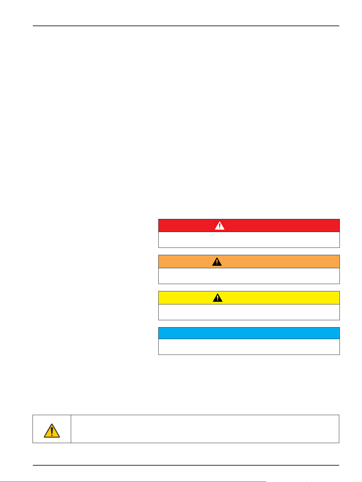
2.1.1 Use of hazard information
2.1.2 Precautionary labels
DANGER
Indicates a potentially or imminently hazardous situation which, if not
avoided, will result in death or serious injury.
WARNING
Indicates a potentially or imminently hazardous situation which, if not
avoided, could result in death or serious injury.
CAUTION
Indicates a potentially hazardous situation that may result in minor or
moderate injury.
Notice
Indicates a situation that, if not avoided, could result in damage to the
instrument. Information that requires special emphasis.
Note: Information that supplements points in the main text.
Read all labels and tags attached to the instrument. Personal injury
or damage to the instrument could occur if not observed.
This symbol, if noted on the instrument, references the instruction manual for operation
and/or safety information.
7
Page 8
General information
Electrical devices marked with this symbol may after August 12, 2005 no longer be disposed of in unsorted
domestic or industrial waste Europe-wide. In conformity with European local and national regulations (EU
Directive 2002/96/EC), European electrical equipment users must now return old or end-of life equipment to
the manufacturer for disposal This is free for the consumer.
Note: Obtain instructions on the correct disposal of all (marked and not marked) electrical products that were
supplied or manufactured by the manufacturer at the relevant sales office.
2.2 General sensor information
2.2.1 Property rights note
The SONATAX sc is intended for the measurement of sludge levels
in water. Use in other media without test of the materials (refer to
Section 1 Technical data on page 5) or consultation with the
manufacturer is regarded as explicitly not in accordance with
requirements.
Any use other than use in accordance with requirements defined in
the user manual leads to the loss of the warranty claims and can
lead to personal injury and property damage, for which the
manufacturer assumes no liability.
Parts of the device software are based on the work of the
Independent JPEG Group.
2.2.2 Usage areas
2.3 Device overview
The SONATAX sc can be used anywhere that the solid/liquid
separation layer must be monitored.
For example in the area of final sedimentation or in sludge
treatment (thickeners).
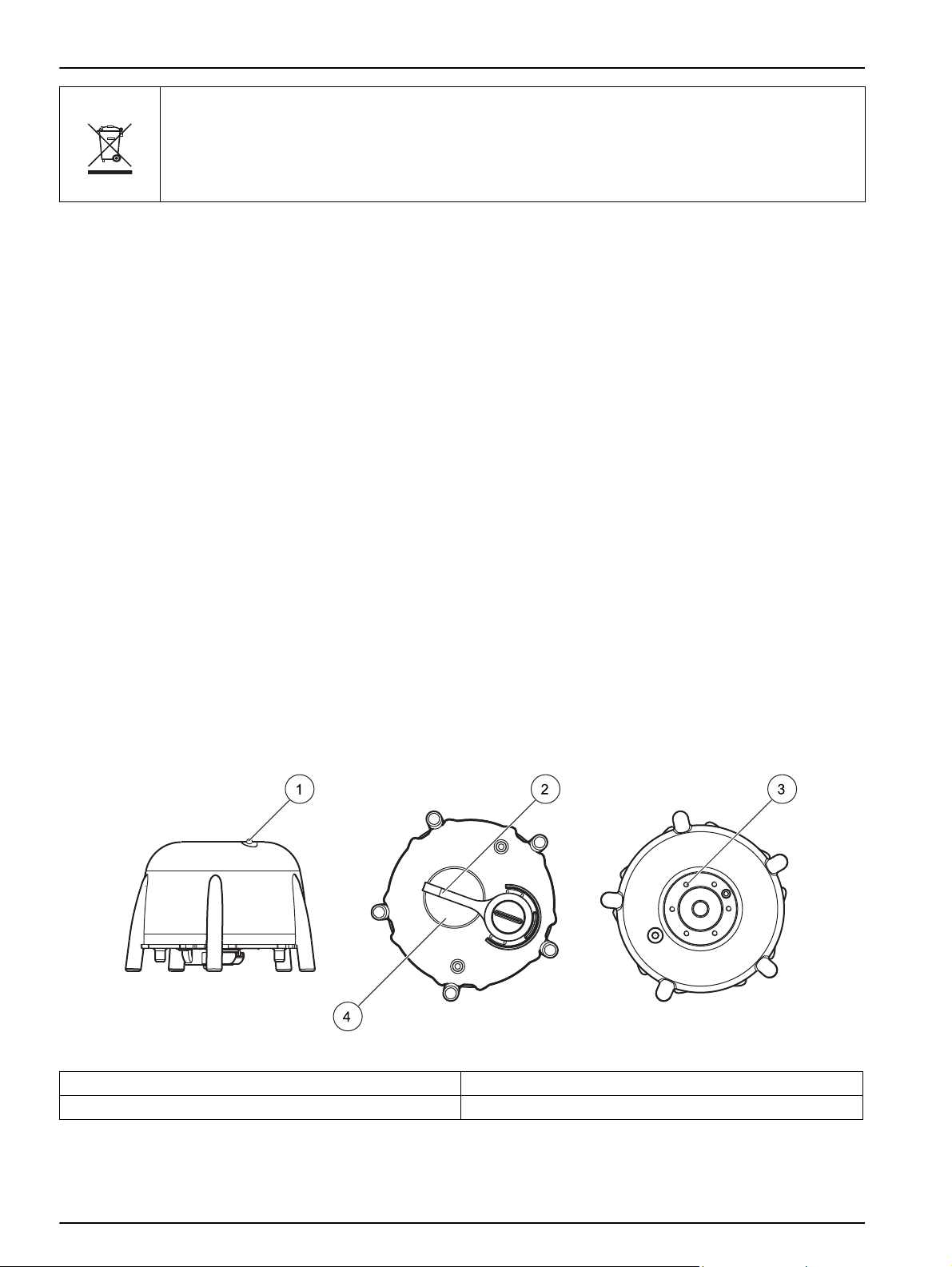
Figure 1 shows the device components of the SONATAX sc.
Figure 1 Device overview
1 Operating state LED (refer to Section 6.1) 3 Mount for the tank edge attachment
2 Wiper 4 Sensor head
8
Page 9
2.4 Functional principle
General information
In a tank where solid materials in water (or another fluid) can settle
to the bottom, there is a boundary between the settled solids and
the clear phase above. The distance from the water surface to the
bottom is the sludge level. The sludge height is the distance from
the tank floor.
More precisely, the sludge level (or the sludge height) indicates the
place in a tank where (viewed from the water surface) the solid
content first exceeds a defined limit. This limit value depends on the
application. It will, for example, be higher in a pre-thickener of a
wastewater treatment plant than in its final sedimentation, where
the overlying fluid should be clear water.
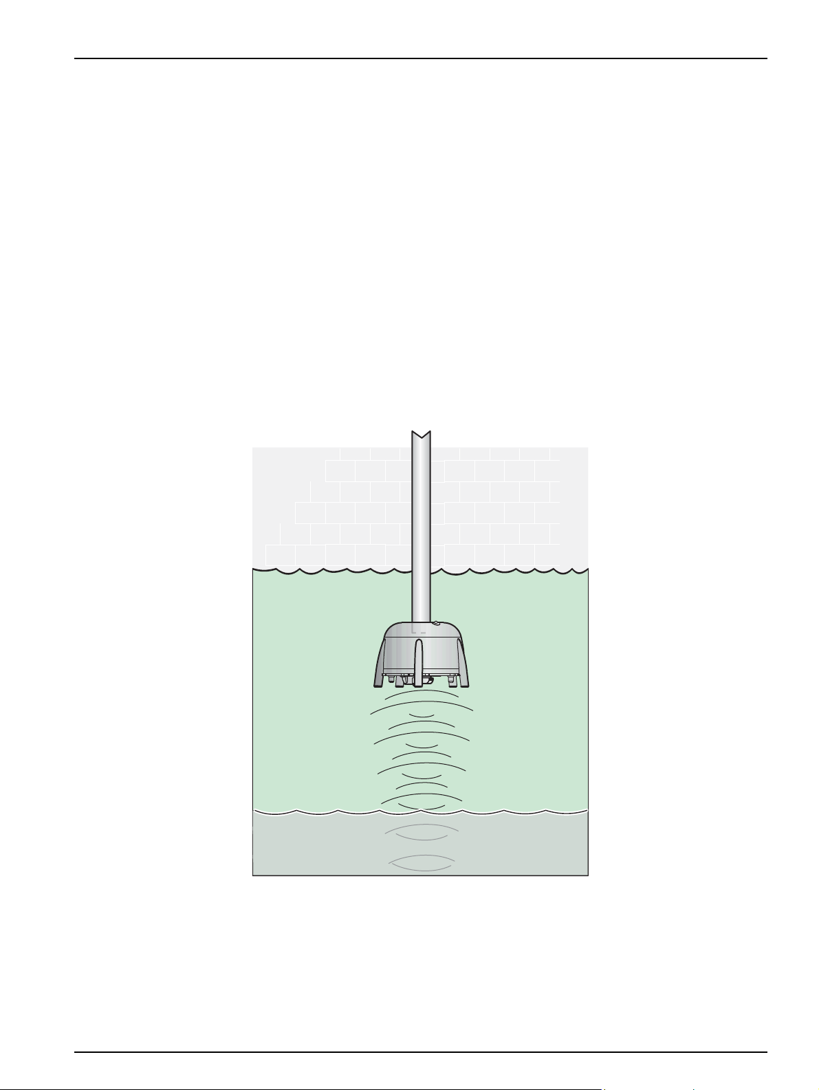
The SONATAX sc measures the sludge level via an echo signal
(refer to Figure 2) of an ultrasonic pulse. This echo signal is shown
in the probe menu SENSOR SETUP > TEST / MAINT > SIGNALS
in the echo list (refer to ECHO LIST on page 26). The depth and the
echo strength are specified at the ultrasonic transducer in digits
(1 digit approximately 1 µV).
Figure 2 Functional principle
Echos from layers that are further away are quieter (weaker) than
those which are closer. The SONATAX sc compensates for this
attenuation. The result is indicated on the SONATAX sc as a profile.
The data is found in the probe menu SENSOR SETUP > TEST /
MAINT > SIGNALS in the profile list (refer to PROFILE LIST on
9
Page 10
General information
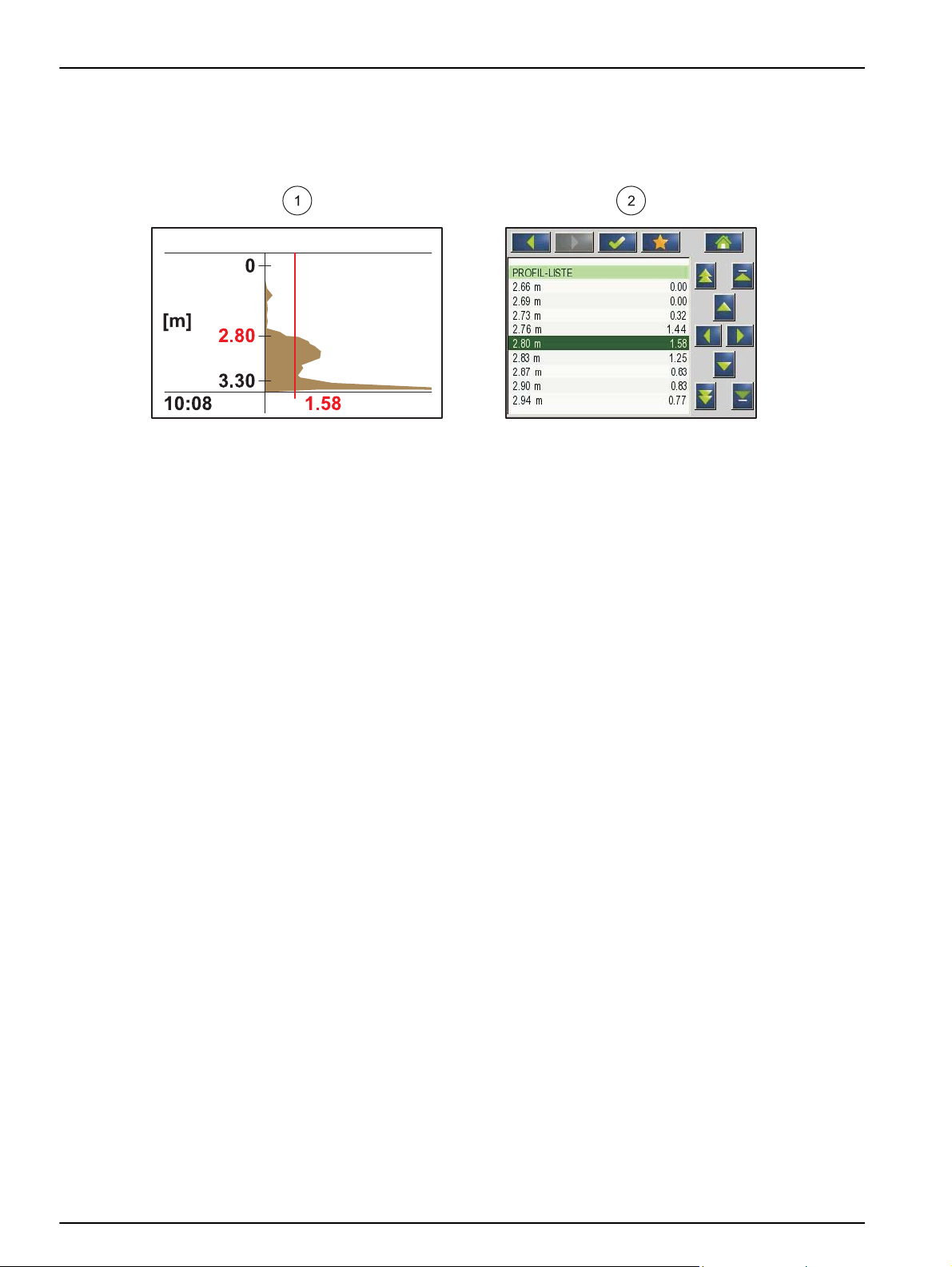
page 26) ((2) Figure 3). The graphic display (for example sc1000)
shows the profile in the measurement operation as a graphic ((1)
Figure 3).
Figure 3 Profile as graphic and list
The example shows a typical profile curve of a sludge level
measurement. The Y axis in this graphic reaches from the floor
(which can be set in the probe menu SENSOR SETUP >
CALIBRATE > TANK DEPTH on page 24) up to the water surface.
The profile strength is given on the X axis. The profile increases at
a sludge level. If the solid content below the sludge level remains
constant, the profile strength decreases again due to the absorption
of the ultrasound in the sludge. At the very bottom, the echo of the
floor is normally detected.
The vertical line represents the threshold. The sludge level is
detected by the SONATAX sc at the point at which the profile
exceeds this threshold for the first time viewed from above
(analogous to the abovementioned definition of the sludge level). In
the graphic, the detected sludge level is identified by a mark on the
Y axis.
The threshold is set automatically on the SONATAX sc (setting:
THRESHOLD AUTO = xy % in the probe menu SENSOR SETUP >
CALIBRATE > ADV.SETTINGS > THRESHOLD AUTO on
page 24). The automatic threshold function searches for the
maximum in the detected profile. Through an exact setting of the
tank depth, a faulty measurement due to the echo of the floor is
ruled out.
The background is that the echo signal of the floor in most tanks is
the strongest in the profile. With a correct setting of the tank depth,
the floor signal is not considered by the automatic threshold
function during the determination of the sludge level.
For more information on the correct determination of the tank
depth, refer to section Section 3.4.1 on page 13.
10
Page 11
Section 3 Installation
3.1 Unpack sensor
DANGER
The installation described in this section of the user manual should only
be performed by qualified and specialized personnel. The sensor is not
suitable for installation in hazardous areas.
The SONATAX sc can be used with an sc100, sc200 or with an
sc1000 controller. Installation instructions are found in the
handbook of the controller.
The SONATAX sc is supplied with the following components:
• Sensor
• User manual
• Wiper blades set (5 pieces)
If one of the parts is missing or damaged, please contact the
manufacturer or dealer.
3.1.1 Handling of the immersed probe
The immersed probe contains a sensitive ultrasound transducer.
Make sure that this is subjected to no hard mechanical impacts. Do
not install the probe hanging on the cable. Make sure before the
insertion of the probe into the medium that all functions run
undisrupted through a check of the system. Check the probe
carefully for external damage.
3.2 Connect sensor to an sc controller
3.2.1 Connect sensor with quick connection
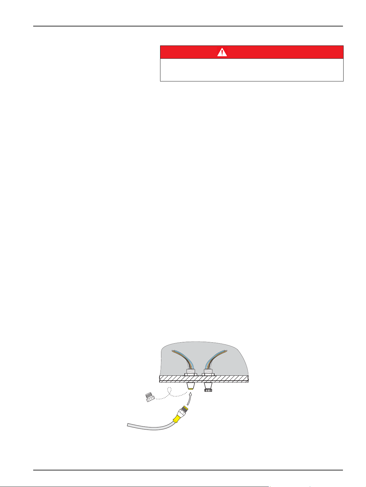
The sensor cable is very easy to connect to the controller using a
quick connection (Figure 4). Keep the protective cap of the
connection socket in case you remove the sensor later and must
seal the socket. For longer sensor cable lengths, optional extension
cables are available.
Figure 4 Connect sensor with quick connection
11
Page 12
Installation
1
2
3
4
5
6
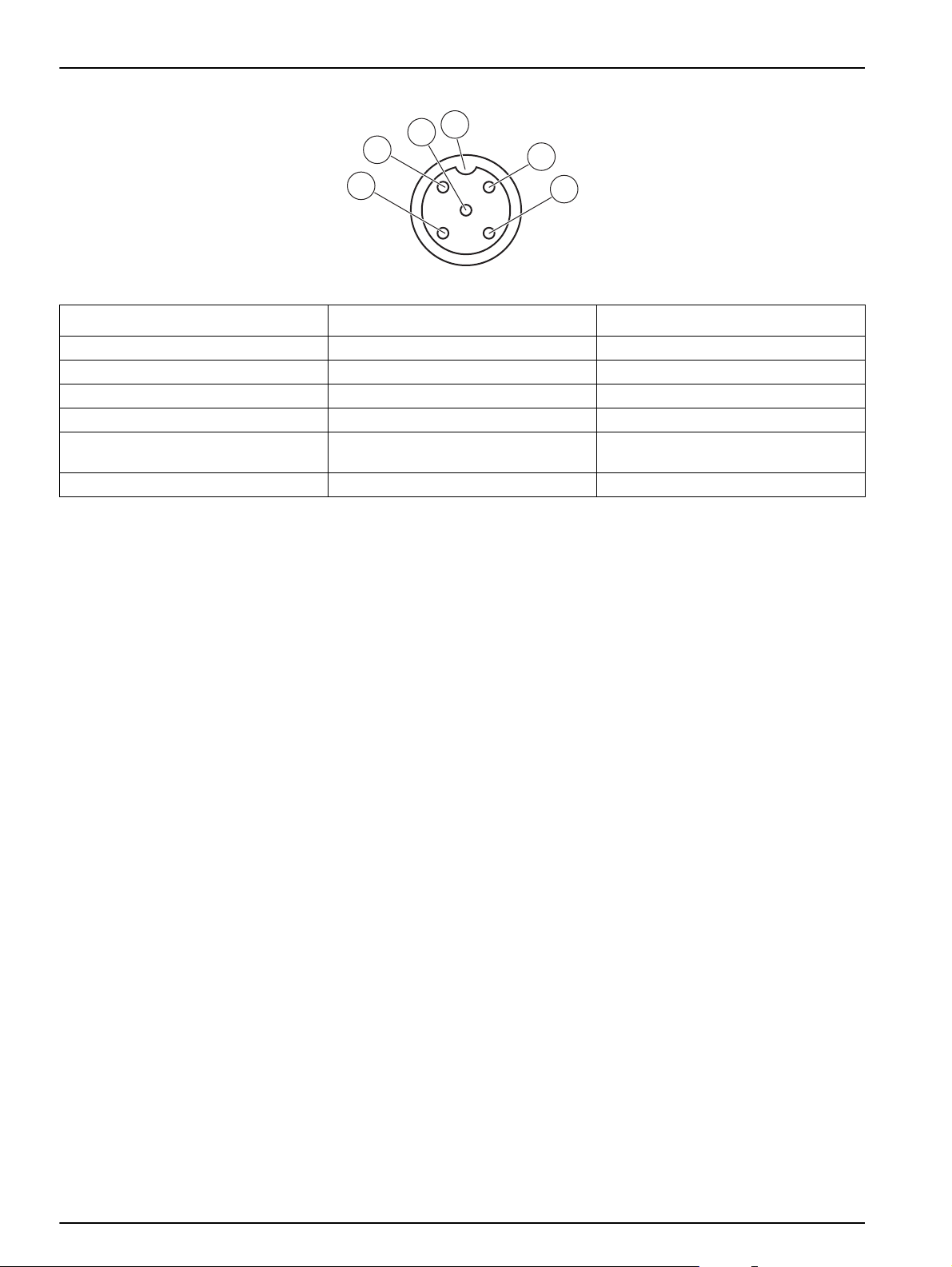
Figure 5 Pin assignment of the quick connection
Number Assignment Wire color
1 +12 V= Brown
2EarthBlack
3 Data (+) Blue
4 Data (–) White
5Shield
6 Insulator notch
Shield (gray wire for existing quick
connection)
3.3 Function test
Directly after the connection of the sensor to the controller, perform
a function check.
1. Connect the controller to the mains power.
2. If the controller does not recognize the new sensor, go to the
SCAN SENSORS menu (refer to the user manual of the
controller).
3. Confirm any prompt and wait until the new sensor is found.
If the new sensor is found, the controller switches to the
measurement operation.
A wipe process is triggered and the device switches to the
measurement operation. If no other messages appear, the sensor
is functional.
Note: Measurements in air lead to no measurement values. The error
message SENSOR MEASURE is shown. This does not show a
malfunction.
12
Page 13

3.4 Install sensor
Installation
The SONATAX sc is intended for installation with a tank edge
attachment. For more information, refer to the installation
instructions of the tank edge attachment.
Note: Do not begin with the installation of the tank edge attachment before
the installation location is determined (refer to Section 3.4.1).
Figure 6 SONATAX sc scale drawing
3.4.1 Select the measurement location and pre-set the device
In the determination of the sludge level over the duration of an
ultrasonic echo, the entire space between the probe on the water
surface and the tank bottom is required for the measurement. As
solid bodies in this area disrupt the measurements, special
attention is required in the selection of the measurement location.
In the following, it is explained how the suitability of a possible
measurement location can be tested. The tank depth should be
known here.
A suitable measurement location must be found depending on tank
type. The graphics that follow show typical examples for a round
tank and a rectangular tank. The point (1) in Figure 7 and Figure 8
is a suitable measurement location.
13
Page 14

Installation
Figure 7 Round tank graphic
Figure 8 Rectangular tank graphic
At a suitable measurement location, there should be:
• Sufficient sludge present for the measurement, and
14
• A calm, clear phase above the sludge level
In the examples shown, area (A) shows only very little or no sludge,
while in the area (C) above the sludge layer, sludge clouds may
disrupt the measurement. The measurement points (A) and (C) are
Page 15

not suitable for the installation. Suitable measurement points can be
found in between.
Note: Installation note: For round tanks with a rotating scraper bridge,
install the probe in the direction of rotation on the back of the bridge
(Figure 7).
3.4.1.1 Determine the distance to the tank edge
If the SONATAX sc is installed on the tank edge (i.e. not on a
scraper bridge), make sure there is sufficient distance from the
SONATAX sc to the tank edge.
This distance is dependent on the depth of the tank.
Use this formula to find a guideline value for this distance:
0.20 m + (0.05 x tank depth in meters) = distance to tank edge
This value can vary depending on composition of the tank. How a
possible installation location can be checked for its suitability is
described in Section 3.4.1.2 Determine measurement location.
3.4.1.2 Determine measurement location
1. Connect the probe to the sc controller and carefully immerse
the probe in the water (approximately
probe cable at the selected measurement location.
Installation
20 cm (7.9 in.)) on the
2. Select the probe menu SENSOR SETUP > CALIBRATE and do
a measurement in the REFLEXLIST menu item.
After a few seconds, the reflex list is shown (refer to REFLEXLIST
on page 24). This list usually contains the tank floor as the
strongest signal.
If strong reflections between the water surface and the tank floor
are present (for example due to pipes, plates etc.), another
measurement location must be selected. Sometimes it is sufficient
to move the probe by a few centimeters.
In the example (Table 1), there are two disruptive reflexes at a
depth of 0.87 m and 2.15 m, and the tank floor is at a depth of
3.30 m.
Table 1 Reflex list
Meters Intensity
0.87 25 %
2.15 2 %
3.30 100 %
At an ideal measurement location, no disruptive reflections should
occur above the floor in the reflex list after multiple measurements
(Table 2).
Table 2 Reflex list
Meters Intensity
3.30 100 %
15
Page 16

Installation
If no measurement location without disruptive reflexes can be
found, select the probe menu SENSOR SETUP > CALIBRATE and
trigger a measurement in the PROFILE LIST menu item.
• If there are increased values at the depth of the disruptive
reflexes in the PROFILE LIST which influence the
measurement value, another measurement location must be
selected. Sometimes it is sufficient to move the probe by a few
centimeters (refer to
Figure 9, right).
• If the reflections do not disrupt the measurement value, this can
be a suitable measurement location (refer to
Figure 9, left).
Figure 9 Determine measurement location
3. Then assemble the tank edge attachment there and install the
probe.
Note: The probe should be installed approximately 20 cm (7.9 in.) deep
at the installation location (somewhat more than the entire probe head) to
make sure that it remains immersed during the entire measurement
operation.
4. In the CALIBRATE probe menu, enter the actual plunger depth
(Item A,
Figure 10) in the PLUNGERDEPTH menu item.
5. Trigger after approximately 2 minutes another measurement of
the reflex list (to adjust the temperature sensor to the water
temperature) (also refer to
6. In the CALIBRATE probe menu, enter the recorded value of the
tank depth (Item C,
Figure 10) in the TANK DEPTH menu item.
Important note: The shown value of the tank depth is calculated
from information shown:
Tank depth C = plunger depth A + measured distance to floor B
This calculation is performed internally and leads to incorrect
results if the plunger depth is entered incorrectly.
REFLEXLIST on page 24).
16
Page 17

Installation
Figure 10 Plunger depth–tank depth
Note: Should the reflex list not contain the tank depth (possible when there
is a lot of sludge above the floor), the tank depth must be determined in
another way (e.g. measuring).
Important note: The value entered in the TANK DEPTH menu item
must in no case be larger than the actual tank depth. This could
lead to incorrect measurement values.
In the determination of a suitable measurement location, the
optionally available SLUDGE DOCTOR diagnostic software can be
helpful (refer to 7.2 Accessories on page 31). The software enables
the representation and saving of all graphic profiles of the
SONATAX sc in a defined time interval (5 minutes–2 hours).
17
Page 18

Installation
3.4.2 Installation of the sensor
The software also shows and saves all important measurement and
configuration parameters, such as the reflex list, measurement
values, limit values and all advanced settings, such as response
time, frequency, amplitude, angle and temperature.
Take further information from the SLUDGE DOCT OR user manual
DOC013.98.90411.
Note: Take further information on the installation from the installation
instructions.
3.5 Advanced settings
18
Figure 11 Installation of the sensor
In the SENSOR SETUP > CALIBRATE > ADV. SETTINGS menu,
special probe parameters can be found.
The default settings of these parameters are selected so that no
correction is required in most applications. In exceptional cases,
these parameters must be adapted depending on the application.
The examples that follow show typical sludge profiles.
Page 19

Installation
Example 1: Pre-thickener with clear separation layer, but
sporadically empty.
The image shows a thickener with a clear profile. The signals above
the sludge level caused by turbid water do not disrupt the
measurement.
The same thickener is empty in this image. The threshold now
justs itself automatically to the signals of the turbid water. The
ad
recorded measurement value at 0.63 m is incorrect.
Recommended measure:
Increase the adjustment of the ADV. SETTINGS > LL THRESH.
AUTO setting from 0.3 to 1.0.
Note: LL THRESH. AUTO gives the smallest possible value that the
threshold can accept.
The image shows the empty thickener after the adjustment. The
result 3.18 m is correct.
Example 2: Application with c
signal.
Very low to absolutely no interference signals through turbid water
above the separation layer. Strength of the echo 0.61 is above the
LL THRESH. AUTO (pre-setting 0.3) and leads to correct
measurement value 2.28 m.
lear separation layer, but weak
19
Page 20

Installation
Very low to absolutely no interference signals through turbid water
above the separation layer. Strength of the maximum echo <0.3.
Instead of the correct measurement value, only the tank floor is
found.
Increase the adjustment of the ADV. SETTINGS > LL THRESH.
O setting from 0.3 to 0.1. The threshold 0.16 finds the correct
AUT
measurement value 2.25 m.
Example 3: Thickene
concentration up to just under the water surface; echo is absorbed
in the uppermost sludge layer:
In this application, the floor signal is no longer detected due to the
high absorption of the ultrasonic signal. The shown measurement
value 0.73 is correct. No adjustment of the ADV. SETTINGS
necessary.
If the sludge increases so far that the sludge level is above the
easurement range (the measurement range begins from 0.2 m
m
beneath the sensor), it can occur that no sludge level is detected
(SENSOR MEASURE error message). In this case, the application
must be checked.
r or other application with very high sludge
20
Page 21

Installation
Example 4: Application with large tank depth and clear separation
layer, but high absorption of the ultrasound by turbid materials
above the separation layer.
Absorption is so high that no sludge level is detected at a plunger
depth of 0.2 m and LL THRESH. AUTO 0.1 (SENSOR MEASURE
error message).
After adjustment of the plunger depth SENSOR SETUP >
CALIBRA
precisely determined at 3.30. The strength of the echo 1.41 shows
that there is a clear separation layer.
Note: After adjustment of the plunger depth, the setting of the tank floor
must be checked (SENSOR SETUP > CALIBRATE > TANK DEPTH)
TE > PLUNGERDEPTH to 3 m, the sludge level can be
Example 5: Application with clear separation layer, but interference
signal above the separation layer (for example skimmer).
Ideal profile, correct measurement value.
The same measurement point with sporadic interference of the
o in a 0.67 m tank depth. The measurement value is incorrect.
ech
21
Page 22

Installation
Fade out this disruption in SENSOR SETUP > CALIBRATE > ADV.
SETTINGS > FADE-OUT in the range of 0.5–0.8 m. The sensor
now ignores all signals in this range and finds the correct
measurement value at 2.13 m.
Example 6: Application
cloud above the separation layer.
In this application, the separation layer should be measured, the
sludge cloud should be ignored (for example pre-thickener).
No change of the default setting. The automatic threshold detects
the separation layer; the echo of the sludge cloud is lower than the
echo of the sludge cloud.
The image shows the same profile as before, but with another
reshold and measurement value.
th
In this application, the sludge cloud should be measured as an
early warning system (for example sludge drift in the final
clarification tank).
Change of the automatic threshold SENSOR SETUP >
CALIBRATE > ADV. SETTINGS > THRESHOLD AUTO to 25 %.
The automatic threshold detects the sludge cloud.
with clear separation layer and a sludge
22
The optionally available SLUDGE DOCTOR diagnostic software
can be helpful for the setting of the special probe parameters (refer
to 7.2 Accessories on page 31). The software enables the
representation and saving of all graphic profiles of the SONATAX sc
in a defined time interval (5 minutes–2 hours).
The software also shows and saves all important measurement and
configuration parameters, such as the reflex list, measurement
values, limit values and all advanced settings, such as response
time, frequency, amplitude, angle and temperature.
Take further information from the SLUDGE DOCT OR user manual
DOC013.98.90411.
Page 23

Section 4 Operation
4.1 Use of the sc controller
4.2 Sensor data logging
4.3 Sensor setup
Before using the sensor with an sc controller, make yourself familiar
with the operating method of the controller. Learn to navigate
through the menu and to use the menu functions. Further
information is found in the user manual of the controller.
The sc controller provides one data log and one event log for each
sensor. The data log stores the measurement data at selectable
intervals. The event log stores a large number of events that occur
on the devices, such as configuration changes, alarms and
warnings etc. The data log and the event log can be read out in
CSV format. Refer to the controller user manual for more
information about the log download.
During initial sensor setup, select the parameter that corresponds
to the applicable instrument.
4.3.1 Change of the sensor name
When a sensor is installed for the first time, the serial number is
shown as the measurement location (or sensor name). The
measurement location can be changed as follows:
1. From the main menu, select SENSOR SETUP and confirm the
selection.
2. If more than one sensor is connected, mark the required sensor
and confirm the selection.
3. Select CONFIGURE and confirm the selection.
4. Select EDITED NAME and edit the name. Return to the Sensor
Setup menu with confirm or cancel.
4.4 SENSOR STATUS menu
Select the SONATAX sc (if several sensors are connected)
SONATAX sc
ERRORS Lists error messages; refer to 6.2 Error messages on page 29
WARNINGS Lists warnings; refer to 6.3 Warnings on page 30
4.5 SENSOR SETUP menu
Select the SONATAX sc (if several sensors are connected)
WIPE
CALIBRATE
Plunger depth of the probe underside (refer to 3.4.1.2 Determine measurement
PLUNGERDEPTH
location on page 15).
Configurable: 0.1 m to 3 m (0.3 ft to 9.8 ft)
23
Page 24

Operation
4.5 SENSOR SETUP menu (Continued)
Select the SONATAX sc (if several sensors are connected)
Shows the reflex list. A new measurement can be triggered.
A list is shown of all detected solid bodies that have clearly reflected the ultrasonic
impulse. The measurement depth is shown in m or ft and the strength of the
REFLEXLIST
TANK DEPTH
PROFILE LIST
ADV. SETTINGS
FACTOR
THRESHOLD AUTO
LL THRESH. AUTO
FADE-OUT
BEGIN
END
SET DEFAULTS
reflected signal in %, relative to the strongest signal in the list. This list mostly
contains the tank floor. If strong reflections between the water surface and the tank
floor are present (for example due to pipes, plates etc.), it should be checked
whether another installation location offers better conditions.
Entry of the floor depth (refer to 3.4.1.2 Determine measurement location on
page 15).
Configurable: 1.00 m to 12 m (3.3 ft to 39.4 ft)
A profile is calculated from the ultrasound echo and shown for the corresponding
depths respectively as profile strength. The profile is similar in its curve with the TS
profile of the tank. At an average solid content, the values are in the order of 1. A
new measurement can be triggered (refer to Figure 3 on page 10).
Correction factor for the speed of sound.
Configurable: 0.3 to 3.0, default setting 1.0
A change of the default factor is only required if the local speed of sound in the fluid
deviates from the speed of sound in water:
Factor (fluid) = speed of sound (fluid) / speed of sound (water)
Note: For applications in water, the factor should remain at 1.0.
With the automatic threshold function, the system constantly adapts the
environmental conditions and automatically changes the sensitivity in order to
guarantee maximum accuracy.
Recommendation: 75%
Configurable: 1-95%
LL THRESH. AUTO gives the smallest possible value that the threshold can accept.
Configurable: 0.1 to 1.0, recommendation 0.3
If fixed installations or other influences interfere at certain tank depths, then this
range can be faded out —·it is then completely ignored.
Configurable: ON, OFF
Upper limit of the range that should be faded out.
Only active when FADE-OUT = ON.
Lower limit of the range that should be faded out.
Only active when FADE-OUT = ON.
Reset to factory configuration for all probe-specific parameters. This occurs only
after a security prompt.
24
Page 25

4.5 SENSOR SETUP menu (Continued)
Select the SONATAX sc (if several sensors are connected)
KONFIGURIEREN (CONFIGURE)
Operation
EDIT NAME
PAR AMETER
MEAS UNITS
CLEAN. INTERVAL
RESPONSE TIME
LOGGER INTERVAL
SET DEFAULTS
TEST / MAINT
PROBE INFO
SENSOR NAME Display of the device name.
EDIT NAME
SERIAL NUMBER. Device number
MODEL NUMBER Item no. of the sensor.
HARDWARE-VERS Production status of main circuit board
SOFTWARE-VERS Sensor software version
COUNTER
WIPER COUNTER
TOTAL TIME Operating hours counter
MOTOR Forward counter for wiping processes.
TEST / MAINT Date of the last performed maintenance.
REPLACE PROFILE
Freely editable (up to 16 characters)
Factory setting: device number
The measurement result can be shown as the sludge level (as the distance of the
sludge from the water surface) or as the sludge height (as the distance from the tank
floor). To calculate the sludge height, the tank depth specified in the TANK DEPTH
menu item is used.
(Sludge height = tank depth – sludge level)
Configurable: sludge level, sludge height
Dimension of the measurement result.
Configurable: meters, feet
Wipe interval,
Recommendation: 15 minutes
Configurable: 1 minute to 1 hour
Damping of the measurement value. In the case of high measurement value
fluctuations, a high damping of for example 300 seconds is recommended.
Configurable: 10 to 1800 seconds
The interval for the internal data log.
Configurable: 1, 2, 3, 4, 5, 6, 10, 15, 30 minutes
Reset to factory configuration for all menu items listed above. This occurs only after
a security prompt.
Display of the freely selectable measurement location
(factory setting: device number).
Backward counter for wiping processes of the wiper profile.
After expiration of the counter, a warning message is shown. In the case of a wiper
change, the counter should be reset again.
For the wiper profile change, the wiper arm moves to a central position. In this
position, the wiper arm can then be removed and installed without problems.
25
Page 26

Operation
4.5 SENSOR SETUP menu (Continued)
Select the SONATAX sc (if several sensors are connected)
TEST / MAINT
SIGNALS
MOIST Indicator as to whether water is in the probe.
TEMPERATURE Temperature of the surrounding water in °C or F°.
SENSOR ANGLE Deviation of the probe axis from the perpendicular in degrees.
The received echo signal in digits (units of the AD converter) is shown at the
ECHO LIST
PROFILE LIST
REFLEXLIST
FREQUENCY The resonance frequency of the ultrasound transducer is shown.
AMPL DIAG The resonance voltage of the ultrasound transducer is shown.
THRESHOLD
SHOW AMPL.
corresponding measurement depths in a list. The first element at 0 meters shows the
strength of the transmission pulse.
A new measurement can be started.
A profile is calculated from the ultrasound echo and shown for the corresponding
depths respectively as profile strength. The profile is similar in its curve with the TS
profile of the tank. At an average solid content, the values are in the order of 1.
A new measurement can be started. (See Figure 3 on page 10)
Shows the reflex list. A new measurement can be triggered. Refer to REFLEXLIST
on page 24
To determine the sludge level, a profile is first calculated from the ultrasonic echo.
This roughly returns the solid content depending on the tank depth. The sludge level
is assigned to the tank depth where the profile exceeds the threshold for the first
time.
On activation, the resonance profile of the ultrasound transducer is shown instead of
the sludge profile (PROFILE LIST) as a graphic in the measurement window (only
valid with sc1000). The resonance profile can be switched ON and OFF.
After switch-off, the sludge profile (PROFILE LIST) is shown on the measurement
window again.
26
Page 27

Section 5 Maintenance
Multiple hazards. Only qualified personnel must conduct the tasks
described in this section of the document.
No components that can be serviced by the user are in the inside of
the probe. Opening of the probe by the user leads to the loss of the
manufacturer guarantee and may cause malfunctions.
The cleanliness of the ultrasound transducer is crucial for the
accuracy of the measurement results.
The installed wiper is able to remove all impurities under normal
circumstances and if the selection of the wiper interval is not too
large (30 minutes).
If the regular check of the probe head and of the wiper (monthly)
indicates dirt, wear of the wiper rubber or a defect, then either the
probe head must be cleaned, or the wiper profile and/or the
defective part must be exchanged.
5.1 Maintenance tasks
DANGER
Take the maintenance intervals from Table 3.
Table 3 Maintenance schedule
Time interval Action
Monthly Visual inspection, if necessary, clean
Annually, at the latest after 20,000 wipe cycles Change wiper rubber
5.2 Wiper change
CAUTION
Obey the locally applicable accident prevention regulations. Wear
protective gloves where necessary during the change of the wiper
rubber.
1. Go to SENSOR SETUP > TEST / MAINT >
REPLACE
The wiper arm (refer to item 3 in Figure 12) moves for the wiper
change into a central position.
2. Remove the guide screw (refer to item 2 in Figure 12) and take
off the wiper arm.
PROFILE.
3. Pull the wiper profile (refer to item 1 in Figure 12) forward out of
the wiper arm.
4. Slide a new wiper profile with the bevel at the front into the
guide.
27
Page 28

Maintenance
5. Install the wiper arm again and tighten the guide screw again
by hand.
Note: Only tighten the screw hand-tight until the safety lugs have audibly
engaged 2–3 times.
6. Select OK and the wiper arm automatically moves back to the
initial position.
Figure 12 Wiper unit
1 Wiper profile 3 Wiper arm
2 Guide screw
5.3 Cleaning tasks
Use water and a suitable brush to remove heavy contamination on
the probe or on the strut as necessary.
Clean the ultrasound transducer carefully with water and a lint-free
cloth.
28
Page 29

Section 6 Troubleshooting
6.1 Operating state LED
The sensor is equipped on the top side with an LED that provides
information on the operating state.
Figure 13 Operating state LED
1 Operating state LED
Table 4 Sensor status
Green LED No errors or warnings
Green/red flashing LED
Red LED Error
LED off No device function
Probe in operation, probe position deviates strongly from the perpendicular, the
measurement value is retained, there is no error
6.2 Error messages
In the case of an error, an error message is shown on the controller.
Find error messages and notes on the resolution of the errors in
Table 5.
Table 5 Error messages
Error message Reason Resolution
The PROFILE LIST and graphic on the sc1000
is less than the programmed value for
SENSOR MEASURE
POS. UNKNOWN
AMPL DIAG Internal error Call service
MOIST Moisture value \> 10 Call service
SENSOR ANGLE
SYSTEM ERROR Faulty RAM Call service
LL THRESH.AUTO. over the entire tank depth,
or the ultrasound transducer is contaminated or
not immersed.
The wiper position is not detected. The wiper is
in the central position (after a wiper change).
Defective light barrier plate Call service
Application with particles that block the wiper.
The probe is more than 20° from perpendicular
and for longer than 180 seconds.
Incorrectly calibrated position sensor Call service
Check device data, also the plunger depth,
floor depth and advanced settings, check
installation and remove contamination.
Start a wiping process
Cleaning of the ultrasound transducer and of
the wiper system.
Check installation
29
Page 30

Troubleshooting
6.3 Warnings
In the case of a warning, a warning message is shown on the
controller. Find warnings and notes on the resolution of the warning
in Table 6.
Table 6 Warnings
Warning message Reason Resolution
REPLACE PROFILE The counter for the wiper profile has expired Change wiper profile
6.4 SLUDGE DOCTOR, (diagnostic software for SONATAX sc)
SLUDGE DOCTOR is an optionally available diagnostic software
for the SONATAX sc probe in connection with the controllers sc100,
sc200 or sc1000. The software enables the representation and
saving of all graphic profiles of the SONATAX sc in a defined time
interval (5 minutes–2 hours).
The software also shows and saves all important measurement and
configuration parameters, such as the reflex list, measurement
values, limit values and all advanced settings, such as response
time, frequency, amplitude, angle and temperature.
Take further information from the SLUDGE DOCT OR user manual
DOC013.98.90411.
30
Page 31

Section 7 Replacement parts and accessories
7.1 Replacement parts
Description Number Order number
SONATAX sc 1 LXV431.99.00001
1 set of replacement wiper blades out of silicone
for SONATAX/SONATAX sc probes (5 pieces)
Wiper arm 1 LZY344
Guide screw
(for stopping the wiper arm)
User manual (xx=language code) 1 DOC023.xx.00117
7.2 Accessories
Description Order number
Pivot attachment set, 0.35 m (1.15 ft) LZX414.00.72000
Pivot attachment set, 1 m (3.3 ft) LZX414.00.71000
Rail assembly attachment set LZX414.00.73000
Tank edge attachment set LZX414.00.70000
Scraper bridge attachment set LZX414.00.74000
SONATAX sc chain stay LZX914.99.11300
SLUDGE DOCTOR, diagnostic software without interface cable LZY801.99.00000
SLUDGE DOCTOR, diagnostic software with sc200 interface cable LZY801.99.00010
SLUDGE DOCTOR, diagnostic software with sc1000 interface cable LZY801.99.00020
1LZX328
1LZY345
31
Page 32

Replacement parts and accessories
32
Page 33

Section 8 Warranty and liability
The manufacturer warrants that the supplied product is free of
material and manufacturing defects, and undertakes to repair or to
replace any defective parts without charge.
The warranty period is 24 months. If a maintenance contract is
taken out within 6 months of purchase, the warranty period is
extended to 60 months.
With the exclusion of further claims, the supplier is liable for
defects, including the lack of assured properties, as follows: all
parts that, within the warranty period calculated from the day of the
transfer of risk, can be demonstrated to have become unusable or
that can only be used with significant limitations owing to
circumstances prior to transfer of risk, in particular due to incorrect
design, substandard materials or inadequate finish, shall be
repaired or replaced at the supplier's discretion. The identification
of such defects must be reported to the supplier in writing as soon
as possible, but no later than 7 days after the discovery of the fault.
If the customer omits this notification, the product is considered
approved despite the defect. Further liability for indirect or direct
damages is not accepted.
If device-specific maintenance- or inspection work prescribed by
the supplier is to be performed within the guarantee period by the
customer (maintenance) or by the supplier (inspection) and these
requirements are not met, claims for damages that result from
non-observance of these requirements are void.
Further claims, in particular for consequential damages, cannot be
made valid.
Wear and damage caused by improper handling, incorrect
installation or non-designated use are excluded from this clause.
The process instruments of the manufacturer are of proven
reliability in many applications and are therefore often used in
automatic control loops to enable the most economical and efficient
operation of the relevant process.
To avoid or limit consequential damage, it is therefore
recommended that the control loop be designed such that an
instrument malfunction results in an automatic changeover to the
backup control system. This guarantees the safest operating
condition both for the environment and the process.
33
Page 34

Warranty and liability
34
Page 35

Section 9 Contact
HACH Company
World Headquarters
P.O. Box 389
Loveland, Colorado
80539-0389 U.S.A.
Tel (800) 227-HACH
(800) -227-4224
(U.S.A. only)
Fax (970) 669-2932
orders@hach.com
www.hach.com
HACH LANGE GMBH
Willstätterstraße 11
D-40549 Düsseldorf
Tel. +49 (0)2 11 52 88-320
Fax +49 (0)2 11 52 88-210
info@hach-lange.de
www.hach-lange.de
HACH LANGE GMBH
Rorschacherstrasse 30a
CH-9424 Rheineck
Tel. +41 (0)848 55 66 99
Fax +41 (0)71 886 91 66
info@hach-lange.ch
www.hach-lange.ch
Repair Service in the
United States:
HACH Company
Ames Service
100 Dayton Avenue
Ames, Iowa 50010
Tel (800) 227-4224
(U.S.A. only)
Fax (515) 232-3835
HACH LANGE LTD
Pacific Way
Salford
GB-Manchester, M50 1DL
Tel. +44 (0)161 872 14 87
Fax +44 (0)161 848 73 24
info@hach-lange.co.uk
www.hach-lange.co.uk
HACH LANGE FRANCE
S.A.S.
8, mail Barthélémy Thimonnier
Lognes
F-77437 Marne-La-Vallée
cedex 2
Tél. +33 (0) 820 20 14 14
Fax +33 (0)1 69 67 34 99
info@hach-lange.fr
www.hach-lange.fr
Repair Service in Canada:
Hach Sales & Service
Canada Ltd.
1313 Border Street, Unit 34
Winnipeg, Manitoba
R3H 0X4
Tel (800) 665-7635
(Canada only)
Tel (204) 632-5598
Fax (204) 694-5134
canada@hach.com
HACH LANGE LTD
Unit 1, Chestnut Road
Western Industrial Estate
IRL-Dublin 12
Tel. +353(0)1 460 2522
Fax +353(0)1 450 9337
info@hach-lange.ie
www.hach-lange.ie
HACH LANGE NV/SA
Motstraat 54
B-2800 Mechelen
Tel. +32 (0)15 42 35 00
Fax +32 (0)15 41 61 20
info@hach-lange.be
www.hach-lange.be
Repair Service in
Latin America, the
Caribbean, the Far East,
Indian Subcontinent, Africa,
Europe, or the Middle East:
Hach Company World
Headquarters,
P.O. Box 389
Loveland, Colorado,
80539-0389 U.S.A.
Tel +001 (970) 669-3050
Fax +001 (970) 669-2932
intl@hach.com
HACH LANGE GMBH
Hütteldorfer Str. 299/Top 6
A-1140 Wien
Tel. +43 (0)1 912 16 92
Fax +43 (0)1 912 16 92-99
info@hach-lange.at
www.hach-lange.at
DR. LANGE NEDERLAND
B.V.
Laan van Westroijen 2a
NL-4003 AZ Tiel
Tel. +31(0)344 63 11 30
Fax +31(0)344 63 11 50
info@hach-lange.nl
www.hach-lange.nl
HACH LANGE APS
Åkandevej 21
DK-2700 Brønshøj
Tel. +45 36 77 29 11
Fax +45 36 77 49 11
info@hach-lange.dk
www.hach-lange.dk
HACH LANGE LDA
Av. do Forte nº8
Fracção M
P-2790-072 Carnaxide
Tel. +351 214 253 420
Fax +351 214 253 429
info@hach-lange.pt
www.hach-lange.pt
HACH LANGE KFT.
Vöröskereszt utca. 8-10.
H-1222 Budapest XXII. ker.
Tel. +36 1 225 7783
Fax +36 1 225 7784
info@hach-lange.hu
www.hach-lange.hu
HACH LANGE AB
Vinthundsvägen 159A
SE-128 62 Sköndal
Tel. +46 (0)8 7 98 05 00
Fax +46 (0)8 7 98 05 30
info@hach-lange.se
www.hach-lange.se
HACH LANGE SP. ZO.O.
ul. Krakowska 119
PL-50-428 Wrocław
Tel. +48 801 022 442
Zamówienia: +48 717 177 707
Doradztwo: +48 717 177 777
Fax +48 717 177 778
info@hach-lange.pl
www.hach-lange.pl
HACH LANGE S.R.L.
Str. Căminului nr. 3,
et. 1, ap. 1, Sector 2
RO-021741 Bucureşti
Tel. +40 (0) 21 205 30 03
Fax +40 (0) 21 205 30 17
info@hach-lange.ro
www.hach-lange.ro
HACH LANGE S.R.L.
Via Rossini, 1/A
I-20020 Lainate (MI)
Tel. +39 02 93 575 400
Fax +39 02 93 575 401
info@hach-lange.it
www.hach-lange.it
HACH LANGE S.R.O.
Zastrčená 1278/8
CZ-141 00 Praha 4 - Chodov
Tel. +420 272 12 45 45
Fax +420 272 12 45 46
info@hach-lange.cz
www.hach-lange.cz
HACH LANGE
8, Kr. Sarafov str.
BG-1164 Sofia
Tel. +359 (0)2 963 44 54
Fax +359 (0)2 866 15 26
info@hach-lange.bg
www.hach-lange.bg
HACH LANGE S.L.U.
Edificio Seminario
C/Larrauri, 1C- 2ª Pl.
E-48160 Derio/Vizcaya
Tel. +34 94 657 33 88
Fax +34 94 657 33 97
info@hach-lange.es
www.hach-lange.es
HACH LANGE S.R.O.
Roľnícka 21
SK-831 07 Bratislava –
Vaj nory
Tel. +421 (0)2 4820 9091
Fax +421 (0)2 4820 9093
info@hach-lange.sk
www.hach-lange.sk
HACH LANGE SU
ANALİZ SİSTEMLERİ
LTD.ŞTİ.
Ilkbahar mah. Galip Erdem
Cad. 616 Sok. No:9
TR-Oran-Çankaya/ANKARA
Tel. +90312 490 83 00
Fax +90312 491 99 03
bilgi@hach-lange.com.tr
www.hach-lange.com.tr
35
Page 36

Contact
HACH LANGE D.O.O.
Fajfarjeva 15
SI-1230 Domžale
Tel. +386 (0)59 051 000
Fax +386 (0)59 051 010
info@hach-lange.si
www.hach-lange.si
HACH LANGE OOO
Finlyandsky prospekt, 4A
Business Zentrum “Petrovsky
fort”, R.803
RU-194044, Sankt-Petersburg
Tel. +7 (812) 458 56 00
Fax. +7 (812) 458 56 00
info.russia@hach-lange.com
www.hach-lange.com
ΗΑCH LANGE E.Π.Ε.
Αυλίδος 27
GR-115 27 Αθήνα
Τηλ . +30 210 7777038
Fax +30 210 7777976
info@hach-lange.gr
www.hach-lange.gr
HACH LANGE D.O.O.
Ivana Severa bb
HR-42 000 Varaždin
Tel. +385 (0) 42 305 086
Fax +385 (0) 42 305 087
info@hach-lange.hr
www.hach-lange.hr
HACH LANGE MAROC
SARLAU
Villa 14 – Rue 2 Casa
Plaisance
Quartier Racine Extension
MA-Casablanca 20000
Tél. +212 (0)522 97 95 75
Fax +212 (0)522 36 89 34
info-maroc@hach-lange.com
www.hach-lange.ma
36
Page 37

Appendix A Modbus register
Table 7 Sensor Modbus register
Tag name Register # Data type Length R/W Description
SLUDGELEVEL m 40001 Float 2 R Measured sludge level in m
SLUDGELEVEL ft 40003 Float 2 R Measured sludge level in ft
SLUDGEHEIGHT m 40005 Float 2 R Measured sludge height in m
SLUDGEHEIGHT ft 40007 Float 2 R Measured sludge height in ft
PLUNGERDEPTH m 40009 Float 2 R/W Plunger depth in m
PLUNGERDEPTH ft 40011 Float 2 R/W Plunger depth in ft
BOTTOM m 40013 Float 2 R/W Tank depth in m
BOTTOM ft 40015 Float 2 R/W Tank depth in ft
SET PARAMETER 40017 Unsigned integer 1 R/W
MEAS UNITS 40018 Unsigned integer 1 R/W Dimension set: meters, feet
FACTOR 40019 Float 2 R/W
WIPE 40021 Unsigned integer 1 R/W Wiper status
ERROR 40022 String 8 R Error shown
EDITED NAME 40022 String 8 R/W Name of the measuring location
CLEAN. INTERVAL 40030 Unsigned integer 1 R/W Wiper interval
RESPONSE TIME 40031 Unsigned integer 1 R/W Response time: 10–600 seconds
FADE-OUT 40032 Unsigned integer 1 R/W Blanking: ON/OFF
BEGIN m 40033 Float 2 R/W Blanking start in m
BEGIN ft 40035 Float 2 R/W Blanking start in ft
END m 40037 Float 2 R/W Blanking end in m
END ft 40039 Float 2 R/W Blanking end in ft
LOGGER INTERVAL 40041 Unsigned integer 1 R/W Logger interval
THRESHOLD AUTO 40042 Unsigned integer 1 R/W Automatic threshold function: ON/OFF
THRESHOLD 40043 Float 2 R/W Threshold value (manual): 0.1–50
WINDOW 40045 Unsigned integer 1 R/W Window
PROFILE COUNTER 40046 Unsigned integer 1 R/W Wiper profile counter
SERIAL NUMBER 40047 String 6 R Serial number
TEST / MAINT 40053 Time2 2 R/W Date of the last maintenance
PROGRAM 40055 Float 2 R Application version
BOOTPROG. 40057 Float 2 R Boot loader version
STRUCTURE 40059 Unsigned integer 1 R Structure driver version
FIRMWARE 40060 Unsigned integer 1 R Firmware driver version
CONTENT 40061 Unsigned integer 1 R Register driver version
FormatMinSL m 40062 Float 2 R Lower sludge level limit in m
FormatMaxSL m 40064 Float 2 R Upper sludge level limit in m
FormatMinSL ft 40066 Float 2 R Lower sludge level limit in ft
FormatMaxSL ft 40068 Float 2 R Upper sludge level limit in ft
FormatMinSH m 40070 Float 2 R Lower sludge height limit in m
FormatMaxSH m 40072 Float 2 R Upper sludge height limit in m
FormatMinSH ft 40074 Float 2 R Lower sludge height limit in ft
FormatMaxSH ft 40076 Float 2 R Upper sludge height limit in ft
MOIST 40078 Unsigned integer 1 R Moisture signal
Type of measurement: sludge level,
sludge height
Correction factor for the measured value:
0.9–1.1
37
Page 38

Table 7 Sensor Modbus register
Tag name Register # Data type Length R/W Description
TEMPERATURE 40079 Integer 1 R Temperature signal in °C
SENSOR ANGLE 40080 Unsigned integer 1 R Probe position signal in degrees
FREQUENCY 40081 Integer 1 R Resonance frequency signal in hertz
AMPL DIAG 40082 Integer 1 R Resonance voltage signal in volts
38
 Loading...