

Page 1

DOC023.52.03232.Dez09
SOLITAX sc
User Manual
12/2009, Edition 4A
© HACH-LANGE GmbH, 2006–2009. All rights reserved. Printed in Germany.
Page 2

Page 3

Table of Contents
Section 1 Specifications......................................................................................................................................... 5
Section 2 General Information ............................................................................................................................... 7
2.1 Safety Information............................................................................................................................................... 7
2.1.1 Use of Hazard Information......................................................................................................................... 7
2.1.2 Precautionary Labels................................................................................................................................. 7
2.2 Sensor Overview................................................................................................................................................. 8
2.3 Measuring Principle ............................................................................................................................................ 8
2.4 Handling.............................................................................................................................................................. 8
Section 3 Installation .............................................................................................................................................. 9
3.1 Unpacking the Instrument ................................................................................................................................... 9
3.1.1 Function Check.......................................................................................................................................... 9
3.2 Sensor Installation............................................................................................................................................. 10
3.3 Pipe Installation..................................................................................................................................................11
3.4 Connecting sensor cable .................................................................................................................................. 13
Section 4 Operations ............................................................................................................................................ 15
4.1 Use of an sc controller ...................................................................................................................................... 15
4.2 Sensor Setup .................................................................................................................................................... 15
4.3 Sensor Data Logging ........................................................................................................................................ 15
4.4 Sensor Diagnostics Menu for pH and ORP ...................................................................................................... 15
4.5 Sensor Setup Menu .......................................................................................................................................... 15
4.6 Calibration......................................................................................................................................................... 16
4.6.1 Setting the Outmode................................................................................................................................ 17
4.6.2 Calibration for Turbidity............................................................................................................................ 17
4.6.2.1 Calculating the Factor .................................................................................................................... 17
4.6.3 Calibration for Suspended Solids ............................................................................................................ 18
4.6.3.1 For Single Point (Factor) Calibration.............................................................................................. 18
4.6.3.2 Multi-point Calibration .................................................................................................................... 18
Section 5 Maintenance ......................................................................................................................................... 19
5.1 Maintenance Schedule ..................................................................................................................................... 19
5.2 Cleaning the Sensor Measuring Windows ........................................................................................................ 19
5.3 Replacing the Wiper.......................................................................................................................................... 20
Section 6 Troubleshooting ................................................................................................................................... 21
6.1 Error Codes....................................................................................................................................................... 21
6.2 Warnings........................................................................................................................................................... 21
Section 7 Replacement Parts and Accessories .............................................................................................. 23
7.1 Immersion Sensors ........................................................................................................................................... 23
7.2 Insertion Sensors .............................................................................................................................................. 23
7.3 Replacement Parts............................................................................................................................................ 23
Section 8 Contact Information ............................................................................................................................ 25
Section 9 Warranty and liability ........................................................................................................................... 27
Appendix A Modbus Register Information ........................................................................................................ 29
3
Page 4

Table of Contents
4
Page 5
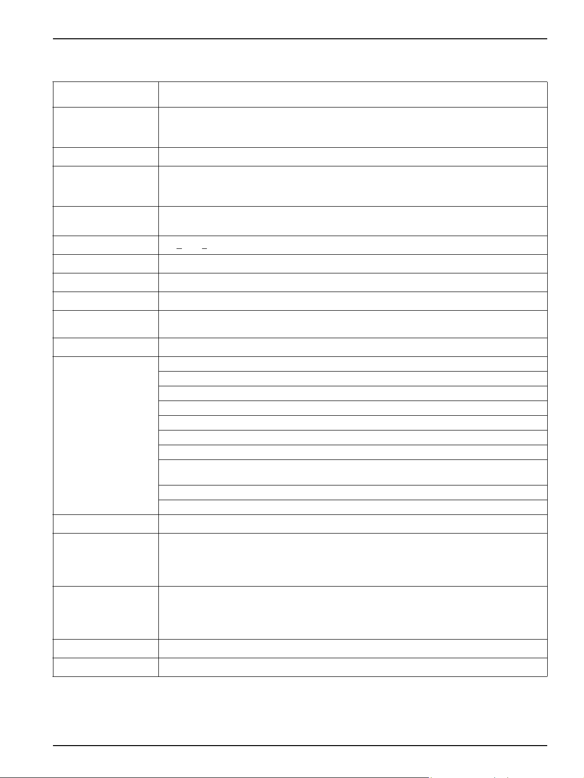
Section 1 Specifications
Specifications are subject to change without notice.
Measuring Technique
Measuring Range
Reproducibility Turbidity < 1 %, Total Suspended Solids (TSS) < 3 %
Measuring Accuracy
Technique variation
coefficient
Response Time 1s <
Calibration Zero point permanently set from the factory, gradient once for the TS content
Cable Length 10 m (33 ft), max. 100 m (328 ft) with extension cable
Ambient Temperature 0 to +40 °C (32 to 104 °F)
Pressure Range
Flow Velocity Max. 3 m/s (the presence of air bubbles affects the measurement)
Materials
Infrared Duo scattered light technique for color-independent turbidity measurement
Turbidity in accordance with DIN EN 27027 / TS equivalent DIN 38414
t-line turbidity: 0.001–4000 FNU/NTU
ts-line, inline turbidity: 0.001–4000 FNU/NTU; TSS content: 0.001 mg/L–50 g/L
hs-line, highline turbidity: 0.001–4000 FNU/NTU; TSS content: 0.001 mg/L–500 g/L TSS
Turbidity up to 1000 FNU/NTU:
without calibration < 5 % of the measured value ± 0.01 FNU/NTU
with calibration < 1 % of the measured value ± 0.01 FNU/NTU
1 % in accordance with DIN 38402
T90 < 300 s (adjustable)
Stainless steel: 6 bar or 60 m (87 psi)
PVC: 1 bar or 10 m (14,5 psi)
Optics carrier and sleeve: stainless steel 1.4571 or PVC black
Wiper shaft: stainless steel 1.4104
Wiper arm: stainless steel 1.4581
1
Wiper rubber: silicone rubber (standard) Optional: Viton
Windows and light guide: quartz glass
O-rings (optics carrier, wiper, windows): NBR (acrylonitrile butadiene rubber)
Housing seals: NBR 70
Sensor connecting cable (hard-wired): 1 cable pair AWG 22 / 12 V DC twisted, 1 cable pair AWG
24 / data twisted, common cable screen, Semoflex (PUR)
Sensor connection plug (hard-wired): type M12 enclosure rating IP 67
Threaded cable fitting: stainless steel 1.4305
(LZX578)
Inspection interval On request 1/year service contract with guarantee extension to 5 years
Tank probe: D x L 60 mm x 200 mm (2 x 8 in.)
Dimensions
Weight
User Maintenance 1 h / month, typical
Certifications CE
1
Viton® is a registered trademark of E.I. DuPont de Nemours + Co.
Probe for pipe installation: D x L 60 mm x 315 mm (2 x 12.4 in.)
(Pipe installation fitting: DN 65 / PN 16 DIN 2633; < 5 bar (73 psi); for pipes from DN 80)
Distance sensor - wall (floor): TS > 10 cm (4 in.), turbidity > 50 cm (20 in.)
Tank probe: approx. 1.8 kg (63 oz) (t-line: approx. 0.6 kg (21 oz))
Probe for pipe installation: approx. 2.4 kg (85 oz)
Pipe installation fitting: approx. 2.7 kg (95 oz) (without probe)
Pipe installation safety fitting:approx. 18 kg (40 lb) (without probe)
5
Page 6
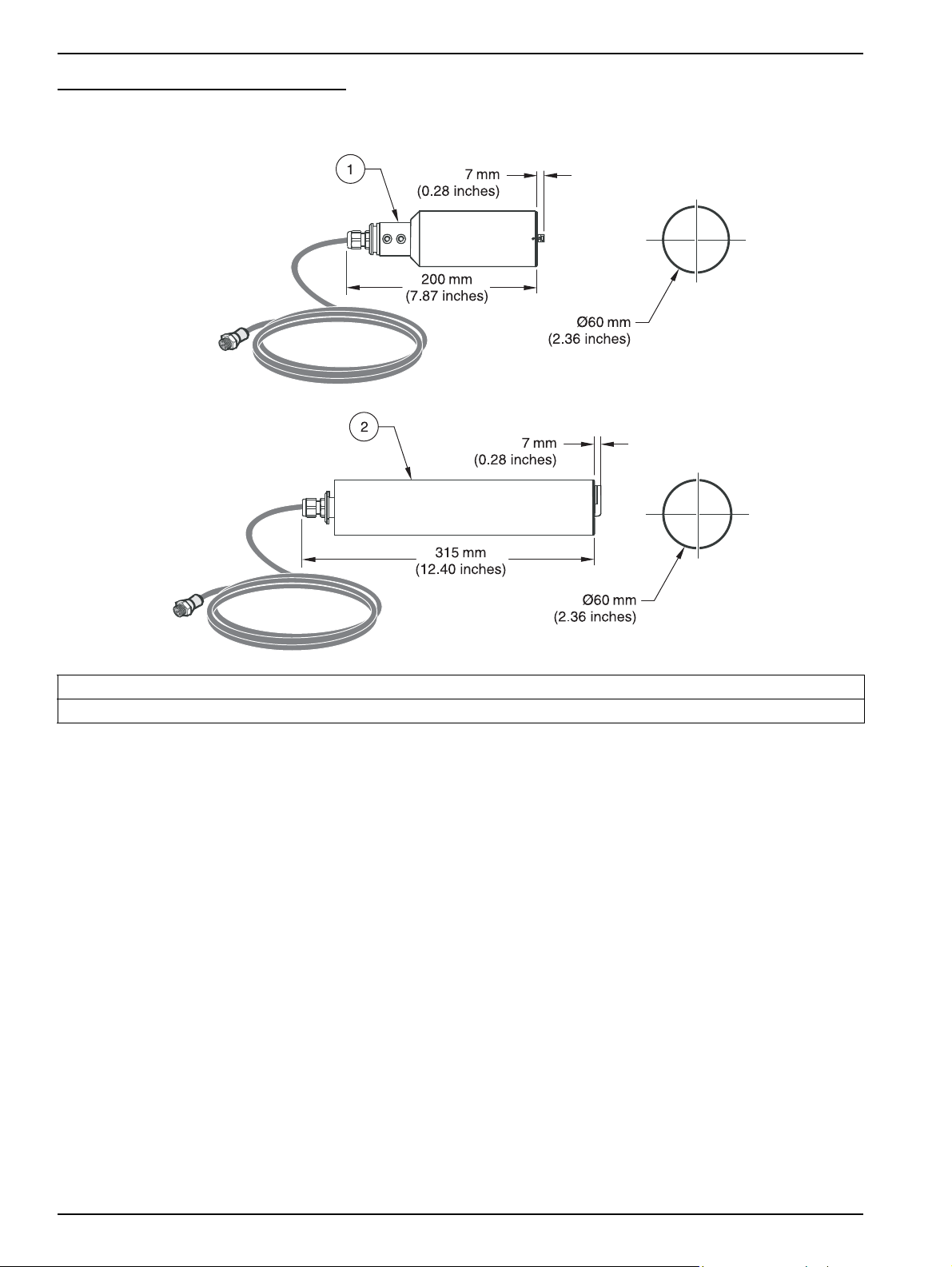
Specifications
Figure 1 Sensor Dimensions
1. SOLITAX sc models t-line, ts-line, and hs-line for immersion in open tanks
2. SOLITAX sc models inline and highline sensors for insertion in pipes
6
Page 7
Section 2 General Information
2.1 Safety Information
Please read this entire manual before unpacking, setting up, or operating this equipment.
Pay attention to all danger and caution statements. Failure to do so could result in serious
injury to the operator or damage to the equipment.
Make sure that the protection provided by this equipment is not impaired, do not use or
install this equipment in any manner other than that specified in this manual.
2.1.1 Use of Hazard Information
DANGER
Indicates a potentially or imminently hazardous situation which, if not avoided, will
result in death or serious injury.
CAUTION
Indicates a potentially hazardous situation that may result in minor or moderate
injury.
Important Note: Information that requires special emphasis.
Note: Information that supplements points in the main text.
2.1.2 Precautionary Labels
Read all labels and tags attached to the instrument. Personal injury or damage to the
instrument could occur if not observed
This symbol, if noted on the instrument, references the instruction manual for operation and/or safety information.
This symbol indicates that a risk of electrical shock and/or electrocution exists.
Electrical equipment marked with this symbol may not be disposed of in European public disposal systems after 12
August of 2005. In conformity with European local and national regulations (EU Directive 2002/96/EC), European
electrical equipment users must now return old or end-of life equipment to the Producer for disposal at no charge to
the user.
Note: For return for recycling, please contact the equipment producer or supplier for instructions on how to return
end-of-life equipment, producer-supplied electrical accessories, and all auxiliary items for proper disposal.
7
Page 8
General Information
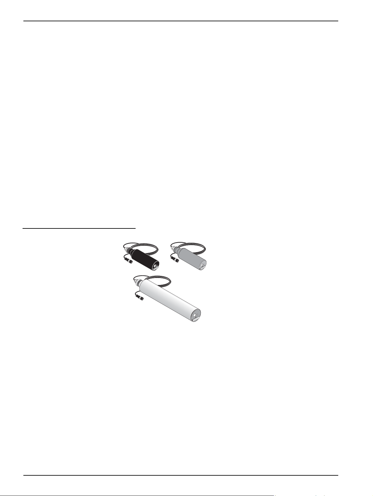
2.2 Sensor Overview
Note: All sensors are also available without wipers for special applications.
t-line: 0.001–4000 FNU/NTU
High-resolution turbidity probe made of plastic for the outlets of sewage treatment plants
and bodies of water.
ts-line: 0.001–4000 FNU/NTU; 0.001 mg/L–50.0 g/L
High-precision turbidity and solids probe made of stainless steel or plastic for
color-independent measurement of fine turbidities and sludges.
hs-line: 0.001–4000 FNU/NTU; 0.001 mg/L–500.0 g/L
High-precision turbidity and solids probe made of stainless steel or plastic for
color-independent measurement of highly concentrated sludges.
inline: 0.001–4000 FNU/NTU; 0.001 mg/L–50.0 g/L
High-precision pipe installation probe for turbidity and solids made of stainless steel for
color-independent measurement of fine turbidities and sludges.
highline: 0.001–4000 FNU/NTU; 0.001 mg/L–500.0 g/L
High-precision pipe installation probe for turbidity and suspended solids made of stainless
steel for color-independent measurement of highly concentrated sludges.
Figure 2 Solitax sc Sensors
2.3 Measuring Principle
The measuring principle is based on a combined infrared absorption scattered light
technique that measures the lowest turbidity values in accordance with DIN EN 27027 just
as precisely and continuously as high sludge content. Using this method, the light
scattered sideways by the turbidity particles is measured over an angle of 90°.
2.4 Handling
8
The sensor contains high-quality optical and electronic assemblies. Make sure the sensor
is not subjected to any hard mechanical knocks. There are no customer-serviceable items
inside the sensor.
Page 9
Section 3 Installation
Werksprüfzeugnis
nach DINEN10204-2.3
Sehrgeehrter Kunde,
IhrMeßgerät hatunser Werkin einwandfreiem undgeprüftem Zustandverlassen. DieGeräteprüfung erfolgte
nach einerDr.Lange Prüfanleitungdes nachDINEN ISO9001 zertifiziertenDr.LangeQualitätsmanagementsystems.
IhrMeßgerät entsprichtdenharmonisierten Normen:
-DIN EN50081-2(Störaussendung)
-DIN EN50082-2(Störfestigkeit)
-DIN EN61010-1(Sicherheitsbestimmungen)
Specific test report
accordingto EN10204-2.3
Dearcustomer,
yourinstrum enthasleft ourcompan yina perfectand inspectedcon dition.The instrumentcheck followsthe
Dr.Lange inspectionprocedureof thecertificatedDr.Lange-Qualitymanagementsystem(ISO 9001).Your
instrumentcorresponds totheharmonised standards:
-EN 50081-2(noiseemission)
-EN 50082-2(noiseimmunity)
-EN 61010-1(safetyrequirements)
Relevé de contrôle spécifique
selonla normeEN10204-2.3
Cherclient,
votreappar eilaquitt énotreusin econtrôllé estenpar faitétat deservice. Laprocédure decontrôle aété
réaliséselonle guidede Dr.Langeconformeà notresystèmede contrôledequalité (ISO9001).
L'appar eilest conformeaux normesharmon isés:
-EN 50081-2(Bruitd´emission)
-EN 50082-2(immunitéau bruit)
-EN 61010-1(Règlesde sécurités)
HDQ045
V1.0
DOC023.XX.03232.XXXyy
SOLITAX
Betriebsanleitung
1
2
3
4
DANGER
Only qualified personnel should conduct the tasks described in this section of the
manual.
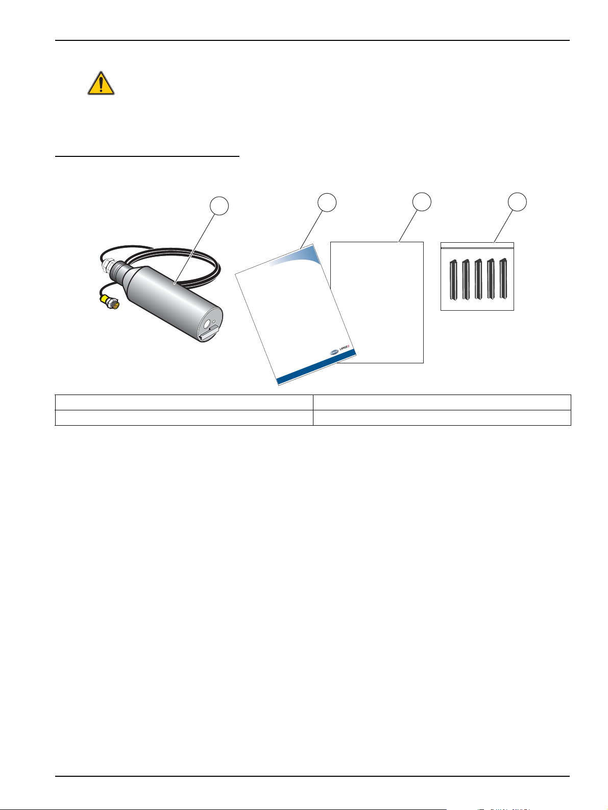
3.1 Unpacking the Instrument
Figure 3 Items Supplied with SensorI
1. SOLITAX sc Sensor 3. Factory Test Certificate
2. User Manual 4. Wiper Set (for 5 changes) LZX050
3.1.1 Function Check
After unpacking, both components should be checked for any transport damage and a
short function check performed prior to installation.
To perform a function check, connect the sensor to the display unit and power the unit.
Shortly after the unit is plugged in, the display is activated and the instrument switches to
the measurement display. Measured values taken in air is meaningless.
If no messages appear in the lower part of the display, the function check is
then complete.
9
Page 10

Installation
3.2 Sensor Installation
Figure 4 on page 10 illustrates the installation overview for Solitax sc Models t-line, ts-line,
and hs-line for immersion in open tanks.
The maximum distance from the mounting surface to the sensor without the use of an
extension tube is 1.5 m (4.9 ft). When that distance exceeds 1.5 m (4.9 ft), one of the
following extension tubes is required and can be ordered separately:
• 1.0 m (3.28 ft) extension pipe LZY413
• 1.8 m (5.90 ft) extension pipe LZY414
To ensure a suitable measuring position, install the probe to the following conditions:
• The probe optical window must have a ground clearance of at least 30 cm (11.8 in.).
• Install the probe with the optical window facing (downstream) in the direction of the
flow to minimize the risk of fouling.
• Avoid installation sites where air bubbles are inconsistent. If this not possible, try
moving the probe slightly or adjusting its alignment to minimize the bubble effect.
• Protect the probe against the oncoming flow of large objects, such as branches or ice
and against flow surges.
• Avoid installing the probe with the optical window facing into direct light or facing a
highly-reflective surface.
Figure 4 Sensor Installation Overview
10
Page 11

3.3 Pipe Installation
• Install the sensor in an up-flow pipe section for best results. Do not mount the sensor
in a down-flow pipe section.
• Mounting in a horizontal pipe section is acceptable if the sensor is fully immersed at all
times. Usually, mounting 90 degrees from the top of the pipe guarantees full
immersion. Do not mount on the top or bottom of a horizontal pipe section.
• Install the sensor in a pipe that is equal to or greater than 4 inches in diameter.
• Install the sensor at least 1.5 m (5 ft.) or three times the pipe diameter (whichever is
greater) downstream of pumps, valves, or pipe elbows.
• Install the sensor on the discharge side of a pump, if possible, with a dilution or flush
valve installed on the suction side of the pump.
• If the sensor is to be used to measure sludge with significant amounts of debris, install
it after a sludge grinding pump or after a pump with a grinding/comminuting unit in
front of it.
• Install the sensor within 7.8 m (25 ft.) of the controller with the standard probe cable.
Optional cable extensions can be added for a maximum combined distance of
100 meters (330 ft.).
Installation
• If the flange cannot be welded to the pipe due to incompatibility of materials between
the stud and the pipe, it is recommended that a stainless steel pipe section be
fabricated. Weld the flange onto the stainless steel pipe section and attach the
stainless steel section as a segment of the process pipe.
11
Page 12

Installation
Direction of Flow
Figure 5 Proper Positioning for Insertion into Pipe
12
Page 13

3.4 Connecting sensor cable
6
1 2
5
3
4
CAUTION
Always lay cables and hoses so they do not pose a trip hazard and are not bent.
1. Unscrew the protective cap on the controller socket and retain it.
2. Pay attention to the guide in the plug and push the plug into the socket.
3. Tighten the nuts.
Connector cables are available in various lengths (refer to Section 7 Replacement Parts
and Accessories on page 23). Maximum overall cable length: 50 m (165 ft).
Figure 6 Connection of the sensor plug to the controller
Installation
Figure 7 Sensor connector pin assignment
Number Description Cable colour (Standard-Cable)
1+12 VDC brown
2 Ground black
3Data (+) blue
4 Data (–) white
5 Screen Screen (grey)
6 Notch –
13
Page 14

Installation
14
Page 15

Section 4 Operations
4.1 Use of an sc controller
Before using the sensor in combination with an sc controller, refer to the controller user
manual for navigation information.
4.2 Sensor Setup
When a sensor is initially installed, the serial number of the sensor will be displayed as the
sensor name. To change the sensor name refer to the following instructions:
1. Select Main Menu.
2. From the Main Menu, select SENSOR SETUP and confirm.
3. Highlight the appropriate sensor if more than one sensor is attached and confirm.
4. Select CONFIGURE and confirm.
5. Select EDIT NAME and edit the name. Confirm or cancel to return to the Sensor
Setup menu.
4.3 Sensor Data Logging
A data memory and event memory per sensor are available via the sc controller. While
measured data are saved in the data memory at stipulated intervals, the event memory
collects numerous events such as configuration changes, alarms and warning conditions.
Both the data memory and the event memory can be read out in CSV format. For
information on how you can download the data, please see the controller manual.
4.4 Sensor Diagnostics Menu for pH and ORP
SELECT SENSOR (if more than one sensor is attached)
STATUS
ERROR LIST See section 6.1 on page 21.
WARNING LIST See section 6.2 on page 21..
4.5 Sensor Setup Menu
SELECT SENSOR (if more than one sensor is attached)
WIPE
Initiates a wiping action on the sensor window.
CALIBRATE
Select the behavior of the outputs during calibration for zero point setting (Hold, Active, Transfer,
SET OUTMODE
SENSOR MEASURE Displays the current, uncorrected measured value.
CONFIGURE
FACTOR/2 POINTS/
3 POINTS/4 POINTS/
5POINTS
SET CAL DEFAULT Return the instrument to the default calibration settings.
Selection). Hold maintains the last reading prior to going into the menu. Active transmits the
current level readings, corrected with previous calibration data until new data is entered. Set
Transfer transmits the value designated during the system setup
Select the calibration type and follow the calibration steps for 2 point, 3 point, 4 point, and 5 point
calibration.
Display depends on the selection in configuration.
15
Page 16

Operations
4.5 Sensor Setup Menu (continued)
CONFIGURE
EDIT NAME Enter up to a 10-digit name in any combination of symbols and alpha or numeric characters.
This setting configures the Solitax to measure turbidity or suspended solids. The Solitax cannot
SET PARAMETER
MEAS UNITS
CLEAN INTERVAL
RESPONSE TIME
LOGGER INTERVAL
SET DEFAULTS Resets all user-editable options to the factory-defaults.
TEST/MAIN
PROBE INFO
PROFILE
COUNTER Shows the number of hours or cycles left for operating hours, test/maint, gasket, and the motor.
TEST/MAIN
simultaneously measure both. Choose “TRB” for turbidity measurements, or “TS” for suspended
solids measurement. This selection determines which units may be selected in the “Meas Units”
menu.
Choose from the displayed units. TRB (FNU, EBC, TE/F, NTU); TS (mg/L, g/L, ppm, %)
Default: FNU
If TRB was selected in set parameter, select “NTU” (commonly used in the U.S.), FNU, EBC, or
TE/F. If TS was selected, choose mg/L, g/L, ppm, or %. Press enter to choose the selection. If
the units selected result in a reading that exceeds 4 digits, the display will only show dashes.
For example, if mg/L were selected, and the measurement was 10,500 mg/L, the display will
show dashes until the reading drops to 9999 or lower.
Select the cleaning interval (1, 5, 15 or 30 minutes; 1, 4, or 12 hours; 1, 3, 7 days)
Default: 12 hours
This is the interval between wiper cleaning of the sensor window. It is recommended to start with
a setting of 30 minutes. This time may be adjusted according to the application. If readings
continue to be accurate, try a longer interval. If not, shorten the interval.
This is a damping function. While the Solitax takes readings continually, it will average them
together over the period of the response time. Once the response time has elapsed, the
displayed reading, 4-20 outputs, and alarm status are updated. (0 to 300 seconds)
Default: 3 seconds
This is the datalog interval, with options from 1–15 minutes. Values logged are the average of
the all readings during the previous logging interval. The controller will hold approximately
360 days of readings for one sensor at 15 minute intervals, or 24 days at 1 minute intervals (and
proportional in between). Default:10 minutes
Displays the sensor type, entered name of the sensor (Default: sensor serial number), the sensor
serial number, the software version number, and the sensor driver version number.
Select Profile Counter to display the number of wipes made (from 20000 backwards). Select
Reset Config to manually reset the profile counter.
WIPE—Initiates the wiping action of the wiper.
SIGNALS—displays the signal outputs for the device.
OUTPUT MODE—Select the behavior of the instrument outputs (Hold, Active, Transfer,
Selection)
DEFAULT SETUP—Resets all user-editable options to the factory defaults.
4.6 Calibration
16
There are two calibration techniques; depending on whether turbidity or suspended solid
is required (refer to section 4.6.2 or section 4.6.3 on page 18). Before calibration,
determine the behavior of the 4–20 outputs and alarm relays while the user is in the
CALIBRATE menu (refer to section 4.6.1).
Page 17

4.6.1 Setting the Outmode
1. From the Main Menu, select SENSOR SETUP and press confirm.
2. Select the appropriate sensor if more than one is attached and confirm.
3. Select CALIBRATE and press confirm.
4. Select SET OUTMODE. Select the available Out Mode (Active, Hold, Transfer) and
confirm.
4.6.2 Calibration for Turbidity
Turbidity calibration requires the use of a Turbidity Standard Solution. The manufacturer
recommends the 800 NTU Turbidity Standard Solution (part of the calibration kit No.
57330-00). A zero-point calibration using deionized water is also recommended.
1. From the Main Menu, select SENSOR SETUP and press confirm.
2. Select the appropriate sensor if more than one is attached and confirm.
3. Select CALIBRATE and press confirm.
4. Select SENSOR MEASURE and confirm.
5. Place the sensor in the calibration cylinder with deionized water, mounting it with the
supplied clamp. The tip of the probe should be approximately 1-inch below the surface
of the water. Record the reading from the sensor measure display.
Operations
6. Select OFFSET. Multiply the reading obtained in step 5 and enter the value.
7. Select SENSOR MEASURE.
8. Rinse the outside of the StablCal
or debris adhering to the surface of the bottle. Gently invert both StablCal standard
bottles a minimum of 50 times. Remove the lid and seal from each bottle. Slowly (to
avoid creating bubbles) pour the contents of the bottles into the calibration cylinder.
Immediately place the tip of the probe into the positioning bracket in the calibration
cylinder. The tip of the probe should be approximately 1-inch below the surface
standard. Allow the reading to become stable on the SENSOR MEASURE screen.
Record the value (measured value). Calculate the factor. Refer to section 4.6.2.1.
9. Select FACTOR to display the corrected measurement.
4.6.2.1 Calculating the Factor
New Factor =
For example, if a sample measures 750 NTU using the sensor and the standard is
800 NTU, the new factor would be calculated as follows:
800 NTU Standard
measured value
®
800 NTU standard with water to remove any dust
New Factor =
800 NTU
750 NTU
= 1.07
17
Page 18

Operations
4.6.3 Calibration for Suspended Solids
Suspended solids calibration requires calibration to the actual sample. This optimizes the
compensation for the particle size and shape typical at a measuring site. It is best
performed by mounting the sensor as usual for normal measurement, and then grab
samples collected and evaluated by laboratory methods. While a single point calibration is
usually sufficient to provide accuracy, the SOLITAX does offer the ability to calibrate with
up to 5 calibration points.
1. From the Main Menu, select SENSOR SETUP and press confirm.
2. Select the appropriate sensor if more than one is attached and confirm.
3. Select CALIBRATE and press confirm.
4. Select CONFIGURE and confirm.
5. Select the number of points desired for calibration (the unit with linearly interpolate
values between calibration points). Select Factor for a single point calibration.
6. Mount the sensor as is during normal operation. Alternatively, place the sensor in the
calibration cylinder (or a container with dark, non-reflective walls) 2 inches of
clearance from the probe face with the probe face submerged by 1 inch or more.
7. Select SENSOR MEASURE and record the reading.
8. Immediately take a grab sample. Determine the total suspended solids using a
gravimetric method such as Method 2540 D in Standards Methods for the
Examination of Water and WasteWater.
9. Calculate the new factor. Refer to section 4.6.3.1 for single point (Factor) calibration.
Refer section 4.6.3.2 on page 18 for multiple point calibrations.
10. Select FACTOR and press confirm. The corrected measurement should be displayed.
4.6.3.1 For Single Point (Factor) Calibration
Calculate the new factor:
New Factor =
For example, if a sample measures 2.3 g/L using the SS sensor and the gravimetric value
was 2.0 g/L, the new factor would be calculated as follows:
New Factor =
Determined gravimetric value
measured value
2.0 g/L
2.3 g/L
= 0.87
4.6.3.2 Multi-point Calibration
1. Repeat steps 6–8 in section 4.6.3 on page 18 at different times to obtain different
measurements.
2. From the CONFIGURE menu, select the appropriate calibration point menu.
3. Enter the pairs of values for each reading, the target value being the laboratory
determined value, and the actual value being the reading that the SOLITAX produced
in step 5. The pairs should be entered in order from lowest values to highest.
18
Page 19

Section 5 Maintenance
DANGER
Only qualified personnel should conduct the tasks described in this section of the
manual.
Proper maintenance of the measuring windows in the sensor is critical for accurate
measurements. The measuring windows should be checked monthly for soiling and the
wiper checked for wear.
Important Note: The seals must be replaced every 2 years by the Service Department. If
the seals are not changed regularly, water may enter the probe head and seriously
damage the instrument.
5.1 Maintenance Schedule
Maintenance Task Duration
Visual inspection monthly
Check calibration
Inspection six months (counter)
Seal change every 2 years (counter)
Change wiper and reset counter as per counter (20000 cycles)
monthly
(depending on the ambient conditions)
5.2 Cleaning the Sensor Measuring Windows
CAUTION
Always were
Safety glasses,
Gloves and
Overal
handling hydrochloric acid and observe safety regulations.
The measuring windows are made of quartz glass. If necessary, they can be cleaned with
a cleaning agent and a cloth.
19
Page 20

Maintenance
1
4
2
3
5.3 Replacing the Wiper
The life of the wiper is dependent on the number of cleaning actions performed and the
type of deposits to be removed. The life of the wiper varies. The wipers supplied with the
instrument should last for approximately one year.
1. From the Main Menu, select SENSOR SETUP and press confirm.
2. Select the appropriate sensor if more than one is attached and confirm.
3. Select TEST/MAINT and press confirm.
4. Select PROFILE and confirm. Change the wiper, see section 5.3 on page 20.
5. Select RESET CONFIG and confirm.
6. Select MAN. RESET ARE YOU SURE? and confirm.
Figure 8 Wiper Replacement
1. Wiper arm 3. Wiper
2. M4 hex socket head bolt 4. Wiper axle
20
Page 21

Section 6 Troubleshooting
6.1 Error Codes
In the case of an error, the indication of the measured value flashes on the display and all
the contacts and current outputs allocated to this sensor are placed on hold. The following
conditions will result in flashing measured values:
• Data transmission between controller and sensor interrupted
On the Main menu open the SENSOR DIAG menu using ENTER and determine the
cause of the fault.
Table 1 Error Messages
Error Displayed Cause Solution
POS. UNKNOWN Wiper position unknown
LED FAULTY Faulty LED Contact customer service
MOIST Moisture value > 10
CAL. DATA Factory calibration data lost Contact customer service
6.2 Warnings
Open the TEST/MAINT menu and trigger the ”WIPE” function, if the
problem persists contact the manufacturer's customer service
Remove the sensor immediately and store in a dry place, contact
customer service
A warning results in a flashing warning icon on the right of the display, all menus, contacts
and outputs remain unaffected and continue to work normally. On the Main menu open the
SENSOR DIAG menu using ENTER and determine the cause of the warning.
A warning may be used to trigger a relay and users can set warning levels to define the
severity of the warning.
Table 2 Warnings
Warning Displayed Cause Solution
WARNING Cause Action
REPLACE WIPER Counter elapsed Replace wiper, reset counter
TEST/MAINT Counter elapsed Contact customer service
GASKET Counter elapsed Contact customer service
21
Page 22

Troubleshooting
22
Page 23

Section 7 Replacement Parts and Accessories
7.1 Immersion Sensors
Description Catalog Number
Turbidity, t-line sc, PVC with wiper (0.001 to 4000 NTU) LXV423.99.10000
Turbidity, t-line sc, PVC without wiper (0.001 to 4000 NTU) LXV423.99.12000
Turbidity and Suspended Solids, ts-line sc,
PVC with wiper (0.001 to 4000 NTU, 0.001 mg/L to 50 g/L)
Turbidity and Suspended Solids, ts-line sc,
PVC without wiper (0.001 to 4000 NTU, 0.001 mg/L to 50 g/L)
Turbidity and Suspended Solids, ts-line sc, stainless steel with wiper
(0.001 to 4000 NTU, 0.001 mg/L to 50 g/L)
Turbidity and Suspended Solids, ts-line sc, stainless steel without wiper
(0.001 to 4000 NTU, 0.001 mg/L to 50 g/L)
Turbidity and Suspended Solids, hs-line sc, PVC with wiper
(0.001 to 4000 NTU, 0.001 mg/L to 500 g/L)
Turbidity and Suspended Solids, hs-line sc, PVC without wiper
(0.001 to 4000 NTU, 0.001 mg/L to 500 g/L)
Turbidity and Suspended Solids, hs-line sc, stainless steel with wiper
(0.001 to 4000 NTU, 0.001 mg/L to 500 g/L)
Turbidity and Suspended Solids, hs-line sc, stainless steel without wiper
(0.001 to 4000 NTU, 0.001 mg/L to 500 g/L)
1
All sensors come with the sensor, replacement wipers, and manual.
1
LXV423.99.10100
LXV423.99.12100
LXV423.99.00100
LXV423.99.02100
LXV423.99.10200
LXV423.99.12200
LXV423.99.00200
LXV423.99.02200
7.2 Insertion Sensors
Description Catalog Number
Turbidity and Suspended Solids, inline sc, stainless steel with wiper
(0.001 to 4000 NTU, 0.001 mg/L to 50 g/L)
Turbidity and Suspended Solids, inline sc, stainless steel without wiper
(0.001 to 4000 NTU, 0.001 mg/L to 50 g/L)
Turbidity and Suspended Solids, highline sc, stainless steel with wiper
(0.001 to 4000 NTU, 0.001 mg/L to 500 g/L)
Turbidity and Suspended Solids, highline sc, stainless steel without wiper
(0.001 to 4000 NTU, 0.001 mg/L to 500 g/L)
1
All sensors come with the sensor, replacement wipers, and manual.
1
LXV424.99.00100
LXV424.99.02100
LXV424.99.00200
LXV424.99.02200
7.3 Replacement Parts
Description Catalog Number
Set of wipers (for 5 changes) made of silicone for normal applications LZX050
Set of wipers (for 5 changes) made of Viton for e. g. media containing oil LZX578
SOLITAX sc User Manual, english DOC023.52.03232
Extension cable, 5 m (16.4 ft) LZX848
Extension cable, 10 m (33 ft) LZX849
Extension cable, 15 m (50 ft) LZX850
Extension cable, 20 m (65 ft) LZX851
Extension cable, 30 m (100 ft) LZX852
Extension cable, 50 m (165 ft) LZX853
23
Page 24

Replacement Parts and Accessories
7.3 Replacement Parts (continued)
Description Catalog Number
Extension pipe, 1,0 m (3.28 ft) LZY413
Extension pipe, 1,8 m (5.90 ft) LZY414
Installation kit, fixed-point (for t-line, ts-line, and hs-line immersion sensors) LZX414.00.10000
Consisting of:
Base ATS010
Mounting plate HPL061
Holding clamp (2×) LZX200
Assembly pipe 2 m BRO075
HS small parts set LZX416
Installation kit with straight adapter LZX414.00.20000
Kit, screws and seals for sensor adapters LZX417
Miscellaneous hardware for probe installation kit LZX416
Second fastening point, includes: bracket, sensor pipe stand, sensor pipe stand bracket, screws,
and grommet)
Sensor fixed-point mounting kit: Sensor pipe bracket ATS010
Sensor pipe stand bracket LZX200
L-bracket ATS 011
Adapter, Sensor 90° elbow AHA034
Ball valve for insertion probes without adapting flange LZX337
Welded flange made of C-steel for the pipe installation fitting LZX703
Welded flange made of stainless steel for pipe installation safety fitting LZX660
LZX456
24
Page 25

Section 8 Contact Information
HACH Company
World Headquarters
P.O. Box 389
Loveland, Colorado
80539-0389 U.S.A.
Tel (800) 227-HACH
(800) -227-4224
(U.S.A. only)
Fax (970) 669-2932
orders@hach.com
www.hach.com
HACH LANGE GMBH
Willstätterstraße 11
D-40549 Düsseldorf
Tel. +49 (0)2 11 52 88-320
Fax +49 (0)2 11 52 88-210
info@hach-lange.de
www.hach-lange.de
HACH LANGE
Rorschacherstrasse 30 a
CH-9424 Rheineck
Tel. +41 (0)71 886 91 11
Fax +41 (0)71 886 91 66
info@hach-lange.ch
www.hach-lange.ch
Repair Service in the
United States:
HACH Company
Ames Service
100 Dayton Avenue
Ames, Iowa 50010
Tel (800) 227-4224
(U.S.A. only)
Fax (515) 232-3835
HACH LANGE LTD
Pacific Way
Salford
GB-Manchester, M50 1DL
Tel. +44 (0)161 872 14 87
Fax +44 (0)161 848 73 24
info@hach-lange.co.uk
www.hach-lange.co.uk
HACH LANGE FRANCE
S.A.S.
8, mail Barthélémy Thimonnier
Lognes
F-77437 Marne-La-Vallée
cedex 2
Tél. +33 (0)8 20 20 14 14
Fax +33 (0)1 69 67 34 99
info@hach-lange.fr
www.hach-lange.fr
Repair Service in Canada:
Hach Sales & Service
Canada Ltd.
1313 Border Street, Unit 34
Winnipeg, Manitoba
R3H 0X4
Tel (800) 665-7635
(Canada only)
Tel (204) 632-5598
Fax (204) 694-5134
canada@hach.com
HACH LANGE LTD
Unit 1, Chestnut Road
Western Industrial Estate
IRL-Dublin 12
Tel. +353(0)1 46 02 5 22
Fax +353(0)1 4 50 93 37
info@hach-lange.ie
www.hach-lange.ie
HACH LANGE SA
Motstraat 54
B-2800 Mechelen
Tél. +32 (0)15 42 35 00
Fax +32 (0)15 41 61 20
info@hach-lange.be
www.hach-lange.be
Repair Service in
Latin America, the
Caribbean, the Far East,
Indian Subcontinent, Africa,
Europe, or the Middle East:
Hach Company World
Headquarters,
P.O. Box 389
Loveland, Colorado,
80539-0389 U.S.A.
Tel +001 (970) 669-3050
Fax +001 (970) 669-2932
intl@hach.com
HACH LANGE GMBH
Hütteldorferstr. 299/Top 6
A-1140 Wien
Tel. +43 (0)1 9 12 16 92
Fax +43 (0)1 9 12 16 92-99
info@hach-lange.at
www.hach-lange.at
DR. LANGE NEDERLAND
B.V.
Laan van Westroijen 2a
NL-4003 AZ Tiel
Tel. +31(0)344 63 11 30
Fax +31(0)344 63 11 50
info@hach-lange.nl
www.hach-lange.nl
HACH LANGE APS
Åkandevej 21
DK-2700 Brønshøj
Tel. +45 36 77 29 11
Fax +45 36 77 49 11
info@hach-lange.dk
www.hach-lange.dk
HACH LANGE LDA
Av. do Forte nº8
Fracção M
P-2790-072 Carnaxide
Tel. +351 214 253 420
Fax +351 214 253 429
info@hach-lange.pt
www.hach-lange.pt
HACH LANGE KFT.
Vöröskereszt utca. 8-10.
H-1222 Budapest XXII. ker.
Tel. +36 (06)1 225 7783
Fax +36 (06)1 225 7784
info@hach-lange.hu
www.hach-lange.hu
HACH LANGE AB
Vinthundsvägen 159A
SE-128 62 Sköndal
Tel. +46 (0)8 7 98 05 00
Fax +46 (0)8 7 98 05 30
info@hach-lange.se
www.hach-lange.se
HACH LANGE SP.ZO.O.
ul. Opolska 143 a
PL-52-013 Wrocław
Tel. +48 (0)71 342 10-83
Fax +48 (0)71 342 10-79
info@hach-lange.pl
www.hach-lange.pl
HACH LANGE S.R.L.
Str. Căminului nr. 3
Sector 2
RO-021741 Bucureşti
Tel. +40 (0) 21 205 30 03
Fax +40 (0) 21 205 30 17
info@hach-lange.ro
www.hach-lange.ro
HACH LANGE S.R.L.
Via Riccione, 14
I-20156 Milano
Tel. +39 02 39 23 14-1
Fax +39 02 39 23 14-39
info@hach-lange.it
www.hach-lange.it
HACH LANGE S.R.O.
Lešanská 2a/1176
CZ-141 00 Praha 4
Tel. +420 272 12 45 45
Fax +420 272 12 45 46
info@hach-lange.cz
www.hach-lange.cz
HACH LANGE
8, Kr. Sarafov str.
BG-1164 Sofia
Tel. +359 (0)2 963 44 54
Fax +359 (0)2 866 15 26
info@hach-lange.bg
www.hach-lange.bg
HACH LANGE S.L.U.
Edif. Arteaga Centrum
C/Larrauri, 1C- 2ª Pl.
E-48160 Derio/Vizcaya
Tel. +34 94 657 33 88
Fax +34 94 657 33 97
info@hach-lange.es
www.hach-lange.es
HACH LANGE S.R.O.
Roľnícka 21
SK-831 07 Bratislava –
Vaj nory
Tel. +421 (0)2 4820 9091
Fax +421 (0)2 4820 9093
info@hach-lange.sk
www.hach-lange.sk
HACH LANGE SU
ANALİZ SİSTEMLERİ
LTD. ŞTİ.
Hilal Mah. 75. Sokak
Arman Plaza No: 9/A
TR-06550 Çankaya/ANKARA
Tel. +90 (0)312 440 98 98
Fax +90 (0)312 442 11 01
bilgi@hach-lange.com.tr
www.hach-lange.com.tr
25
Page 26

Contact Information
HACH LANGE D.O.O.
Fajfarjeva 15
SI-1230 Domžale
Tel. +386 (0)59 051 000
Fax +386 (0)59 051 010
info@hach-lange.si
www.hach-lange.si
HACH LANGE MAROC
SARLAU
Villa 14 – Rue 2 Casa
Plaisance
Quartier Racine Extension
MA-Casablanca 20000
Tél. +212 (0)522 97 95 75
Fax +212 (0)522 36 89 34
info-maroc@hach-lange.com
www.hach-lange.ma
ΗΑCH LANGE E.Π.Ε.
Αυλίδος 27
GR-115 27 Αθήνα
Τηλ. +30 210 7777038
Fax +30 210 7777976
info@hach-lange.gr
www.hach-lange.gr
HACH LANGE E.P.E.
27, Avlidos str
GR-115 27 Athens
Tel. +30 210 7777038
Fax +30 210 7777976
info@hach-lange.gr
www.hach-lange.gr
HACH LANGE D.O.O.
Ivana Severa bb
42 000 Varaždin
Tel. +385 (0) 42 305 086
Fax +385 (0) 42 305 087
info@hach-lange.hr
www.hach-lange.hr
26
Page 27

Section 9 Warranty and liability
The manufacturer warrants that the product supplied is free of material and manufacturing
defects and undertakes the obligation to repair or replace any defective parts at zero cost.
The warranty period for instruments is 24 months. If a service contract is taken out within
6 months of purchase, the warranty period is extended to 60 months.
With the exclusion of the further claims, the supplier is liable for defects including the lack
of assured properties as follows: all those parts that, within the warranty period calculated
from the day of the transfer of risk, can be demonstrated to have become unusable or that
can only be used with significant limitations due to a situation present prior to the transfer
of risk, in particular due to incorrect design, poor materials or inadequate finish will be
improved or replaced, at the supplier's discretion. The identification of such defects must
be notified to the supplier in writing without delay, however at the latest 7 days after the
identification of the fault. If the customer fails to notify the supplier, the product is
considered approved despite the defect. Further liability for any direct or indirect damages
is not accepted.
If instrument-specific maintenance and servicing work defined by the supplier is to be
performed within the warranty period by the customer (maintenance) or by the supplier
(servicing) and these requirements are not met, claims for damages due to the failure to
comply with the requirements are rendered void.
Any further claims, in particular claims for consequential damages cannot be made.
Consumables and damage caused by improper handling, poor installation or incorrect use
are excluded from this clause.
The manufacturer process instruments are of proven reliability in many applications and
are therefore often used in automatic control loops to provide the most economical
possible operation of the related process.
To avoid or limit consequential damage, it is therefore recommended to design the control
loop such that a malfunction in an instrument results in an automatic change over to the
backup control system; this is the safest operating state for the environment and the
process.
27
Page 28

Warranty and liability
28
Page 29

Appendix A Modbus Register Information
Table 3 Sensor Modbus Registers
Group Name Tag Name Register Data Type# Length R/W Description
Measurements TurbidityFNU 40001 Float 2 R Turbidity FNU
Measurements TurbidityEBC 40003 Float 2 R Turbidity EBC
Measurements SolidsMGL 40005 Float 2 R Solids mg/L
Measurements SolidsGL 40007 Float 2 R Solids g/L
Measurements SolidsPR 40009 Float 2 R Solids %
— Reserved 40011 Unsigned Integer 1 R Reserved
Base Parameter 40012 Unsigned Integer 1 R/W Parameter
Base UnitTRB 40013 Unsigned Integer 1 R/W Unit Turbidity
Base UnitTS 40014 Unsigned Integer 1 R/W Units Solids
Calibration OffsetTRB 40015 Float 2 R/W Turbdity Offset
Calibration FactorTRB 40017 Float 2 R/W Turbidity Factor
Calibration FactorTS 40019 Float 2 R/W Solids Factor
Data Wiperstate 40021 Unsigned Integer 1 R/W Wiper register
Setup ResponseInterval 40022 Unsigned Integer 1 R/W Response time
Setup CleaningInterval 40023 Unsigned Integer 1 R/W Wiper interval
Setup LogInterval 40024 Unsigned Integer 1 R/W Logger interval
Setup Outputmodekal 40025 Unsigned Integer 1 R/W Output when calibrate
Setup Outputmodesrv 40026 Unsigned Integer 1 R/W Output when service
Setup Location 40027 String 8 R/W Edited name
Setup ProfilCounter 40035 Unsigned Integer 1 R/W Profi counter
Data SerienNummer 40036 String 6 R Serial number
Calibration DateUserCal 40042 Date 2 R
Calibration DateUserCalTURB 40044 Date 2 R Date of calibration turbidity
Calibration DateUserCalSOLID 40046 Date 2 R Date of calibration solid
Data VersionAppl 40048 Float 2 R Version application
Data VersionBoot 40050 Float 2 R Version Bootlader
Data VersionStruct 40052 Unsigned Integer 1 R Version structure probedriver
Data VersionContent 40053 Unsigned Integer 1 R Version register probedriver
Data VersionFirmware 40054 Unsigned Integer 1 R Version firmware probedriver
Data FormatMinFNU 40055 Float 2 R Minimum turbidity FNU
Data FormatMaxFNU 40057 Float 2 R Maximum turbidity FNU
Data FormatMinEBC 40059 Float 2 R Minimum turbidity EBC
Data FormatMaxEBC 40061 Float 2 R Maximum turbidity EBC
Data FormatMinGL 40063 Float 2 R Minimum solids g/L
Data FormatMaxGL 40065 Float 2 R Maximum solids g/L
Data FormatMinMGL 40067 Float 2 R Minimum solids mg/L
Data FormatMaxMGL 40069 Float 2 R Maximum mg/L
Data FormatMinPR 40071 Float 2 R Minimum solids %
Data FormatMaxPR 40073 Float 2 R Maximum solids %
Data SignalsLED 40075 Unsigned Integer 1 R Signal LED
Data SignalsMoist 40076 Unsigned Integer 1 R Signal moist
Date of manufacturing
calibration
29
Page 30

Modbus Register Information
30
 Loading...