

Page 1
Instruction Sheet
Sipper module
Safety Information
Please read this entire document before unpacking, setting up, or operating this
equipment. Pay attention to all danger and caution statements. Failure to do so could
result in serious injury to the operator or damage to the equipment.
To ensure that the protection provided by this equipment is not impaired, do not use or
install this equipment in any manner other than that specified in this document.
Use of Hazard Information
DANGER
Indicates a potentially or imminently hazardous situation which, if not avoided, will
result in death or serious injury.
WARNING
Indicates a potentially or imminently hazardous situation which, if not avoided,
could result in death or serious injury.
DOC272.53.90004
CAUTION
Indicates a potentially hazardous situation that may result in minor or moderate
injury.
Important Note: Indicates a situation which, if not avoided, may cause damage to the
instrument. Information that requires special emphasis.
Note: Information that supplements points in the main text.
Precautionary Labels
Read all labels and tags attached to the instrument. Personal injury or damage to the
instrument could occur if not observed. A symbol, if noted on the instrument, will be
included with a danger or caution statement in the manual.
Electrical equipment marked with this symbol may not be disposed of in European public di sposal systems after 12
August of 2005. In conformity with European local and national regulations (EU Directive 2002/96/EC), European
electrical equipment users must now return old or end-of life equipment to the Producer for disposal at no charge to
the user.
Note: For return for recycling, please contact the equipment producer or supplier for instructions on how to return
end-of-life equipment, producer-supplied electrical accessories, and all auxiliary items for proper disposal.
The Sipper Module uses a peristaltic pump to pull samples into a flow cell for readings.
After the reading is taken, the sample is either returned to the user or dumped to waste.
The Sipper Module provides improved measurement accuracy, because the sam e optical
characteristics exist for both blanking and reading, and when comparing me asurements o f
different samples. Errors resulting from optical differences between individual cells are
eliminated because every reading is taken in the same vial.
1
Page 2
Sipper module
Specifications
Specifications are subject to change without notice.
Available Path Leng ths
Wavelength Range
Rinsing Volume
Flow Rate
Storage Temperat ur e
Operating Temperature
2.42 cm (1 in.); 1 cm (0.394 in.)
190 to 1100 nm
At least 20 mL for 1-inch path length; at least 10 mL for 1-cm path length
1 mL/second (nominal)
–17 to 60 °C, 85% relative humidity, non-condensing
10 to 40 °C; 95% relative humidity, non-condensing at 25 °C; 75% relative humidity,
non-condensing at 40°C
Unpacking the sipper module
Remove the Sipper Module from the shipping container and inspect it for any damage that
may have occurred during shipment. All models are shipped with
• Sipper Module
• Sipper Accessories Kit
If any of these items are missing or damaged, contact the manufacturer or a sales
representative immediately.
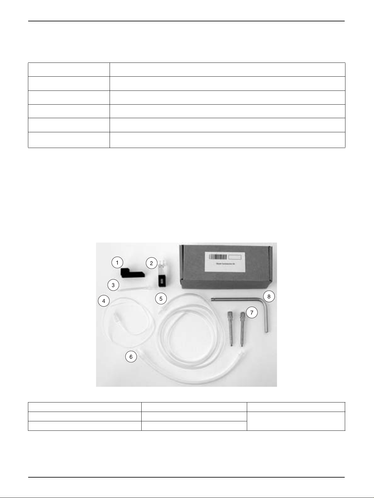
Figure 1 Sipper accessories kit
1 Rubber Fitting 4 Sample/Inlet Tubing 7 Locking Screws (2)
2 Sipper Cell, 1-cm 5 Drain/Waste Tubing 8 Guide Tube
3 Outlet Connector (from pump to drain) 6 Pump Tubing (white)
2
Page 3
Sipper module installation
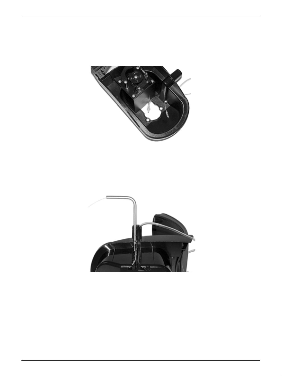
1. Pull the drain tube through the exit channel of the sipper from the inside outward s. Pull
the inlet tube through the entry channel of the sipper mod ule from the outside inwa rds.
The push-in connectors must be inside the module. Avoid kinks in the tubes.
Figure 2 Drain tube and inlet tube installation
Sipper module
2. Turn the sipper module on its side. Pull the inlet tube through the entry channel , and
the drain tube through the exit channel of the sipper. The inlet tube must be pulled
through the metal guide tube. The bottom end of the guide tube must click into the
channel. Avoid kinks in the tubes.
Figure 3 Guide tube installation
3. Hold the rubber fitting with the ridges over the grooves and push it firmly onto the
guide tube and the waste tube.The rubber fitting must firmly enclose the guide tube
and drain tube.
3
Page 4
Sipper module
Figure 4 Rubber fitting installation
4. Open the cell compartment. Without the locking screws, insert the Multi Cell Holder
into the cell compartment (refer to the user manual).
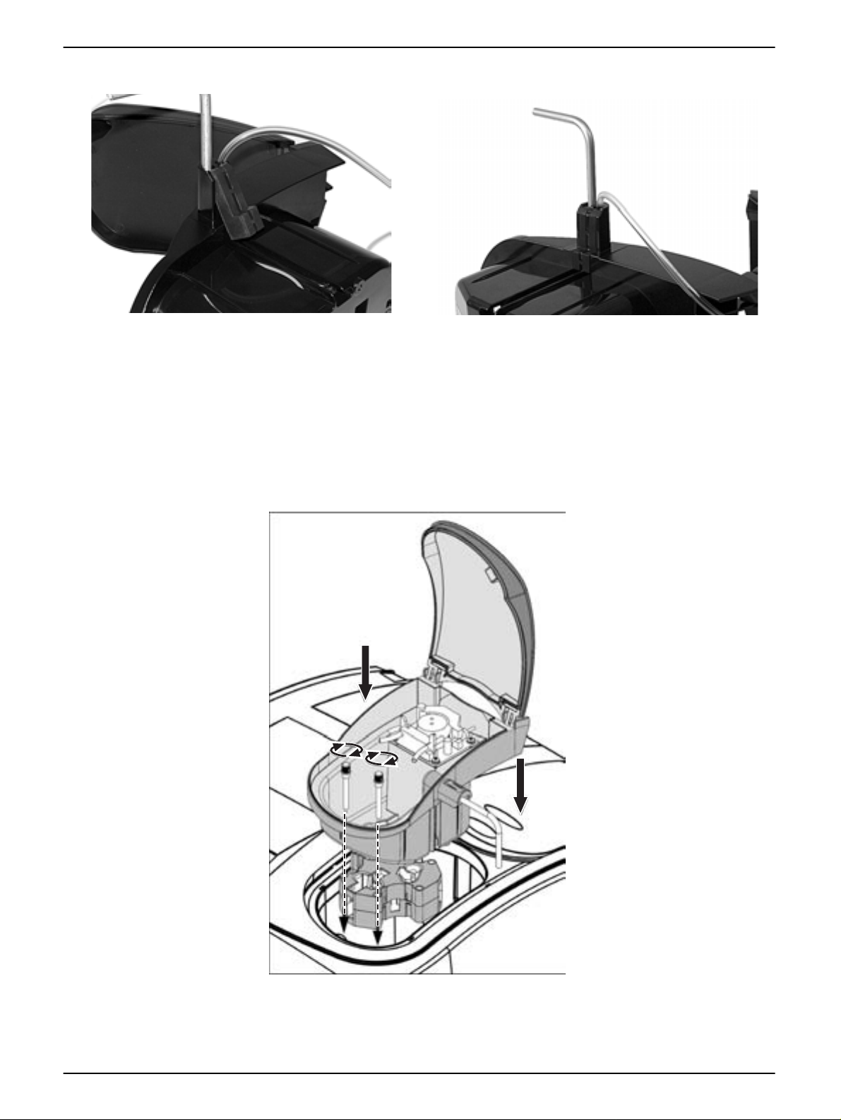
5. Place the Sipper Module on the Multi Cell Holder in such a way that the screw holes
are positioned exactly one above the other and the top of the lid of the Sipper Module,
when opended, will be facing towards the back of the instrument.
Figure 5 Place the Sipper modul
4
Page 5

Sipper module
6. Secure the Sipper Module and the Multi Cell Holder with the two locking screws
(Figure 1 on page 2).
7. Contact with instrument has now been established.
in Instrument Setup.
8. Pull the pump adjustment forward (item 1, Figure 6 on page 5) and open the pump
tubing clamp (item 2, Figure 6 ). Wrap the white pump tubing around the pump and
clamp the ends on the right and left in the two front retainers (item 3, Figure 6).The
push-in connectors of the pump tubing must be positioned as in Figure 6.
9. Clean the Sipper Cell with a lint-free cloth and insert the Sipper Cell (item 1, Figure 7
on page 6).
10. Use the outlet connector (item 2, Figure 7) to join the white pump tubing
(item 3, Figure 7) to the Sipper Cell outlet (item 1, Figure 7).
11. Connect the drain tube (item 5, Figure 7) to the right end of the white pump tubing.
12. Connect the inlet tube to the inlet of the Sipper Cell (item 4, Figure 7).
SIPPER OPTIONS is now available
Figure 6 Pump Adjustment
1 Pump Adjust Forward 2 Pump Tubing Clamp 3 Front Retainers
5
Page 6

Sipper module
Figure 7 Sipper module with tubes in place
1 Pump Tubing (white) 4 Sample/Inlet Tubing
2 Drain/Waste Tubing 5 Pour-Thru Cell
3 Guide tube 6 Outlet Connector (from pump to drain)
Sipper Module Setup
When a Sipper Module is installed, SIPPER OPTIONS icon is available in Instrument Setup.
1. From Instrument Setup, press
2. Enter the times for the listed parameters.
SIPPER OPTIONS.
6
Page 7

Sipper module
Automatic Mode
The characteristics of the three basic sipper cycles can be defined in the automatic mode:
Sip Time, Settle Time, and Purge Time.
• Sip Time: The sip time and the pump setting determin e the sample volume that can
be pumped into the cell.
• Settle Time: The settle time is the interval that must be allowed before the
measurement is performed. During this time, air bubbles that may have formed during
pumping can be eliminated, and any turbulence in the sample can settle.
• Purge Time: The purge time determines the volume of air or purging solution that is
pumped through the cell after the measurement.
Note: If the Sipper Module is not in automatic mode, press the PURGE START: MANUAL key to
change the mode to Auto.
Press ZERO or READ to run the programs through the sipper cycles automatically. Press
READ to run the program through the Sipper Module.
Manual Mode
In the manual Sipper mode, the purge cycles can be activated manually. This mode can
be useful during the input of the basic parameters, as an aid to determining which
parameter values to work with in the automatic mode.
7
Page 8

Sipper module
Performing a Single or Multi-Wavelength Measurement
1. Load and insert the Sipper Module. The SIPPER OPTIONS key will appear on the
Instrument Setup screen.
2. Press
SIPPER OPTIONS to select the Sipper Settings. Select the sipper settings and
press OK.
3. Press
OPTIONS on the Single or Multi-Wavelength menu to configure the parameters.
4. Route the drain tube to an appropriate drain or collection vessel.
5. Place the Sample Inlet Tube into th e blank and press
ZERO. Leave the inlet tube in the
sample until the Sipper Pump stops and the settling cycle begins.
Note: The remaining time in seconds is shown instead of the date on the display. Press
CANCEL to stop the sip cycle.
6. When the settling cycle is complete, the blank is displayed. In the automatic mode, the
purge begins immediately after the reading without operator intervention. If the purge
is set up for a manual start, the instrument will wait for the operator to press
Note: Distilled water or the sample can be used as the rinsing liquid.
PURGE.
7. Rather than wasting the sample, a distilled water purge can be placed at the sample
inlet to rinse the sample cell between readings.
8
Page 9

Sipper module
8. Leave the inlet tube in the purge solution until the Sipper pump stops.
Note: The remaining time in seconds is shown instead of the date on the display. Press
CANCEL during the purge interval to stop the purge cycle.
9. When the sample purge is complete the instrument is ready for the next sample.
Note: After starting the Reading sequence the ZERO/READ keys turn into a CANCEL key . P ress
CANCEL at any time to start over and to erase all readings from the current set of
measurements.
Performing a Wavelength Scan
1. Load and insert the Sipper Module. The SIPPER OPTIONS key will appear on the
Instrument Setup screen.
2. Press
3. Press
4. After the scanning parameters have been sele cted, the baseline must be scanned.
SIPPER OPTIONS to select the Sipper Settings. Select the sipper settings and
press OK.
OPTIONS on the Wavelength Scan menu to configure scanning parameters
Changing any of the scanning parameters requires a new baseline scan. When the
baseline has been scanned, the instrument is ready to scan the samples.
5. Route the drain tube to an appropriate drain or collection vessel.
6. Place the sample inlet tube into the blank and press
ZERO. Leave the inlet tube in the
sample until the Sipper pump stops and the settling cycle begins. The remaining time
in seconds is shown instead of the date on the display. Press
CANCEL to stop the sip
cycle.
9
Page 10

Sipper module
7. When the settling cycle is complete, the blank is displayed. In automatic mode, the
purge begins immediately after the reading. If the purge is set up for a manual start
the instrument will wait for the operator to press
Note: Distilled water or the sample can be used as the rinsing liquid.
8. Leave the inlet tube in the purge solution until the Sipper pump stops. The remaining
time in seconds is shown instead of the date on the display. Pre ss
purge interval to stop the purge cycle.
9. When the sample purge is complete the instrument is ready for the next sample.
Note: After starting the Reading sequence the ZERO/READ keys turn into a CANCEL key. Press
CANCEL at any time to start over and to erase all readings from the current set of
measurements.
Performing a Time Scan
1. Load and insert the Sipper Module. The SIPPER OPTIONS key will appear on the
Instrument Setup screen.
PURGE.
CANCEL during the
2. Press
SIPPER OPTIONS to select the Sipper Settings. Select the sipper settings and
press OK.
3. Press
OPTIONS on the Time Course menu to configure scanning p arameters. After th e
parameters have been selected, the instrument must be bla nked.
4. Route the drain tube to an appropriate drain or collection vessel.
5. Place the sample inlet tube into the blank and press
ZERO. Leave the inlet tube in the
sample until the Sipper pump stops and the settling cycle begins. The Remaining time
in seconds is shown instead of the date on the display. Press
CANCEL to stop the sip
cycle.
6. When the settling cycle is complete, the blank is displayed. In the automatic mode, the
purge begins immediately after the reading without operator intervention. If the purge
is set up for a manual start the instrument will wait for the operator to press
Note: Distilled water or the sample can be used as the rinsing liquid.
PURGE.
7. Leave the inlet tube in the purge solution until the Sipper pump stops. The remaining
time in seconds is shown instead of the date on the display. Pre ss
CANCEL during the
purge interval to stop the purge cycle.
10
Page 11

8. When the sample purge is complete the instrument is ready for the next sample.
Note: After starting the Reading sequence the ZERO/READ keys turn into a MARK/STOP key.
Press STOP at any time to start over.
Cleaning the Sipper Module
Sample Cell
Purge the cell with deionized water before and after each test session. If the cell is
unusually dirty, repeat the sip and purge cycles several times with deionized water, or
temporarily set the purge cycle to a higher setting befor e a djusting th e timing p a ra meters .
Occasionally inspect the sample cell windows. If the windows appear dirty or hazy,
remove the sample cell and soak it in a soap solution or dilute acid and rinse thoroughly
with deionized water.
Module
If the module becomes dirty, wipe it clean with soap, water, and a soft cloth. DO NOT
immerse the module or use solvents (e.g. acetone) to clean the module.
Cleaning the Tubes
The tubes should always be cleaned with deionized or distilled water after a measurement
series has been completed.
Sipper module
The discharge tube in the pump zone and the sipper tube are subject to mechanical and
chemical stresses and must be replaced. The number of op erating hours for th e tube set s
depends on the type of pumped solutions.
11
Page 12

Contact Information
HACH Company
World Headquarters
P.O. Box 389
Loveland, Colorado
80539-0389 U.S.A.
Tel (800) 227-HACH
(800) -227-4224
(U.S.A. only)
Fax (970) 669-2932
orders@hach.com
www.hach.com
HACH LANGE GMBH
Willstätterstraße 11
D-40549 Düsseldorf
Tel. +49 (0)2 11 52 88-320
Fax +49 (0)2 11 52 88-210
info@hach-lange.de
www.hach-lange.de
DR. BRUNO LANGE AG
Juchstrasse 1
CH-8604 Hegnau
Tel. +41(0)44 9 45 66 10
Fax +41(0)44 9 45 66 76
info@hach-lange.ch
www.hach-lange.ch
Repair Service in the
United States:
HACH Company
Ames Service
100 Dayton Avenue
Ames, Iowa 50010
Tel (800) 227-4224
(U.S.A. only)
Fax (515) 232-3835
HACH LANGE LTD
Pacific Way
Salford
GB-Manchester, M50 1DL
Tel. +44 (0)161 872 14 87
Fax +44 (0)161 848 73 24
info@hach-lange.co.uk
www.hach-lange.co.uk
HACH LANGE FRANCE
S.A.S.
33, Rue du Ballon
F-93165 Noisy Le Grand
Tél. +33 (0)1 48 15 68 70
Fax +33 (0)1 48 15 80 00
info@hach-lange.fr
www.hach-lange.fr
Repair Service in Canada:
Hach Sales & Service
Canada Ltd.
1313 Border Street, Unit 34
Winnipeg, Manitoba
R3H 0X4
Tel (800) 665-7635
(Canada only)
Tel (204) 632-5598
Fax (204) 694-5134
canada@hach.com
HACH LANGE LTD
Unit 1, Chestnut Road
Western Industrial Estate
IRL-Dublin 12
Tel. +353(0)1 46 02 5 22
Fax +353(0)1 4 50 93 37
info@hach-lange.ie
www.hach-lange.ie
HACH LANGE SA
Motstraat 54
B-2800 Mechelen
Tél. +32 (0)15 42 35 00
Fax +32 (0)15 41 61 20
info@hach-lange.be
www.hach-lange.be
Repair Service in
Latin America, the
Caribbean, the Far East,
Indian Subcontinent, Africa,
Europe, or the Middle East:
Hach Company World
Headquarters,
P.O. Box 389
Loveland, Colorado,
80539-0389 U.S.A.
Tel +001 (970) 669-3050
Fax +001 (970) 669-2932
intl@hach.com
HACH LANGE GMBH
Hütteldorferstr. 299/Top 6
A-1140 Wien
Tel. +43 (0)1 9 12 16 92
Fax +43 (0)1 9 12 16 92-99
info@hach-lange.at
www.hach-lange.at
DR. LANGE NEDERLAND
B.V.
Laan van Westroijen 2a
NL-4003 AZ Tiel
Tel. +31(0)344 63 11 30
Fax +31(0)344 63 11 50
info@hach-lange.nl
www.hach-lange.nl
HACH LANGE APS
Åkandevej 21
DK-2700 Brønshøj
Tel. +45 36 77 29 1 1
Fax +45 36 77 49 11
info@hach-lange.dk
www.hach-lange.dk
HACH LANGE LDA
Av. do Forte nº8
Fracção M
P-2790-072 Carnaxide
Tel. +351 214 253 420
Fax +351 214 253 429
info@hach-lange.pt
www.hach-lange.pt
HACH LANGE KFT.
Hegyalja út 7-13.
H-1016 Budapest
Tel. +36 (06)1 225 7783
Fax +36 (06)1 225 7784
info@hach-lange.hu
www.hach-lange.hu
HACH LANGE AB
Vinthundsvägen 159A
SE-128 62 Sköndal
Tel. +46 (0)8 7 98 05 00
Fax +46 (0)8 7 98 05 30
info@hach-lange.se
www.hach-lange.se
HACH LANGE SP.ZO.O.
ul. Opolska 143 a
PL-52-013 Wrocław
Tel. +48 (0)71 342 10-83
Fax +48 (0)71 342 10-79
info@hach-lange.pl
www.hach-lange.pl
HACH LANGE S.R.L.
Str. Leonida, nr. 13
Sector 2
RO-020555 Bucuresti
Tel. +40 (0) 21 201 92 43
Fax +40 (0) 21 201 92 43
info@hach-lange.ro
www.hach-lange.ro
HACH LANGE S.R.L.
Via Riccione, 14
I-20156 Milano
Tel. +39 02 39 23 14-1
Fax +39 02 39 23 14-39
info@hach-lange.it
www.hach-lange.it
HACH LANGE S.R.O.
Lešanská 2a/1176
CZ-141 00 Praha 4
Tel. +420 272 12 45 45
Fax +420 272 12 45 46
info@hach-lange.cz
www.hach-lange.cz
HACH LANGE
8, Kr. Sarafov str.
BG-1164 Sofia
Tel. +359 (0)2 963 44 54
Fax +359 (0)2 866 04 47
info@hach-lange.bg
www.hach-lange.bg
HACH LANGE S.L.U.
Edif. Arteaga Centrum
C/Larrauri, 1C- 2ª Pl.
E-48160 Derio/Vizcaya
Tel. +34 94 657 33 88
Fax +34 94 657 33 97
info@hach-lange.es
www.hach-lange.es
HACH LANGE S.R.O.
Roľnícka 21
SK-831 07 Bratislava –
Vajnory
Tel. +421 (0)2 4820 9091
Fax +421 (0)2 4820 9093
info@hach-lange.sk
www.hach-lange.sk
HACH LANGE SU
ANALİZ SİSTEMLERİ
LTD.ŞTİ.
Hilal Mah. 75. Sokak
Arman Plaza No: 9/A
TR-06550 Çankaya/ANKARA
Tel. +90 (0)312 440 98 98
Fax +90 (0)312 442 11 01
bilgi@hach-lange.com.tr
www.hach-lange.com.tr
HACH LANGE D.O.O.
Fajfarjeva 15
SI-1230 Domžale
Tel. +386 (0)59 051 000
Fax +386 (0)59 051 010
info@hach-lange.si
www.hach-lange.si
© Hach Company, 2008 Edition 1 June 2008 as/sk
ΗΑCH LANGE E.Π.Ε.
Αυλίδος 27
GR-115 27 Αθήνα
Τηλ. +30 210 7777038
Fax +30 210 7777976
info@hach-lange.gr
www.hach-lange.gr
HACH LANGE E.P.E.
27, Avlidos str
GR-115 27 Athens
Tel. +30 210 7777038
Fax +30 210 7777976
info@hach-lange.gr
www.hach-lange.gr
 Loading...