

Page 1

DOC023.52.90115
si794 P
pH
4-Wire Transmitters
USER MANUAL
October 2008, Edition 1
© HACH LANGE GmbH, 2008. All rights reserved.
Printed in Germany
Page 2

Return of products under warranty
Please contact our Service Team before returning a defective device.
Ship the cleaned device to the address you have been given. If the device
has been in contact with process fluids, it must be decontaminated/
disinfected before shipment. In that case, please attach a corresponding
certificate, for the health and safety of our service personnel.
Disposal
Please observe the applicable local or national regulations concerning
the disposal of “waste electrical and electronic equipment”.
Page 3

Table of contents
Intended use ............................................................................5
Safety information .................................................................. 6
Overview of si794 P ............................................................... 11
Assembly ................................................................................12
Package contents ................................................................................ 12
Mounting plan ..................................................................................... 13
Pipe mounting, panel mounting ...................................................14
Installation and connection ..................................................16
Installation instructions .................................................................... 16
Terminal assignments ........................................................................ 16
pH wiring examples ........................................................................... 18
Protective wiring of relay outputs ................................................ 20
Interface and navigation ...................................................... 22
User interface........................................................................................ 22
Display ..................................................................................................... 23
Operation: Keypad ................................................................24
Safety functions ....................................................................25
Sensocheck, Sensoface sensor monitoring ...............................25
GainCheck device self-test ............................................................... 25
Automatic device self-test ............................................................... 25
Hold mode ...........................................................................................26
External activation of HOLD mode ...............................................27
Configuration ......................................................................... 28
Menu structure of configuration ................................................... 29
Overview of configuration steps ...................................................30
Output 1 .................................................................................................32
Output 2 .................................................................................................40
Temperature compensation ............................................................ 46
Calibration mode ................................................................................ 48
3
Page 4

Alarm settings ...................................................................................... 50
Limit function .......................................................................................52
Switchover of parameter sets (manual) ...................................... 60
External switchover of parameter sets ........................................ 61
Default settings of parameter sets ...............................................63
Parameter set, individual settings ................................................. 64
Calibration ............................................................................. 66
pH calibration ....................................................................................... 67
Automatic calibration with Calimatic ......................................... 70
Manual calibration ..............................................................................72
Data entry of premeasured electrodes ....................................... 74
Product calibration ............................................................................ 76
Redox calibration ................................................................................78
Temp probe adjustment ................................................................... 80
Measurement .........................................................................80
Diagnostics functions ........................................................... 81
Controller functions ..............................................................84
PID controller ........................................................................................84
Pulse length / pulse frequency controller.................................. 86
Error messages (error codes) ................................................87
Calibration error messages ..............................................................89
Operating states .................................................................... 91
Sensoface ...............................................................................93
Appendix ................................................................................95
Product line and accessories........................................................... 95
Specifications ........................................................................................ 96
Buffer tables ........................................................................................102
Glossary ................................................................................110
Contact information ............................................................114
Limited warranty .................................................................116
Index .....................................................................................119
4
Page 5

Intended use
The si794 P transmitter is used for pH/mV, ORP, and temperature
measurement in industry, environment, food processing, and
sewage treatment.
The sturdy molded enclosure can be attached to a panel, wall, post
or pipe railing. The optional hood provides protection against
direct weather exposure and mechanical damage.
The transmitter can easily be replaced and it accepts commercially
available electrodes with a nominal zero point at pH 7 and ISFET
sensors. It provides a second current output for temperature
measurement, a PID controller (making use of the relay contacts),
and a universal power supply for 24 ... 230 V AC/DC.
For CIP applications, you can switch between two parameter sets.
5
Page 6
Safety information
Be sure to read and observe the following!
The device has been manufactured using state of the art technology
and it complies with applicable safety regulations.
When operating the device, certain conditions may nevertheless
lead to danger for the operator or damage to the equipment.
Therefore, please read this entire manual before unpacking, setting
up, or operating this equipment. Pay particular attention to all
danger and caution statements.
Precautionary labels
Read all labels and tags attached to the instrument. Personal injury
or damage to the instrument could occur if not observed. A symbol,
if noted on the instrument, will be included with a danger or
caution statement in the manual.
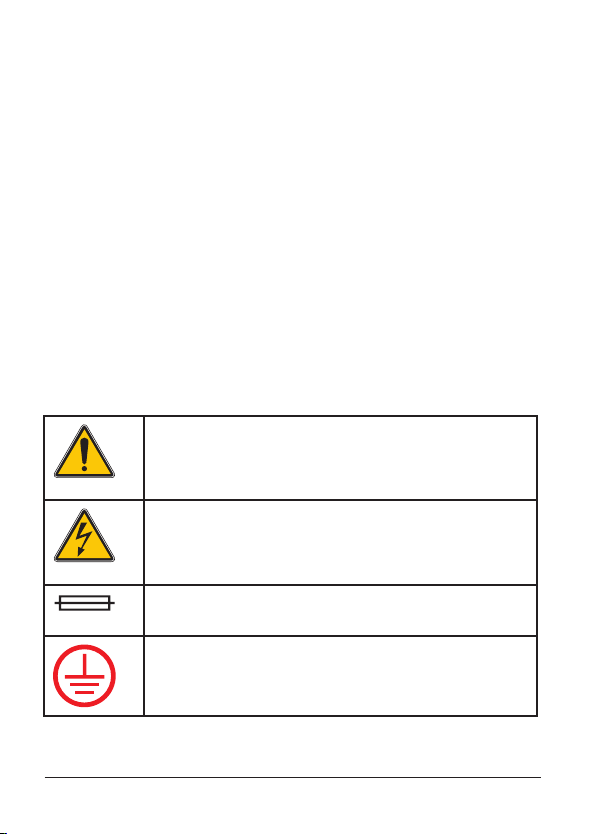
This symbol, if noted on the device, references the
instruction manual for operation and/or safety
information.
This symbol, when noted on a product enclosure or
barrier, indicates that a risk of electric shock and/or
electrocution exists.
This symbol, when noted on the product, identifies
the location of a fuse or current limiting device.
This symbol, when noted on the product, identifies
the location of the connection for Protective Earth
(ground).
6
Page 7
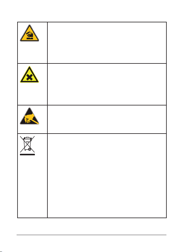
This symbol, when noted on the product, identifies
a risk of chemical harm and indicates that only individuals qualified and trained to work with chemicals
should handle chemicals or perform maintenance
on chemical delivery systems associated with the
equipment.
This symbol, when noted on the product, identifies
the presence of a noxious substance and a risk of
chemical harm. Only individuals qualified and
trained to work with chemicals should handle
chemicals or perform maintenance on chemical
delivery systems associated with the equipment.
This symbol, when noted on the product, indicates
the presence of devices sensitive to electrostatic
discharge (ESD) and indicates that care must be
taken to prevent damage with the equipment.
Electrical equipment marked with this symbol may
not be disposed of in European public disposal
systems after 12 August of 2005. In conformity with
European local and national regulations (EU Directive
2002/96/EC), European electrical equipment users
must now return old or end-of life equipment to the
Producer for disposal at no charge to the user.
Note:
You can obtain instructions on the correct disposal
of all (marked and unmarked) electrical products
that have been supplied or manufactured by HachLange from your local Hach-Lange sales office.
7
Page 8

Signal words for hazard information
This manual uses signal words to mark safety information.
They are used alone or in combination with a safety symbol.
If multiple hazards exist, this manual will use the signal word
(Danger, Caution, Note) corresponding to the greatest hazard.
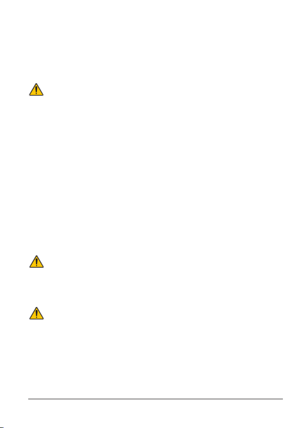
DANGER Indicates a potentially or imminently
hazardous situation which, if not avoided,
could result in death or serious injury.
CAUTION Indicates a potentially hazardous situation
that may result in minor or moderate
injury.
Important Note Information that requires special
emphasis.
Note Information that supplements points in
the main text.
8
Page 9
General safety information
Do not use or install the si794 transmitter in any manner other
than that which is specified in this manual.
Important Note
Commissioning must only be carried out by trained personnel.
Whenever it is likely that protection has been impaired, the device
shall be made inoperative and secured against unintended
operation.
The safety of the transmitter may be impaired if any of the
following conditions have occurred:
visible damage•
failure to operate properly•
storage above 70 °C for prolonged periods•
exposure to severe transport stresses•
If any of these conditions have occurred, return the device to the
manufacturer for recertification.
Note
Before commissioning it must be proved that the transmitter may
be connected with other equipment.
Important Note
Working with chemical samples, standards, reagents, and waste
presents potential hazards.
The device must only be operated by trained personnel authorized
by the operating company.
The manufacturer is not liable for any damages caused by processrelated risks known to the operating company.
9
Page 10

Information on how to prevent electrostatic discharges (ESD)
Important Note
The sensitive electronic components in the device can be damaged
by static electricity. This can impair device performance and even
lead to a complete failure of the device.
Before connecting a sensor, for example, you should discharge any
static electricity buildup from your body. To do so, you can touch an
earth-grounded metal surface such as the chassis of a device or a
metal conduit or pipe.
10
Page 11
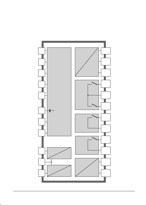
Overview of si794 P
Glass
electrode
Reference
electrode
Auxiliary
electrode
RTD
RTD
Shield
ISFET
+3V
ISFET
-3V
HOLD
HOLD/
CONTROL
CONTROL
1
pH / mV /
temp
input
2
3
E
Output 1
Output 2
R1
D
R2
9
10
11
12
13
14
+ Output 1
– Output 1/2
+ Output 2
Relay 1
Relay 1/2
Relay 2
C
± 3 V
4
for ISFET
sensor
Alarm
15
16
Alarm
Alarm
5
Clean / PSet 2
Clean
HOLD
6
input
7
Control
8
input
Power
17
18
19
20
Clean / PSet 2
Power
Power
11
Page 12
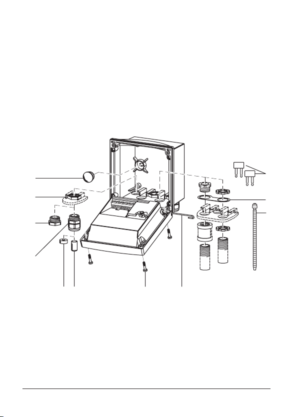
Assembly
11
10
9
8
76 5
4
1
2
3
Package contents
Check the shipment for transport damage and completeness.
The package should contain:
• Front unit
• Rear unit
• Bag containing small parts
• User manual
• Specific test report
1 Jumper (2 x)
2 Washer (1 x), for conduit
mounting: Place washer between
enclosure and nut
3 Cable tie (3 x)
4 Hinge pin (1 x), insertable from
either side
5 Enclosure screw (4 x)
Fig.: Assembling the enclosure
12
6 Sealing insert (1 x)
7 Rubber reducer (1 x)
8 Strain relief (3 x)
9 Filler plug (3 x)
10 Hex nut (5 x)
11 Sealing plug (2 x),
for sealing in case of wall mounting
Page 13
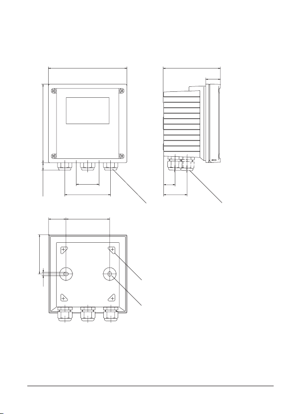
Mounting plan
144
144
15
42
84
80
32
21
43
105
27
72
6,2
12
3
4
Fig.: Mounting plan – All dimensions in mm!
1 Strain relief (3 x)
2 Strain relief or 1/2“ conduit
opening, ø 21.5 mm (2 x)
Conduit hardware not included!
3 Knockout for pipe mounting
(4 x )
4 Knockout for wall mounting
(2 x )
13
Page 14
40 60
132
1
2
3
4
5
1
132165
173
1
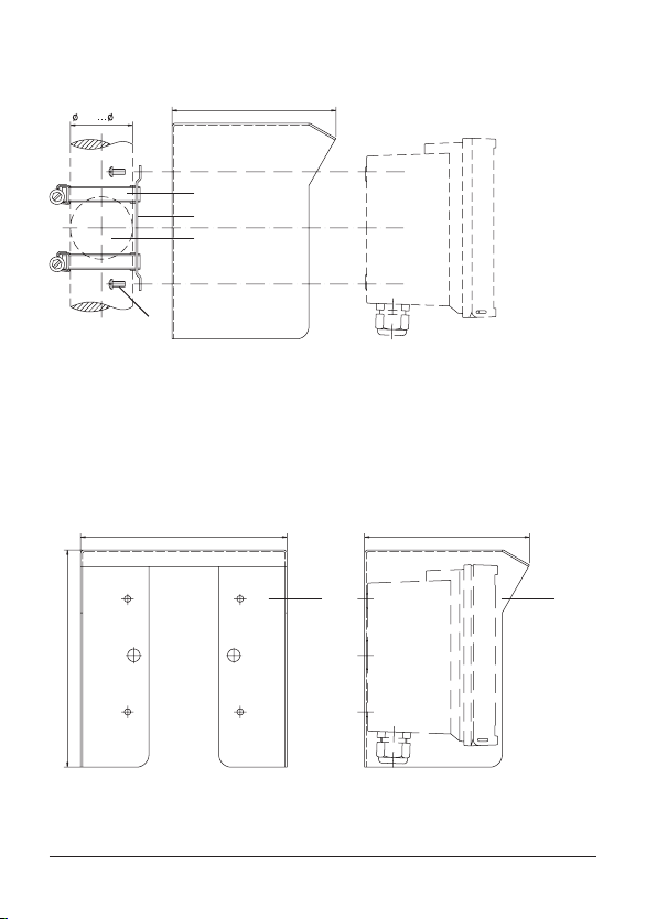
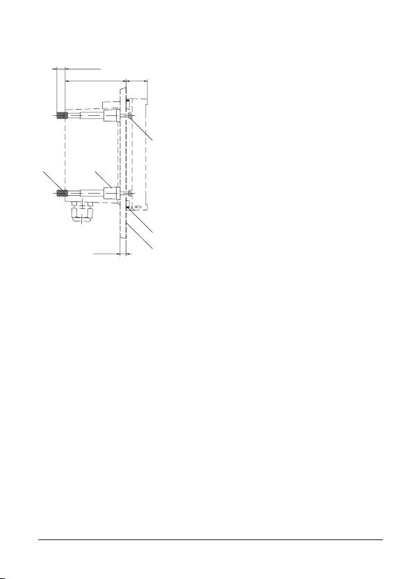
Pipe mounting, panel mounting
1 Protective hood (LZY485) - if required
2 Hose clamp with worm gear drive to DIN 3017 (2 x)
3 Pipe-mount plate (1 x)
4 For vertical or horizontal posts or pipes
5 Self-tapping screw (4 x)
Fig.: Bracket kit (LZY483) – All dimensions in mm!
Fig.: LZY485 protective hood for wall and pipe mounting
– All dimensions in mm!
14
Page 15
1
2
3
45
max. 25
78 27
1...22
1 Screw (4 x)
2 Gasket (1 x)
3 Control panel
4 Span piece (4 x)
5 Threaded sleeve (4 x)
Fig.: Panel mounting kit (LZY484) – All dimensions in mm!
15
Page 16
Installation and connection
Installation instructions
Caution!
Any work on the electrical installation may only be undertaken by
experienced and qualified personnel in accordance with the applicable
local safety regulations.
• Always disconnect power to the device when making any electrical
connections!
• Be sure to follow the instructions in the user manual!
• Only connect the power supply when all internal wirings have been
completed and the system is correctly grounded!
When using an external voltage supply, always connect a ground-fault
circuit interrupter (tripping current max. 30 mA) between mains and
controller system! A ground-fault circuit interrupter is not required
when safety extra-low voltages (24 V DC supply via rechargeable
batteries or 24 V DC/AC supply through an isolation transformer)!
When operating the system outdoors, connect a surge voltage
protection between mains and controller system!
The terminals are suitable for single wires and flexible leads up to
2.5 mm² (AWG 14). Attach end ferrules to the leads.
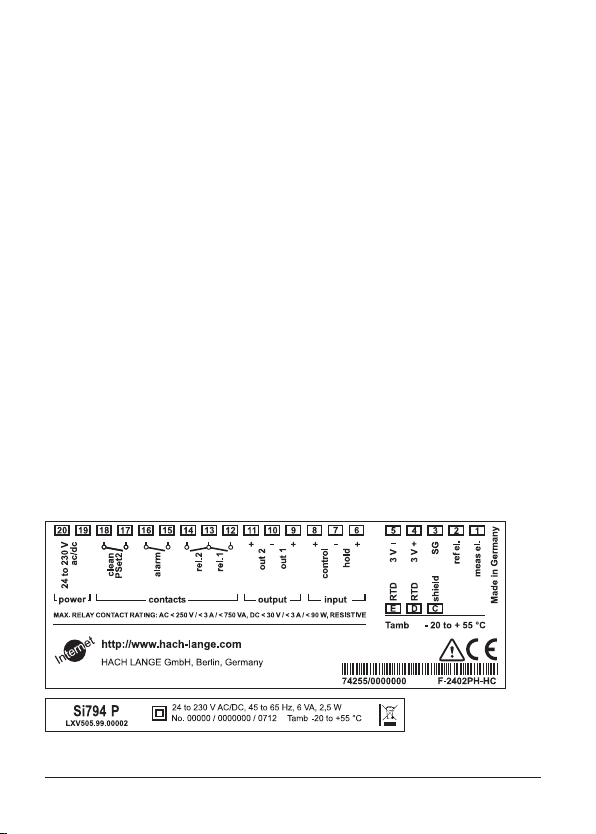
Terminal assignments
Danger of electric shock!
Fig.: si794 P terminal assignments
16
Page 17
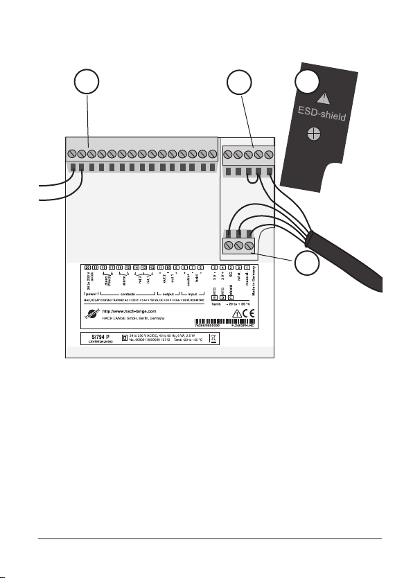
4
3
1 ESD shield covering the signal inputs
(Screw off for assembly)
Note:
The cable shield must end under the ESD shield.
(Cut lines if required)
2 Terminals for temperature probe and outer shield
3 Terminals for electrode
4 Power supply connection
1
2
Fig.: Information on installation, rear side of device
17
Page 18
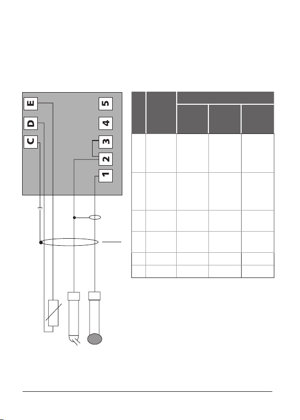
pH wiring examples
Example 1:
pH measurement with
monitoring of glass electrode
Jumper
across
2 and 3
Cable shield –
Do not ground!
Color
Top 68
Assign-
ment
Jumper
cable
Coax
core
Coax
(shield)
Terminal
1 Glass
electrode
2 Ref.
electrode
(
3
2-3)
C Shield Green/
D RTD Red Green Red
E RTD White White White
SMEK
cable
Transparent
(coax
core)
Black
(coax
shield)
yellow
8350.0
Transparent
(coax
core)
Black
(coax
shield)
18
Page 19
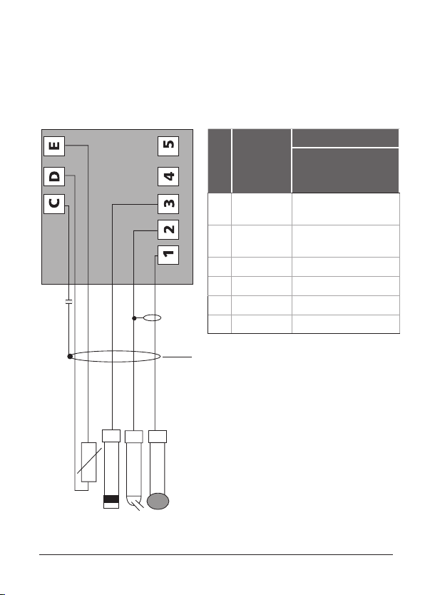
Example 2:
pH measurement with
monitoring of glass and
reference electrode
Terminal
Assign-
1 Glass
electrode
2 Reference
electrode
3 SG Blue
C Shield
D RTD Red
E RTD White
Cable shield –
Do not ground!
ment
Color
8350.3
8350.4
8350.5
Transparent
(coax core)
Black
(coax shield)
19
Page 20
1
2
3
1
2
3
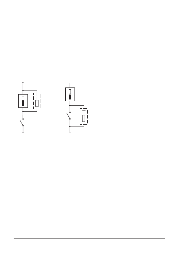
Protective wiring of relay outputs
Protective wiring of relay contacts
Relay contacts are subject to electrical erosion. Especially with
inductive and capacitive loads, the service life of the contacts will
be reduced. For suppression of sparks and arcing, components
such as RC combinations, nonlinear resistors, series resistors, and
diodes should be used.
Typical AC applications
with inductive load
1 Load
2 RC combination, e.g. RIFA PMR 209
Typical RC combinations
for 230 V AC:
Capacitor 0.1µF / 630V,
Resistor 100 ohms / 1 W
3 Contact
20
Page 21
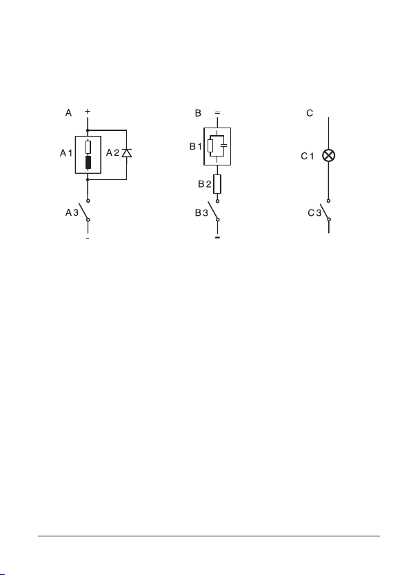
Typical protective wiring measures
A: DC application with inductive load
B: AC/DC applications with capacitive load
C: Connection of incandescent lamps
A1 Inductive load
A2 Free-wheeling diode, e.g. 1N4007 (Observe polarity)
A3 Contact
B1 Capacitive load
B2 Resistor, e.g. 8 Ω / 1 W at 24 V / 0.3 A
B3 Contact
C1 Incandescent lamp, max 60 W / 230 V, 30 W / 115 V
C3 Contact
Warning!
Make sure that the maximum ratings of the relay contacts are
not exceeded even during switching!
21
Page 22
Interface and navigation
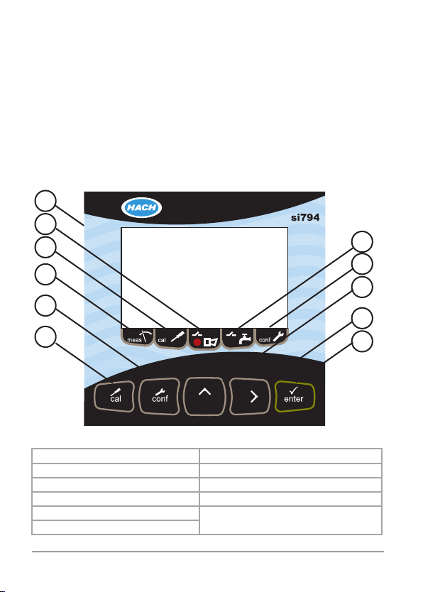
The si794 transmitter user interface contains a display, indicators,
and keys for navigation and menu selection.
User interface
Use the arrow and enter keys to scroll through the menu and
change settings. Use the indicators to identify which mode the
transmitter is in.
6
5
4
3
2
1
Fig.: si794 user interface
1 Calibration key 7 Wash mode indicator
2 Congure key 8 Conguration mode indicator
3 Measure mode indicator 9 Up arrow key
4 Calibration mode indicator 10 Right arrow key
5 Alarm indication
6 Display
11 Enter key
7
8
9
10
11
22
Page 23
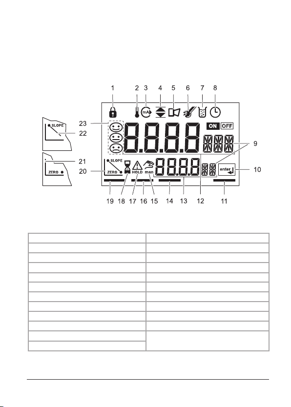
Display
Interface and navigation
4.3 Display
Figure 11 identifies all of the possible icons and symbols that may be
seen in the si792 transmitter display.
The gure below identies all of the possible icons and symbols
that may be seen in the si794 transmitter display.
Fig.: si794 display
1 Passcode 13 Secondary display
2 Temperature 14 Alarm mode
3 4–20 mA/HART output 15 Manual temperature on
4 Limit values 16 Calibration mode
5 Alarm 17 Hold mode active
6 Sensocheck: Sensor error 18 Hourglass (waiting indication)
7 Calibration active 19 Measure mode active
8 Calibration interval 20 Calibration complete
8 Parameter display 21 Calibration: zero or rst point
10 Enter prompt 22 Calibration: second point
11 Conguration mode
12 Main display
23 Sensofaces
23
Page 24
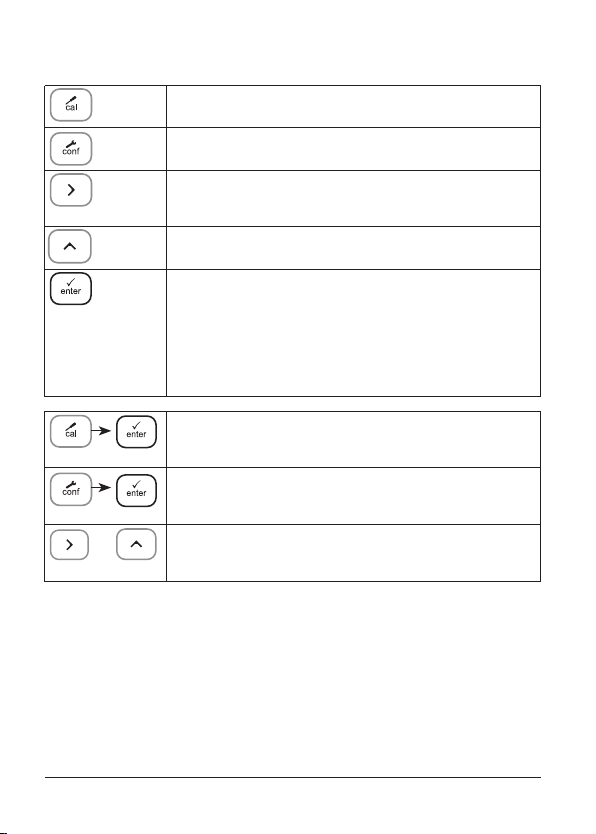
Operation: Keypad
Start, end calibration
Start, end configuration
Select digit position
(selected position blinks)
Edit digit
• Calibration:
Continue in program sequence
• Configuration: Confirm entries,
next configuration step
• Measuring mode: Display output current
Cal Info: Display of offset (zero point) and slope
Error Info: Display of last error message
24
+
Start GainCheck device self-test
Page 25

Safety functions
Sensocheck, Sensoface sensor monitoring
Sensocheck continuously monitors the sensor and its wiring.
Sensocheck can be switched o (Conguration).
Sensoface provides information on the electrode condition. The oset (zero point), slope, and response time
during calibration are evaluated. The three Sensoface
indicators provide the user with information about wear
and required maintenance of the electrode.
GainCheck device self-test
A display test is carried out, the software version is displayed,
and the memory and signal transfer are checked.
Start GainCheck device self-test:
Automatic device self-test
The automatic device self-test checks the memory and signal
transfer. It runs automatically in the background at xed intervals.
+
25
Page 26

Safety functions
Hold mode
Display:
The Hold mode is a safety state during conguration and calibration. Output current is frozen (Last) or set to a xed value (Fix).
Alarm and limit contacts are disabled.
If the calibration or conguration mode is exited, the transmitter
remains in the Hold mode for safety reasons. This prevents undesirable reactions of the connected peripherals due to incorrect
conguration or calibration. The measured value and “HOLD” are
displayed alternately. The transmitter only returns to measuring
mode after enter is pressed and 20 seconds have passed.
Conguration mode is also exited automatically 20 minutes
(timeout) after the last keystroke. The transmitter returns to
measuring mode.
Timeout is not active during calibration.
Response of output signal:
Last: The output current is frozen at its last value.
Recommended for short conguration procedures.
The process should not change decisively during conguration. Changes are not noticed with this setting!
Fix: The output current is set to a value that is noticeably
dierent from the process value in order to signal the
control system that the transmitter is being worked at.
26
Page 27
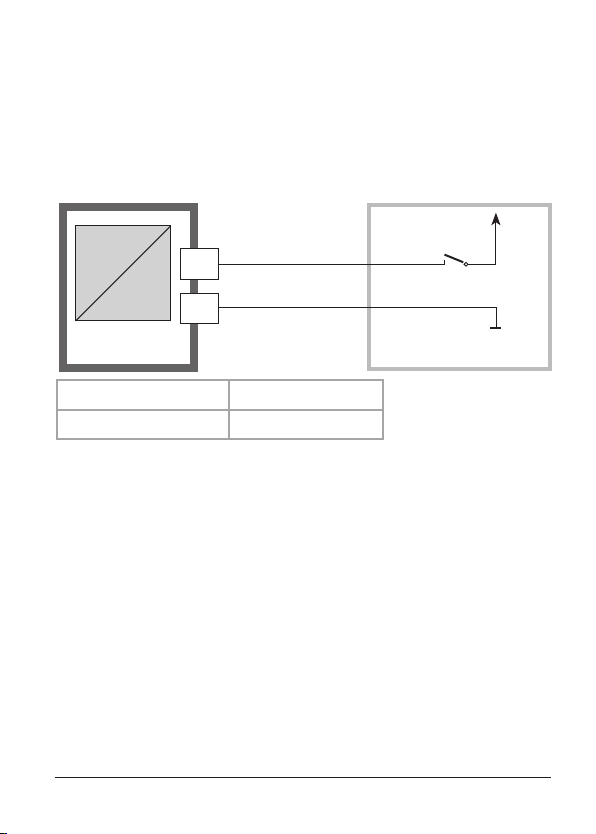
External activation of HOLD mode
The Hold mode can be activated from outside by sending a signal
to the Hold input (e.g. from the process control system).
Power supply
Hold
12...24 V AC/DC
6
input
si794
7
Process control system
Hold active Hold inactive
10 ... 30 V AC/DC 0 ... 2 V AC/DC
Alarm
The alarm delay is congurable.
During an error message the alarm LED blinks or lights.
Error messages can also be signaled by a 22 mA output current.
The alarm contact is activated by alarm or power failure,
see also Pg 50.
The alarm LED on the front panel can be congured as follows
HOLD o: Alarm: LED blinks
HOLD on: Alarm: LED on. HOLD: LED blinks
27
Page 28
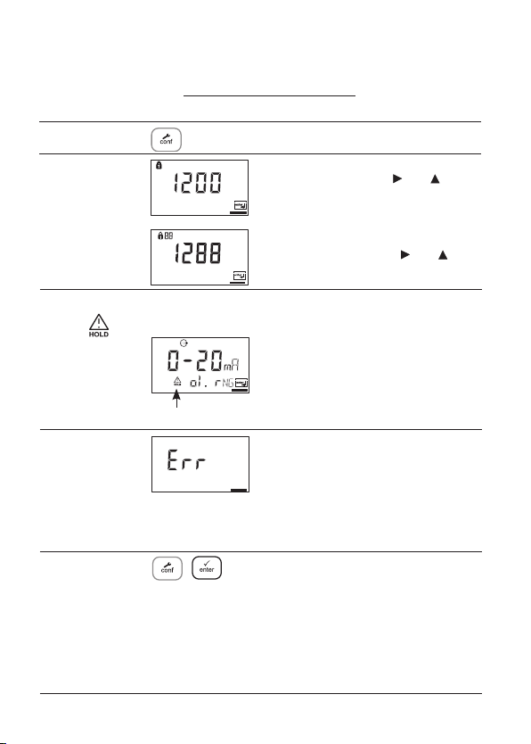
Configuration
In the Configuration mode you set the device parameters. The device can
store two different parameter sets and switch between them. Sensor data and
“Clean/Pset2” output are edited in parameter set 1 only. They are valid for
both parameter sets.
Configuring
Parameter set 1
Configure:
Press conf.
Enter mode code “1200”:
Edit parameter set 1 with and , confirm/proceed with enter.
Parameter set 2
Configure:
“88” appears in the
display.
Enter mode code “1288”:
Edit parameter set 2 with
firm/proceed with enter.
and , con-
The output current is frozen
Hold
During
configuration
the device
remains in the
Hold mode.
Input errors
HOLD icon
(at its last value or at a preset fixed
value, depending on the configuration), limit and alarm contacts are inactive. The controller is in the configured
state, Sensoface is off, mode indicator
“Configuration” is on.
The configuration parameters are
checked during the input. In the
case of an incorrect input “Err” is displayed for approx. 3 s. The incorrect
parameters cannot be stored. Input
must be repeated.
End End with conf. The measured value
and Hold are displayed alternately,
“enter” flashes. End Hold mode with
enter . The display shows the measured value. The output current remains
frozen for another 20 s (HOLD icon on,
“hourglass” flashes).
28
Page 29
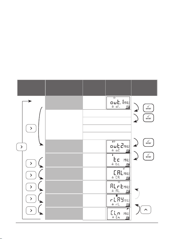
Menu structure of conguration
The conguration steps are assigned to dierent menu groups.
Use the arrow keys to jump between the individual menu
groups. Each menu group contains menu items for setting the
parameters.
Press enter to access a menu item. Use the arrow keys to edit
values. Press enter to conrm/save the settings.
To return to measurement, press conf and then enter.
Select menu
group
Menu group Code Display
Output 1 o1.
Menu item 1
Menu item 2
Menu item ...
Output 2 o2.
Temperature
compensation
Calibration mode CA.
Alarm settings AL.
Relay rL.
Cleaning contact
PSet 2 selection
tc.
Cn.
...
Select
menu item
Previous
menu
group:
29
Page 30

Overview of conguration steps
Code
Menu
Output 1
out1
o1.
Select process variable
Select electrode type
Select current range
Enter current start
Enter current end
Time averaging filter
22 mA signal in the case of error
Signal response during HOLD
Enter fixed value
Output 2
out2
o2.
Select temperature unit
Select temperature probe
Select current range
Enter current start
Enter current end
Time averaging filter
22 mA signal for temp error
Signal
response
Enter fixed value
Temperature compensation
tc.
tc.
Temp detection during meas
Temp detection during cal
Enter TC process medium
Calibration mode
CAL
CA.
Select calibration mode
Enter cal timer interval
during HOLD
Choices Default
PH/ORP PH
(GLAS EL/FEt EL ) GLAS EL
0-20 mA/4-20 mA 4-20 mA
xxxx 00.00 pH
xxxx 14.00 pH
xxxx SEC 0 SEC
ON / OFF OFF
Last / Fix Last
xxx.x mA 021.0 mA
°C / °F °C
100 Pt/1000 Pt/30NTC/
8.55NTC/3000B 1000 Pt
0-20 mA/4-20 mA 4-20 mA
xxx.x 000.0 °C
xxx.x 0100.0 °C
0000 ... 0120 SEC) 0 SEC
ON / OFF OFF
Last / Fix Last
xxx.x mA 021.0 mA
Auto/man (man: xxx.x °C)
Auto/man (man: xxx.x °C)
xx.xx %/K 00.00%/K
BUF/MAN/DAT 06 BUF
xxxx h 0000 h
30
Page 31

Code
Menu
Alarm settings
ALrt
AL.
Select Sensocheck
Enter alarm delay
LED in HOLD mode
Relay 1/2: Limit values, controller
rL AY
rL.
Select limit function / controller
Select contact function
L1.
Select contact response
Enter setpoint
Enter hysteresis
Enter delay
Select contact function
L2.
Select contact response
Enter setpoint
Enter hysteresis
Enter delay
Enter controller setpoint
Ct.
Enter neutral zone
(P) Controller gain K
(I) Reset time T
(D) Rate time T
Pulse length/frequency controller
PLC: Pulse length
PFC: Pulse frequency
Select HOLD response
Cleaning contact
Cln.
Cn.
Select cleaning contact or signaling
of parameter set 2
Cleaning interval
rinse
Cleaning duration
Select contact response
Choices Default
ON / OFF OFF
xxxx sec 0010 sec
ON / OFF OFF
LiMIT / CtROL LiMIT
Lo / Hi Lo
N/O / N/C N/O
xxxx 00.00 pH
xxxx 00.50 pH
xxxx SEC 0010 SEC
Lo / Hi Hi
N/O / N/C N/O
xxxx
xxxx 00.50 pH
xxxx SEC 0010 sec
xxxx 07.00 pH
xxxx 01.00 pH
xxxx % 0100 %
P
R
D
xxxx SEC 0000 SEC
xxxx SEC 0000 SEC
PLC / PFC PLC
xxxx SEC 0010 SEC
xxxx /min 0060 /min
Y Last / Y Off Y Last
rinse / Pset2 rinse
xxx.x h 000.0 h
xxxx SEC 0060 SEC
N/O / N/C N/O
14.00 pH
31
Page 32

Conguration
Output 1
Select type of electrode / Measurement procedure
Menu group
Output 1
Code
o1.
Display
Select menu item
Select process variable
Select electrode type
Select 0-20 / 4-20 mA
Enter current start
Enter current end
Set output filter
22 mA for error
HOLD mode
Exit:
Press conf, then enter.
32
Page 33

Code Display
o1.
After correct input a
welcome text (CONF) is
displayed for approx. 3 sec
Action
Select configuration
(Press conf.)
Enter passcode “1200”
(Use to select the position, use
to edit the number. When the
display reads “1200”, press enter
to confirm.)
The transmitter goes to HOLD
mode. (HOLD icon is active, red
LED blinks when “HOLD ON” has
been configured.)
Choices
Select parameter pH/ORP
Select using key
Press enter to proceed
Only with pH selected:
Select electrode type:
• Glass electrode
• ISFET electrode
Select using key
Press enter to proceed
Note: Characters represented in gray are blinking and can be edited.
pH/ORP
Glass
(FEt EL)
33
Page 34

Conguration
Output 1
Output current range / Current start / Current end
Menu group
Output 1
Code
o1.
Display
Select menu item
Select process variable
Select electrode type
Select 0-20 / 4-20 mA
Enter current start
Enter current end
Set output filter
22 mA for error
HOLD mode
34
Exit:
Press conf, then enter.
Page 35

Code
o1.
Display
Action
Set output current range
Select using key
Press enter to proceed
Choices
4 - 20 mA
(0 - 20 mA)
Current start
Enter lower end of scale,
depending on the process
variable selected (pH or ORP)
Select using , edit number
using . Press enter to proceed.
Current end
Enter upper end of scale,
depending on the process
variable selected (pH or ORP)
Select using , edit number
using . Press enter to proceed.
Assignment of measured values:
Current start and current end
Example 1: Range pH 0 ... 14 Example 2: Range pH 5 ... 7 .
[pH]
14
0
Output current
20 4
Advantage: Higher resolution in
[mA]
range of interest
[pH]
7
5
Output current
pH -2 ... 16
(-1500 mV
...
+1500mV)
pH -2 ... 16
(-1500 mV
...
+1500mV)
20 4
[mA]
35
Page 36

Conguration
Output 1
Time averaging lter
Menu group
Output 1
Code
o1.
Display
Select menu item
Select process variable
Select electrode type
Select 0-20 / 4-20 mA
Enter current start
Enter current end
Set output filter
22 mA for error
HOLD mode
Exit:
Press conf, then enter.
36
Page 37

Display Action
Code
o1.
Time interval of output filter
Default setting: 0 sec (inactive).
To specify a time interval:
Select position using ,
edit number using .
Press enter to proceed.
Choices
0 sec
0...120 sec
Time averaging filter
To smoothen the current output, a low-pass filter with adjustable
filter time can be switched on. When there is a jump at the input
(100 %), the output level is at 63 % after the time interval has been
reached.
The time interval can be set from 0 to 120 sec.
If the time interval is set to 0 sec, the current output follows the
input.
Note:
The filter only acts on the current output, not on the display, the
limit values, or the controller!
Time interval 0 to 120 sec
37
Page 38

Conguration
Output 1
Output current during Error and HOLD
Menu group
Output 1
Code
o1.
Display
Select menu item
Select process variable
Select electrode type
Select 0-20 / 4-20 mA
Enter current start
Enter current end
Set output filter
22 mA for error
HOLD mode
Exit:
Press conf, then enter.
38
Page 39

Code
o1.
Display
Action
22 mA signal for error message
Select using key
Press enter to proceed
Choices
OFF
(ON)
Output signal during HOLD
LAST: During HOLD the last
measured value is maintained at
the output
FIX: During HOLD a value (to be
entered) is maintained at the
output
Select using key
Press enter to proceed
Only with FIX selected:
Enter current which is to flow at
the output during HOLD
Select position using key and
edit number using key.
Press enter to proceed
Output signal during HOLD:
Output current
[mA]
21
4
Output signal for HOLD
FIX setting = 21.0 mA
HOLD active
LAST
(FIX)
21.0 mA
(00.0 ...
21.0 mA)
Output signal for HOLD
LAST setting
HOLD active
39
Page 40

Conguration
Output 2
Temperature unit and probe / Output current
Menu group
Output 2
Code
o2.
Display
Select menu item
Select °C/°F
Select temperature probe
Select 0-20 / 4-20 mA
Enter current start
Enter current end
Set output filter
22 mA for temp error
HOLD mode
Exit:
Press conf, then enter.
40
Page 41

Code
o2.
Display
Action
Specify temperature unit
Select using key
Press enter to proceed
Select temperature probe
Select using key
Press enter to proceed
Set output current range
Select using key
Press enter to proceed
Choices
°C
(°F)
1000 PT
(100 PT,
30NTC,
8.55NTC,
3000B)
4 - 20 mA
(0 - 20 mA)
Current start:
Enter lower end of scale.
Select using , edit number
using. Press enter to proceed.
Current end:
Enter upper end of scale.
Select using , edit number
using. Press enter to proceed.
Process temperature: Current start and current end
Example 1: Range 0 ... 100 °C Example 2: Range 50 ... 70 °C
[°C]
Process temperature
100
0
Output current
20 4
Advantage: Higher resolution in
[mA]
range of interest
Process temperature
[°C]
70
50
000.0 °C
100.0 °C
Output current
20 4
[mA]
41
Page 42

Conguration
Output 2
Time averaging lter
Menu group
Output 2
Code
o2.
Display
Select menu item
Select °C/°F
Select temperature probe
Select 0-20 / 4-20 mA
Enter current start
Enter current end
Set output filter
22 mA for temp error
HOLD mode
Exit:
Press conf, then enter.
42
Page 43

Code
o2.
Display
Action
Time averaging filter
Default setting: 0 sec (inactive).
To specify a time constant: Select
using , edit number using.
Press enter to proceed.
Choices
0 sec
(0...120 sec)
Time averaging filter
To smoothen the current output 2, a low-pass filter with adjustable
filter time can be switched on. When there is a jump at the input
(100 %), the output level is at 63 % after the time interval has been
reached.
The time interval can be set from 0 to 120 sec.
If the time interval is set to 0 sec, the current output follows the
input.
Note:
The filter only acts on the current output, not on the display, the
limit values, or the controller!
Time interval 0 to 120 sec
43
Page 44

Conguration
Output 2
Temperature error / Output current during HOLD
Menu group
Output 2
Code
o2.
Display
Select menu item
Select °C/°F
Select temperature probe
Select 0-20 / 4-20 mA
Enter current start
Enter current end
Set output filter
22 mA for temp error
HOLD mode
Exit:
Press conf, then enter.
44
Page 45

Code
o2.
Display
Action
22 mA signal for error message
Select using key
Press enter to proceed
Choices
OFF
(ON)
Output signal during HOLD
LAST: During HOLD the last
measured value is maintained at
the output
FIX: During HOLD a value (to be
entered) is maintained at the
output
Select using key
Press enter to proceed
Only with FIX selected:
Enter current which is to flow at
the output during HOLD
Select position using key and
edit number using key.
Press enter to proceed
Output signal during HOLD:
Output current
[mA]
21
4
Output signal for HOLD
FIX setting = 21.0 mA
HOLD active
LAST
(FIX)
21.0 mA
(00.0 ...
21.0 mA)
Output signal for HOLD
LAST setting
HOLD active
45
Page 46

Conguration
Temperature compensation
Temp detection for meas/cal / TC process medium
Menu group
Temperature
compensation
Code
tc.
Display
Select menu item
Temp during meas.
Temp during calibration
TC of process medium
46
Exit:
Press conf, then enter.
Page 47

Code
tc.
Display
Action
Select temp detection during
measurement (Auto/MAN)
AUTO: Temp detection with
temperature probe
MAN: Manual temperature input
Select using key,
press enter to proceed
Choices
AUT
(MAN)
Only with manual temp detection
selected (MAN)
Enter temperature.
Select position using key,
edit number using key.
Press enter to proceed
Select temp detection during
calibration (Auto/MAN)
Select using key,
press enter to proceed
Only with manual temp detection
selected (MAN)
Enter temperature.
Select position using key,
edit number using key.
Press enter to proceed
For pH measurement only:
Enter temperature compensation
of process medium
Select position using key,
edit number using key.
Press enter to proceed
25.0 °C
(xxx.x °C)
AUT
(MAN)
25.0 °C
(xxx.x °C)
00.00 %/K
(-19.99 ...
19.99 %/K)
47
Page 48

Conguration
Calibration mode
Menu group
Calibration mode
Code
CA.
Display
Select menu item
Calibration mode
Cal timer interval
Exit:
Press conf, then enter.
48
Page 49

Code
CA.
Display
Action
For pH measurement only:
Select calibration mode
BUF: Calibration with Calimatic
automatic buffer selection.
To do so, you must select your
buffer set:
-01- BUF: Mettler-Toledo
-02-BUF: Merck Titrisols, Riedel Fixanals
-03- BUF: Ciba (94)
-04-BUF: NIST technical buffers
-05-BUF: NIST standard buffers
-06-BUF: HACH buffers
-07-BUF: WTW technical buffers
-08- BUF: Hamilton Duracal
MAN: Calibration with
Manual Buffer Entry
DAT: Entry of offset and slope of
premeasured electrodes
Select using key,
proceed.
press enter to
Choices
-01-BUF
(-02-BUF/
-03-BUF/
-04-BUF/
-05-BUF/
-06-BUF/
-07-BUF/
-08-BUF/
MAN/
DAT )
Enter calibration interval:
Entry of time interval within
which the transmitter is to be
calibrated.
With a time interval of 0000 hrs
the calibration timer is not active.
Select using , edit number
using.
Press enter to proceed.
0000 h
(0000 ...
9999 h)
49
Page 50

Conguration
Alarm settings
Menu group
Alarm settings
Alarm
Code
AL.
Display
Select menu item
Select Sensocheck
Delay
LED in HOLD mode
Exit:
Press conf, then enter.
Alarm contact
15
The alarm contact is closed during normal operation (N/C).
It opens in the case of alarm or power outage. As a result,
16
a failure message is provided even in the case of line
breakage (fail-safe behavior). For contact ratings, see
Specifications.
Error messages can also be signaled by a 22 mA output
current.
The operating behavior of the alarm contact is shown on
Pg 91.
The alarm delay acts on the LED, the 22 mA signal, and
the alarm contact.
50
Page 51

Code
Display
Action
Choices
AL.
Select Sensocheck
(continuous monitoring of glass
and reference electrode)
Select using
press enter to proceed.
Alarm delay
Select using, edit number
using
LED in Hold mode
Select using key,
press enter to proceed.
LED state:
Setting
ON
OFF
key,
. Press
enter to proceed.
Alarm HOLD
on blinks
blinks off
ON/OFF
0010 sec
(xxxx sec)
ON/OFF
51
Page 52

Conguration
Limit function
Relay 1
Menu group
Relay / Controller
Code
rL.
Display
Select menu item
Contact function
L1.
Contact response
Enter setpoint
Enter hysteresis
Delay
L2.
Relay 2 menu group
Controller menu group
Ct.
Exit:
Press conf, then enter.
52
Page 53

Code
rL.
Display
Action
Use of relays:
• Limit function (LiMIT )
• Controller (CtROL)
Select using
Press enter to proceed.
Note: Selecting CtROL leads to
Ct. controller menu group.
.
Choices
LiMIT
(CtROL)
L1.
For limit 1 function principle,
see page 55. Select using
Press enter to proceed.
Limit 1 contact response
N/C: normally closed contact
N/O: normally open contact
Select using .
Press enter to proceed
Limit 1 setpoint
Select using , edit number
. Press enter to proceed.
using
Limit 1 hysteresis
Select using , edit number
. Press enter to proceed.
using
Limit 1 delay
The contact is activated with
delay (deactivated without delay)
Select using
using
, edit number
. Press enter to proceed.
.
Lo
(Hi)
N/C
(N/O)
00.00 pH
(
xx.xx pH)
00.50 pH
(
xx.xx pH)
0010 sec
(
0 ... 9999
sec)
53
Page 54

Configuration
Limit function
Relay 2
Menu group
Relay / Controller
Code
rL.
Display
Select menu item
Relay 1 menu group
L1.
Contact function
L2.
Contact response
Enter setpoint
Enter hysteresis
Delay
Controller menu group
Ct.
Exit:
Press conf, then enter.
54
Page 55

Code
Display Action
Choices
L2.
Limit Lo
Hysteresis +
Setpoint
Contact
For limit 2 function principle,
see Fig. below. Select using
.
Hi
(Lo)
Press enter to proceed.
Limit 2 contact response
N/C: normally closed contact
N/C
(N/O)
N/O: normally open contact
Select using .
Press enter to proceed.
Limit 2 setpoint
Select using
using
, edit number
. Press enter to proceed.
Limit 2 hysteresis
Select using
. Press enter to proceed.
using
, edit number
Limit 2 delay
The contact is activated with
delay (deactivated without delay)
Select using
using
Signal
1
0
, edit number
. Press enter to proceed.
Limit Hi
Setpoint
Hysteresis -
1
Contact
0
14.00 pH
(
xx.xx pH)
00.50 pH
(
xx.xx %)
0010 sec
(
0 ...
9999 sec)
Signal
55
Page 56

Conguration
Controller (For description see Pg 84 and the following)
Setpoint / Neutral zone
Menu group
Relay / Controller
Code
rL.
Display
Select menu item
Relay 1 menu group
L1.
Relay 2 menu group
L2.
Ct.
Controller setpoint
Enter neutral zone
(P) Controller gain
(I) Reset time TR
(D) Rate time TD
Pulse length / Pulse
frequency controller
PLC: Pulse length
PFC: Pulse frequency
HOLD response
Exit:
Press conf, then enter.
56
Page 57

Code
Ct.
Display
Action
Setpoint
Select using , edit number
. Press enter to proceed.
using
Neutral zone (dead band)
Select using , edit number
. Press enter to proceed.
using
Controller: P action
Select using , edit number
. Press enter to proceed.
using
Choices
07.00 pH
(xx.xx pH)
01.00 pH
(xx.xx pH)
0100 %
(xxxx %)
Controller: I action (reset time)
Select using , edit number
. Press enter to proceed.
using
Controller: D action (rate time)
Select using , edit number
. Press enter to proceed.
using
Pulse length / Pulse frequency
Select using
Press enter to proceed.
PLC: Pulse length
Select using , edit number
using
PFC: Pulse frequency
Select using , edit number
using
Behavior during HOLD
Select using .
Press enter to proceed.
.
. Press enter to proceed.
. Press enter to proceed.
0000 sec
(xxxx sec)
0000 sec
(xxxx sec)
PLC
(PFC)
0010 sec
(xxxx sec)
0060/min
(xxxx /min)
Y Last
(Y Off)
57
Page 58

Configuration
Controlling a rinsing probe or
Signaling parameter set 1/2
Menu group
Contact:
CLEAN / PSet2
Code
Display
Cn.
rinse
58
Code
Cn.
Display
Select menu item
Select CLEAN / PSet2
Rinsing interval
Rinse time
Contact response
Action (rinsing probe)
Function selection*:
• Control of rinsing probe (rinse)
Signaling active parameter set 2
•
Select using ,
proceed.
Rinsing interval *
Select using , edit number
, press enter to proceed.
using
Rinse duration *
Select using , edit number
, press enter to proceed.
using
Select contact response*
N/O: normally open contact
N/C: normally closed contact
Select using ,
proceed
*) These parameters are only edited in parameter set 1.
They are valid for both parameter sets.
press enter to
press enter to
Choices
rinse
(rinse /
PSet2)
For
PSet2
see next
page
000.0 h
(xxx.x h)
0060 sec
(xxxx sec)
N/O
(
N/O
N/C)
:
Page 59

Controlling a rinsing probe
The “Clean” contact can be used to connect a simple rinsing probe.
Rinse duration and rinsing interval are defined during configuration.
Contact response can be set as N/O or N/C.
e.g. spray cleaning
Clean
17
18
Signaling parameter set 1/2
Depending on the selected parameter set, the relay is
active or inactive. The signal can be used for superordinated process control systems.
Parameter set 2 is indicated by “88” in the upper left
corner of the display.
Clean
PSet2
17
18
si794
Parameter set 1 selected
Parameter set 2 selected
Power supply
Power supply
Process control system
Power supply:
AC< 250 V / < 3 A / < 750 VA
DC< 30 V / < 3 A / < 90 W
59
Page 60

Selecting parameter set 1/2
Manually or via a signal at the Control input
Display
After correct input a
welcome text (CONF) is
displayed for approx. 3 sec
Action Choices
To select a parameter set, press conf,
enter code: 7654
Select position using , edit number
using ,
Wrong settings change the measurement
properties! If an invalid code is entered, the
transmitter returns to measuring mode.
press enter to proceed.
Select:
• Parameter set 1 (MAN)
• Parameter set 2 (MAN)
• Automatic switchover via
control input (Ctr-EXT)
Select using ,
With -1- or -2- selected:
Since the complete device configuration is changed in one step, there is a
security prompt (No/Yes).
Note:
When pressing enter directly,
the selection is not stored.
Activation of parameter set 2 is
indicated by “88” in the upper left
corner of the display.
press enter to proceed.
-1-
(-1- MAN
-2-MAN
Ctr-EXT)
For Ctr-EXT,
see next
page
60
Page 61

Display
Action Choices
With Control input
You can switch between the parameter
sets by applying an external signal to
the Control input (see below).
Ctr-EXT selected:
External switchover of parameter sets
The parameter set can be selected from outside by sending a
signal to the Control input (e.g. from the process control system).
To do so, Ctr-EXT is set during configuration.
Control
Power supply
7
input
si794
Note:
Parameter set 2 is indicated by “88” in the upper left corner of the
display.
8
Process control system
0 ... 2 V AC/DC Parameter set 1 selected
10 ... 30 V AC/DC Parameter set 2 selected
61
Page 62

62
Page 63

Default settings of parameter sets
Two complete parameter sets are stored in the EEPROM.
As delivered, the two sets are identical but can be edited.
Note:
Fill in your configuration data on the following pages.
Code. Parameter Default setting
o1. pH/ORP unit pH
o1. Electrode type GLASS
o1. 0/4-20 mA 4-20 mA
o1. Current start 00.00 pH
o1. Current end 14.00 pH
o1. Filter time 0 s
o1. 22mA signal OFF
o1. HOLD response Last
o1. Fix current 021.0 mA
o2. Unit °C / °F °C
o2. Temp probe 1000 PT
o2. 0/4 ...20mA 4-20 mA
o2. Current start 000.0 °C
o2. Current end 100.0 °C
o2. Filter time 0 s
o2. 22mA signal OFF
o2. HOLD response Last
o2. Fix current 021.0 mA
tc. TC measurement Auto
tc. Measuring temp 025.0 °C
tc. TC calibration Auto
tc. Calibration temp 025.0 °C
tc. TC medium 00.00 %/K
CA. Cal solution -06-BUF
CA. Cal interval 0000 h
AL. Sensocheck OFF
AL. Alarm delay 0010 sec
AL. LED Hold OFF
Code. Parameter Default setting
rL. Relay function Limit
L1. Contact function Lo
L1. Contact response N/C
L1. Setpoint 00.00 pH
L1. Hysteresis 00.50 pH
L1. Delay 0010 sec
L2. Contact function H i
L2. Contact response N/C
L2. Setpoint 14.00 pH
L2. Hysteresis 00.50 pH
L2. Delay 0010 sec
Ct. Setpoint 07.00 pH
Ct. Neutral zone 01.00 pH
Ct. P action 0100 %
Ct. I action 0000 sec
Ct. D action 0000 sec
Ct. PLC/PFC controller PLC
Ct. Pulse length 0010 sec
Ct. Pulse frequency 0060 /min
Ct. Hold response Last
Cn. Rinse/Par.set 2 Rinse
Cn. Rinsing interval 000.0 h
Cn. Rinse duration 0060 sec
Cn. Contact type N/C
63
Page 64

Parameter set, individual settings
Code. Parameter Setting
o1. pH/ORP unit ____________ ____________
o1. Electrode type ____________ ____________
o1. 0/4-20 mA ____________ ____________
o1. Current start ____________ ____________
o1. Current end ____________ ____________
o1. Filter time ____________ ____________
o1. 22mA signal ____________ ____________
o1. HOLD response ____________ ____________
o1. Fix current ____________ ____________
o2. Unit °C / °F ____________ ____________
o2. Temp probe ____________ ____________
o2. 0/4 ...20mA ____________ ____________
o2. Current start ____________ ____________
o2. Current end ____________ ____________
o2. Filter time ____________ ____________
o2. 22mA signal ____________ ____________
o2. HOLD response ____________ ____________
o2. Fix current ____________ ____________
tc. TC measurement ____________ ____________
tc. Measuring temp ____________ ____________
tc. TC calibration ____________ ____________
tc. TC medium ____________ ____________
CA. Cal solution ____________ ____________
CA. Cal interval ____________ ____________
AL. Sensocheck ____________ ____________
AL. Alarm delay ____________ ____________
AL. LED Hold ____________ ____________
64
Page 65

Code Parameter Setting
rL. Relay function ____________ ____________
L1. Contact function ____________ ____________
L1. Contact response ____________ ____________
L1. Setpoint ____________ ____________
L1. Hysteresis ____________ ____________
L1. Delay ____________ ____________
L2. Contact function ____________ ____________
L2. Contact response ____________ ____________
L2. Setpoint ____________ ____________
L2. Hysteresis ____________ ____________
L2. Delay ____________ ____________
Ct. Setpoint ____________ ____________
Ct. Neutral zone ____________ ____________
Ct. P action ____________ ____________
Ct. I action ____________ ____________
Ct. D action ____________ ____________
Ct. PLC/PFC controller ____________ ____________
Ct. Pulse length ____________ ____________
Ct. Pulse frequency ____________ ____________
Ct. Hold response ____________ ____________
Cn. Rinse /Par.set2 ____________ ____________
Cn. Rinsing interval ____________ ____________
Cn. Rinse duration ____________ ____________
Cn. Contact type ____________ ____________
65
Page 66

Calibration
Calibration adjusts the transmitter to the electrode.
Activation Activate with cal
Enter passcode.
Use and to edit a
parameter.
Press enter to conrm/continue.
(To exit, press cal, then enter.)
HOLD
During calibration the
transmitter
remains in
the Hold
mode.
HOLD icon
Input errors
Exit
During calibration the transmitter remains in the Hold mode
for reasons of safety. Output
current is frozen (last value or
preset xed value, depending
on conguration), limit and
alarm contacts are inactive. The
controller is in the congured
state, Sensoface is o, “Calibration” mode indicator is on. The
red LED blinks when “HOLD ON”
has been set.
The calibration parameters are
checked during the input. In the
case of an incorrect input “Err” is
displayed for approx. 3 sec. The
incorrect parameters cannot be
saved. Input must be repeated.
Press cal to exit. The measured
value is shown in the main
display alternately with “Hold”,
“enter” blinks, Sensoface is
active. Press enter key to end
the Hold mode. The measured
value is displayed. The output
current remains frozen for
another 20 sec (HOLD icon on,
“hourglass” blinks).
66
Page 67

pH calibration
Calibration is used to adapt the transmitter to the individual
electrode characteristics, namely oset and slope. Calibration
can be performed with Calimatic automatic buer recognition,
with manual buer input, by entering premeasured electrode
data, or by sampling the product.
When using ISFET sensors, you must adjust the zero point rst.
Then you can conduct either a one or a two-point calibration.
Caution
All calibration procedures must be performed by trained
•
personnel. Incorrectly set parameters may go unnoticed, but
change the measuring properties.
•
The response time of the electrode and temperature probe is
considerably reduced when the electrode is rst moved about
in the buer solution and then held still.
• The transmitter can only operate properly when the buer
solutions used correspond to the congured set. Other buffer solutions, even those with the same nominal values, may
demonstrate a dierent temperature response.
This leads to measurement errors.
When using ISFET sensors or electrodes with a zero point
other than pH 7, the nominal zero point must be adjusted each
time a new electrode is connected. This is important if you want
to obtain reliable Sensoface messages. The Sensoface messages
issued during all further calibrations are based on this basic
calibration.
67
Page 68

Zero adjustment (ISFET)
Allows use of electrodes with diering nominal zero (pH only)
Display
Action
Press cal, enter code: 1001
Select position using ,
edit number using ,
press enter to proceed.
Ready for calibration
“CAL” and “enter” are blinking.
Immerse electrode in a
pH 7.00 buffer. Enter the
perature-corrected pH value in
the range 6.50 to 7.50 using the
arrow keys (see buffer table).
Press enter to confirm.
Stability check.
The measured value [mV] is
displayed.
The “hourglass” icon is blinking.
tem-
Remark
The transmitter is in
the Hold mode.
If an invalid code is
entered, the
transmitter returns
to measuring mode.
Display (3 sec)
If the zero offset of
the electrode is too
large (> ± 200 mV ),
the CAL ERR error
message is generated. In that case the
electrode cannot be
calibrated.
Note:
Stability check can
be stopped (by
pressing cal).
However, this
reduces calibration
accuracy.
68
Page 69

Display
Action
At the end of the adjustment
procedure the zero offset [mV]
of the electrode is displayed
(based on 25 °C).
Press enter to proceed.
Remark
This is not the final
calibration value of
the electrode! Zero
point and slope must
be determined using
a complete 2-point
calibration (cal 1100)
(see following pages).
Confirmation prompt.
Display of pH value (alternately
with Hold) and temperature,
“enter” blinks, Sensoface is
active.
Place electrode in process.
Press enter to end zero
calibration.
After end of calibration, the outputs
remain in Hold
mode for approx.
20 sec.
Note for zero adjustment
After having adjusted the nominal zero point, be sure to calibrate
the electrode following one of the procedures as described on
the next pages:
• Automatic calibration with Calimatic
• Manual calibration
• Data entry of premeasured electrodes
69
Page 70

Automatic calibration with Calimatic (BUF -xx-)
Automatic or manual temperature detection
The transmitter can only operate properly when the buffer solutions used
correspond to the configured set. Other buffer solutions, even those with
the same nominal values, may demonstrate a different temperature
response. This leads to measurement errors.
Display
70
Action
Press cal, enter code: 1100
Select position using ,
edit number using
press enter to proceed.
Remove the electrode and
temperature probe, clean them,
and immerse them in the first
buffer solution (in any order).
When “Manual temp detection”
has been configured, enter the
value in the secondary display
using the arrow keys.
Press enter to start.
Buffer recognition
While the “hourglass” icon is
blinking, the electrode and
temperature probe remain in
the first buffer solution.
Buffer recognition terminated,
the nominal buffer value is
displayed.
,
Remark
If an invalid code is
entered, the transmitter returns to
measuring mode.
Transmitter in Hold
mode, measured
value frozen.
Sensoface inactive.
The response time
of the electrode
and temperature
probe is considerably reduced when
the electrode is
first moved about
in the buffer solution and then held
still.
Page 71

Display Action
Stability check:
The measured mV value is
displayed.
Calibration with the first buffer
is terminated. Remove the
electrode and temp probe
from the first buffer solution
and rinse them thoroughly.
Remark
To abort stability
check: Press cal.
(accuracy reduced)
• One-point calibration:
Press cal to end the calibration.
Slope [%] and offset [mV ] of
the electrode are displayed.
Press enter to proceed.
• Two-point calibration:
Immerse sensor and temperature probe in the second buffer
solution.
enter to start.
Press
Retract electrode and temp
probe out of second buffer,
rinse off, re-install.
Repeat calibration: cal
End calibration:
pH value and “Hold” are
displayed alternately. Sensoface
is active, “enter” blinks.
Press
enter
Hold is deactivated after 20 sec.
enter
to proceed.
For one-point
calibration only:
The calibration process runs again as
for the first buffer.
Slope and offset of
electrode (related to
25 °C) are displayed.
Confirmation
prompt.
71
Page 72

Manual Calibration
Automatic or manual temperature detection
For calibration with manual buer specication, you must enter the pH
value of the buer solution used in the transmitter for the proper temperature. This presetting enables calibration with any desired buer solution.
The MAN calibration mode and the type of temperature detection are
selected in the conguration mode.
Display
72
Action
Press cal, enter code: 1100
Select position using ,
edit number using ,
press enter to proceed.
Remove the electrode and
temperature probe, clean them
and immerse them in the first
buffer solution (in any order).
When “Manual temp detection”
has been configured, enter the
value in the secondary display
using the arrow keys.
Press enter to start.
Enter the pH value of your
buffer solution for the proper
temperature. While the “hourglass” icon is blinking, the electrode and temperature probe
remain in the buffer solution.
Remark
If an invalid code is
entered, the transmitter returns to
measuring mode.
Transmitter in Hold
mode, measured
value frozen.
Sensoface inactive.
The response time
of the electrode
and temperature
probe is considerably reduced when
the electrode is
first moved about
in the buffer solution and then held
still.
Page 73

Display Action
Stability check:
The measured mV value is
displayed.
Calibration with the first buffer
is terminated. Remove the
electrode and temp probe
from the first buffer solution
and rinse them thoroughly.
Remark
To abort stability
check: Press cal.
(accuracy reduced)
• One-point calibration:
Press cal to end the calibration.
Slope [%] and offset [mV ] of
the electrode are displayed.
Press enter to proceed.
• Two-point calibration:
Immerse electrode and
temperature probe in the
second buffer solution. Enter
pH value of second buffer
solution. Press
Retract electrode and temp
probe out of second buffer,
rinse off, re-install.
Repeat calibration: cal
End calibration:
pH value and “Hold” are
displayed alternately.
Sensoface is active, “enter”
blinks. Exit using
Hold is deactivated after 20 sec.
enter to start.
enter
enter
key.
For one-point
calibration only:
The calibration
process runs again
as for the first buffer.
Slope and offset of
electrode (related to
25 °C) are displayed.
Confirmation
prompt.
73
Page 74

Data entry of premeasured electrodes
You can directly enter the values for slope and oset of an electrode. The
values must be known, e.g. determined beforehand in the laboratory.
The DAT calibration mode must have been preset during conguration.
Display
Action
Press cal, enter code: 1100
Select position using ,
edit number using ,
press enter to proceed.
Ready for calibration
Start with
Enter offset [mV].
Select position using ,
enter number using ,
press
Enter slope [%]. Select using
, edit number using ,
press
The transmitter displays the
new slope and offset (at 25 °C).
Press
pH value and “Hold” are
displayed alternately. Sensoface
is active, “enter” blinks.
Press
Hold is deactivated after 20 sec.
enter
enter
enter
enter
enter
.
to proceed.
to proceed.
to proceed.
to proceed.
Remark
If an invalid code is
entered, the transmitter returns to
measuring mode.
Transmitter in Hold
mode, measured
value frozen.
Sensoface inactive.
Confirmation
prompt.
74
Page 75

Converting slope [%] to slope [mV/pH] at 25 °C:
% mV/pH
78 46.2
80 47.4
82 48.5
84 49.7
86 50.9
88 52.1
90 53.3
92 54.5
94 55.6
96 56.8
98 58.0
100 59.2
102 60.4
Converting offset to electrode zero point:
ZERO = 7 -
V
[mV]
OFF
S [mV / pH]
ZERO
V
OFF
S
Electrode zero point
Offset
Slope
75
Page 76

Product calibration
Calibration by sampling
During product calibration the electrode remains in the process.
The measurement process is only interrupted briefly.
Procedure: During sampling the currently measured value is saved
in the transmitter. The transmitter immediately returns to measuring
mode.
The calibration mode indicator blinks and reminds you that calibration has not been terminated.
The sample is measured in the lab or directly on the site using a
portable meter. To ensure an exact calibration, the sample temperature should correspond to the measured process temperature.
The measured sample value is then entered in the transmitter.
From the difference between the saved measured value and entered
sample value, the transmitter calculates the new offset (one-point
calibration).
If the sample is invalid, you can take over the value saved during
sampling. In that case the old calibration values are saved.
Afterwards, you can start a new product calibration.
Display
76
Action
Product calibration step 1:
Press cal, enter code: 1105
(Presskey to select position,
enter number usingkey,
press enter to confirm)
Take sample and save value.
Press enter to proceed.
Remark
If an invalid code
is entered, the
transmitter returns
to measuring mode.
Now the sample
can be measured in
the lab.
Page 77

Display
Action
Remark
Measuring mode:
From the blinking CAL mode
indicator you see that sample
calibration has not been
terminated.
Product calibration step 2:
When the sample value has
been determined, open the
product calibration once more
(cal, code 1105).
Enter lab value.
The new offset is calculated.
Display of slope and new offset
(related to 25°C).
Press enter to end calibration.
The measured value is shown
in the main display alternately
with “Hold”. Sensoface is active,
“enter” blinks.
Press enter to exit calibration.
Until the sample
value is determined and can be
entered, the
transmitter is in
measuring mode.
Display (approx.
3 sec)
New calibration:
Press cal.
After end of
calibration, the
outputs remain in
Hold mode for
approx. 20 sec.
77
Page 78

ORP calibration
ORP calibration mode is automatically preset when ORP measurement is
configured. The potential of a redox electrode is calibrated using a redox
(ORP) buffer solution. In the course of that, the difference between the
measured potential and the potential of the calibration solution is determined according to the following equation. During measurement this
difference is added to the measured potential.
mV
mV
ORP = mVmeas
The electrode potential can also be related to another reference system –
e.g. the standard hydrogen electrode. In that case the temperaturecorrected potential (see table) of the reference electrode used must be
entered during calibration. During measurement, this value is then added
to the ORP measured.
Please make sure that measurement and calibration temperature are the
same, since the temperature response of the reference electrode is not
automatically taken into account.
+ ∆mV
mV
∆mV =
displayed ORP
=
ORP
=
direct electrode potential
meas
delta value, determined during
calibration
Temperature dependence of commonly used reference
systems
Temperature
[°C]
0
10
20
25
30
40
50
60
70
80
Ag/AgCl/KCl
1 mol/L
[∆mV]
249
244
240
236
233
227
221
214
207
200
Ag/AgCl/KCl
3 mol/L
[∆mV]
224
217
211
207
203
196
188
180
172
163
Thalamid
[∆mV]
-559
-564
-569
-571
-574
-580
-585
-592
-598
-605
Mercury
sulfate
[∆mV]
672
664
655
651
647
639
631
623
613
603
78
Page 79

Display
Action
Select calibration (Press cal).
Enter passcode: 1100
Select position using ,
enter number using ,
press enter to proceed.
Remove the electrode and
temperature probe, clean them
and immerse them in the redox
buffer.
Enter setpoint value for redox
buffer (secondary display:
electrode potential displayed
for approx. 6 sec)
Select position using ,
enter number using ,
press enter to proceed.
Display of electrode data
(delta value)
Press enter to proceed.
Rinse electrode and temperature probe and reinstall them.
Remark
If an invalid code
is entered, the
transmitter returns
to measuring mode.
Display (approx.
3 sec)
The transmitter is
in the Hold mode.
After approx. 6 sec
the secondary
display shows
the measured
temperature.
“Zero” and “enter”
icons are blinking,
Sensoface is active.
The measured ORP value [mV]
is shown in the main display
alternately with “Hold”, “enter”
blinks, Sensoface is active.
Press enter to exit calibration.
After end of calibration, the outputs remain in Hold
mode for approx.
20 sec.
79
Page 80

Temp probe adjustment
Display
Action
Select calibration
(Press cal,
enter passcode: 1015)
Select position usingkey,
edit number using
Press
Measure the temperature of
the process medium using an
external thermometer
Measurement
Display
Remark
In the measuring mode the main display shows the
configured process variable (pH or ORP [mV]) and the
lower display the temperature.
During calibration you can return to measuring mode
by pressing the cal key, during configuration by
pressing conf.
(Waiting time for signal stabilization approx. 20 sec).
key.
key.
enter to proceed.
Enter measured temperature
value.
Select position usingkey,
edit number using
Press
enter to proceed.
Press enter to exit adjustment.
HOLD will be deactivated after
20 sec.
Remark
Wrong settings
change the measurement properties! If an invalid
code is entered, the
transmitter returns
to measuring mode.
The transmitter is in
the Hold mode.
Default:
Value of secondary
display.
80
Page 81

Diagnostics functions
Display
Remark
Display of output currents
Press enter while in measuring mode.
The current at output 1 is shown in the main display,
the current at output 2 in the secondary display.
After 5 sec the transmitter returns to measuring mode.
Display of calibration data (Cal Info)
Press cal while in measuring mode and enter code:
0000. The slope is shown in the main display,
the offset in the secondary display.
After 20 sec the transmitter returns to measuring
mode (immediate return at pressing enter).
Display uncorrected electrode potential
(Sensor monitor)
Press conf while in measuring mode and enter code:
2222. The (uncompensated) electrode potential is
shown in the main display, the measuring temperature in the secondary display. Press enter to return to
measurement.
Display of last error message
(Error info)
Press conf while in measuring mode and enter code:
0000. The last error message is displayed for approx.
20 sec.
After that the message will be deleted (immediate
return to measurement at pressing enter).
81
Page 82

Diagnostics functions
These functions are used for testing the connected peripherals.
Display
82
Select a
relay
Test 0/1
Return to
measurement
Action / Remarks
Specify current at output 1
• Press conf, enter code: 5555
The current indicated in the main display for output 1
can be edited.
Select position using , edit number using ,
press
enter to confirm. Then the entered value will
be shown in the secondary display.
The transmitter is in Hold mode.
Press conf, then enter to return to measurement
(Hold remains active for another 20 sec).
Specify current at output 2
• Press conf, enter code: 5556
The current indicated in the main display for
output 2 can be edited.
Select position using , edit number using ,
enter to confirm. Then the entered value will
press
be shown in the secondary display.
The transmitter is in Hold mode.
Press conf, then enter to return to measurement
(Hold remains active for another 20 sec).
Relay test (manual test of contacts)
• Press conf, enter code: 5557
The relays are frozen. This state is indicated in the
display. The 4 digits in the display correspond to the
4 relays (as located on the terminal plate):
1st digit: R1
2nd digit: R2
3rd digit: AL
4th digit: CLN
Function test using arrow keys – see left column.
When exiting the function (enter), the relays are set
corresponding to the measured value.
Page 83

Display
Controller
characteristic
The arrows indicate
which relay (valve)
is active:
+100 %
Controller
output
Setpoint
-100 %
Relay 2 active
(Meas. value >
setpoint)
Relay 1 active
(Meas. value <
setpoint)
Action / Remarks
Controller test (manual specification of controller
output)
• Press conf, enter code: 5559
After function activation “Ctrl” is displayed for
approx. 3 sec. With the controller turned off, “OFF” is
displayed in addition, then return to measuring
mode.
The function is used to start up control loops or
check the actuators.
For bumpless changeover to automatic operation
(exiting this function), configure an I-action
component (reset time).
Specify value:
Select usingkey, edit number usingkey.
Press
enter to proceed.
The transmitter is in Hold mode.
Press enter to return to measurement (Hold remains
active for another 20 sec).
Controller output -100 to 0 %: Relay 2 active
Controller output 0 to +100 %: Relay 1 active
Momentary controller output (adjusted value has
not been saved yet)
83
Page 84

Controller functions
PID controller
P Controller
Application in integrating systems
(e.g. closed tank, batch processes).
PI controller
Application in non-integrating systems
(e.g. drains).
PID controller
The additional derivative action compensates for measurement
peaks.
Controller characteristic
Proportional
action Y
P
[%]
Neutral zone Yp=0
Relay 1
+100 %
Setpoint
84
-100 %
pH
Relay 2
Page 85

Controller equations
Controller output Y = YP + YPdt + T
P action
1
T
R
I action
dY
D
dt
D action
P
Proportional action Y
Setpoint - Meas. value
YP =
Constant
P
*
KC
with:
Y
T
T
K
Constant 5 (for pH)
500 mV (for ORP)
P
R
D
C
Proportional action
Reset time [s]
Rate time [s]
Controller gain [%]
Neutral zone (Y=0)
Tolerated deviation from desired value.
With the setting “1 pH”, for example, a deviation of ± 0.5 pH
from the desired value does not activate the controller.
Proportional action (Gradient KC [%])
100 %
Controller
50 %
output Y
X
w
KC = 500 %
1 / (100) 2 / (200)
Deviation
KC = 200 %
KC = 100 %
KC = 50 %
3 / (300)
4 / (400)
(Process variables: pH/ (mV))
5 / (500)
85
Page 86

Controller functions
Pulse length / pulse frequency controller
Pulse length controller (PLC)
The pulse length controller is used to operate a valve as an actuator.
It switches the contact on for a time that depends on the controller
output. The period is constant. A minimum ON time of 0.5 sec is
maintained even if the controller output takes corresponding values.
Output signal (relay contact) of pulse length controller
ON time (Y = 20 %)
0
0
ON time (Y = 80 %)
Pulse length
Pulse frequency controller (PFC)
The pulse frequency controller is used to operate a frequencycontrolled actuator. It varies the frequency with which the
contacts are switched on. The maximum pulse frequency
[pulses/min] can be defined. It depends on the actuator.
The contact ON time is constant. It is automatically calculated
from the user-defined maximum pulse frequency:
Output signal (relay contact) of pulse frequency controller
1
0
1
0
ON time
Pulse frequency ( Y = 20%)
Pulse frequency ( Y = 80%)
86
Page 87

Error messages (error codes)
Error
ERR 01
ERR 02
ERR 98
ERR 99
Display
Measured
value
blinks
Measured
value
blinks
“Conf”
blinks
“FAIL”
blinks
Problem
Possible causes
pH electrode
• Electrode defective
• Too little electrolyte in electrode
• Electrode not connected
• Break in electrode cable
• Incorrect electrode connected
• Measured pH value < -2 or > 16
• Measured ORP value
< -1999 mV or > 1999 mV
Redox electrode
• Electrode defective
• Electrode not connected
• Break in electrode cable
• Incorrect electrode connected
• Electrode potential < -1500 mV
• Electrode potential > 1500 mV
System error
Configuration or calibration data
defective; completely reconfigure
and recalibrate the transmitter.
Memory error in device program
Factory settings
EEPROM or RAM defective
This error message only occurs in
the case of a total defect.
The transmitter must be repaired
and recalibrated at the factory.
Red LED
Out 1 (22 mA)
Alarm contact
xx
xx
xx
xx
Out 2 (22 mA)
x
x
x
x
x
x
87
Page 88

Error
ERR 03
ERR 11
ERR 12
ERR 13
ERR 21
ERR 22
ERR 23
ERR 41
ERR 42
ERR 33
ERR 34
Icon
(blinks)
Problem
Possible causes
Temperature probe
Open or short circuit
Temperature range exceeded
Current output 1
Current below 0 (3.8) mA
Current output 1
Current above 20.5 mA
Current output 1
Current span too small / too large
Current output 2
Current below 0 (3.8) mA
Current output 2
Current above 20.5 mA
Current output 2
Current span too small / too large
Rinsing probe: Communication
Calibration error
Sensocheck: Glass electrode
Reference electrode
• Zero error, Sensoface active, see Pg 93
• Slope error, Sensoface active, see Pg 93
Red LED
Out 1 (22 mA)
Alarm contact
xx
xx
xx
xx
xx
xx
xx
xx
xx
Out 2 (22 mA)
x
x
x
x
x
x
x
x
x
x
x
88
• Response time exceeded, Sensoface active, see Pg 93
• Calibration interval expired, Sensoface active, see Pg 93
Page 89

Calibration error messages
Icon blinks:
Problem
Possible causes
Offset out of range (±60 mV)
• Electrode worn out
• Buffer solutions unusable or contaminated
Buffer does not belong to configured buffer set
•
• Temperature probe not immersed in buffer
solution (for automatic temperature
compensation)
• Wrong buffer temperature set
(for manual temperature specification)
• Nominal electrode zero point ≠ pH 7
Electrode slope out of range (80...103 %)
• Electrode worn out
• Buffer solutions unusable or contaminated
• Buffer does not belong to configured buffer set
Temperature probe not immersed in buffer
•
solution (for automatic temperature
compensation)
• Wrong buffer temperature set (for manual
temperature specification)
• Electrode used has different nominal slope
Problems during recognition
of the buffer solution
• Same or similar buffer solution was used for both
calibration steps
• Buffer solution used does not belong to buffer set
currently configured in the transmitter
89
Page 90

Icon blinks:
Problem
Possible causes
Problems during recognition
of the buffer solution (continued)
During manual calibration the buffer solutions
•
were not used in the specified order
• Buffer solutions unusable or contaminated
• Wrong buffer temperature set
(for manual temperature specification)
• Electrode defective
• Electrode not connected
• Electrode cable defective
Calibration was canceled after approx.
2 minutes because the electrode drift was too
large.
• Electrode defective
• Electrode dirty
• No electrolyte in the electrode
Electrode cable insufficiently shielded or
•
defective
• Strong electric fields influence the measure-
ment
Major temperature fluctuation of the buffer
•
solution
• No buffer solution or extremely diluted
90
Page 91

Operating states
Operating state
Measuring
Alarm contact
LED
Rel.1/2
Controller
Limit value
Out 2
Out 1
Rel.1/2
Timeout
Cal Info
(cal) 0000
Error Info
(conf) 0000
Calibration
(cal) 1100
Temp adjustment
(cal) 1015
Explanation:
active
as configured (Last/Fix or Last/Off )
LED blinks during HOLD (configurable)
20
s
20
s
91
Page 92

Operating state
Product calibration
Step 1:
(cal) 1105
Step 2:
(cal) 1105
Configuration
(conf) 1200
Parameter set 1/2
(conf) 7654
Sensor monitor
(conf) 2222
Current source 1
(conf) 5555
Current source 2
(conf) 5556
Relay test
(conf) 5557
Manual controller
(conf) 5559
Rinse function
HOLD input
Alarm contact
LED
20
min
20
min
20
min
20
min
20
min
20
min
20
min
Timeout
Rel.1/2
Out 2
Out 1
Rel.1/2
Controller
Limit value
92
Page 93

Sensoface
(Sensocheck must have been activated during configuration.)
The smiley in the display (Sensoface) alerts to electrode problems
(defective sensor, defective cable, maintenance required). The
permitted calibration ranges and the conditions for a friendly,
neutral, or sad Sensoface are summarized in the following table.
Additional icons refer to the error cause.
Sensocheck
Continuously monitors the electrodes and wires for short circuits
or open circuits. Critical values make the Sensoface “sad” and the
corresponding icon blinks:
The Sensocheck message is also output as error message Err 33.
The alarm contact is active, the red LED is lit, output current 1 is
set to 22 mA (when configured correspondingly). Sensocheck
can be switched off during configuration (then Sensoface is
also disabled). Exception: After a calibration a smiley is always
displayed for confirmation.
Note
The worsening of a Sensoface criterion leads to the devaluation
of the Sensoface indicator (Smiley becomes “sad”).
An improvement of the Sensoface indicator can only take place
after calibration or removal of the electrode defect.
93
Page 94

Display
Problem
Offset and
slope
Status
Offset (zero point) and slope of the
electrode are still okay,
however, the electrode should be
replaced soon.
Offset and slope of the electrode
have reached values which no longer
ensure proper calibration.
Replace the electrode.
94
Calibration
timer
Electrode
defect
Over 80 % of the calibration interval
has already past.
The calibration interval has been
exceeded.
Check the electrode and its
connections
(see also error messages
Err 33 and Err 34).
Page 95

Appendix
Product line and accessories
Devices Order No.
si794 P LXV505.99.00002
Mounting accessories
Bracket kit LZY483
Panel mounting kit LZY484
Protective hood LZY485
Pillar incl. protective hood and bracket kit LZY576
Spare parts
Installation kit, si792 / si794 LZY486
Rear housing, si792 / si794 LZY487
95
Page 96

Specications
pH/mV input Input for pH or ORP electrodes or ISFET sensors
Measuring range -1500 ... +1500 mV
Display range pH value -2.00 ... 16.00
ORP -1999 ... +1999 mV
Glass electrode input
Input resistance > 0.5 x 10¹² ohms
Input current < 2 x 10
Reference electrode input
Input resistance > 1 x 10¹⁰ ohms
Input current < 1 x 10
Meas. error
pH value < 0.02 TC: 0.002 pH/K (display)
mV value < 1 mV TC: 0.1 mV/K
pH sensor standardization * pH calibration
Operating modes BUF Calibration with Calimatic automatic buffer
MAN Manual calibration with input of individual
DAT Data entry of pre-measured electrodes
Zero adjustment ±200 mV
Max. calibration range Offset: ±60 mV
Slope: 80 ... 103 % (47.5 ... 61 mV/pH)
ORP sensor standardization * ORP calibration
Max. calibration range -700 ... +700 ∆mV
Cal timer 0000 ... 9999 h
Sensocheck Automatic monitoring of glass and reference
Sensoface Provides information on the sensor condition,
1,2,3
1
-12
-10
A
A
1
recognition
buffer values
electrode (can be disabled)
evaluation of zero/slope, response time,
calibration interval, Sensocheck
96
Page 97

Temperature input * Pt100/Pt1000/NTC 30 kΩ/NTC 8.55 kΩ/Balco 3kΩ
2-wire connection, adjustable
Measuring range Pt 100/Pt 1000 -20.0 ... +200.0 °C
(-4 ... +392 °F)
NTC 30 kohms -20.0 ... +150.0 °C
(-4 ... +302 °F)
NTC 8.55 kohms -10.0 ... +130.0 °C
(-4 ... +266 °F)
Balco 3 kohms 0.0 ... +100.0 °C
(+32 ...+212 °F)
Adjustment range 10 K
Resolution 0.1 °C / 1 °F
Measurement error
Temp compensation Linear –19.99 ... +19.99 %/K
of process medium (reference temp 25 °C)
HOLD input Galvanically separated (OPTO coupler)
Function Switches transmitter to HOLD mode
Switching voltage 0 ... 2 V (AC/DC) Inactive
10 ... 30 V (AC/DC) Active
CONTROL input Galvanically separated (OPTO coupler)
Function Control input for automatic cleaning/calibration
Switching voltage 0 ... 2 V (AC/DC) Inactive
10 ... 30 V (AC/DC) Active
Output 1 0/4 to 20 mA, max. 10 V, floating
(galvanically connected to output 2)
Measured variable * pH or mV value
Overrange
Output averaging filter * Low-pass, filter time interval 0 ... 120 s
Measurement error
Start/end of scale Configurable within the measuring range for
Span allowed pH 2.00 ... 18.00 / 200 ... 3000 mV
*
1,2,3
1
<0.5 K (<1 K for Pt100; <1 K for NTC >100°C)
system
22 mA in the case of error messages
< 0.3% current value + 0.05 mA
pH or mV
97
Page 98

Specications
Output 2 0/4 ... 20 mA, max. 10 V, floating
(galv. connected to output 1)
Process variable Temperature
Overrange
Output averaging filter * Low-pass, filter time interval 0 ... 120 s
Measurement error
Start/end of scale * 20 ... 200 °C / -4 ... 392 °F
Span allowed 20 ... 220 K (36 ... 396 °F)
Power output For operating an ISFET adapter
+3 V (V
–3 V (V0 = -4.8 ... –3,7 V / Ri = 360 Ω
Alarm contact Relay contact, floating
Contact ratings AC< 250 V / < 3 A / < 750 VA
DC< 30 V / < 3 A / < 90 W
Contact response N/C (fail-safe type)
Alarm delay 0000 ... 0600 sec
Limit values Output via relay contacts R1, R2
Contacts R1, R2 floating but inter-connected
Contact ratings AC< 250 V / < 3 A / < 750 VA
DC< 30 V / < 3 A / < 90 W
Contact response
Delay
Setpoints
Hysteresis * 00.00 ... 05.00 pH / 0000 ... 0500 mV
PID process controller Output via relay contacts R1, R2 (see limit values)
(Relay R1: base valve, relay R2: acid valve)
Setpoint specification * pH -02.00 ... 16.00 / -1500 ... +1500 mV
Neutral zone * pH 00.00 ... 05.00 pH / 0000 ... 0500 mV
P-action component
I-action component
(0000 s = no integral action)
D-action component * Rate time Td: 0000 ... 9999 s
(0000 s = no derivative action)
Controller type
Pulse period * 0001 ... 0600 s, min. ON time 0.5
(pulse length controller)
*
*
*
*
*
22 mA in the case of temp error messages
1
*
*
< 0.3% current value + 0.05 mA
= 2.9 ... 3.1 V / Ri = 360 Ω
0
N/C or N/O
0000 ... 9999 s
As desired within range
Controller gain KP: 0010 ... 9999 %
Reset time Tr: 0000 ... 9999 s
Pulse length or pulse frequency controller
98
Page 99

Max. pulse frequency * 0001 ... 0180 min
(pulse frequency controller)
Display LC display, 7-segment with icons
Main display Character height 17 mm, unit symbols 10 mm
Secondary display Character height 10 mm, unit symbols 7 mm
Sensoface 3 status indicators (friendly, neutral, sad face)
Mode indication 5 mode indicators “meas”, “cal”, “alarm”, “cleaning”, “config”
18 further icons for configuration and messages
Alarm indication Red LED in case of alarm or HOLD, user defined
-1
Keypad 5 keys: [cal] [conf ] [
Service functions
Current source Current specifiable for output 1 and 2 (00.00 to 22.00 mA)
Manual controller Controller output entered directly (start of control process)
Device self-test Automatic memory test (RAM, FLASH, EEPROM)
Display test Display of all segments
Last error Display of last error occurred
Sensor monitor Display of direct, uncorrected sensor signal
(electrode)
Relay test Manual control of the four relay contacts
Parameter sets* Two selectable parameter sets for different applications
Data retention Parameters and calibration data > 10 years (EEPROM)
Protection against electric shock
Safe electrical isolation of all extra-low-voltage circuits
against mains by double insulation acc. to EN 61010-1
Power supply 24 (-15%) ... 230 V AC/DC (+10%); approx. 5 VA, 2.5 W
AC: 45 ... 65 Hz
Overvoltage category II, protection class II
] [] [enter]
99
Page 100

Specications
Nominal operating conditions
Ambient temperature -20 ... +55 °C
Transport/Storage temp -20 ... +70 °C
Relative humidity 10 ... 95% not condensing
Power supply 24 (-15%) ... 230 V AC/DC (+10%)
Frequency for AC 45 ... 65 Hz
EMC EN 61326
Emitted interference Class B (residential area)
Class A for mains > 60 V DC
Immunity to interference Industry
Enclosure Molded enclosure made of PBT
(polybutyleneterephtalate)
Color Bluish gray RAL 7031
Assembly • Wall mounting
• Pipe mounting: Ø 40 ... 60 mm
• Panel mounting, cutout to DIN 43 700
sealed against panel
Dimensions H 144 mm, W 144 mm, D 105 mm
Ingress protection IP 65 / NEMA 4X
Cable glands 3 knockouts for M20x1.5 cable glands
2 knockouts for NPT 1/2” or
rigid metallic conduit
Weight Approx. 1 kg
* User-defined
1) To IEC 746 Part 1, at nominal operating conditions
2) ± 1 count
3) Plus sensor error
30 ... 45 mm
100
 Loading...