

Page 1

si794 D tr
Dissolved Oxygen (Traces)
4-Wire Transmitters
USER MANUAL
October 2008, Edition 1
DOC023.5 .90119
© HACH LANGE GmbH, 2008. All rights reserved.
Printed in Germany.
2
Page 2

Return of products under warranty
Please contact our Service Team before returning a defective device.
Ship the cleaned device to the address you have been given. If the device
has been in contact with process fluids, it must be decontaminated/
disinfected before shipment. In that case, please attach a corresponding
certificate, for the health and safety of our service personnel.
Disposal
Please observe the applicable local or national regulations concerning
the disposal of “waste electrical and electronic equipment”.
Page 3

Table of contents
Intended use ............................................................................5
Safety information .................................................................. 6
Overview of si794 D tr ...........................................................11
Assembly ................................................................................12
Mounting plan ..................................................................................... 13
Pipe mounting, panel mounting ................................................... 14
Installation and connection .................................................. 16
Installation instructions .................................................................... 16
Terminal assignments ........................................................................16
Wiring example .................................................................................... 19
Protective wiring of relay outputs ................................................ 20
Interface and navigation ...................................................... 22
User interface........................................................................................ 22
si794 display .......................................................................................... 23
Operation: Keypad ................................................................24
Safety functions ..................................................................... 25
Sensocheck, Sensoface sensor monitoring ............................... 25
Hold mode ........................................................................................... 26
External activation of HOLD mode ............................................... 27
Configuration .........................................................................28
Menu structure of configuration ................................................... 29
Overview of configuration steps ................................................... 30
Output 1 .................................................................................................32
Output 2 .................................................................................................40
Correction .............................................................................................. 46
Calibration mode ................................................................................ 48
Limit function .......................................................................................50
Relay 1 .................................................................................................... 50
Relay 2 .................................................................................................... 52
3
Page 4

Controller ............................................................................................... 54
Control of rinsing probe ...................................................................56
Signaling parameter set 2 active ................................................... 57
Switchover of parameter sets (manual) ...................................... 58
Switching parameter sets using an external control signal 59
Default settings of parameter sets ...............................................61
Parameter set, individual settings ................................................. 62
Calibration ............................................................................. 64
Zero calibration .................................................................................... 70
Product calibration ............................................................................. 72
Calibration with sampling................................................................ 72
Temp probe adjustment ................................................................... 74
Measurement ......................................................................... 74
Diagnostics functions ........................................................... 75
Controller functions ..............................................................78
PID controller ........................................................................................ 78
Pulse length / pulse frequency controller.................................. 80
Error messages ...................................................................... 82
Calibration error messages .............................................................. 84
Operating states .................................................................... 84
Sensoface ...............................................................................86
Appendix ................................................................................ 89
Product line and accessories........................................................... 89
Specifications ........................................................................................ 90
Contact information .............................................................. 96
Limited warranty ...................................................................98
Index ..................................................................................... 100
Passcodes .............................................................................108
4
Page 5

Intended use
The si794 D tr transmitter is used for dissolved oxygen and temperature measurement in biotechnology, pharmaceutical industry,
as well as in the eld of environment, food processing, and sewage
treatment.
The transmitter provides a second current output for temperature
measurement, a PID controller (making use of the relay contacts),
and a universal power supply for 24 ... 230 V AC/DC.
For CIP applications, you can switch between two parameter sets.
The sturdy molded enclosure can be xed into a control panel or
mounted on a wall or at a post.
The protective hood provides additional protection against direct
weather exposure and mechanical damage.
The transmitter has been designed for application with amperometric sensors.
5
Page 6
Safety information
Be sure to read and observe the following!
The device has been manufactured using state of the art technology
and it complies with applicable safety regulations.
When operating the device, certain conditions may nevertheless
lead to danger for the operator or damage to the equipment.
Therefore, please read this entire manual before unpacking, setting
up, or operating this equipment. Pay particular attention to all
danger and caution statements.
Precautionary labels
Read all labels and tags attached to the instrument. Personal injury
or damage to the instrument could occur if not observed. A symbol,
if noted on the instrument, will be included with a danger or
caution statement in the manual.
This symbol, if noted on the device, references the
instruction manual for operation and/or safety
information.
This symbol, when noted on a product enclosure or
barrier, indicates that a risk of electric shock and/or
electrocution exists.
This symbol, when noted on the product, identifies
the location of a fuse or current limiting device.
This symbol, when noted on the product, identifies
the location of the connection for Protective Earth
(ground).
6
Page 7
This symbol, when noted on the product, identifies
a risk of chemical harm and indicates that only individuals qualified and trained to work with chemicals
should handle chemicals or perform maintenance
on chemical delivery systems associated with the
equipment.
This symbol, when noted on the product, identifies
the presence of a noxious substance and a risk of
chemical harm. Only individuals qualified and
trained to work with chemicals should handle
chemicals or perform maintenance on chemical
delivery systems associated with the equipment.
This symbol, when noted on the product, indicates
the presence of devices sensitive to electrostatic
discharge (ESD) and indicates that care must be
taken to prevent damage with the equipment.
Electrical equipment marked with this symbol may
not be disposed of in European public disposal
systems after 12 August of 2005. In conformity with
European local and national regulations (EU Directive
2002/96/EC), European electrical equipment users
must now return old or end-of life equipment to the
Producer for disposal at no charge to the user.
Note:
You can obtain instructions on the correct disposal
of all (marked and unmarked) electrical products
that have been supplied or manufactured by HachLange from your local Hach-Lange sales office.
7
Page 8
Signal words for hazard information
This manual uses signal words to mark safety information.
They are used alone or in combination with a safety symbol.
If multiple hazards exist, this manual will use the signal word
(Danger, Caution, Note) corresponding to the greatest hazard.
DANGER Indicates a potentially or imminently
hazardous situation which, if not avoided,
could result in death or serious injury.
CAUTION Indicates a potentially hazardous situation
that may result in minor or moderate
injury.
Important Note Information that requires special
emphasis.
Note Information that supplements points in
the main text.
8
Page 9
General safety information
Do not use or install the si794 transmitter in any manner other
than that which is specified in this manual.
Important Note
Commissioning must only be carried out by trained personnel.
Whenever it is likely that protection has been impaired, the device
shall be made inoperative and secured against unintended
operation.
The safety of the transmitter may be impaired if any of the
following conditions have occurred:
visible damage•
failure to operate properly•
storage above 70 °C for prolonged periods•
exposure to severe transport stresses•
If any of these conditions have occurred, return the device to the
manufacturer for recertification.
Note
Before commissioning it must be proved that the transmitter may
be connected with other equipment.
Important Note
Working with chemical samples, standards, reagents, and waste
presents potential hazards.
The device must only be operated by trained personnel authorized
by the operating company.
The manufacturer is not liable for any damages caused by processrelated risks known to the operating company.
9
Page 10

Information on how to prevent electrostatic discharges (ESD)
Important Note
The sensitive electronic components in the device can be damaged
by static electricity. This can impair device performance and even
lead to a complete failure of the device.
Before connecting a sensor, for example, you should discharge any
static electricity buildup from your body. To do so, you can touch an
earth-grounded metal surface such as the chassis of a device or a
metal conduit or pipe.
10
Page 11
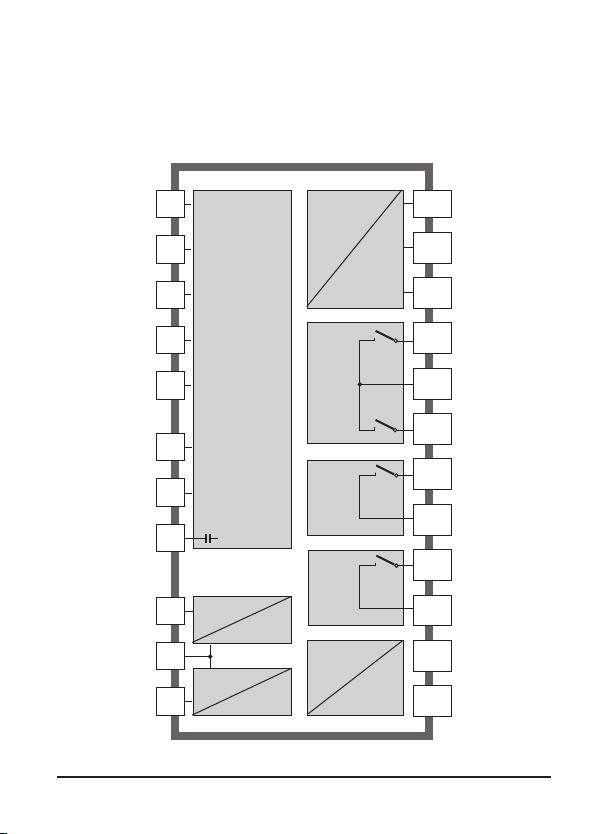
Overview of si794 D tr
Cathode
Do not
connect!
Guard
Reference
electrode
Anode
RTD
RTD
Shield
HOLD
HOLD/
CONTROL
CONTROL
1
2
3
4
5
E
D
C
6
7
8
O2 input
Temp
input
Hold
input
Control
input
Output 1
Output 2
R1
R2
Alarm
Clean
Power
9
10
11
12
13
14
15
16
17
18
19
20
+ Output 1
– Output 1/2
+ Output 2
Relay 1
Relay 1/2
Relay 2
Alarm
Alarm
Clean / PSet 2
Clean / PSet 2
Power
Power
11
Page 12
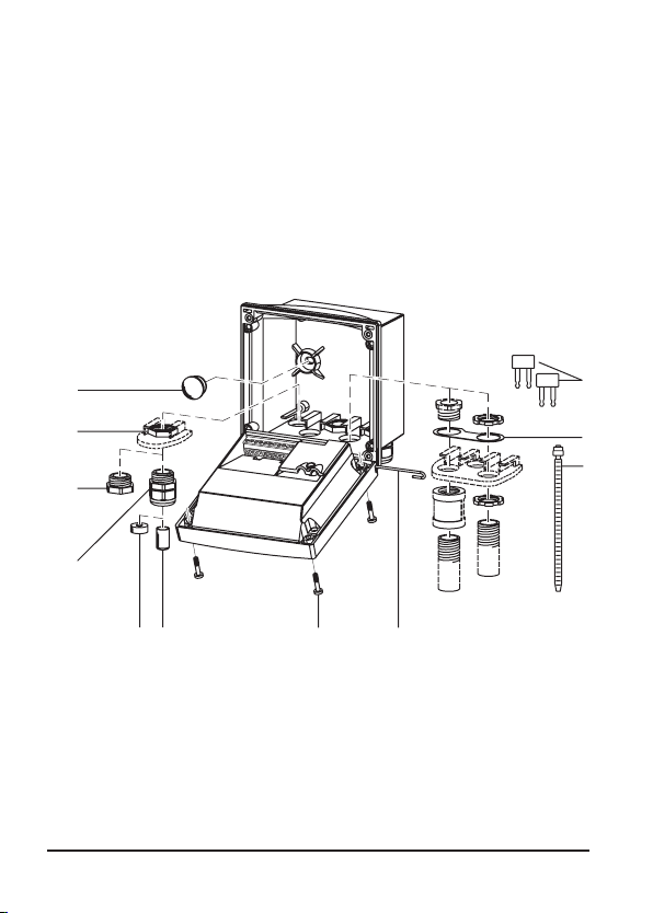
Assembly
11
10
9
8
76 5
4
1
2
3
Package contents
Check the shipment for transport damage and completeness.
The package should contain:
• Front unit
• Rear unit
• Bag containing small parts
• User manual
• Specific test report
1 Jumper (2 x)
2 Washer (1 x), for conduit
mounting: Place washer between
enclosure and nut
3 Cable tie (3 x)
4 Hinge pin (1 x), insertable from
either side
5 Enclosure screw (4 x)
Fig.: Assembling the enclosure
12
6 Sealing insert (1 x)
7 Rubber reducer (1 x)
8 Strain relief (3 x)
9 Filler plug (3 x)
10 Hex nut (5 x)
11 Sealing plug (2 x),
for sealing in case of wall mounting
Page 13
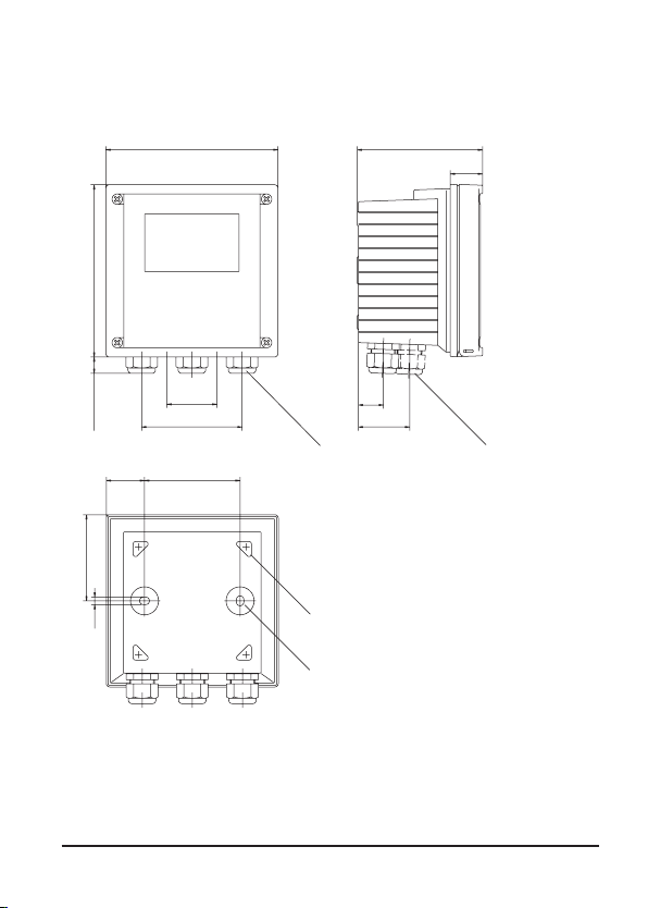
Mounting plan
144
144
15
42
84
80
32
21
43
105
27
72
6,2
12
3
4
Fig.: Mounting plan – All dimensions in mm!
1 Strain relief (3 x)
2 Strain relief or 1/2“ conduit
opening, ø 21.5 mm (2 x)
Conduit hardware not included!
3 Knockout for pipe mounting
(4 x )
4 Knockout for wall mounting
(2 x )
13
Page 14
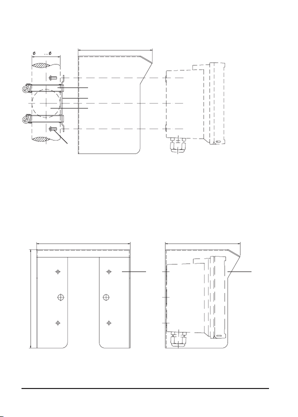
40 60
132
1
2
3
4
5
1
132165
173
1
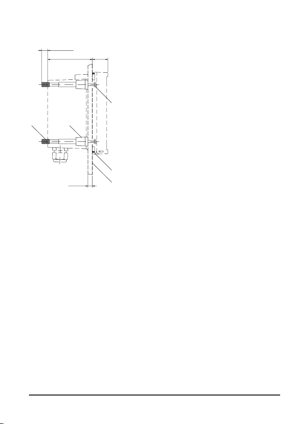
Pipe mounting, panel mounting
1 Protective hood (LZY485) - if required
2 Hose clamp with worm gear drive to DIN 3017 (2 x)
3 Pipe-mount plate (1 x)
4 For vertical or horizontal posts or pipes
5 Self-tapping screw (4 x)
Fig.: Bracket kit (LZY483) – All dimensions in mm!
Fig.: LZY485 protective hood for wall and pipe mounting
– All dimensions in mm!
14
Page 15
1
2
3
45
max. 25
78 27
1...22
1 Screw (4 x)
2 Gasket (1 x)
3 Control panel
4 Span piece (4 x)
5 Threaded sleeve (4 x)
Fig.: Panel mounting kit (LZY484) – All dimensions in mm!
15
Page 16
Installation and connection
Installation instructions
Caution!
Any work on the electrical installation may only be undertaken by
experienced and qualified personnel in accordance with the applicable
local safety regulations.
• Always disconnect power to the device when making any electrical
connections!
• Be sure to follow the instructions in the user manual!
• Only connect the power supply when all internal wirings have been
completed and the system is correctly grounded!
When using an external voltage supply, always connect a ground-fault
circuit interrupter (tripping current max. 30 mA) between mains and
controller system! A ground-fault circuit interrupter is not required
when safety extra-low voltages (24 V DC supply via rechargeable
batteries or 24 V DC/AC supply through an isolation transformer)!
When operating the system outdoors, connect a surge voltage
protection between mains and controller system!
The terminals are suitable for single wires and flexible leads up to
2.5 mm² (AWG 14). Attach end ferrules to the leads.
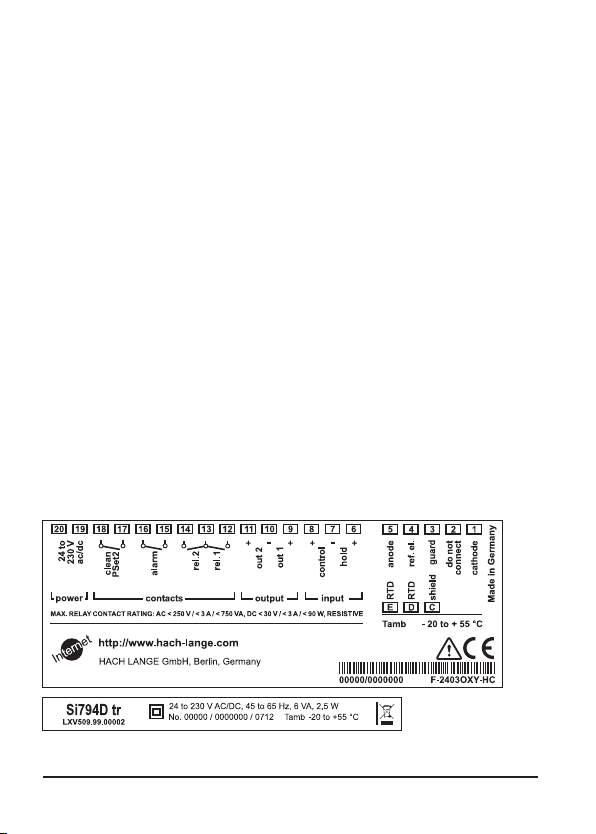
Terminal assignments
Danger of electric shock!
Fig.: si794 D tr terminal assignments
16
Page 17
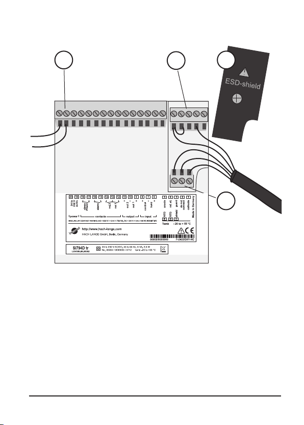
4
3
1 ESD shield covering the signal inputs
(Screw off for assembly)
Note:
The cable shield must end under the ESD shield.
(Cut lines if required)
2 Terminals for temperature probe and outer shield
3 Terminals for sensor
4 Power supply connection
1
2
Fig.: Information on installation, rear side of device
17
Page 18

18
Page 19
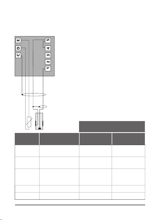
Wiring example
Hamilton Oxyferm, Oxygold G, OxySens sensors
Color
Terminal
1 Cathode Transparent,
5
Jumper to 4
C Shield:
D RTD Green Yellow
E RTD White Blue
Assignment
Anode Red,
Do not connect to
ground!
Oxyferm
Oxygold G
coax core
coax shield
Yellow/green Copper wire
Oxysens
Transparent,
coax core
Brown,
coax shield
19
Page 20
1
2
3
1
2
3
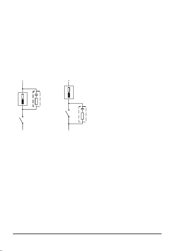
Protective wiring of relay outputs
Protective wiring of relay contacts
Relay contacts are subject to electrical erosion. Especially with
inductive and capacitive loads, the service life of the contacts will
be reduced. For suppression of sparks and arcing, components
such as RC combinations, nonlinear resistors, series resistors, and
diodes should be used.
Typical AC applications
with inductive load
1 Load
2 RC combination, e.g. RIFA PMR 209
Typical RC combinations
for 230 V AC:
Capacitor 0.1µF / 630V,
Resistor 100 ohms / 1 W
3 Contact
20
Page 21
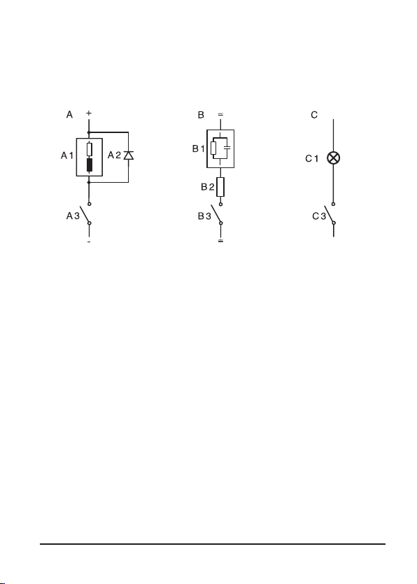
Typical protective wiring measures
A: DC application with inductive load
B: AC/DC applications with capacitive load
C: Connection of incandescent lamps
A1 Inductive load
A2 Free-wheeling diode, e.g. 1N4007 (Observe polarity)
A3 Contact
B1 Capacitive load
B2 Resistor, e.g. 8 Ω / 1 W at 24 V / 0.3 A
B3 Contact
C1 Incandescent lamp, max 60 W / 230 V, 30 W / 115 V
C3 Contact
Warning!
Make sure that the maximum ratings of the relay contacts are
not exceeded even during switching!
21
Page 22
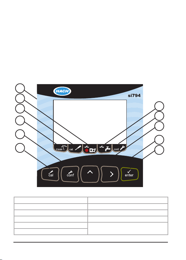
Interface and navigation
The si794 transmitter user interface contains a display, indicators,
and keys for navigation and menu selection.
User interface
Use the arrow and enter keys to scroll through the menu and
change settings. Use the indicators to identify which mode the
transmitter is in.
6
5
4
3
2
1
Fig.: si794 user interface
1 Calibration key 7 Wash mode indicator
2 Congure key 8 Conguration mode indicator
3 Measure mode indicator 9 Up arrow key
4 Calibration mode indicator 10 Right arrow key
5 Alarm indication
6 Display
11 Enter key
7
8
9
10
11
22
Page 23
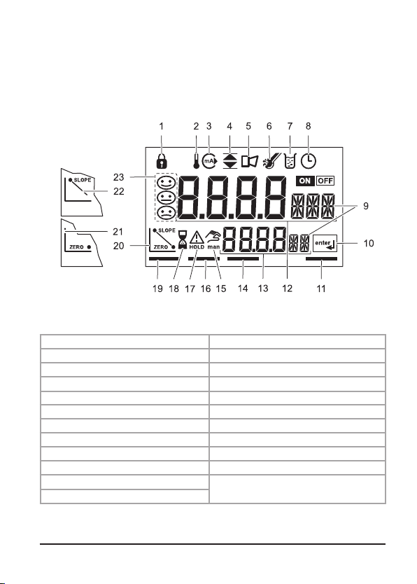
Display
Interface and navigation
4.3 Display
Figure 11 identifies all of the possible icons and symbols that may be
seen in the si792 transmitter display.
The gure below identies all of the possible icons and symbols
that may be seen in the si794 transmitter display.
Fig.: si794 display
1 Passcode 13 Secondary display
2 Temperature 14 Alarm mode
3 4–20 mA/HART output 15 Manual temperature on
4 Limit values 16 Calibration mode
5 Alarm 17 Hold mode active
6 Sensocheck: Sensor error 18 Hourglass (waiting indication)
7 Calibration active 19 Measure mode active
8 Calibration interval 20 Calibration complete
8 Parameter display 21 Calibration: zero or rst point
10 Enter prompt 22 Calibration: second point
11 Conguration mode
12 Main display
23 Sensofaces
23
Page 24
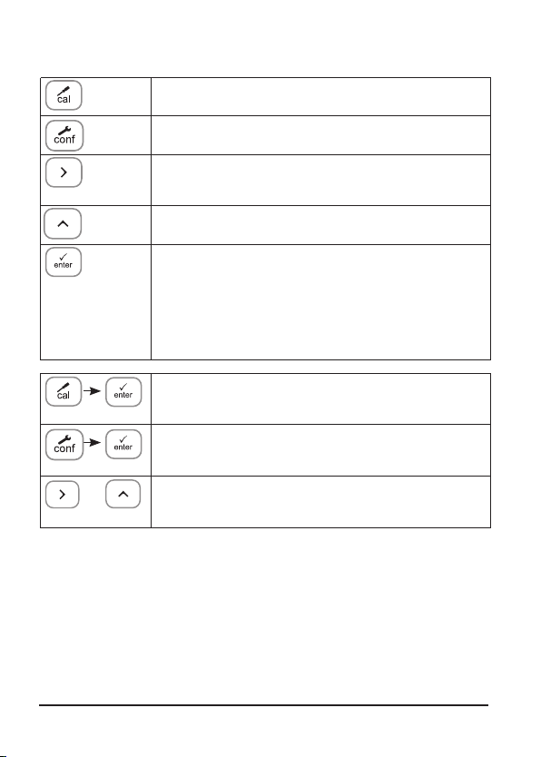
Operation: Keypad
Start, end calibration
Start, end configuration
Select digit position
(selected position blinks)
Edit digit
• Calibration:
Continue in program sequence
• Conguration: Conrm entries,
next conguration step
• Measuring mode: Display output current
Cal Info: Display of zero current and slope
Error Info: Display of last error message
24
+
Start GainCheck device self-test
Page 25
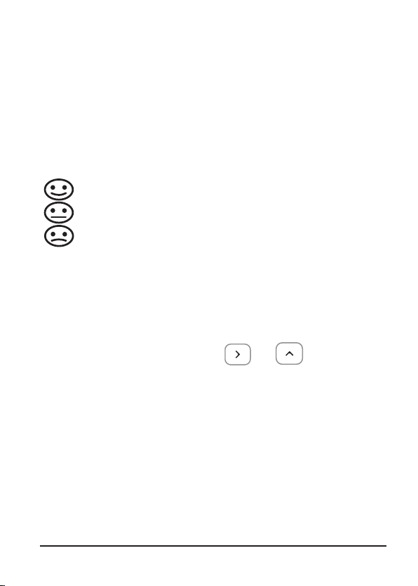
Safety features
Sensocheck, Sensoface sensor monitoring
Sensocheck continuously monitors the sensor and lines.
Sensocheck can be switched off (Configuration, Pg 49).
Sensoface provides information on the sensor condition.
The slope and response time during calibration are evaluated. The three Sensoface indicators provide the user with
information on wear and required maintenance of the
sensor.
GainCheck device self-test
A display test is carried out, the software version is displayed,
and the memory and signal transfer are checked.
Start GainCheck device self-test:
Automatic device self-test
The automatic device self-test checks the memory and signal
transfer. It runs automatically in the background at fixed intervals.
+
25
Page 26

Safety functions
Hold mode
Display:
The Hold mode is a safety state during conguration and calibration. Output current is frozen (Last) or set to a xed value (Fix).
Alarm and limit contacts are disabled.
If the calibration or conguration mode is exited, the transmitter
remains in the Hold mode for safety reasons. This prevents undesirable reactions of the connected peripherals due to incorrect
conguration or calibration. The measured value and “HOLD” are
displayed alternately. The transmitter only returns to measuring
mode after enter is pressed and 20 seconds have passed.
Conguration mode is also exited automatically 20 minutes
(timeout) after the last keystroke. The transmitter returns to
measuring mode.
Timeout is not active during calibration.
Response of output signal:
Last: The output current is frozen at its last value.
Recommended for short conguration procedures.
The process should not change decisively during conguration. Changes are not noticed with this setting!
Fix: The output current is set to a value that is noticeably
dierent from the process value in order to signal the
control system that the transmitter is being worked at.
26
Page 27
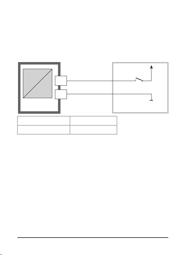
External activation of HOLD mode
The Hold mode can be activated from outside by sending a signal
to the Hold input (e.g. from the process control system).
Power supply
Hold
12...24 V AC/DC
6
input
si794
7
Process control system
Hold active Hold inactive
10 ... 30 V AC/DC 0 ... 2 V AC/DC
Alarm
The alarm delay is congurable.
During an error message the alarm LED blinks or lights.
Error messages can also be signaled by a 22 mA
output current.
The alarm contact is activated by alarm or power failure,
see also Pg 27.
The alarm LED on the front panel can be congured as follows
HOLD o: Alarm: LED blinks
HOLD on: Alarm: LED on. HOLD: LED blinks
27
Page 28
Configuration
In the Configuration mode you set the device parameters. The device can
store two different parameter sets and switch between them. Sensor data and
“Clean/Pset2” output are edited in parameter set 1 only. They are valid for
both parameter sets.
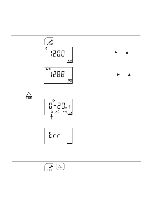
Configuring
Parameter set 1
Configure:
Press conf.
Enter mode code “1200”:
Edit parameter set 1 with and , confirm/proceed with enter.
Parameter set 2
Configure:
“88” appears in the
display.
Enter mode code “1288”:
Edit parameter set 2 with
firm/proceed with enter.
and , con-
The output current is frozen
Hold
During
configuration
the device
remains in the
Hold mode.
Input errors
HOLD icon
(at its last value or at a preset fixed
value, depending on the configuration), limit and alarm contacts are inactive. The controller is in the configured
state, Sensoface is off, mode indicator
“Configuration” is on.
The configuration parameters are
checked during the input. In the
case of an incorrect input “Err” is displayed for approx. 3 s. The incorrect
parameters cannot be stored. Input
must be repeated.
End End with conf. The measured value
and Hold are displayed alternately,
“enter” flashes. End Hold mode with
enter . The display shows the measured value. The output current remains
frozen for another 20 s (HOLD icon on,
“hourglass” flashes).
28
Page 29
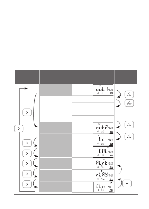
Menu structure of conguration
The conguration steps are assigned to dierent menu groups.
Use the arrow keys to jump between the individual menu
groups. Each menu group contains menu items for setting the
parameters.
Press enter to access a menu item. Use the arrow keys to edit
values. Press enter to conrm/save the settings.
To return to measurement, press conf and then enter.
Select menu
group
Menu group Code Display
Output 1 o1.
Menu item 1
Menu item 2
Menu item ...
Output 2 o2.
Temperature
compensation
Calibration mode CA.
Alarm settings AL.
Relay rL.
Cleaning contact
PSet 2 selection
tc.
Cn.
...
Select
menu item
Previous
menu
group:
29
Page 30

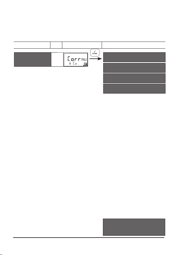
Overview of conguration steps
Code
Menu
Output 1
out1
o1.
Select sensor type
Select saturation / concentration
Select current range
Enter current start
Enter current end
Time averaging filter
22 mA signal in the case of error
Signal
response
Enter fixed value
Output 2
out2
o2.
Select temperature unit
Select temperature probe
Select current range
Enter current start
Enter current end
Time averaging filter
22 mA signal for temp error
Signal
response
Enter fixed value
Correction
Corr
Co.
Enter polarization voltage
Select pressure unit
Select process pressure correction
Enter salinity correction
Calibration mode
CAL
CA.
Select saturation / concentration
Enter cal timer interval
during HOLD
during HOLD
Choices
Standard (Type A) / Traces (Type B)
% / mg/L, ppm
0-20 mA / 4-20 mA
xxxx
xxxx
xxxx sec
ON / OFF
Last / Fix
xxx.x mA
°C / °F
22NTC / 30NTC
0-20 mA / 4-20 mA
xxx.x
xxx.x
xxxx sec
ON / OFF
Last / Fix
xxx.x mA
0675 mV / xxxx mV
bar / kPa / PSi
x.xxx bar / 1.013 bar
xx.xx mg/L
SAt / Conc
xxxx h
30
Page 31

Code
Menu
Alarm settings
ALr
Select Sensocheck
AL.
Enter alarm delay
LED in HOLD mode
Relay 1/2: Limit values, controller
rLAY
rL.
Select limit function / controller
Select contact function
L1.
Select contact response
Enter setpoint
Enter hysteresis
Enter delay
Select contact function
L2.
Select contact response
Enter setpoint
Enter hysteresis
Enter delay
Enter controller setpoint
Ct.
Enter neutral zone
(P) Controller gain K
(I) Reset time TR
(D) Rate time TD
Pulse length / Pulse frequency
PLC: Pulse length
PFC: Pulse frequency
Select HOLD response
Cleaning contact
Cln.
Select cleaning contact or signaling of
Cn.
parameter set 2
rinse
Cleaning interval
Cleaning duration
Select contact response
Choices
ON / OFF
xxxx sec
ON / OFF
LiMIT / CtROL
Lo / Hi
N/O / N/C
xxxx
xxxx
xxxx SEC
xxxx sec
N/O / N/C
xxxx
xxxx
xxxx SEC
xxxx
xxxx
xxxx %
P
xxxx SEC
xxxx SEC
PLC / PFC
xxxx SEC
xxxx /min
Y Last / Y Off
rinse / Pset2 rinse
xxx.x h 000.0 h
xxxx SEC 0060 SEC
N/O / N/C N/O
31
Page 32

Conguration
Output 1
Select sensor type / Measurement procedure
Menu group
Output 1
Code
o1.
Display
*)
Type A sensors (standard applications):
Hamilton Oxyferm
Hamilton Oxysens
Type B sensor (traces):
Hamilton Oxygold
Select menu item
Select sensor type*
Select meas. procedure
Select 0-20 / 4-20 mA
Enter current start
Enter current end
Set output filter
22 mA for error
HOLD mode
Exit:
Press conf, then enter.
Note: The si794 D tr has as device a resolution of 0.01 ppm.
32
Page 33

Code Display
o1.
After correct input a
welcome text (CONF) is
displayed for approx. 3 sec
Action
Select configuration
(Press conf key).
Enter passcode “1200”
(Select position using arrow
key and edit number using key.
When the display reads “1200”,
press enter to confirm.)
The transmitter is in the HOLD
mode (HOLD icon is active).
Select sensor Type A / B
(see table on left-hand side)
Select using arrow key.
Press enter to proceed.
Choices
Type A,
Type B
Select measurement procedure
(valid for all following settings):
• SAt: Saturation (%)
• Conc: Concentration (mg/L
or ppm)
Select using arrow key.
Press enter to proceed.
Note: Characters represented in gray are blinking and can be edited.
%
mg/L
ppm
33
Page 34

Conguration
Output 1
Output current range / Current start / Current end.
Menu group
Output 1
Code
o1.
Display
Select menu item
Select sensor type
Select meas. procedure
Select 0-20 / 4-20 mA
Enter current start
Enter current end
Set output filter
22 mA for error
HOLD mode
34
Exit:
Press conf, then enter.
Page 35

Code
o1.
Display
Action
Set output current range
Select using key.
Press enter to proceed.
Choices
4 - 20 mA
(0 - 20 mA)
Current start
Enter lower end of scale, depending on the measurement
procedure selected (Saturation or
0000 %
(mg/L,
ppm)
Concentration)
Select position using , edit number
using , press enter to proceed.
Current end
Enter upper end of scale, depending on the measurement
procedure selected (Saturation or
0100 %
(mg/L,
ppm)
Concentration)
Select position using , edit number
using , press enter to proceed.
Assignment of measured values:
Current start and current end
Example 1: Range 0 ... 100 % Example 2: Range 50 ... 70%.
[%]
Oxygen
100
saturation
0
Output current
20 4
Advantage: Higher resolution in
70
[mA]
[%]
50
range of interest
Oxygen
saturation
Output current
[mA]
20 4
35
Page 36

Conguration
Output 1
Time averaging lter
Menu group
Output 1
Code
o1.
Display
Select menu item
Select sensor type
Select meas. procedure
Select 0-20 / 4-20 mA
Enter current start
Enter current end
Set output filter
22 mA for error
HOLD mode
Exit:
Press conf, then enter.
36
Page 37

Display Action
Code
o1.
Time interval of output filter
Default setting: 0 sec (inactive).
To specify a time interval:
Select position using ,
edit number using .
Press enter to proceed.
Choices
0 sec
(0 ... 120 sec)
Time averaging filter
To smoothen the current output, a low-pass filter with adjustable
filter time can be switched on. When there is a jump at the input
(100 %), the output level is at 63 % after the time interval has been
reached.
The time interval can be set from 0 to 120 sec.
If the time interval is set to 0 sec, the current output follows the
input.
Note:
The filter only acts on the current output, not on the display, the
limit values, or the controller!
Time interval 0 to 120 sec
37
Page 38

Conguration
Output 1
Output current during Error and HOLD
Menu group
Output 1
Code
o1.
Display
Select menu item
Select sensor type
Select meas. procedure
Select 0-20 / 4-20 mA
Enter current start
Enter current end
Set output filter
22 mA for error
HOLD mode
Exit:
Press conf, then enter.
38
Page 39

Code
o1.
Display
Action
22 mA signal for error message
Select using key
Press enter to proceed.
Choices
OFF
(ON)
Output signal during HOLD
LAST: During HOLD the last
measured value is maintained at
the output
FIX: During HOLD a value (to be
entered) is maintained at the
output
Select using key
Press enter to proceed.
Only with FIX selected:
Enter current which is to flow at
the output during HOLD
Select position using key and
edit number using key.
Press enter to proceed.
Output signal during HOLD
Output current
[mA]
21
4
Output signal for HOLD
FIX setting = 21.0 mA
HOLD active
LAST
(FIX)
21.0 mA
(00.0 ...
21.0 mA)
Output signal for HOLD
LAST setting
HOLD active
39
Page 40

Conguration
Output 2
Temperature unit and probe / Output current.
Menu group
Output 2
Code
o2.
Display
Select menu item
Select °C/°F
Select temp probe
Select 0-20 / 4-20 mA
Enter current start
Enter current end
Set output filter
22 mA for temp error
HOLD mode
Exit:
Press conf, then enter.
40
Page 41

Code
o2.
Display
Action
Specify temperature unit
Select using key key.
Press enter to proceed.
Choices
°C
(°F)
Select temperature probe
Select using key key.
Press enter to proceed.
Set output current range
Select using key key.
Press enter to proceed.
Current start: Enter lower end of
scale.
Select position using , edit number
using , press enter to proceed.
Current end: Enter upper end of
scale.
Select position using , edit number
using , press enter to proceed.
Process temperature: Current start and current end
Example 1: Range 0 ... 100 °C Example 2: Range 50 ... 70 °C.
[°C]
Process
100
temperature
0
Output current
20 4
[mA]
Advantage: Higher resolution in
[°C]
70
50
range of interest
Process
temperature
Output current
22NTC
(30NTC)
4 - 20 mA
0 - 20 mA
000.0 °C
100.0 °C
[mA]
20 4
41
Page 42

Conguration
Output 2
Time averaging lter
Menu group
Output 2
Code
o2.
Display
Select menu item
Select °C/°F
Select temp probe
Select 0-20 / 4-20 mA
Enter current start
Enter current end
Set output filter
22 mA for temp error
HOLD mode
Exit:
Press conf, then enter.
42
Page 43

Code
o2.
Display
Action
Time interval of output filter
Default setting: 0 sec (inactive).
To specify a time interval:
Select position using ,
edit number using .
Press enter to proceed.
Choices
0 sec
(0 ... 120 sec)
Time averaging filter
To smoothen the current output 2, a low-pass filter with adjustable
filter time can be switched on. When there is a jump at the input
(100 %), the output level is at 63 % after the time interval has been
reached.
The time interval can be set from 0 to 120 sec.
If the time interval is set to 0 sec, the current output follows the
input.
Note:
The filter only acts on the current output, not on the display, the
limit values, or the controller!
Time interval 0 to 120 sec
43
Page 44

Conguration
Output 2
Temperature error / Output current during HOLD
Menu group
Output 2
Code
o2.
Display
Select menu item
Select °C/°F
Select temp probe
Select 0-20 / 4-20 mA
Enter current start
Enter current end
Set output filter
22 mA for temp error
HOLD mode
Exit:
Press conf, then enter.
44
Page 45

Code
o2.
Display
Action
22 mA signal for error message
Select using key.
Press enter to proceed.
Choices
OFF
(ON)
Output signal during HOLD
LAST: During HOLD the last
measured value is maintained at
the output
FIX: During HOLD a value (to be
entered) is maintained at the
output
Select using key.
Press enter to proceed.
Only with FIX selected:
Enter current which is to flow at
the output during HOLD.
Select position using key and
edit number using key.
Press enter to proceed.
Output signal during HOLD:
Output current
[mA]
21
4
Output signal for HOLD
Setting FIX = 21.0 mA
HOLD active
LAST
(FIX)
21.0 mA
(00.0 ...
21.0 mA)
Output signal for HOLD
LAST setting
HOLD active
45
Page 46
Conguration
Correction
Polarization voltage / Process pressure / Salinity correction
Menu group
Correction
Code
CO.
Display
Select menu item
Polarization voltage
Meas. unit (pressure)
Process pressure
Salinity correction
46
Exit:
Press conf, then enter.
Page 47

Code Display
Co.
Action
Enter polarization voltage
Select using , edit number
using , press enter to proceed.
Choices
0675 mV
Select pressure unit
Select using arrow key
Press enter to proceed.
Process pressure correction
Enter process pressure. This
value is used to correct oxygen
saturation. It has no influence
on concentration measurement
(Conc).
Select position using key and
edit number using key.
Press enter to proceed.
Enter salinity correction
Select position using
and edit number using .
Press enter to proceed.
* ppt (parts per thousand) - corresponds to g/kg
bar
(kPa, PSi)
1.013 bar
00.00
ppt*
47
Page 48

Conguration
Calibration mode
Alarm settings
Menu group
Calibration mode
Alarm settings
Alarm
Code
CA.
Display
Select menu item
Calibration mode
Cal timer interval
Exit:
Press conf, then enter.
AL.
Select Sensocheck
Delay
LED in HOLD mode
Exit:
Press conf, then enter.
Alarm contact
15
The alarm contact is closed during normal operation (N/C).
It opens in the case of alarm or power outage.
16
As a result, a failure message is provided even in the case
of line breakage (fail-safe behavior). For contact ratings,
see Specifications.
Error messages can also be signaled by a 22 mA
output current (see Pg 39,
The operating behavior of the alarm contact is shown
on Pg 84.
The alarm delay acts on the LED, the 22 mA signal, and the
alarm contact.
45,
83).
48
Page 49

Code
CA.
Display
Action
Specify calibration mode
(Calibration to saturation or
concentration)
Select using ,
press
enter to proceed.
Choices
SAt
(Conc)
AL.
Cal timer interval
The cal timer reminds you to
calibrate in time.
Select position using ,
edit number using ,
press
enter to proceed.
Select Sensocheck
(continuous monitoring of
sensor)
Select using ,
press
enter to proceed.
Alarm delay
Select position using , edit number
using , press
LED in Hold mode
Select position using ,
edit number using ,
press
LED status:
Setting
ON
OFF
enter to proceed.
enter to proceed.
Alarm HOLD
on blinks
blinks off
0000 h
(0 ...
9999 h)
ON/
OFF
0010 sec
(xxxx sec)
ON/
OFF
49
Page 50

Conguration
Limit Function
Relay 1
Menu group
Relay / Controller
Code
rL.
Display
Select menu item
Use of relays
Contact function
L1.
Contact response
Enter setpoint
Enter hysteresis
Delay
L2.
Relay 2 menu group
Controller menu group
Ct.
Exit:
Press conf, then enter.
50
Page 51

Code
rL.
Display
Action
Use of relays:
• Limit function (LiMIT)
• Controller (CtROL)
Select using ,
press
enter to proceed.
Note: Selecting CtROL leads to
Controller menu group Ct.
Choices
LiMIT
(CtROL)
L1.
For limit 1 function principle,
see Fig. on Pg. 53. Select using ,
press
enter to proceed.
Limit 1 contact response
N/C: normally closed contact
N/O: normally open contact
Select using
Press enter to proceed
Limit 1 setpoint
Select using , edit number using
, press
Limit 1 hysteresis
Select using , edit number using
, press
Limit 1 delay
The contact is activated with delay
(deactivated without delay)
Select position using ,
edit number using ,
press
.
enter to proceed.
enter to proceed.
enter to proceed.
Lo
(Hi)
N/C
(N/O)
0000 %
(
xxxx %)
0001 %
(
xxxx %)
0010 sec
(
0 ... 600 sec)
51
Page 52

Conguration
Limit function
Relay 2
Menu group
Relay / Controller
Code
rL.
Display
Select menu item
Use of relays
Relay 1 menu group
L1.
Contact function
L2.
Contact response
Enter setpoint
Enter hysteresis
Delay
Controller menu group
Ct.
Exit:
Press conf, then enter.
52
Page 53

Code
Display Action
Choices
L2.
Limit Lo
Hysteresis +
Setpoint
Contact
For limit 2 function principle,
see Fig. below. Select using ,
press
enter to proceed.
Limit 2 contact response
N/C: normally closed contact
Hi
(Lo)
N/C
(N/O)
N/O: normally open contact
Select using , press
enter to
proceed.
Limit 2 setpoint
Select using , edit number using
, press
enter to proceed.
Limit 2 hysteresis
Select using , edit number using
, press
enter to proceed.
Limit 2 delay
The contact is activated with delay
0500 %
(
xxxx %)
0001 %
(
xxxx %)
0010 sec
(
0 ... 600 sec)
(deactivated without delay)
Select position using ,
edit number using ,
press
enter to proceed.
Signal
1
0
Limit Hi
Setpoint
Hysteresis -
Contact
Signal
1
0
53
Page 54

Conguration
Controller (for description see page 78)
Setpoint / Neutral zone
Menu group
Relay / Controller
Code
rL.
Display
Select menu item
Use of relays
Relay 1 menu group
L1.
Relay 2 menu group
L2.
Ct.
Controller setpoint
Enter neutral zone
(P) Controller gain
(I) Reset time TR
(D) Rate time TD
Controller type PLC / PFC
PLC: Pulse length
PFC: Pulse frequency
HOLD response
Exit:
Press conf, then enter.
54
Page 55

Code Display
Ct.
Action Choices
Setpoint
Select using , edit number using
, press
enter to proceed.
Neutral zone (dead band)
Select using , edit number using
, press
enter to proceed.
Controller: P action
Select using , edit number using
, press
enter to proceed.
0100 %
(xxxx %)
0010 %
(xxxx %)
0100 %
(xxxx %)
Controller: I action (reset time)
Select using , edit number
using , press
Controller: D action (rate time)
Select using , edit number
using , press
Pulse length / Pulse frequency
Select using ,
press
enter to proceed.
PLC: Pulse length
Select using , edit number using
, press
PFC: Pulse frequency
Select using , edit number using
, press
Behavior during HOLD
Select using ,
press
enter to proceed.
enter to proceed.
enter to proceed.
enter to proceed.
enter to proceed.
0000 sec
(0 ...
9999 sec)
0000 sec
(0 ...
9999 sec)
PLC
(PFC)
0010 sec
(0 ...
600 sec)
0060/min
(0 ...
180 /min)
Y Last
(Y Off)
55
Page 56

Configuration
Controlling a rinsing probe or
Signaling parameter set 1/2
Menu group
Contact:
CLEAN / PSet2
Display
Code
Cn.
rinse
56
Code
Cn.
Display
Select menu item
Select CLEAN / PSet2
Rinsing interval
Rinse time
Contact response
Action (rinsing probe)
Function selection*:
• Control of rinsing probe (rinse)
Signaling active parameter set 2
•
Select using ,
proceed.
Rinsing interval *
Select using , edit number
, press enter to proceed.
using
Rinse duration *
Select using , edit number
, press enter to proceed.
using
Select contact response*
N/O: normally open contact
N/C: normally closed contact
Select using ,
proceed
*) These parameters are only edited in parameter set 1. They are valid for
both parameter sets.
press enter to
press enter to
Choices
rinse
(rinse /
PSet2)
For
PSet2
see next
page
000.0 h
(xxx.x h)
0060 sec
(xxxx sec)
N/O
(
N/O
N/C)
:
Page 57

Controlling a rinsing probe
The “Clean” contact can be used to connect a simple rinsing probe.
Rinse duration and rinsing interval are defined during configuration.
Contact response can be set as N/O or N/C.
e.g. spray cleaning
Clean
17
18
Signaling parameter set 1/2
Depending on the selected parameter set, the relay is
active or inactive. The signal can be used for superordinated process control systems.
Parameter set 2 is indicated by “88” in the upper left
corner of the display.
Clean
PSet2
17
18
si794
Parameter set 1 selected
Parameter set 2 selected
Power supply
Power supply
Process control system
Power supply:
AC< 250 V / < 3 A / < 750 VA
DC< 30 V / < 3 A / < 90 W
57
Page 58

Selecting parameter set 1/2
Manually or via a signal at the Control input
Display
After correct input a
welcome text (CONF) is
displayed for approx. 3 sec
Action Choices
To select a parameter set, press conf,
enter code: 7654
Select position using , edit number
using ,
Wrong settings change the measurement
properties! If an invalid code is entered, the
transmitter returns to measuring mode.
press enter to proceed.
Select:
• Parameter set 1 (MAN)
• Parameter set 2 (MAN)
• Automatic switchover via
control input (Ctr-EXT)
Select using ,
With -1- or -2- selected:
Since the complete device configuration is changed in one step, there is a
security prompt (No/Yes).
Note:
When pressing enter directly,
the selection is not stored.
Activation of parameter set 2 is
indicated by “88” in the upper left
corner of the display.
press enter to proceed.
-1-
(-1- MAN
-2-MAN
Ctr-EXT)
For Ctr-EXT,
see next
page
58
Page 59

Display
Action Choices
With Control input
You can switch between the parameter
sets by applying an external signal to
the Control input (see below).
Ctr-EXT selected:
External switchover of parameter sets
The parameter set can be selected from outside by sending a
signal to the Control input (e.g. from the process control system).
To do so, Ctr-EXT is set during configuration.
Power supply
Control
12...24 V AC/DC
7
input
si794
Note:
Parameter set 2 is indicated by “88” in the upper left corner of the
display.
8
Process control system
0 ... 2 V AC/DC Parameter set 1 selected
10 ... 30 V AC/DC Parameter set 2 selected
59
Page 60

60
Page 61

Default settings of parameter sets
Two complete parameter sets are stored in the EEPROM.
As delivered, the two sets are identical but can be edited.
Note:
Fill in your configuration data on the following pages.
Code. Parameter Default setting
o1. Sensor type A
o1. %, mg/L, ppm %
o1. 0/4-20 mA 4-20 mA
o1. Current start 0000 %
o1. Current end 0500 %
o1. Filter time 0 sec
o1. 22mA signal OFF
o1. HOLD response Last
o1. Fix current 021.0 mA
o2. Unit °C / °F °C
o2. Temp probe 22 NTC
o2. 0/4 ...20mA 4-20 mA
o2. Current start 000.0 °C
o2. Current end 100.0 °C
o2. Filter time 0 sec
o2. 22mA signal OFF
o2. HOLD response Last
o2. Fix current 021.0 mA
Co. Polariz. voltage 675 mV
Co. Pressure unit bar
Co. Pressure 1.013 bar
Co. Salinity 00.00 mg/L
CA. Cal mode Sat
CA. Cal interval 0000 h
AL. Sensocheck OFF
AL. Alarm delay 0010 sec
AL. LED Hold OFF
Code. Parameter Default setting
rL. Relay function Limit
L1. Contact function Lo
L1. Contact response N/C
L1. Setpoint 0000 %
L1. Hysteresis 0001 %
L1. Delay 0010 sec
L2. Contact function Hi
L2. Contact response N/C
L2. Setpoint 0500 %
L2. Hysteresis 0001 %
L2. Delay 0010 sec
Ct. Setpoint 0100 %
Ct. Neutral zone 0010 %
Ct. P action 0100 %
Ct. I action 0000 sec
Ct. D action 0000 sec
Ct. PLC/PFC controller PLC
Ct. Pulse length 0010 sec
Ct. Pulse frequency 0060 /min
Ct. Hold response Last
Cn. Rinse/Par.set 2 rinse
Cn. Rinsing interval 000.0 h
Cn. Rinse time 0060 sec
Cn. Contact type N/C
61
Page 62

Parameter set - individual settings
Code. Parameter Setting
o1. Sensor type ____________ ____________
o1. %, mg/L, ppm ____________ ____________
o1. 0/4-20 mA ____________ ____________
o1. Current start ____________ ____________
o1. Current end ____________ ____________
o1. Filter time ____________ ____________
o1. 22mA signal ____________ ____________
o1. HOLD response ____________ ____________
o1. Fix current ____________ ____________
o2. Unit °C / °F ____________ ____________
o2. Temp probe ____________ ____________
o2. 0/4 ...20mA ____________ ____________
o2. Current start ____________ ____________
o2. Current end ____________ ____________
o2. Filter time ____________ ____________
o2. 22mA signal ____________ ____________
o2. HOLD response ____________ ____________
o2. Fix current ____________ ____________
Co. Polarization voltage ____________ ____________
Co. Pressure unit ____________ ____________
Co. Pressure ____________ ____________
Co. Salinity ____________ ____________
CA. Cal mode ____________ ____________
CA. Cal interval ____________ ____________
AL. Sensocheck ____________ ____________
AL. Alarm delay ____________ ____________
AL. LED Hold ____________ ____________
62
Page 63

Code. Parameter Setting
rL. Relay function ____________ ____________
L1. Contact function ____________ ____________
L1. Contact response ____________ ____________
L1. Setpoint ____________ ____________
L1. Hysteresis ____________ ____________
L1. Delay ____________ ____________
L2. Contact function ____________ ____________
L2. Contact response ____________ ____________
L2. Setpoint ____________ ____________
L2. Hysteresis ____________ ____________
L2. Delay ____________ ____________
Ct. Setpoint ____________ ____________
Ct. Neutral zone ____________ ____________
Ct. P action ____________ ____________
Ct. I action ____________ ____________
Ct. D action ____________ ____________
Ct. PLC/PFC controller ____________ ____________
Ct. Pulse length ____________ ____________
Ct. Pulse frequency ____________ ____________
Ct. Hold response ____________ ____________
Cn. Rinse /Par.set2 ____________ ____________
Cn. Rinsing interval ____________ ____________
Cn. Rinse duration ____________ ____________
Cn. Contact type ____________ ____________
63
Page 64

Calibration
Calibration adjusts the transmitter to the sensor.
Activation Activate with cal
Enter passcode.
Edit parameter using and ,
conrm/proceed using enter.
(To exit, press cal, then enter.)
HOLD
During calibration the
transmitter
remains in
the Hold
mode.
Input errors
End
64
HOLD icon
During calibration the transmitter remains in the Hold mode
for reasons of safety. Output
current is frozen (last value or
preset xed value, depending
on conguration), limit and
alarm contacts are inactive. The
controller is in the congured
state, Sensoface is o, “Calibration” mode indicator is on. The
red LED blinks when “HOLD ON”
has been set.
The calibration parameters are
checked during the input. In the
case of an incorrect input “Err” is
displayed for approx. 3 sec. The
incorrect parameters cannot be
saved. Input must be repeated.
End with cal. The measured value is shown in the main display
alternately with “Hold”, “enter”
blinks, Sensoface is active. Press
enter key to end the Hold mode.
The measured value is displayed.
The output current remains
frozen for another 20 sec (HOLD
icon on, “hourglass” blinks).
Page 65

Calibration
It is always recommended to calibrate in air.
Compared to water, air is a calibration medium which is easy to
handle, stable, and thus safe. In the most cases, however, the
sensor must be dismounted for a calibration in air.
When dealing with biotechnological processes which require
sterile conditions, the sensor cannot be removed for calibration.
Here, calibration must be performed with aeration directly in the
process medium (e.g. after sterilization).
In the field of biotechnology, for example, often saturation is
measured and calibration is performed in the process medium for
reasons of sterility.
For other applications where concentration is measured (water
control etc.), calibration in air has proved to be useful.
Common combination: process variable / calibration mode
Measurement Calibration
Saturation Water
Concentration Air
The calibration procedures for these two common applications are
described on the following pages. Of course, other combinations
of process variable and calibration mode are possible.
Note:
When a 2-point calibration is required, the zero calibration should
be performed prior to saturation or concentration calibration, resp.
All calibration procedures must only be performed by trained
personnel.
65
Page 66

Calibration to percent saturation (SAT)
Display
Action
Select calibration
(Press cal.)
Enter passcode: 1100
Select position using ,
edit number using
press
enter to proceed.
Place sensor in calibration
medium
Start with enter
Enter relative humidity
Select position using ,
edit number using ,
press
enter to proceed.
Enter calibration pressure
Select position using , edit
number using , press
to proceed.
Automatic drift check
Display of sensor current (related to 25 °C and 1013 mbars)
and measuring temperature.
The drift check might take
some time.
,
enter
Remark
SAT or Conc calibration
is selected during
configuration.
If an invalid code is entered, the transmitter
returns to measuring
mode.
The transmitter is in
Hold mode
Default for relative
humidity in aqueous
media:
rH = 100 %
(in air approx. 50 %)
Default for calibration pressure is the
process pressure
configured
Drift check can
be stopped after
> 10 sec by pressing cal (accuracy
reduced).
66
Page 67

Display Action
Enter setpoint value for
saturation
Select position using ,
edit number using ,
press
Remark
Default: last value
entered
enter to proceed.
Display of new slope and
zero point (related to 25 °C at
1013 mbars)
Press enter to end calibration.
Place sensor in process.
The percent saturation is
shown in the main display
alternately with “Hold”;
“enter“ blinks.
Press enter to exit calibration.
New calibration:
Press cal key.
After end of
calibration, the outputs remain in Hold
mode for approx.
20 sec.
Information on saturation calibration (SAT)
• The calibration medium must be in equilibrium with air (percent saturation for
water is 100 %). Oxygen exchange between water and air is very slow. To speed
up the adjustment processes, make sure that there is a steady medium flow
during calibration.
• If the percent saturation is known from a simultaneous measurement, it can be
entered manually.
• For 2-point calibration, perform zero calibration first.
67
Page 68

Calibration to concentration (Conc)
Display
Action
Select calibration
(Press cal.)
Enter passcode: 1100
(Select position using
edit number using
press enter to confirm.)
Place sensor in air
Start with enter
Enter relative humidity
(Select position using
edit number using
press enter to confirm.)
Enter calibration pressure
(Select position using
edit number using
press enter to confirm.)
Automatic drift check
Display of input current (related to 25 °C and 1013 mbars)
and measuring temperature.
The drift check might take
some time.
,
,
,
,
,
,
Remark
SAT or Conc calibration
is selected during
configuration.
If an invalid code is
entered, the transmitter
returns to measuring
mode.
The transmitter
goes to HOLD
mode.
Default for relative
humidity in air:
rH = 50 %
Default for calibration pressure is
normal pressure
1.013 bars.
Drift check can be
stopped after
> 10 sec by pressing cal (accuracy
reduced).
68
Page 69

Display
Action
Enter default for concentration
(Select position using
edit number using
press enter to confirm.)
,
,
Remark
The default value
is calculated from
rel. humidity,
cal pressure, and
cal temperature.
(the unit of
measurement,
ppm or mg/L, ... ,
is preset during
configuration.)
Display of new slope and
zero point (related to 25 °C at
1013 mbars).
Press enter to end
concentration calibration.
Place sensor in process
The new value is shown in the
main display alternately with
“Hold”; “enter” blinks.
Press enter to exit calibration.
New calibration:
Press cal key.
After end of
calibration, the outputs remain in Hold
mode for approx.
20 sec.
Information on concentration calibration (Conc)
Calibration in air. This calibration method is recommended when the sensor can be
removed for calibration. Air has a stable oxygen content. Therefore the adjustment
processes during calibration run more quickly.
For 2-point calibration, perform zero calibration first.
69
Page 70

Zero calibration
Zero calibration
The sensors have a very low zero current. Therefore, a zero calibration is only recommended for measurement of oxygen traces.
If a zero calibration is performed, the DO sensor should remain
for at least 10 to 30 minutes in the calibration medium in order to
obtain stable, non-drifting values.
During zero calibration, a drift check is not performed.
Zero current of a properly functioning sensor is notably less than
0.5 % of air current. The display (bottom: measured value, top:
entered value) does not change until an input current is entered
for the zero point.
When measuring in an oxygen-free medium, the displayed
current can be taken directly.
70
Page 71

Display
Zero
Action
Select calibration
(Press cal key).
Enter passcode: 1001
Select position using ,
edit number using ,
press
enter to proceed.
Place sensor in oxygen-free
medium
Main display:
Zero current
Press enter to save the value
or correct it using the arrow
keys and then save by
pressing enter.
Secondary display:
Sensor current measured
Remark
The transmitter is in
the Hold mode.
If an invalid code is
entered, the transmitter returns to
measuring mode.
Display of slope
Display of new zero current.
Press
enter
place sensor in the process
The oxygen value is shown in
the main display alternately
with “Hold”, “enter” blinks.
Press enter to stop Hold.
to end calibration,
New calibration:
Press cal key.
After end of
calibration, the outputs remain in Hold
mode for approx.
20 sec.
71
Page 72

Product calibration
Calibration by sampling
During product calibration the sensor remains in the process.
The measurement process is only interrupted briefly.
Procedure: During sampling the currently measured value is saved in the
transmitter. The transmitter immediately returns to measuring mode.
The calibration mode indicator blinks and reminds you that calibration
has not been terminated. The comparison value is measured on the site,
e.g. using a portable DO meter in a bypass. This value is then entered in
the transmitter. The new value for slope or zero is calculated from the
stored value and the comparison value. From the measured value, the
transmitter automatically recognizes whether a new slope or zero must
be calculated (above approx. 5 % saturation: slope, below: zero).
If the sample is invalid, you can take over the measured value saved
during sampling instead of the comparison value. In that case the old
calibration values remain stored. Afterwards, you can start a new product
calibration.
The following describes a product calibration with slope correction – a
product calibration with zero correction is performed correspondingly.
Display
72
Action
Product calibration step 1:
Select calibration
(Press cal key).
Enter passcode: 1105
(Select position using
edit number using ,
press enter to confirm.)
Save value.
Press enter to proceed.
Remark
The type of product
calibration (SAT or
Conc) is selected during
configuration (mea-
,
surement procedure).
If an invalid code is
entered, the transmitter
returns to measuring
mode.
Now the reference
value must be
determined.
The transmitter
goes to measuring
mode.
Page 73

Display
Action
Remark
Measuring mode
Product calibration step 2:
When a reference value has
been determined, open the
product calibration once more
(cal key, passcode 1105).
Enter the comparison value.
Press enter to confirm.
Display of new slope and zero
(related to 25 °C and
1013 mbars)
Press enter to end calibration.
The measured value is shown
in the main display alternately
with “Hold”. “enter” blinks.
Press enter to exit calibration.
From the blinking
CAL mode indicator you see that
product calibration has not been
terminated.
Display (approx.
3 sec)
Calculation of new
slope.
New calibration:
Press cal key.
After end of
calibration, the outputs remain in Hold
mode for approx.
20 sec.
73
Page 74

Temp Probe Adjustment
Display
Action Remark
Select calibration
(Press cal key).
Enter passcode: 1015
Select position using ,
edit number using ,
press
Measurement
Display
Remark
In the measuring mode the main display shows the
configured process variable (%, mg/L, or ppm) and the
lower display the temperature.
During calibration you can return to measuring mode
by pressing the cal key, during configuration by
pressing the conf key.
(Waiting time for signal stabilization approx. 20 sec).
enter to proceed.
Ready for calibration
Measure the temperature of
the process medium using an
external thermometer.
Enter the measured value:
Select position using ,
edit number using ,
press enter to proceed.
Press enter to end adjustment.
HOLD will be deactivated after
20 sec.
Wrong settings change
the measurement
properties!
If an invalid code is
entered, the transmitter
returns to measuring
mode.
The transmitter is in the
Hold mode (display for
approx. 3 sec)
Default:
Current value of
secondary display
74
Page 75

Diagnostics functions
Display
Remark
Display of output currents
Press enter while in measuring mode.
The current at output 1 is shown in the main display,
the current at output 2 in the secondary display.
After 5 sec the transmitter returns to measuring
mode.
Display of calibration data (Cal Info)
Press cal while in measuring mode and enter code:
0000. The slope is shown in the main display, the zero
current in the secondary display.
After 20 sec the transmitter returns to measuring
mode (immediate return at pressing enter).
Display of sensor current (sensor monitor)
Press conf while in measuring mode and enter code:
2222. The (uncompensated) sensor current is shown
in the main display, the measuring temperature in
the secondary display.
Press enter to return to measurement.
Display of last error message (Error Info)
Press conf while in measuring mode and enter code:
0000. The last error message is displayed for approx.
20 sec.
After that the message will be deleted (immediate
return to measurement at pressing enter).
75
Page 76

Diagnostics functions
These functions are used for testing the connected peripherals.
Display
76
Select a
relay
Test 0/1
Return to
measurement
Action / Remarks
Specify current at output 1
• Press conf, enter code 5555
The current indicated in the main display for output 1
can be edited.
Select position using , edit number using ,
press
enter to confirm. Then the entered value will
be shown in the secondary display.
The transmitter is in Hold mode.
Press conf, then enter to return to measurement
(Hold remains active for another 20 sec).
Specify current at output 2
• Press conf, enter code 5556
The current indicated in the main display for
output 2 can be edited.
Select position using , edit number using ,
enter to confirm. Then the entered value will
press
be shown in the secondary display.
The transmitter is in Hold mode.
Press conf, then enter to return to measurement
(Hold remains active for another 20 sec).
Relay test (manual test of contacts)
• Press conf, enter code 5557
The relays are frozen. This state is indicated in the
display. The 4 digits in the display correspond to the
4 relays (as located on the terminal plate):
1. digit: R1
2. digit: R2
3. digit: AL
4. digit: CLN
Function test using arrow keys – see left column.
When exiting the function (enter), the relays are set
corresponding to the measured value.
Page 77

Display
Controller
characteristic
The arrows indicate
which relay (valve)
is active:
+100 %
Controller
output
Setpoint
-100 %
Relay 2 active
(Meas. value >
setpoint)
Relay 1 active
(Meas. value <
setpoint)
Action / Remarks
Controller test (manual specification of controller
output)
• Press conf, enter code: 5559
After function activation “Ctrl” is displayed for
approx. 3 sec. With the controller turned off, “OFF” is
displayed in addition, then return to measuring
mode.
The function is used to start up control loops or
check the actuators.
For bumpless changeover to automatic operation
(exiting this function), configure an I-action
component (reset time).
Specify value:
Select usingkey, edit number usingkey.
Press
enter to proceed.
The transmitter is in Hold mode.
Press enter to return to measurement (Hold remains
active for another 20 sec).
Controller output -100 to 0 %: Relay 2 active
Controller output 0 to +100 %: Relay 1 active
Momentary controller output (adjusted value has
not been saved yet)
77
Page 78

Controller functions
PID controller
P controller
Application in integrating systems
(e.g. closed tank, batch processes).
PI controller
Application in non-integrating systems
(e.g. aeration basin).
PID controller
The additional derivative action compensates for
measurement peaks.
Controller characteristic
Proportional
action Y
Relay 1
Setpoint
+100
P
[%]
Neutral zone Yp=0
O
2
-100
Relay 2
Note:
In Hold mode the controller output acts as configured
(Y = const. or Y = 0).
78
Page 79

Controller equations
Controller output Y = YP + YPdt + T
P action
Proportional action Y
Setpoint - Meas. value
YP =
Constant
P
*
KC
1
T
R
I action
with:
Y
P
T
R
T
D
K
C
Constant 50 % (for % O
5.00 mg/L (for mg/L)
5.00 ppm (for ppm)
Neutral zone (Y=0)
Tolerated deviation from desired value.
Example: With the setting “010 %”, a deviation of
± 5 % does not activate the controller.
Proportional action (Gradient KC [%])
dY
P
D
dt
D action
Proportional action
Reset time [s]
Rate time [s]
Controller gain [%]
or % Air)
2
100 %
Controller
50 %
output Y
X
w
KC = 500 %
10 / (1.00) 20 / (2.00)
Deviation
KC = 200 %
KC = 100 %
KC = 50 %
30 / (3.00)
40 / (4.00)
50 / (5.00)
Process variables: % / (mg/L, ppm)
79
Page 80

Controller functions
Pulse length / pulse frequency controller
Pulse length controller (PLC)
The pulse length controller is used to operate a valve as an actuator. It switches the contact on for a time that depends on the
controller output. The period is constant. A minimum ON time of
0.5 sec is maintained even if the controller output takes
corresponding values.
Output signal (relay contact) of pulse length controller
1
0
1
0
ON time (Y = 20 %)
ON time (Y = 80 %)
Pulse length
80
Page 81

Pulse frequency controller (PFC)
The pulse frequency controller is used to operate a frequencycontrolled actuator (metering pump). It varies the frequency
with which the contacts are switched on. The maximum pulse
frequency [pulses/min] can be defined. It depends on the
actuator.
The contact ON time is constant. It is automatically calculated
from the user-defined maximum pulse frequency.
Output signal (relay contact) of pulse frequency controller
1
0
1
0
ON time
Pulse frequency (Y = 20%)
Pulse frequency (Y = 80%)
81
Page 82

Error messages
(error codes)
Error Display
ERR 01
ERR 02
ERR 98
ERR 99
Measured
value
blinks
Measured
value
blinks
“ConF”
blinks
“FAIL”
blinks
Problem
Possible causes
SAT range
Sensor defective
Wrong sensor connected
Measuring range exceeded
Conc range
Sensor defective
Wrong sensor connected
Measuring range exceeded
System error
Configuration or calibration data
defective; completely reconfigure
and recalibrate the transmitter.
Memory error in device program
(PROM defective)
Factory settings
EEPROM or RAM defective
This error message only occurs
in the case of a total defect. The
transmitter must be repaired and
recalibrated at the factory.
Out 1 (22 mA)
Red LED
Alarm contact
x
xx
x
xx
x
xx
x
xx
Out 2 (22 mA)
x
x
82
Page 83

Error
ERR 03
ERR 11
ERR 12
ERR 13
ERR 21
ERR 22
ERR 23
ERR 41
ERR 33
Icon
(blinks)
Problem
Possible causes
Temperature probe
Open or short circuit
Temperature range exceeded
Current output 1
Current below 0 (3.8) mA
Current output 1
Current above 20.5 mA
Current output 1
Current span too small / too large
Current output 2
Current below 0 (3.8) mA
Current output 2
Current above 20.5 mA
Current output 2
Current span too small / too large
Rinsing probe
Communication error
Sensocheck
Sensor: connecting cable defective
• Zero error, Sensoface active, see Pg 86
• Slope error, Sensoface active, see Pg 86
out 1 (22 mA)
Red LED
Alarm contact
x
xx
x
xx
x
xx
x
xx
xx
xx
xx
x
xx
x
xx
Out 2 (22 mA)
x
x
x
x
x
• Response time exceeded, Sensoface active, see Pg 86
• Cal interval expired, Sensoface active, see Pg 86
83
Page 84

Calibration error messages
Icon blinks:
Problem
Possible causes
Slope out of range
Wrong calibration values specified (relative
humidity, pressure, saturation, concentration)
Calibration aborted after 12 minutes
Sensor defective or dirty
In addition
“CAL Err”
flashes.
• No electrolyte in the sensor
• Sensor cable insufficiently shielded or defective
• Strong electric fields influence the measurement
• Temperature fluctuation of calibration solution
Operating states
Operating
status
Measuring
Cal Info
(cal) 0000
Error Info
(conf) 0000
Calibration
(cal) 1100
Temp adjustment
(cal) 1015
Out 1
Out 2
Rel.1/2
Controller
Rel.1/2
Limit value
Cleaning
contact
Alarm contact
LED
Timeout
20
s
20
s
84
Page 85

Operating
status
Product cal 1
(cal) 1105
Product cal 2
(cal) 1105
Configuration
(conf) 1200
Parameter set 1/2
(conf) 7654
Sensor monitor
(conf) 2222
Current source 1
(conf) 5555
Current source 2
(conf) 5556
Relay test
(conf) 5557
Manual controller
(conf) 5559
Rinse function
HOLD input
Out 1
Out 2
Rel.1/2
Controller
Rel.1/2
Limit value
Cleaning
contact
Alarm contact
LED
Timeout
20
min
20
min
20
min
20
min
20
min
20
min
20
min
Explanation:
Active
as configured (Last/Fix or Last/Off)
85
Page 86

Sensoface
(Sensocheck must have been activated during configuration.)
The little smiley in the display (Sensoface) alerts to sensor
problems (defective cable, maintenance required).
The permitted calibration ranges and the conditions for a friendly,
neutral, or sad Sensoface are summarized in the following table.
Additional icons refer to the error cause.
Replace membrane module or filling solution, if required.
Type A sensors (Hamilton Oxyferm, Oxysens)
Slope
Range
25 .... 130 nA -2 ... +2 nA max. 720 sec
> 35 ... < 90 nA > - 0.3 ... < 0.3 nA ≤ 300 s ≤ 80 %
30 ... 35 nA
or
90 ... 110 nA
< 30 nA or
> 110 nA
Zero point
- 0.6 ... -0.3 nA
or
+0.3 ... +0.6 nA
< - 0.6 nA or
> 0.6 nA
Response
time
300 ... 600 s 80 ... ≤ 100 %
> 600 sec Timer expired
Cal timer
Note
The worsening of a Sensoface criterion leads to the devaluation
of the Sensoface indicator (Smiley becomes “sad”).
An improvement of the Sensoface indicator can only take place
after calibration or removal of the sensor defect.
86
Page 87

Type B sensor (Hamilton Oxygold)
Slope
Range 200 ... 550 nA -2 ... +2 nA max. 720 sec
Zero point
Response
time
Cal timer
> 250 ... < 500 nA
225 ... 250 nA
or
500 ... 525 nA
< 225 nA or
> 525 nA
Thermometer and Sensoface:
Temperature out of concentration or saturation range
> - 0.5 ... < 0.5 nA < 300 s < 80 %
-1.0 ... -0.5 nA
or
+0.5 ... +1.0 nA
< -1.0 nA or
> +1.0 nA
300 ... 600 s 80 ... ≤ 100 %
> 600 sec Timer expired
Sensocheck
Continuously monitors the sensor and leads for short circuits or
open circuits. Critical values make the Sensoface “sad” and the
corresponding icon blinks:
The Sensocheck message is also output as error message Err 33.
The alarm contact is active, the red LED is lit, output current 1 is
set to 22 mA (when configured correspondingly). Sensocheck
can be switched off during configuration (then Sensoface is also
disabled).
Exception: After a calibration a smiley is always displayed for
confirmation.
87
Page 88

88
Page 89

Appendix
Product line and accessories
Devices Order No.
si794 D tr LXV509.99.00002
Mounting accessories
Pipe-mount kit LZY483
Panel mounting kit LZY484
Protective hood LZY485
Pillar incl. protective hood and pipe-mount kit LZY576
Spare parts
Installation kit, si792 / si794 LZY486
Rear housing, si792 / si794 LZY487
89
Page 90

Specications
O2 input Type A sensor: Hamilton Oxyferm, Oxysens
Type B sensor: Hamilton Oxygold
Measuring current 0 ... 600 nA
Resolution 10 pA
Saturation (-10 ... 80 °C) 0... 120 %
Measurement error
Concentration (-10 ... 80 °C) 0000 ... 9999 µg/L
0000 ... 9999 ppb
0.000 ... 9.999 mg/L
0.000 ... 9.999 ppm
0.00 ... 50.00 ppm
Measurement error
Permissible guard current ≤ 20 µA
Polarization voltage * 0 ... 1000 mV, resolution 3 mV
Process pressure * 0 ... 9.999 bars
( ... 999.9 kPa / ... 145.0 PSI)
Salinity correction * 00.00 ... 45.00 g/kg
Sensor standardization
Operating modes * O
O2 concentration (automatic)
Product calibration
Zero calibration
Calibration range Zero point ± 2 nA
Sensor Type A Slope 25 ... 130 nA
(at 25 °C, 1013 mbars)
Calibration range Zero point ± 2 nA
Sensor Type B Slope 200 ... 550 nA
(at 25 °C, 1013 mbars)
Calibration timer * 0000 ... 9999 h
Pressure correction * 0.000 ... 9.999 bars / 999.9 kPa / 145.0 PSI
Sensocheck Monitoring for short circuits / open circuits
(can be disabled)
Sensoface Provides information on the sensor condition
1,2,3
0.5 % meas.val. + 0.1 %
1,2,3
0.5 % meas.val. + 0.005 mg/L or 0.005 ppm
saturation (automatic)
2
evaluation of zero point/slope, response time,
calibration interval, Sensocheck
90
Page 91

Temperature input NTC 22 kohms / NTC 30 kohms*
2-wire connection, adjustable
Measuring range -20.0 ... +150.0 °C / -4 ... +302 °F
Adjustment range 10 K
Resolution 0.1 °C / 1 °F
Measurement error
1,2,3
< 0.5 K (<1 K at > 100°C)
HOLD input Galvanically separated (OPTO coupler)
Function Switches transmitter to Hold mode
Switching voltage Inactive 0 ... 2 V (AC/DC)
Active 10 ... 30 V (AC/DC)
CONTROL input Galvanically separated (OPTO coupler)
Function Control input for automatic cleaning system
Switching voltage Inactive 0 ... 2 V (AC/DC)
Active 10 ... 30 V (AC/DC)
Output 1 0/4 to 20 mA, max. 10 V, floating
(galv. connected to output 2)
Process variable * O2 saturation/O2 concentration
Overrange * 22 mA in the case of error messages
Output filter * Low-pass, filter time interval 0 ... 120 s
Meas. error
1
< 0.3 % current value + 0.05 mA
Start/end of scale Configurable within selected range
Span allowed 5 ... 500 % / 0.5 ... 50 mg/L (ppm)
Output 2 0/4 to 20 mA, max. 10 V, floating
(galv. connected to output 1)
Measured variable Temperature
Overrange * 22 mA in case of temp error messages
Output filter * Low-pass, filter time interval 0 ... 120 s
Measurement error 1
< 0.3 % current value + 0.05 mA
Start/end of scale * -20 ... +150 °C / -4 ... +302 °F
Span allowed 20 ... 170 K (68 ... 338 °F)
91
Page 92

Specifications
Alarm contact Relay contact, floating
Contact rating AC < 250 V / < 3 A / < 750 VA
DC < 30 V / < 3 A / < 90 W
Contact response N/C (fail-safe type)
Response delay * 0000 ... 0600 sec
Limit values Output via relay contacts R1, R2
Contacts R1, R2, floating but inter-connected
Contact rating AC < 250 V / < 3 A / < 750 VA
DC < 30 V / < 3 A / < 90 W
Contact response * N/C or N/O
Response delay * 0000 ... 9999 s
Setpoints * Within selected range
Hysteresis * 000.0 ... 050.0 % / 00.00 ... 05.00 mg/L (ppm)
PID process controller Output via relay contacts R1, R2
(Relay R1: below setpoint,
Relay R2: above setpoint)
Setpoint specification * 0 ... 500 % / 0.00 ... 50.00 mg/L (ppm)
Neutral zone * 000.0 ... 050.0 % / 00.00 ... 05.00 mg/L (ppm)
P-action component * Controller gain Kp: 0010 ... 9999 %
I-action component * Reset time Tr: 0000 ... 9999 s
(0000 s = no integral action)
D-action component * Rate time Td: 0000 ... 9999 s
(0000 s = no derivative action)
Controller type * Pulse length controller or pulse frequency controller
Pulse period * 0001 ... 0600 s, min. ON time 0.5 s
Max. pulse frequency * 0001 ... 0180 min-1 (pulse frequency controller)
(pulse length controller)
92
Page 93

Cleaning function * Relay contact, floating,
Contact ratings AC < 250 V / < 3 A / < 750 VA
DC < 30 V / < 3 A / < 90 W
Contact response * N/C or N/O
Interval * 000.0 ... 999.9 h
(000.0 h = cleaning function switched off)
Rinse duration * 0000 ... 1999 s
Display LC display, 7-segment with icons
Main display Character height 17 mm, unit symbols 10 mm
Secondary display Character height 10 mm, unit symbols 7 mm
Sensoface 3 status indicators (friendly, neutral, sad face)
Mode indication 5 mode indicators
"meas", "cal", "alarm", "cleaning", "config"
18 further icons for configuration and messages
Alarm indication Red alarm LED in case of alarm or HOLD (user defined)
Keypad 5 keys
Service functions
Current source Current specifiable for output 1 and 2 (00.00 to 22.00 mA)
Manual controller Controller output entered directly (start of control process)
Device self-test Automatic memory test (RAM, FLASH, EEPROM)
Display test Display of all segments
Last Error Display of last error occurred
Sensor monitor Display of direct, uncorrected sensor signal
Relay test Manual control of the four switching contacts
Parameter sets Two selectable parameter sets for different applications
Data retention Parameters and calibration data > 10 years (EEPROM)
for controlling a simple rinsing system
93
Page 94

Specifications
Protection against electric shock
Safe electrical isolation of all extra-low-voltage circuits
Power supply 24 (-15%) ... 230 V AC/DC (+10%); approx. 5 VA, 2.5 W
AC: 45 ... 65 Hz; Overvoltage category II, Class II
Nominal operating conditions
Ambient temperature -20 ... +55 °C
Transport/Storage temp -20 ... +70 °C
Relative humidity 10 ... 95% not condensing
Power supply 24 (-15%) ... 230 V AC/DC (+10%)
Frequency for AC 45 ... 65 Hz
EMC EN 61326
Emitted interference Class B (residential area)
Class A for mains > 60 V DC
Immunity to interference Industry
Enclosure Molded enclosure made of PBT (polybutylene terephtalate)
Color Bluish gray RAL 7031
Assembly • Wall mounting
• Pipe mounting: Ø 40 ... 60 mm
• Panel mounting, cutout to DIN 43 700
Dimensions H 144 mm, W 144 mm, D 105 mm
Ingress protection IP 65 / NEMA 4X
Cable glands 3 knockouts for cable glands M20x1.5
2 knockouts for NPT 1/2" or rigid metallic conduit
Weight Approx. 1 kg
* User-defined
1) To IEC 746 Part 1, at nominal operating conditions
2) ± 1 count
3) Plus sensor error
against mains by double insulation to EN 61010-1
30 ... 45 mm
Sealed against panel
94
Page 95

95
Page 96

Contact information
HACH LANGE GMBH
Willstätterstraße 11
D-40549 Düsseldorf
Tel. +49 (0)2 11 52 88-320
Fax +49 (0)2 11 52 88-210
info@hach-lange.de
www.hach-lange.de
DR. BRUNO LANGE AG
Juchstrasse 1
CH-8604 Hegnau
Tel. +41(0)44 9 45 66 10
Fax +41(0)44 9 45 66 76
info@hach-lange.ch
www.hach-lange.ch
HACH LANGE APS
Åkandevej 21
DK-2700 Brønshøj
Tel. +45 36 77 29 11
Fax +45 36 77 49 11
info@hach-lange.dk
www.hach-lange.dk
HACH LANGE LDA
Av. do Forte nº8
Fracção M
P-2790-072 Carnaxide
Tel. +351 214 253 420
Fax +351 214 253 429
info@hach-lange.pt
www.hach-lange.pt
HACH LANGE KFT.
Hegyalja út 7-13.
H-1016 Budapest
Tel. +36 (06)1 225 7783
Fax +36 (06)1 225 7784
info@hach-lange.hu
www.hach-lange.hu
HACH LANGE D.O.O.
Fajfarjeva 15
SI-1230 Domžale
Tel. +386 (0)59 051 000
Fax +386 (0)59 051 010
info@hach-lange.si
www.hach-lange.si
HACH LANGE LTD
Pacific Way
Salford
GB-Manchester, M50 1DL
Tel. +44 (0)161 872 14 87
Fax +44 (0)161 848 73 24
info@hach-lange.co.uk
www.hach-lange.co.uk
HACH LANGE FRANCE
S.A.S.
33, Rue du Ballon
F-93165 Noisy Le Grand
Tél. +33 (0)1 48 15 68 70
Fax +33 (0)1 48 15 80 00
info@hach-lange.fr
www.hach-lange.fr
HACH LANGE AB
Vinthundsvägen 159A
SE-128 62 Sköndal
Tel. +46 (0)8 7 98 05 00
Fax +46 (0)8 7 98 05 30
info@hach-lange.se
www.hach-lange.se
HACH LANGE SP.ZO.O.
ul. Opolska 143 a
PL-52-013 Wrocław
Tel. +48 (0)71 342 10-83
Fax +48 (0)71 342 10-79
info@hach-lange.pl
www.hach-lange.pl
HACH LANGE S.R.L.
Str. Leonida, nr. 13
Sector 2
RO-020555 Bucuresti
Tel. +40 (0) 21 201 92 43
Fax +40 (0) 21 201 92 43
info@hach-lange.ro
www.hach-lange.ro
ΗΑCH LANGE E.Π.Ε.
Αυλίδος 27
GR-115 27 Αθήνα
Τηλ. +30 210 7777038
Fax +30 210 7777976
info@hach-lange.gr
www.hach-lange.gr
96
Page 97

HACH LANGE LTD
Unit 1,
Chestnut Road
Western Industrial Estate
IRL-Dublin 12
Tel. +353(0)1 46 02 5 22
Fax +353(0)1 4 50 93 37
info@hach-lange.ie
www.hach-lange.ie
HACH LANGE
8, Kr. Sarafov str.
BG-1164 Sofia
Tel. +359 (0)2 963 44 54
Fax +359 (0)2 866 04 47
info@hach-lange.bg
www.hach-lange.bg
HACH LANGE S.L.U.
Edif. Arteaga Centrum
C/Larrauri, 1C- 2ª Pl.
E-48160 Derio/Vizcaya
Tel. +34 94 657 33 88
Fax +34 94 657 33 97
info@hach-lange.es
www.hach-lange.es
HACH LANGE SA
Motstraat 54
B-2800 Mechelen
Tél. +32 (0)15 42 35 00
Fax +32 (0)15 41 61 20
info@hach-lange.be
www.hach-lange.be
HACH LANGE S.R.L.
Via Riccione, 14
I-20156 Milano
Tel. +39 02 39 23 14-1
Fax +39 02 39 23 14-39
info@hach-lange.it
www.hach-lange.it
HACH LANGE S.R.O.
Lešanská 2a/1176
CZ-141 00 Praha 4
Tel. +420 272 12 45 45
Fax +420 272 12 45 46
info@hach-lange.cz
www.hach-lange.cz
HACH LANGE E.P.E.
27, Avlidos str
GR-115 27 Athens
Tel. +30 210 7777038
Fax +30 210 7777976
info@hach-lange.gr
www.hach-lange.gr
HACH LANGE GMBH
Hütteldorferstr. 299/
Top 6
A-1140 Wien
Tel. +43 (0)19 12 16 92
Fax +43 (0)19 12 16 92-99
info@hach-lange.at
www.hach-lange.at
DR. LANGE NEDERLAND B.V.
Laan van Westroijen 2a
NL-4003 AZ Tiel
Tel. +31(0)344 63 11 30
Fax +31(0)344 63 11 50
info@hach-lange.nl
www.hach-lange.nl
HACH LANGE S.R.O.
Rolnícka 21
SK-831 07 Bratislava –
Vajnory
Tel. +421 (0)2 4820 9091
Fax +421 (0)2 4820 9093
info@hach-lange.sk
www.hach-lange.sk
HACH LANGE
SU ANALİZ SİSTEMLERİ
LTD.ŞTİ.
Hilal Mah. 75. Sokak
Arman Plaza No: 9/A
TR-06550 Çankaya/
ANKARA
Tel. +90 (0)312 440 98 98
Fax +90 (0)312 442 11 01
bilgi@hach-lange.com.tr
www.hach-lange.com.tr
97
Page 98

Limited warranty
Hach Company warrants its products to the original purchaser
against any defects that are due to faulty material or workmanship
for a period of two years from date of shipment unless otherwise
noted in the product manual.
In the event that a defect is discovered during the warranty
period, Hach Company agrees that, at its option, it will repair or
replace the defective product or refund the purchase price excluding original shipping and handling charges. Any product repaired
or replaced under this warranty will be warranted only for the
remainder of the original product warranty period.
This warranty does not apply to consumable products such as
chemical reagents; or consumable components of a product, such
as, but not limited to, lamps and tubing.
Contact Hach Company or your distributor to initiate warranty
support.
Products may not be returned without authorization from Hach
Company.
Limitations
This warranty does not cover:
• Damage caused by acts of God, natural disaster, labor unrest,
acts of war (declared or undeclared), terrorism, civil strife or acts
of any governmental jurisdiction
• Damage caused by misuse, neglect, accident or improper
application or installation
• Damage caused by any repair or attempted repair not authorized
by Hach Company
• Any product not used in accordance with the instructions
furnished by Hach Company
• Freight charges to return merchandise to Hach Company
98
Page 99

• Freight charges on expedited or express shipment of warranted
parts or product
• Travel fees associated with on-site warranty repair
This warranty contains the sole express warranty made by Hach
Company in connection with its products. All implied warranties,
including without limitation, the warranties of merchantability
and tness for a particular purpose, are expressly disclaimed.
Some states within the United States do not allow the disclaimer
of implied warranties and if this is true in your state the above
limitation may not apply to you. This warranty gives you specic
rights, and you may also have other rights that vary from state to
state.
This warranty constitutes the nal, complete, and exclusive statement of warranty terms and no person is authorized to make any
other warranties or representations on behalf of Hach Company.
Limitation of remedies
The remedies of repair, replacement or refund of purchase price
as stated above are the exclusive remedies for the breach of this
warranty. On the basis of strict liability or under any other legal
theory, in no event shall Hach Company be liable for any incidental or consequential damages of any kind for breach of warranty
or negligence.
99
Page 100

Index
22 mA in the case of error 38
88, display icon 59
A
Access codes 108
Accessories 89
Alarm 27
Alarm contact 48
Alarm delay 48
Alarm settings 48
Assembly 12
B
Bracket kit (LZY483) 14
C
Cal Info 75
Calibration 64
Calibration error messages 84
Calibration mode 48
Calibration to concentration (Conc) 68
Calibration to percent saturation (SAT) 66
Calibration with sampling 72
“Clean” contact 57
Complaints 47
Complaints 98
Conguration 28
100
 Loading...