

Page 1
DOC273.52.00147
Chain Mount Kit LZX914.99.12400
Instruction Sheet
Page 2

© HACH LANGE GmbH, 2007. All rights reserved. Printed in Germany.
Page 3
Instruction Sheet
Chain Mount Kit LZX914.99.12400
Introduction
This instruction sheet describes the installation of the chain mou nt kit for 1½-inch NPT thread
45° (Cat. No. LZX914.99.12400).
Items supplied are shown in Figure 1 on page 3. Not all items in the hardware set are required.
Only the parts used in these instructions are listed.
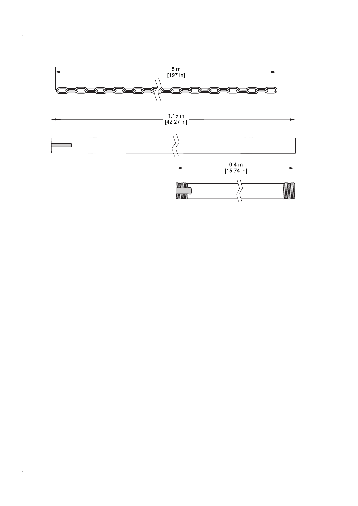
Installation dimensions are shown in Figure 2 on page 4.
DOC273.52.00147
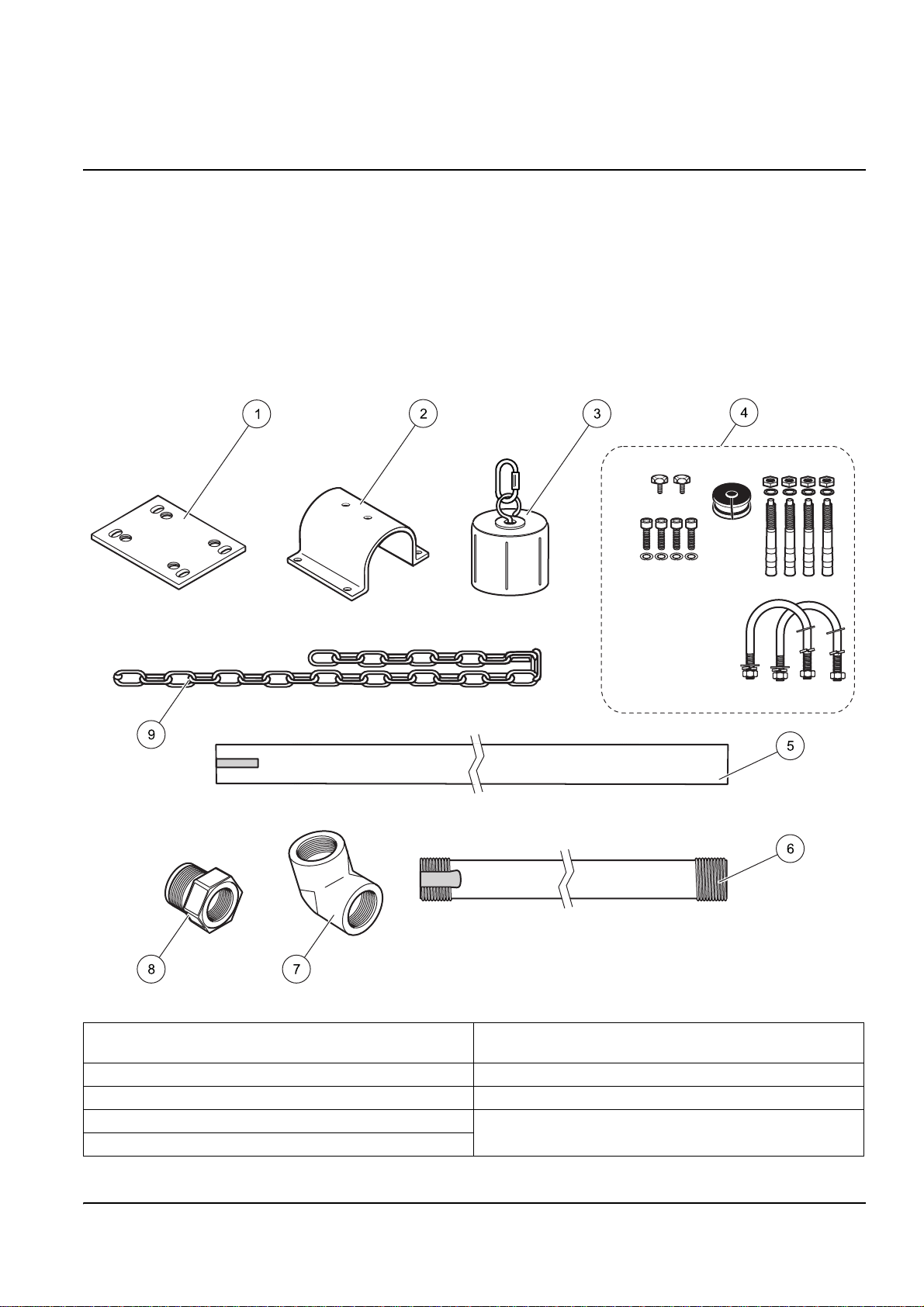
Figure 1 Items supplied with the chain mount kit (LZX914.99.12400)
1 Mounting plate 6 Immersed pipe with 1½-in. NPT thread, 400 mm long
(see Figure 2 on page 4 for dimensions)
2 Arm bracket 7 Elbow, 45°, 2 x 1½-in. NPT thread
3 Screw top 8 Reducer
4 Set of small parts 9 Plastic chain (see Figure 2 on page 4 for dimensions)
5 Arm (see Figure 2 on page 4 for dimensions)
3
Page 4
Chain Mount Kit LZX914.99.12400
Figure 2 Installation dimensions
Selecting the installation location
Important note: Refer to the sensor user manual when installing the mounting hardware.
Note all safety instructions and hazards.
Note: When selecting the installation location, always ensure there is safe access to all parts of the
system and that the sensor can never hit the tank wall.
During the selection of the installation location, pay attentio n to:
• The load bearing capacity and strength of the ground or railings (leverage due to flow
and installation)
• The maximum cable and tubing lengths
• The flow conditions
• The space required to remove the sensor for cleaning
Note: Refer to the sensor user manual for sensor-specific installation requirements.
4
Page 5

Installing the chain bracket on the ground
1. Find a suitable installation location and install the quick-fit anchors.
2. Drill the mounting holes (Figure 3 on page 6).
3. Fit the quick-fit anchors in the ground.
4. Hit the head of the quick-fit anchor with a hammer to sprea d th e qu ick- fit an ch or in
the hole.
5. Install the mounting plate on the quick-fit anchors.
6. Mount the arm and the arm bracket on the mounting plate and secure the arm using
the two bolts from the set of small parts (Figure 4 on page 6).
7. Guide the chain through the mounted arm and secure at the rear.
8. Install the sensor on the immersed pipe.
• Installation without cleaning unit—Guide the sensor cable through the red ucer , the
elbow and the immersed pipe and bolt all pieces together (Figure 5 on page 7).
Chain Mount Kit LZX914.99.12400
• Installation with cleaning unit—Guide the sensor cable and the air tubing through
the elbow and the immersed pipe and bolt all pieces together (Figure 6 on
page 8).
9. Guide the sensor cable (or sensor cable and air tub ing ) ou t of the sid e of th e
immersed pipe (Figure 5 on page 7 and Figure 6 on page 8).
• For installation without a cleaning unit, fit the plug from the hardware set above
the sensor cable.
Important note: Ensure the sensor cable (or sensor cable and air tubing) cannot be
rubbed, crushed or cut.
10. Install the screw cap on the immersed pipe.
11. Fit the chain to the screw cap.
12. Guide the sensor cable (or sensor cable and air tubing) through the mounted arm.
Fasten the sensor cable (or sensor cable and air tubing) to the arm (e.g. using cable
ties) or leave it hanging free.
13. Check whether the chain is correctly secured in the arm, pivot the immersed tube over
the edge of the tank and align the arm and chain. Adjust the length of the chain .
a. Adjust the distance to the tank wall using the arm.
b. Set the immersion depth using the length of the chain and set the direction in
which the sensor is installed by turning the chain in the arm.
Note: Ensure the chain is always secured and cannot be pulled out of the arm. Otherwise the
sensor and chain can fall into the tank. It possible, align the sensor such that the flow arrives at
the rear.
14. Tighten all bolts.
15. Connect the sensor to a controller.
5
Page 6

Chain Mount Kit LZX914.99.12400
16. When installing a cleaning unit, connect the air tubing to the compressed air supply.
Figure 3 Installing the quick-fit anchors
Figure 4 Installing on the ground
6
Page 7

Chain Mount Kit LZX914.99.12400
aaaa
aaaa
aa
aa
aa
Figure 5 Installing on the ground without a cleaning unit
7
Page 8

Chain Mount Kit LZX914.99.12400
aaa
aaa
aa
aa
aa
8
Figure 6 Installing on the ground with a cleaning unit
Page 9

Installing the chain bracket on a railing
1. Find a suitable installation location and install the mounting plate on the railings using
the U-bolts.
2. Proceed as described in Installing the chain bracket on the ground on page 5, step 4.
Refer to Figure 7, Figure 8 on page 10, and Figure 9 on page 11 for rail mounting details.
Chain Mount Kit LZX914.99.12400
Figure 7 Rail mounting
9
Page 10

Chain Mount Kit LZX914.99.12400
aaa
aaa
10
Figure 8 Installing on railin gs without a cleaning unit
Page 11

Chain Mount Kit LZX914.99.12400
aaa
aaa
Figure 9 Installing on railings with a cleaning unit
11
Page 12

Contact
HACH LANGE GMBH
Willstätterstraße 11
D-40549 Düsseldorf
Tel. +49 (0)2 11 52 88-0
Fax +49 (0)2 11 52 88-143
info@hach-lange.de
www.hach-lange.com
DR. BRUNO LANGE AG
Juchstrasse 1
CH-8604 Hegnau
Tel. +41(0)44 9 45 66 10
Fax +41(0)44 9 45 66 76
info@hach-lange.ch
www.hach-lange.ch
HACH LANGE APS
Åkandevej 21
DK-2700 Brønshøj
Tel. +45 36 77 29 11
Fax +45 36 77 49 11
info@hach-lange.dk
www.hach-lange.dk
HACH LANGE LTD
Pacific Way
Salford
GB-Manchester, M50 1DL
Tel. +44 (0)161 872 14 87
Fax +44 (0)161 848 73 24
info@hach-lange.co.uk
www.hach-lange.co.uk
HACH LANGE FRANCE S.A.S.
33, Rue du Ballon
F-93165 Noisy Le Grand
Tél. +33 (0)1 48 15 68 70
Fax +33 (0)1 48 15 80 00
info@hach-lange.fr
www.hach-lange.fr
HACH LANGE AB
Vinthundsvägen 159A
SE-128 62 Sköndal
Tel. +46 (0)8 7 98 05 00
Fax +46 (0)8 7 98 05 30
info@hach-lange.se
www.hach-lange.se
HACH LANGE LTD
Unit 1, Chestnut Road
Western Industrial Estate
IRL-Dublin 12
Tel. +353(0)1 46 02 5 22
Fax +353(0)1 4 50 93 37
info@hach-lange.ie
www.hach-lange.ie
HACH LANGE SA
Motstraat 54
B-2800 Mechelen
Tél. +32 (0)15 42 35 00
Fax +32 (0)15 41 61 20
info@hach-lange.be
www.hach-lange.be
HACH LANGE S.R.L.
Via Riccione, 14
I-20156 Milano
Tel. +39 02 39 23 14-1
Fax +39 02 39 23 14-39
info@hach-lange.it
www.hach-lange.it
DR. BRUNO LANGE GES. MBH
Industriestraße 12
A-3200 Obergrafendorf
Tel. +43 (0)27 47 74 12
Fax +43 (0)27 47 42 18
info@hach-lange.at
www.hach-lange.at
DR. LANGE NEDERLAND B.V.
Laan van Westroijen 2a
NL-4003 AZ Tiel
Tel. +31(0)344 63 11 30
Fax +31(0)344 63 11 50
info@hach-lange.nl
www.hach-lange.nl
HACH LANGE S.L.U.
Edif. Arteaga Centrum
C/Larrauri, 1C- 2ª Pl.
E-48160 Derio/Vizcaya
Tel. +34 94 657 33 88
Fax +34 94 657 33 97
info@hach-lange.es
www.hach-lange.es
HACH LANGE LDA
Av. do Forte nº8
Fracção M
P-2790-072 Carnaxide
Tel. +351 214 253 420
Fax +351 214 253 429
info@hach-lange.pt
www.hach-lange.pt
HACH LANGE KFT.
Hegyalja u. 7-13.
H-1016 Budapest
Tel. +36 (0 6)1 225 7783
Fax +36 (06)1 225 7784
info@hach-lange.hu
www.hach-lange.hu
HACH LANGE D.O.O.
Fajfarjeva 15
SI-1230 Domžale
Tel. +386 (0)59 051 000
Fax +386 (0)59 051 010
info@hach-lange.si
www.hach-lange.si
HACH LANGE SP.ZO.O.
ul. Opolska 143 a
PL-52-013 Wrocław
Tel. +48 (0)71 342 10-83
Fax +48 (0)71 342 10-79
info@hach-lange.pl
www.hach-lange.pl
HACH LANGE S.R.L.
str. A viator Teodor Iliescu nr.37,
Sector 1
RO-011672, Bucuresti
Tel. +40 (0)21 2 08 95 78
Fax +40 (0)21 2 08 95 78
info@hach-lange.ro
www.hach-lange.ro
ΗΑCH LANGE E.Π.Ε.
Αυλίδος 27
GR-1 15 27 Αθήνα
Τηλ . +30 210 7777038
Fax +30 210 7777976
info@hach-lange.gr
www.hach-lange.gr
HACH LANGE S.R.O.
Lešanská 2a/1176
CZ-141 00 Praha 4
Tel. +420 272 12 45 45
Fax +420 272 12 45 46
info@hach-lange.cz
www.hach-lange.cz
HACH LANGE
8, Kr. Sarafov str.
BG-1164 Sofia
Tel. +359 (0)2 963 44 54
Fax +359 (0)2 866 04 47
info@hach-lange.bg
www.hach-lange.bg
HACH LANGE E.P.E.
27, Avlidos str
GR-115 27 Athens
Tel. +30 210 7777038
Fax +30 210 7777976
info@hach-lange.gr
www.hach-lange.gr
HACH LANGE S.R.O.
Roľnícka 21
SK-831 07 Bratislava – Vajnory
Tel. +421 (0)2 4820 9091
Fax +421 (0)2 4820 9093
info@hach-lange.sk
www.hach-lange.sk
HACH LANGE SU
ANALİZ SİSTEMLERİ LTD.ŞTİ.
Hilal Mah. 75. Sokak
Arman Plaza No: 9/A
TR-06550 Çankaya/ANKARA
Tel. +90 (0)312 440 98 98
Fax +90 (0)312 442 11 01
bilgi@hach-lange.com.tr
www.hach-lange.com.tr
 Loading...