

Page 1
DOC022.52
User Manual
Gel filled ORP/Redox Probe: Model MTC10101, MTC10103,
MTC10105, MTC10110, MTC10115 or MTC10130
Safety information
Precautionary labels
Read all labels and tags attached to the instrument. Personal injury or damage to the
instrument could occur if not observed. A symbol on the instrument is referenced in the
manual with a precautionary statement.
Electrical equipment marked with this symbol may not be disposed of in European public disposal systems after
12 August of 2005. In conformity with European local and national regulations (EU Directive 2002/96/EC), European
electrical equipment users must now return old or end-of-life equipment to the Producer for disposal at no charge to
the user.
Note: For return for recycling, please contact the equipment producer or supplier for instructions on how to return end-of-life
equipment, producer-supplied electrical accessories, and all auxiliary items for proper disposal.
Specifications
Note: Specifications are subject to change without notice.
.80033
Specifications Details
Probe type Digital combination electrode with a non-refillable Ag/AgCl reference and a
built-in temperature sensor
Range ±1200 mV
Resolution 0.1 mV
Temperature accuracy ±0.3 °C (±0.54 °F)
Operating temperature range 0 to 80 °C (32 to 176 °F)
Storage temperature range 5 to 40 °C (41 to 104 °F)
Junction Open junction
Reference potential versus Standard
Hydrogen Electrode
Reference electrolyte Electrode filling solution, 3M KCl
Reference type Ag/AgCl (3 M KCl)
Minimum sample depth 20 mm
Dimensions (standard) Diameter: 12 mm (0.47 in.)
Dimensions (rugged) Diameter: 46 mm (1.81 in.)
207 mV at 25 °C
Length: 175 mm (6.89 in.)
Cable length: 1 or 3 m (3.28 or 9.84 ft)
Length: 223 mm (8.73 in.)
Cable length: 5, 10, 15 or 30 m (16.40, 32.81, 49.21 or 98.42 ft)
Cable connection M12 digital output and connector compatible with HQd meters
Product overview
The MTC101 series probe is a non-refillable, gel-filled combination oxidation reduction
potential (ORP/Redox) probe with a built-in temperature sensor (Figure 1). The
MTC10101 or MTC10103 probe is available with a 1 or 3 m (3.28 or 9.84 ft) cable and is
intended for laboratory use. The MTC10105, MTC10110, MTC10115 or MTC10130 probe
1
Page 2
is available with a 5, 10, 15 or 30 m (16.40, 32.81, 49.21 or 98.42 ft) cable and is
intended for field use. The probe measures absolute mV values in wastewater, drinking
water and general applications.
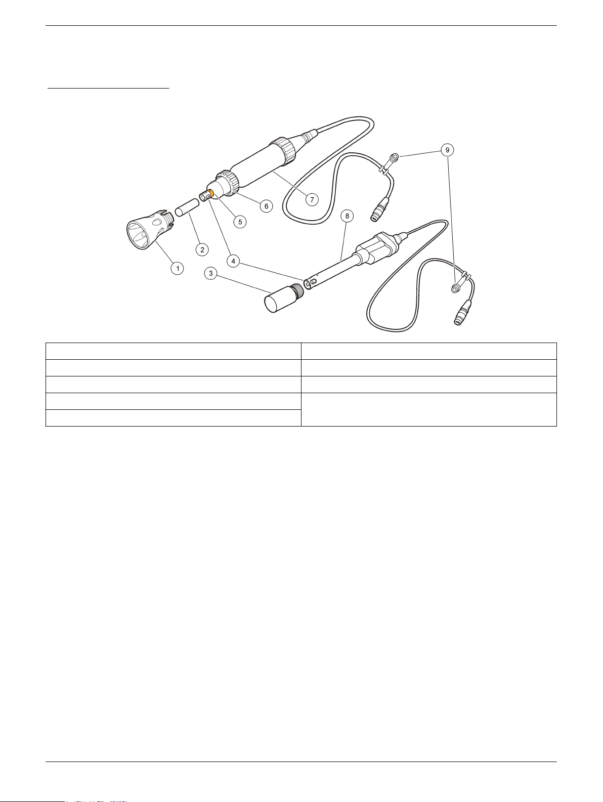
Figure 1 Probe overview
1 Shroud (rugged model) 6 Locking ring (rugged model)
2 Probe storage cap 7 Rugged probe (5, 10, 15 or 30 meter cable)
3 Probe soaker bottle 8 Standard probe (1 or 3 meter cable)
4 Platinum electrode and temperature sensor 9 Probe storage cap or soaker bottle holder
5 Reference junctions and protective tape (rugged model)
Preparation for use
To prepare the probe for initial use:
1. If a rugged probe, remove the shroud and probe storage cap (refer to Remove the
shroud on page 11
2. If a standard probe, turn the probe soaker bottle cap counter-clockwise to loosen the
cap. Remove the soaker bottle from the probe.
3. If a rugged probe, remove the protective tape from the reference junctions (refer to
Figure 1 on page 2). Dispose of the protective tape.
4. If the probe will be used immediately, prepare the probe for calibration or sample
measurement.
5. If the probe will not be used immediately, store the probe (refer to Storage
on page 11).
To prepare the probe for calibration or sample measurement:
1. If a rugged probe, remove the probe storage cap.
2. If a standard probe, turn the probe soaker bottle cap counter-clockwise to loosen the
cap. Remove the soaker bottle from the probe.
3. Rinse the reference junctions and electrode thoroughly with deionized water to
remove the 3 M KCl solution completely. Blot dry with a lint-free cloth.
4. If a rugged probe, make sure that the shroud is installed before field use (refer to
Install the shroud on page 11).
Note: Damage to the sensing elements can occur if the shroud is not installed during field use.
Damage under these conditions is not covered by the product warranty.
).
2
Page 3
Calibration
Before calibration:
The probe must have the correct service-life time stamp. Set the date and time in the meter before the probe is attached.
It is not necessary to recalibrate when moving a calibrated probe from one HQd meter to another if the additional meter is
configured to use the same calibration options.
To view the current calibration, push , select View Probe Data, then select View Current Calibration.
If any two probes are connected, push the UP or DOWN arrow to change to the single display mode in order to show the
Calibrate option.
Prepare the probe for use (refer to Preparation for use on page 2).
If a rugged probe, remove the shroud from the probe (refer to Remove the shroud on page 11).
Calibration notes:
•
Additional standards can be selected in the Calibration Options.
• Do not dilute ORP/Redox standards. Use fresh ORP/Redox standard for calibration.
• ZoBell’s redox potential is temperature dependent. The HQd calibration routine
factors in this temperature dependency allowing accurate calibrations within the
temperature range of 0 to 30 °C (32 to 86 °F). Light’s solution should be read at 25 °C
(77 °F). Custom ORP/Redox calibration solution values and temperature are userdefined.
• The calibration is recorded in the probe and the data log. The calibration is also sent
to a PC, printer or flash memory stick if connected.
• Air bubbles under the sensor tip when submerged can cause slow response or error
in measurement. If bubbles are present, gently shake the probe until bubbles are
removed.
• If a calibration error occurs, refer to Troubleshooting on page 12.
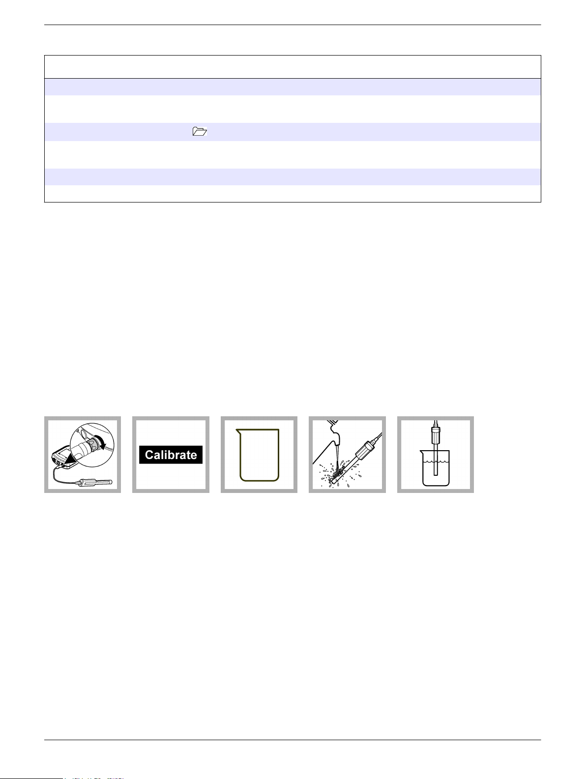
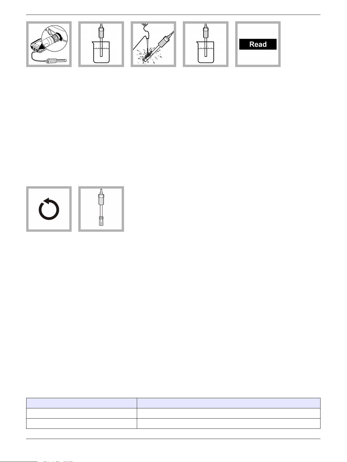
1. Connect the
probe to the
meter. Make sure
that the cable
locking nut is
securely
connected to the
meter. Turn on the
meter.
Calibration procedure:
2. Push
Calibrate. The
display shows the
ORP/Redox
standard solution
that is necessary
for calibration.
3. Add the fresh
ORP/Redox
standard solution
to a beaker or an
appropriate
container.
4. Rinse the
probe with
deionized water.
Blot dry with a lintfree cloth.
5. Put the probe
in the standard
solution so that
the temperature
sensor is
completely
submerged. Stir
gently. Shake the
probe from side to
side in the sample
to refresh the
reference junction.
3
Page 4
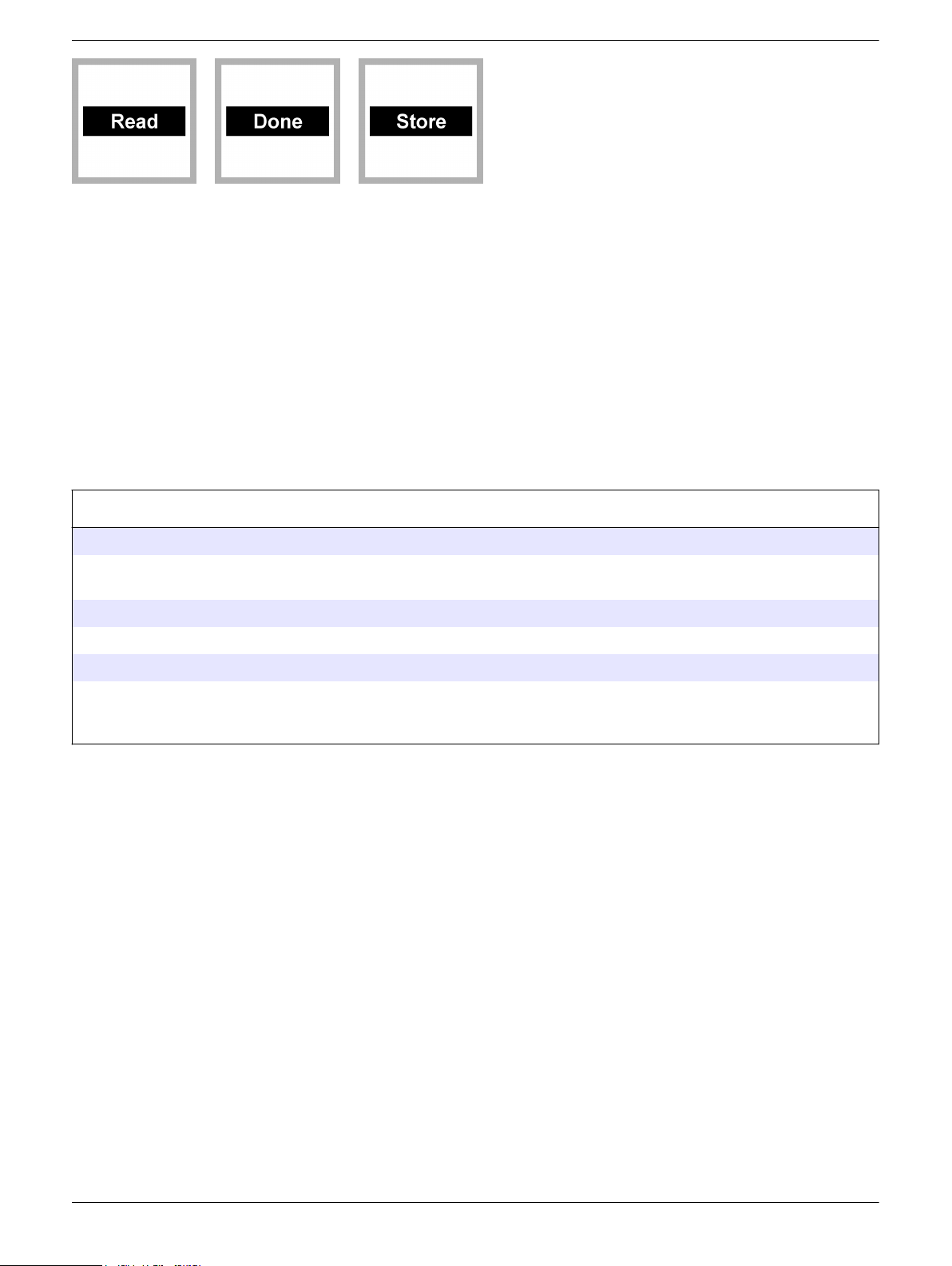
6. Push Read.
Stir gently. The
display will show
"Stabilizing" and a
progress bar as
the probe
stabilizes in the
sample. The
display shows the
standard solution
value and the mV
offset when the
reading is stable.
7. Push Done to
view the
calibration
summary.
8. Push Store to
accept the
calibration and go
back to the
measurement
mode. If a rugged
probe, install the
shroud on the
probe (refer to
Install the shroud
on page 11).
Sample measurement
Before measurement:
The probe must have the correct service-life time stamp. Set the date and time in the meter before the probe is attached.
If complete traceability is necessary, enter a sample ID and operator ID before measurement. Refer to the HQd meter
manual for more information.
Regular calibration is required for the best measurement accuracy (refer to Calibration on page 3).
Prepare the probe for use (refer to Preparation for use on page 2).
Make sure that the platinum disc is clean and smooth (refer to Clean the probe on page 11).
To deploy a rugged probe at a distance, toss the probe body with a gentle underhand throw. Do not swing the probe by the
cable as this may cause injury to the user, will cause severe strain on the cable and will shorten the service life of the cell.
Damage under these conditions is not covered by the product warranty.
Measurement notes:
•
Data is automatically stored in the data log when Press to Read or Interval is
selected in the Measurement Mode. When Continuous is selected, data will only be
stored when Store is selected.
• Air bubbles under the sensor tip when submerged can cause slow response or error
in measurement. If bubbles are present, gently shake the probe until bubbles are
removed.
• If a measurement error occurs, refer to Troubleshooting on page 12.
Measurement—direct method procedure:
4
Page 5
1. Connect the
probe to the
meter. Make sure
that the cable
locking nut is
securely
connected to the
meter. Turn the
meter on.
2. To significantly
reduce the
stabilization time
for reducing-type
samples, put the
platinum disc in
Reducing Solution
for ORP
Electrodes for
3-10 minutes
before the initial
sample
measurement.
3. Rinse the probe
with the sample.
4. Put the probe in
the sample and
stir gently. Make
sure that the
reference
junctions are
completely
submerged. Do
not put the probe
on the bottom or
sides of the
container. Shake
the probe from
side to side in the
sample to refresh
the reference
junction.
5. Push Read.
The display will
show "Stabilizing"
and a progress
bar as the probe
stabilizes in the
sample. The
display will show
the lock icon when
the reading
stabilizes. If
necessary for the
application, record
the sample pH
and temperature.
6. Repeat steps
3-6 for additional
measurements.
Temperature (°C) Electrode potential in mV (E
7. When
measurements
are done, store
the probe (refer to
Storage
on page
11).
Measurement—conversion to SHE reference procedure:
For some applications, it is customary to report redox potential readings relative to the
standard hydrogen electrode (SHE), also called normal hydrogen electrode (NHE). To do
this, select the value in Table 1
that corresponds to the temperature of the solution
measured. Substitute that value Eref into the equation and solve for Eh:
Eh = E + E
ref
where:
Eh = oxidation reduction potential of the sample relative to the SHE
E = potential developed by the ORP/Redox electrode
E
= potential developed by the reference electrode portion relative to the SHE
ref
(Table 1).
Table 1 shows the potentials, E
, developed by the reference electrode portion relative
ref
to the SHE at various temperatures.
Table 1 Standard potential of reference electrode
)
ref
80 163.1
75 167.7
5
Page 6

Table 1 Standard potential of reference electrode (continued)
Temperature (°C) Electrode potential in mV (E
70 172.1
65 176.4
60 180.3
55 184.4
50 188.4
45 192.3
40 196.1
35 199.8
30 203.4
25 207.0
20 210.5
15 214.0
10 217.4
5 220.9
0 224.2
Measurement—oxidation titrations procedure:
Oxidation-reduction, or redox titrations, give a simple, reliable method to identify many
substances in a solution. A redox titration consists of adding to an unknown sample, small
increment of a titrant that converts the unknown to a different oxidation state. After each
addition of titrant, the ORP/Redox electrode develops a potential proportional to the
logarithm of the ratio of the activities of the two oxidation states.
At the inflection, or end point, the titrant has completely oxidized or reduced the unknown,
causing a sharp change in the logarithm of the ratio of the activities of the two oxidation
states. A corresponding sharp change in the potential is developed by the platinum
electrode. Often several oxidizing or reducing species can be precisely identified in the
same solution by a single titration with several inflection points.
ref
)
6
Page 7
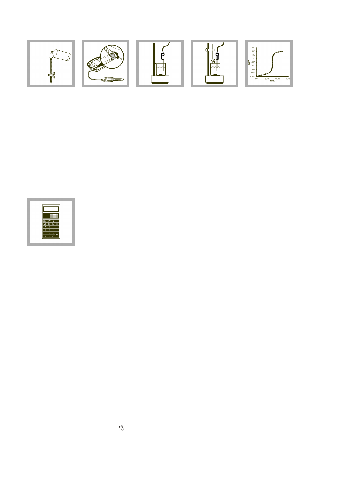
The following directions represent a general procedure for doing a redox titration once the
sample is prepared for measurement.
1. Fill a 10 mL
burette with a
standard titrant
solution with a
normality that is
5-10 times that of
the sample.
6. Calculate the
normality of the
sample, Nx, in
equivalents per
liter:
Nx = (Vt x Nt) / V
where:
Nt = normality of
titrant (Eq/L)
Vt = volume of
titrant at end point
(mL)
Vx = Volume of
sample (mL)
2. Connect the
probe to the
meter.
x
3. Pipet a 50 mL
sample into a 150mL beaker. Stir
with a magnetic
stirrer throughout
the titration.
4. Add titrant in
0.5 to 1 mL
increments.
Record the
potential after
each addition.
Near the end
point, when large
potential changes
are seen, add
increments of
0.1 to 0.2 mL.
Continue the
titration 3 to 4 mL
past the end point.
5. Plot the
electrode potential
versus volume of
added titrant and
fit a smooth curve
through the points.
The end point is
the point of
inflection (the
point of greatest
slope).
Run a check standard
The run check standard feature validates instrument performance between sample
measurements. Use the run check standard feature for periodic or user-defined interval
measurements of a traceable standard solution. Set the criteria for check standards from
the MTC101
Note: Access control must be off or a valid password must be entered before any of the check
standard method options can be changed.
1. Push
2. Select Run Check Standard.
Note: Select the correct probe if two probes are connected to the meter.
Settings menu.
. The Full Access Options menu is shown.
7
Page 8

3. Get the standard solution shown on the display.
4. Rinse the probe with deionized water. Blot dry with a lint-free cloth.
5. Put the probe in the standard solution until the temperature sensor is completely
submerged. Move the probe up or down or gently tap on the beaker to remove air
bubbles from the probe.
6. Push Read. The display will show "Stabilizing" and a progress bar as the reading
stabilizes. The display shows the value of the check standard and either Check
Standard Passed or Check Standard Failed.
7. If the display shows Check Standard Passed, the check standard measurement is
within the accepted limits set by the administrative user. Select Done to continue with
the sample measurement.
8. If the display shows Check Standard Failed, the measurement is outside of
accepted limits set by the administrative user and a recalibration is recommended. If
the acceptance criteria is set to Cal Expires on Failure: Yes, the display shows the
calibration icon and a question mark until the probe is recalibrated. To correct the
probe calibration and status indicator, calibrate the probe (refer to Calibration
on page
Advanced operation
Parameter-specific settings can be changed through the Full Access Options menu.
Details about menu navigation, available options and how to change them are given in
the screens, tables and procedures throughout this section.
3).
The settings that can be changed are shown in Table 2.
Setting Options
Measurement Options
Calibration Options
Check Standards Options
• Response time
• Upper and lower range limits (defines pH limits per method)
• Standard
• Calibration reminder
• Offset limit
• Standard value (if Custom option is selected)
• Standard (temperature compensated for ZoBell’s and Light’s solutions)
• Check standard reminder
• Acceptance criteria
• Standard value (at 25 °C if Custom option is selected)
Table 2 Parameter-specific settings
8
Page 9

Change measurement options
Methods are groups of default or user-defined settings relevant to specific applications. If
the meter is set to the default method and the Modify Current Settings option is chosen, a
prompt for a new name is shown after the changes are entered. The settings are saved
with this name to distinguish them from the default method settings, which cannot be
changed. A saved method can be used instead of multiple adjustments to the individual
settings. Changes made to a user defined method are automatically saved with the
existing name. Multiple methods can be saved for the same probe on each meter.
1. Make sure a probe is connected to the meter.
2. Push and select MTC101 Settings.
3. Select Modify Current Settings.
4. Select Measurement Options and update the settings:
Option Description
Response Time Sets the response time—
Measurement
Limits
Fast (2 mV/minute)
•
• Medium (1 mV/minute) (default)
• Slow (0.5 mV/minute)
The response time affects the speed of the measurement by adjusting the
stabilization criteria.
Sets the measurement limits—Lower limit (default: -1200.0 mV) or Upper
limit (default: 1200.0 mV).
The measurement limits can be set to match the acceptable values for
the sample. When the measurement is above the upper limit setting or
below the lower limit setting, the meter shows an "Out of limits" message.
This message is an alert to a potential problem with the process
conditions.
5. If prompted, enter a name for the new method settings. Additional changes made to
the settings of an existing method are automatically saved with the same method
name.
6. Push EXIT until the meter returns to the measurement mode.
Change calibration options
1. Make sure a probe is connected to the meter.
2. Push
3. Select Modify Current Settings.
4. Select Calibration Options and update the settings:
Option Description
Standard Sets the calibration standard—
and select MTC101 Settings.
ZoBell’s (221mV – 25 °C)
•
• Light’s (468mV – 25 °C)
• Custom
Temperature compensated for ZoBell’s solution.
Standard values are shown on the Calibration Options screen.
Light’s solution is characterized at 25 °C.
Custom standard values and temperature are user-defined.
9
Page 10

Option Description
Offset Limits Sets the offset limits—±1 mV to 250 mV (default: ±25 mV).
Standard
Value
5. Select Calibration Reminder and update the settings:
Option Description
Reminder
Repeat
Expires Calibration expires after the selected time—Immediately, Reminder +
6. If prompted, enter a name for the new method settings. Additional changes made to
the settings of an existing method are automatically saved with the same method
name.
7. Push EXIT until the meter returns to the measurement mode.
Change check standard options
1. Make sure a probe is connected to the meter.
2. Push and select MTC101 Settings.
3. Select Modify Current Settings.
4. Select Check Standards Options and update the settings:
The offset must fall within set limits for successful calibration.
When Standard is set to Custom, sets the values for the custom calibration
standard— -1200.00 to 1200.0 mV (default: +221.0 mV). Custom standards
are characterized at 25 °C.
Meter will make an audible sound when a calibration is due and repeat the
sound at the selected interval—Off (default), 1 d, 7 d or 30 d.
30 min, Reminder + 1 h, Reminder + 2 h or Continue Reading.
Note: The meter cannot be used to read samples after calibration has
expired unless Continue Reading is selected.
Option Description
Standard Sets the check standard—
ZoBell’s (221 mV – 25 °C) (default)
•
• Light’s (135 mV – 25 °C)
• Custom
Temperature compensated for ZoBell’s solution.
Standard value for check standard.
Standard value is shown on Check Standard Options screen.
Lights solution is characterized at 25 °C.
Custom standard values and temperature are user-defined.
Standard
Value
When Standard is set to Custom, enter the standard value using the up/down
arrow keys— -1200.0 to 1200.0 mV (default: 221.0 mV).
The value and temperature for custom check standard are user-defined.
5. Select Check Standard Reminder and update the settings:
Option Description
Reminder Repeat Sets the time interval for the check standard reminder—Off (default), 1 d,
7 d or 30 d.
Allow Defer Allows the postponement of check standard reminders—Yes (default) or
No.
10
Page 11

Maintenance
Clean the probe
6. Select Acceptance Criteria and update the settings:
Option Description
Acceptance Limits Sets the tolerance limits for check standard—-±1 mV to 25 mV
(default: ±10 mV).
Cal Expires on Failure Recalibration required if check standard fails—Yes or No (default).
7. If prompted, enter a name for the new method settings. Additional changes made to
the settings of an existing method are automatically saved with the same method
name.
8. Push EXIT until the meter returns to the measurement mode.
Clean the probe when:
Drifting/inaccurate readings or slow stabilization time occurs as a result of
•
contamination on the platinum disc or the probe being left dry for extended periods of
time.
• Measurement values are outside the calibration/measurement range of the probe
even after a calibration is done using freshly prepared standards.
Note: After cleaning is done, condition the platinum electrode in representative sample before use.
For general cleaning (including oils, greases and organics):
Remove the shroud
Install the shroud
1. Rinse the probe with deionized water and blot dry with a lint-free cloth.
2. Put the probe sensor and platinum disc in Electrode Cleaning Solution or warm
detergent solution for up to 15 minutes.
Note: The platinum disc can be polished using a soft cloth or cotton swab with detergent
solution.
3. Rinse the probe sensor and platinum disc with deionized water. Blot dry with a lintfree cloth.
For inorganic deposits:
1. Put the platinum disc in a solution of 0.1 M hydrochloric or nitric acid solution for up to
15 minutes.
2. Rinse the probe sensor and platinum disc with deionized water. Blot dry with a lintfree cloth.
1. Loosen and remove the locking ring.
2. Slide the shroud and locking ring off the probe.
1. Put the locking ring on the probe with the threads toward the probe.
2. Slide the shroud on the probe until it is against the locking groove.
3. Hand-tighten the locking ring on the shroud.
Storage
Short-term and long-term storage
For the best probe performance, do not let the reference junction dry out.
1. Rinse the probe with deionized water. Dry the probe with a lint-free cloth.
11
Page 12

2. Fill the probe storage cap or soaker bottle half full with Hach Electrode Storage
Solution or 3 M potassium chloride (KCl) solution.
3. If a rugged probe, put the probe storage cap on the probe.
4. If a standard probe, put the soaker bottle on the probe and tighten the soaker bottle
cap.
5. Make sure that the solution in the storage cap or soaker bottle completely covers the
reference junction.
Note: The probe can also be stored in a sample for up to 2 hours if the sample pH is not high.
Troubleshooting
Message or symptom Possible cause Action
Probe not supported Software not updated To download the most current version of the software,
refer to the applicable product page on the
manufacturer's website.
Refer to the HQd Series meter manual for specific
instructions for the meter model.
HQd meter does not support IntelliCAL
probe
®
Contact a Technical Support Representative.
Connect a probe or probe
requires service
Standard not recognized
error
mV reading is same for all
solutions
Slow stabilization time Contaminated reference junctions
Probe not connected correctly Disconnect, then connect the probe. Tighten the
Software not updated To download the most current version of the software,
Large number of methods stored on the
probe
Damaged probe Make sure there is connectivity with another probe or
Storage cap or soaker bottle not
removed
Incorrect or contaminated standard
solution
Storage cap or soaker bottle not
removed
Electrical issue Contact a Technical Support Representative.
locking nut.
refer to the applicable product page on the
manufacturer's website.
Refer to the HQd Series meter manual.
Continue to let the probe connect. Do not disconnect
the probe.
meter to confirm isolated issue with probe. Contact a
Technical Support Representative.
Remove the storage cap or soaker bottle from the
probe.
Use fresh standard solution as specified in the
method.
Remove the storage cap or soaker bottle from the
probe.
1. Thoroughly rinse the reference junction holes
with deionized water. Shake the probe while
holding it downward to remove any air bubbles.
2. Put the probe in 3.0 M KCl storage solution for
1-2 hours.
12
Page 13

Message or symptom Possible cause Action
Slow stabilization time Contaminated platinum sensor Clean the probe (refer to Clean the probe
on page
11).
Probe not conditioned/pre-treated for
reducing type samples
Low sample temperature or temperature
difference between samples
Platinum electrode not conditioned for
reducing-type samples
Air bubbles around inner reference
electrode
To significantly reduce the response time for reducing
type samples the platinum disc must undergo the
following:
1. Make sure that the platinum disc is clean and
smooth.
2. Put the platinum disc in Reducing Solution for
ORP Electrodes for 3-10 minutes before sample
analysis.
3. Rinse the probe with sample, then measure.
Check the sample temperature. The lower the
temperature or the greater the difference of
temperatures between samples, the longer the
response time.
1. Make sure that the platinum disc is clean and
smooth.
2. Put the platinum disc in Reducing Solution for
ORP Electrodes for 3-10 minutes before sample
analysis.
3. Rinse the probe with sample, then measure.
Gently tap the probe with hand or shake the probe
while holding the probe downward in the
solution/sample to remove any air bubbles in the
reference junction holes.
Out of range Measure value is outside the
calibration/measurement range of the
probe
Air bubbles around inner reference
electrode
Calibrate again using freshly prepared standards.
Clean the probe and calibrate again.
Make sure that the sample is within the range of the
probe.
Gently tap the probe with hand or shake the probe
while holding the probe downward in the
solution/sample to remove any air bubbles in the
reference junction holes.
13
Page 14

Message or symptom Possible cause Action
Drifting/Inaccurate
readings
Out of limits Check standard value is outside of limits
Contaminated platinum disc Clean the probe (refer to Clean the probe
Clogged reference Thoroughly rinse the reference junction holes with
Improper storage conditions The probe may not function correctly if the probe has
Electromagnetic Forces (EMF) such as
voltaic cells, thermoelectric devices,
electrical generators, resistors and
transformers.
Air bubbles around inner reference
electrode
set in the current method
on page
deionized water. Gently tap the probe with hand while
holding the probe downward to remove any air
bubbles.
been left dry for extended periods of time.
1. Clean or condition the probe and attempt to
2. If recalibration fails, attempt to recondition the
3. Rinse the probe with deionized water before use.
Do not test in areas where EMF is present. For testing
in process units (i.e. spot checking), make sure that
the equipment is grounded.
Gently tap the probe with hand or shake the probe
while holding the probe downward in the
solution/sample to remove any air bubbles in the
reference junction holes.
Make sure that the standard is within the limits of the
current method.
11).
recalibrate the probe.
reference junctions by putting the probe tip in a
3.0 M KCl storage solution for 1-2 hours.
Measurement value is outside of
measurement limits set in the current
method.
Calibration adjustment offset value
outside the limits set in the current
method
Storage cap or soaker bottle not
removed
Temperature out of range Calibration temperature value is outside
of range
Measured temperature is outside range
of the probe
Check standard temperature value is
outside of range
Create a new method that expands the acceptable
limits.
Make sure that the sample is within the limits of the
current method.
Create a new method with an expanded range.
Make sure that the standard is within the limits of the
current method.
Create a new method that expands the acceptable
limits.
Remove the storage cap or soaker bottle.
Make sure that the sample temperature is within the
range of the probe.
Make sure that the temperature sensor is working
correctly.
Make sure that the standard temperature is within the
range of the probe.
Make sure that the temperature sensor is working
correctly.
Make sure that the Check Standard temperature is
within the range of the probe.
14
Page 15

15
Page 16

HACH COMPANY World Headquarters
P.O. Box 389, Loveland, CO 80539-0389 U.S.A.
Tel. (970) 669-3050
(800) 227-4224 (U.S.A. only)
Fax (970) 669-2932
orders@hach.com
www.hach.com
HACH LANGE GMBH
Willstätterstraße 11
D-40549 Düsseldorf, Germany
Tel. +49 (0) 2 11 52 88-320
Fax +49 (0) 2 11 52 88-210
info@hach-lange.de
www.hach-lange.de
HACH LANGE Sàrl
6, route de Compois
1222 Vésenaz
SWITZERLAND
Tel. +41 22 594 6400
Fax +41 22 594 6499
©
Hach Company/Hach Lange GmbH, 2011, 2013. All rights reserved. Printed in U.S.A.
05/2013, Edition 3
 Loading...