

Page 1
DOC273.52.00146.Jun06
Cleaning set LZY367
Installation instructions
Page 2

Page 3
Installation instructions
Cleaning set LZY367
Introduction
These installation instructions describe the installation and use of the cleaning set LZY367.
Items supplied, cleaning set LZY367
DOC273.52.00146Jun06
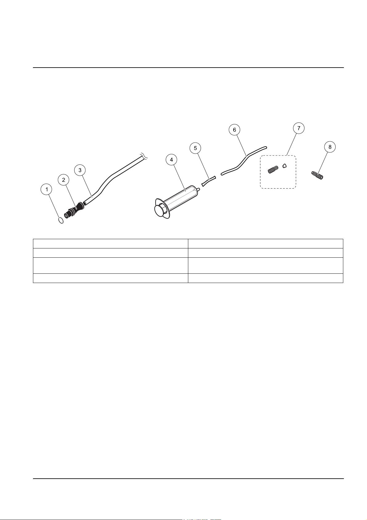
Figure 1 Items supplied, cleaning unit LZY367
1 O-ring (7.5 x 2.5 NBR), 2 pieces 5 PharMed tubing
2 Cleaning adapter for FILTRATION PROBE sc, 2 pieces 6 Tubing (2 m long, 3.2 x 0.8), LZY195
3 Tubing (4 x 1, 0.7 m), 2 pieces 7 Set of fittings (3.2 mm) LZY111
Tapered insert and union nut (2 pieces each)
4 Disposable syringe (20 mL) 8 Blind plug, 2 pieces, LZY193
Selecting the installation location
Note: Ensure you have the operating instructions
for the analysis instrument DOC023.XX.00025.YYYyy or DOC023.XX.00026.YYYyy
(xx= language, YYYyy= date) and
the FILTRATION PROBE sc DOC023.XX.00024.YYYyy
(xx= language, YYYyy= date) at hand.
Note: When selecting the installation location, ensure the tray used and the FILTRATION PROBE sc are
securely mounted and chemicals cannot leak.
During the selection of the installation location, pay attention to
• Ease of access to the enclosure door for the analysis instrument,
• The maximum cable and tubing lengths and
• Ease of access to the display module.
1
Page 4

Cleaning set LZY367
Installation of the cleaning set LZY367
Danger!
NEVER use 3% chlorine bleach together with 5% hydrochloric acid
(Risk of the formation of chlorine gas).
The chemicals used, in particular the chlorine bleach, are not allowed to be mixed
or come into contact with other chemicals (Risk of the formation of chlorine gas).
Take suitable protective measures for the chemicals used. If necessary wear
personal safety equipment (e. g. gloves and safety glasses).
Important note: Pay attention to the applicable safety data sheets, warning instructions
on the packaging and containers, and the applicable health and safety regulations.
Observe the local regulations and protect the environment on the disposal of chemicals.
Only clean the FILTRATION PROBE sc in a suitable tray.
Pay attention to all hazard and safety instructions in the operating instructions for the
analysis instrument and the FILTRATION PROBE sc.
1. Take the FILTRATION PROBE sc out of the tank; during this process pay attention to
the installation instructions for the fastening system used.
2. Place the FILTRATION PROBE sc in the tray provided.
3. Remove the filter elements (see Figure 2 Removing the filter elements on page 5) and
store them so they remain moist.
4. Use 3% chlorine bleach (e. g: LCW811, diluted 1:3 with water) OR 5% hydrochloric
acid as the cleaning solution.
5. Fill a container with cleaning solution and place the container near the FILTRATION
PROBE sc.
6. Fit the O-rings (see Figure 1 Items supplied, cleaning unit LZY367 on page 1), grease
the O-rings lightly and connect the cleaning adapters instead of the filter elements
(see Figure 3 Fitting cleaning adapters on page 5).
7. Hang the ends of the tubes on the cleaning adapters in the container with the cleaning
solution (see Figure 4 Installation overview on page 6).
2
Page 5

Cleaning the FILTRATION PROBE sc
1. Ensure all steps in section Installation of the cleaning set LZY367 on page 2 have
been performed.
2. Open the main menu on the analysis instrument.
3. Select the menu MAINTENANCE>TEST/MAINT>PREPUMPING>PREPUMPING
PROBE and trigger a pump cycle.
4. Wait until the pump cycle is complete.
Note: Ensure the tubes are not drained!
5. Hang the ends of the tubes on the cleaning adapters in a container filled with clean
water and trigger a further pump cycle.
6. Wait until the pump cycle is complete.
7. Remove the cleaning adapters and re-fit the filter elements (see Figure 5 Installing the
filter elements on page 6).
Cleaning set LZY367
8. Replace the FILTRATION PROBE sc in the tank; during this process pay attention to
the installation instructions for the fastening system used.
3
Page 6

Cleaning set LZY367
Cleaning the analyser
1. Place the analysis instrument in the service state.
a. For this purpose open the main menu on the analysis instrument.
b. Select the menu MAINTENANCE>TEST/MAINT>SERVICE MODE and choose
2. Assemble the cleaning set as shown in the drawing Figure 6 Cleaning set assembled
on page 7.
3. Remove the tube connection on the overflow vessel at the bottom right and fit the
blind plug (see Figure 7 Fitting the blind plug and the cleaning set on page 8).
4. Fill the syringe with cleaning solution.
5. Remove the sample feed tube for the FILTRATION PROBE sc on the bottom of the
overflow vessel and fit the tube connection for the cleaning set (see Figure 7 Fitting
the blind plug and the cleaning set on page 8).
6. Inject cleaning solution into the overflow vessel until it is completely full.
START.
Note: Do not fill the overflow vessel with too much cleaning solution, as the cleaning solution can
leak through the outlet in an uncontrolled manner.
7. After 5 minutes draw off the cleaning solution and dispose of the cleaning solution
with due attention for the protection of the environment.
8. Rinse the syringe and the overflow vessel with clean water.
9. Re-fit all tubes and tube connections as before.
10. Open the MAINTENANCE menu level by pressing the back arrow.
Note: The following question appears on the display: SERV. HOLD MODE?
11. Choose the answer: NO / MEASURE START.
4
Page 7

Cleaning set LZY367
Figure 2 Removing the filter elements
Figure 3 Fitting cleaning adapters
5
Page 8

Cleaning set LZY367
Figure 4 Installation overview
Figure 5 Installing the filter elements
6
Page 9

Cleaning set LZY367
Figure 6 Cleaning set assembled
1 Disposable syringe (20 mL) 4 Union nut from set of fittings, LZY111
2 PharMed tubing 5 Tapered insert from set of fittings, LZY111
3 Tubing (2 m long, 3.2 x 0.8), LZY195
7
Page 10

Cleaning set LZY367
Figure 7 Fitting the blind plug and the cleaning set
Spare parts and accessories
Description Number Order number
Tubing (2 m long, 3.2 x 0.8) 1 LZY195
Blind plug 2 LZY193
Fittings (3.2 mm) 4 (1 set) LZY111
8
Page 11

Warranty, liability and complaints
HACH LANGE GmbH warrants that the product supplied is free of
material and manufacturing defects and undertakes the obligation
to repair or replace any defective parts at zero cost.
The warranty period for instruments is 24 months. If a service
contract is taken out within 6 months of purchase, the warranty
period is extended to 60 months.
With the exclusion of the further claims, the supplier is liable for
defects including the lack of assured properties as follows: all those
parts that, within the warranty period calculated from the day of the
transfer of risk, can be demonstrated to have become unusable or
that can only be used with significant limitations due to a situation
present prior to the transfer of risk, in particular due to incorrect
design, poor materials or inadequate finish will be improved or
replaced, at the supplier's discretion. The identification of such
defects must be notified to the supplier in writing without delay,
however at the latest 7 days after the identification of the fault. If the
customer fails to notify the supplier, the product is considered
approved despite the defect. Further liability for any direct or
indirect damages is not accepted.
If instrument-specific maintenance and servicing work defined by
the supplier is to be performed within the warranty period by the
customer (maintenance) or by the supplier (servicing) and these
requirements are not met, claims for damages due to the failure to
comply with the requirements are rendered void.
Any further claims, in particular claims for consequential damages
cannot be made.
Consumables and damage caused by improper handling, poor
installation or incorrect use are excluded from this clause.
HACH LANGE GmbH process instruments are of proven reliability
in many applications and are therefore often used in automatic
control loops to provide the most economical possible operation of
the related process.
To avoid or limit consequential damage, it is therefore
recommended to design the control loop such that a malfunction in
an instrument results in an automatic change over to the backup
control system; this is the safest operating state for the environment
and the process.
9
Page 12

Contacts
HACH LANGE GMBH
Willstaetterstrasse 11
D-40549 Duesseldorf
Tel. +49 (0) 211- 52 88 - 0
Fax +49 (0) 211- 52 88 - 143
info@hach-lange.de
www.hach-lange.de
DR. BRUNO LANGE
GES. MBH
Industriestrasse 12
A-3200 Obergrafendorf
Tel. +43 (0) 2747 - 74 12
Fax +43 (0) 2747 - 42 18
info@hach-lange.at
www.hach-lange.at
HACH LANGE AB
Vinthundsvägen159A
SE-128 62 SKÖNDAL
Tel. +46 (0)8 7 98 05 00
Fax +46 (0)8 7 98 05 30
info@hach-lange.se
www.hach-lange.se
HACH LANGE LTD
Pacific Way
Salford
Manchester, M50 1DL
Tel. +44 (0)161 8 72 14 87
Fax +44 (0)161 8 48 73 24
info@hach-lange.co.uk
www.hach-lange.co.uk
DR. BRUNO LANGE AG
Juchstrasse 1
CH-8604 Hegnau
Tel. +41 (0)44 - 9 45 66 10
Fax +41 (0)44 - 9 45 66 76
info@hach-lange.ch
www.hach-lange.ch
HACH LANGE APS
Åkandevej 21
DK-2700 Brønshøj
Tel. +45 36 77 29 11
Fax +45 36 77 49 11
info@hach-lange.dk
www.hach-lange.dk
HACH LANGE LTD
125 Baldoyle Industrial Estate
IRL-Dublin 13
Tel. +353(0)1 8391555
Fax +353(0)1 8063939
info@hach-lange.ie
www.hach-lange.ie
HACH LANGE SA
Motstraat 54
B-2800 Mechelen
Tél. +32 (0)15 42 35 00
Fax +32 (0) 1541 61 20
info@hach-lange.be
www.hach-lange.be
HACH LANGE S.L.U.
C/Araba 45, Apdo. 220
E-20800 Zarautz/Guipúzcoa
Tel. +34 9 43 89 43 79
Fax +34 9 43 13 02 41
info@hach-lange.es
www.hach-lange.es
HACH LANGE
FRANCE S.A.S.
33, Rue du Ballon
F-93165 Noisy Le Grand
Tél. +33 (0)1 48 15 68 70
Fax +33 (0)1 48 15 80 00
info@hach-lange.fr
www.hach-lange.fr
DR. LANGE NEDERLAND
B.V.
Laan van Westroijen 2a
NL-4003 AZ Tiel
Tel. +31 (0)3 44 63 11 30
Fax +31 (0)3 44 63 11 50
info@hach-lange.nl
www.hach-lange.nl
HACH LANGE SP.ZO.O.
ul. Opolska 143 a
PL-52-013 Wroclaw
Tel. +48 71 3 42 10 -83
Fax +48 71 3 42 10-79
info@hach-lange.pl
www.hach-lange.pl
HACH LANGE S.R.L.
Via Riccione, 14
I-20156 Milano
Tel. +39 02 39 23 14-1
Fax +39 02 39 23 14-39
info@hach-lange.it
www.hach-lange.it
HACH LANGE S.R.L.
str. Aviator Teodor Iliescu nr.37
Sector 1
RO-011672, Bucuresti
Tel. +40 (0)21 2 08 95 78
Fax +40 (0)21 2 08 95 78
info@hach-lange.com
www.hach-lange.com
HACH LANGE S.R.O.
Lešanská 2a/1176
CZ-141 00 Praha 4
Tel. +420 272 12 45 45
Fax +420 272 12 45 46
info@hach-lange.cz
www.hach-lange.cz
HACH LANGE KFT.
Íves u. 2.
H-9027 Gy
Tel. +36 (06)96 511 400
Fax +36 (06)96 329 981
info@hach-lange.hu
www.hach-lange.hu
őr
HACH LANGE S.R.O.
Sabinovská 10
SK-821 02 Bratislava
Tel. +421 2 4820 9091
Fax +421 2 4820 9093
info@hach-lange.sk
www.hach-lange.sk
HACH LANGE
8, Kr. Sarafov str.
BG-1164 Sofia
Tel. +359 (0) 2 963 19 21
Fax +359 (0)2 866 04 47
info@hach-lange.com
www.hach-lange.com
HACH LANGE LDA
Av. do Forte nº8
Fracção M
P-2790-072 Carnaxide
Tel. +351 214 253 420
Fax +351 214 253 429
info@hach-lange.pt
www.hach-lange.pt
HACH LANGE SU
ANALIZ SISTEMLERI
LTD.S TI.
Hilal Mah. 75. Sokak
Arman Plaza No: 9/A
TR-06550 Çankaya/ANKAR
Tel. +90 (0) 312 440 98 98
Fax +90 (0)312 442 11 01
bilgi@hach-lange.com.tr
www.hach-lange.com.tr
 Loading...