

Page 1

DOC273.52.00087.Jul05
Rail mounting hardware
LZX414.00.60000
Instruction Sheet
Page 2

Page 3

Instruction Sheet
Rail mounting hardware
Introduction
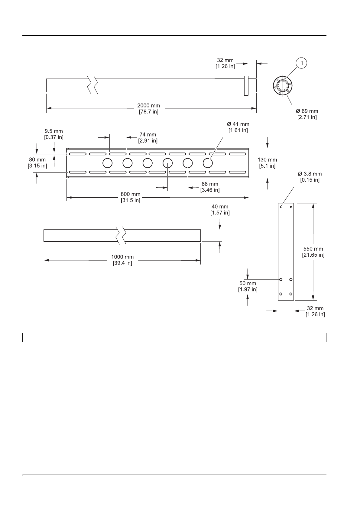
These installation instructions describe the installation of rail mounting hardware kit
LZX414.00.60000. Items supplied with the rail mounting hardware are shown in Figure 1 on
page 1. Figure 2 on page 2 shows the dimensions for the mounting hardware components.
DOC273.52.00087.Jul05
Figure 1 Items supplied with the rail mounting
1 Mounting rail HPS063 10 Fastening lug 19 Cap screw M8 x 40 mm (11x)
2 Supporting pipe (1 m) HRO307 11 Clamp (3x) 20 Washer for M10 (4x)
3 Mounting pipe (2 m) BRO075 12 Bracket, threaded AHH032 (3x) 21 Cable tie (3x)
4 Hardware set, LZY363 13 Bracket, unthreaded AHH033 (3x) 22 Spring locking pin (2x)
5 Base ATS010 14 Set of small parts LZY434 23 Cap screw M5 x 20 mm (10x)
6 Angle (2x) 15 Hex screw M8 x 120 mm (8x) 24 Spring washer for M5 (9x)
7 Clamping plate (2x) 16 Washer for M8 (12x) 25 Hex wrench 4 mm
8 Shim (3x) 17 Spring washer for M8 (19x) 26 Hex wrench 6 mm
9 Pipe cap (2x) 18 Nut M8 (16x), from LZY220
1
Page 4
Rail mounting hardware
Figure 2 Mounting hardware dimensions
1 Countersunk hole, clearance for M5 (6x)
2
Page 5
Installation dimensions
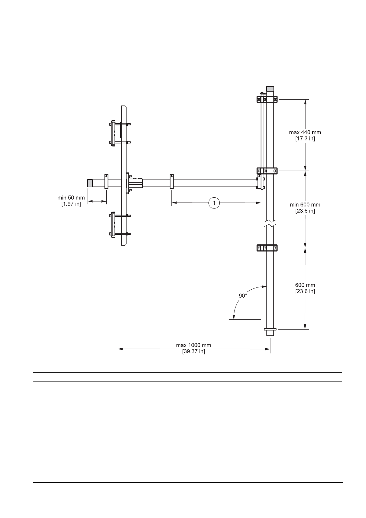
Figure 3 defines the position of the probe when the mounting pipe is in the service position
(see Placing the probe in the service position on page 12).
Rail mounting hardware
Figure 3 Installation dimensions
1 Position of the probe when mounting pipe is in the service position (dependent on the local situation).
3
Page 6
Rail mounting hardware
Selecting the installation location
Important note: Refer to the probe user manual for spe cific installation instructions. Note
all safety instructions and hazards.
Note: When selecting the installation location, always ensure there is safe access to all parts of the
system and that the probe can never hit the tank wall.
During the selection of the installation location, pay attention to:
• The load bearing capacity and strength of the railings (lever forces due to flow and
installation)
• The maximum cable and tubing lengths
Note: Refer to the probe user manual for operating instructions.
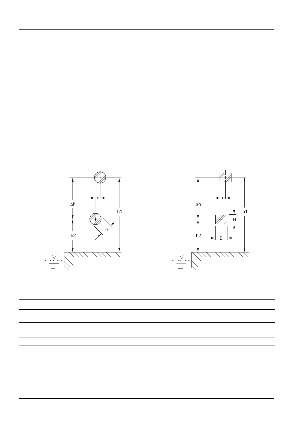
Railing specifications for mounting hardware
The rail mounting is designed for installation on round (Figure 4) or rectangular (Figure 5)
railing profiles. Table 1 contains information on the railing specifications for installation.
Note: Check other railing profiles for suitability to ensure adequate load bearing capacity.
Figure 4 Section drawing of round railing profile Figure 5 Section drawing of rectangular railing profile
Table 1 Rail mounting specifications
Round rail profile Rectangular rail profile
D: 25–75 mm (1.00–2.95 in.)
a: ≤ 25 mm (1.00 in.) a: ≤ 25 mm (1.00 in.)
h1: 850–1200 mm (33.50–47.25 in.) h1: 850–1200 mm (33.50–47.25 in.)
h2: 580–800 mm (22.80–31.50 in.) h2: 580–800 mm (22.80–31.50 in.)
Δh: 300–620 mm (11.80–24.40 in.) Δh: 300–620 mm (11.80–24.40 in.)
B: 40–90 mm (1.57–3.54 in.);
H: 40–68 mm (0.20–2.67 in.)
4
Page 7

Installing the rail mounting
1. Assemble the base and the two angles using four socket head cap screws
(M8 x 40 mm), washers for M10, spring washers for M8 and M8 nuts
(Figure 6 on page 6).
Fit the four socket head cap screws (M8 x 40 mm) and washers for M10 to the side of
the angle so that the holes in the angles are covered.
2. Loosely bolt the mounting rail and a clamping plate to the top railing using four screws
(M8 x 120 mm) with washers for M8, spring washers for M8 and M8 nuts
(Figure 7 on page 7). Do not tighten the screws until the entire rail mounting is aligned
and adjusted for height.
3. Loosely bolt the mounting rail and the second clamping plate to the bottom railing
using four screws (M8 x 120 mm) with washers for M8, spring washers for M8 and M8
nuts (Figure 7 on page 7).
• To change the installation height of the mounting rail, slide the screws along the
slots or use other slots.
• To change the mounting height of the base, fit the base higher or lower.
Rail mounting hardware
• For railings that are not vertically positioned or have different diameters, align the
mounting rail vertically by fitting shims between the railings and the mounting rail.
4. Fit a clamp to the middle and end of the supporting pipe using one M8 x 40 mm screw
and spring washer for each clamp (Figure 8 on page 7).
5. Bolt the fastening lug to the clamp on the end of the supporting pipe using four
M8 x 40 mm socket head cap screws, washers, spring washers and nuts
(Figure 9 on page 8).
6. Insert the supporting pipe through the base and fit the third clamp between the angles
using one M8 x 40 mm socket head cap screw and spring washer
(Figure 10 on page 8).
• Set the supporting pipe axial offset using the distance from the clamp between the
angles and the clamp in front of the base (see Figure 3 on page 3 and section
Placing the probe in the service position on page 12).
• Lock the supporting pipe to avoid twisting using the clamp between the angles.
Secure the probe on the vertical axis.
Important note: Fit the pipe cap on the end of the supporting pipe facing the user to
prevent leg injuries due the sharp pipe edges. The pipe can be shortened as needed
before fitting the pipe cap.
7. Bolt the retaining strap for the spring locking pin to one of the angles using an M5
socket head cap screw. Secure the supporting pipe against axial movement by
inserting the spring locking pin into a hole (Figure 11 on page 9).
8. Loosely bolt one of the three threaded brackets to one of the unthreaded brackets
using one M5 x 20 mm socket head cap screw and a spring washer. Push the bracket
onto the mounting pipe; pay attention to the bottom installation dimension (Figure 12
on page 10). Tighten the screws.
5
Page 8

Rail mounting hardware
9. Refer to the Filter Probe sc operating instructions to determine the installation position
for the two top brackets and loosely fit the brackets to the mounting pipe. Refer to
Figure 3 on page 3 for installation dimensions.
10. Slide the two top brackets over the mounting lug. Align the brackets and tighten
the screws.
11. Undo one of the screws on the top bracket and fit a strap for a spring locking pin
(Figure 13 on page 11). Tighten the screw.
12. Adjust the tank bracket and tighten all screws. Refer to Figure 3 on page 3 for
installation dimensions.
Figure 6 Fitting the base and angles
1 Socket head cap screw M8 x 40 mm 4 Base ATS010
2 Washer for M10 5 Spring washer for M8
3 Angle 6 Nut, M8
6
Page 9

Rail mounting hardware
Figure 7 Installing the mounting rail
1 Shim 3 Clamping plate
2 Mounting rail
Figure8Fittingtheclamps
1 Clamp 2 Supporting pipe
7
Page 10

Rail mounting hardware
Figure 9 Fitting the mounting lug
1 Clamp 2 Fastening lug
Figure 10 Fitting the supporting pipe, clamp and pipe cap
1 Pipe cap 3 Supporting pipe
2 Clamp
8
Page 11

Rail mounting hardware
Figure 11 Securing the supporting pipe
1 Spring locking pin 2 Angle
9
Page 12

Rail mounting hardware
Figure 12 Fitting the mounting pipe with brackets
1 Fastening lug 4 Bracket with thread
2 Bracket without thread 5 Brackets for measuring position
3 Mounting pipe 6 Bracket for service position
10
Page 13

Rail mounting hardware
Figure 13 Securing the mounting pipe
1 Spring locking pin 2 Fastening lug
Mounting the probe
1. Pull out the spring locking pin on the fastening lug. Remove the mounting pipe with
the brackets from the fastening lug.
2. Fit the probe to the mounting pipe and push the mounting pipe with the brackets back
onto the fastening lug.
3. Secure the tubing for the probe to the mounting pipe using cable ties.
4. Secure the mounting pipe on the fastening lug against floating upwards using the
spring locking pin.
5. Continue as described in the operating instructions for the Filter Probe and
the analyzer.
11
Page 14

Rail mounting hardware
Figure 14 Installed rail mounting
Placing the probe in the service position
1. Remove the spring locking pin from the fastening lug and pull the brackets with the
mounting pipe from the fastening lug.
2. Slide the mounting pipe onto the fastening lug using the bottom bracket
(Figure 15 on page 13).
3. Pull the spring locking pin out of the angle and pull the supporting pipe back to the
base until the clamp is in contact with the base.
12
Page 15

Rail mounting hardware
Figure 15 Filter Probe sc in the service position
Spare parts and accessories
Description Quantity Cat. No.
Rail Bracket Hardware Set 1 LZY363
Mounting Pipe (2 m) 1BRO075
Supporting Pipe 1 HRO307
Hardware Set 1LZY434
Base 1 ATS010
Bracket, complete 2 each LZX200
13
Page 16

Rail mounting hardware
14
Page 17

Warranty, liability and complaints
HACH LANGE GmbH warrants that the product supplied is free of
material and manufacturing defects and undertakes the obligation
to repair or replace any defective parts at zero cost.
The warranty period for instruments is 24 months. If a service
contract is taken out within 6 months of purchase, the warranty
period is extended to 60 months.
With the exclusion of the further claims, the supplier is liable for
defects including the lack of assured properties as follows: all those
parts that, within the warranty period calculated from the day of the
transfer of risk, can be demonstrated to have become unusable or
that can only be used with significant limitations due to a situation
present prior to the transfer of risk, in particular due to incorrect
design, poor materials or inadequate finish will be improved or
replaced, at the supplier's discretion. The identification of such
defects must be notified to the supplier in writing without delay,
however at the latest 7 days after the identification of the fault. If the
customer fails to notify the supplier, the product is considered
approved despite the defect. Further liability for any direct or
indirect damages is not accepted.
If instrument-specific maintenance and servicing work defined by
the supplier is to be performed within the warranty period by the
customer (maintenance) or by the supplier (servicing) and these
requirements are not met, claims for damages due to the failure to
comply with the requirements are rendered void.
Any further claims, in particular claims for consequential damages
cannot be made.
Consumables and damage caused by improper handling, poor
installation or incorrect use are excluded from this clause.
HACH LANGE GmbH process instruments are of proven reliability
in many applications and are therefore often used in automatic
control loops to provide the most economical possible operation of
the related process.
To avoid or limit consequential damage, it is therefore
recommended to design the control loop such that a malfunction in
an instrument results in an automatic change over to the backup
control system; this is the safest operating state for the environment
and the process.
15
Page 18

Contacts
HACH LANGE GMBH
Willstaetterstrasse 11
D-40549 Duesseldorf
Tel. +49 (0) 211- 52 88 - 0
Fax +49 (0) 211- 52 88 - 143
info@hach-lange.de
www.hach-lange.de
DR. BRUNO LANGE
GES. MBH
Industriestrasse 12
A-3200 Obergrafendorf
Tel. +43 (0) 2747 - 74 12
Fax +43 (0) 2747 - 42 18
info@hach-lange.at
www.hach-lange.at
HACH LANGE AB
Vinthundsvägen159A
SE-128 62 SKÖNDAL
Tel. +46 (0)8 7 98 05 00
Fax +46 (0)8 7 98 05 30
info@hach-lange.se
www.hach-lange.se
HACH LANGE LTD
Pacific Way
Salford
Manchester, M50 1DL
Tel. +44 (0)161 8 72 14 87
Fax +44 (0)161 8 48 73 24
info@hach-lange.co.uk
www.hach-lange.co.uk
DR. BRUNO LANGE AG
Juchstrasse 1
CH-8604 Hegnau
Tel. +41 (0)44 - 9 45 66 10
Fax +41 (0)44 - 9 45 66 76
info@hach-lange.ch
www.hach-lange.ch
HACH LANGE APS
Åkandevej 21
DK-2700 Brønshøj
Tel. +45 36 77 29 11
Fax +45 36 77 49 11
info@hach-lange.dk
www.hach-lange.dk
HACH LANGE LTD
Unit 1, Chestnut Road
Western Industrial Estate
IRL-Dublin 12
Tel. +353(0)1 4602522
Fax +353(0)1 4509337
info@hach-lange.ie
www.hach-lange.ie
HACH LANGE SA
Motstraat 54
B-2800 Mechelen
Tél. +32 (0)15 42 35 00
Fax +32 (0) 1541 61 20
info@hach-lange.be
www.hach-lange.be
HACH LANGE S.L.U.
C/Araba 45, Apdo. 220
E-20800 Zarautz/Guipúzcoa
Tel. +34 9 43 89 43 79
Fax +34 9 43 13 02 41
info@hach-lange.es
www.hach-lange.es
HACH LANGE
FRANCE S.A.S.
33, Rue du Ballon
F-93165 Noisy Le Grand
Tél. +33 (0)1 48 15 68 70
Fax +33 (0)1 48 15 80 00
info@hach-lange.fr
www.hach-lange.fr
DR. LANGE NEDERLAND
B.V.
Laan van Westroijen 2a
NL-4003 AZ Tiel
Tel. +31 (0)3 44 63 11 30
Fax +31 (0)3 44 63 11 50
info@hach-lange.nl
www.hach-lange.nl
HACH LANGE SP.ZO.O.
ul. Opolska 143 a
PL-52-013 Wroclaw
Tel. +48 71 3 42 10 -83
Fax +48 71 3 42 10-79
info@hach-lange.pl
www.hach-lange.pl
HACH LANGE S.R.L.
Via Riccione, 14
I-20156 Milano
Tel. +39 02 39 23 14-1
Fax +39 02 39 23 14-39
info@hach-lange.it
www.hach-lange.it
HACH LANGE S.R.L.
str. Aviator Teodor Iliescu nr.37
Sector 1
RO-011672, Bucuresti
Tel. +40 (0)21 2 08 95 78
Fax +40 (0)21 2 08 95 78
info@hach-lange.com
www.hach-lange.com
HACH LANGE S.R.O.
Lešanská 2a/1176
CZ-141 00 Praha 4
Tel. +420 272 12 45 45
Fax +420 272 12 45 46
info@hach-lange.cz
www.hach-lange.cz
HACH LANGE KFT.
Íves u. 2.
H-9027 Gy
Tel. +36 (06)96 511 400
Fax +36 (06)96 329 981
info@hach-lange.hu
www.hach-lange.hu
őr
HACH LANGE S.R.O.
Sabinovská 10
SK-821 02 Bratislava
Tel. +421 2 4820 9091
Fax +421 2 4820 9093
info@hach-lange.sk
www.hach-lange.sk
HACH LANGE
8, Kr. Sarafov str.
BG-1164 Sofia
Tel. +359 (0) 2 963 19 21
Fax +359 (0)2 866 04 47
info@hach-lange.com
www.hach-lange.com
HACH LANGE LDA
Av. do Forte nº8
Fracção M
P-2790-072 Carnaxide
Tel. +351 214 253 420
Fax +351 214 253 429
info@hach-lange.pt
www.hach-lange.pt
HACH LANGE SU
ANALİZ SİSTEMLERİ
LTD.ŞTİ.
Hilal Mah. 75. Sokak
Arman Plaza No: 9/A
TR-06550 Çankaya/ANKARA
Tel +90 (0)312 440 98 98
Faks +90 (0)312 442 11 01
bilgi@hach-lange.com.tr
www.hach-lange.com.tr
 Loading...