

Page 1

DOC023.52.03252
3798-S sc
Digital inductive conductivity sensor
User Manual
02/2013 Edition 2A
Page 2

© HACH LANGE GmbH, 2005, 2013. All rights reserved. Printed in Germany
Page 3

Table of contents
Section 1 Technical data............................................................................................................................................... 3
1.1 Technical data for the 3798-S sc conductivity sensor .............................................................................................. 3
Section 2 General information ..................................................................................................................................... 5
2.1 General handling instructions .................................................................................................................................... 5
2.2 Applications ............................................................................................................................................................... 5
2.3 Basic principles.......................................................................................................................................................... 5
2.4 Measuring principle ................................................................................................................................................... 6
Section 3 General safety instructions ......................................................................................................................... 7
3.1 Possible sources of hazards...................................................................................................................................... 7
3.2 Safety symbols .......................................................................................................................................................... 7
3.3 Electrical safety measures and fire prevention measures ......................................................................................... 8
3.4 Chemical safety measures ........................................................................................................................................ 9
3.5 Safety measures related to the flow of sample.......................................................................................................... 9
Section 4 Installation....................................................................................................................................................11
4.1 Connecting sensor cable ......................................................................................................................................... 11
4.2 Mechanical sensor installation................................................................................................................................. 12
4.2.1 Installation dimensions .................................................................................................................................. 12
Section 5 Operation..................................................................................................................................................... 15
5.1 Operating the sc controller ...................................................................................................................................... 15
5.2 Sensor setup ........................................................................................................................................................... 15
5.3 Sensor data logger .................................................................................................................................................. 15
5.4 The commands under SENSOR DIAG.................................................................................................................... 15
5.5 The commands under SENSOR SETUP ................................................................................................................ 16
5.6 Sensor calibration (conductivity) ............................................................................................................................. 17
5.6.1 Calibration in air (ZERO CAL)........................................................................................................................ 17
5.6.2 Calibration in air (ELECTRIC. SPAN) ............................................................................................................ 17
5.6.3 Calibration in the process (PROCESS SPAN)............................................................................................... 17
5.7 Adjusting the Temperature ...................................................................................................................................... 18
5.8 Calibrating two sensors simultaneously .................................................................................................................. 18
Section 6 Maintenance ................................................................................................................................................ 19
6.1 Maintenance schedule............................................................................................................................................. 19
6.2 Cleaning the sensor................................................................................................................................................. 19
Section 7 Faults, causes, rectification ...................................................................................................................... 21
7.1 Error messages ...................................................................................................................................................... 21
7.2 Warnings ................................................................................................................................................................ 21
7.3 Important service data ............................................................................................................................................. 22
Section 8 Spare parts .................................................................................................................................................. 23
Section 9 Warranty and liability ................................................................................................................................. 25
Section 10 Contact ...................................................................................................................................................... 27
Appendix A ModBUS Register Information ............................................................................................................. 29
1
Page 4

Table of contents
2
Page 5

Section 1 Technical data
1.1 Technical data for the 3798-S sc conductivity sensor
Materials Stainless steel metal housing, PEEK
Enclosure rating IP 68; stainless steel metal housing
Storage temperature
Sensor and controller
Cell constant K=2.35cm
Measuring range conductivity 250 µS/cm ... 2.5 S/
Temp. measuring range –5 °C ... 50 °C
Sensor operating temperature –20 °C ... 50 °C
Conductivity response time < 2 s; T90
Temp. response time <2min; T90
Conductivity measuring accuracy ± 1 % of the measured value displayed or ± 0.004 mS/
Temp. measuring accuracy ± 0.2 °C
Reproducibility < 0.2 %
Sensitivity ± 0.5 % of the end value of the measuring range
Sensor power < 7 W
Calibration
Max. immersion depth / pressure
for the sensor
–20 °C ... 60 °C; 95 % relative humidity, non-condensing
–1
cm
Zero value calibration in air.
Fixed value calibration with defined resistance or with standard solution
20 m / 2 bar
cm
Maximum flow speed 4 m/s
Sensor interface MODBUS
Sensor cable 10 m, hard wired, polyurethane
Sensor weight < 1 kg
Sensor dimensions (Ø × L) 43 × 370 mm
Fastening
• Immersed pipe
• Chain
Specifications are subject to change without notice.
3
Page 6

Technical data
4
Page 7

Section 2 General information
2.1 General handling instructions
Attention!
The sensor will only work correctly when the tip of the probe is completely
immersed in liquid. Ensure the tip of the probe always remains underwater
even when the water level fluctuates.
2.2 Applications
CAUTION!
Potential danger with contact with chemical/biological substances. Working
with chemical samples, standards and reagents can be dangerous. Make
yourself familiar with the necessary safety procedures and the correct
handling of the chemicals before use and read and follow all relevant safety
data sheets.
The sensor facilitates the straightforward and exact determination of the
conductivity of soiled to heavily soiled aqueous solutions. The system is specially
designed for use in municipal and industrial waste water.
2.3 Basic principles
Typical applications include
• Inlet and / or outlet of a sewage treatment plant
• Surface water if within the measuring range (> 250
Various different possible installations enable the system to be adapted to a very
wide range of conditions.
The electrolytic conductivity is the ability of a liquid to conduct an electrical current
(conductivity is the opposite of resistance). In metals, electrical currents are
passed by the movement of electrons, in liquids by the movement of ions. The
conductivity of a liquid depends on the one hand on the ionic concentration, on
the other hand on the temperature of the liquid.
To obtain the real conductivity of the liquid (in
measured
geometry of the probe and that is called the "cell constant or K" (
To be able to make a comparison between the measurements made at different
temperatures, the measurement must be converted to a reference temperature
(as a rule 25 °C).
1
/R (in S) must be multiplied by a coefficient that depends on the
C= K/R (S/cm)
S
/cm), the conductivity value
µS
/cm).
1
/
).
cm
5
Page 8
General information
1
4
5
2
3
6
7
This temperature-dependence, expressed in [% / °C], is termed the temperature
coefficient (α).
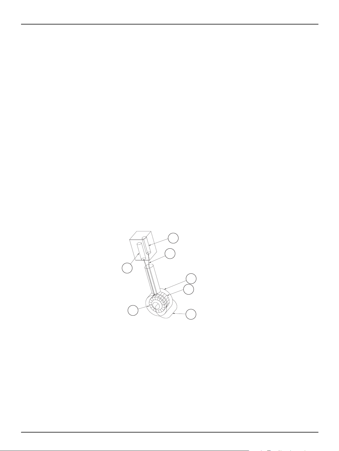
2.4 Measuring principle
C
= CT [1 + α (T – T
Tref
C
C
T
α : coefficient of the liquid temperature (
: conductivity adjusted to the reference temperature
Tref
: conductivity measured at T
T
: reference temperature (as a rule 25 °C)
ref
ref
)]
– 1
%
/°C)
The tip of the probe comprises two coils that are completely insulated from the
surrounding medium.
Primary coil
(transmitter):
An AC voltage is applied to the primary coil and produces an
alternating electromagnetic field in the surrounding liquid. This
magnetic field generates an electrical current in the liquid.
Secondary coil
(receiver):
The secondary coil determines the current produced by the
ion movements and calculates the conductivity of the liquid
from the current.
1. Receiver
2. Oscillator
3. Cable
4. Insulation
5. Receiver coil
6. Transmitter coil
7. Field line
The electrical insulation between liquid and sensor (magnetic coupling) has
advantages compared to the conventional method of using metal electrodes:
• no polarisation, for this reason the measuring range is larger
• high mechanical and chemical resistance
• possibility of taking measurements in soiled liquids
6
Page 9
Section 3 General safety instructions
Prior to unpacking, commissioning or operating the instrument, read all of this
manual.
Please pay particular attention to all instructions on hazards and safety. Otherwise
there is a risk of serious injury to the operator or damage to the instrument, or
pollution.
The sensor is only allowed to be installed and used as per the instructions in this
manual.
3.1 Possible sources of hazards
During the operation or calibration of the sensor, there exist the following sources
of hazards if the safety instructions are not observed:
• Potentially hazardous materials (buffer solutions, flow of sample)
In all circumstance observe the safety data sheets and the applicable health and
safety instructions.
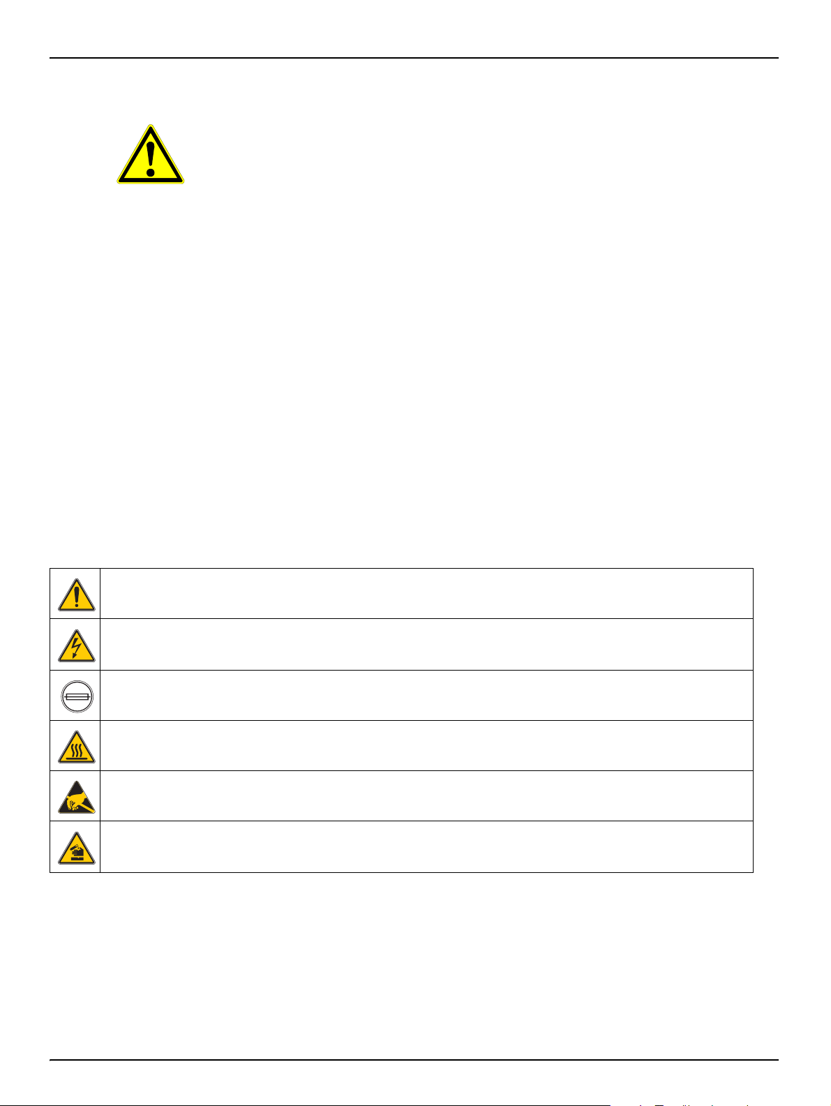
3.2 Safety symbols
This symbol, if present on the instrument, refers to information in the operating instructions on safe operation and / or
instructions that provide safety information.
This symbol, if present on a housing or a protective cover, identifies the risk of an electric shock (which may under
certain circumstances be fatal). Only personnel qualified for working on hazardous voltages are allowed to open the
enclosure or remove the protective cover.
This symbol, if present on the instrument, identifies the location of a fuse or current limit.
This symbol, if present on the instrument, identifies a part that may become hot and must not be touched without
taking precautions.
This symbol, if present on the instrument, indicates the presence of components that could be damaged by
electrostatic discharge. Appropriate precautions are to be taken.
This symbol, if present on the instrument, indicates the presence of dangerous chemical substances. Chemicals are
only allowed to be handled and maintenance on devices for supplying chemicals is only allowed to be performed by
personnel qualified and trained for working with chemicals.
All stickers and labels on the instrument are to be observed. Otherwise injuries,
pollution or damage to the instrument may occur.
7
Page 10
General safety instructions
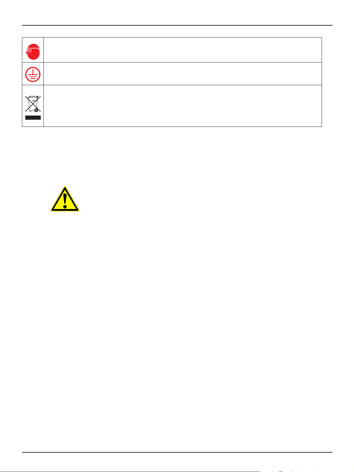
This symbol, if present on the instrument, indicates that safety glasses must be worn.
This symbol, if present on the instrument, identifies the location of the connection for the protective earth (ground).
As of 12 August 2005, electrical appliances marked with this symbol are no longer allowed to be disposed of in
Europe in unsorted household or industrial waste. As per the applicable regulations, from this date on consumers in
the EU must return old appliances to the manufacturer for disposal. This disposal is free of charge for the consumer.
Note: You can obt ain instructions on the correct disposal of all (marked and unmarked) electrical products that have
been supplied or manufactured by Hach-Lange from your local Hach-Lange sales office.
3.3 Electrical safety measures and fire prevention measures
The following safety instructions must be observed during the installation
and repair of cables that carry electrical power:
DANGER!
Sensors and controller are designed for compliance with the U.S. and
Canadian NEC as well as the European low voltage directive. No internal
electrical or electronic parts are allowed to be modified in any way, as this
could render the CE conformity void.
WARNING!
Only qualified experts may perform the tasks described in this section of the
manual, while adhering to all locally valid safety regulations.
• Prior to maintenance or repair of the instrument, isolate it from the power
supply.
• When making electrical connections, all applicable local and national
regulations are to be met.
• The use of earth leakage trips is strongly recommended.
• The instrument must be correctly earthed for correct operation.
8
Page 11

3.4 Chemical safety measures
CAUTION!
Reference and standard solutions are used for the calibration. Some of
these compounds are toxic or caustic.
Potential danger with contact with chemical/biological substances. Working
with chemical samples, standards and reagents can be dangerous. Make
yourself familiar with the necessary safety procedures and the correct
handling of the chemicals before use and read and follow all relevant safety
data sheets.
Physical contact with a calibration solution and inhalation of vapours from a
calibration solution are to be avoided or limited to an absolute minimum.
3.5 Safety measures related to the flow of sample
The assessment of the possible hazards from the individual sample flows is the
responsibility of the user. Suitable safety measures are to be taken to avoid any
unnecessary contact with a flow of sample of unknown composition in relation to
the hazards due to traces of chemicals, radiation or biological effects.
General safety instructions
9
Page 12

General safety instructions
10
Page 13

Section 4 Installation
1
2
3
4
5
6
4.1 Connecting sensor cable
You can connect the sensor cable to the controller very easily using the plug.
Retain the protective cap for the socket in case you need to remove the sensor in
the future. Connecting cables are available in the lengths 5 m, 10 m, 15 m, 20 m,
30 m and 50 m. From a length of 100 m a bus termination box must be integrated
(see Section 8 Spare parts).
Fig. 1 Connection of the sensor plug to the controller
Fig. 2 Sensor connector pin assignment
Number Description Cable colour
1+12 VDC brown
2Ground black
3 Data (+) blue
4 Data (–) white
5 Screen Screen (grey)
6Notch
11
Page 14

Installation
180 mm
1“ NPT
75 mm
215 mm
360 mm
410 mm
65 mm
57 mm
6 mm
4.2 Mechanical sensor installation
Notice!
The sensor will only work correctly when the tip of the probe is completely
immersed in liquid. Ensure the tip of the probe always remains underwater
even when the water level fluctuates.
CAUTION!
Potential danger with contact with chemical/biological substances. Working
with chemical samples, standards and reagents can be dangerous. Make
yourself familiar with the necessary safety procedures and the correct
handling of the chemicals before use and read and follow all relevant safety
data sheets.
Requirements
• Ensure the sensor does not collide with other instruments or objects in the
tank. In this way you will avoid damaging the sensor.
• Fasten the sensor to the nearest wall with a minimum spacing of 0.5 m.
4.2.1 Installation dimensions
12
Page 15

Fig. 3 Installation examples
Installation
1. Rim mounting chain bracket, PVC or stainless steel 2. Rim mounting immersed tube, PVC or stainless steel
13
Page 16

Installation
14
Page 17

Section 5 Operation
5.1 Operating the sc controller
The sensor can be operated with all sc controllers. Prior to using the sensor,
familiarise yourself with the principle of operation of your controller. Learn how to
navigate in the menus and run appropriate functions.
5.2 Sensor setup
When you connect the sensor for the first time, the serial number of the sensor is
displayed as the sensor name. You can change the sensor name as follows:
1. Open the MAIN MENU.
2. Choose SENSOR SETUP and accept.
3. Choose the related sensor and accept.
4. Choose CONFIGURE and accept.
5. Choose EDIT NAME and accept.
6. Edit the name and accept to return to the SENSOR SETUP menu.
In the same way complete your system configuration using the commands as per
table 5.5 "The commands under SENSOR SETUP".
5.3 Sensor data logger
A data memory and event memory per sensor are available via the sc controller.
While measured data are saved in the data memory at stipulated intervals, the
event memory collects numerous events such as configuration changes, alarms
and warning conditions. Both the data memory and the event memory can be
read out in CSV format. For information on how you can download the data,
please see the controller manual.
5.4 The commands under SENSOR DIAG
SENSOR DIAG
SELECT SENSOR (for several sensors)
ERROR LIST List of all errors that have occurred (see Section 7.1 "Error messages")
WARNING LIST
List of all warnings that have occurred
(see Section 7.2 "Warnings")
15
Page 18

Operation
5.5 The commands under SENSOR SETUP
SENSOR SETUP
SELECT SENSOR (for several sensors)
CALIBRATE
ZERO CAL
ELECTRIC. SPAN
PROCESS SPAN
PROCESS TEMP
CAL CONFIG
OUTPUT_MODE
CAL REMINDER
CORR FACTORS
SET CAL DEFLT Return to the factory settings after prompt for confirmation.
CONFIGURE
EDIT NAME Enter a 10-character name.
PARAMETERS Choose a parameter.
DEGREES C-F Choose between degrees Celsius or Fahrenheit.
T-COMPENSATION Choose between LINEAR and NONE.
T-SENSOR
AUTOMATIC
MANUAL Enter a value.
FILTER Enter a value.
LOG. DELAY
LOG INTERVAL Choose between the values available or DISABLED.
TEMP INTERVAL Choose between the values available or DISABLED.
MAINS FREQ. Enter the mains frequency.
SET DEFAULTS Returns to the factory settings after a prompt for confirmation.
DIAG/TEST
PROBE INFO Provides information on driver, software and serial number
CAL DATA Provides information on GAIN, Offset (T) and GAIN CORR.
SIGNALS Provides information on raw data measured.
COUNTERS Provides information on the operating time since the last calibration
TEST/MAINT Disable OUTPUT during test or maintenance
SERVICE Reset Service Counter
Eliminates sensor offset
See 5.6.1 "Calibration in air (ZERO CAL)".
Calibration with a defined resistance.
See 5.6.2 "Calibration in air (ELECTRIC. SPAN)".
Calibration with a reference solution.
See 5.6.3 "Calibration in the process (PROCESS SPAN)".
Calibration of the temperature.
See 5.7 "Adjusting the Temperature".
Choose between:
ACTIVE, output signal follows the input signal;
HOLD, last measured value and output signal are held;
TRANSFER, fixed value is output to the peripherals; and
CHOICE
You can set when the next calibration is to be performed. The
controller then automatically indicates when the next calibration is due.
Choose between
TEMP OFFSET,
GAIN CORR and
GAIN VALUE,
16
Page 19

5.6 Sensor calibration (conductivity)
The sensor has been permanently calibrated and operates with great enough
precision and stability that calibration is rarely necessary.
Calibrate the sensor
• as required (measured value outside the permitted tolerance,
see Section 7.3 "Important service data") or
• in accordance or agreement with the authorities.
5.6.1 Calibration in air (ZERO CAL)
1. On the controller, open the menu SENSOR SETUP => CALIBRATE => ZERO
CAL and accept.
2. Remove the sensor from the tank, clean and dry.
3. Accept.
Operation
4. Wait until the controller displays CAL COMPLETE.
5. Confirm that you have replaced the sensor in the sample flow and accept.
5.6.2 Calibration in air (ELECTRIC. SPAN)
1. Remove the probe from the flow of sample, clean and dry.
2. Connect a defined resistance (in range 5 Ohms - 5 kOhms) and accept to
continue.
3. Enter the value for the resistance and accept.
4. Wait until the value has stabilised.
5. Accept the value.
6. Replace the probe in the flow of sample and accept.
5.6.3 Calibration in the process (PROCESS SPAN)
1. Hold the cleaned probe in the solution and accept to continue.
2. Accept when the measured value has stabilised.
3. Enter the value and accept.
4. Replace the probe in the flow of sample and accept.
17
Page 20

Operation
5.7 Adjusting the Temperature
1. From the Main Menu, select SENSOR SETUP and confirm.
2. Highlight the appropriate sensor if more than one sensor is attached and
confirm.
3. Select CALIBRATE and confirm.
4. Select PROCESS TEMP and confirm.
5. Press ENTER when Stable, TEMP: XX.X is displayed. confirm to continue.
6. Adjust the Reading XX.X °C with the keypad and confirm.
7. CAL COMPLETE, OFFSET: X.X °C, confirm to continue.
8. MOVE PROBE TO PROCESS is displayed. Confirm.
5.8 Calibrating two sensors simultaneously
1. Start by calibrating the first sensor and when you arrive at the point at which
you are prompted to "PRESS ENTER WHEN STABLE".
2. Press the BACK key.
3. Select EXIT and press accept. The instrument returns to the display of the
measurements. The measured value for the sensor to be calibrated starts to
flash.
4. Start the calibration of the other sensor and when you again arrive at the point
at which you are prompted to "PRESS ENTER WHEN STABLE".
5. Press the BACK key.
6. Select EXIT and press accept. The instrument returns to the display of the
measurements. The measured values for both sensors start to flash.
7. To return to the calibration menu for the individual sensors, press the Menu
key, select SENSOR SETUP and accept. Choose the required sensor and
accept.
When calibration is complete, accept.
18
Page 21

Section 6 Maintenance
6.1 Maintenance schedule
The following table reflects experience and may, depending on the sector and
application, vary significantly from actual requirements.
Maintenance task 90 days annual
Clean sensor x
Check sensor for damage x
Calibration (if necessary)
You can set the calibration interval in the sensor setup. The controller then
reminds you when calibration is due.
6.2 Cleaning the sensor
If necessary as per
agreement with the
authorities
Clean the sensor with a jet of water. If there is still soiling present, use a soft,
damp cloth.
19
Page 22

Maintenance
20
Page 23

Section 7 Faults, causes, rectification
7.1 Error messages
Possible sensor errors are displayed by the controller.
Table 1: Error messages
Error displayed Cause Rectification
*****
SENSOR MISSING
FFFFFFFFFFFFF
TEMP TOO LOW Measured temperature < –5 °C
TEMP TOO HIGH
COND TOO LOW Conductivity < 100
COND TOO HIGH Conductivity > 500 mS/
RES. TOO LOW Resistance < 2
RES. TOO HIGH Resistance > 10 k
No communication with the
controller
No communication with the
controller
Measured temperature >
+100 °C
µS
/
cm
cm
Ω Please contact service.
Ω Please contact service.
Check the connection to the controller
Check the cable to the controller
Check the connection to the controller
Check the cable to the controller
Ensure that the
medium temperature is > –5 °C.
Ensure that the
medium temperature is < +100 °C.
Ensure that the
conductivity is > 100 µS/cm.
Ensure that the
conductivity is < 500 mS/cm.
7.2 Warnings
Possible warning messages are displayed by the controller.
Table 2: Warnings
Error displayed Cause Rectification
CAL TOO OLD
HUMIDITY BAG
The last calibration was more than
180 days ago.
The desiccant bag is more than
1000 days old.
Calibrate the sensor
Please contact service.
21
Page 24

Faults, causes, rectification
7.3 Important service data
Data Minimum Maximum
Electrical gain correction 95 % 105 %
CAL DATA
Signals
Counter
MODBUS STATS Number of communication errors 0 < 1 %
Temperature offset correction – 5 °C + 5 °C
Cell constant 2.50 2.00
Output voltage
Raw measured data – 1 % + 1 %
Desiccant bag
Operating time 1000 days
Measurement of fixed
resistance 1 k
Ω
Measured value 990
Ω 1010 Ω
22
Page 25

Section 8 Spare parts
3798-S sc, inductive conductivity sensor........................................................................................ LXV428.99.00001
User Manual ..................................................................................................................................DOC023.52.03252
Accessories for the conductivity sensor
Calibration set, electrical ................................................................................................................................ LZX985
Cable extension set (0.35 m).......................................................................................................................... LZX847
Cable extension set (5 m)............................................................................................................................... LZX848
Cable extension set (10 m)............................................................................................................................. LZX849
Cable extension set (15 m)............................................................................................................................. LZX850
Cable extension set (20 m)............................................................................................................................. LZX851
Cable extension set (30 m)............................................................................................................................. LZX852
Cable extension set (50 m)............................................................................................................................. LZX853
Termination box ............................................................................................................................................. 5867000
Immersed pipe, V4A....................................................................................................................... LZX914.99.01200
Immersed pipe, PVC ...................................................................................................................... LZX914.99.02200
Chain bracket, V4A..........................................................................................................................LZX914.99.11200
Chain bracket, PVC ........................................................................................................................ LZX914.99.12200
Immersed pipe set, V4A ................................................................................................................. LZX914.99.31200
Immersed pipe set, PVC................................................................................................................. LZX914.99.32200
U-bolt.............................................................................................................................................................. LZX959
Calibration set................................................................................................................................................. LZX985
Reference solutions
100 - 1000 µS/cm, 1l ........................................................................................................................25M3A2000-119
1000 - 2000 µS/cm, 1l ......................................................................................................................25M3A2050-119
2000 - 150,000 µS/cm, 1l .................................................................................................................25M3A2100-119
200000 - 300000 µS/cm, 1l ..............................................................................................................25M3A2200-119
23
Page 26

Spare parts
24
Page 27

Section 9 Warranty and liability
HACH LANGE GmbH warrants that the product supplied is free of material and
manufacturing defects and undertakes the obligation to repair or replace any
defective parts at zero cost.
The warranty period for instruments is 24 months. If a service contract is taken out
within 6 months of purchase, the warranty period is extended to 60 months.
With the exclusion of the further claims, the supplier is liable for defects including
the lack of assured properties as follows: all those parts that, within the warranty
period calculated from the day of the transfer of risk, can be demonstrated to have
become unusable or that can only be used with significant limitations due to a
situation present prior to the transfer of risk, in particular due to incorrect design,
poor materials or inadequate finish will be improved or replaced, at the supplier's
discretion. The identification of such defects must be notified to the supplier in
writing without delay, however at the latest 7 days after the identification of the
fault. If the customer fails to notify the supplier, the product is considered
approved despite the defect. Further liability for any direct or indirect damages is
not accepted.
If instrument-specific maintenance and servicing work defined by the supplier is to
be performed within the warranty period by the customer (maintenance) or by the
supplier (servicing) and these requirements are not met, claims for damages due
to the failure to comply with the requirements are rendered void.
Any further claims, in particular claims for consequential damages cannot be
made.
Consumables and damage caused by improper handling, poor installation or
incorrect use are excluded from this clause.
HACH LANGE GmbH process instruments are of proven reliability in many
applications and are therefore often used in automatic control loops to provide the
most economical possible operation of the related process.
To avoid or limit consequential damage, it is therefore recommended to design the
control loop such that a malfunction in an instrument results in an automatic
change over to the backup control system; this is the safest operating state for the
environment and the process.
25
Page 28

Warranty and liability
26
Page 29

Section 10 Contact
HACH Company
World Headquarters
P.O. Box 389
Loveland, Colorado
80539-0389 U.S.A.
Tel (800) 227-HACH
(800) -227-4224
(U.S.A. only)
Fax (970) 669-2932
orders@hach.com
www.hach.com
HACH LANGE GMBH
Willstätterstraße 11
D-40549 Düsseldorf
Tel. +49 (0)2 11 52 88-320
Fax +49 (0)2 11 52 88-210
info@hach-lange.de
www.hach-lange.de
HACH LANGE GMBH
Rorschacherstrasse 30a
CH-9424 Rheineck
Tel. +41 (0)848 55 66 99
Fax +41 (0)71 886 91 66
info@hach-lange.ch
www.hach-lange.ch
Repair Service in the
United States:
HACH Company
Ames Service
100 Dayton Avenue
Ames, Iowa 50010
Tel (800) 227-4224
(U.S.A. only)
Fax (515) 232-3835
HACH LANGE LTD
Pacific Way
Salford
GB-Manchester, M50 1DL
Tel. +44 (0)161 872 14 87
Fax +44 (0)161 848 73 24
info@hach-lange.co.uk
www.hach-lange.co.uk
HACH LANGE FRANCE
S.A.S.
8, mail Barthélémy Thimonnier
Lognes
F-77437 Marne-La-Vallée
cedex 2
Tél. +33 (0) 820 20 14 14
Fax +33 (0)1 69 67 34 99
info@hach-lange.fr
www.hach-lange.fr
Repair Service in Canada:
Hach Sales & Service
Canada Ltd.
1313 Border Street, Unit 34
Winnipeg, Manitoba
R3H 0X4
Tel (800) 665-7635
(Canada only)
Tel (204) 632-5598
Fax (204) 694-5134
canada@hach.com
HACH LANGE LTD
Unit 1, Chestnut Road
Western Industrial Estate
IRL-Dublin 12
Tel. +353(0)1 460 2522
Fax +353(0)1 450 9337
info@hach-lange.ie
www.hach-lange.ie
HACH LANGE NV/SA
Motstraat 54
B-2800 Mechelen
Tel. +32 (0)15 42 35 00
Fax +32 (0)15 41 61 20
info@hach-lange.be
www.hach-lange.be
Repair Service in
Latin America, the
Caribbean, the Far East,
Indian Subcontinent, Africa,
Europe, or the Middle East:
Hach Company World
Headquarters,
P.O. Box 389
Loveland, Colorado,
80539-0389 U.S.A.
Tel +001 (970) 669-3050
Fax +001 (970) 669-2932
intl@hach.com
HACH LANGE GMBH
Hütteldorfer Str. 299/Top 6
A-1140 Wien
Tel. +43 (0)1 912 16 92
Fax +43 (0)1 912 16 92-99
info@hach-lange.at
www.hach-lange.at
DR. LANGE NEDERLAND
B.V.
Laan van Westroijen 2a
NL-4003 AZ Tiel
Tel. +31(0)344 63 11 30
Fax +31(0)344 63 11 50
info@hach-lange.nl
www.hach-lange.nl
HACH LANGE APS
Åkandevej 21
DK-2700 Brønshøj
Tel. +45 36 77 29 11
Fax +45 36 77 49 11
info@hach-lange.dk
www.hach-lange.dk
HACH LANGE LDA
Av. do Forte nº8
Fracção M
P-2790-072 Carnaxide
Tel. +351 214 253 420
Fax +351 214 253 429
info@hach-lange.pt
www.hach-lange.pt
HACH LANGE KFT.
Vöröskereszt utca. 8-10.
H-1222 Budapest XXII. ker.
Tel. +36 1 225 7783
Fax +36 1 225 7784
info@hach-lange.hu
www.hach-lange.hu
HACH LANGE AB
Vinthundsvägen 159A
SE-128 62 Sköndal
Tel. +46 (0)8 7 98 05 00
Fax +46 (0)8 7 98 05 30
info@hach-lange.se
www.hach-lange.se
HACH LANGE SP. ZO.O.
ul. Krakowska 119
PL-50-428 Wrocław
Tel. +48 801 022 442
Zamówienia: +48 717 177 707
Doradztwo: +48 717 177 777
Fax +48 717 177 778
info@hach-lange.pl
www.hach-lange.pl
HACH LANGE S.R.L.
Str. Căminului nr. 3,
et. 1, ap. 1, Sector 2
RO-021741 Bucureşti
Tel. +40 (0) 21 205 30 03
Fax +40 (0) 21 205 30 17
info@hach-lange.ro
www.hach-lange.ro
HACH LANGE S.R.L.
Via Rossini, 1/A
I-20020 Lainate (MI)
Tel. +39 02 93 575 400
Fax +39 02 93 575 401
info@hach-lange.it
www.hach-lange.it
HACH LANGE S.R.O.
Zastrčená 1278/8
CZ-141 00 Praha 4 - Chodov
Tel. +420 272 12 45 45
Fax +420 272 12 45 46
info@hach-lange.cz
www.hach-lange.cz
HACH LANGE
8, Kr. Sarafov str.
BG-1164 Sofia
Tel. +359 (0)2 963 44 54
Fax +359 (0)2 866 15 26
info@hach-lange.bg
www.hach-lange.bg
HACH LANGE S.L.U.
Edificio Seminario
C/Larrauri, 1C- 2ª Pl.
E-48160 Derio/Vizcaya
Tel. +34 94 657 33 88
Fax +34 94 657 33 97
info@hach-lange.es
www.hach-lange.es
HACH LANGE S.R.O.
Roľnícka 21
SK-831 07 Bratislava –
Vaj nory
Tel. +421 (0)2 4820 9091
Fax +421 (0)2 4820 9093
info@hach-lange.sk
www.hach-lange.sk
HACH LANGE SU
ANALİZ SİSTEMLERİ
LTD.ŞTİ.
Ilkbahar mah. Galip Erdem
Cad. 616 Sok. No:9
TR-Oran-Çankaya/ANKARA
Tel. +90312 490 83 00
Fax +90312 491 99 03
bilgi@hach-lange.com.tr
www.hach-lange.com.tr
27
Page 30

Contact
HACH LANGE D.O.O.
Fajfarjeva 15
SI-1230 Domžale
Tel. +386 (0)59 051 000
Fax +386 (0)59 051 010
info@hach-lange.si
www.hach-lange.si
HACH LANGE OOO
Finlyandsky prospekt, 4A
Business Zentrum “Petrovsky
fort”, R.803
RU-194044, Sankt-Petersburg
Tel. +7 (812) 458 56 00
Fax. +7 (812) 458 56 00
info.russia@hach-lange.com
www.hach-lange.com
ΗΑCH LANGE E.Π.Ε.
Αυλίδος 27
GR-115 27 Αθήνα
Τηλ . +30 210 7777038
Fax +30 210 7777976
info@hach-lange.gr
www.hach-lange.gr
HACH LANGE D.O.O.
Ivana Severa bb
HR-42 000 Varaždin
Tel. +385 (0) 42 305 086
Fax +385 (0) 42 305 087
info@hach-lange.hr
www.hach-lange.hr
HACH LANGE MAROC
SARLAU
Villa 14 – Rue 2 Casa
Plaisance
Quartier Racine Extension
MA-Casablanca 20000
Tél. +212 (0)522 97 95 75
Fax +212 (0)522 36 89 34
info-maroc@hach-lange.com
www.hach-lange.ma
28
Page 31

Appendix A ModBUS Register Information
Table A-3 Sensor Modbus Registers
Tag Name Register # Data Type
Measurement mS/cm 40001 Float 2 R Conductivity in mS/cm
Measurement Ohm.cm 40003 Float 2 R Resistivity Ohm.cm
Measurement temperature 40005 Float 2 R Temperature
Measurement uScm 40007 Float 2 R Conductivity in uS/cm
Measurement S/m 40009 Float 2 R Conductivity in S/m
Measurement mS/m 40011 Float 2 R Conductivity in mS/m
Measurement KOhm.cm 40013 Float 2 R Resistivity KOhm.cm
Measurement Ohm.m 40015 Float 2 R Resistivity Ohm.m
Measurement Ohm.m (2) 40017 Float 2 R Resistivity Ohm.m2
AutoRange S/cm 40019 Integer 1 R Auto Ranging redirection
AutoRange S/m 40020 Integer 1 R Auto Ranging redirection of Sm
AutoRange Ohm.cm 40021 Integer 1 R Auto Ranging redirection of Ohm.cm
AutoRange Ohm.m 40022 Integer 1 R Auto Ranging of Ohm.m
measurement raw temperature 40023 Float 2 R Raw Temperature
Conductivity unit 40025 Integer 1 R Conductivity unit
Temperature unit 40026 Bit 1 R/W Temperature unit
Output Mode 40027 Integer 1 R/W OutputMode
Sensorname[0] 40028 Integer 1 R/W sensorname[0]
Sensorname[1] 40029 Integer 1 R/W sensorname[1]
Sensorname[2] 40030 Integer 1 R/W sensorname[2]
Sensorname[3] 40031 Integer 1 R/W sensorname[3]
Sensorname[4] 40032 Integer 1 R/W sensorname[4]
Sensorname[5] 40033 Integer 1 R/W sensorname[5]
Software Version (float) 40034 Float 2 R/W Software version
Driver Version (float) 40036 Float 2 R/W Driver version
Mains Frequency 50Hz 40038 Bit 1 R/W Main Frequency
Function code 40039 Integer 1 R/W Function Code
Next state 40040 Integer 1 R/W Next Step
Password 40041 Password 1 R/W Password
Serial number[1] 40042 Integer 1 R/W Serial number[0]
Serial number[2] 40043 Integer 1 R/W Serial number[1]
Serial number[3] 40044 Integer 1 R/W Serial number[2]
Conductivity parameter 40045 Bit 1 R/W &CMD_kunit
Temperature unit 40046 Bit 1 R/W &CMD_tunit
Offset correction 40047 Float 2 R/W Resistivity Offset
Electrical Calibration Resistance 40049 Float 2 R/W Resistivity Adjust vaue
Electrical Slope 40051 Float 2 R/W Electrical slope
Process Slope 40053 Float 2 R/W Process slope
Main Calibration Adjust Value 40055 Float 2 R/W Cal Conductivity Adjust Value
Second. Calibration Adjust Value 40057 Float 2 R/W Cal Temperature Adjust Value
Temporary Meas.[0] 40059 Float 2 R/W Temporary Measurement[0]
Temporary Meas.[1] 40061 Float 2 R/W Temporary Measurement[1]
Lengt
h
R/W Description
29
Page 32

ModBUS Register Information
Table A-3 Sensor Modbus Registers
Constant cell 40063 Float 2 R/W Constant cell
Temperature Compensation 40065 Bit 1 R/W Temperature Compensation
Coefficient Compensation 40066 Float 2 R/W Compensation Coefficient
Temperature Reference 40068 Float 2 R/W Temperature Reference
AutomaticTemperature 40070 Bit 1 R/W AutomaticTemperature
Manual Temperature 40071 Float 2 R/W Manual Temperature
Temperature Offset 40073 Float 2 R/W Temperature Offset
--- 40075 Integer 1 R/W &RS_tgMainMeas
--- 40076 Integer 1 R/W &RS_tgSecondMeas
--- 40077 Integer 1 R/W &RS_tgCalMainMeas
--- 40078 Integer 1 R/W &RS_tgCalSecondMeas
--- 40079 Integer 1 R/W &RS_tgCalMainAdjValue
--- 40080 Integer 1 R/W &RS_tgCalSecondAdjValue
--- 40081 Integer 1 R/W &RS_tgTemporary0
--- 40082 Integer 1 R/W &RS_tgTemporary1
--- 40083 Integer 1 R/W &RS_tgTempOffsetCorr
--- 40084 Integer 1 R/W &RS_tgTempRef
--- 40085 Integer 1 R/W &RS_tgTempManual
--- 40086 Integer 1 R/W Analogue Output Command
Serial Number String[0] 40087 Integer 1 R/W &RS_sn_string[0]
Serial Number String[2] 40088 Integer 1 R/W &RS_sn_string[2]
Serial Number String[4] 40089 Integer 1 R/W &RS_sn_string[4]
Serial Number String[6] 40090 Integer 1 R/W &RS_sn_string[6]
Serial Number String[8] 40091 Integer 1 R/W &RS_sn_string[8]
Serial Number String[8] 40092 Integer 1 R/W &RS_sn_string[10]
--- 40093 Float 2 R/W &MESS_OutputVoltage
Averaging 40095 Integer 1 R/W Averaging
--- 40096 Integer 1 R/W &MESS_cal_code
Delay from last Calibration 40097 Integer 1 R Delay from last Calibration
Time from Start up 40098 Integer 1 R Time from Start up
Time of Humidity Bag 40099 Integer 1 R Time of Humidity Bag
Conductivity Log Interval 40100 Integer 1 R Conductivity Log Interval
Temperature Log Interval 40101 Integer 1 R Temperature Log Interval
30
 Loading...