

Page 1

DOC023.52.00022.Jul05
3700 sc Inductive Conductivity Sensor
Operation Manual
Page 2

© HACH LANGE, 2005. All rights reserved. Printed in Germany.
Page 3

DOC023.52.00022.Jul05
3700sc Digital Conductivity Sensor
Opration Manual
© HACH LANGE, 2005. All rights reserved. Printed in Germany.
Page 4

Page 5

Table of Contents
Section 1 Specifications......................................................................................................................................... 5
Section 2 General Information ............................................................................................................................... 7
2.1 Safety Information ............................................................................................................................................... 7
2.1.1 Use of Hazard Information......................................................................................................................... 7
2.1.2 Precautionary Labels................................................................................................................................. 7
2.2 General Sensor Information ................................................................................................................................ 8
2.3 The Digital Gateway............................................................................................................................................ 8
2.4 Theory of Operation............................................................................................................................................ 8
Section 3 Installation .............................................................................................................................................. 9
3.1 Wiring the sc Sensor to the Digital Gateway....................................................................................................... 9
3.2 Connecting Digital Gateway to the sc Controller............................................................................................... 11
3.2.1 Attaching a sc Sensor with a Quick-connect Fitting ................................................................................ 11
3.3 Mounting the Digital Gateway ........................................................................................................................... 12
3.4 Installing the Sensor in the Sample Stream...................................................................................................... 13
Section 4 Operation .............................................................................................................................................. 15
4.1 Using the sc Controller...................................................................................................................................... 15
4.2 Sensor Setup ................................................................................................................................................... 15
4.3 Sensor Data Logging ........................................................................................................................................ 15
4.4 Sensor Status Menu.......................................................................................................................................... 15
4.5 Sensor Setup Menu ......................................................................................................................................... 15
4.6 Pressure and Elevation ..................................................................................................................................... 17
4.7 Calibration......................................................................................................................................................... 18
4.7.1 Preparing a Conductivity Reference Solution.......................................................................................... 18
4.7.2 Zero Cal................................................................................................................................................... 19
4.7.3 Sample Cal .............................................................................................................................................. 19
4.7.4 Cond Cal.................................................................................................................................................. 20
4.7.5 Concurrent Calibration of Two Sensors ................................................................................................... 20
4.8 Temperature Compensation.............................................................................................................................. 21
4.8.1 Entering Values into the Temperature Compensation Table.................................................................... 21
4.8.2 Entering Values into the Configuring Concentration Table ...................................................................... 21
4.8.3 Entering Values into the Configuring TDS Table ..................................................................................... 22
Section 5 Maintenance ......................................................................................................................................... 23
5.1 Maintenance Schedule ..................................................................................................................................... 23
5.2 Cleaning the Sensor ......................................................................................................................................... 23
Section 6 Troubleshooting ................................................................................................................................... 25
6.1 Error Codes....................................................................................................................................................... 25
6.2 Warnings........................................................................................................................................................... 25
Section 7 Replacement Parts and Accessories ................................................................................................. 27
7.1 Replacement Items, Accessories, and Reagent and Standards....................................................................... 27
Section 8 Warranty, liability and complaints ...................................................................................................... 29
8.1 Compliance Information .................................................................................................................................... 30
3
Page 6

Table of Contents
Section 9 Contact ................................................................................................................................................31
Appendix A Modbus Register Information ......................................................................................................32
4
Page 7
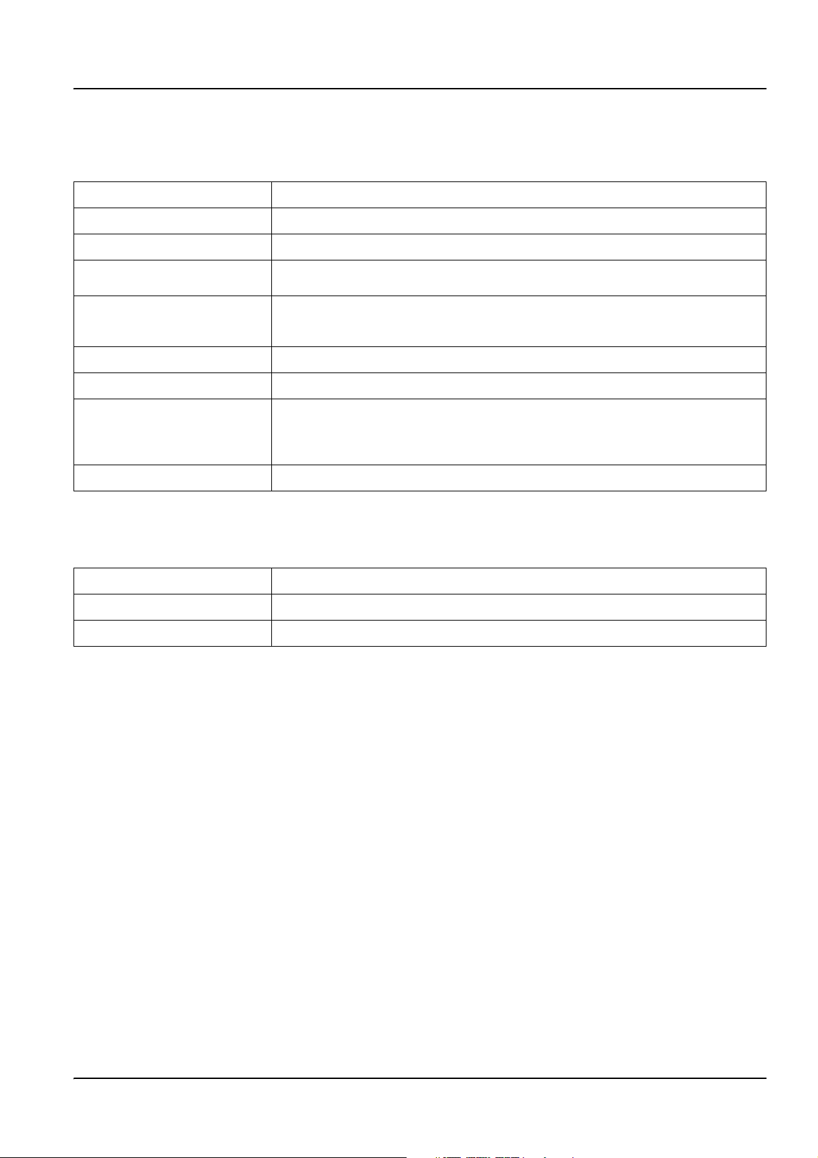
Section 1 Specifications
Specifications are subject to change without notice.
Table 1 Inductive Conductivity Probe Specifications
Components Corrosion-resistant materials, fully-immersible probe with 6 m (20 ft) cable
Conductivity Measuring Range 0.0 to 200.0; 0 to 2,000,000 microSiemens/cm
Measuring Range (Temperature) –10 to 200.0 °C (–14 to 392 °F) limited by sensor body material
Probe Operating Temperature
Pressure/Temperature Limits
(in pure water only)
Maximum Flow Rate 3 m (10 ft) per second
Temperature Compensator PT 1000 RTD
Sensor Cable
Probe Dimensions See Figure 1 and Figure 2 on page 8.
–10 to 200 °C (–14 to 392 °F); limited only by sensor body material and mounting
hardware
Polypropylene: 6.9 bar at 100 °C (100 psi at 212 °F) PVDF: 6.9 bar at 120 °C (100 psi at
248 °F) PEEK
(200 psi at 392 °F)
Polyproplyene and PVDF sensors: 5-conductor (plus two isolated shields) with XLPE
(cross-linked polyethylene) jacket; rated to 150 °C (302 °F; 20 ft (6 m) long PEEK
PFA Teflon
rated to 200 °C (392 °F); 6 m (20 ft) long.
®1
: 13.8 bar at 200 °C (200 psi at 392 °F) PFA Teflon®2: 13.8 bar at 200 °C
®
sensors: 5-conductor (plus two isolated shields) with Teflon®-coated jacket;
®
and
1
PEEK® is a registered trademark of ICI Americas, Inc.
2
Te f lo n® is a registered trademark of Dupont Co.
Table 2 Digital Gateway Specifications
Weight 145 g (5 oz)
Dimensions 17.5 x 3.4 cm (7 x 1
Operating Temperature –20 to 60 °C (–4 to 140 °F)
3
/8 in.)
5
Page 8

Specifications
6
Page 9
Section 2 General Information
2.1 Safety Information
Please read this entire manual before unpacking, setting up, or operating this equipment.
Pay attention to all danger and caution statements. Failure to do so could result in serious
injury to the operator or damage to the equipment.
To ensure that the protection provided by this equipment is not impaired, do not use or
install this equipment in any manner other than that specified in this manual.
2.1.1 Use of Hazard Information
DANGER
Indicates a potentially or imminently hazardous situation which, if not avoided,
could result in death or serious injury.
CAUTION
Indicates a potentially hazardous situation that may result in minor or moderate
injury.
Important Note: Information that requires special emphasis.
Note: Information that supplements points in the main text.
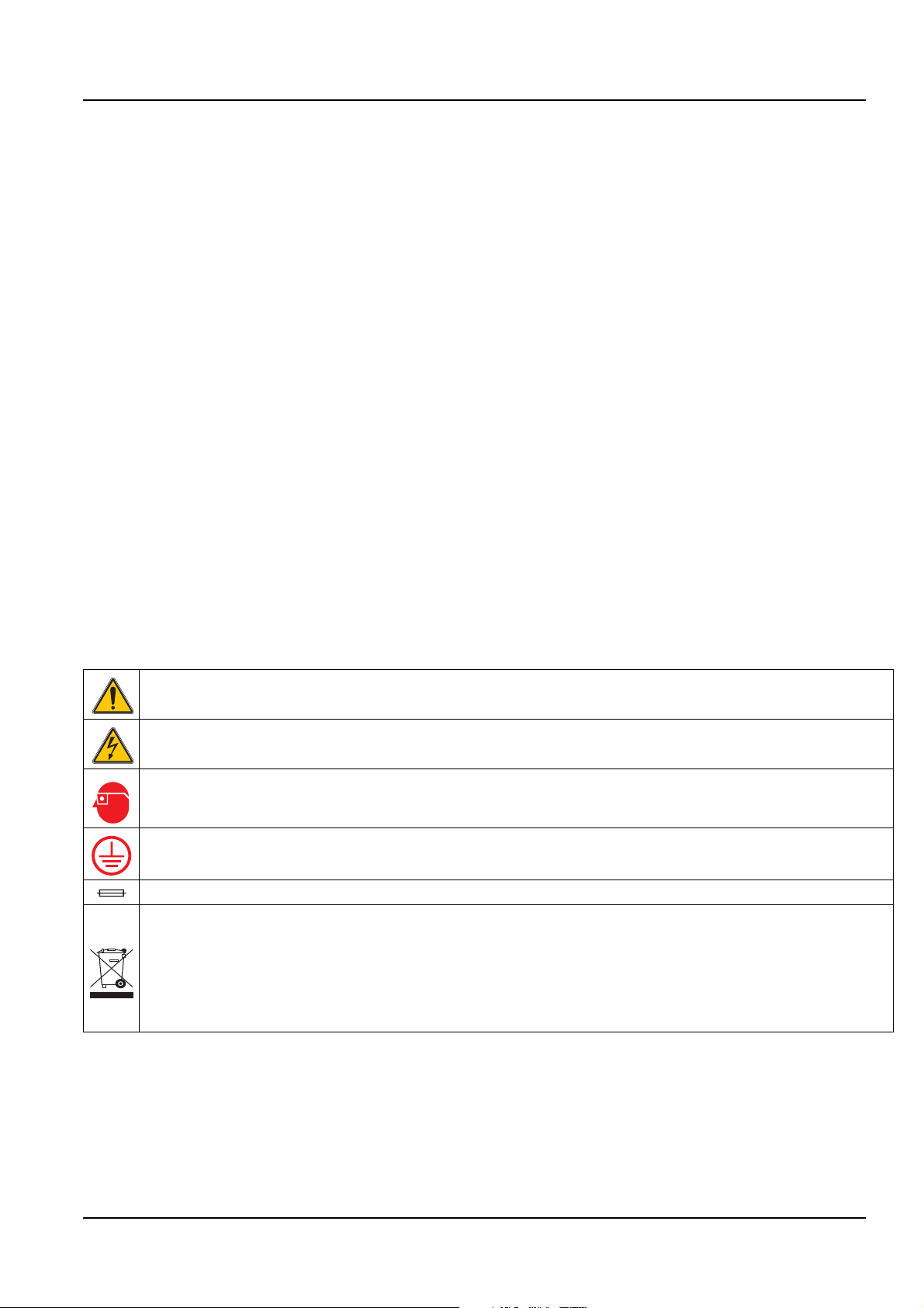
2.1.2 Precautionary Labels
Read all labels and tags attached to the instrument. Personal injury or damage to the
instrument could occur if not observed
This symbol, if noted on the instrument, references the instruction manual for operation
and/or safety information.
This symbol, when noted on a product enclosure or barrier, indicates that a risk of electrical shock and/or
electrocution exists.
This symbol, if noted on the product, indicates the need for protective eye wear.
This symbol, when noted on the product, identifies the location of the connection for Protective Earth
(ground).
This symbol, when noted on the product, identifies the location of a fuse or current limiting device.
Electrical equipment marked with this symbol may not be disposed of in European public disposal systems
after 12 August of 2005. In conformity with European local and national regulations (EU Directive
2002/96/EC), European electrical equipment users must now return old or end-of life equipment to the
Producer for disposal at no charge to the user.
Note: For all electrical products (marked or unmarked) which are supplied or produced by Hach-Lange, please contact
the local Hach-Lange sales office for instructions for proper disposal.
7
Page 10
General Information
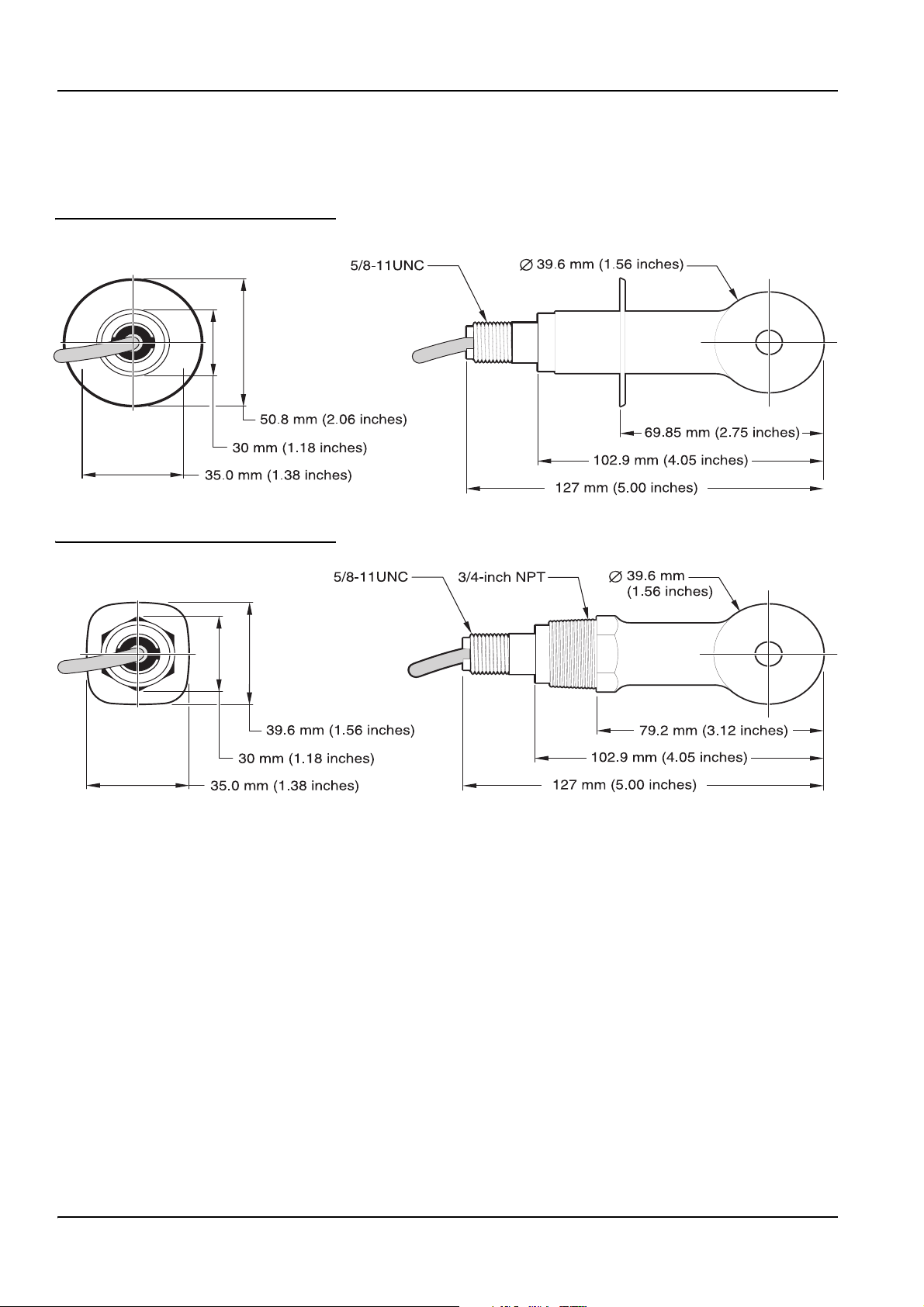
2.2 General Sensor Information
Optional equipment, such as mounting hardware for the probe, is supplied with
instructions for all user installation tasks.
Figure 1 Sanitary-style Sensor
Figure 2 Convertible-style Sensor
2.3 The Digital Gateway
The Digital Gateway was developed to provide a means to use existing analog sensors
with the new digital controllers. The gateway contains all the necessary software and
hardware to interface with the controller and output a digital signal.
2.4 Theory of Operation
Inductive conductivity measurements are made by passing an AC current through a
toroidal drive coil which induces a current in the electrolyte solution. This induced solution
current produces a current in a second toroidal coil. The amount of current induced in the
second coil is proportional to the solution conductivity.
The major advantage of toroidal conductivity is that the coils are not in contact with the
solution. Because the coils are isolated from the solution, oils and other contaminants in
moderate amounts do not interfere with the measurement. In addition, the coil housing can
be chosen to withstand corrosive environments which would quickly corrode traditional
sensors with metal electrodes.
8
Page 11

Section 3 Installation
DANGER
Only qualified personnel should conduct the tasks described in this section of the
manual.
The 3700sc Digital Conductivity Sensor can be used with any sc controller. Refer to the
controller manual for installation instructions.
The sc sensor should be wired to the digital gateway before connecting it to the sc
controller. The digital gateway is designed to provide a digital interface to the appropriate
digital controller. Refer to section 3.1 for more information.
3.1 Wiring the sc Sensor to the Digital Gateway
DANGER
Explosion hazard. Do not connect or disconnect equipment unless power has been
switched off or the area is known to be non-hazardous.
1. Route the cable from the sensor through the strain relief in the digital gateway then
properly terminate the wire ends (see Figure 3).
Note: Do not tighten the strain relief until the digital gateway is wired and the two halves are
threaded securely together.
2. Insert the wires as shown in Table 3 and Figure 3.
3. Make sure the O-ring is properly installed between the two halves of the digital
gateway and thread the two halves together. Hand tighten.
4. Tighten the strain relief to secure the sensor cable.
5. Connect the digital gateway to the controller.
9
Page 12
Installation
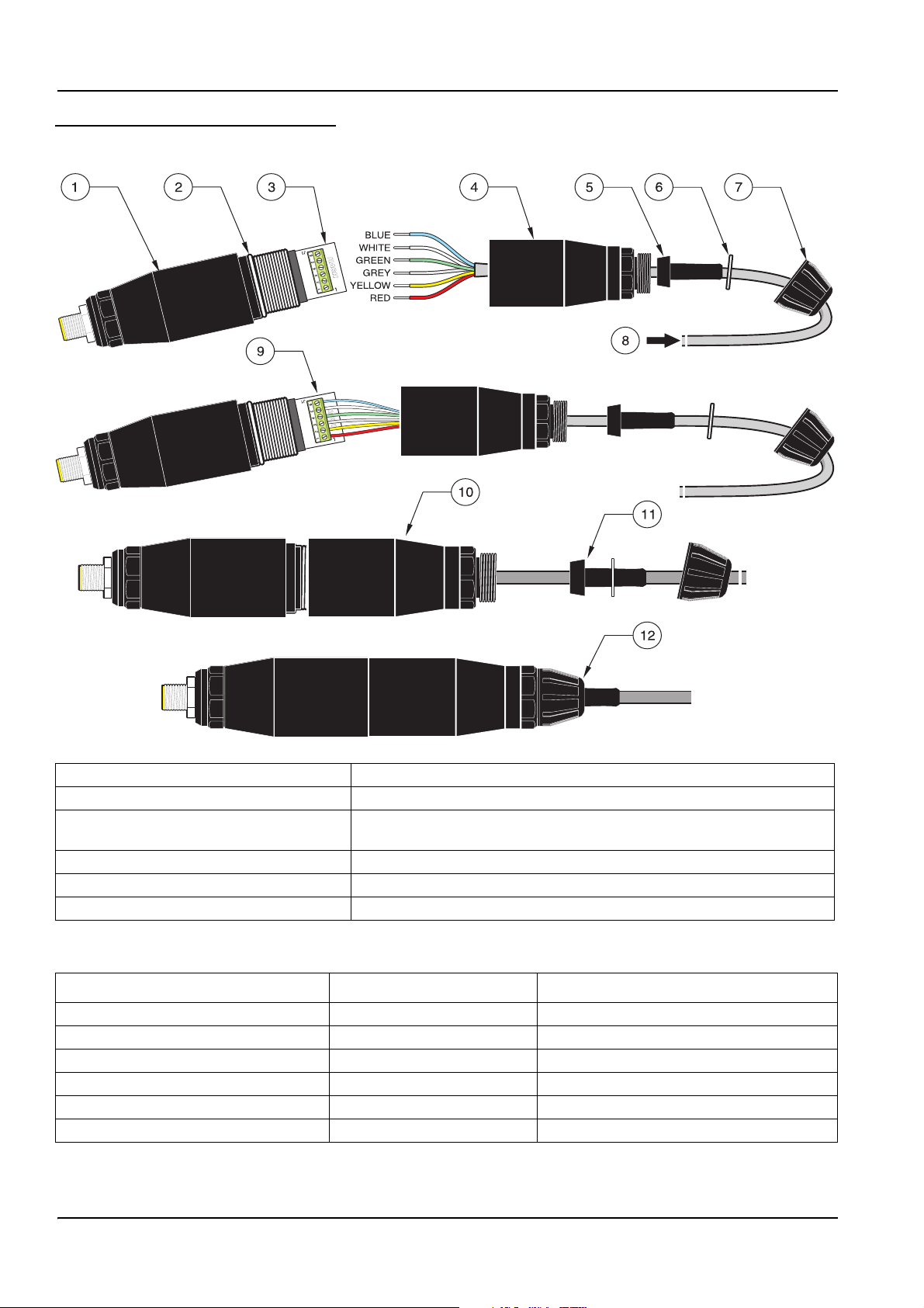
Figure 3 Wiring and Assembling the Digital Gateway
1. Digital gateway front 7. Nut, strain relief
2. O-ring 8. From sensor
3. Sensor wire connector 9. Insert wires into the connector according to Table 3. Use the included
2-mm screwdriver (Cat. No. 6134300) to secure connections.
4. Digital gateway back 10. Screw back of digital gateway onto front
5. Cable bushing 11. Push cable bushing and anti-rotation washer into back.
6. Anti-rotation washer 12. Fasten cord grip securely. Assembly is complete.
Table 3 Wiring the Digital Gateway
Sensor (wire color) Sensor Signal Digital Gateway Sensor Wire connector
Red Temp + 1
Yellow Temp – 2
Shield (grey) Shield 3
Green Sense 4
White Drive + 5
Blue Drive – 6
10
Page 13

3.2 Connecting Digital Gateway to the sc Controller
The digital gateway should be wired to the sensor before connecting to the controller.
3.2.1 Attaching a sc Sensor with a Quick-connect Fitting
The sensor cable is supplied with a keyed quick-connect fitting for easy attachment to the
controller (see Figure 4: Attaching the Sensor using the Quick-connect Fitting). Retain the
connector cap to seal the connector opening in case the sensor must be removed.
Optional extension cables may be purchased to extend the sensor cable length. If the total
cable length exceeds 100 m (300 ft), a termination box must be installed.
Note: Use of a load termination box other than Cat. No. 5867000 may result in a hazard.
Figure 4: Attaching the Sensor using the Quick-connect Fitting
Installation
Figure 5 Quick-connect Fitting pin assignment
5
4
3
Number Designation Wire Color
1+12 VDC Brown
2 Circuit Common Black
3 Data (+) Blue
4 Data (–) White
5 Shield Shield (grey wire in existing quick-disconnect fitting)
6Groove
6
1
2
11
Page 14

Installation
Table 4 Wiring the Sensor at Terminal Block J5
Terminal Number Terminal Designation Wire Color
1 Data (+) Blue
2 Data (–) White
3 Service Request No Connection
4 +12 V dc Brown
5 Circuit Common Black
6 Shield Shield (grey wire in existing quick disconnect fitting)
3.3 Mounting the Digital Gateway
The digital gateway is supplied with a mounting clip for mounting to a wall or other flat
surface. Digital gateway dimensions are shown in Figure 6. Use an appropriate fastener to
secure it to the wall. After the sensor is wired to the digital gateway and the two halves are
threaded together, place the mounting clip over the center of the digital gateway and
squeeze the clip together to secure. See Figure 7.
Figure 6 Digital Gateway Dimensions
34.29 mm
(1.35 inches)
184.15 mm (7.25 inches)
Figure 7 Mounting the Digital Gateway
1. Mounting clip 3. Hex nut, ¼-28
2. Screw, pan head, ¼-28 x 1.25-in.es 4. Mount clip, insert digital gateway, squeeze clip closed
12
Page 15

3.4 Installing the Sensor in the Sample Stream
Locate the sensor as close a possible to the instrument. The convertible style sensor may
be immersion mounted by threading it onto the end of a pipe of an appropriate length. It
may also be mounted in any standard 2-in. NPT pipe tee, weldolet, or pipe saddle using
the special union mount adapter. In addition, the sensor may be installed in a ball valve in
a pressurized or non-pressurized process pipe/vessel.
The sanitary-style sensor may be clamp-mounted for clean-in-place applications using a
sanitary clamp-type tee or ferrule and a heavy-duty clamp.
Examples of common sensor installations are shown in Figure 8 and dimension drawings
are shown in Figure 1 and Figure 2 on page 8. Refer to the instructions supplied with the
mounting hardware for installation specifics.
Figure 8 Sensor Installation Examples
Installation
1. Sanitary-style sensor sanitary clamp mounting 3. Convertible-style sensor immersion mounting
2. Convertible-style sensor union mounting 4. Convertible-style sensor ball valve mounting
13
Page 16

Installation
14
Page 17

Section 4 Operation
4.1 Using the sc Controller
Before using the sensor in combination with an sc controller make yourself familiar with
the operating mode of the controller. Refer to the controller user manual and learn how to
use and navigate the menu functions.
4.2 Sensor Setup
When a sensor is initially installed, the serial number of the sensor will be displayed as the
sensor name. To change the sensor name refer to the following instructions:
1. Select the Main Menu.
2. From the Main Menu, select SENSOR SETUP and confirm.
3. Select the appropriate sensor if more than one sensor is attached and confirm.
4. Select CONFIGURE and confirm.
5. Select EDIT NAME and edit the name. Confirm or cancel to return to the Sensor
Setup menu.
4.3 Sensor Data Logging
The sc controller provides one data log and one event log for each sensor. The data log
stores the measurement data at selected intervals. The event log stores a variety of events
that occur on the devices such as configuration changes, alarms, warning conditions, etc.
The data log and the event log can be read out in a CSV format. For downloading the logs
please refer to the controller user manual.
4.4 Sensor Status Menu
SELECT SENSOR
ERROR LIST—See section 6.1 on page 25.
WARNING LIST—See section 6.2 on page 25.
4.5 Sensor Setup Menu
CALIBRATE
SELECT SENSOR (if more than one sensor is attached)
ZERO
Perform a zero cal to remove sensor offset.
SAMPLE CAL
Perform a single point calibration.
COND CAL
After setting the reference temperature and slope, conduct a single-point calibration of the conductivity sensor.
TEMP ADJUST
Adjust the displayed temperature by up to ±15 °C.
DEFAULT SETUP
15
Page 18

Operation
4.5 Sensor Setup Menu (continued)
Resets all user-editable options to their factory-defaults.
CONFIGURE
EDIT NAME
Enter a 10-digit name in any combination of symbols and alpha or numeric characters.
SELECT MEASURE
Choose from Conductivity, Concentration, TDS, or Salinity. If Concentration is selected, the option to configure the
concentration settings is offered. Press the down arrow to Config Conc. Two concentration types are offered: Built-in and
User Defined. The Built-in menu offers an array of chemicals and concentrations to choose from.
COND UNITS
Choose from the displayed units (dependent on the parameter selected in the Select Measure menu)
TEMP UNITS
Select Celsius or Fahrenheit.
T–COMPENSATION
The factory default for temperature compensation is linear with a 2.00% per °C slope and a 25 °C reference temperature.
The default settings are appropriate for most aqueous solutions. The menu options are different depending on the
measurement that is selected in the Configure>Select Measure menu. The options are as follows:
NONE: No temperature compensation.
LINEAR: Recommended for most applications. Press
NATURAL WATER: Contact Technical Consulting Services for application specific information and assistance.
TEMP TABLE: Use to configure a temperature compensation table by entering up to 10 x-axis values and 10 y-axis values.
See section 4.8.1 on page 21 to enter values. Contact Technical Consulting Services for additional information and
assistance.
ENTER to change the slope or reference temperature.
LOG SETUP
Choose from Sensor Interval or Temp Interval. If the interval is enabled, choose from the displayed options to specify the
frequency to log the sensor or temperature reading. Default is Disabled.
AC FREQUENCY
Select 50 Hertz or 60 Hertz to specify the frequency to be excluded.
FILTER
Average the measurement over time by entering a number between 0–60. Default is 0 seconds.
TEMP ELEMENT
Select the temperature element type (100PT, 1000PT (default), or manual) then choose Select Factor to enter the specific
“T” Factor supplied with the sensor.
CAL DAYS
Number of days since the last calibration. Default notification at 60 days.
SENSOR DAYS
Number of days the sensor has been in operation. Default notification at 365 days.
DEFAULT SETUP
Reset the configure settings to the factory defaults.
16
Page 19

Operation
4.5 Sensor Setup Menu (continued)
DIAG/TEST
PROBE INFO
Display the entered name of the sensor, the sensor serial number, the software version number, and the sensor driver
version number.
CAL DATA
Displays the current offset correction and the date of the last calibration.
SIGNALS
SENSOR SIGNAL allows the user to set the sensor range and display the sensor ADC counts and TEMP ADC COUNTS
shows raw data for temperature ADC counts. Comparable to A/D counts.
COUNTERS
SENSOR DAYS displays the cumulative days the sensor has been in use and RESET SENSOR allows the sensor counter
to be reset to zero.
4.6 Pressure and Elevation
Note: If the barometric pressure from Table 5 is entered in the meter, the altitude entered in
combination with this value must be 0 feet.
Table 5 can be used to estimate the true barometric pressure at certain elevations. The
correspondence is based on the assumption that at sea level the barometric pressure is
760 mm Hg. After determining the barometric pressure from the table or obtaining it from a
local weather service, enter this value into the instrument.
Table 5 Elevation Barometric Pressure
Elevation in feet Barometric pressure in mm Hg Elevation in feet Barometric pressure in mm Hg
0 760 6000 613
500 746 6500 601
1000 733 7000 590
1500 720 7500 579
2000 708 8000 568
2500 695 8500 559
3000 683 9000 548
3500 671 9500 538
4000 659 10000 527
4500 647 10500 517
5000 635 11000 506
5500 624 — —
17
Page 20

Operation
4.7 Calibration
Calibration Methods When Measuring Conductivity:
• Sample Cal Method: Enter the known conductivity value of the sample
determined by laboratory analysis or a comparison reading.
• Conductivity Cal Method: Enter the known conductivity value of calibration
solution, and its linear % per °C and reference temperature values.
• Zero Cal Method: Enter the zero value (in air).
Calibration Methods When Measuring Percent Concentration:
• Process Cal (Conc) Method: Enter the known % concentration value of
calibration solution (ideally, process solution)
• Conductivity Cal Method: Enter the known conductivity value of calibration
solution, and its linear % per °C and reference temperature values.
• Sample Cal Method: Enter the known % concentration value of the sample
determined by laboratory analysis or a comparison reading.
Calibration Methods When Measuring TDS
• Process Cal (ppm) Method: Enter the known TDS ppm value of calibration
solution (ideally, process solution)
• Conductivity Cal Method: Enter the known conductivity value of calibration
solution, and its linear % per °C and reference temperature values.
• Sample Cal Method: Enter the known TDS ppm value of the sample determined
by laboratory analysis or a comparison reading.
4.7.1 Preparing a Conductivity Reference Solution
Add the listed grams of pure, dried NaCl to one liter of high-purity, deionized, CO2-free
water that is at a temperature of 25 °C.
Table 6 Conductivity Reference Solutions
Desired Solution Value
µS/cm mS/cm ppm (NaCl)*
200
500
1000
2000
3000
4000
5000
8000
10,000
20,000
50,000
100,000
0.20
0.5
01.00
2.00
3.00
4.00
5.00
8.00
10.00
20.00
50.00
100.00
100
250
500
1010
1530
2060
2610
4340
5560
11,590
31,950
72,710
Grams NaCl To Be Added
0.1
0.25
0.50
1.01
1.53
2.06
2.61
4.34
5.56
11.59
31.95
72.71
18
Page 21

4.7.2 Zero Cal
4.7.3 Sample Cal
Operation
A zero cal will mask interferences when mounting configurations are too close to objects
(including the pipe when mounted in-line) in the sample or sample stream.
1. From the Main Menu, select SENSOR SETUP and confirm.
2. Highlight the appropriate sensor if more than one sensor is attached and confirm.
3. Select CALIBRATE and confirm.
4. Select ZERO. Select the available Output Mode (Active, Hold, or Transfer) from the list
box and confirm.
5. Move the sensor to air and confirm to continue.
6. The zero calibration procedure will begin and “Wait to Stabilize” will be displayed.
The current value and temperature will be displayed. Confirm.
7. Return the sensor to the process.
1. From the Main Menu, select SENSOR SETUP and confirm.
2. Highlight the appropriate sensor if more than one sensor is attached and confirm.
3. Select CALIBRATE and confirm.
4. Select SAMPLE CAL. Select the available Output Mode (Active, Hold, or Transfer)
from the list box and confirm.
5. Move the probe to sample and confirm to continue.
6. Confirm
7. Return the sensor to the process.
when stable. A Sample Cal complete and the slope will be displayed.
19
Page 22

Operation
4.7.4 Cond Cal
1. From the Main Menu, select SENSOR SETUP and confirm.
2. Highlight the appropriate sensor if more than one sensor is attached and confirm.
3. Select CALIBRATE and confirm.
4. Select COND CAL. Select the available Output Mode (Active, Hold, or Transfer) from
the list box and confirm.
5. Select SET REF TEMP and confirm.
6. Select SET SLOPE and confirm.
7. Move the probe to the solution and confirm to continue.
8. Confirm when stable. A CAL Complete will be displayed and confirm.
9. Return the sensor to process.
4.7.5 Concurrent Calibration of Two Sensors
1. Begin a calibration on the first sensor and continue until “Wait to Stabilize”
is displayed.
2. Select LEAVE and confirm. The display will return to the Main Measurement screen
and the reading for both sensors will be flashing.
3. Begin the calibration for the second sensor and continue until “Wait to Stabilize”
is displayed.
4. Select LEAVE. The display will return to the Main Measurement screen and the
reading for both sensors will be flashing. The calibration for both sensors are now
running in the background.
5. To return to the calibration of either sensor select the Main Menu. Select Sensor Setup
and confirm. Select the appropriate sensor and confirm.
6. The calibration in progress will be displayed. Continue with the calibration.
20
Page 23

4.8 Temperature Compensation
The factory default for temperature compensation is linear with a 2.00% per °C slope and
a 25 °C reference temperature.
Change the type of sensor compensation by choosing Select Type. The available types
are as follows:
• NONE: No temperature compensation is applied.
• LINEAR: Recommended for most applications. Choose Config Linear and confirm
to access the menus for changing the slope or reference temperature.
• NATURAL WATER: Not available for TDS.
• TEMP TABLE: Use to configure a temperature compensation table by entering up
to 10 x-axis parameters and 10 y-axis parameters.
4.8.1 Entering Values into the Temperature Compensation Table
1. From the Main Menu, select SENSOR SETUP and confirm.
2. Highlight the appropriate sensor if more than one sensor is attached and confirm.
Operation
3. Select CONFIGURE and confirm.
4. Select T-COMPENSATION and confirm.
5. Select SELECT TYPE and confirm.
6. Select TEMP TABLE and confirm.
7. Select CONFIG TABLE and confirm.
8. Confirm again to edit the points.
4.8.2 Entering Values into the Configuring Concentration Table
If Concentration has been selected in the Select Measure menu, the user may choose to
enter values into the user defined table as follows:
1. From the Main Menu, select SENSOR SETUP and confirm.
2. Highlight the appropriate sensor if more than one sensor is attached and confirm.
3. Select SELECT MEASURE and change to Conc and confirm.
4. Select CONFIG CONC and confirm.
21
Page 24

Operation
5. Select SELECT TYPE. Select USER DEFINED or BUILT-IN and confirm.
If USER DEFINED is selected:
a. Select CONFIG TABLE and confirm.
b. Confirm again to edit the points.
If BUILT-IN is selected:
a. Choose from the list of built-in tables.
4.8.3 Entering Values into the Configuring TDS Table
If TDS has been selected in the Select Measure menu, the user may choose to enter
values into the user defined table as follows:
1. From the Main Menu, select SENSOR SETUP and confirm.
2. Highlight the appropriate sensor if more than one sensor is attached and confirm.
3. Select SELECT MEASURE and change to Conc and confirm.
4. Select CONFIG TDS and confirm.
5. Select SELECT FACTOR and confirm.
6. Choose NaCl or USER DEFINED. If NaCl is selected, not other configuration is
necessary.
If USER DEFINED is selected:
a. Select SET FACTOR and confirm.
b. Enter the value.
22
Page 25

Section 5 Maintenance
DANGER
Only qualified personnel should conduct the tasks described in this section of the
manual.
DANGER
Explosion hazard. Do not connect or disconnect equipment unless power has been
switched off or the area is known to be non-hazardous.
5.1 Maintenance Schedule
Maintenance Task 90 days
Clean the sensor
Inspect sensor for damage x
Calibrate Sensor (if required by regulatory agency) Per the schedule mandated by your regulatory agency.
1
Cleaning frequency is application dependent. More or less frequent cleaning will be appropriate in some applications.
1
x
5.2 Cleaning the Sensor
Clean the exterior of the sensor with a stream of clean water. If debris remains, use a wet
cloth or brush.
23
Page 26

Maintenance
24
Page 27

Section 6 Troubleshooting
6.1 Error Codes
When a sensor is experiencing an error condition, the sensor reading on
the measurement screen will flash and all relays and analog outputs associated with this
sensor will be held. The following conditions will cause the sensor reading to flash:
• Sensor calibration
• Loss of communication
Highlight the Sensor Diag menu and confirm. Highlight Errors and confirm to determine
the cause of the error. Errors are defined in Table 7.
Table 7 Error Codes
Displayed Error Definition Resolution
ADC FAILURE A/D conversion failed Contact customer service.
6.2 Warnings
A Sensor warning will leave all menus, relays, and outputs functioning normally, but will
cause a warning icon to flash on the right side of the display. Highlight the Sensor Diag
menu and confirm to determine the cause of the warning.
A warning may be used to trigger a relay and users can set warning levels to define the
severity of the warning. Errors are defined in Table 8.
Table 8 Warning Codes
Displayed Warning Definition Resolution
PROBE OUT
RANGE
TEMP OUT RANGE
FLASH FAILURE Cannot write flash memory. Contact customer service.
CAL REQUIRED Past the calibration days since last cal date. Calibrate system.
REPLACE
SENSOR
No probe connected or measurement reading is
out of range.
No temperature element connected or
temperature reading is out of range.
Past the total days of current sensor in use. New
sensor may need to be installed.
Verify the solution concentration and ensure that
the sensor in use has the correct measurement
range.
Verify that the solution temperature is between –20
to 200 °C.
Inspect sensor. If physically damaged or
malfunctioning, replace the sensor. Otherwise,
reset timer and allow sensor to remain in operation.
25
Page 28

Troubleshooting
26
Page 29

Section 7 Replacement Parts and Accessories
7.1 Replacement Items, Accessories, and Reagent and Standards
Item Quantity Catalog Number
Cable, sensor extension, 0,35 m each LZX847
Cable, sensor extension, 1 m each 6122400
Cable, sensor extension, 5 m each LZX848
Cable, sensor extension, 10 m each LZX849
Cable, sensor extension, 15 m each LZX850
Cable, sensor extension, 20 m each LZX851
Cable, sensor extension, 30 m each LZX852
Cable, sensor extension, 50 m each LZX853
Conductivity Reference Solution, 100–1000 µs/cm 1L 25M3A2000-119
Conductivity Reference Solution, 1000–2000 µs/cm 1L 25M3A2050-119
Conductivity Reference Solution, 2000–150,000 µs/cm 1L 25M3A2100-119
Conductivity Reference Solution, 200,000–300,000 µs/cm 1L 25M3A2200-119
Digital Gateway for Inductive Conductivity each 61208-00
Instruction manual, Inductive Conductivity System, English each DOC023.52.00022
27
Page 30

Replacement Parts and Accessories
28
Page 31

Section 8 Warranty, liability and complaints
HACH LANGE GmbH warrants that the product supplied is free of material and
manufacturing defects and undertakes the obligation to repair or replace any defective
parts at zero cost.
The warranty period for instruments is 24 months. If a service contract is taken out within 6
months of purchase, the warranty period is extended to 60 months.
With the exclusion of the further claims, the supplier is liable for defects including the lack
of assured properties as follows: all those parts that can be demonstrated to have become
unusable or that can only be used with significant limitations due to a situation present
prior to the transfer of risk, in particular due to incorrect design, poor materials or
inadequate finish will be improved or replaced, at the supplier's discretion. The
identification of such defects must be notified to the supplier in writing without delay,
however at the latest 7 days after the identification of the fault. If the customer fails to notify
the supplier, the product is considered approved despite the defect. Further liability for any
direct or indirect damages is not accepted.
If instrument-specific maintenance and servicing work defined by the supplier is to be
performed within the warranty period by the customer (maintenance) or by the supplier
(servicing) and these requirements are not met, claims for damages due to the failure to
comply with the requirements are rendered void.
Any further claims, in particular claims for consequential damages cannot be made.
Consumables and damage caused by improper handling, poor installation or incorrect use
are excluded from this clause.
HACH LANGE GmbH process instruments are of proven reliability in many applications
and are therefore often used in automatic control loops to provide the most economical
possible operation of the related process.
To avoid or limit consequential damage, it is therefore recommended to design the control
loop such that a malfunction in an instrument results in an automatic change over to the
backup control system; this is the safest operating state for the environment and the
process.
29
Page 32

Warranty, liability and complaints
8.1 Compliance Information
Hach Co. certifies this instrument was tested thoroughly, inspected and found to meet its
published specifications when it was shipped from the factory.
The Model sc100 Controller/sc1000 Controller with the Inductive Conductivity
Sensor has been tested and is certified as indicated to the following instrumentation
standards:
Product Safety
UL 61010A-1 (ETL Listing # 65454)
CSA C22.2 No. 1010.1 (ETLc Certification # 65454)
Certified by Hach Co. to EN 61010-1 Amds. 1 & 2 (IEC1010-1) per 73/23/EEC,
supporting test records by Intertek Testing Services.
Immunity
This equipment was tested for industrial level EMC per:
EN 61326 (EMC Requirements for Electrical Equipment for Measurement, Control
and Laboratory Use)
Company, certified compliance by Hach Company.
per 89/336/EEC EMC: Supporting test records by Hach
Emissions
Standards include:
IEC 1000-4-2:1995 (EN 61000-4-2:1995) Electrostatic Discharge Immunity (Criteria
B)
IEC 1000-4-3:1995 (EN 61000-4-3:1996) Radiated RF Electromagnetic Field
Immunity (Criteria A)
IEC 1000-4-4:1995 (EN 61000-4-4:1995) Electrical Fast Transients/Burst (Criteria B)
IEC 1000-4-5:1995 (EN 61000-4-5:1995) Surge (Criteria B)
IEC 1000-4-6:1996 (EN 61000-4-6:1996) Conducted Disturbances Induced by RF
Fields (Criteria A)
IEC 1000-4-11:1994 (EN 61000-4-11:1994) Voltage Dip/Short Interruptions (Criteria
B)
Additional Immunity Standard/s include:
ENV 50204:1996 Radiated Electromagnetic Field from Digital Telephones (Criteria A)
This equipment was tested for Radio Frequency Emissions as follows:
Per 89/336/EEC EMC: EN 61326:1998 (Electrical Equipment for measurement,
control and laboratory use—EMC requirements) Class “A” emission limits. Supporting
test records by Hewlett Packard, Fort Collins, Colorado Hardware Test Center (A2LA #
0905-01) and certified compliance by Hach Company.
Standards include:
30
EN 61000-3-2 Harmonic Disturbances Caused by Electrical Equipment
EN 61000-3-3 Voltage Fluctuation (Flicker) Disturbances Caused by Electrical
Equipment
Additional Emissions Standard/s include:
EN 55011 (CISPR 11), Class “A” emission limits
Page 33

Section 9 Contact
HACH LANGE GmbH
Willstätterstraße 11
D-40549 Düsseldorf
Tel. +49 (0) 211- 52 88 - 0
Fax +49 (0) 211- 52 88 - 143
info@hach-lange.de
www.hach-lange.de
DR. BRUNO LANGE
GES. MBH
Industriestraße 12
A-3200 Obergrafendorf
Tel. +43 (0) 2747 - 74 12
Fax +43 (0) 2747 - 42 18
info@hach-lange.at
www.hach-lange.de
DR. LANGE NEDERLAND B.V.
Laan van Westroijen 2a
NL-4003 AZ Tiel
Tel. +31(0)3 44 63 11 30
Fax +31(0)3 44 63 11 50
info@hach-lange.nl
www.hach-lange.nl
HACH LANGE LTD
Pacific Way
Salford
Manchester, M50 1DL
Tel. +44 (0)161 8 72 14 87
Fax +44 (0)161 8 48 73 24
info@hach-lange.co.uk
www.hach-lange.co.uk
DR. BRUNO LANGE AG
Juchstrasse 1
CH-8604 Hegnau
Tel. +41 (0)44- 9 45 66 10
Fax +41 (0)44- 9 45 66 76
info@hach-lange.ch
www.hach-lange.ch
HACH LANGE AB
Vinthundsvägen159A
SE-128 62 SKÖNDAL
Tel. +46 (0)8 7 98 05 00
Fax +46 (0)8 7 98 05 30
info@hach-lange.se
www.hach-lange.se
HACH LANGE
HACH SAS
33, Rue du Ballon
F-93165 Noisy Le Grand
Tél. +33 (0)1 48 15 68 70
Fax +33 (0)1 48 15 80 00
info@hach-lange.fr
www.hach-lange.fr
HACH LANGE SA
Motstraat 54
B-2800 Mechelen
Tél. +32 (0)15 42 35 00
Fax +32 (0)15 41 61 20
info@hach-lange.be
www.hach-lange.be
HACH LANGE A/S
Åkandevej 21
DK-2700 Brønshøj
Tel. +45 36 77 29 11
Fax +45 36 77 49 11
info@hach-lange.dk
www.hach-lange.dk
HACH LANGE S.L.U.
C/Araba 45, Apdo. 220
E-20800 Zarautz/Guipúzcoa
Tel. +34 9 43 89 43 79
Fax +34 9 43 13 02 41
info@hach-lange.es
www.hach-lange.es
HACH LANGE S.R.O.
Lešanská 2a/1176
CZ-141 00 Praha 4
Tel. +420 272 12 45 45
Fax +420 272 12 45 46
info@hach-lange.cz
www.hach-lange.cz
HACH LANGE SP.ZO.O.
ul. Opolska 143 a
PL-52-013 Wroclaw
Tel. +48 71 3 42 10-81
Fax +48 71 3 42 10-79
info@hach-lange.pl
www.hach-lange.pl
HACH LANGE S.R.O.
Sabinovská 10
SK-821 02 Bratislava
Tel. +421 2 4820 9091
Fax +421 2 4820 9093
info@hach-lange.sk
www.hach-lange.sk
HACH LANGE S.R.L.
Via Riccione, 14
I-20156 Milano
Tel. +39 02 39 23 14-1
Fax +39 02 39 23 14-39
info@hach-lange.it
www.hach-lange.it
HACH LANGE LDA
Rua dos Malhões,
Edif. D. Pedro I
P-2770-071 Paço D'Arcos
Tel. +351 210 00 1750
Fax +351 210 00 8140
info@hach-lange.pt
www.hach-lange.pt
31
Page 34

Appendix A Modbus Register Information
Table 9 Sensor Modbus Registers
Group Name Tag Name Register # Data Type Length R/W Description
Tags SensorMeasTag 40001 Integer 1 R Sensor Measurement Tag
Measurements DOMeas 40002 Float 2 R DO Measurement
Tags TempMeasTag 40004 Integer 1 R
Measurements TempDegCMeas 40005 Float 2 R Temperature Measurement
Configuration SensorName 40007 String 6 R/W Sensor Name
Tags FuncCode 40013 Integer 1 R/W Function Code tag
Tags NextState 40014 Integer 1 R/W Next State Tag
Configuration TempUnits 40015 Integer 1 R/W Temperature Units—C or F
Configuration Filter 40016 Integer 1 R/W Sensor Filter
Configuration TempElementType 40017 Integer 1 R/W Temperature Element Type
Tags TempUserValueTag 40018 Integer 1 R Temperature User Value Tag
Configuration TempUserDegCValue 40019 Float 2 R/W Temperature User Value
Configuration PressureUnits 40021 Integer 1 R/W Pressure Units
Configuration SalinityUnits 40022 Integer 1 R/W Salinity Units
Tags PressureTag 40023 Integer 1 R Pressure Tag
Configuration Pressure 40024 Float 2 R/W Pressure
Tags SalinityTag 40026 Integer 1 R Salinity Units
Configuration Salinity 40027 Float 2 R/W Salinity
Configuration MeasUnits 40029 Integer 1 R/W Measurement Units
Calibration OutputMode 40030 Integer 1 R/W Output Mode
Calibration CalLeave 40031 Integer 1 R/W Cal Leave Mode
Calibration CalAbort 40032 Integer 1 R/W Cal Abort Mode
Tags CalEditValueTag 40033 Integer 1 R Cal Edit Value Tag
Calibration CalEditDOValue 40034 Float 2 R/W Cal Edit Value
Diagnostics SoftwareVersion 40036 String 6 R Software Version
Diagnostics SerialNumber 40042 String 6 R Serial Number
Diagnostics CalQValue 40048 Float 2 R DO Cal Q Value
Calibration CalCode 40050 Integer 1 R Cal Code
Configuration SensorLogInterval 40051 Integer 1 R/W Sensor Data Log Interval
Configuration TempLogInterval 40052 Integer 1 R/W
Diagnostics DOmV 40053 Float 2 R DO mV
Diagnostics ProdDate 40055 Date 2 R/W Production Date
Diagnostics LastCalDate 40057 Date 2 R Last Calibration Date
Diagnostics SensorDays 40059 Integer 1 R Sensor Run\ning Days
Configuration RejectFrequency 40060 Integer 1 R/W Reject Frequency
Diagnostics DeviceDriver 40061 String 5 R Device Driver
Configuration CalWarningDays 40066 Integer 1 R/W Calibration Warning Days
Configuration SensorWarningDays 40067 Integer 1 R/W Sensor Warning Days
Tags SensorMeasTag 40001 Integer 1 R Sensor Measurement Tag
Measurements DOMeas 40002 Float 2 R DO Measurement
Tags TempMeasTag 40004 Integer 1 R
Temperature Measurement
Ta g
Temperature Data Log
Interval
Temperature Measurement
Ta g
32
Page 35

Modbus Register Information
Table 9 Sensor Modbus Registers (continued)
Group Name Tag Name Register # Data Type Length R/W Description
Measurements TempDegCMeas 40005 Float 2 R Temperature Measurement
Configuration SensorName 40007 String 6 R/W Sensor Name
Tags FuncCode 40013 Integer 1 R/W Function Code tag
Tags NextState 40014 Integer 1 R/W Next State Tag
Configuration TempUnits 40015 Integer 1 R/W Temperature Units—C or F
Configuration Filter 40016 Integer 1 R/W Sensor Filter
Configuration TempElementType 40017 Integer 1 R/W Temperature Element Type
Tags TempUserValueTag 40018 Integer 1 R Temperature User Value Tag
Configuration TempUserDegCValue 40019 Float 2 R/W Temperature User Value
Configuration PressureUnits 40021 Integer 1 R/W Pressure Units
Configuration SalinityUnits 40022 Integer 1 R/W Salinity Units
Tags PressureTag 40023 Integer 1 R Pressure Tag
Configuration Pressure 40024 Float 2 R/W Pressure
Tags SalinityTag 40026 Integer 1 R Salinity Units
Configuration Salinity 40027 Float 2 R/W Salinity
Configuration MeasUnits 40029 Integer 1 R/W Measurement Units
Calibration OutputMode 40030 Integer 1 R/W Output Mode
Calibration CalLeave 40031 Integer 1 R/W Cal Leave Mode
Calibration CalAbort 40032 Integer 1 R/W Cal Abort Mode
Tags CalEditValueTag 40033 Integer 1 R Cal Edit Value Tag
Calibration CalEditDOValue 40034 Float 2 R/W Cal Edit Value
Diagnostics SoftwareVersion 40036 String 6 R Software Version
Diagnostics SerialNumber 40042 String 6 R Serial Number
Diagnostics CalQValue 40048 Float 2 R DO Cal Q Value
Calibration CalCode 40050 Integer 1 R Cal Code
Configuration SensorLogInterval 40051 Integer 1 R/W Sensor Data Log Interval
Configuration TempLogInterval 40052 Integer 1 R/W
Diagnostics DOmV 40053 Float 2 R DO mV
Diagnostics ProdDate 40055 Date 2 R/W Production Date
Diagnostics LastCalDate 40057 Date 2 R Last Calibration Date
Diagnostics SensorDays 40059 Integer 1 R Sensor Run\ning Days
Configuration RejectFrequency 40060 Integer 1 R/W Reject Frequency
Diagnostics DeviceDriver 40061 String 5 R Device Driver
Configuration CalWarningDays 40066 Integer 1 R/W Calibration Warning Days
Configuration SensorWarningDays 40067 Integer 1 R/W Sensor Warning Days
Tags SensorMeasTag 40001 Integer 1 R Sensor Measurement Tag
Measurements DOMeas 40002 Float 2 R DO Measurement
Temperature Data Log
Interval
33
Page 36

Modbus Register Information
34
Page 37

Index
C
Calibration ..............................................................17, 18
One Point ............................................................... 20
Cleaning
Controller ............................................................... 23
Sensor.................................................................... 23
Compliance Information................................................ 31
Configuring
System ................................................................... 15
D
Display.......................................................................... 15
E
Error Codes .................................................................. 25
M
Maintenance Schedule ................................................. 23
P
Parts
Replacement.......................................................... 27
S
Safety Information .......................................................... 7
Sensor
Dimensions ............................................................ 13
Installation.............................................................. 13
Specifications ................................................................. 5
T
Theory of Operation ....................................................... 8
W
Warnings ...................................................................... 25
Z
Zero Cal........................................................................ 19
35
Page 38

Index
36
 Loading...