

Page 1

DOC023.52.03249.Jun05
3400 sc Digital Conductivity
Analysis Sensors
User Manual
Page 2

© HACH LANGE GmbH, 2005. All rights reserved. Printed in Germany.
Page 3

DOC023.52.03249.Jun05
3400 sc Digital Conductivity
Analysis System
User Manual
© HACH LANGE GmbH, 2005. All rights reserved. Printed in Germany.
Page 4

Page 5

Table of Contents
Section 1 Specifications......................................................................................................................................... 3
Section 2 General Information ............................................................................................................................... 7
2.1 Safety Information ............................................................................................................................................... 7
2.1.1 Use of Hazard Information......................................................................................................................... 7
2.1.2 Precautionary Labels................................................................................................................................. 7
2.2 General Sensor Information ................................................................................................................................ 8
2.3 The Digital Gateway.......................................................................................................................................... 10
2.4 Theory of Operation.......................................................................................................................................... 10
Section 3 Installation ............................................................................................................................................ 11
3.1 Connecting the Sensor to an sc Controller ....................................................................................................... 11
3.1.1 Attaching a sc Sensor with a Quick-connect Fitting ................................................................................ 11
3.2 Using the Digital Gateway................................................................................................................................. 12
3.2.1 Wiring the sc Sensor to the Digital Gateway ........................................................................................... 12
3.2.2 Mounting the Digital Gateway.................................................................................................................. 14
3.3 Installing the Sensor in the Sample Stream...................................................................................................... 15
Section 4 Operation .............................................................................................................................................. 17
4.1 Using an sc Controller....................................................................................................................................... 17
4.2 Sensor Setup ................................................................................................................................................... 17
4.3 Sensor Data Logging ........................................................................................................................................ 17
4.4 SENSOR STATUS Menu................................................................................................................................... 17
4.5 SENSOR SETUP Menu .................................................................................................................................... 17
4.6 Calibration......................................................................................................................................................... 19
4.6.1 Zero Cal................................................................................................................................................... 19
4.6.2 One Point Sample Calibration ................................................................................................................. 20
4.6.3 Concurrent Calibration of Two Sensors ................................................................................................... 20
4.6.3.1 Preparing Conductivity Reference Solutions.................................................................................. 21
4.7 Adjusting the Temperature ................................................................................................................................ 21
Section 5 Maintenance ......................................................................................................................................... 23
5.1 Maintenance Schedule ..................................................................................................................................... 23
5.2 Cleaning the Sensor ......................................................................................................................................... 23
Section 6 Troubleshooting ................................................................................................................................... 25
6.1 Error Codes ...................................................................................................................................................... 25
6.2 Warnings .......................................................................................................................................................... 25
6.3 General Troubleshooting .................................................................................................................................. 26
6.4 Checking Sensor Operation .............................................................................................................................. 26
6.4.1 Sensors without the Integral Junction Box............................................................................................... 26
6.4.2 Analog or External Digital Gateway Sensors........................................................................................... 27
6.4.3 Sensor Linearity Check ........................................................................................................................... 28
Section 7 Replacement Parts ............................................................................................................................... 29
7.1 Replacement Items and Accessories................................................................................................................ 29
Section 8 Warranty, liability and complaints ...................................................................................................... 31
8.1 Compliance Information .................................................................................................................................... 32
I
Page 6

Table of Contents
Section 9 Adresses .............................................................................................................................................33
Appendix A Additional information for series 34xx sensors ............................................................................35
A.1 Additional information for series 3410 ... 3412 sensors ....................................................................................35
A.1.1 Technical data for the 43410 ... 3412 sensors ........................................................................................35
A.1.2 Installation of the sensors........................................................................................................................35
A.1.3 Installation of the sensor in the flow of sample........................................................................................35
A.2 Additional information for series 3415 ... 3417 sensors ....................................................................................37
A.2.1 Technical data for the 3415 ... 3417 sensors ..........................................................................................37
A.2.2 Installation of the sensors........................................................................................................................37
A.2.3 Installation of the sensor in the flow of sample........................................................................................37
A.3 Additional information for series 3494 sensors .................................................................................................39
A.3.1 Technical data for the 3494 sensors .......................................................................................................39
A.3.2 Installation of the sensors........................................................................................................................39
A.3.3 Installation of the sensor in the flow of sample........................................................................................39
A.4 Digital gateway..................................................................................................................................................41
A.5 Accessories.......................................................................................................................................................42
A.5.1 Technical data for the bypass chambers.................................................................................................42
A.6 Spare parts and accessories.............................................................................................................................44
Appendix B Modbus Register Information .........................................................................................................45
II
Page 7

Section 1 Specifications
Specifications are subject to change without notice.
Table 1: 3400sc-series Conductivity Probe Specifications
Components Corrosion-resistant materials, fully-immersible probe with 10 m (30 ft) cable
Measuring Range (Conductivity) See Table 3: " Sensor Cell Constants and Measuring Ranges" on page 5
Measuring Range (Resistivity) See Table 3: " Sensor Cell Constants and Measuring Ranges" on page 5
Measuring Range (TDS) See Table 3: " Sensor Cell Constants and Measuring Ranges" on page 5
Measuring Range (Temperature) –20.0 to 200.0 °C (–4.0 to 392.0 °F)
Operating Temperature/Humidity –20 to 60 °C (–4 to 140 °F); 0–95% relative humidity, non-condensing
Storage Temperature/Humidity –30 to 70 °C (–22 to 158 °F); 0–95% relative humidity, non-condensing
Response Time 90% of reading within 30 seconds of step change
Measurement Accuracy ±2% of reading
Temperature Accuracy ±0.1 °C
Repeatability ±0.5% of reading
Sensitivity ±0.5% of reading
Calibration/Verification Comparison to standard
Sensor Interface Modbus
Standard Probe Cable Length Analog probe: 6 m (20 ft); Digital probe: 10 m (32.8 ft)
Probe Weight 0.3 to 0.4 kg (approximately one pound) dependent on probe type
Dependent on probe type,
Probe Dimensions
see Figure 1: "Compression-style Sensor, 0.5-in. Diameter" on page 8 through
Figure 7: "Boiler/Condensate Sensor" on page 10.
3
Page 8
Specifications
Table 2: Specific Conductivity Probe Specifications
Model 3422-series
Conductivity/resistivity
Sensors
Model 3433-series
Conductivity/resistivity
Sensors
Wetted Materials
Titanium electrodes
(316 stainless steel outer
electrode for extended sensor
body style used with ball
valve assembly), PTFE Teflon
insulator, and treated Viton
Graphite electrodes, Ryton
body, and Viton® O-ring seals
®
O-ring seals
Maximum Temperature/Pressure
Sensor with integral digital
electronics: limited to
70 °C (160 °F).
Analog sensor with Kynar
(PVDF) compression fitting:
150 °C at 1.7 bar (302 °F at
25 psi) or 36 °C at 10.3 bar
(97 °F at 150 psi)
Analog sensor with
manufacturer-supplied
316 stainless steel
compression fitting: 150 °C at
13.7 bar (302 °F at 200 psi)
Analog sensor with 316
Analog sensor only: 150 °C at
6.8 bar (302 °F at 100 psi) or
20 °C at 13.7 bar (68 °F
at 200 psi)
Analog sensor with hardware:
A lower rated mounting
hardware or piping material
may limit the temperature and
pressure ratings listed above.
stainless steel ball valve
hardware assemblies: 125 °C
at 10.3 bar (302 °F at 150
psi)
Flow Rate
Model 3444-series
Conductivity/resistivity
Sensors
316 stainless steel and
®
titanium electrodes, PEEK
insulator, and fluoroelastomer
O-ring seals
Analog sensor with integral
cord grip: 100 °C at 20.7 bar
(212 °F at 300 psi)
Analog with integral analog
polypropylene J-box Head:
92 °C at 20.7 bar (198 °F at
300 psi)
Analog sensor with integral
aluminum or 316 SS J-box
head: 200 °C at 20.7 bar (392
°F at 300 psi)
Model 3455-series
Conductivity/resistivity
Sensors
316 stainless steel
electrodes, PTFE Teflon
insulator, and
pufluoro-elastomer O-ring
seals
Analog sensor with
manufacturer-supplied
sanitary mount hardware
assemblies: 150 °C at
10.3 bar (302 °F at 150 psi)
or 20 °C at 13.7 bar
(68 °F at 200 psi)
1
0–3 m (0–10 ft) per second
(fully immersed)
0–3 m (0–10 ft) per second
(fully immersed)
0–3 m (0–10 ft) per second
(fully immersed)
0–3 m (0–10 ft) per second
(fully immersed)
Temperature Compensator
Pt 1000 RTD Pt 1000 RTD Pt 1000 RTD Pt 1000 RTD
Sensor Cable:
Digital: PUR (polyethylene)
5-conductor, shielded, rated
to 105 °C (221 °F); 10 m (33
ft) standard length
Analog: 6-wire cable
(four conductors and two
isolated shield wires); rated at
Analog: 6-wire cable
(four conductors and two
isolated shield wires); rated at
150 °C (302 °F); 6 m (20 ft)
long
Analog: 6-wire cable
(four conductors and two
isolated shield wires); rated at
150 °C (302 °F); 6 m (20 ft)
long
Analog: 6-wire cable
(four conductors and two
isolated shield wires); rated at
150 °C (302 °F); 6 m (20 ft)
long
150 °C (302 °F); 6 m (20 ft)
long
1
Other brands of mounting hardware assemblies and sanitary clamps may reduce the listed rating.
Ryton® is a registered trademark of Phillips 66 Co.
®
Viton
is a registered trademark of E.I. DuPont de Nemours + Co.
4
Page 9
Table 3: Sensor Cell Constants and Measuring Ranges
Specifications
Sensor Cell Constant
Inherent Measuring Range
Conductivity (µS/cm) Resistivity (Mohm) TDS Salinity (PPT)
0.05 0–100 0.002–20 See Note
1
not applicable
0.5 0–1000 0.001-20 See Note1 < 1
1 0–2000 not applicable See Note1 < 2
5 0–10000 not applicable See Note1 < 15
10 0–200000 not applicable See Note1 < 500
1
To determine which cell constant to use, convert the full-scale TDS value to its equivalent conductivity value at 25 °C by
2
multiplying the TDS value by 2. Find that value in the conductivity column and use the cell constant that corresponds to that
value.
2
Practical upper limit is 280.
Table 4: Digital Gateway Specifications
Weight 145 g (5 oz)
3
Dimensions 17.5 x 3.4 cm (7 x 1
Operating Temperature –20 to 60 °C (–4 to 140 °F)
/8 in.)
5
Page 10

Specifications
6
Page 11
Section 2 General Information
2.1 Safety Information
Please read this entire manual before unpacking, setting up, or operating this equipment.
Pay attention to all danger and caution statements. Failure to do so could result in serious
injury to the operator or damage to the equipment.
To ensure that the protection provided by this equipment is not impaired, do not use or
install this equipment in any manner other than that specified in this manual.
2.1.1 Use of Hazard Information
DANGER
Indicates a potentially or imminently hazardous situation which, if not avoided,
could result in death or serious injury.
CAUTION
Indicates a potentially hazardous situation that may result in minor or moderate
injury.
Important Note: Information that requires special emphasis.
Note: Information that supplements points in the main text.
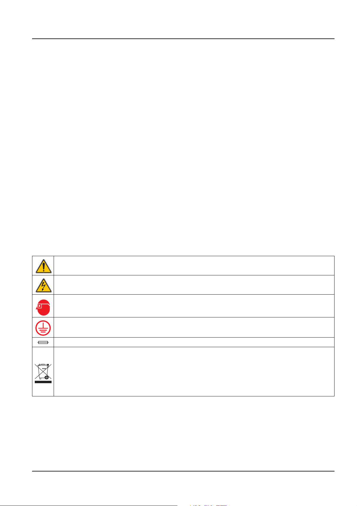
2.1.2 Precautionary Labels
Read all labels and tags attached to the instrument. Personal injury or damage to the
instrument could occur if not observed
This symbol, if noted on the instrument, references the instruction manual for operation
and/or safety information.
This symbol, when noted on a product enclosure or barrier, indicates that a risk of electrical shock and/or
electrocution exists.
This symbol, if noted on the product, indicates the need for protective eye wear.
This symbol, when noted on the product, identifies the location of the connection for Protective Earth
(ground).
This symbol, when noted on the product, identifies the location of a fuse or current limiting device.
Electrical equipment marked with this symbol may not be disposed of in European public disposal
systems after 12 August of 2005. In conformity with European local and national regulations (EU
Directive 2002/96/EC), European electrical equipment users must now return old or end-of life equipment
to the Producer for disposal at no charge to the user.
Note: For all electrical products (marked or unmarked) which are supplied or produced by Hach-Lange, please
contact the local Hach-Lange sales office for instructions for proper disposal.
7
Page 12
General Information
2.2 General Sensor Information
The Contacting Conductivity Sensor allows aqueous samples to be easily and accurately
analyzed for conductivity. Sensor models are available for applications with temperatures
up to 200 °C (392 °F). Refer to Figure 1: and Figure 6: for sensor options.
Optional equipment, such as mounting hardware for the probe, is supplied with
instructions for all user installation tasks. Several mounting options are available, allowing
the probe to be adapted for use in many different applications.
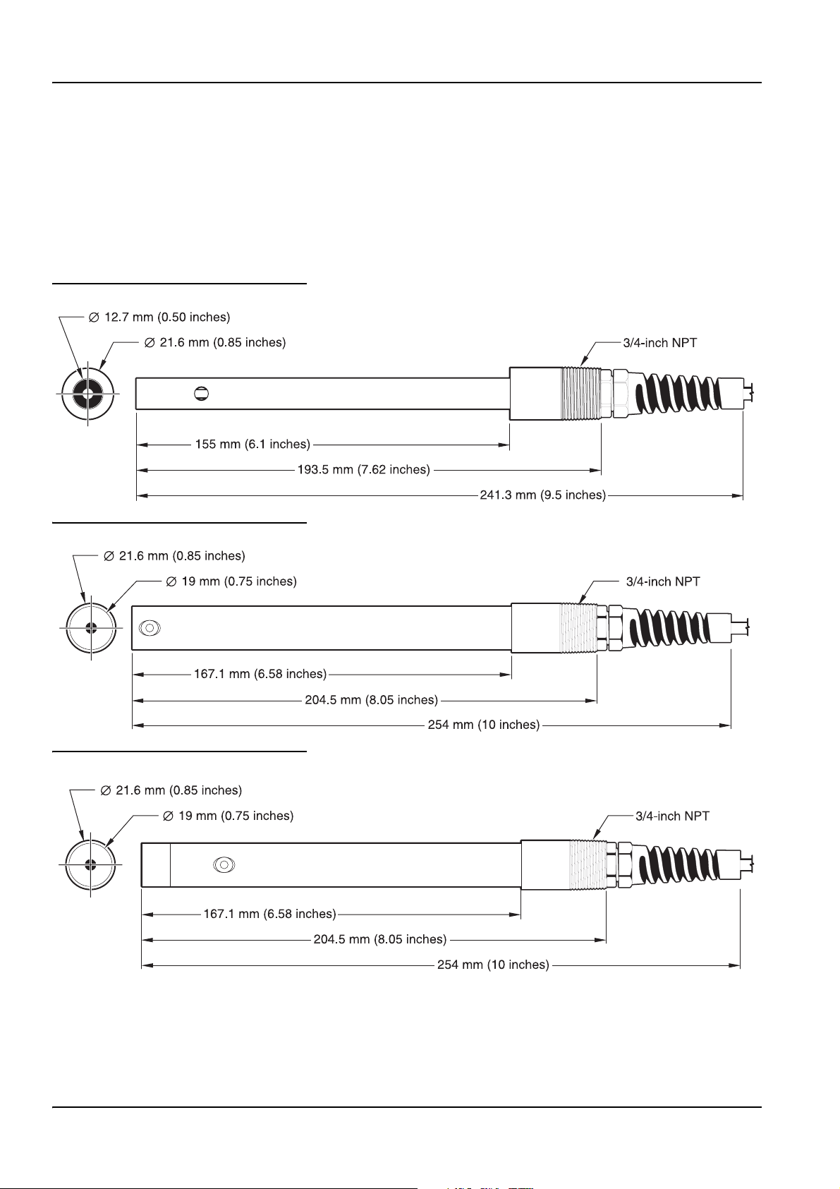
Figure 1: Compression-style Sensor, 0.5-in. Diameter
Figure 2: Compression-style Sensor, 0.75-in Diameter
Figure 3: Compression-style Sensor with Teflon® Tip
8
Page 13
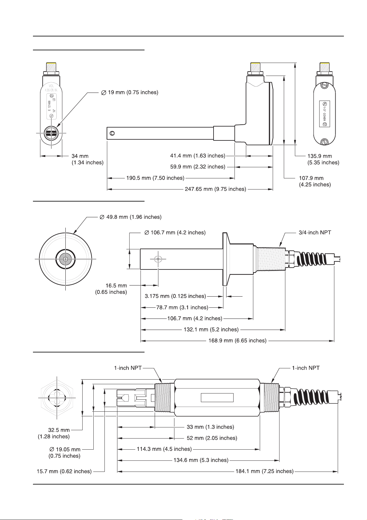
Figure 4: Compression-style Sensor (with integral junction box)
Figure 5: Sanitary (CIP)-style Sensor
General Information
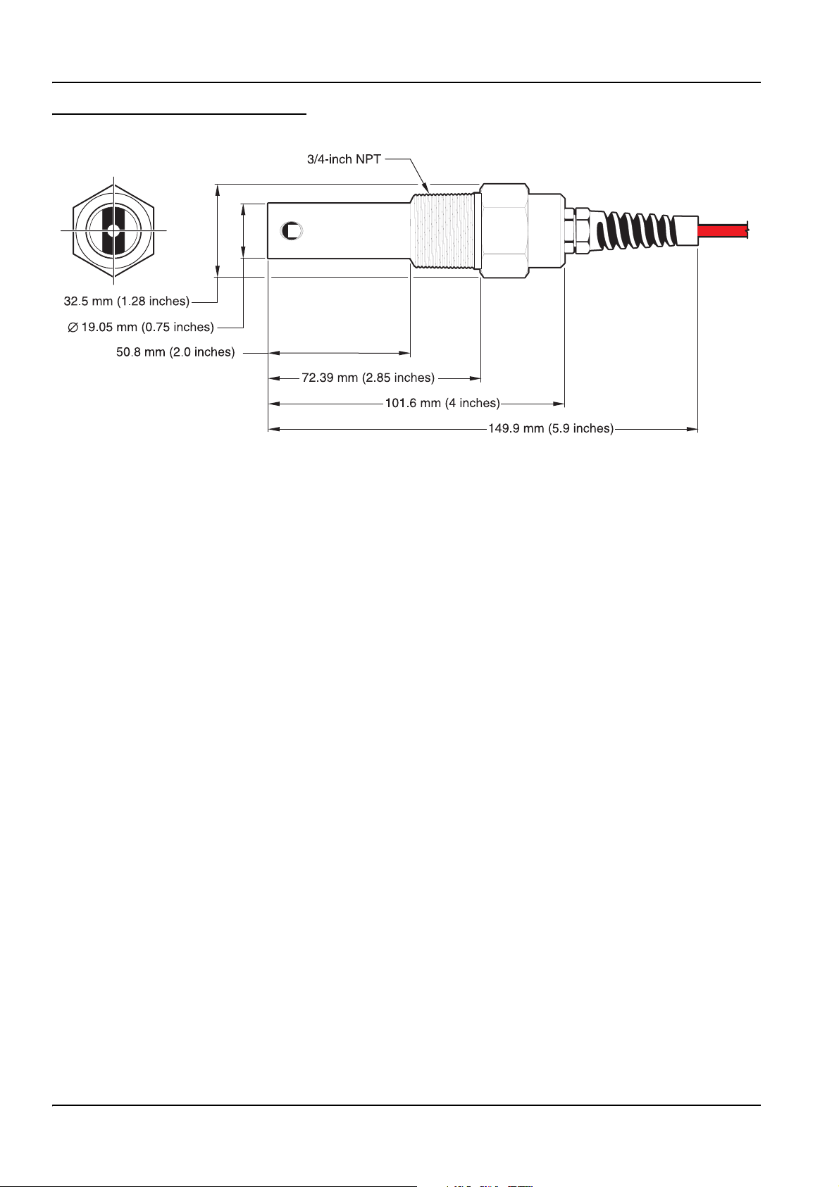
Figure 6: Non-metallic General Purpose Sensor
9
Page 14
General Information
Figure 7: Boiler/Condensate Sensor
2.3 The Digital Gateway
The Digital Gateway was developed to provide a means to use existing analog sensors
with the new digital controllers. The gateway contains all the necessary software and
hardware to interface with the controller and output a digital signal.
2.4 Theory of Operation
The Contacting Conductivity Sensors are designed to accurately measure
conductivity/resistivity/TDS/salinity from ultrapure water (0.056 µS/cm) to 200,000 µS/cm
in clear fluids. Conductivity is a measure of the ability of a solution to conduct an electric
current and resistivity is the measure of the ability of a solution to resist an electric current.
Total Dissolved Solids (TDS) is a measure that reflects the amount of solids dissolved in a
water sample and salinity is a measure of the dissolved salts in a solution.
Each sensor is available in a variety of precisely measured cell constants and different
materials to meet many measurement needs and are ideal for deionization, reverse
osmosis, electro-deionization, desalination, chemical purity, and other clear fluid
applications.
Each sensor is individually tested to determine its absolute cell constant (shown on its
label as K =X) and temperature element value (to the nearest 0.1 ohm). The cell constant
(K) and temperature factor (T) are entered during instrument configuration or calibration to
ensure the highest possible measurement accuracy.
Available cell constants include: 0.05, 0.5, 1.0, 5.0, and 10. The temperature element was
designed to provide fast response to changes in temperature and ensure high
measurement accuracy.
10
Page 15
Section 3 Installation
DANGER
Only qualified personnel should conduct the tasks described in this section of the
manual.
The system can be used with any sc controller. Refer to the controller manual for
installation instructions.
The Contacting Conductivity sensor may be ordered with an internal or external digital
gateway. If you received an external digital gateway, refer to 3.2 "Using the Digital
Gateway" on page 12 for digital gateway connecting/wiring and mounting instructions.
3.1 Connecting the Sensor to an sc Controller
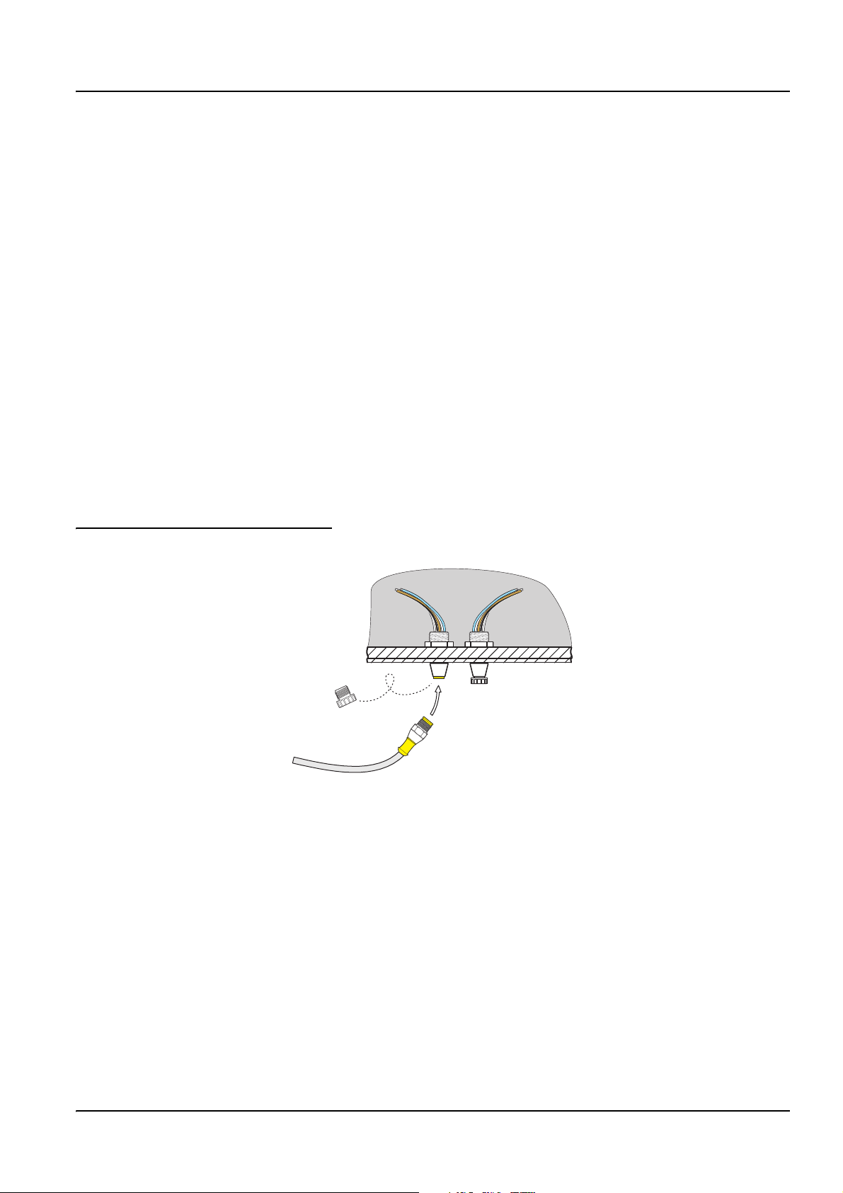
3.1.1 Attaching a sc Sensor with a Quick-connect Fitting
The sensor cable is supplied with a keyed quick-connect fitting for easy attachment to the
controller (see Figure 8: "Attaching the Sensor using the Quick-connect Fitting"). Retain
the connector cap to seal the connector opening in case the sensor must be removed.
Optional extension cables may be purchased to extend the sensor cable length. If the total
cable length exceeds 100 m (300 ft), a termination box must be installed.
Note: Use of a load termination box other than Cat. No. 5867000 may result in a hazard.
Figure 8: Attaching the Sensor using the Quick-connect Fitting
11
Page 16
Installation
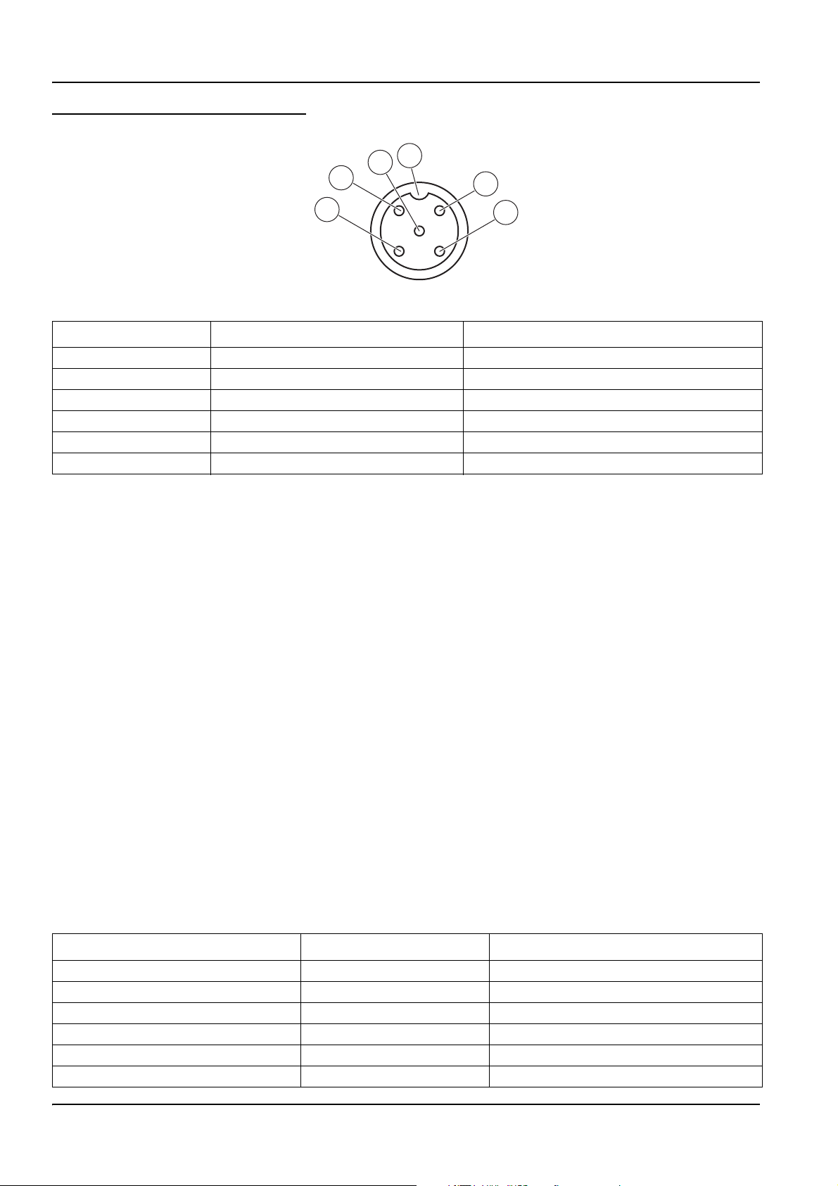
Figure 9: Quick-connect Fitting pin assignment
5
4
6
1
3
Number Designation Wire Color
1 +12 VDC Brown
2 Circuit Common Black
3 Data (+) Blue
4 Data (–) White
5 Shield Shield (grey wire in existing quick-disconnect fitting)
6Groove
3.2 Using the Digital Gateway
The digital gateway is designed to provide a digital interface to the controller. The
non-sensor end is wired to the controller as shown in "Connecting the Sensor to an sc
Controller" on page 11.
3.2.1 Wiring the sc Sensor to the Digital Gateway
2
1. Route the cable from the sensor through the strain relief in the digital gateway then
properly terminate the wire ends.
Note: Do not tighten the strain relief until the digital gateway is wired and the two halves are
threaded securely together.
2. Insert the wires as shown in Table 5: "Wiring the Digital Gateway" and Figure 10:
"Wiring and Assembling the Digital Gateway".
3. Make sure the O-ring is properly installed between the two halves of the digital
gateway and thread the two halves together. Hand tighten.
4. Tighten the strain relief to secure the sensor cable.
5. Connect the digital gateway to the controller.
Table 5: Wiring the Digital Gateway
Sensor (wire color) Sensor Signal Digital Gateway Sensor Wire connector
Clear Shield J1-1
Clear w/shrink wrap Shield J1-1
Red Drive J1-2
White Temp – J1-3
Blue Temp + J1-4
Black Sense J1-5
12
Page 17

Figure 10: Wiring and Assembling the Digital Gateway
Installation
1. Digital gateway front 7. Nut, strain relief
2. O-ring 8. From sensor
3. Sensor wire connector 9. Insert wires into connector according to Table 5:. Use the included 2 mm
screwdriver (Cat. No. 6134300) to secure connections.
4. Digital gateway back 10. Screw back of digital gateway onto front
5. Cable bushing 11. Push cable bushing and anti-rotation washer into back.
6. Anti-rotation washer 12. Fasten cord grip securely. Assembly is complete.
13
Page 18

Installation
3.2.2 Mounting the Digital Gateway
The digital gateway is supplied with a mounting clip for mounting to a wall or other flat
surface. Use an appropriate fastener to secure it to the wall. After the sensor is wired to
the digital gateway and the two halves are threaded together, place the mounting clip over
the center of the digital gateway and squeeze the clip together to secure. See Figure 12:
"Mounting the Digital Gateway".
Figure 11: Digital Gateway Dimensions
34.29 mm
(1.35 inches)
184.15 mm (7.25 inches)
Figure 12: Mounting the Digital Gateway
1. Mounting clip 3. Hex nut, ¼-28
2. Screw, pan head, ¼-28 x 1.25-in.es 4. Mount clip, insert digital gateway, squeeze clip closed.
14
Page 19

3.3 Installing the Sensor in the Sample Stream
Two compression-style installation schemes are available. For sensors with a 0.05 cell
constant, use ½-in or ¾-in male NPT compression fittings made of Kynar (PVDF) or
316 stainless steel. For sensors with any other cell constant, use a ¾-in. male NPT
compression fitting made of Kynar or 316 stainless steel. In all cases, the fitting enables
the sensor to be insertion mounted, up to 102 mm (4 in.) deep, into a pipe tee or vessel.
Reversing the fitting enables the sensor to be fastened onto the end of a pipe for
immersion mounting.
A longer version of the sensor can be installed into a 316 stainless steel ball valve
assembly to insert/retract the sensor without stopping the process flow. Maximum
insertion depth is 178 mm (7 in.).
Examples of common sensor installations are shown in Figure 13: "Sensor Installation
Examples" and dimension drawings are shown in Figure 1: "Compression-style Sensor,
0.5-in. Diameter" on page 8 through Figure 7: "Boiler/Condensate Sensor" on page 10.
Refer to the instructions supplied with the mounting hardware for installation specifics.
Installation
15
Page 20

Installation
Figure 13: Sensor Installation Examples
1. Insertion mounting 5. End of pipe immersion
2. Insertion mounting 6. Non-metallic sensor, end of pipe immersion
3. Non-metallic sensor, insertion mounting 7. Sanitary (CIP) flange mounting
4. Boiler wall insertion mounting 8. Ball valve insertion for compression-style sensor with extended sensor
body
16
Page 21

Section 4 Operation
4.1 Using an sc Controller
Before using the sensor in combination with an sc controller make yourself familiar with
the operating mode of the controller. Refer to the controller user manual and learn how to
use and navigate the menu functions.
4.2 Sensor Setup
When a sensor is initially installed, the serial number of the sensor will be displayed as the
sensor name. To change the sensor name refer to the following instructions:
1. Select the Main Menu.
2. From the Main Menu, select SENSOR SETUP and confirm.
3. Select the appropriate sensor if more than one sensor is attached and confirm.
4. Select CONFIGURE and confirm.
5. Select EDIT NAME and edit the name. Confirm or cancel to return to the Sensor
Setup menu.
4.3 Sensor Data Logging
The sc controller provides one data log and one event log for each sensor. The data log
stores the measurement data at selected intervals. The event log stores a variety of events
that occur on the devices such as configuration changes, alarms, warning conditions, etc.
The data log and the event log can be read out in a CSV format. For downloading the logs
please refer to the controller user manual.
4.4 SENSOR STATUS Menu
SELECT SENSOR
ERROR LIST See 6.1 "Error Codes" on page 25.
WARNING LIST See 6.2 "Warnings" on page 25.
4.5 SENSOR SETUP Menu
SELECT SENSOR (if more than one sensor is attached)
CALIBRATE
ZERO
1 POINT SAMPLE
TEMP ADJUST
DEFAULT SETUP Return the instrument to the default calibration settings.
Perform a zero cal to remove sensor offset (4.6.1 "Zero Cal"
on page 19).
Perform a single point calibration (4.6.2 "One Point Sample
Calibration" on page 20).
Displays the measured temperature and allows the user to
edit the displayed temperature by ± 5 °C.
17
Page 22

Operation
4.5 SENSOR SETUP Menu
SELECT SENSOR (if more than one sensor is attached)
CONFIGURE
EDIT_NAME
SELECT MEASURE
MEAS UNITS
TEMP UNITS Select Celsius or Fahrenheit. Default: Celsius
DISPLAY FORMAT
FILTER
LOG SETUP
CONFIG TDS
This menu appears only if the selected parameter
is TDS.
CELL CONSTANT
T–COMPENSATION
TEMP ELEMENT
AC FREQUENCY
DEFAULT SETUP Reset the configure settings to the factory defaults.
Enter a 10-digit name in any combination of symbols and
alpha or numeric characters.
Choose from Conductivity, Resistivity, TDS, or Salinity.
Default: Conductivity
Choose from the displayed units (dependent on the
parameter selected in the Set Parameter menu)
Choose from the presented options to set the display
resolution.
Average the measurement over time by entering a number
between 0–60. Default is 0.
Choose from Sensor Interval or Temp Interval. If the interval
is enabled, choose from the displayed options to specify the
frequency to log the sensor or temperature reading. Default is
Disabled.
This menu appears only if the selected parameter is TDS.
Set TDS factor. Default is 0.49 ppm/µS.
Choose Select Cell K to choose a nominal cell constant value
from the displayed options that is close to the “K” value
provided with the sensor. Then choose Set Cell K to enter the
specific “K” value supplied with the sensor. Entering the “K”
value eliminates the need for calibration until the sensor is
replaced and sets the analyzer measurement range to
correspond to the specified cell constant.
The factory default for temperature compensation is linear
with a 2.00% per °C slope and a 25 °C reference
temperature. The default settings are appropriate for most
aqueous solutions. To enter different slope and reference
temperature values for an uncommon solution, access the
menu options described below.
LINEAR: Recommended for most applications. Confirm to
change the slope or reference temperature.
AMMONIA: Not available for TDS. Contact Technical Support
for application specific information and assistance.
NATURAL WATER: Unavailable for TDS. Contact Technical
Support for application specific information and assistance.
USER TABLE: Use to configure a temperature compensation
table by entering up to 10 x-axis parameters and 10 y-axis
parameters. Contact Technical Consulting Services for
additional information and assistance.
Select the temperature element type (100PT, 1000PT
(default), or manual) then choose Select Factor to enter the
specific “T” Factor supplied with the sensor.
Choose 50 or 60 Hz depending on the power line frequency
for optimal noise rejection. Default is 60 Hz.
18
Page 23

4.5 SENSOR SETUP Menu
SELECT SENSOR (if more than one sensor is attached)
DIAG/TEST
PROBE INFO
SIGNALS
CAL DATA
4.6 Calibration
Each contacting conductivity sensor has a unique zero point and offset. Always zero the
sensor when calibrating it for the first time. Zeroing provides the best possible
measurement accuracy and eliminates discrepancies between sensor measurements on
two different channels. Zeroing should always be followed by a calibration.
Operation
Display the probe device driver version number, software
version number, or probe 12-digit serial number using this
menu.
Display the conductivity A/D counts or the temperature output
in Ohms
Display the
CELL K: 1.00000 (current cell constant),
TEMP ADJ: current temperature offset correction,
ZERO 1: Zero counts for gain 1,
ZERO 2: Zero counts for gain 2,
ZERO 3: Zero counts for gain 3
4.6.1 Zero Cal
Zero the sensor if it is being calibrated for the first time. Make sure the sensor is dry before
zeroing.
1. Select the Main Menu.
2. From the Main Menu, select SENSOR SETUP and confirm.
3. Select the appropriate sensor if more than one sensor is attached and confirm.
4. Select CALIBRATE and confirm.
5. Select ZERO and confirm.
6. Select the available Output Mode (Active, Hold, or Transfer) from the list box and
confirm.
7. Move the sensor to air and confirm to continue.
8. The zero calibration procedure will begin and “WAIT TO STABILIZE” will be displayed.
9. Confirm, when the current value and temperature will be displayed.
10. Return the sensor to the process.
19
Page 24

Operation
4.6.2 One Point Sample Calibration
The wet calibration requires that the sensor be immersed into a properly prepared
conductivity reference solution or if installed in the process sample, the process value
must be determined by laboratory analysis or comparison reading.
Remove the probe from the process and clean it. Obtain a sample solution with a known
value and proceed as follows:
1. Select the Main Menu.
2. From the Main Menu, select SENSOR SETUP and confirm.
3. Select the appropriate sensor if more than one sensor is attached and confirm.
4. Select CALIBRATE and confirm.
5. Select ZERO and confirm.
6. Select 1 POINT SAMPLE and confirm.
7. Select the available Output Mode (Active, Hold, or Transfer) from the list box and
confirm.
8. Move the sensor to the sample and confirm to continue.
9. Confirm when stable.
10. Edit the value and temperature using the keypad and confirm.
11. Return the sensor to the process.
4.6.3 Concurrent Calibration of Two Sensors
1. Begin a calibration on the first sensor and continue until “WAIT TO STABILIZE”
is displayed.
2. Select Leave and confirm.
The display will return to the Main Measurement screen and the reading for both sensors
will be flashing.
3. Begin the calibration for the second sensor and continue until “WAIT TO STABILIZE”
is displayed.
4. Select LEAVE.
The display will return to the Main Measurement screen and the reading for both sensors
will be flashing. The calibration for both sensors are now running in the background.
20
5. To return to the calibration of either sensor, select the Main Menu
6. Select SENSOR SETUP and confirm.
7. Select the appropriate sensor and confirm.
8. The calibration in progress will be displayed. Continue with the calibration.
Page 25

4.6.3.1 Preparing Conductivity Reference Solutions
Use Table 6: "Conductivity Reference Solutions" on page 21 to prepare a conductivity
reference solution with a value between 200 and 100,000 µS/cm. The value prepared
should be near the typical measured process value for best accuracy. Add the listed grams
of pure, dried NaCl to one liter of high-purity, deionized, CO
the stated conductivity.
Table 6: Conductivity Reference Solutions
Operation
-free water at 25 °C to obtain
2
Desired Solution Value
µS/cm mS/cm ppm (NaCl)
100 0.10 50 0.05
200 0.20 100 0.10
500 0.50 250 0.25
1000 1.00 500 0.50
2000 2.00 1010 1.01
3000 3.00 1530 1.53
4000 4.00 2060 2.06
5000 5.00 2610 2.61
8000 8.00 4340 4.34
10000 10.00 5560 5.56
20000 20.00 11590 11.59
1
When using the ppm measuring scale for compounds other than NaCl, refer to the appropriate chemistry handbook for reference
solution for formulation.
1
Grams NaCl to be added
4.7 Adjusting the Temperature
View or change the temperature using the steps below.
1. Select the Main Menu.
2. From the Main Menu, select SENSOR SETUP and confirm.
3. Select the appropriate sensor if more than one sensor is attached and confirm.
4. Select DIAG/TEST and confirm.
5. Select TEMP ADJUST and confirm.
The temperature will be displayed.
6. Edit the temperature and confirm.
21
Page 26

Operation
22
Page 27

Section 5 Maintenance
DANGER
Only qualified personnel should conduct the tasks described in this section of the
manual.
5.1 Maintenance Schedule
Maintenance Task 90 days Annually
1
Clean the sensor
Calibrate Sensor (if required by regulatory agency) Per the schedule mandated by your regulatory agency.
1
Cleaning frequency is application dependent. More or less frequent cleaning will be appropriate in some applications.
5.2 Cleaning the Sensor
CAUTION
Before cleaning with acid, determine if any hazardous reaction products could
form. (For example, a sensor used in a cyanide bath should not be put directly into
a strong acid for cleaning because poisonous cyanide gas could be produced.)
Acids are hazardous. Wear appropriate eye protection and clothing in accordance
with Material Safety Data Sheet recommendations.
x
Keep the sensor clean to maintain measurement accuracy. The time between cleaning
(days, weeks, etc.) is affected by the characteristics of the process solution and can only
be determined by operating experience.
1. Clean the exterior of the sensor with a stream of water. If debris remains, wipe with a
soft, wet cloth.
2. Remove most contaminate buildup by carefully wiping the inner electrode rod, and the
concentric outer electrode tube (inner and outer surfaces) with a soft clean cloth. Then
rinse the sensor with clean, warm water.
3. Prepare a mild soap solution using warm water and dishwashing detergent or similar.
4. Soak the sensor for 2 to 3 minutes in the soap solution.
5. Use a soft brush, cotton swab, or pipe cleaner to scrub the entire measuring end of the
sensor, thoroughly cleaning the electrode surfaces.
6. If detergent solution cleaning cannot remove surface deposits, use muriatic acid (or
another dilute acid) to dissolve the deposits. Soak the sensor in dilute acid no more
than 5 minutes.
Note: The acid should be as dilute as possible, but yet strong enough to clean. Experience will help
determine which acid to use and how dilute it can be. Some stubborn coatings may require a
different cleaning agent. For assistance in these difficult cases, contact Technical Consulting
Services.
7. Rinse the sensor with clean, warm water and then place the sensor back into the mild
soap solution for 2 to 3 minutes to neutralize any remaining acid.
8. Rinse the sensor in clean, warm water.
23
Page 28

Maintenance
9. Calibrate the analyzer using the procedure in the analyzer instruction manual. If
calibration cannot be attained, check the sensor using the procedure in the
troubleshooting section.
24
Page 29

Section 6 Troubleshooting
6.1 Error Codes
When a sensor is experiencing an error condition, the sensor reading on
the measurement screen will flash and all relays and analog outputs associated with this
sensor will be held. The following conditions will cause the sensor reading to flash:
• Sensor calibration
• Relay timer washing cycle
• Loss of communication
Select the SENSOR STATUS menu and confirm. Select ERRORS and confirm to
determine the cause of the error. Errors are defined in Table 7: "Error Codes".
Table 7: Error Codes
Displayed Error Definition Resolution
ADC FAIL ADC reading bad Contact Customer Service
SENSOR FAIL Sensor ADC reading bad Contact Customer Service
FLASH FAIL Failed operation on Flash Memory Contact Customer Service
6.2 Warnings
A Sensor Warning will leave all menus, relays, and outputs functioning normally, but will
cause a warning icon to flash on the right side of the display. Select WARNINGS and
confirm to determine the cause of the warning.
A warning may be used to trigger a relay and users can set warning levels to define the
severity of the warning. Warnings are defined in Table 8: "Warning Codes".
Table 8: Warning Codes
Displayed Warning Definition Resolution
Temperature out of Range: Increase process temperature
or discontinue use until the process temperature is above
–20 °C (–4 °F).
Bad Temperature Sensor: Check temperature of the
sample stream with an independent temperature
measuring device. If the temperature is within range,
contact the Technical Consulting Services Department.
Temperature out of Range: Decrease process temperature
or discontinue use until the process temperature is below
200 °C (392 °F).
Bad Temperature Sensor: Check temperature of the
sample stream with an independent temperature
measuring device. If the temperature is within range,
contact the Technical Consulting Services Department.
TEMP < –20 °C
TEMP > 200 °C
The sensed temperature is below –20 °C
(–4 °F).
The sensed temperature is above 200 °C
(392 °F).
25
Page 30

Troubleshooting
6.3 General Troubleshooting
Problem Resolution
Reading is unstable Clean and calibrate sensor
6.4 Checking Sensor Operation
6.4.1 Sensors without the Integral Junction Box
Use the following troubleshooting steps for sensors without the integrated integral junction
box (Model: D3422, D3433, D3444, and D3455).
1. Disconnect the sensor from the analyzer or junction box.
2. Clean the sensor using the procedure in 5.2 "Cleaning the Sensor" on page 23.
3. Using an ohmmeter, check all of the measurement point resistance readings shown in
Table 9: " Sensor Operations (Resistance) Checks for Models 3422 and 3455",
Table 10: " Sensor Operations (Resistance) Checks for Models 3433", and
Table 11: " Sensor Operations (Resistance) Checks for Models 3422 and 3455".
Make sure that the ohmmeter is set to its highest range for all infinite (open circuit)
resistance readings.
4. If you cannot get the required readings for one or more of the resistance check or if
the sensor still does not operate when the resistance checks are okay, contact
Technical Support for more troubleshooting options.
Table 9: Sensor Operations (Resistance) Checks for Models 3422 and 3455
Measurement Points Correct Resistance Readings
Between blue and white wires 1089–1106 ohms at 23–27 °C
Between red wire and sensor body Less than 5 ohms
Between black wire and inner electrode Less than 5 ohms
Between black and red wires Infinite (open circuit)
Between black and white wires Infinite (open circuit)
Between red and white wires Infinite (open circuit)
Between red and inner shield wires Infinite (open circuit)
Between black and inner shield wires Infinite (open circuit)
Between white and inner shield wires Infinite (open circuit)
Between outer and inner shield wires Infinite (open circuit)
26
Page 31

Troubleshooting
Table 10: Sensor Operations (Resistance) Checks for Models 3433
Measurement Points Correct Resistance Readings
Between blue and white wires 1089–1106 ohms at 23–27 °C
Between black and red wires Infinite (open circuit)
Between black and white wires Infinite (open circuit)
Between red and white wires Infinite (open circuit)
Between red and inner shield wires Infinite (open circuit)
Between black and inner shield wires Infinite (open circuit)
Between white and inner shield wires Infinite (open circuit)
Between outer and inner shield wires Infinite (open circuit)
Table 11: Sensor Operations (Resistance) Checks for Models 3422 and 3455
Measurement Points Correct Resistance Readings
Between blue and white wires 1089–1106 ohms at 23–27 °C
Between red wire and sensor body Less than 5 ohms
Between black wire and inner electrode Less than 5 ohms
Between black and red wires Infinite (open circuit)
Between black and white wires Infinite (open circuit)
Between red and white wires Infinite (open circuit)
Between red and outer shield wires Infinite (open circuit)
Between black and outer shield wires Infinite (open circuit)
Between white and outer shield wires Infinite (open circuit)
Between outer and outer shield wires Infinite (open circuit)
6.4.2 Analog or External Digital Gateway Sensors
1. Disconnect the sensor from the analyzer or junction box.
2. Clean the sensor using the procedure in "Cleaning the Sensor" on page 23.
3. Obtain a known standard (NIST-traceable is preferred for many applications) and take
a measurement.
4. Reconnect the sensor to the controller or junction box.
5. If the resulting measurement is out of specification (different from the value stated on
the label ± the stated standard error), contact Technical Consulting Services. See
"Adresses" on page 33 for contact information.
27
Page 32

Troubleshooting
6.4.3 Sensor Linearity Check
1. Obtain two standards, one close to the maximum for the range of interest (high
standard) and another with a value half way between the high standard and 0
(mid-range standard).
2. Prepare 50 mL high and mid-range standards in 100 mL beakers and add 50 mL of
deionized water to another 100 mL beaker.
3. Insert the sensor into the beaker containing deionized water. Record the stable
reading.
4. Remove the sensor from the deionized water and shake it gently to remove excess
water.
5. Place the sensor into the high standard and record the stable reading.
6. Remove the sensor from the high standard, rinse with deionized water and shake
gently to remove excess water.
7. Place the sensor in the mid-range standard and record the stable reading.
The mid-range standard reading should fall half way between the reading obtained for the
deionized water and the high standard. If it does not, the sensor may be defective. Call
Customer Service for assistance; see "Adresses" on page 33 for contact information.
28
Page 33

Section 7 Replacement Parts
7.1 Replacement Items and Accessories
Item QTY Catalog Number
Cable, sensor extension, 0,35 m each LZX847
Cable, sensor extension, 5 m each LZX848
Cable, sensor extension, 10 m each LZX849
Cable, sensor extension, 15 m each LZX850
Cable, sensor extension, 20 m each LZX851
Cable, sensor extension, 30 m each LZX852
Cable, sensor extension, 50 m each LZX853
Load termination box, required for total cable lengths greater than 100m (328ft) each 58670-00
Conductivity Reference Solution, 100–1000 µs/cm 1L 25M3A2000-119
Conductivity Reference Solution, 100–1000 µs/cm 1L 25M3A2050-119
Conductivity Reference Solution, 2000–100000 µs/cm 1L 25M3A2100-119
Conductivity Reference Solution, 200000–300000 µs/cm 1L 25M3A2200-119
Connector Safety Lock each 6139900
Digital termination box each 5867000
user manual, sc100 Controller, English each DOC023.52.00032
user manual, sc1000 Controller, English each DOC023.52.03260
user manual, Conductivity System, English each DOC023.52.03249
Mount Hardware, Insertion (Ball Valve), 3422 series, SS, 0.05 cell constant each MH113M2C
Mount Hardware, Insertion (Ball Valve), 3422 series, SS for all other cell constants each MH114M2C
Mounting hardware kit, pipe each 5794400
Mounting hardware kit, ball float each 5794300
Plug, sealing, conduit opening each 5868700
Strain relief, Heyco each 16664
29
Page 34

Replacement Parts
30
Page 35

Section 8 Warranty, liability and complaints
HACH LANGE GmbH warrants that the product supplied is free of material and
manufacturing defects and undertakes the obligation to repair or replace any defective
parts at zero cost.
The warranty period for instruments is 24 months. If a service contract is taken out within 6
months of purchase, the warranty period is extended to 60 months.
With the exclusion of the further claims, the supplier is liable for defects including the lack
of assured properties as follows: all those parts that can be demonstrated to have become
unusable or that can only be used with significant limitations due to a situation present
prior to the transfer of risk, in particular due to incorrect design, poor materials or
inadequate finish will be improved or replaced, at the supplier's discretion. The
identification of such defects must be notified to the supplier in writing without delay,
however at the latest 7 days after the identification of the fault. If the customer fails to notify
the supplier, the product is considered approved despite the defect. Further liability for any
direct or indirect damages is not accepted.
If instrument-specific maintenance and servicing work defined by the supplier is to be
performed within the warranty period by the customer (maintenance) or by the supplier
(servicing) and these requirements are not met, claims for damages due to the failure to
comply with the requirements are rendered void.
Any further claims, in particular claims for consequential damages cannot be made.
Consumables and damage caused by improper handling, poor installation or incorrect use
are excluded from this clause.
HACH LANGE GmbH process instruments are of proven reliability in many applications
and are therefore often used in automatic control loops to provide the most economical
possible operation of the related process.
To avoid or limit consequential damage, it is therefore recommended to design the control
loop such that a malfunction in an instrument results in an automatic change over to the
backup control system; this is the safest operating state for the environment and the
process.
31
Page 36

Warranty, liability and complaints
8.1 Compliance Information
Hach Co. certifies this instrument was tested thoroughly, inspected and found to meet its
published specifications when it was shipped from the factory.
The Model sc100 Controller/sc1000 Controller with Contacting Conductivity Probe
has been tested and is certified as indicated to the following instrumentation standards:
Product Safety
UL 61010A-1 (ETL Listing # 65454)
CSA C22.2 No. 1010.1 (ETLc Certification # 65454)
Certified by Hach Co. to EN 61010-1 Amds. 1 & 2 (IEC1010-1) per 73/23/EEC,
supporting test records by Intertek Testing Services.
Immunity
This equipment was tested for industrial level EMC per:
EN 61326 (EMC Requirements for Electrical Equipment for Measurement, Control
and Laboratory Use)
Company, certified compliance by Hach Company.
per 89/336/EEC EMC: Supporting test records by Hach
Emissions
Standards include:
IEC 1000-4-2:1995 (EN 61000-4-2:1995) Electrostatic Discharge Immunity (Criteria
B)
IEC 1000-4-3:1995 (EN 61000-4-3:1996) Radiated RF Electromagnetic Field
Immunity (Criteria A)
IEC 1000-4-4:1995 (EN 61000-4-4:1995) Electrical Fast Transients/Burst (Criteria B)
IEC 1000-4-5:1995 (EN 61000-4-5:1995) Surge (Criteria B)
IEC 1000-4-6:1996 (EN 61000-4-6:1996) Conducted Disturbances Induced by RF
Fields (Criteria A)
IEC 1000-4-11:1994 (EN 61000-4-11:1994) Voltage Dip/Short Interruptions (Criteria
B)
Additional Immunity Standard/s include:
ENV 50204:1996 Radiated Electromagnetic Field from Digital Telephones (Criteria A)
This equipment was tested for Radio Frequency Emissions as follows:
Per 89/336/EEC EMC: EN 61326:1998 (Electrical Equipment for measurement,
control and laboratory use—EMC requirements) Class “A” emission limits. Supporting
test records by Hewlett Packard, Fort Collins, Colorado Hardware Test Center (A2LA
# 0905-01) and certified compliance by Hach Company.
32
Standards include:
EN 61000-3-2 Harmonic Disturbances Caused by Electrical Equipment
EN 61000-3-3 Voltage Fluctuation (Flicker) Disturbances Caused by Electrical
Equipment
Additional Emissions Standard/s include:
EN 55011 (CISPR 11), Class “A” emission limits
Page 37

Section 9 Adresses
HACH LANGE GmbH
Willstätterstraße 11
D-40549 Düsseldorf
Tel. +49 (0) 211- 52 88 - 0
Fax +49 (0) 211- 52 88 - 143
info@hach-lange.de
www.hach-lange.de
DR. BRUNO LANGE
GES. MBH
Industriestraße 12
A-3200 Obergrafendorf
Tel. +43 (0) 2747 - 74 12
Fax +43 (0) 2747 - 42 18
info@hach-lange.at
www.hach-lange.de
DR. LANGE NEDERLAND B.V.
Laan van Westroijen 2a
NL-4003 AZ Tiel
Tel. +31(0)3 44 63 11 30
Fax +31(0)3 44 63 11 50
info@hach-lange.nl
www.hach-lange.nl
HACH LANGE LTD
Pacific Way
Salford
Manchester, M50 1DL
Tel. +44 (0)161 8 72 14 87
Fax +44 (0)161 8 48 73 24
info@hach-lange.co.uk
www.hach-lange.co.uk
DR. BRUNO LANGE AG
Juchstrasse 1
CH-8604 Hegnau
Tel. +41 (0)44- 9 45 66 10
Fax +41 (0)44- 9 45 66 76
info@hach-lange.ch
www.hach-lange.ch
HACH LANGE AB
Vinthundsvägen159A
S-128 62 Sköndal
Tel. +46 (0)8 7 98 05 00
Fax +46 (0)8 7 98 05 30
info@hach-lange.se
www.hach-lange.se
HACH LANGE
HACH SAS
33, Rue du Ballon
F-93165 Noisy Le Grand
Tél. +33 (0)1 48 15 8080
Fax +33 (0)1 48 15 80 00
info@hach-lange.fr
www.hach-lange.fr
HACH LANGE SA
Motstraat 54
B-2800 Mechelen
Tél. +32 (0)15 42 35 00
Fax +32 (0)15 41 61 20
info@hach-lange.be
www.hach-lange.be
HACH LANGE A/S
Åkandevej 21
DK-2700 Brønshøj
Tel. +45 36 77 29 11
Fax +45 36 77 49 11
info@hach-lange.dk
www.hach-lange.dk
HACH LANGE S.L.U.
C/Araba 45, Apdo. 220
E-20800 Zarautz/Guipúzcoa
Tel. +34 9 43 89 43 79
Fax +34 9 43 13 02 41
info@hach-lange.es
www.hach-lange.es
HACH LANGE S.R.O.
Lešanská 2a/1176
CZ-141 00 Praha 4
Tel. +420 272 12 45 45
Fax +420 272 12 45 46
info@hach-lange.cz
www.hach-lange.cz
HACH LANGE SP.ZO.O.
ul. Opolska 143 a
PL-52-013 Wroclaw
Tel. +48 71 3 42 10-81
Fax +48 71 3 42 10-79
info@hach-lange.pl
www.hach-lange.pl
HACH LANGE S.R.O.
Sabinovská 10
SK-821 02 Bratislava
Tel. +421 2 4820 9091
Fax +421 2 4820 9093
info@hach-lange.sk
www.hach-lange.com
HACH LANGE S.R.L.
Via Riccione, 14
I-20156 Milano
Tel. +39 02 39 23 14-1
Fax +39 02 39 23 14-39
info@hach-lange.it
www.hach-lange.it
HACH LANGE LDA
Rua dos Malhões,
Edif. D. Pedro I
P-2770-071 Paço D'Arcos
Tel. +351 210 00 1750
Fax +351 210 00 8140
info@hach-lange.pt
www.hach-lange.pt
33
Page 38

34
Page 39

Appendix A Additional information for series 34xx sensors
A.1 Additional information for series 3410 ... 3412 sensors
This additional information is only applicable for sensors of types
• 3410,
• 3411 and
• 3412.
For all other information necessary for the operation of the sensors, please see the
operating instructions for the analysis systems installed.
A.1.1 Technical data for the 43410 ... 3412 sensors
Series 3410/3411 3412
Maximum sample temperature 125 °C at 10 bar
Maximum sample pressure 10 bar at 125 °C
Cell constant K *
0.01 cm
0.1 cm
1 cm
* The cell constant has a precision of ± 2 %.
–1
–1
–1
0 µS/cm ... 20 µS/cm
0 µS/cm ... 200 µS/cm
0 µS/cm ... 2000 µS/cm
Materials
Top part of housing
Inner electrode
Outer electrode
Isolator
Connector
Connection thread External thread 3/4” NPT
Black polyester
SST316L, stainless
SST316L, stainless
PES
Glass-fibre reinforced
polyester / IP 65
A.1.2 Installation of the sensors
For the necessary information please see the operating instructions for the gateway.
A.1.3 Installation of the sensor in the flow of sample
For the necessary information please see the operating instructions for the gateway.
Black polyester
Graphite
Graphite
PES
Glass-fibre reinforced
polyester / IP 65
35
Page 40

Additional information for series 34xx sensors
Figure 14: Dimensions of the 8310 ... 8312 sensors
3/4”NPT
8310
K=0,01 cm
Ø 16 (0.63)
–1
Ø 35 (1.378)
8311
K=0,1 cm
Ø 16 (0.63)
–1
8312
K=1 cm
–1
Ø 26 (1.024)
Ø 20 (0.787)
36
Page 41

Additional information for series 34xx sensors
A.2 Additional information for series 3415 ... 3417 sensors
This additional information is only applicable for sensors of types
• 3415,
• 3416 and
• 3417.
For all other information necessary for the operation of the sensors, please see the
operating instructions for the analysis systems installed.
A.2.1 Technical data for the 3415 ... 3417 sensors
Series 3415/3416 3417
Maximum sample temperature 150 °C (at 25 bar)
Maximum sample pressure 25 bar (at 150 °C)
Cell constant K *
0.01 cm
0.1 cm
1 cm
* The cell constant has a precision of ± 2 %.
Materials
–1
–1
–1
0 µS/cm ... 20 µS/cm
0 µS/cm ... 200 µS/cm
0 µS/cm ... 2000 µS/cm
Body (top part)
Inner electrode *
Outer electrode *
Isolator *
O-rings *
Connector
* In contact with the liquid medium
VITON is a registered trademark of DUPONT DE NEMOURS
Connection thread External thread 3/4” NPT
Stainless steel 316 L
Stainless steel 316 L
Stainless steel 316 L
PES
VITON
Glass-fibre reinforced
polyester / IP 65
A.2.2 Installation of the sensors
For the necessary information please see the operating instructions for the gateway.
A.2.3 Installation of the sensor in the flow of sample
For the necessary information please see the operating instructions for the gateway.
Stainless steel 316 L
Graphite
Graphite
PES
VITON
Glass-fibre reinforced
polyester / IP 65
37
Page 42

Additional information for series 34xx sensors
Figure 15: Dimensions of the 8315 ... 8317
3/4” NPT
8315
K = 0,01 cm
Ø 30 (1.181)
–1
8316
K = 0,1 cm
–1
8317
K=1cm
–1
Ø 26 (1.024)
Ø 21 (0.827)
Ø 21 (0.827)
Ø 21 (0.827)
38
Page 43

Additional information for series 34xx sensors
A.3 Additional information for series 3494 sensors
This additional information is only applicable for sensors of type 3494.
For all other information necessary for the operation of the sensors, please see the
operating instructions for the analysis systems installed.
A.3.1 Technical data for the 3494 sensors
Series 3494
Maximum sample temperature 150 °C (at 10 bar)
Maximum sample pressure 25 bar (at 100 °C)
Cell constant K
Temperature sensor
Materials
Body (top part)
Inner electrode
Outer electrode
Isolator
Sealing ring
Connector
* In contact with the liquid medium
Stainless steel 316 L, (Ra < 0.4 µm)
Stainless steel 316 L, (Ra < 0.4 µm)
Stainless steel 316 L, (Ra < 0.4 µm)
PEEK * (FDA approved)
EPDM *(FDA approved)
Glass-fibre reinforced polyester / IP 65
0.01 cm
0 µS/cm ...20 µS/cm, ±1 %
–1
, ± 2 %
± 0.15 °C
A.3.2 Installation of the sensors
For the necessary information please see the operating instructions for the gateway.
A.3.3 Installation of the sensor in the flow of sample
For the necessary information please see the operating instructions for the gateway.
39
Page 44

Additional information for series 34xx sensors
Figure 16: Dimensions of the 8394 sensors
1,5” Version 2” Version
Ø 30 (1.181) Ø 35 (1.378)
Ø 1.5” Ø 2”
Ø 18 (0.709)
Ø 18 (0.709)
40
Page 45

A.4 Digital gateway
Figure 17: Connection digital gateway / 83xx
Additional information for series 34xx sensors
1
PNK
PINK
1
WHT
WHITE
2
3
GRY
GREY
4
5
BRN
BROWN
5432
6
7
8
9
1
2
3
4
5
10
11
12
1. Front of housing 7. Union nut
2. O-ring 8. From the sensor
3. Sensor wire connections 9. Cable assignment as per
Table 12: "Cable assignment, digital gateway / 83xx" on page 44.
4. Rear of housing 10. Bolt together the housing for the digital gateway.
5. Cable sleeve 11. Slide back the cable sleeve and the washer.
6. Washer 12. Tighten the union nut.
41
Page 46

Additional information for series 34xx sensors
A.5 Accessories
A.5.1 Technical data for the bypass chambers
Bypass chamber for series 831x sensors for series 8394 sensors
Maximum sample temperature 150 °C at 25 bar 150 °C at 10 bar
Maximum sample pressure 10 bar at 125 °C 25 bar at 100 °C
Connection thread
Material SST316L, stainless
Figure 18: Bypass chambers for series 8394 sensors
Bypass: internal thread 1/4” NPT
Sensor: internal thread 3/4" NPT
Bypass: internal thread 1/4" NPT
Female NPT 1/4”
Female NPT 1/4”
out
Female NPT 1/4”
out
1,5” Version
in
Ø 16 (0.63)
Ø 38 (1.496)
2” Version
42
Female NPT 1/4”
in
Ø 16 (0.63)
Ø 51 (2.008)
Page 47

Additional information for series 34xx sensors
Figure 19: Bypass chambers for series 831x sensors
3/4” NPT
Ø34
out
1/4“ NPT
in
Figure 20: Welded fittings for series 8394 sensors
1.5” Version
Ø 50,5 Ø 64
1,25
Ø 38 (1.5) Ø 51 (2.0)
Figure 21: Gateway
1/4“ NPT
2” Version
1,25
35 (1.35 ")
185 (7.25 ")
43
Page 48

Additional information for series 34xx sensors
Figure 22: Connection cable sensor / gateway
5m
Table 12: Cable assignment, digital gateway / 83xx
Sensor (cable colour) Sensor signal
–– J1-1
Pink Outer electrode J1-2
White Temp – J1-3
Grey Temp + J1-4
Brown Inner electrode J1-5
Controller connection sc100
digital gateway
A.6 Spare parts and accessories
Sensor 8310 Z08310=A=0000
Sensor 8311 Z08311=A=0000
Sensor 8312 Z08312=A=0000
Sensor 8315 Z08315=A=0000
Sensor 8316 Z08316=A=0000
Sensor 8317 Z08317=A=0000
Sensor 8394, 1.5 " clamp Z08394=A=1500
Sensor 8394, 1.5 " clamp, with material and surface finish certificates Z08394=A=1511
Sensor 8394, 2 " clamp Z08394=A=2000
Sensor 8394, 2 " clamp, with material and surface finish certificates Z08394=A=2011
Connection cable sensor-gateway, 5 m/16 ft Z08319=A=1115
Bypass chamber, stainless steel, for sensor 8310 ... 8317 Z08318=A=0001
Bypass chamber, stainless steel, for sensor 8394, 1.5 " Z08394=A=8150
Bypass chamber, stainless steel, for sensor 8394, 2 " Z08394=A=8200
Welded fitting, stainless steel, for sensor 8394, 1.5 " Z08394=A=0380
Welded fitting, stainless steel, for sensor 8394, 2" Z08394=A=0510
44
Page 49

Appendix B Modbus Register Information
Table 13 Sensor Modbus Registers
Group Name Tag Name Register # Data Type Length R/W Description
Tags Conductivity 40001
Tags Temperature 40002
Measurements Conductivity 40003 Float 2 R Sensor measurement
Measurements Temperature 40005 Float 2 R Temperature measurement
Settings MeasMin 40007 Float 2 R Minimum meas. value
Settings MeasMax 40009 Float 2 R Maximum meas. value
Settings MeasFormat 40011
Settings MeasUnitsCond 40013
Settings MeasUnitsResist 40014
Settings MeasUnitsTDS 40015
Settings MeasUnitsSalinity 40016
Settings TempUnits 40017
Settings Parameter 40018
Settings DisplayFormat 40019
Settings Filter 40020
Settings TDSConfig 40021
Settings TDS Factor 40022 Float 2 R/W TDS multiplier
Settings Cell Constant 40024 Float 2 R/W Cell constant value
Settings Cell Constant Min 40026 Float 2 R/W Minimum cell constant value
Settings Cell Constant Max 40028 Float 2 R/W Maximum cell constant value
Settings CellConstSel 40030
Settings TCompSlope 40033 Float 2 R/W Temp. comp. slope
Settings TCompRefTemp 40035 Float 2 R/W Temp. comp. ref. temp
Settings TElementType 40041
Settings TElementFactor 40042 Float 2 R/W Temp. element offset
Settings TElementManual 40048 Float 2 R/W Temp. manual temperature
Settings OutPutMode 40050
Calibration Cal Value 40052 Float 2 R Calib. value
Settings Sensor Name 40054 String 6 R/W Name of sensor
Diagnostics Driver Version 40060 String 8 R/W Version of driver
Diagnostics Serial Number 40068 String 6 R/W Sensor serial number
Unsigned
Integer
Unsigned
Integer
Unsigned
Integer
Unsigned
Integer
Unsigned
Integer
Unsigned
Integer
Unsigned
Integer
Unsigned
Integer
Unsigned
Integer
Unsigned
Integer
Unsigned
Integer
Unsigned
Integer
Unsigned
Integer
Unsigned
Integer
Unsigned
Integer
1 R/W Sensor meas tag index
1 R/W Temperature tag index
2 R Display format
1 R/W Siemens units
1 R/W Ohm units
1R/WTDS units
1 R/W Salinity units
1 R/W Temperature units
1 R/W Selected primary parameter
1 R/W User selected display format
1 R/W Number of samples to average
1 R/W TDS configuration
1R/W
1R/W
1R/W
Cell constant selection:
0.01, 0.05, 0.1, 0.5, 1.0, 5.0, 10.0
Temp. element:
Manual, Pt100, Pt1000 = 0/1/2
Output mode during calibration:
Active/Hold/Transfer = 0/1/2
45
Page 50

Modbus Register Information
Table 13 Sensor Modbus Registers (continued)
Group Name Tag Name Register # Data Type Length R/W Description
Tags Function Code 40074
Tags Next State 40075
Diagnostics FactoryCalValue 40076 Float 2 R/W Factory diagnostic
Diagnostics FactoryCalCmd 40078
Diagnostics Sensor Log Interval 40079
Diagnostics Tempr Log Interval 40080
Diagnostics Temp Counts 40081 Float 2 R A/D counts for temperature
Diagnostics Cond Counts 40083 Float 2 R A/D counts for sensor
Diagnostics Tohms 40085 Float 2 R Calculated ohms of temp. sensor
Diagnostics AutoRange 40087
Diagnostics Range 40088
Diagnostics Zero Counts 0 40089 Float 2 R A/D counts for gain level 0
Diagnostics Zero Counts 1 40091 Float 2 R A/D counts for gain level 1
Diagnostics Zero Counts 2 40093 Float 2 R A/D counts for gain level 2
Settings Freq Reject 40146
Diagnostics Driver Version 40147
Diagnostics Edit Temp 40153 Float 2 R/W Edit temperature +/- 5 degrees celsius
Unsigned
Integer
Unsigned
Integer
Unsigned
Integer
Unsigned
Integer
Unsigned
Integer
Unsigned
Integer
Unsigned
Integer
Unsigned
Integer
Unsigned
Integer
1 R/W Function code tag
1 R/W Next state tag
1 R/W Factory diagnostic
1 R/W Enable/disable sensor log interval
1 R/W Enable/disable temperature log interval
1 R/W Autorange if set to 0
1 R/W Current gain setting of sensor — 0/1/2
1 R/W Set 50/60 Hz rejection on A/D
6 R Device driver version
46
Page 51

Index
A
Accuracy .................................................................. 3
C
Cable Length............................................................ 3
Calibration
One Point......................................................... 20
Cell Constants.......................................................... 5
Cleaning
Sensor ............................................................. 23
Compliance Information......................................... 32
Conductivity ........................................................... 10
E
Error Codes............................................................ 25
EU Directive 2002/96/EC ......................................... 7
M
Maintenance Schedule .......................................... 23
Measuring Ranges ................................................... 5
R
Reference Solution Preparation............................. 21
Resistivity ............................................................... 10
Response Time ........................................................ 3
S
Safety Information .................................................... 7
Sensor
Dimensions...................................................... 15
Installation ....................................................... 15
Sensor Cable
Connecting ...................................................... 11
Wiring .............................................................. 11
Specifications ........................................................... 3
T
Total Dissolved Solids (TDS) ................................. 10
W
Warnings ................................................................ 25
Z
Zero Cal ................................................................. 19
47
Page 52

48
 Loading...