


DOC022.52.80206
2100AN IS
08/2012, Edition 2
User Manual


Table of Contents
Specifications..................................................................................................................................................................................5
General information.....................................................................................................................................................................6
Safety information..............................................................................................................................................................................6
Use of hazard information..................................................................................................................................................................6
Precautionary labels..........................................................................................................................................................................7
Certification........................................................................................................................................................................................7
Product overview...............................................................................................................................................................................7
Product components..........................................................................................................................................................................8
Installation.........................................................................................................................................................................................9
Put paper in the printer......................................................................................................................................................................9
User interface................................................................................................................................................................................10
Startup...............................................................................................................................................................................................12
Turn the instrument on.....................................................................................................................................................................12
Turn the keypad sound off (optional)...............................................................................................................................................12
Set the date and time.......................................................................................................................................................................12
Show the current time (optional)......................................................................................................................................................12
Standard operation....................................................................................................................................................................12
Calibrate the turbidimeter with StablCal® Standards.......................................................................................................................12
Prepare the StablCal standards................................................................................................................................................13
Calibration notes.......................................................................................................................................................................13
StablCal calibration procedure..................................................................................................................................................14
StablCal standards storage......................................................................................................................................................15
Using Gelex secondary standards...................................................................................................................................................15
Gelex notes...............................................................................................................................................................................15
Measure the Gelex stray light standard....................................................................................................................................15
Measure the Gelex secondary turbidity standards...................................................................................................................16
Calibration verification..............................................................................................................................................................17
Optical system check................................................................................................................................................................17
Prepare a sample cell......................................................................................................................................................................17
1

Table of Contents
Clean the sample cell...............................................................................................................................................................18
Indexing a single sample cell....................................................................................................................................................19
Matching sample cells..............................................................................................................................................................21
Prepare dilution water...............................................................................................................................................................23
Prepare the sample..........................................................................................................................................................................23
Prepare a representative sample..............................................................................................................................................23
Remove air bubbles from the sample.......................................................................................................................................23
Apply a vacuum.................................................................................................................................................................23
Use an ultrasonic bath.......................................................................................................................................................23
Apply heat..........................................................................................................................................................................24
Prevent condensation on a sample cell....................................................................................................................................24
Measure over-range samples...................................................................................................................................................24
Sample dilution..................................................................................................................................................................24
Turbidity measurement....................................................................................................................................................................25
Measurement notes..................................................................................................................................................................25
Turbidity measurement procedure............................................................................................................................................26
Absorbance and transmittance measurement.................................................................................................................................27
Measurement notes..................................................................................................................................................................27
Absorbance and transmittance measurement procedure.........................................................................................................27
Measurement techniques.................................................................................................................................................................28
Manual or automatic ranging....................................................................................................................................................28
Signal averaging on or off.........................................................................................................................................................28
Ratio on or off...........................................................................................................................................................................29
Using the air purge system.......................................................................................................................................................29
Using a flow cell........................................................................................................................................................................30
Install a flow cell................................................................................................................................................................30
Clean a flow cell assembly................................................................................................................................................30
Flow cell maintenance.......................................................................................................................................................31
Flow cell operation.............................................................................................................................................................31
Flow cell storage................................................................................................................................................................31
Using a manual flow cell....................................................................................................................................................31
Using an automated flow cell.............................................................................................................................................31
Measurement notes...........................................................................................................................................................32
2

Table of Contents
Static or dynamic measurement procedure.......................................................................................................................33
Use a cell adapter.....................................................................................................................................................................34
Install a cell adapter...........................................................................................................................................................35
Remove a cell adapter.......................................................................................................................................................35
Connect to a printer or computer.....................................................................................................................................................35
Configure the printer output.............................................................................................................................................................35
Configure the RS232 connection.....................................................................................................................................................36
Computer (RS232) commands........................................................................................................................................................36
Connect to a data recorder..............................................................................................................................................................36
Configure the data recorder output..................................................................................................................................................37
Advanced operation..................................................................................................................................................................37
Calibrate the turbidimeter with formazin standards..........................................................................................................................37
Prepare formazin standards.....................................................................................................................................................37
Calibration notes.......................................................................................................................................................................38
Formazin calibration procedure................................................................................................................................................39
Making 4000-NTU formazin stock solution...............................................................................................................................40
Calibrate the turbidimeter with user-selected formazin standards...................................................................................................40
Prepare formazin standards – user selected............................................................................................................................41
Change the calibration points...................................................................................................................................................41
Special research applications..........................................................................................................................................................41
Application specific methods............................................................................................................................................................41
Application specific calibration.........................................................................................................................................................41
Initial ASC entry........................................................................................................................................................................42
Program new ASC data............................................................................................................................................................42
Set the units available on the display...............................................................................................................................................42
Maintenance...................................................................................................................................................................................42
Clean the instrument........................................................................................................................................................................42
Replace the LED light source..........................................................................................................................................................42
Replace a fuse.................................................................................................................................................................................43
Troubleshooting..........................................................................................................................................................................43
Error codes .....................................................................................................................................................................................43
3

Table of Contents
Diagnostic codes..............................................................................................................................................................................44
Delete calibration data.....................................................................................................................................................................44
Flashing 9s.......................................................................................................................................................................................45
Flashing 0s.......................................................................................................................................................................................45
Replacement parts and accessories...............................................................................................................................45
4
Specifications
Specifications are subject to change without notice.
Specification Details
Measurement method Nephelometric
Regulatory Meets ISO 7027, DIN EN 27027, DIN 38404 and NFT
9033
ASTM D7315 - Standard Test Method for Determination
of Turbidity Above 1 Turbidity Unit (TU) in Static Mode
ASTM D6655 - Standard Test Method for Determination
of Turbidity Below 5 NTU in Static Mode
Light source Light-emitting diode (LED) at 860 ± 30 nm
Measurement modes FNU, FAU, NTU, EBC, Abs (absorbance), %T (%
transmittance) and two user-defined units
Range FNU (manual range): 0–0.999, 0–9.99, 0–99.9, 0–1000
FNU (auto range): 0–1000
FAU (manual range): 20–99.9, 20–10,000
FAU (auto range): 20–10,000
NTU (Ratio on, manual range): 0–0.999, 0–9.99, 0–
99.9, 0–10,000
NTU (Ratio on, auto range): 0–10,000 auto decimal
NTU (Ratio off): 0–40
EBC (Ratio on, manual range): 0–0.999, 0–9.99, 0–
99.9, 0–2450
EBC (Ratio on, auto range): 0–2450 auto decimal
EBC (Ratio off): 0–9.8
Absorbance (manual range): 0–0.999, 0–2.00
Absorbance (auto range): 0–2.00
Transmittance (%): 1.0–100
Specification Details
Accuracy1, 2,
Resolution Turbidity: 0.001 FNU/NTU/EBC
Repeatability ±1% of reading or 0.01 FNU, whichever is greater
Response time Signal averaging off: 6.8 seconds
Stabilization time Immediately
Reading modes Manual or auto range, signal averaging on and
Power requirement 115–230 VAC, 50/60 Hz (automatic power selection)
Pollution
degree/installation
category
Protection Class 1
Operating conditions Temperature: 0 to 40 °C (32 to 104 °F)
Storage conditions –40 to 60 °C (–40 to 140 °F), instrument only
3
FNU4: ±2% of reading plus 0.01 FNU from 0–1000 FNU
FAU: ±10% of reading from 20–10,000 NTU
NTU4: ±2% of reading plus 0.01 NTU from 0–
1000 NTU, ±5% of reading from 1000–4000 NTU,
±10% of reading from 4000–10,000 NTU
Absorbance: ±0.005 Abs from 0–1 Abs at 860 nm
Transmittance: 0.12% T from 10–100% T at 860 nm
Absorbance: 0.001 Abs
Transmittance: 0.1% T
(under reference conditions)
Signal averaging on: 14 seconds (when
10 measurements are used to calculate the average)
adjustable or off, Ratio on or off
28 W maximum
2; II
Relative humidity: 0–90% at 25 °C, 0–75% at 40 °C,
noncondensing
Altitude: 2000 m (6560 ft) maximum
Indoor use only
English 5
Specification Details
Printer Built-in (thermal, 58-mm, up to 28 column)
Interface RS232C serial interface by way of DB9 subminiature D-
Air purge Dry nitrogen or instrument grade air (ANSI MC 11.1,
Sample cells Round cells 95 x 25 mm (3.74 x 1 in.) borosilicate glass
Sample requirements 25 mm sample cell: 20 mL minimum
Enclosure High-impact polycarbonate plastic
Dimensions 30.5 x 40 x 15.6 cm (12.0 x 15.7 x 6.1 in.)
Weight 3.8 kg (8.5 lb)
Certification CE, cETLus
1
Turbidity specifications identified using recently prepared formazin standard
and matched 25-mm sample cells.
2
Reference conditions: 23 ± 2 °C, 50% ± 10% RH noncondensing,
115/230 VAC, 50/60 Hz
3
Intermittent electromagnetic radiation of 3 volts/meter or greater may cause
slight accuracy shifts.
4
FNU is equivalent to NTU in the Ratio off mode.
shell connector for data output to computer or printer,
and data input (command). No handshaking.
1975)
0.1 scfm at 69 kPa (10 psig); 138 kPa (20 psig)
maximum
Hose barb connection for 1/8-inch tubing
with rubber-lined screw caps
Note: Smaller sample cells (less than 25 mm) can be used when
a cell adapter is used.
0 to 95 °C (32 to 203 °F)
Note: Refer to Use a cell adapter on page 34 for the minimum
sample size when not using a 25 mm sample cell.
General information
In no event will the manufacturer be liable for direct, indirect, special,
incidental or consequential damages resulting from any defect or
omission in this manual. The manufacturer reserves the right to make
changes in this manual and the products it describes at any time, without
notice or obligation. Revised editions are found on the manufacturer’s
website.
Safety information
N O T I C E
The manufacturer is not responsible for any damages due to misapplication or
misuse of this product including, without limitation, direct, incidental and
consequential damages, and disclaims such damages to the full extent permitted
under applicable law. The user is solely responsible to identify critical application
risks and install appropriate mechanisms to protect processes during a possible
equipment malfunction.
Please read this entire manual before unpacking, setting up or operating
this equipment. Pay attention to all danger and caution statements.
Failure to do so could result in serious injury to the operator or damage
to the equipment.
Make sure that the protection provided by this equipment is not impaired.
Do not use or install this equipment in any manner other than that
specified in this manual.
Use of hazard information
D A N G E R
Indicates a potentially or imminently hazardous situation which, if not avoided, will
result in death or serious injury.
Indicates a potentially or imminently hazardous situation which, if not avoided,
could result in death or serious injury.
Indicates a potentially hazardous situation that may result in minor or moderate
injury.
Indicates a situation which, if not avoided, may cause damage to the instrument.
Information that requires special emphasis.
W A R N I N G
C A U T I O N
N O T I C E
6 English
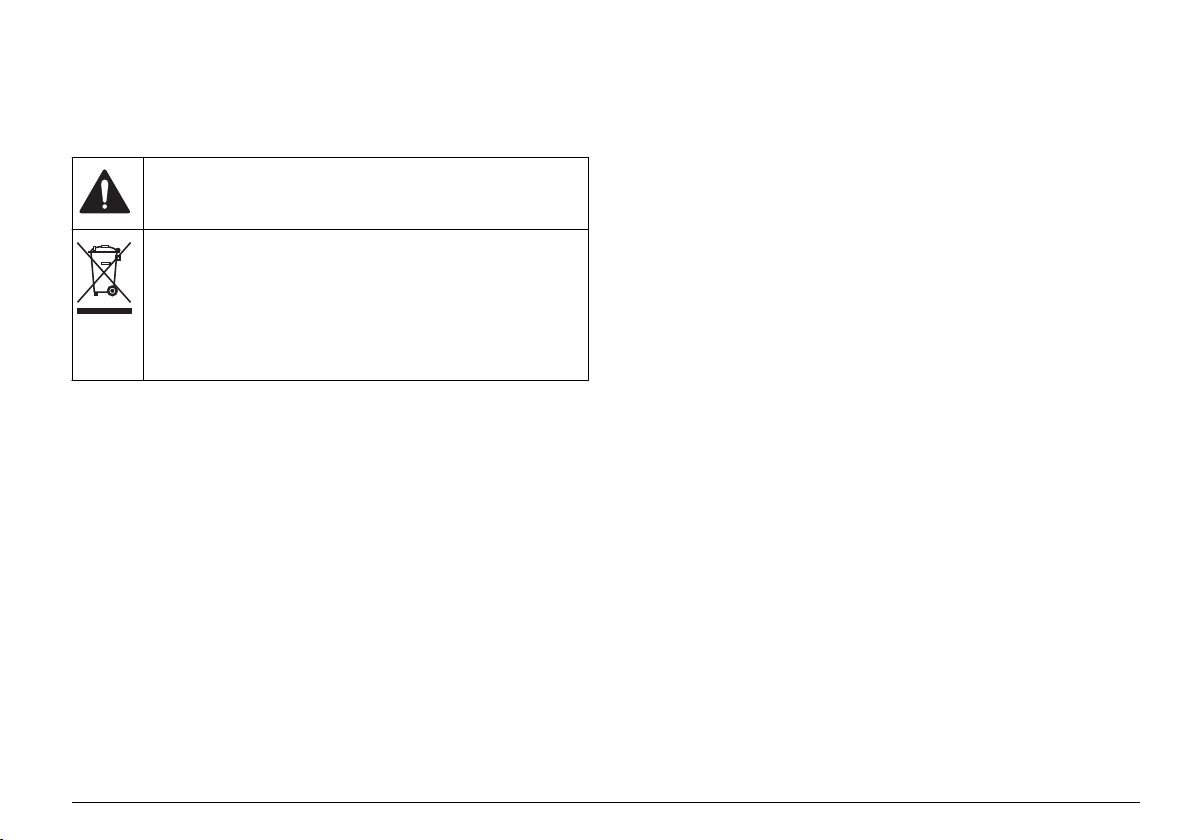
Precautionary labels
Read all labels and tags attached to the instrument. Personal injury or
damage to the instrument could occur if not observed. A symbol, if noted
on the instrument, will be included with a danger or caution statement in
the manual.
This symbol, if noted on the instrument, references the instruction
manual for operation and/or safety information.
Electrical equipment marked with this symbol may not be disposed of
in European public disposal systems after 12 August of 2005. In
conformity with European local and national regulations (EU Directive
2002/96/EC), European electrical equipment users must now return
old or end-of-life equipment to the Producer for disposal at no charge
to the user.
Note: For return for recycling, please contact the equipment producer or supplier
for instructions on how to return end-of-life equipment, producer-supplied
electrical accessories, and all auxiliary items for proper disposal.
Certification
Canadian Radio Interference-Causing Equipment Regulation,
IECS-003, Class A:
Supporting test records reside with the manufacturer.
This Class A digital apparatus meets all requirements of the Canadian
Interference-Causing Equipment Regulations.
Cet appareil numèrique de la classe A respecte toutes les exigences du
Rëglement sur le matériel brouilleur du Canada.
FCC Part 15, Class "A" Limits
Supporting test records reside with the manufacturer. The device
complies with Part 15 of the FCC Rules. Operation is subject to the
following conditions:
1. The equipment may not cause harmful interference.
2. The equipment must accept any interference received, including
interference that may cause undesired operation.
Changes or modifications to this equipment not expressly approved by
the party responsible for compliance could void the user's authority to
operate the equipment. This equipment has been tested and found to
comply with the limits for a Class A digital device, pursuant to Part 15 of
the FCC rules. These limits are designed to provide reasonable
protection against harmful interference when the equipment is operated
in a commercial environment. This equipment generates, uses and can
radiate radio frequency energy and, if not installed and used in
accordance with the instruction manual, may cause harmful interference
to radio communications. Operation of this equipment in a residential
area is likely to cause harmful interference, in which case the user will be
required to correct the interference at their expense. The following
techniques can be used to reduce interference problems:
1. Disconnect the equipment from its power source to verify that it is or
is not the source of the interference.
2. If the equipment is connected to the same outlet as the device
experiencing interference, connect the equipment to a different
outlet.
3. Move the equipment away from the device receiving the interference.
4. Reposition the receiving antenna for the device receiving the
interference.
5. Try combinations of the above.
Product overview
The 2100AN IS laboratory turbidimeter measures turbidity in FNUs
(Formazin nephelometric units), NTUs (nephelometric turbidity units) and
EBCs (European Brewing Convention units). NTUs and EBCs are
calculated using the conversion factors of 1.0 NTU per 1.0 FNU and
0.245 EBCs per 1.0 FNU. The 2100AN IS turbidimeter also measures
attenuation (FAU), absorbance and transmittance.
In addition, two user-defined measurement units can be specified. Refer
to Application specific methods on page 41. The application specific
mode of operation uses the nephelometric optical system and the NTU
measurement mode.
The turbidimeter has a built-in printer and an RS232 output for
connection to a printer, data logger or computer and a recorder output.
English
7
The turbidimeter contains a real-time clock with battery. The clock
provides a time-date stamp on all data transmitted to the built-in printer
or to external devices by way of the RS232 interface (i.e., measurements
and calibration records).
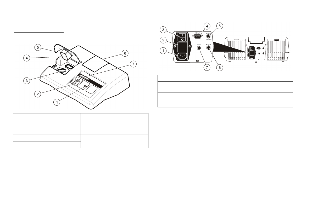
Figure 1 Front overview
Figure 2 Back overview
1 Power cord connector 5 Air purge fitting
2 Fuse holder 6 Recorder output jack for a chart
3 Power switch 7 Remote cable jack for flow valve
4 DB9 connector for RS232 cable
recorder (0 to 1 V output)
module connection to the automatic
flow cell (low pressure)
1 Mode display: shows the calibration
standard number, setup number or
sample number
2 Keypad 6 Printer cover
3 Sample cell holder 7 Eight-digit LED display
4 Light shield
5 Cover for the sample cell
compartment
8 English
Product components
Refer to Figure 3 to make sure that all components have been received.
If any of these items are missing or damaged, contact the manufacturer
or a sales representative immediately.
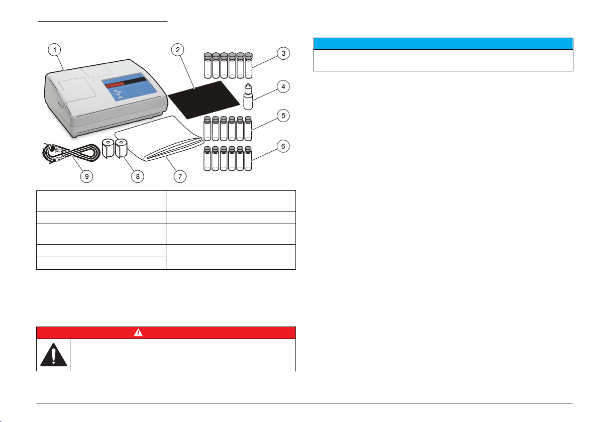
Figure 3 Instrument components
1 2100AN IS turbidimeter 6 Gelex® secondary turbidity
2 Oiling cloth 7 Dust cover
3 Six 1" sample cells (30 mL) with
caps
4 Silicone oil 9 Power cord
5 StablCal® Calibration kit
1
Supplied with 4790100 only.
2
Do not remove the plastic wrapper from the paper rolls until the paper is
installed.
standardization kit
8 Printer paper roll (2x)
1
2
Installation
Put paper in the printer
N O T I C E
Use only the provided thermal paper. Use of other thermal paper may cause poor
print quality and decrease the life of the print-head.
Notes:
• Do not rub the thermal paper with a hard object.
• Do not use chemical paste on thermal paper.
• A red line on the edge of the thermal paper shows when the paper
supply is low.
1. Cut the end of the paper with scissors to make an arrow shape.
2. Open the printer cover.
3. Put the point of the thermal paper in the paper entrance slot.
4. Push the paper through until the point of the paper comes out the
exit slot.
5. Pull the paper out of the exit slot until the full width of the paper is
past the exit slot.
6. Put the paper roll in the printer.
7. Put the thermal paper through the slot in the printer cover, then close
the printer cover.
D A N G E R
Multiple hazards. Only qualified personnel must conduct the tasks
described in this section of the document.
English 9
User interface
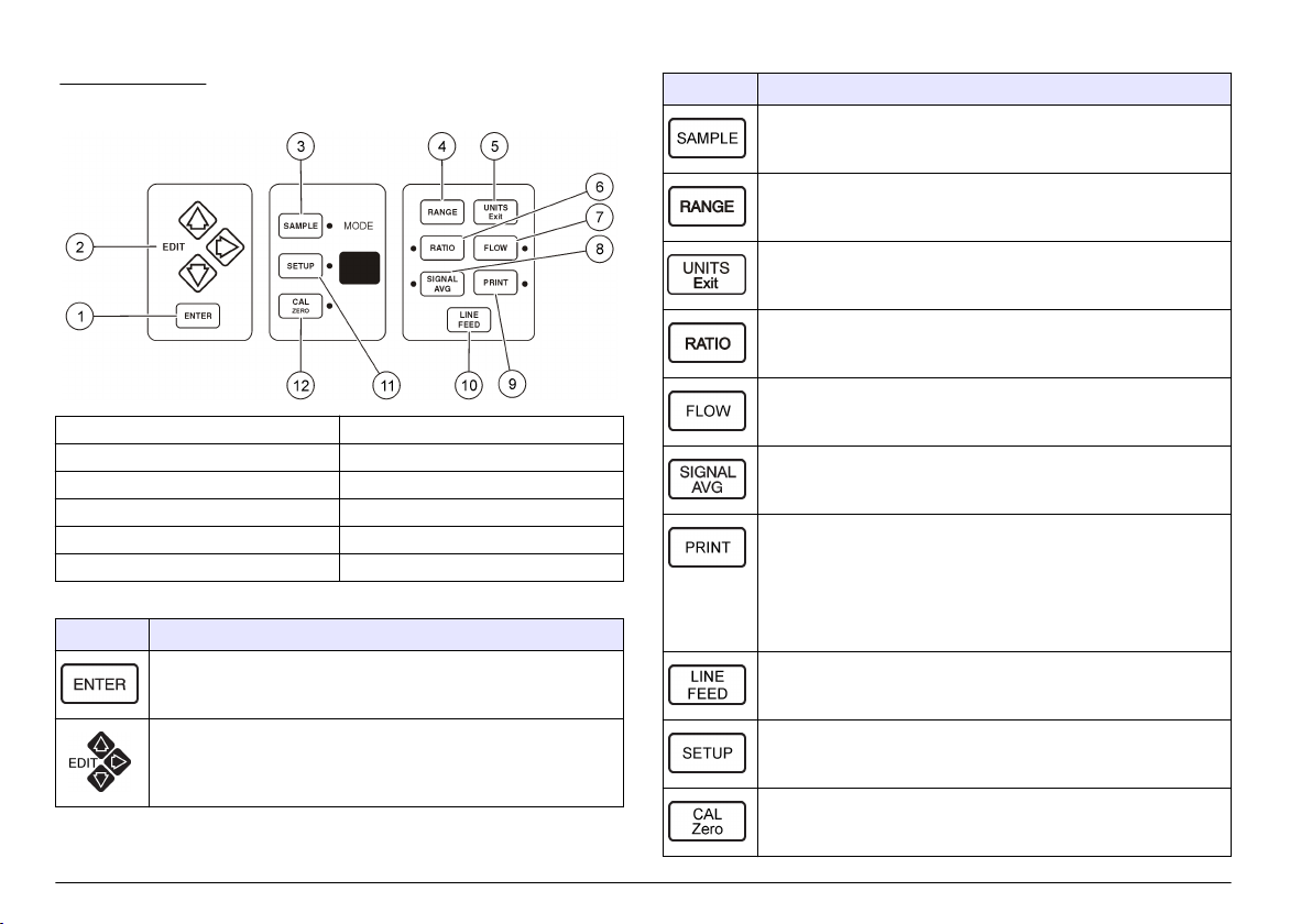
Figure 4 Keypad
1 ENTER key 7 FLOW key
2 EDIT (arrow) keys 8 SIGNAL AVG key
3 SAMPLE key 9 PRINT key
4 RANGE key 10 LINE FEED key
5 UNITS/Exit key 11 SETUP key
6 RATIO key 12 CAL/Zero key
Table 1 Key descriptions
Key Description
Enters the value on the display. Starts the measurement of a
calibration standard. Clears data from the buffer.
Table 1 Key descriptions (continued)
Key Description
Starts the changing of the sample number shown on the mode
display.
Selects automatic or manual ranging.
Selects the unit of measure. Exits Calibration or Setup mode
without saving changes.
Turns Ratio on or off.
Turns on or off the Flow mode of operation. Used only with the
automated flow cell.
Turns signal averaging on or off.
Sends the data that is on the display to a printer or computer.
Sends a calibration data report to a printer or computer when in
Calibration mode. Sends diagnostic results to a printer or computer
if held down when the instrument is turned on. Provides a print of
the setup commands when in Setup mode. Turns the print interval
feature on or off if the instrument has been configured with a printer
interval.
Moves the printer paper forward one line.
10 English
Changes the numbers and/or letters on the display. Steps through
the calibration standards. The right arrow key moves the cursor to
the previous or next digit.
Turns on Setup mode and starts the selection of the setup number
on the mode display.
Starts a calibration when in FNU, FAU, NTU or EBC mode. Starts
analytical zeroing when in %T or Abs mode.
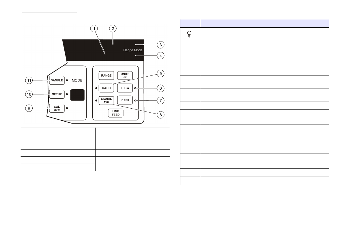
Figure 5 Indicator lights
1 Lamp icon light 7 PRINT light
2 "CAL?" light 8 SIGNAL AVG light
3 "Manual" light 9 CAL/Zero light
4 "Auto" light 10 SETUP light
5 RATIO light 11 SAMPLE light
6 FLOW light
Table 2 Light descriptions
Light Description
Illuminated when the instrument light source is on.
Flashes when there is not sufficient light for measurement.
CAL? "CAL?" is shown during a calibration if the calibration data is not
within the acceptable range.
Flashes when the instrument should be calibrated.
Note: The CAL? light applies when a 25-mm sample cell is used. Ignore the
CAL? light if illuminated during calibration when a smaller sample cell is used.
Push UNITS/Exit to start measurements.
Manual "MANUAL" is shown above the Range Mode label when the
RATIO Illuminated when Ratio is on.
FLOW Illuminated when the Flow mode of operation is selected.
PRINT Illuminated when the printer interval feature is selected.
SIGNAL
SETUP Illuminated when Setup mode is selected.
SAMPLE Illuminated when Sample mode is selected.
instrument is in manual ranging mode.
Auto "AUTO" is shown below the Range Mode label when the instrument is
in auto ranging mode.
Flashes when the flow cycle is done.
Flashes when a print interval has been selected but is not active.
Illuminated when signal averaging is on.
AVG
CAL
Illuminated when Calibration or Zeroing mode is selected.
Zero
English 11

Startup
Set the date and time
Turn the instrument on
C A U T I O N
Infrared Light Hazard. The infrared light produced by this instrument can cause
eye injury. The infrared light source in this instrument only receives power when
the sample cell cover is closed.
1. Put the instrument on a stable, level surface that is free of vibration.
Do not put in direct sunlight.
2. Make sure that there is air circulation around the instrument. Keep
the back and area below the instrument free of material that could
decrease air flow through the vents.
3. Connect the power cord to the power plug on the back of the
instrument.
4. Connect the power cord to a power socket with ground contact.
5. Push the power switch on the back of the instrument to turn the
instrument on.
Turn the keypad sound off (optional)
By default, the instrument makes an audible sound when a key is
pushed. To turn the keypad sound off:
1. Push SETUP. The SETUP light turns on.
2. Use the arrow keys to select 00.
3. Push ENTER.
4. Use the arrow keys to select the sound option:
Option Description
BEEP ON An audible sound is made when a key is pushed.
BEEP OFF No sound is made when a key is pushed.
5. Push ENTER.
6. Push SETUP.
1. Push SETUP. The SETUP light turns on.
2. Use the arrow keys to select an option:
Option Description
05 Sets the hours and minutes (HH-MM).
06 Sets the month and day (MM-DD).
07 Sets the year (YY).
3. Push ENTER.
4. Use the arrow keys to change the value.
5. Push ENTER.
6. Push SETUP.
Show the current time (optional)
1. Push SETUP. The SETUP light turns on.
2. Use the arrow keys to select 08.
3. Push ENTER. The current time is shown on the display (HH-MM-
SS).
4. Push SETUP.
Standard operation
Calibrate the turbidimeter with StablCal® Standards
Calibrate the turbidimeter before it is used for the first time using the
StablCal® sealed vial standards provided. As an alternative, calibration
can be done with recently prepared formazin standards. Refer to
Calibrate the turbidimeter with formazin standards on page 37.
Calibrate the turbidimeter at least every 3 months or as specified by the
regulating authority when data is used for ISO 7027 reporting.
Note: Unknown results may occur if standards other than the recommended
calibration points are used. The recommended calibration points (< 0.1, 20, 200,
1000, 4000 and 7500 NTU) provide the best calibration accuracy. Use of standards
12
English

other than StablCal, or user-prepared formazin, may result in less accurate
calibrations. The manufacturer cannot guarantee the performance of the instrument
if calibrated with co-polymer styrenedivinylbenzene beads or other suspensions.
Prepare the StablCal standards
When received and at intervals:
1. Clean the exterior surface of the StablCal vials with laboratory glass
cleaning detergent.
2. Rinse the vials with distilled or deionized water.
3. Dry the vials with a lint-free cloth.
Note: Never shake or invert the < 0.1 NTU standard. If the standard has been
mixed or shaken, do not move the vial for 15 minutes or more before using.
Note: Do not remove the caps from the sealed vials.
Make sure that the StablCal standards are at ambient instrument
temperature before use (and no greater than 40 °C (104 °F)).
Mix the standards before use:
1. Open the case lid. Remove the < 0.1 NTU standard from the plastic
case.
2. Leave the other standards in the case. Close the case lid.
3. Shake the case vigorously for at least 10 seconds.
4. Let the standards stand with no movement for 3–5 minutes before
use.
Calibration notes
• Make sure that the instrument is in the same ambient conditions as
where it is used.
• Make sure that the standards are at the same ambient temperature as
the instrument before use.
• Use only the provided silicone oil. This silicone oil has the same
refractive index as the vial glass and masks minor glass differences
and scratches.
• Store the oiling cloth in a plastic storage bag to keep the cloth clean.
• If power is lost during calibration, the new calibration data is lost and
the last calibration data is used. To exit a calibration and not save the
new values, push UNITS/Exit.
• In Calibration mode, automatic range and signal averaging on are
selected. When calibration is completed, all operational modes go
back to the last settings.
• All nephelometric (turbidity units of measure) calibrations are done at
the same time.
• Ratio-on and Ratio-off calibration data is measured and recorded at
the same time.
• The 4000-NTU and 7500-NTU standards do not have to be measured
during calibration if FNUs will be measured. Push CAL/Zero after the
1000 NTU standard is measured to complete the calibration
procedure.
• The 7500-NTU standard does not have to be measured during
calibration if turbidity less than 4000 NTU will be measured. Push
CAL/Zero after the 4000 NTU standard is measured to complete the
calibration procedure.
• The FNU values of StablCal standards and formazin standards are
calculated using the conversion factors of 1 FNU = 1 NTU.
English 13
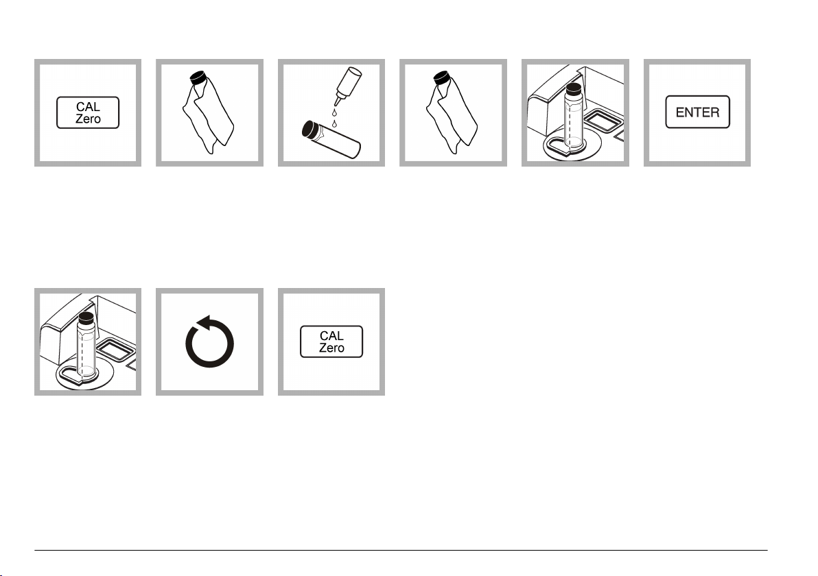
StablCal calibration procedure
1. Push CAL/Zero.
The CAL/Zero light
turns on, and the mode
display shows "00". The
NTU value of the
dilution water that was
used in the previous
calibration is shown on
the display.
7. Remove the vial
from the sample cell
holder.
14 English
2. Get the < 0.1 NTU
vial. Clean the vial with
a soft, lint-free cloth to
remove water spots and
fingerprints. Do not
invert the vial.
8. Do steps 5–10 for
the other StablCal vials
(from lowest to highest
NTU standard).
The mode display
shows "00" after the
last vial is measured.
3. Apply a small bead
of silicone oil from the
top to the bottom of the
vial.
9. Push CAL/Zero.
The instrument saves
the new calibration data
and goes back to
Measurement mode.
4. Use the oiling cloth
to apply the oil equally
to the surface of the
vial. Remove the
excess oil. Make sure
that the vial is almost
dry.
5. Put the vial in the
sample cell holder with
the triangle on the vial
aligned with the
reference mark on the
sample cell holder.
Close the cover.
6. Push ENTER.
The instrument display
counts down, then
measures the standard.
The next expected
standard (e.g., 20.00) is
shown. The mode
display shows "01".

StablCal standards storage
instrument due to small differences in glass and instrument optical
systems.
• Do not move a StablCal standard to a different container for storage.
Keep StablCal standards in the plastic case provided with the cover
closed.
• Store at 5 to 25 °C (41 to 77 °F).
• For long-term storage (more than one month between use), keep at
5 °C (41 °F).
• Do not keep a Gelex vial in the instrument for more time than is
necessary to complete measurement. The heat from the lamp can
change the turbidity value of a Gelex vial.
• Keep the Gelex standards at room temperature. Do not let Gelex
standards freeze or become warmer than 50 °C (122 °F). High
temperatures may cause Gelex suspensions to divide.
• Make sure that the Gelex standards are at ambient instrument
Using Gelex secondary standards
temperature before measurement.
The Gelex secondary standards are used when a calibration check or an
optical system check is done. Refer to Calibration verification
on page 17 and Optical system check on page 17.
Gelex notes
• Measure the Gelex secondary standards on the instrument on which
they will be used. The measured values can only be used for one
Measure the Gelex stray light standard
Measure the Gelex stray light standard when the instrument is first received. Record the value on the Gelex vial with a permanent marker one time.
1. Clean the stray light
standard with a soft,
lint-free cloth to remove
water spots and
fingerprints.
2. Apply a small bead
of silicone oil from the
top to the bottom of the
vial.
3. Use the oiling cloth
to apply the oil equally
to the surface of the
vial. Remove the
excess oil. Make sure
that the vial is almost
dry.
4. Push RANGE to
select automatic
ranging.
"AUTO" is shown below
the Range Mode label
on the instrument.
5. Push SIGNAL AVG
to turn signal averaging
off.
The SIGNAL AVG light
turns off.
6. Push UNITS/Exit to
select the NTU
measurement mode.
English 15

7. Push RATIO to turn
Ratio mode on.
8. Put the stray light
standard in the sample
cell holder with the
triangle on the vial
aligned with the
reference mark on the
sample cell holder.
Close the cover.
9. Read the value
when stable. Remove
the vial from the
instrument.
10. Record the value
on the white diamond
space on the vial using
a permanent marker.
Measure the Gelex secondary turbidity standards
Measure the Gelex secondary turbidity standards each time the instrument is calibrated and record the new values on the Gelex vials with a water
soluble marker.
1. Clean the Gelex
vials with a soft, lint-free
cloth to remove water
spots and fingerprints.
16 English
2. Apply a small bead
of silicone oil from the
top to the bottom of the
vial.
3. Use the oiling cloth
to apply the oil equally
to the surface of the
vial. Remove the
excess oil. Make sure
that the vial is almost
dry.
4. Push RANGE to
select automatic
ranging.
"AUTO" is shown below
the Range Mode label
on the instrument.
5. Push SIGNAL AVG
to turn signal averaging
off.
The SIGNAL AVG light
turns off.
6. Push UNITS/Exit to
select the NTU
measurement mode.

7. Push RATIO to
select Ratio on or off.
Ratio must be on for
Gelex standards
greater than 40 NTU.
For the 0–2 and 0–
20 NTU Gelex
standards, select the
Ratio function that the
instrument will operate
in.
8. Put the 0–2 NTU
Gelex vial in the sample
cell holder with the
triangle on the vial
aligned with the
reference mark on the
sample cell holder.
Close the cover.
9. Read the value
when stable. Remove
the vial from the
instrument.
10. Record the value
on the white diamond
space on the vial using
a water soluble marker.
Record on the vial if
Ratio was on or off
when the vial was
measured.
11. Do steps 7–10 for
the other Gelex vials
(but not the stray light
standard). Measure
from lowest to highest
NTU.
Calibration verification
At intervals, measure the Gelex secondary turbidity standard that is
closest in value to the turbidity range to be measured. Do the steps in
Measure the Gelex secondary turbidity standards on page 16, but do not
change the value that is recorded on the vial.
Turn Ratio on if the Gelex vial is greater than 40 NTU. Select the Ratio
setting recorded on the Gelex vial for vials less than 40 NTU.
If the measured value is within ±5% of the value recorded on the Gelex
vial, calibration is verified. If not, calibrate the instrument.
Note: The StablCal® primary turbidity standards can also be used to do a
calibration check. Prepare the StablCal vials before use. Refer to Prepare the
StablCal standards on page 13. Do not use the < 0.1 NTU StablCal vial as it does
not have an accurately identified NTU value. The instrument is calibrated if the
measured value is within ±5% of the StablCal value.
Optical system check
At intervals, measure the Gelex stray light standard to inspect the
integrity of the optical system. Do the steps in Measure the Gelex stray
light standard on page 15, but do not change the value that is recorded
on the vial.
If the value measured is similar to the value recorded on the Gelex stray
light standard (within ±0.02 NTU), the instrument works correctly. If not,
contact Customer Service.
Prepare a sample cell
Use a clean sample cell(s) for sample measurement.
Note: As an alternative, a flow cell can be used for sample measurement. Refer to
Using a flow cell on page 30.
English 17

Clean the sample cell
C A U T I O N
Chemical exposure hazard. Obey laboratory safety procedures and
wear all of the personal protective equipment appropriate to the
chemicals that are handled. Refer to the current material safety data
sheets (MSDS) for safety protocols.
N O T I C E
Do not air dry the sample cells. Always store the sample cells with caps on to
prevent the cells from drying. For storage, fill the sample cell with distilled or
demineralized water.
1. Clean the internal and external surfaces of the sample cell and cap
with a laboratory glass cleaning detergent.
2. Fully rinse the sample cell many times with distilled or deionized
water.
3. Clean the internal and external surfaces of the sample cell and cap
with 1:1 hydrochloric acid.
4. Fully rinse the sample cell many times with distilled or deionized
water.
Note: If the sample cell will be used to measure low range turbidity samples or
dilution water, rinse with dilution water (not distilled or deionized water). Refer
to Prepare dilution water on page 23.
5. Dry the external surface of the sample cell with a soft, lint-free cloth.
6. Fill the sample cell with distilled or deionized water.
Note: If the sample cell will be used to measure low range turbidity samples or
dilution water, fill the sample cell with dilution water (not distilled or deionized
water).
7. Immediately put the cap on the sample cell.
Note: Hold the sample cell by the top only to minimize dirt and fingerprints.
18 English

Indexing a single sample cell
When measuring very low turbidity samples, use a single indexed sample cell or a flow cell for all measurements to get precise and repeatable
measurements. As an alternative, optically matched sample cells can be used. Refer to Matching sample cells on page 21. Matched sample cells do
not provide as good of accuracy and precision as a single indexed sample cell that is used for every measurement or a flow cell.
1. Rinse a clean,
empty sample cell two
times with dilution water
and drain to waste. Fill
the sample cell to the
line (about 30 mL) with
dilution water and
immediately put the cap
on the sample cell.
Refer to Prepare
dilution water
on page 23.
Let the sample cell sit
for at least five minutes
to degas.
2. Clean the sample
cell with a soft, lint-free
cloth to remove water
spots and fingerprints.
3. Apply a small bead
of silicone oil from the
top to the bottom of the
sample cell.
4. Use the oiling cloth
provided to apply the oil
equally to the surface of
the sample cell.
Remove the excess oil.
Make sure that the
sample cell is almost
dry.
5. Put the sample cell
in the sample cell
holder. Close the cover.
Record the value when
stable.
6. Remove the sample
cell, turn it about 1/8 of a
turn and put it in the
sample cell holder
again. Close the cover.
Record the value when
stable.
English 19

7. Repeat step 6 until
the lowest value is
shown on the display.
8. Put an orientation
mark on the marking
band near the top of the
sample cell where the
lowest value is shown.
20 English

Matching sample cells
To decrease the effects that optical differences among sample cells can have on turbidity, transmittance or absorbance measurements, measure
samples in matched sample cells. It may not be possible to match all sample cells due to the differences in glass.
1. Rinse two or more
clean, empty sample
cells two times with
dilution water and drain
to waste. Fill the
sample cells to the line
(about 30 mL) with
filtered dilution water
and immediately put the
cap on the sample cell.
Refer to Prepare
dilution water
on page 23.
Let the sample cell sit
for at least five minutes
to degas.
2. Clean the sample
cells with a soft, lint-free
cloth to remove water
spots and fingerprints.
Do not invert the
sample cell.
3. Apply a small bead
of silicone oil from the
top to the bottom of the
sample cells.
4. Use the oiling cloth
provided to apply the oil
equally to the surface of
the sample cells.
Remove the excess oil.
Make sure that the
sample cells are almost
dry.
5. Put the first sample
cell in the sample cell
holder. Close the cover.
Record the value when
stable.
6. Remove the sample
cell, turn it about 1/8 of a
turn and put it in the
sample cell holder
again. Close the cover.
Record the value when
stable.
English 21

7. Repeat step 6 until
the lowest value is
shown on the display.
13. Do steps 9–
12 again as necessary
to match the other
sample cells prepared
in steps 1–4.
8. Record the value.
Put an orientation mark
on the marking band
near the top of the
sample cell.
9. Put the second
sample cell in the
sample cell holder.
Close the cover.
Record the value when
stable.
10. Remove the
sample cell, turn it
about 1/8 of a turn and
put it in the sample cell
holder again. Close the
cover.
Record the value when
stable.
11. Repeat step
10 until the value
matches the first
sample cell value within
±0.005 FNU.
Note: Match sample
cells to within
±0.002 absorbance
units when indexing
sample cells in the
Absorbance mode for
use with transmittance
or absorbance
measurements.
12. Put an orientation
mark on the marking
band near the top of the
sample cell where the
lowest value is shown.
22 English

Prepare dilution water
Dilution water is used when indexing a sample cell or matching sample
cells and to prepare formazin standards.
1. Collect at least 1000 mL of high-quality, low-turbidity water (i.e.,
distilled, demineralized or deionized water or filtered tap water).
2. Measure the turbidity of the water using the turbidimeter. Refer to
Turbidity measurement on page 25.
3. If the turbidity of the water is greater than 0.5 NTU, filter the water
using the sample filtration and degassing kit. Refer to the user
instructions provided with the sample filtration and degassing kit.
Prepare the sample
Proper sampling techniques are important to get accurate
measurements.
Prepare a representative sample
A representative sample accurately reflects the true condition of
the water source from which the sample was taken.
To prepare a representative sample:
• Gently but fully mix every sample before collecting aliquots (sample
portions). Mix by gentle inversion only. Do not shake.
• When collecting a sample from a water tap in a distribution system or
treatment plant, turn the water on for at least five minutes, then collect
the sample.
• When collecting a sample from a body of water (e.g., a stream or
storage tank), collect at least one liter (1 quart) and fully mix before
taking an aliquot for measurement. If the quality of the sample source
is not constant, collect samples at many locations at different depths
as necessary. Then, mix the samples together to prepare one sample
for measurement.
Remove air bubbles from the sample
If readings are not stable, air bubbles may be the cause. Remove air or
other gases from the sample before measurement even if no bubbles
can be seen.
The methods typically used for degassing are:
• Let the sample stand for several minutes
• Apply a vacuum
• Use an ultrasonic bath
• Apply heat
Let the samples stand for several minutes, then gently invert two or three
times before measurement.
In some cases, more than one method may be necessary to remove
bubbles (e.g., the use of heat with an ultrasonic bath may be necessary
in some severe conditions). Use care with these methods as sample
turbidity can be changed if these methods are not used correctly.
Apply a vacuum
Apply a vacuum with any available, clean, oil-free vacuum source, such
as the sample degassing kit, or an electric or hand-operated pump
equivalent to those in Accessories on page 46. The vacuum lowers the
atmospheric pressure above the sample letting trapped gas bubbles exit.
Vacuum works well with samples that are not viscous, such as water,
and do not contain volatile components. Application of vacuum to
viscous, volatile samples (i.e., paint resins) may cause volatile
components to come out of solution, and increase the bubbles.
Use an ultrasonic bath
An ultrasonic bath removes gas bubbles from most samples, especially
viscous liquids. The time necessary to remove bubbles may be a few
seconds to a minute or more.
To identify the time necessary for ultrasonic treatment:
1. Apply ultrasound to the sample for a short period of time, then
measure turbidity. Record the value and the treatment time.
2. Do step 1 again until there is no change in the turbidity of the
sample.
Note: In some instances, the use of ultrasound may divide gas bubbles and make
them more difficult to remove.
To use an ultrasonic bath:
1. Fill a clean sample cell with sample. Do not put the cap on the
sample cell.
English
23

2. Put 1/2 to 2/3 of the sample cell into the ultrasonic bath and let it stand
until visible bubbles are removed.
3. Remove the sample cell from the ultrasonic bath and put the cap on.
4. Fully dry the sample cell.
Apply heat
C A U T I O N
Make sure that the cap on the sample cell is loose. Increasing the temperature of
a tightly-capped sample cell may cause an explosion. More caution should be
taken when increasing the temperature of volatile compounds.
If possible, do not use heat to accelerate degassing. Heat may change
the properties of the suspended particles and cause volatile components
to come out of the solution.
Gentle heat may be used to remove bubbles from very viscous samples
when used with vacuum or ultrasound. If applying heat to the sample is
necessary, do so only as much as is necessary to complete degassing.
Before measurement, decrease the temperature of the sample to the
initial temperature, then gently invert the sample.
Prevent condensation on a sample cell
Condensation may occur on the outside of the sample cell when
measuring a cold sample in a warm, humid environment. This
condensation or fogging of the sample cell interferes with turbidity
measurement.
To prevent condensation:
• Make sure that the outside of the sample cell is dry before
measurement.
• Use the air purge system as necessary. Refer to Using the air purge
system on page 29.
• If condensation occurs while using the air purge system, warm the
sample slightly. Let the sample sit at room temperature or partially put
the sample into a warm water bath for a short time. Gently invert the
sample cell before measurement.
Note: Warming may change the sample turbidity. Measure the sample without
warming when possible.
Measure over-range samples
The nephelometric method of turbidity measurement depends on light
scattering from suspended particles. If turbidity is very high, significant
amounts of light may be absorbed by the particles, and little light is
available for scattering. This results in a negative interference causing
the measured turbidity to be lower than the actual turbidity. This
condition is called “going blind”.
Methods used to prevent the instrument from going blind include:
• Turn Ratio on. Ratio on mode decreases the effects of light absorbing
particles, color, absorbance and high turbidity interferences.
• If measuring in the FNU mode, change the measurement units to NTU
by pushing UNITS/Exit. The NTU measurement mode (with Ratio on)
increases the measurement range.
• Sample dilution. Refer to Sample dilution on page 24.
When too much light is absorbed by the sample, the lamp icon on the
instrument display flashes.
Sample dilution
Use filtered sample, deionized water or distilled water for sample
dilution. Measure sample dilutions soon after they are prepared.
To prepare filtered sample, use the sample filtration and degassing kit.
Refer to the user instructions provided with the sample filtration and
degassing kit.
If the filters in the sample filtration and degassing kit plug quickly, use a
standard 47 mm filtration apparatus shown in Figure 6 with a membrane
filter or use a glass-fiber filter. Refer to Accessories on page 46.
After dilution and measurement, calculate the actual turbidity as follows:
1. Calculate the total volume:
Total volume = sample + dilution water
Example: 20 mL of sample and 80 mL of dilution water
Total volume = 20 mL + 80 mL = 100 mL
2. Calculate the dilution factor:
Dilution factor = total volume ÷ sample volume
Example: Dilution factor = 100 ÷ 20 = 5
24
English
3. Calculate the actual turbidity:
Actual turbidity = measured value × dilution factor
Example: Measured value = 2450 NTU
Actual turbidity = 2450 × 5 = 12,250 NTU
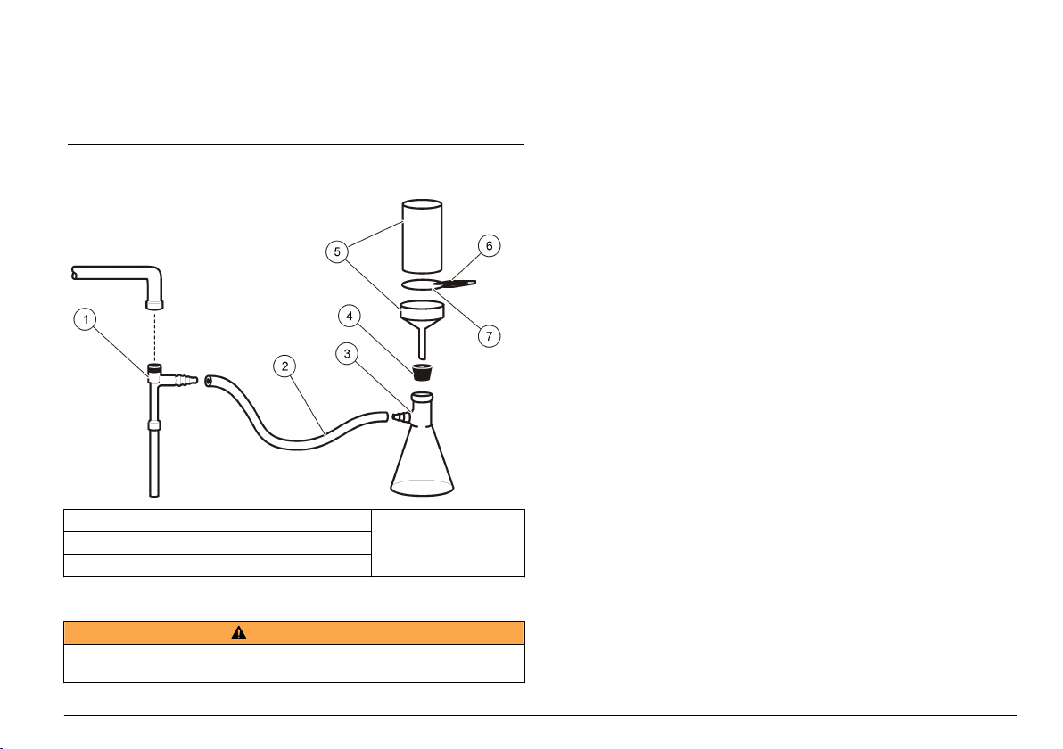
Figure 6 Prepare filtered sample using membrane or glass-fiber
filter
1 Filter pump 4 Stopper 7 Filter
2 Hose 5 Filter holder
3 Filter flask 6 Tweezers
Turbidity measurement
W A R N I N G
Potential explosion and fire hazard. This instrument is for measuring water based
samples. Do not measure solvent or combustible based samples.
For accurate turbidity readings use clean sample cells and remove air
bubbles. Refer to Clean the sample cell on page 18 and Remove air
bubbles from the sample on page 23.
Measurement notes
Proper measurement techniques are important in minimizing the effects
of instrument variation, stray light and air bubbles. For accurate and
repeatable measurements:
Instrument
• Make sure that the instrument is on a level, stationary surface that is
free of vibration during the measurement.
• Instrument stabilization is immediate. No warm-up time is necessary.
• Always close the sample compartment lid during measurement,
calibration and storage.
• Remove the sample cell from the instrument and turn off the
instrument if the instrument is stored for an extended time period
(more than a month).
• Keep the sample compartment lid closed to keep dust and dirt out.
Sample cells
• Always cap the sample cell to prevent spillage of the sample into the
instrument.
• Always use clean sample cells in good condition. Dirty, scratched or
damaged cells can result in readings that are not accurate.
• Make sure that cold samples do not “fog” the sample cell. Refer to
Prevent condensation on a sample cell on page 24.
• Store sample cells filled with distilled or deionized water and cap
tightly.
• For the best accuracy, use a single sample cell for every
measurement or a flow cell.
Note: As an alternative, matched sample cells may be used for measurements but
do not provide as good of accuracy or precision as a single indexed sample cell or
flow cell. When using matched sample cells, align the orientation mark on the
sample cell with the reference mark on the sample cell holder.
Measurement
English
25

• Measure samples immediately to prevent temperature changes and
settling. Before a measurement is taken, always make sure that the
sample is homogeneous throughout.
Turbidity measurement procedure
• Avoid sample dilution when possible.
• Avoid instrument operation in direct sunlight.
1. Rinse a clean,
empty sample cell two
times with the solution
to be measured and
drain to waste. Fill to
the line (about 30 mL)
with sample and
immediately put the cap
on the sample cell.
7. Read and record the
value when stable.
Note: To print or send
(via RS232) a
measurement record,
push PRINT.
26 English
2. Clean the sample
cells with a soft, lint-free
cloth to remove water
spots and fingerprints.
3. Apply a small bead
of silicone oil from the
top to the bottom of the
sample cells.
4. Use the oiling cloth
provided to apply the oil
equally to the surface of
the sample cells.
Remove the excess oil.
Make sure that the
sample cells are almost
dry.
5. Gently and slowly
invert the sample cell to
fully mix the sample. Be
careful not to add air
bubbles.
6. Put the sample cell
in the sample cell
holder with the triangle
on the sample cell
aligned with the
reference mark on the
sample cell holder.
Close the cover.
Absorbance and transmittance measurement
Measurement notes
For the best accuracy and reproducibility:
• Absorbance and transmittance can only be measured at 860 nm.
• Set the zero reference point before measurement. Set the zero
reference point again when a measurement is not taken for several
hours as shown in Absorbance and transmittance measurement
procedure on page 27.
• Transmittance and absorbance measurements use the same zero
single sample after setting a zero reference point in one of the two
modes.
• Use a flow cell for measurements. A flow cell is necessary to get the
accuracy and reproducibilty specifications shown in Specifications
on page 5.
If a flow cell is not used, use a single indexed sample cell or match
sample cells. Sample cells should be matched using the
Transmittance or Absorbance modes. Refer to Matching sample cells
on page 21.
• Refer to Measurement notes on page 25 for more measurement
notes.
reference point. Absorbance and transmittance can be measured on a
Absorbance and transmittance measurement procedure
Note: To measure samples with negative absorbance, set the analytical zero using the sample with the greatest absorbance, and measure the sample with the least
absorbance. Report the reading as negative absorbance.
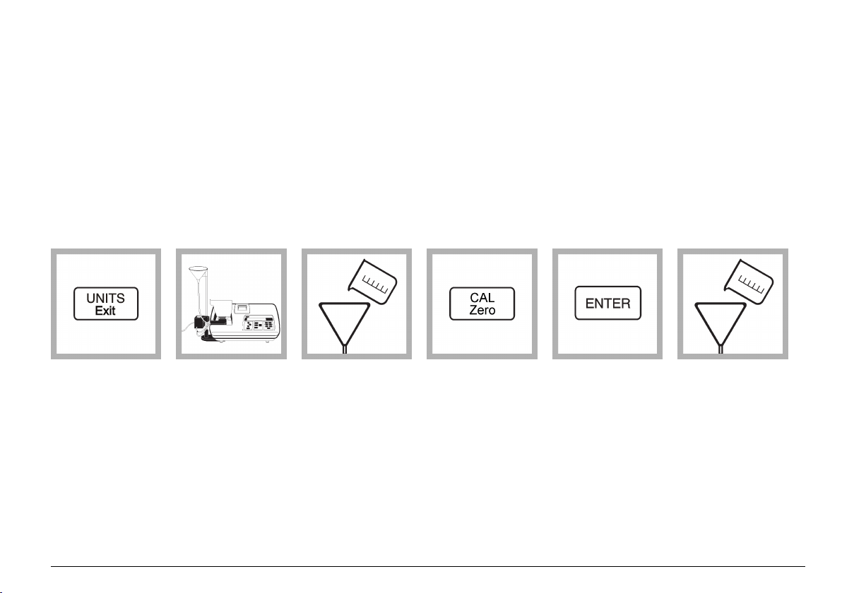
1. Push UNITS/Exit
until "%T" or "ABS" is
shown on the display.
2. Using the manual
flow cell kit, install the
flow cell. Refer to Using
a flow cell
on page 30.
Note: The sample cell
cover does not close
when the flow cell is
installed.
3. Slowly put 250 mL of
100 %T or zero
absorbance reference
solution down the
interior edge of the inlet
reservoir.
Put the sample down
the interior edge of the
reservoir to prevent air
bubbles in the sample.
4. Push CAL/Zero.
The display shows
"100 %T" or zero.
Note:
The instrument starts
analytical zeroing for
transmittance, and
absorbance modes at
the same time.
5. Push ENTER.
The instrument display
counts down from 30 to
0.
Note: If the value
shown is not 100 %T,
0.000 A, or if dashes
flash, do steps 5 and
6 again.
6. Slowly put 250 mL of
the sample in the inlet
reservoir.
English 27

7. After the sample
flow stops and the
display stabilizes, read
and record the value.
Note: To print or send
(via RS232) a
measurement record,
push PRINT.
Measurement techniques
Measurements may be made with different operation mode settings and
optional accessories.
Calibrate the instrument whenever the sample cell pathlength is
changed.
Manual or automatic ranging
The manufacturer recommends that ranging be set to automatic for most
measurements.
The setting can be changed at any time during sample measurement.
Push RANGE repeatedly to step the instrument from automatic ranging
to manual ranging and then scroll through the manual range settings.
"MANUAL" is shown above the Range Mode label on the instrument
when manual ranging is selected. "AUTO" is shown below the Range
Mode label on the instrument when automatic ranging is selected.
Notes:
• When manual ranging is selected, the display flashes all 9s when the
sample being measured is greater than the selected range. The
28 English
display flashes all 0s when the sample measured is less than the
selected range.
• When automatic ranging is selected, the display flashes 9s when the
sample is greater than the maximum range of the instrument. The
display flashes 9s when Ratio is off and the measurement is greater
than 40 NTUs (1000 FNUs or 9.8 EBCs). Turn Ratio on to increase
the range. Refer to Measure over-range samples on page 24.
• When automatic ranging is selected, the display flashes all 0s when
the measurement is less than the range of the instrument (i.e., less
than 20 FAU) or a negative value. Calibrate the instrument. When
measuring absorbance or transmittance, set the zero reference point
again.
Signal averaging on or off
Signal averaging corrects for reading fluctuations that are caused by
random drifting particles in the sample. When signal averaging is on, an
average reading is calculated every 3 seconds and shown on the
display.
The manufacturer recommends that signal averaging be on for most
measurements.
Push SIGNAL AVG to turn signal averaging on or off. The SIGNAL AVG
light turns on when signal averaging is on.
Push ENTER when signal averaging is on to erase data in the signal
averaging buffer and provide an immediate update on the display as
necessary. This is especially useful when measuring samples with large
differences in turbidity.
To change the number of measurements that are used to calculate the
average reading (default=10):
1. Push SETUP. The SETUP light turns on.
2. Select 09 using the arrow keys.
3. Push ENTER.
4. Use the arrow keys to select the number of measurements—1 to 15.
Note: If a number greater than 15 is selected, 15 measurements will be used.
5. Push ENTER.
6. Push SETUP.
Ratio on or off
Ratio on provides very good linearity, calibration stability and a wide
measurement range. Ratio on helps correct for interference when color
is present in the sample that absorbs at the wavelength of incident light.
The manufacturer recommends that Ratio on be used for most
measurements. Ratio must be on to measure samples greater than
40 NTUs (9.8 EBCs).
Ratio can be turned on for NTU, EBC and ASC -1- and -2measurements.
Push RATIO to turn Ratio on or off. The Ratio light is on when Ratio is
on.
Notes:
• If the sample being measured is greater than 40 NTU (or equivalent)
and Ratio is off, the display will show 9s and the RATIO light will flash.
Push RATIO to turn Ratio on and remove the over-range condition.
• Measurements with Ratio on and measurements with Ratio off are
almost the same for turbidity measurements that are less than 40 NTU
if interferences caused by color or light absorbing particles are not
present.
Using the air purge system
The air purge system is used to keep condensation off the external
surface of the sample cell when cold samples are measured.
The air purge system pushes dry air through the optical compartment to
keep the outside the sample cell dry. The connection is made at the air
purge fitting on the back of the instrument Figure 2 on page 8.
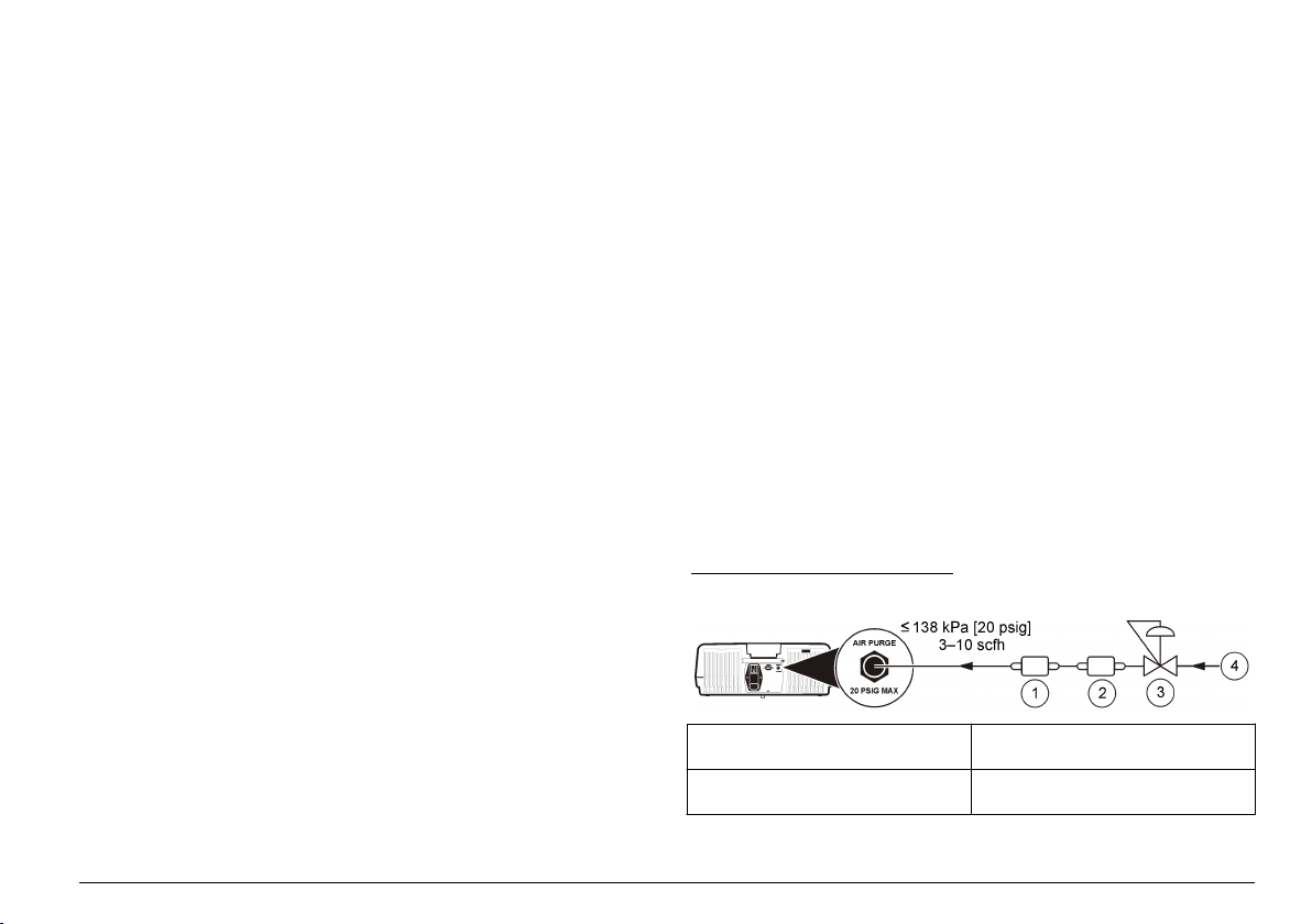
Use dry nitrogen or instrument grade air (ANSI MC 11.1, 1975) at no
greater than 138 kPa (20 psig). The manufacturer recommends an air
consumption rate of 3 to 10 SCFH (standard cubic feet/hour).
When the sample temperature is about or less than 2 °C (35 °F), use a
desiccant dryer and particle filter to make sure that the dew point of the
air purge is less than the sample temperature. The air dryer contains
silica gel desiccant that turns pink. Replace the desiccant when it turns
pink.
If only shop air is available, use a coalescing filter with an automatic
drain and a dryer and particle filter to get instrument quality air. Use a
coalescing filter that typically operates for greater than 2000 hours.
Replace the particle filter when the air dryer is replaced.
Figure 7 and Figure 8 show the methods for connecting the two types of
air supply to the instrument.
Note: The dryer and filter are not necessary if dry nitrogen is used.
Figure 7 Instrument quality air
1 Particle filter (Balston DFU 9933-
05-BQ or equivalent)
2 Air dryer (Balston DAU 9933-
05-101 or equivalent)
3 Pressure regulator
4 Instrument air
English 29

Figure 8 Standard shop air
1 Particle filter 5 Filter (Balston 100-12-BX or
2 Air dryer 6 Auto drain (Balston 20-105 or
3 Coalescing filter/regulator (0–
30 psig)
4 Shop air
equivalent)
equivalent)
7 Filter housing (Balston
FR-920-30 or equivalent)
Using a flow cell
C A U T I O N
Do not use a flow cell with flammable samples or those that contain
hydrocarbons, solvents, concentrated acids or concentrated bases that may
damage wetted parts of the cells. Conduct tests before use of flow cells if sample
compatibility is not known.
Note: Do not use a high pressure flow cell kit with this instrument.
Use a flow cell to increase the speed, accuracy and reproducibility of
measurement. The manufacturer especially recommends using a flow
cell for low turbidity measurements.
A flow cell must be used to get the accuracy and reproducibility values in
Specifications on page 5 for absorbance or transmittance.
Install a flow cell
1. Fully clean and assemble the flow cell, tubing and stand. Refer to
Clean a flow cell assembly on page 30 and the user instructions
provided with the flow cell.
2. Fill the flow cell and tubing with water and make sure that there are
no leaks or air bubbles.
Note: Air bubbles collect in areas that are not cleaned fully.
3. Clean the exterior surface of the flow cell with a soft, lint-free cloth to
remove water spots and fingerprints.
4. Apply a small bead of silicone oil from the top to the bottom of the
flow cell.
Note: Use only the provided silicone oil. This silicone oil has the same
refractive index as the flow cell glass and masks minor glass scratches.
5. Use the oiling cloth provided to apply the oil equally to the surface of
the flow cell. Remove the excess oil. Make sure that the flow cell is
almost dry.
Note: Put the oiling cloth in a plastic storage bag to keep the cloth clean.
6. Install the flow cell in the sample cell compartment.
7. Push the inlet and outlet tubes in the slots on the top of the
instrument enclosure so the sample cell cover can be installed. Refer
to the user instructions.
8. Put the flow-cell light cover over the flow cell.
Note: The standard sample cell cover of the instrument does not close when
the flow cell is installed.
Clean a flow cell assembly
1. Disassemble the flow cell assembly.
2. Clean the inside and outside of the glass parts with a laboratory
glass cleaning detergent. Follow with multiple rinses with distilled or
demineralized water.
Note: All tubing, flow cells, and caps in the flow cell assembly can also be
steam sterilized.
3. If measuring low turbidity samples, clean the inside and outside of
the glass parts with 1:1 hydrochloric acid and rinse multiple times
with dilution water.
4. Fill the sample cell with distilled or demineralized water and
immediately put the caps on the sample cell.
5. Clean the inside and outside of the plastic parts and tubing with
laboratory detergent and warm water.
30
English

Note: At intervals, replace the tubing as contaminants, including
microbiological growths, are difficult to remove from the inside surface of the
tubing.
6. Air dry the parts after cleaning.
Flow cell maintenance
• Keep all parts of the flow cell assembly clean.
• At intervals, replace all the tubing to make sure that the system is
clean. Keep the tubing as short as possible to minimize air locking and
lag time of sample flow. Locate the instrument as close to the drain as
possible.
Flow cell operation
• Do not use the flow cell for samples that contain large particles that
may collect and stop the sample from flowing.
• Slowly put the sample down the interior edge of the inlet reservoir to
prevent mixing of the sample, which can cause air bubbles. Air
bubbles create a false positive interference in a turbidity
measurement.
• If bubbles collect in the flow cell, gently tap the flow cell on a soft
surface to remove the bubbles. If bubbles continue to collect in the
flow cell, put the glass flow cell in liquid detergent for 24 hours and
then rinse fully.
• When measuring many samples of different turbidity, measure the
samples in order of the cleanest (lowest turbidity) to the dirtiest
(highest turbidity) to prevent contamination from one sample to the
next.
• Do not use greater than the recommended maximum sample pressure
of 34 kPa (5 psig).
• Keep the drain tubing below the center line of the instrument. If the
whole 152 cm (60 in.) length of drain tubing is used, make sure that
the end of the drain tubing is at least 46 cm (18 in.) below the center
line of the instrument.
• The flow-cell cover must be in place for the LED light source to
function.
Flow cell storage
• Install the reservoir cover when the system is not in use to prevent
contamination of the system by airborne particles.
• For short-term storage (a few hours), flush the system with distilled or
deionized water and leave the flow cell full of the flush water to
minimize air locks and build up of residue on the parts.
• For long-term storage, disassemble, fully clean and air dry all parts.
Using a manual flow cell
To set the flow rate, increase the height of the collection drain assembly
on the support rod to decrease the flow rate. Make sure that the bottom
of the collection drain assembly is no lower than 7.5 cm (3 in.) above the
support stand base.
To flush the flow cell, lower the collection drain assembly to the support
stand base to flush the flow cell.
Using an automated flow cell
Change the position of the valve-control switch on the flow valve module
to control the flow manually. The valve-control switch has three
positions:
• Continuous Open—The flow valve is open.
• Closed—The flow valve is closed.
• Momentary Open—The flow valve is open while the switch is pushed
down and held to the Momentary Open position. When the switch is
released, the switch goes back to the Closed position and the flow
valve closes.
Set the valve-control switch to the Closed position for automated
operation of the flow valve module. In automated operation, the
instrument controls the flow.
Select static or dynamic mode
In automated operation, the instrument can make flowing (dynamic) or
not flowing (static) sample measurements.
Static mode:
1. The flow valve opens for the selected fill time. Refer to Select the fill
time on page 32. The flow cell fills and removes the previous
sample from the system.
English
31

2. The flow valve closes when the fill time interval ends. The last portion
of sample flowing through the flow cell is held so that sample volume
measurements can be made for the selected measurement time.
Refer to Select the measurement time on page 32.
A measurement is completed and the display is updated about once
every second.
3. The readings on the display of the instrument are sent at the
selected print time interval to the internal printer (and/or through the
RS232 output to an external printer or computer). Refer to Configure
the printer output on page 35.
4. At the end of the selected measurement time, the final reading is
held on the display and sent to the internal printer (and/or through
the RS232 output to an external printer or computer). The FLOW
light flashes.
Dynamic mode:
1. The flow valve opens for the selected fill time. Refer to Select the fill
time on page 32. The flow cell fills and removes the previous
sample from the system.
2. The flow valve stays open when the fill time period ends.
3. Measurements are made on the dynamic (flowing) sample stream as
it moves through the flow cell for the selected measurement time.
Refer to Select the measurement time on page 32.
A measurement is completed and the display is updated about once
every second.
4. The readings on the display of the instrument are sent at the
selected print time interval to the internal printer (and/or through the
RS232 output to an external printer or computer). Refer to Configure
the printer output on page 35.
5. After the selected measurement time, the flow valve closes and the
final reading is held on the display. The final reading is sent to the
internal printer (and/or through the RS232 output to an external
printer or computer). The FLOW light flashes.
Select the fill time
The fill time is the time interval that the flow valve stays open so that
sample flows through the flow cell before measurements are taken.
Set the fill time from 0 seconds to 99 minutes and 99 seconds.
A fill time setting of 0 seconds causes the instrument to start
measurement immediately.
Use the flow cell specifications in Table 3 to calculate the correct fill time.
Make sure that the fill time includes time to fill the system and to fully
remove the previous sample from the system.
Table 3 Automated flow cell specifications
Specification Details
System flow rate 250 mL/minute
System volume
(from the discharge of the inlet reservoir
to the outlet of the flow cell, not
including the 350 mL inlet reservoir)
Purge volume 120 mL (fill time = 30 seconds)
1
A shorter fill time may be used when the same sample is being measured
again and again.
30 mL (fill time = 8 seconds)
minimum
Recommended to fully remove the
previous sample from the system.
1
Select the measurement time
The measurement time is the time interval that the instrument measures
the sample.
A measurement is completed and the display is updated about once
every second.
Set the measurement time from 0 to 99 minutes and 99 seconds
(minimum=15 seconds).
A measurement time of 0 provides continuous measurement until FLOW
is pushed.
Note: A measurement time of 0 is not recommended for static mode because
particles in the sample may settle over time. The measured turbidity may be lower
than the actual turbidity.
Measurement notes
Before measurement, select the printer to use and the print time interval.
Refer to Configure the printer output on page 35.
32
English

Static or dynamic measurement procedure
1. Push PRINT to turn
the print interval feature
on.
The PRINT light turns
on.
2. Install the automated
flow cell. Refer to Install
a flow cell on page 30.
Note: The sample cell
cover does not close
when the flow cell is
installed.
3. Push FLOW.
The FLOW light turns
on.
4. Push the up and
down arrow keys to
select STAT (static) or
DYN (dynamic).
5. Push ENTER.
The display shows
"MM-SS FIL" (or an
actual fill time if a fill
time has been selected
previously).
6. Push the arrow keys
to select the fill time.
English 33

7. Push ENTER.
The display shows
"MM-SS MEA" (or an
actual measurement
time if a measurement
time has been selected
previously).
8. Push the arrow keys
to select the
measurement time.
9. Push ENTER to
open the flow valve and
start the fill time
interval.
To do the measurement
again without the fill
time interval, push
ENTER.
To do the measurement
again with the fill time
interval, push FLOW
two times, then push
ENTER.
10. When
measurements are
complete, push FLOW.
The FLOW light turns
off.
11. Push and hold the
valve-control switch to
the Momentary Open
position to drain the
flow cell.
Use a cell adapter
Many different test tubes, sample cells and ampules can be used to
measure samples when a cell adapter is used. Use a cell adapter when
the test tube, sample cell or ampule is less than 25 mm. Refer to
Accessories on page 46 for the available cell adapters.
Use only test tubes and sample cells that are free of significant
scratches. Clean and apply silicone oil to all sample cells, test tubes and
ampules used with the cell adapters. Refer to Clean the sample cell
on page 18.
Note: Performance specifications may be different than shown in Specifications
on page 5 when test tubes, sample cells or ampules less than 25 mm are used.
Use a cell adapter when:
• Only a small quantity of sample is available.
• The sample to be measured is in an ampule that cannot be opened.
34 English
Refer to Table 4 for minimum sample sizes.
Table 4 Minimum sample sizes
Test tube size Sample
12 mm 2.5 mL
13 mm 3.5 mL
16 mm 5 mL
19 mm 7 mL

Install a cell adapter
Note: Use the application specific calibration (ASC) ability of the instrument to
provide direct reading of results with cell adapters installed. If the ASC ability is not
used, a new calibration curve must be developed each time a cell adapter is used.
N O T I C E
Do not force the cell adapter out of the instrument as serious damage can
occur.
1. Align the tab on the cell adapter toward the front of the instrument
(Figure 9).
2. Put the cell adapter in the sample cell holder.
3. Calibrate the instrument each time the sample cell diameter is
changed. Calibrate using sample cells of the same path length as the
sample cell that will be used to measure samples.
Note: If test tubes are taller than the cover for the sample cell compartment,
use the tall light shield provided with the cell adapter.
Figure 9 Install a cell adapter
Remove a cell adapter
1. Carefully pull the cell adapter up until it is half out of the sample cell
holder.
2. Slowly turn the cell adapter 90 degrees counter-clockwise.
3. Pull the cell adapter up to remove it.
Connect to a printer or computer
Use the serial interface (RS232) connector on the back of the instrument
to transmit data from the instrument to an external printer or a serial
communication port on a computer. Refer to Figure 2 on page 8.
To connect a serial printer to the instrument, use a printer cable
assembly that is terminated with a standard 25-pin D connector. A serialto-parallel converter can be used to print to a parallel printer. Data is
transmitted to a printer as a 39-character string plus the line feed and
carriage return.
To connect a computer to the instrument, use a serial communication
cable with a DB9 connector.
Note: Use of the specified cable or equivalent is mandatory for CE compliance (a
shielded cable assembly must be used).
Configure the printer output
1. Push SETUP. The SETUP light turns on.
2. Use the arrow keys to select the printer option:
Option Description
01 Sets the printer speed—FAST PRT or SLOW PRT (2.5 second
delay).
02 Sets the printer to use—INTERNAL, EXTERNAL
(RS232 connection) or BOTH.
03 Sets the print time interval for automatic prints of the reading on the
display in minutes and seconds (mm-ss)—00-15 to
99-99 (disable=00-00).
Note: To turn the print interval feature on or off, push PRINT.
04 Sets the printer contrast—0 (darkest print) to 7 (lightest print).
3. Push ENTER.
4. Use the arrow keys to change the value.
English
35

5. Push ENTER.
6. Push SETUP.
Configure the RS232 connection
1. Push SETUP. The SETUP light turns on.
2. Use the arrow keys to select an option:
Option Description
10 Sets the baud rate (default=1200).
11 Sets the character length (default=8).
12 Sets the stop bit (default=1).
13 Sets the parity select (default=NONE).
3. Push ENTER.
4. Use the arrow keys to change the value.
5. Push ENTER.
6. Push SETUP.
Computer (RS232) commands
A communication program (i.e., such as Window Terminal or ProComm
Plus) is recommended for computer operation of the instrument.
Configure the communication program to the RS232 connection settings.
Refer to Configure the RS232 connection on page 36.
Table 5 shows the RS232 command set for the instrument.
Table 5 RS232 command set
Command Description
VAL Gets the current measurement with the measurement units.
LST Gets the calibration standards and coefficients.
DAT Gets the current date.
To change the date, enter DAT=MM/DD/YY (MM=month, DD=day,
YY=year), then push Enter.
Table 5 RS232 command set (continued)
Command Description
TIM Gets the current time in 24-hour format.
To change the time, enter TIM=HH:MM (HH=hour, MM=minutes),
then push Enter.
RMN Gets the recorder minimum value.
To change the recorder minimum value, enter RMN=XXXXX
(XXXXX=a number, minimum value=0), then push Enter.
RMX Gets the recorder maximum value.
To change the recorder maximum value, enter RMX=XXXXX
(XXXXX=a number, maximum value=10,000), then push Enter.
RTN Gets the recorder trim minimum value.
To change the recorder minimum value, enter RTN=XXXXX
(XXXXX=a number, minimum value=200), then push Enter.
RTX Gets the recorder trim maximum value.
To change the recorder maximum value, enter RTX=XXXX
(XXXX=a number, maximum value=4800), then push Enter.
SAV Gets the signal average buffer size.
To change the signal average buffer size, enter SAV=XX (XX=a
number, maximum value=15, default=10), then push Enter.
Connect to a data recorder
Note: Use a twisted-pair, shielded recorder cable. Use of non-shielded recorder
cable may result in radio wave emission levels greater than is allowed under the
compliance regulations listed.
Note: Connect the shield of the recorder cable to the recording device chassis
ground terminal to decrease the effects of unwanted interferences.
Connect a ¼–inch recorder phone plug to the recorder output jack on the
back of the instrument. Refer to Figure 2 on page 8. For the best
performance, use a twisted-pair, shielded recorder cable that is no more
than 1.8 m (6 ft) in length with a load impedance greater than 10 kohms.
36
English

Configure the data recorder output
Note: The recorder minimum and maximum values are selected independently for
each measurement mode. When the measurement mode changes, the previous
settings are automatically used.
1. Push SETUP. The SETUP light turns on.
2. Use the arrow keys to select an option:
Option Description
14 Sets the minimum value of the recorder output for the current
measurements units.
15 Sets the the maximum value of the recorder output for the current
measurement units.
16 Moves the recorder minimum output to calibrate the recorder.
17 Moves the recorder full-scale output to calibrate the recorder.
18 Sets the recorder to zero scale.
19 Sets the recorder to half scale.
20 Sets the recorder to full scale.
3. Push ENTER.
4. If option 14 or 15 was selected, move the decimal point to the correct
location using the right arrow key, then push ENTER.
5. Use the arrow keys to change the value.
6. Push ENTER.
7. Push SETUP.
Advanced operation
Calibrate the turbidimeter with formazin standards
The instrument may be calibrated using prepared formazin standards
made from 4000-NTU formazin stock solution. Refer to Accessories
on page 46.
Note: Use recently prepared formazin standards to get the accuracy specifications
for turbidity in Specifications on page 5.
Prepare formazin standards
For the best accuracy and long-term data comparability, use formazin
stock solution from Hach to make formazin standards.
Note: As an alternative, a 4000-NTU formazin stock solution that is prepared by
the user may be used to make formazin standards. Refer to Making 4000-NTU
formazin stock solution on page 40.
Prepare formazin standards immediately before calibration in an
environment that is at the same ambient temperature as the instrument.
Discard after use.
Refer to Table 6 for the procedures to make the recommended
calibration standards.
Table 6 Formazin standard preparation
Standard Step 1 Step 2 Step 3
20 NTU Add 100 mL of dilution
200 NTU Add 50 mL of dilution
water to a clean 200mL Class A volumetric
flask. Refer to Prepare
dilution water
on page 23.
water to a clean 100mL class A volumetric
flask.
With a TenSette
Pipet, add 1.00 mL
of well-mixed 4000NTU formazin stock
solution to the 200mL flask.
With a TenSette
Pipet, add 5.00 mL
of well-mixed 4000NTU formazin stock
solution to the 100mL flask.
®
Dilute to the mark
with dilution water.
Stopper and mix.
1
Dilute to the mark
with dilution water.
Stopper and mix.
English 37

Table 6 Formazin standard preparation (continued)
Standard Step 1 Step 2 Step 3
1000 NTU Add 50 mL of dilution
4000 NTU Rinse a clean sample
7500 NTU The 7500-NTU
1
water to a clean 100mL class A volumetric
flask.
cell two times with wellmixed 4000-NTU
formazin stock solution.
Put about 30 mL of
4000-NTU formazin
stock solution in the
sample cell. No dilution
is necessary.
formazin standard is
provided in an ampule
and is ready for use.
Refer to Accessories
on page 46. Do not
open the ampule or
use the contents as
dilution stock. The
7500-NTU formazin
standard is stable for
up to one year.
A class A volumetric pipet may be used in place of a TenSette Pipet.
With a TenSette
Pipet, add 25.00 mL
of well-mixed 4000NTU formazin stock
solution to the 100mL flask.
1
Dilute to the mark
with dilution water.
Stopper and mix.
— —
— —
Calibration notes
• Make sure that the instrument is in the same ambient conditions as
where it is used.
• Make sure that the standards are at the same ambient temperature as
the instrument before use.
• Use only the provided silicone oil. This silicone oil has the same
refractive index as the vial glass and masks minor glass differences
and scratches.
• Store the oiling cloth in a plastic storage bag to keep the cloth clean.
• If power is lost during calibration, the new calibration data is lost and
the last calibration data is used. To exit a calibration and not save the
new values, push UNITS/Exit.
• In Calibration mode, automatic range and signal averaging on are
selected. When calibration is completed, all operational modes go
back to the last settings.
• All nephelometric (turbidity units of measure) calibrations are done at
the same time.
• Ratio-on and Ratio-off calibration data is measured and recorded at
the same time.
• The 4000-NTU and 7500-NTU standards do not have to be measured
during calibration if FNUs will be measured. Push CAL/Zero after the
1000 NTU standard is measured to complete the calibration
procedure.
• The 7500-NTU standard does not have to be measured during
calibration if turbidity less than 4000 NTU will be measured. Push
CAL/Zero after the 4000 NTU standard is measured to complete the
calibration procedure.
• The FNU values of StablCal standards and formazin standards are
calculated using the conversion factors of 1 FNU = 1 NTU.
38 English

Formazin calibration procedure
For the best accuracy, use four matched sample cells or the same sample cell for all measurements during calibration. Refer to Matching sample cells
on page 21.
1. Push CAL/Zero.
The CAL/Zero light
turns on, and the mode
display shows "00" .
The NTU value of the
dilution water used in
the previous calibration
is shown.
2. Rinse a clean
sample cell two times
with dilution water. Fill
the sample cell to the
line (about 30 mL) with
dilution water and
immediately put the cap
on the sample cell. Use
the same dilution water
that was used to
prepare the formazin
standards.
3. Clean the sample
cell with a soft, lint-free
cloth to remove water
spots and fingerprints.
Do not invert the
sample cell.
4. Apply a small bead
of silicone oil from the
top to the bottom of the
sample cell.
5. Use the oiling cloth
provided to apply the oil
equally to the surface of
the sample cell.
Remove the excess oil.
Make sure that the
sample cell is almost
dry.
6. Put the sample cell
in the sample cell
holder with the triangle
on the sample cell
aligned with the
reference mark on the
sample cell holder.
Close the cover.
English 39
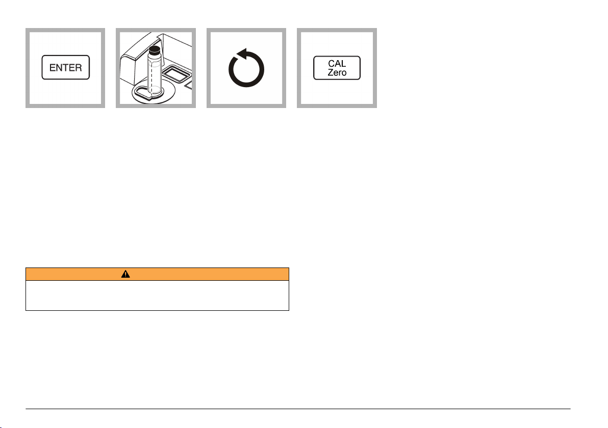
7. Push ENTER.
The instrument display
counts down from 60 to
0, and then measures
the standard.
The instrument shows
the next expected
standard (e.g., 20.00).
The mode display
shows "01".
8. Remove the sample
cell from the sample
cell holder.
9. Do steps 5–11 for
the other formazin
standards (from lowest
to highest NTU
standard). Mix each
formazin standard well
and rinse the sample
cell two times with
formazin standard
before the sample cell
is filled.
The mode display
shows "00" after the
last sample cell is
measured.
10. Push CAL/Zero.
The instrument saves
the new calibration data
and goes back to
Measurement mode.
Making 4000-NTU formazin stock solution
W A R N I N G
Chemical exposure hazard. Obey laboratory safety procedures and wear all of
the personal protective equipment appropriate to the chemicals that are handled.
Refer to the current material safety data sheets (MSDS) for safety protocols.
Note: Making formazin stock solution from raw materials is not recommended.
Preparation of formazin stock solution is temperature and technique sensitive. Use
Hach formazin stock solution to get the best instrument performance and analytical
standard accuracy.
1. Dissolve 5.000 grams of reagent grade hydrazine sulfate ((NH2)2–
H4H2SO4) in about 400 mL of demineralized water.
2. Dissolve 50.000 grams of reagent grade hexamethylenetetramine in
about 400 mL of demineralized water.
40 English
3. Quantitatively, put the two solutions in a 1-liter volumetric flask, and
dilute to volume with demineralized water. Mix fully.
4. Let the solution stand for 48 hours at 25 ± 1 °C (77 ± 1 °F).
Calibrate the turbidimeter with user-selected formazin standards
The instrument may be calibrated using user-selected values of formazin
standards.
Calibration with user-selected values of formazin standards is done
using the same method that is used to calibrate the instrument with
recommended formazin standards with two differences:

• The prepared formazin standards used are user-selected standards
and not the recommended standards. Refer to Prepare formazin
standards – user selected on page 41.
• The calibration points that are shown on the display must be changed
as they occur so they agree with the turbidity of the user-defined
standards. Refer to Change the calibration points on page 41.
Note: Unknown performance may occur if standards other than the recommended
calibration points are used. The recommended calibration points (< 0.1, 20, 200,
1000, 4000 and 7500 NTU) provide the best calibration accuracy. Refer to
Application note 128, Calibration Methods for Low-Level Turbidity Measurement.
Prepare formazin standards – user selected
User-selected values of formazin standards are prepared using the
same method that is used to prepare the recommended formazin
standards. Refer to Prepare formazin standards on page 37.
Prepare user-selected values of formazin standards to span the entire
range of the instrument. Four standards are necessary. Suggested
standards are in the range of:
• 10–30 NTU
• 180–220 NTU
• 900–1000 NTU
• 4000 NTU
Formazin standards greater than 80 NTU must have a difference of at
least 60 NTU.
Change the calibration points
When using user-selected values of formazin standards during
calibration, change the calibration points that are shown on the display
as they occur. Change the calibration points so that they agree with the
turbidity of the user-defined values.
For example: A 25-NTU standard is put in the sample cell holder
instead of the recommended 20-NTU standard during calibration.
Change the "20.000" on the display to "25.000" before pushing ENTER
to start the measurement.
To change the value on the display during calibration:
1. Push the right arrow key. The decimal point flashes.
2. Push the right arrow key to move the cursor to the next position.
3. Push ENTER to accept the new cursor position.
4. Use the up and down arrow keys to change the number on the
display.
5. Do steps 2–4 again if necessary to change the other digit.
6. Push ENTER to save the change and start the measurement.
Special research applications
The instrument has special features and operations for special research
applications.
Application specific methods
Use the application specific calibration (ASC) measurement modes to
measure turbidity with direct readout in units other than FNU, NTU or
EBC. The unit of measurement, initially referred to as ASC -1- and -2can be changed by choosing alpha numeric characters during method
entry.
The display value is set by entering a multiplication factor. The
instrument multiplies the actual NTU value by the multiplication factor
and shows the result.
For example: An application for monitoring in the Nephlos (NEP) unit of
measurement can be made by entering a multiplication factor of
6.7 (1 FNU or NTU is equivalent to 6.7 Nephlos).
Application specific calibration
This instrument can be used to enter an application specific unit and a
multiplication factor that gives results in that application specific unit. The
multiplication factor is applied to the NTU reading of the instrument and
shown in the application specific unit.
Either ASC multiplication factor can be changed at any time, so
recalibration is not necessary.
The sample is under-range if the display flashes 0s.
If the display flashes 0s when measuring Absorbance or transmittance,
set the analytical reference point again and measure again. Also, make
sure that the expected reading is positive when measuring absorbance.
English
41

Initial ASC entry
Note: Make sure that the instrument is calibrated before making NTU
measurements.
Program new ASC data
1. Push UNITS/Exit until the correct ASC unit name is shown on the
display (ASC -1- or -2-).
2. Push CAL/Zero to enter the ASC calibration mode.
The left digit flashes.
3. Use the arrow keys to enter a three-digit calibration name.
Note: The name cannot be one of the units already used FNU, NTU, EBC, %T,
A, -1- or -2-) .
4. Push ENTER.
ENTER MUL is shown on the display.
5. PushENTER.
The display shows "1.0000" (or the last factor entered) with the
decimal point flashing.
6. Push the right arrow key to move the decimal point to the right.
7. Push ENTER to accept the decimal point position.
The left digit of the display flashes.
8. Use the arrow keys to change the number on the display to the
correct multiplication factor for the data point.
9. Push ENTER to accept the multiplication factor.
The instrument returns to the measurement mode.
3. Use the arrow keys to select a measurement units option:
Option Description
U SET 0 Sets all the units as available on the display: FNU, FAU, NTU, -1-,
U SET 1 Set the units FNU and FAU as available on the display.
U SET 2 Sets the units FNU, FAU and NTU as available on the display.
U SET 3 Sets the units FNU, FAU and -1- (ASC) as available on the
-2-, EBC, %T, A
display.
4. Push ENTER.
5. Push SETUP.
Maintenance
D A N G E R
Multiple hazards. Only qualified personnel must conduct the tasks
described in this section of the document.
Clean the instrument
Keep the instrument clean to get continuous and accurate operation.
N O T I C E
Never use cleaning agents such as turpentine, acetone or similar products to
clean the instrument including the keypad.
Set the units available on the display
1. Push SETUP. The SETUP light turns on.
2. Select 85 using the arrow keys, then push ENTER.
"U SET 0" is shown on the display.
42
English
1. Turn the instrument off and disconnect the power cord.
2. Clean the surface of the instrument with a soft, moist cloth and a
weak soap solution.
3. Dry the surface of the instrument with a lint-free cloth.
Replace the LED light source
The light source, light emitting diode (LED), is not user replaceable.
Contact Customer Service for LED replacement.

Replace a fuse
D A N G E R
Fire hazard. Use the same type and current rating to replace fuses.
Replacement parts:
• Fuse for 115 V operation, time-delay, 250 V, 1.6 A (3030700), or
• Fuse for 230 V operation, time-delay, 250 V, 1.6 A (3030600)
To replace a fuse, refer to the illustrated steps in Figure 10.
Figure 10 Replace a fuse
Troubleshooting
Refer to the tables in this section for error codes, diagnostic codes,
common problem messages or symptoms, possible causes and
corrective actions.
Error codes
Table 7 lists the error codes shown for different conditions. Error codes
identify instrument malfunction or operator error.
The instrument continues operation in an error condition.
Push ENTER to clear an error code from the display.
Note: Any calibration being calculated when an error occurs, is discarded. The old
calibration is kept.
Table 7 Error codes
Error Description Solution
ERR01 The turbidity of the
dilution water is greater
than 0.5 NTU.
ERR02
• Two calibration
standards have the
same value.
• The difference
between two
calibration standards
is less than
60.0 NTU.
• The turbidity of
Standard 1 is too
low (less than
10 NTU).
Start the calibration again with lower turbidity
dilution water.
Note: Ignore ERR01 when the sample cell diameter
is less than 25 mm. Push UNITS/Exit to go back to
measurement mode.
1. Inspect the preparation of standards.
2. Do the calibration again.
Note: Ignore ERR02 when the sample cell diameter
is less than 25 mm. Push UNITS/Exit to go back to
measurement mode.
English 43

Table 7 Error codes (continued)
Error Description Solution
ERR03 Low light error
ERR04 Memory malfunction
ERR05 A/D is over the range
ERR06 A/D is under the range
ERR07 Light leak
ERR09 Printer time out error or
paper in the internal
printer can not move
ERR10 System voltage out of
range
1. Put the sample in the instrument again.
2. Make sure that the lamp icon light is on.
3. Make sure that an object is not in the
light path.
4. Do sample dilution if necessary.
1. Turn the instrument off and then back on.
2. Contact Technical Support if the error
occurs again.
1. Make sure that the light shield is closed.
2. Contact Customer Service if necessary.
1. Make sure that no object is in the light
path.
2. Contact Customer Service if necessary.
1. Make sure that the cover for the sample
cell compartment is closed.
2. Turn the instrument off and then back on.
1. Gently pull up on the paper in the internal
printer to remove the obstruction.
2. Make sure that the external printer is
connected correctly.
3. Make sure that the external printer is
selected (online).
1. Turn the instrument off and then back on.
2. Contact Customer Service if the error
occurs again.
Table 7 Error codes (continued)
Error Description Solution
ERR11 System loop test error
ERR12 ASC units name error Enter an application specific calibration
ERR14 Invalid time error The time must be between 00-00 and 23-59.
ERR15 Invalid date error The date must be between 01-00 and 12-31.
1. Turn the instrument off and then back on.
2. Contact Customer Service if the error
occurs again.
(ASC) unit name that is not one of the default
units (i.e., NTU or EBC).
Diagnostic codes
Table 8 lists the diagnostic codes that are used to get information about
instrument operation when instrument operation is in doubt.
To do a diagnostic test:
1. Push SETUP.
2. Use the arrow keys to enter a diagnostic code.
3. Push ENTER to show the diagnostic value.
4. Push UNITS/Exit to go back to Measurement mode.
Note: To print a diagnostic report, hold down PRINT, then turn the instrument on.
Table 8 Diagnostic codes
Code Display Description
21 "PRINT TST" Printer test
22 Test results are shown. Display test
23 Test results are shown. Keyboard test
24 Test results are shown. Memory test
44
English
Delete calibration data

To delete any calibration data entered by the user:
1. Turn off the instrument.
2. Push and hold CAL/Zero.
3. Turn on the instrument.
The CAL? light flashes. The instrument starts in Calibration mode.
4. Calibrate the instrument before use.
Flashing 9s
When manual ranging is selected, the display will flash all 9s when the
sample being measured is greater than the selected range.
When automatic ranging is selected, the display will flash 9s when the
sample is greater than the maximum range of the instrument. The
display will also flash 9s if Ratio is off and the measurement is greater
than 40 NTUs (1000 FNUs or 9.8 EBCs). Turn Ratio on. Refer to
Measure over-range samples on page 24.
Flashing 0s
When manual ranging is selected, the display will flash all 0s when the
sample measured is less than the selected range.
When automatic ranging is selected, the display will flash all 0s when the
measurement is less than the range of the instrument (i.e., less than
20 FAU) or a negative value. Calibrate the instrument.
• When measuring absorbance or transmittance, set the zero reference
point again.
• When measuring absorbance, make sure that the reading is positive.
To measure samples with negative absorbance, set the analytical
zero using the sample with the greatest absorbance and read the
sample with the least absorbance. Record the reading as negative
absorbance.
Replacement parts
Description Quantity Item no.
Calibration kit, StablCal®, sealed sample
cells (<0.1, 20, 200, 1000, 4000 and
7500 NTU)
Cover, sample cell compartment 1 4702500
Cover, printer 1 4705400
Dust cover 1 4703000
Fuse for 115 V operation, time-delay,
250 V, 1.6 A, UL/CSA approved
Fuse for 230 V operation, time-delay,
250 V, 1.6 A, IEC type, VDE approved
Gelex® secondary turbidity standardization
kit
(stray light standard and 0–2, 0–20, 0–200,
200-4000, and 4,000–10,000 NTU)
Oiling cloth 1 4707600
Power cord, North America, 115 VAC,
UL/CSA approved
Power cord, European, 230 VAC, VDE
approved
Printer paper, thermal 5 4709000
Sample cells, 30mL, 1 in. round glass 6 2084900
Silicone oil 1 126936
1 2659505
1 3030700
1 3030600
1 2589200
1 1801000
1 4683600
Replacement parts and accessories
Note: Product and Article numbers may vary for some selling regions. Contact the
appropriate distributor or refer to the company website for contact information.
English 45

Accessories
Description Quantity Item no.
Calibration kit, StablCal®, 100 mL each
(<0.1, 20, 200, 1000, 4000 and 7500 NTU)
Calibration kit, StablCal®, 500 mL each
(<0.1, 20, 200, 1000, 4000 and 7500 NTU)
Cable, computer, DB-9 to DB-9 1 4950200
Cell adapter, 12–13 mm 1 3033400
Cell adapter, 16 mm 1 3033500
Cell adapter, 19 mm 1 3033600
Filter disks 10 2323810
Filter, membrane (without pad) 200 1353001
Filter paper, glass fiber, quantitative,
47 mm
Flow cell kit, automated, 115 V, low
pressure
Flow cell kit, automated, 230 V, low
pressure
Flow cell kit, manual, low pressure 1 4744900
Flow cell, glass (included with the manual
and automated flow cell kit)
Flow valve module kit, 120 VAC, for the
automated flow cell
(includes the flow valve module and power
supply)
Flow valve module kit, 230 VAC, for the
automated flow cell
(includes the flow valve module and power
supply)
Formazin stock solution, 4000 NTU 100 mL 246142
1 2659510
1 2659500
100 253000
1 4745000
1 4745002
1 4709500
1 4744500
1 4744502
Replacement parts and accessories (continued)
Description Quantity Item no.
Formazin stock solution, 4000 NTU 500 mL 246149
Formazin high-range turbidity standard,
7500 NTU ampule
Pump, vacuum, hand-operated 1 1428300
Pump, vacuum/pressure, 115V, 60 Hz,
1.2 cfm
Pump, vacuum/pressure, 220V, 50 Hz,
1.2 cfm
Sample degassing kit 1 4397500
Sample degassing and filtration kit 1 4397510
0.1 NTU, StablCal™ low-level turbidity
verification standards (not for instrument
calibration)
0.3 NTU, StablCal™ low-level turbidity
verification standards (not for instrument
calibration)
0.5 NTU, StablCal™ low-level turbidity
verification standards (not for instrument
calibration)
TenSette® Pipet, 1.0-10.0 mL, 1 1970010
TenSette® Pipet Tips 250 2199725
Tubing, tygon, ¼-inch OD x 1/16 inch wide,
for the manual or automated flow cell
Tubing, tygon, 3/8-inch OD x 1/16 inch wide,
for the automated flow cell
Tubing, tygon, ½-inch OD x 1/16 inch wide,
for the manual flow cell
Ultrasonic bath 1 2489500
1 2584202
1 2424800
1 2824802
100 mL 2723342
100 mL 2697942
100 mL 2698042
1 ft 4134400
1 ft 518137
1 ft 518637
46 English

Replacement parts and accessories (continued)
Description Quantity Item no.
Volumetric flask, 100 mL, Class A 1 1457442
Volumetric flask, 200 mL, Class A 1 1457445
Optional reagents
Description Quantity Item no.
Hexamethylenetetramine 500 g 187834
Hydrazine sulfate 100 g 74226
English 47

48 English


HACH COMPANY World Headquarters
P.O. Box 389, Loveland, CO 80539-0389 U.S.A.
Tel. (970) 669-3050
(800) 227-4224 (U.S.A. only)
Fax (970) 669-2932
orders@hach.com
www.hach.com
©
Hach Company/Hach Lange GmbH, 2012. All rights reserved. Printed in Germany.
HACH LANGE GMBH
Willstätterstraße 11
D-40549 Düsseldorf, Germany
Tel. +49 (0) 2 11 52 88-320
Fax +49 (0) 2 11 52 88-210
info@hach-lange.de
www.hach-lange.de
HACH LANGE Sàrl
6, route de Compois
1222 Vésenaz
SWITZERLAND
Tel. +41 22 594 6400
Fax +41 22 594 6499
 Loading...