

Page 1

DOC023.52.03221.May07
1720E Low Range Turbidimeter
USER MANUAL
May 2007, Edition 7
Page 2

© HACH LANGE GmbH, 2007. All rights reserved. Printed in Germany.
Page 3

DOC023.52.03221.May07
1720E Low Range Turbidimeter
USER MANUAL
May 2007, Edition 7
© HACH LANGE GmbH, 2007. All rights reserved. Printed in Germany.
Page 4

Page 5

Table of Contents
Section 1 Specifications......................................................................................................................................... 3
Section 2 General Information ............................................................................................................................... 5
2.1 Safety Information............................................................................................................................................... 5
2.1.1 Use of Hazard Information......................................................................................................................... 5
2.1.2 Precautionary Labels................................................................................................................................. 5
2.1.3 General Product Information ..................................................................................................................... 6
2.2 Theory of Operation ............................................................................................................................................ 7
Section 3 Installation .............................................................................................................................................. 9
3.1 Connecting/Wiring the Sensor to the sc100 Controller ....................................................................................... 9
3.1.1 Attaching a sc Sensor with a Quick-connect Fitting .................................................................................. 9
3.1.2 Hard-wiring a sc Sensor to the sc100 Controller ..................................................................................... 10
3.2 Connecting the Sensor to the sc1000 Controller .............................................................................................. 11
3.2.1 Connecting the Sensor using the Quick-connect Fittings........................................................................ 11
3.3 Turbidimeter Installation Information................................................................................................................. 11
3.3.1 Mounting the Turbidimeter Body ............................................................................................................. 13
3.3.2 Installing the Head Assembly .................................................................................................................. 13
3.4 Installing a Sample Line.................................................................................................................................... 13
3.5 Sample Connections......................................................................................................................................... 14
Section 4 System Startup..................................................................................................................................... 15
4.1 General Operation ............................................................................................................................................ 15
4.2 Starting Sample Flow........................................................................................................................................ 15
Section 5 Operation .............................................................................................................................................. 17
5.1 Sensor Setup .................................................................................................................................................... 17
5.2 Sensor Data Logging ........................................................................................................................................ 17
5.3 Sensor Diagnostics Menu ................................................................................................................................. 17
5.4 Sensor Setup Menu .......................................................................................................................................... 18
5.5 Sensor Calibration and Verification................................................................................................................... 18
5.5.1 User-prepared Calibration ....................................................................................................................... 19
5.5.2 Calibration with StablCal
5.5.3 Instrument Verification............................................................................................................................. 21
5.5.3.1 Dry Verification............................................................................................................................... 21
5.5.3.2 Wet Verification .............................................................................................................................. 21
5.6 Calibration and Verification History ................................................................................................................... 22
5.7 Offset Feature ................................................................................................................................................... 22
5.7.1 Setting the Offset..................................................................................................................................... 23
Section 6 Maintenance ......................................................................................................................................... 25
6.1 Maintenance Schedule ..................................................................................................................................... 25
6.2 Removing a Sensor from the System ............................................................................................................... 25
6.3 Reinstalling a Sensor on the System ................................................................................................................ 25
6.4 Cleaning............................................................................................................................................................ 26
6.4.1 Cleaning the Photocell Window............................................................................................................... 26
6.4.2 Cleaning the Turbidimeter Body and Bubble Trap .................................................................................. 26
6.4.3 Replacing the Lamp Assembly ................................................................................................................ 27
® .......................................................................................................................................................20
Section 7 Troubleshooting................................................................................................................................... 29
7.1 Error Codes....................................................................................................................................................... 29
7.2 Warnings........................................................................................................................................................... 29
7.3 Event Codes ..................................................................................................................................................... 31
1
Page 6

Table of Contents
Section 8 Replacement Parts and Accessories..................................................................................................33
8.1 Replacement Items............................................................................................................................................33
8.2 Optional Accessories.........................................................................................................................................33
8.3 Calibration and Verification Standards and Accessories................................................................................... 34
Section 9 Contact ................................................................................................................................................. 35
Section 10 Warranty and liability ........................................................................................................................ 37
Section 11 Compliance Information .................................................................................................................... 39
Appendix A Modbus Register Information..........................................................................................................41
Index .......................................................................................................................................................................43
2
Page 7
Section 1 Specifications
Specifications are subject to change without notice.
Table 1 1720E Low Range Specifications
Range 0–100 nephelometric turbidity units (NTU)
Measurement Units mg/L, NTU, TE/F, FTU, Degree
± 2% of reading or ± 0.02 NTU (whichever is greater) from 0 to 40 NTU;
± 5% of reading from 40 to 100 NTU (when calibration is performed at 20.0 NTU with the
offset turned off).
Better than 1% 0–40 NTU on formazin. Allows for accurate calibration at high turbidity values.
Accuracy
Linearity
1
1
Resolution (Displayed)
Repeatability Better than ±1.0% of reading or ±0.002 NTU, whichever is greater
Response Time
Sample Flow Required 250 to 750 mL/minute
Storage Temperature –20 to 60 °C (–4 to 140 °F)
Operating Temperature 0 to 50 °C (32–122 °F) for single sensor system, 0 to 40 °C (32–104 °F) for two sensor system
Sample Temperature
Range
Operating Humidity 5 to 95% non-condensing
0.0001 NTU up to 9.9999 NTU; 0.001 NTU from 10.000 to 99.999 NTU; 0.01 NTU at 100.00
NTU
For a full-scale step change, initial response in 1 minute, 15 seconds. Varies with flow rate,
see the table below. The response time is also dependent on the signal averaging time, which
is user selectable.
Flow Rate
% Step Change
750 500 250
10 1¼ minutes 1½ minutes 2½ minutes
50 2 minutes 2½ minutes 6 minutes
90 3½ minutes 3½ minutes 9 minutes
99 4 minutes 5 minutes 12 minutes
0 to 70 °C
Power Requirements 12 VDC ± 5%, 12.5 Watts maximum
1
Sample Inlet Fitting
Signal Average Time no averaging, 6, 30, 60, and 90 seconds, user selectable. Default is 30 seconds.
Dimensions Turbidimeter body and cap: 25.4 x 30.5 x 40.6 cm (10 x 12 x 16 inches)
Sensor Cable Length 2 m (6.6 ft); Optional 7.62 m (25 ft)
Mounting Options Turbidimeter Body and Head Assembly: Wall; floor stand
Shipping Weight
Calibration Methods
/8 barb fitting to ¼-inch NPT male adapter
1720E Series 2 Turbidimeter and Controller: 6.31 kg (13.5 lb); 1720E Turbidimeter only: 4.71
kg (10 lb)
1. StablCal
Recommended at 20.0 NTU.
2. Formazin – user-prepared primary or wet calibration of the instrument. Recommended at
20.0 NTU.
3. Multi-sensor calibration – Performed with a specialized calibration procedure for up to
eight sensors on a single set of fresh StablCal
®
(stabilized formazin) – primary or wet calibration of the instrument.
®
standards.
3
Page 8
Specifications
Table 1 1720E Low Range Specifications (continued)
1. StablCal
Verification (Wet) Method
2. Formazin – fresh user-prepared standard
1. ICE-PIC™ Verification Module with factory-set values of 20.0 or 1.0 ±25%. Unique value
Verification (Dry) Method
Recommended
Maintenance
Installation Environment Indoor
1. Lamp replacement: once per year.
2. Cleaning: mandatory before calibration, optional before calibration, and mandatory upon
®
(stabilized formazin) – recommended for verification in the appropriate
application range of measurement. For regulatory verification, standards of 0.1 to 50
NTU.
is assigned when dry verification is done immediately after calibration and is used as
pass/fail criteria for subsequent verifications.
verification failure.
Primary Compliance
Method
Limit of Detection
1
All specifications are based on a calibration with 20.0 NTU formazin and with the offset turned off.
1
USEPA 180.1; Hach Method 8195; ASTM D 6698; Standard Methods 2130B
0.0032 NTU (according to criteria specified by ISO 15839)
4
Page 9
Section 2 General Information
2.1 Safety Information
Please read this entire manual before unpacking, setting up, or operating this equipment.
Pay attention to all danger and caution statements. Failure to do so could result in serious
injury to the operator or damage to the equipment.
To ensure that the protection provided by this equipment is not impaired, do not use or
install this equipment in any manner other than that specified in this manual.
2.1.1 Use of Hazard Information
DANGER
Indicates a potentially or imminently hazardous situation which, if not avoided,
could result in death or serious injury.
CAUTION
Indicates a potentially hazardous situation that may result in minor or moderate
injury.
Important Note: Information the requires special emphasis.
Note: Information that supplements points in the main text.
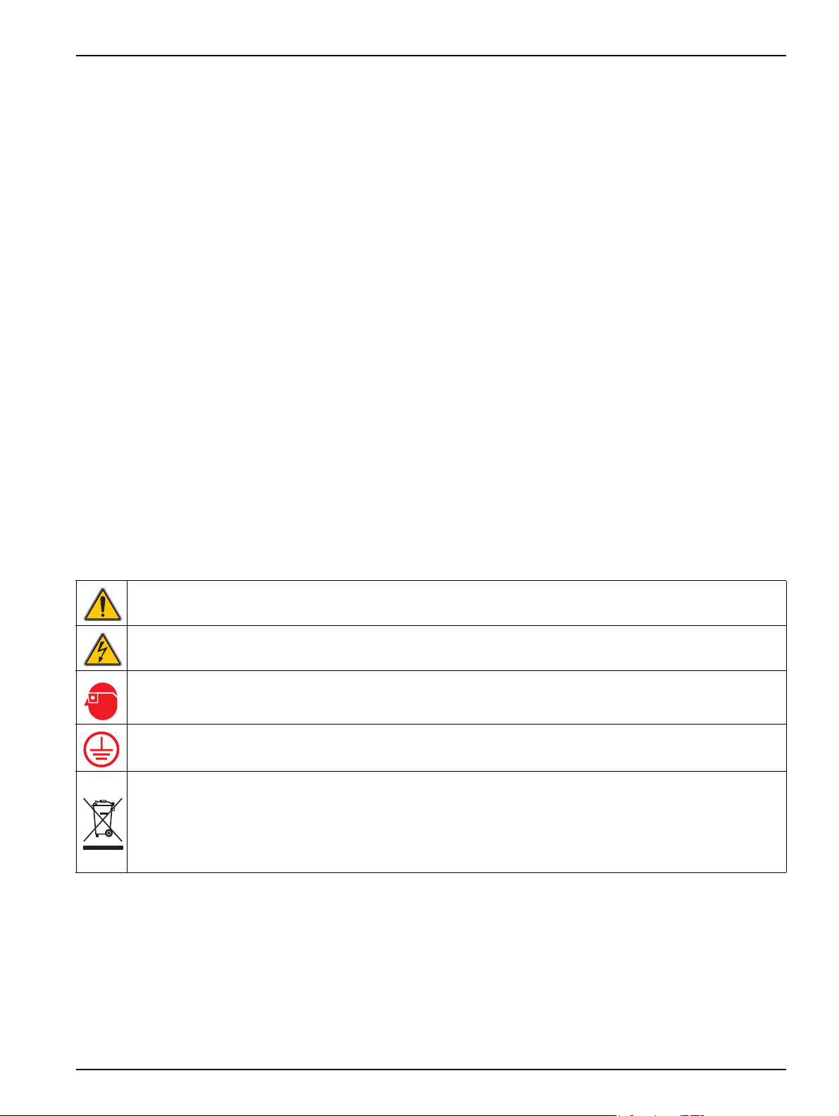
2.1.2 Precautionary Labels
Read all labels and tags attached to the instrument. Personal injury or damage to the
instrument could occur if not observed.
This symbol, if noted on the instrument, references the instruction manual for operation and/or safety information.
This symbol, when noted on a product enclosure or barrier, indicates that a risk of electrical shock and/or
electrocution exists.
This symbol, if noted on the product, indicates the need for protective eye wear.
This symbol, when noted on the product, identifies the location of the connection for Protective Earth (ground).
Electrical equipment marked with this symbol may not be disposed of in European public disposal systems after
12 August of 2005. In conformity with European local and national regulations (EU Directive 2002/96/EC), European
electrical equipment users must now return old or end-of life equipment to the Producer for disposal at no charge to
the user.
Note: For return for recycling, please contact the equipment producer or supplier for instructions on how to return
end-of-life equipment, producer-supplied electrical accessories, and all auxiliary items for proper disposal.
5
Page 10

General Information
2.1.3 General Product Information
The 1720E Turbidimeter is a continuous-reading nephelometric turbidimeter designed for
low-range turbidity monitoring. This process turbidimeter is capable of measuring turbidity
from 0.001 to 100.0 NTU. Calibration is based on formazin, the primary turbidity reference
standard adopted by the APHA Standard Methods for the Examination of Water and
Wastewater and the U.S. Environmental Protection Agency (EPA) and on StablCal
is also recognized as a primary standard.
The 1720E Turbidimeter can be operated using an sc controller. Refer to the Operation
section (Section 5 on page 17) for more information.
®
which
6
Page 11
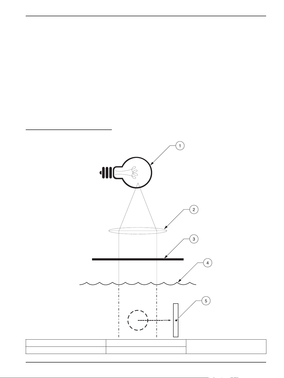
2.2 Theory of Operation
The 1720E Turbidimeter measures turbidity by directing a strong beam of collimated light
from the sensor head assembly down into the sample in the turbidimeter body. Light
scattered at 90° relative to the center line of incident light by suspended particles in the
sample is detected by the submerged photocell (Figure 1).
The amount of light scattered is proportional to the turbidity of the sample. If the turbidity of
the sample is negligible, little light will be scattered and detected by the photocell and the
turbidity reading will be low. High turbidity, on the other hand, will cause a high level of
light scattering and result in a high reading.
Sample enters the turbidimeter body and flows through the baffle network of the bubble
trap. The flow allows bubbles to either cling to surfaces of the baffle system or rise to the
surface and vent to atmosphere. After traveling through the bubble trap, sample enters the
center column of the turbidimeter body, rises into the measuring chamber and spills over
the weir into the drain port. A reading is taken once per second.
Figure 1 90 Degree Detector
General Information
1. Lamp 3. Aperture 5. 90° Detector
2. Lens 4. Water Level
7
Page 12

General Information
8
Page 13
Section 3 Installation
DANGER
Only qualified personnel should conduct the tasks described in this section of the
manual. The 1720E/sc100 product configuration is not intended for installation in
hazardous locations.
3.1 Connecting/Wiring the Sensor to the sc100 Controller
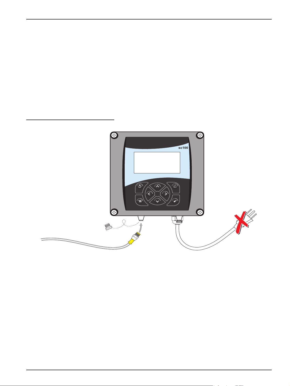
3.1.1 Attaching a sc Sensor with a Quick-connect Fitting
The sensor cable is supplied with a keyed quick-connect fitting for easy attachment to the
controller, see Figure 2. Retain the connector cap to seal the connector opening in case
the sensor must be removed. The 1720E sensor cable may be extended by a maximum of
7.62 m (25 ft), see Replacement Parts and Accessories on page 33.
Figure 2 Attaching the Sensor using the Quick-connect Fitting
9
Page 14
Installation
3.1.2 Hard-wiring a sc Sensor to the sc100 Controller
1. Disconnect power to the controller if powered.
2. Open the controller cover.
3. Disconnect and remove the existing wires between the quick-connect and terminal
strip J5, see Figure 3.
4. Remove the quick-connect fitting and wires and install the threaded plug on the
opening to maintain the environmental rating.
5. Cut the connector from the sensor cable.
6. Strip the insulation on the cable back 1-inch. Strip ¼-inch of each individual wire end.
7. Pass the cable through conduit and a conduit hub or a strain relief fitting
(Cat. No. 16664) and an available access hole in the controller enclosure.
Tighten the fitting.
Note: Use of strain relief fitting other than Cat. No. 16664 may result in a hazard. Use only the
recommended strain relief fitting.
8. Reinstall the plug on the sensor access opening to maintain the environmental rating.
9. Wire as shown in Table 2 and Figure 3.
10. Close and secure the cover.
Table 2 Wiring the Sensor at Terminal Block J5
Terminal Number Terminal Designation Wire Color
1 Data (+) Blue
2 Data (–) White
3 Service Request No Connection
4 +12 V dc Brown
5 Circuit Common Black
6 Shield Shield (grey wire in existing quick disconnect fitting)
10
Page 15
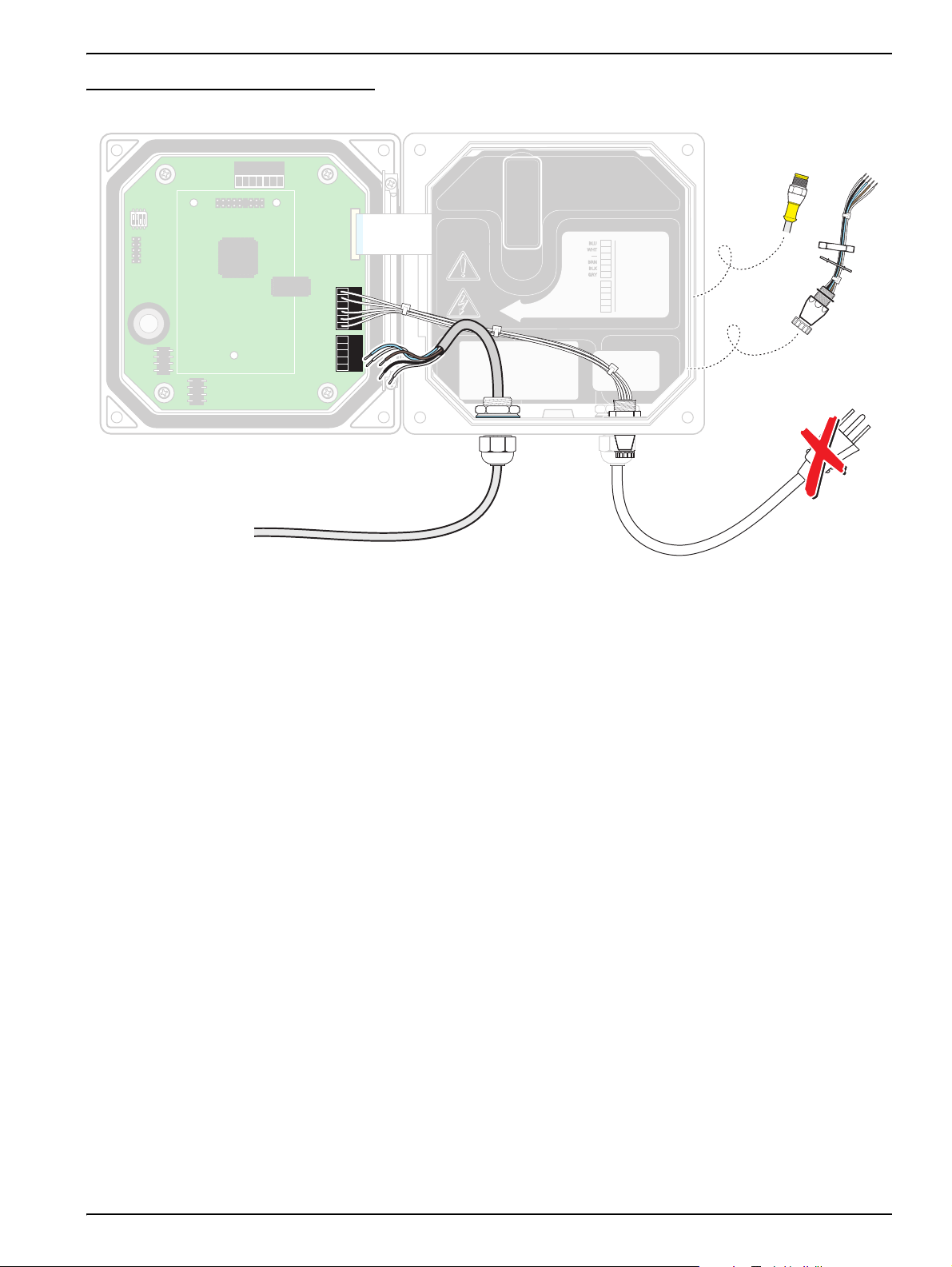
Figure 3 Hard-wiring the Sensor
1
1
+
DATA
+
OUT 2
– DATA
– OUT 2
SERVICE REQUEST
SHIELD/CHASSIS GND
+
V
+
OUT 1
GND
– OUT 1
2
2
3
3
4
4
5
5
6
PROBES
ANALOG OUTPUTS
PCB
CONNECTOR
FIELD WIRING
INSULATION MUST
BE RATED TO
80° C MINIMUM
NCNCNC
COMCOMCOM
NO
F1
F2
NONO
RELAY3RELAY2RELAY1
1
1
+
DATA
+
OUT 2
– DATA
– OUT 2
SERVICE REQUEST
SHIELD/CHASSIS GND
+
V
+
OUT 1
GND
– OUT 1
2
2
3
3
4
4
5
5
6
PROBES
ANALOG OUTPUTS
PCB
CONNECTOR
FIELD WIRING
INSULATION MUST
BE RATED TO
80° C MINIMUM
1
1
+
DATA+DATA
+
OUT 2+OUT 2
– DATA
– OUT 2
SERVICE REQUEST
SHIELD/CHASSIS GND
+V+
V
+
OUT 1+OUT 1
GND
– OUT 1
2
2
3
3
4
4
5
5
6
PROBES
ANALOG OUTPUTS
PCB
CONNECTOR
PCB
CONNECTOR
FIELD WIRING
INSULATION MUST
BE RATED TO
80° C MINIMUM
FIELD WIRING
INSULATION MUST
BE RATED TO
80° C MINIMUM
DANGER - EXPLOSION HAZARD
DANGER - RISQUE D'EXPLOSION
DO NOT DISCONNECT WHILE CIRCUIT IS LIVE
UNLESS AREA IS KNOWN TO BE NON-HAZARDOUS.
NE PAS DEBRANCHER TANT QUE LE EST SOUS
TENSION, A MONIS QU'IL NE S'AGISSE D'UN
EMPLACEMENT NON-DANGEROUX
NCNCNC
COMCOMCOM
NO
F1
F2
NONO
RELAY3RELAY2RELAY1
1
1
+
DATA+DATA
+
OUT 2+OUT 2
– DATA
– OUT 2
SERVICE REQUEST
SHIELD/CHASSIS GND
+V+
V
+
OUT 1+OUT 1
GND
– OUT 1
2
2
3
3
4
4
5
5
6
PROBES
ANALOG OUTPUTS
PCB
CONNECTOR
PCB
CONNECTOR
FIELD WIRING
INSULATION MUST
BE RATED TO
80° C MINIMUM
FIELD WIRING
INSULATION MUST
BE RATED TO
80° C MINIMUM
J1
J2
J4
NETWORK
INTERFACE
CARD
J3
U5
U9
S1
DANGER - EXPLOSION HAZARD
DANGER - RISQUE D'EXPLOSION
DO NOT DISCONNECT WHILE CIRCUIT IS LIVE
UNLESS AREA IS KNOWN TO BE NON-HAZARDOUS.
NE PAS DEBRANCHER TANT QUE LE EST SOUS
TENSION, A MONIS QU'IL NE S'AGISSE D'UN
EMPLACEMENT NON-DANGEROUX
J1
S1
J2
U5
J4
U9
NETWORK
INTERFACE
CARD
J3
J5J5
J5
J5
J6
PCB
PCB
CONNECTOR
CONNECTOR
DANGER - EXPLOSION HAZARD
DANGER - EXPLOSION HAZARD
DO NOT DISCONNECT WHILE CIRCUIT IS LIVE
DO NOT DISCONNECT WHILE CIRCUIT IS LIVE
UNLESS AREA IS KNOWN TO BE NON-HAZARDOUS.
UNLESS AREA IS KNOWN TO BE NON-HAZARDOUS.
DANGER - RISQUE D'EXPLOSION
DANGER - RISQUE D'EXPLOSION
NE PAS DEBRANCHER TANT QUE LE EST SOUS
NE PAS DEBRANCHER TANT QUE LE EST SOUS
TENSION, A MONIS QU'IL NE S'AGISSE D'UN
TENSION, A MONIS QU'IL NE S'AGISSE D'UN
EMPLACEMENT NON-DANGEROUX
EMPLACEMENT NON-DANGEROUX
+
DATA
+
DATA
+
V
+
V
+
OUT 2
+
OUT 2
+
OUT 1
+
OUT 1
FIELD WIRING
FIELD WIRING
INSULATION MUST
INSULATION MUST
BE RATED TO
BE RATED TO
80° C MINIMUM
80° C MINIMUM
Installation
Disconnect
Power
From Probe
3.2 Connecting the Sensor to the sc1000 Controller
3.2.1 Connecting the Sensor using the Quick-connect Fittings
1. Unscrew the connector cap from the controller. Retain the connector cap to seal the
connector opening in case the sensor must be removed.
2. Push the connector into the socket.
3. Hand-tighten the union nut.
Note: Do not use the middle connection for the sensors as this is reserved for the display module.
3.3 Turbidimeter Installation Information
The turbidimeter body is designed for wall-mounting (although it may be mounted on the
optional floor stand). The turbidimeter sensor must be mounted within six feet of the
controller unless an extension cable is used. Maximum cable length is 9.6 m (31 feet).
11
Page 16

Installation
Figure 4 1720E Dimensions
12
Page 17

3.3.1 Mounting the Turbidimeter Body
Locate the turbidimeter as close to the sampling point as possible. A shorter distance for
the sample to travel results in a faster response time.
Clean the turbidimeter body and bubble trap before installation using the instructions
supplied in section 6.4.2 on page 26. Slotted mounting brackets are integral parts of the
turbidimeter body. Install customer-supplied hardware appropriate for the installation
environment using the criteria detailed below:
• Install in a location that is isolated from vibration.
• Allow at least 22 cm (approximately 10 inches) clearance for removal of the head
assembly and bubble trap cover from the top of the turbidimeter body.
• Leave enough room below the turbidimeter body to remove the bottom plug and to
place a container under the drain when calibrating or cleaning.
Note: Make sure the top of the turbidimeter body is level.
• Install two ¼-20 bolts 10-3/4 inches apart (on center). Leave at least ¼-inch of the bolt
head exposed.
• Make sure the bolts are installed level.
Installation
Slide the slotted mounting brackets of the turbidimeter body onto the bolts.
3.3.2 Installing the Head Assembly
After the turbidimeter body has been mounted, install the bubble trap cover, then place the
head assembly on the turbidimeter body with the label facing the front. Move the head
assembly back and forth slightly to ensure it is properly seated on the body of the
instrument. Failure to properly seat the head will result in light leakage and
erroneous readings.
The rear portion of the head assembly has a molded “lip” which may be used to hang the
head assembly on the turbidimeter body edge for routine maintenance.
3.4 Installing a Sample Line
DANGER
This turbidimeter is not designed for use in hazardous locations or with samples
that are flammable or explosive in nature. If any sample solution other than water is
used in this product, test the sample/product compatibility to ensure user safety
and proper product performance.
One-fourth inch OD rigid or semi-rigid tubing is recommended for sample lines. Run them
as directly as possible between the turbidimeter body and the sampling point to minimize
sample flow lag time.
Install sample line taps into larger process pipes to minimize interference from air bubbles
or pipeline bottom sediment. A tap projecting into the center of the pipe is ideal. Figure 5
shows examples of sample tap installations.
Note: When setting the flow rate, take care to avoid sweeping air “micro-bubbles” through the
internal bubble trap. Observe the sample flow inside the turbidimeter body. If small air bubbles can
be seen flowing up through the center, reduce the flow rate.
13
Page 18

Installation
Figure 5 Sampling Techniques
1
3
2
4
5 6 7 8
1. Sample Flow 4. Sediment (Typical) 7. Good
2. Sampling Line to Sensor 5. Poor 8. Best
3. Air (Typical) 6. Poor
3.5 Sample Connections
Sample inlet and drain connections are made on the turbidimeter body. The sample inlet
fitting installed in the body is a ¼-inch NPT
fitting supplied with the instrument is a ½-inch NPT-to-hose fitting for use with ½-inch ID
flexible plastic tubing on the drain.
x ¼-inch compression fitting. One additional
Note: For samples with high solids content (high turbidity), operate at the highest flow rate possible.
For samples with low solids content (low expected turbidity), operate at a low flow rate
(200–300 mL/min).
The required flow rate is 200 to 750 mL/min (4.0 to 11.9 gal/hour). Flow rate into the
turbidimeter may be controlled with a flow restriction device on the inlet line. Flow rates
below 200 mL/min will reduce response time and cause inaccurate readings. Flow rates
above 750 mL/min will cause the turbidimeter to overflow, indicating flow rate is too high.
Figure 6 Sample Connections
STATUS
POWER
1
2
3
1. Sample Inlet, ¼-28 NPT x ¼-inch Compression fitting 2. Drain, ½-inch NPT fitting 3. Service Drain
14
Page 19

Section 4 System Startup
4.1 General Operation
Plug the sensor into the unpowered controller by aligning the orientation tab on the cable
connector with the channel in the controller connector. Push in and turn to secure the
connection. Tug gently to check the connection.
After all plumbing and electrical connections have been completed and checked, place the
head on the body and supply power to the system. Ensure the head is seated on the body
when power is applied, since dark readings are measured at this time. If power is applied
while the sensor head is off the turbidimeter body, cycle the power with the sensor head on
the body.
The first time a controller is powered up, a language selection menu will appear. The user
must select the correct language from the displayed options.
Following language selection and upon power-up, the controller will search for connected
sensors. The display will show the main measurement screen.
4.2 Starting Sample Flow
Start sample flow through the instrument by opening the sample supply valve. Allow the
turbidimeter to run long enough for the tubing and body to become completely wetted and
the reading on the display to stabilize. One to two hours or longer may be required initially
for complete stabilization. Allow measurements to become stable through adequate
conditioning before completing instrument settings or performing calibrations.
15
Page 20

System Startup
16
Page 21

Section 5 Operation
5.1 Sensor Setup
When a sensor is initially installed, the serial number of the sensor will be displayed as the
sensor name. To change the sensor name refer to the following instructions:
1. Select Main Menu.
2. From the Main Menu, select SENSOR SETUP and confirm.
3. Highlight the appropriate sensor if more than one sensor is attached and confirm.
4. Select CONFIGURE and confirm.
5. Select EDIT NAME and edit the name. Confirm or cancel to return to the Sensor
Setup menu.
5.2 Sensor Data Logging
The sc100 provides two data logs (one for each sensor) and two event logs (one for each
sensor). The data logs store the measurement data at selected intervals. The event log
stores a variety of events that occur on the devices such as configuration changes,
alarms, and warning conditions. The data logs are stored in a packed binary format and
the event logs are stored in a CSV format. The logs can be downloaded through the digital
network port, service port, or the IrDA port. DataCom is needed for downloading logs to a
computer. If the datalogging frequency is set to 15 minute intervals, the instrument can
continue to store data for approximately six months.
1. From the Main Menu, select SENSOR SETUP and confirm.
2. Select CONFIGURE and confirm.
3. Select the datalog interval (30 seconds, 1 minute, 5 minutes, 10 minutes or
15 minutes). Confirm.
5.3 Sensor Diagnostics Menu
SELECT SENSOR
ERROR LIST See section 7.1 on page 29.
WARNING LIST See section 7.2 on page 29.
17
Page 22

Operation
5.4 Sensor Setup Menu
SELECT SENSOR (if more than one sensor is attached)
CALIBRATE
USER PREPD CAL Calibration using 4000 NTU stock solution diluted to 20.00 NTU formazin.
STABLCAL CAL Calibration using 20 NTU StablCal Stabilized Formazin Standard
VERIFICATION Perform a verification, set the pass/fail criteria, and view the verification history.
0 ELECTRONICS Zero electronics
CAL HISTORY
CONFIGURE
BUBBLE REJECT Choose Yes or No to enable/disable bubble reject. Default: Yes
SIGNAL AVG
MEAS UNITS
EDIT NAME
SET RESOLUTION Set the number of significant digits to display. Default is three significant digits.
DATALOG INTRVL
OFFSET Enter an offset between –0.05 to 0.05 NTU. Values outside this range are not accepted.
View the last 12 entered calibrations. Confirm to move to the next history entry. See section 5.6
on page 22 for more information.
Choose no averaging or specify the amount of time for signal averaging. Available options are:
no averaging, 6 sec., 30 sec., 60 sec., or 90 sec. Default is 30 seconds.
Select the appropriate measurement units to display. Choose from mg/L, NTU, TE/F, FTU and
Degree. Default: NTU
Enter up to a 12-digit name in any combination of symbols and alpha or numeric characters.
Confirm when the entry is complete. The name will be displayed on the status line above the
measurement value on the main display.
Choose the amount of time between saving data points to the data log. Default: 15 min.;
Options: 30 sec., 1 minute, 5 minutes, 10 minutes, or 15 minutes.
DIAG/TEST
SOFTWARE VERS. Displays the software version number.
SERIAL NUMBER Displays the serial number of the sensor.
INT TEMP Displays the internal temperature of the sensor electronics in °C.
DEFAULT SETUP Restores the sensor’s factory default settings and invalidates the current calibration.
POWER CHECK Displays the electrical statistics for the sensor.
SERVICE MODE Choose On or Off to enable/disable service mode. Default: Off
SERVICE DIAGS Passcode protected. Menu options only available to service personnel.
5.5 Sensor Calibration and Verification
The manufacturer offers two EPA-approved calibration methods one using user-prepared
formazin and the other using StablCal
(wet and dry) are also offered.
The 1720E Turbidimeter is factory-calibrated using StablCal
shipment. The instrument must be recalibrated before use to meet published
accuracy specifications. In addition, recalibration is recommended after any significant
maintenance or repair and at least once every three months during normal operation. The
turbidimeter body and bubble trap must be thoroughly cleaned and rinsed before
initial use and prior to each calibration.
®
Stabilized Formazin. Two verification methods
Stabilized Formazin before
18
Tips to achieve the most accurate calibrations:
• Optimum performance is achieved when calibration is performed in the turbidimeter
body. Accurately prepare the standard then add it to the turbidimeter body at the
appropriate step in the procedure. Do not prepare the standard in the body.
Page 23

Operation
• Stop sample flow, drain, and clean the turbidimeter body before beginning the
calibration procedure.
• Always clean the photocell window per the instructions in section 6.4.1 on page 26.
Rinse the photocell with deionized water and dry with a soft, lint-free cloth before
calibrating.
• Always clean the turbidimeter body or calibration cylinder per the instructions in
section 6.4.2 on page 26. Rinse with deionized water before calibrating.
• Store the calibration cylinder upside-down to minimize contamination between
calibrations.
• Pour the calibration standard into the turbidimeter body at the inflow end (left side
when facing the instrument).
• Gently invert StablCal standards for 1 minute before opening. Do not shake. This
ensures a consistent turbidity of the standard.
• If the 20.0 NTU StablCal standard is allowed to sit in the calibration cylinder or
turbidimeter body for more than 15 minutes, it must be remixed (gently swirled in the
calibration cylinder) before use to ensure a consistent turbidity.
• Discard all standards after use per the instructions on the container. Never transfer the
standard back into its original container. Contamination will result.
• Always recalibrate after restoring default settings.
5.5.1 User-prepared Calibration
The user-prepared calibration is a two-step calibration in which the difference between the
DI water and the standard value is used to determine the gain of the instrument. The water
used for the standard solution must be from the same source as that which the DI water
measurement is made. Variation in dilution of the water source could negatively impact the
accuracy of the calibration. The manufacturer does not recommend calibrating below
1.0 NTU, and instrument specifications are based on the calibration point at 20 NTU.
Before starting the calibration, read and apply the tips in section 5.5 on page 18.
Follow the procedure as written (using 1 L of deionized water and 5.0 mL of 4000 NTU
formazin) if using a calibration cylinder for calibration.
If using the turbidimeter body for the user-prepared calibration follow the procedure
below using 20.0 NTU formazin in step 12. Follow the steps below for proper
calibration:
1. Stop the sample flow, then drain and clean the body.
2. Prepare a 20.0 NTU standard by adding 5.0 mL of 4000 NTU formazin to a 1-L flask.
Dilute to the mark with deionized water and invert gently to mix.
3. Drain the deionized water and pour the prepared 20.0 NTU standard into the
turbidimeter body at step 12. Do not add additional 4000 NTU formazin.
4. From the Main Menu, select SENSOR SETUP and confirm.
5. Select the appropriate sensor if more than one is connected and confirm.
6. Select CALIBRATE and confirm.
7. Select USER PREPD CAL and confirm.
8. Select the available Output Mode (Active, Hold, or Transfer) from the list and confirm.
19
Page 24

Operation
9. Stop the sample flow. Drain and clean the body and bubble trap. Fill the cylinder with
1 L deionized water. Replace the head and confirm.
Important Note: Carefully pour the DI water in such a way that minimizes any bubble
formation that would result in a false, high reading.
10. The measured reading (based on a gain of 1.0) is displayed. Confirm.
11. Enter the standard turbidity value of the user prepared standard and confirm.
12. Drain the cylinder. Pour the prepared standard into the cylinder and confirm.
13. The measured reading (based on a gain of 1.0) is displayed. Confirm.
14. The display will read GOOD CAL! GAIN: X.XX ENTER TO CONT. Confirm. (If the
calibration was unsuccessful, the display will read BAD CAL! Confirm to redo or exit.)
15. The display will read VERIFY CAL? Confirm to verify or exit without verification.
Note: If a dry verification is performed directly after a calibration, the measured value is assigned as
the expected value for future verifications (when using the dry verification device with the same
serial number). As long as the verification exists within the verification history, the expected value will
be retained. Otherwise, the expected value will be the nominal labeled value associated with the dry
verification device.
16. Select the verification type (begin at step 5 in section 5.5.3.1 on page 21 for dry
verification or section 5.5.3.2 on page 21 for wet verification) or enter initials to
complete calibration.
17. Return the sensor to measure mode and confirm.
5.5.2 Calibration with StablCal
Before starting the calibration, read and apply the tips in section 5.5 on page 18.
1. From the Main Menu, select SENSOR SETUP and confirm.
2. Select the appropriate sensor if more than one is connected and confirm.
3. Select CALIBRATE and confirm.
4. Select STABLCAL CAL and confirm. Select the available Output Mode (Active, Hold,
or Transfer) from the list and confirm.
5. Enter the standard turbidity value of the user prepared standard and confirm.
6. Drain/clean/rinse the turbidimeter body or cal cylinder. Pour the 20 NTU standard into
the cylinder body. Replace the head and confirm.
7. The measured reading (based on a gain of 1.0) is displayed. Confirm.
®
20
8. The display will read GOOD CAL! GAIN: X.XX ENTER TO CONT. Confirm. (If the
calibration was unsuccessful, the display will read BAD CAL! Confirm to redo or exit.)
9. The display will read VERIFY CAL? Confirm to verify or exit without verification.
Note: If a dry verification is performed directly after a calibration, the measured value is assigned as
the expected value for future verifications (when using the dry verification device with the same
Page 25

serial number). As long as the verification exists within the verification history, the expected value will
be retained. Otherwise, the expected value will be the nominal value associated with the dry
verification device.
10. Select the VERIFICATION type (begin at step 5 in section 5.5.3.1 on page 21 for dry
verification or section 5.5.3.2 on page 21 for wet verification) or enter initials to
complete calibration.
11. Return the sensor to measure mode and confirm.
5.5.3 Instrument Verification
Instrument verification is intended as a simple check to ensure Turbidimeter functionality
between calibrations. Two types of verifications are offered. The dry verification is
performed using a “dry” calibration device such as the ICEPIC™. A wet verification is
performed using a standard with a predetermined value such as StablCal
Formazin.
A dry verification directly after calibration is used to establish the baseline. Any verification
afterwards, until the next calibration, that uses the same dry verification standard will
reference the recorded value from the baseline verification as the “expected” value. In
order for the verification to pass, the measured value should be within the limits set by the
Pass/Fail Criteria of the baseline value.
Operation
®
Stabilized
5.5.3.1 Dry Verification
1. From the Main Menu, select SENSOR SETUP and confirm.
2. Select CALIBRATE and confirm.
3. Select VERIFICATION and confirm.
4. Select PERFORM VER and confirm. Select the available Output Mode (Active, Hold,
5. Select DRY for the verification type and confirm.
6. Select 1 NTU STD or 20 NTU STD or verify SN of previously used calibration device
7. Set the Head to Standard and confirm. Confirm again to accept the reading.
8. The display will read GOOD VER!. Confirm.
9. Enter initials and confirm.
10. Return the sensor to measure mode and confirm.
or Transfer) from the list box and confirm.
and confirm.
5.5.3.2 Wet Verification
Before starting the verification, read and apply the appropriate tips in section 5.6. For wet
verification values at or below 1.0 NTU, only use the cleaned turbidimeter body.
1. From the Main Menu, select SENSOR SETUP and confirm.
2. Select CALIBRATE and confirm.
3. Select VERIFICATION and confirm.
21
Page 26

Operation
4. Select PERFORM TEST and confirm. Select the available Output Mode (Active, Hold,
or Transfer) from the list box and confirm.
5. Select WET for the verification type and confirm.
6. Enter the Std Turbidity and confirm.
7. Drain and clean the sensor body and confirm.
8. Pour the standard into cylinder. Replace the head and confirm.
9. The reading will be displayed. Confirm to accept the verification.
10. Return the sensor to measure mode and confirm.
5.6 Calibration and Verification History
The calibration and verification history logs contain information on the last 12 calibrations
and the last 12 verifications. The calibration history log shows the gain value, the time and
date of the calibration, and the initials of the operator performing verification.
Note: Restoring default settings from the DIAG/TEST menu will return the turbidimeter to its non
calibration state (gain = 1.0) but it will not remove the previous calibration history from memory.
The calibration history log is accessed from the Calibrate menu. The verification history
log is accessed from the Verification menu (a submenu of the Calibrate menu).
Each verification history entry shows the serial number of the verification device (dry
verification) or the value of the verification standard (wet verification), the time and date of
the verification, and the initials of the operator performing the verification.
Scroll through the entries by pressing the
histories, the display will return to the calibration menu level.
When the instrument is received from the factory, default values or blank spaces will be
shown for the calibration and verification history information. Those values will be replaced
with real data as the history log is filled.
The data is retained as first in, first out. When the log is full, the newest entry is stored and
the oldest entry in the log is deleted.
5.7 Offset Feature
The offset or clean water offset (CWO) feature will allow a ± 0.05 NTU offset to the
measured value. The offset value denoted as CWO will be subtracted from the value
displayed on the sc Interface. The 0.05 NTU offset can be entered after a calibration is
complete and is based on an independent determination of the water used in the
preparation of the turbidity standards.
ENTER key. After scrolling through all 12
22
Note: The offset is a limited value. An offset outside the range of ± 0.05 mg/L, ± 0.05 NTU,
± 0.05 TE/F, ± 0.05 FTU or ± 0.05 Degree will not be accepted.
For example, if a standard is prepared with a value of 0.8 NTU, the 0.05 NTU offset would
result in a displayed value of 0.75 NTU. See the Setting the Offset section to change the
offset value. When the offset is used, the letters CWO are displayed after the turbidity
value in the upper-right corner.
Page 27

5.7.1 Setting the Offset
Follow the steps below to enter an offset:
Note: The data log for this channel will be erased if the offset is changed to anything other than zero.
1. From the Main Menu select SENSOR SETUP and confirm.
2. Select 1720E and confirm.
3. Select CONFIGURE and confirm.
Note: Offset is not used during calibration. During calibration the offset is zero.
4. Move the pointer to OFFSET and confirm.
5. The display will show an Offset screen. Use the arrow keys to enter the offset. The
value entered must be between –0.05 to 0.05 NTU, values outside this range are
not accepted.
6. Confirm to accept the offset reading.
Operation
23
Page 28

Operation
24
Page 29

Section 6 Maintenance
DANGER
Only qualified personnel should conduct the tasks described in this section of the
manual.
6.1 Maintenance Schedule
Maintenance Task Frequency
Clean the sensor
Calibrate Sensor (as required by regulatory
agency)
Scheduled periodic maintenance requirements of the 1720E are minimal and include
calibration and cleaning of the photocell window, bubble trap, and body. Check and clean
the bubble trap and turbidimeter body (as described in section 6.4.2) if visual inspection
shows that it is necessary. Perform other maintenance on a regular basis; experience will
dictate scheduling and may depend on the installation, sample type, and season.
It is very important to maintain the cleanliness of the interior and exterior of the
turbidimeter body, head assembly, the integral bubble trap, and the surrounding area.
Doing so will ensure accurate, low-level turbidity measurements.
Clean the turbidimeter body before performing any calibration or wet verification
(especially when measurements are being made at 1.0 NTU or lower).
Check and/or perform a calibration periodically (as experience dictates) using one of the
methods described in section 5.5 on page 18. A calibration history menu option is
available under Sensor Setup/Calibrate.
Before each calibration and as needed. Depends on sample
characteristics.
Per agency-dictated schedule.
6.2 Removing a Sensor from the System
Prior to physically removing a sensor from the system, record all user defined settings
such as relays, signal averaging, etc. Disconnect the sensor connector at the controller.
6.3 Reinstalling a Sensor on the System
To return the system to normal operation following a software upgrade or sensor repair
perform the following procedure:
1. Detach all sensors from the sc100 controller.
2. From the main menu, press the down arrow key to highlight TEST/MAINT.
Press ENTER.
3. Use the down arrow key to scroll to SCAN SENSORS and press ENTER.
4. Remove attached sensors by selecting the corresponding serial number or select “All”.
5. Power down the sc100 then attach the 1720E.
Note: Clean sensors before reinstallation on the system.
6. Supply power to the sc100. The system will initialize automatically.
25
Page 30

Maintenance
6.4 Cleaning
6.4.1 Cleaning the Photocell Window
Occasional cleaning of the photocell window is required. The frequency will depend on the
nature and concentration of dissolved and suspended solids in the sample. Biological
activity is a primary factor in mineral scale deposit on the window and the amount differs
with sample temperature. In general, more growth will occur in warm temperatures and
less in cold.
Note: Do not disassemble the photocell assembly. It contains liquid.
Note: Take care to not scratch the photocell window.
Inspect the photocell window often to determine cleaning needs. Remove any organic
growth or film on the photocell window before standardization or calibration. Use a cotton
swab and isopropyl alcohol or a mild detergent (such as Liqui-nox
sediment and dirt. Mineral scale buildup may require cleaning with a mild acid applied with
a cotton swab followed by a detergent wash. Do not use abrasive cleaners.
6.4.2 Cleaning the Turbidimeter Body and Bubble Trap
®
) to remove most
Sediment may collect in the turbidimeter body after extended use. Noise (fluctuation) in
the reading could indicate the need to clean the body and/or bubble trap. The 1720E
bubble trap and bottom plate may be removed to make cleaning easier. Drain and clean
the turbidimeter body before each calibration. Establish a regular schedule or perform
cleaning as determined by visual inspection.
Cleaning the Turbidimeter Body
Note: The turbidimeter body, bubble trap, and detector must be cleaned before each calibration.
1. Turn off sample flow to the turbidimeter body.
2. Remove the head assembly and bubble trap cover from the body. Remove the bubble
trap by lifting it vertically. Set it aside to be cleaned separately.
3. Drain the body by removing the plug from the bottom of the body.
4. Replace the drain plug and fill the body to the weir with cleaning solution. This
cleaning solution can consist of dilute chlorine solution (25 mL of household bleach in
3.78 liters of water) or a laboratory detergent such as Liqui-nox (1 mL detergent in
1 liter of water).
5. Use a soft brush to clean the inside surfaces of the body.
6. Remove the drain plug again and thoroughly flush the turbidimeter body with
ultra-filtered deionized water. Clean and replace the plug.
26
Cleaning the Bubble Trap
1. Prepare a cleaning solution (as in step 4 above) in a container large enough to
submerge the entire bubble trap.
2. Using a test tube brush such as Cat. No. 690-00, clean each surface.
3. Rinse the bubble trap thoroughly with ultra-filtered deionized water and reinstall it in
the turbidimeter body.
Page 31

Maintenance
4. Replace the bubble trap cover and head assembly on the top of the body.
5. Restore sample flow to the instrument.
6. Calibrate the instrument using one of the methods in section 5.5 on page 18.
If the above cleaning procedures have been performed and the turbidimeter readings are
still noisy, the bottom plate and gasket may need to be removed and cleaned. Carefully
perform the following procedure to ensure the turbidimeter body integrity is maintained.
1. Turn off sample flow to the turbidimeter body.
2. Remove the head assembly, bubble trap cover, and bubble trap (by lifting it vertically)
from the body.
3. Drain the body by removing the plug from the bottom of the body.
4. Lift the body off of its mounting screws.
5. With the body turned upside-down, remove the two Phillips-head screws holding the
bottom plate.
6. Lift the bottom plate off the body; set the gasket aside for use in reassembly.
7. Use a soft brush and a dilute cleaning solution (as prepared above) to clean the
bottom plate and inside surfaces of the turbidimeter body. Rinse the entire body and
bottom plate with ultra-filtered deionized water.
8. Reassemble by inserting the gasket into the molded channel in the bottom plate.
9. Fit the bottom plate onto the turbidimeter body.
10. Reinstall both screws and carefully tighten to 15 inch-lb maximum.
11. Reinstall the turbidimeter onto the wall mounting screws.
12. Replace the bubble trap, bubble trap cover, and head assembly on the top of the body.
13. Restore sample flow to the instrument.
6.4.3 Replacing the Lamp Assembly
The Lamp Assembly is located on the head assembly. Under normal use, Hach
recommends replacing the lamp once a year to maintain peak performance. Replacement
bulbs have been “burned-in” at the factory and are ready for installation and use.
To change the lamp, refer to Figure 7 on page 28 and perform the following steps:
1. Disconnect power to the controller to remove all power to the turbidimeter.
2. Disconnect the lamp leads by unplugging the connector.
27
Page 32

Maintenance
3. After the bulb has cooled, remove as follows:
a. Wear cotton gloves to protect your hands and to avoid fingerprints on the bulb.
b. Grasp the bulb.
c. Twist the bulb in a counterclockwise direction, pulling out slightly, until it is
released from the housing.
d. Pull the lamp leads and connector through the hole in the lamp housing.
Do not touch the new bulb with bare hands. Etched glass and reduced lamp life will result.
Wear cotton gloves or grasp the lamp assembly with a tissue to avoid contamination. If
contamination occurs, clean the glass bulb portion with isopropyl alcohol.
Replace the bulb by reversing the above instructions. The bulb base only fits one way;
align the notch in the metal bulb flange with the hole in the lamp holder.
Figure 7 Lamp Replacement
1
1. Lamp Housing 2. Lamp Assembly 3. Photo Detector
2
3
28
Page 33

Section 7 Troubleshooting
7.1 Error Codes
When a sensor is experiencing an error condition, the sensor reading on the
measurement screen will flash and all relays and analog outputs associated with the
sensor will be held.
7.2 Warnings
Highlight the Probe Diag menu and press
ENTER. Highlight Errors and press ENTER to
determine the case of the error. Errors are defined in Table 3.
Table 3 Error Codes
Displayed Error Definition
A/D Fail Failed A/D converter. Call the Service Department.
Lamp Fail
Flash Fail Datalog and event log will not work.
The light source has failed. See section 6.4.3 on page 27 for instructions for
replacing it.
A sensor warning will leave all menus, relays, and outputs functioning normally, but will
cause a warning icon to flash on the right side of the display. Highlight the Probe Diag
menu and press
ENTER to determine the cause of the error. Warnings are defined in
Table 4.
A warning may be used to trigger a relay and users with the sc100 controller can set
warning levels to define the severity of the warning (see the sc100 controller user manual
for more information about warning levels). Errors are defined in Table 4.
Table 4 Warning Codes
Warning
Number
1 Dark Reading Warning Dark reading detects too much light. (> 0.05 NTU)
2 Temp Warning
3 Data Log Full
4 Event Log Full
5 5 Volt Warn Monitored voltage is outside the range of 4.5–5.5 V.
6 Inp V Warn Monitored voltage is outside the range of 9.08–14.13 V.
7 Lamp Volt Warn Monitored voltage is outside the range of 3.96–4.48 V.
8 Lamp Curr Warn Monitored current is outside the range of 1.67–2.75 Amps.
9 Output Mode Warn
Displayed Warning Definition/Resolution
Sensor head internal temperature is higher than specified. Contact the Service
Department. (> 70 °C)
Sensor data log is full. No additional data will be logged until sensor log is
downloaded into controller memory.
Sensor data log is full. No additional data will be logged until sensor log is
downloaded into controller memory.
Activated when the sensor is not in normal measurement mode (such as when
in calibration or verification mode).
29
Page 34

Troubleshooting
Table 5 presents sensor warnings displayed in the Event Log, possible causes, and
corrective actions.
Table 5 General Troubleshooting
Sensor Warning Possible Cause Corrective Action
Lamp burned out Replace the lamp. See section 6.4.3 on page 27.
Lamp unplugged Restore connection
Bad Lamp
Low Signal
Bad System Voltage
A/D Converter Timeout
High Dark Counts
+12 V connection loose at controller Restore connection
Dislodged lamp Reinstall lamp
Bad circuit board in turbidimeter head Contact the Customer Service Department.
Photocell coated/dirty
Photocell wires disconnected Reconnect wires
Photocell broken/cracked
Lens coated/dirty Clean the lens using isopropyl alcohol and a cotton swab.
Obstructed light path Remove obstruction
See Bad Lamp causes above See Bad Lamp corrective actions above
Improper wiring at controller Refer to section 3.1 on page 9.
Turbidimeter head cable shortened to
improper length
Fluctuation in voltage Turn instrument power off and back on.
Bad circuit board in turbidimeter head Contact the Service Department
Fluctuation in voltage Turn instrument power off and back on.
Bad circuit board in turbidimeter head Contact the Customer Service Department.
Light Leak—Turbidimeter head not on
turbidimeter body or calibration
cylinder during Power Up or Zero
Electronics
Light Leak—Turbidimeter head not
properly aligned on the turbidimeter
body or calibration cylinder during
Power Up or
Zero Electronics
Photocell broken/cracked Contact the Customer Service Department.
See section 6.4.1 on page 26.
Contact the Customer Service Department.
Replace photocell
Contact the Customer Service Department.
Contact the Customer Service Department.
Make sure the turbidimeter head is on the turbidimeter
body and properly aligned and repower instrument or
perform ZERO ELECTRONICS in the CALIBRATION
MENU.
Make sure the turbidimeter head is properly aligned and
repower instrument or perform ZERO ELECTRONICS in
the CALIBRATION MENU.
Table 6 presents additional malfunctions which may not be recorded in the Event Log.
Table 6 Additional Malfunctions Not Recorded in the Event Log
Symptom Possible Cause Corrective Action
Continuous Underrange The calibration standard was either
improperly prepared or was unstable at
the time the calibration was accepted.
Continuous Overrange
(100 NTU)
Erratic Readings Inadequate bubble removal from sample Verify the accuracy of calibration standards and
The calibration standard was either
improperly prepared or was unstable at
the time the calibration was accepted.
Verify the accuracy of calibration standards and
recalibrate the instrument. See Low Signal in Table 5.
Verify the accuracy of calibration standards and
recalibrate the instrument.
recalibrate the instrument.
Increase the signal averaging time to a longer interval.
Make sure the Bubble Reject feature is turned on.
Slow the flow of sample into the instrument.
30
Page 35

Troubleshooting
Table 6 Additional Malfunctions Not Recorded in the Event Log (continued)
Symptom Possible Cause Corrective Action
High Readings Deionized water turbidity is greater than
0.5 NTU
Clean the instrument.
Access Calibration History for turbidity value of
ultra-filtered water.
Verify the flow is between 200–750 mL/min.
Recalibrate the instrument.
7.3 Event Codes
Event codes are not displayed on controller and must be downloaded from the event log to
be viewed. Troubleshooting actions are provided in Table 5 on page 30.
Table 7 Event Log List
Event Event # Data1 Data2 Data3
Bubble Reject Change 0
Filter Size Change 1
Data Log Interval Change 2
Power On 3 1 — —
Calibration 4 Cal Gain Initials —
Verification 5 Expected Value Meas Value Initials
Dark Reading Warning 6 Measured Value — —
Temperature Warning 7 Temperature Value — —
Voltage Warning 8
Lamp Warning 9
A/D Fail 10 1 — —
Lamp Fail 11 2 — —
Flash Fail 12 4 — —
Output Mode Change 13
0 = OFF
1= ON
0 = No avg, 1 = 6 sec
2 = 30 sec, 3 = 60 sec
4 = 90 sec
0 = 30 sec, 1 = 1min
2 = 5 min, 3 = 10 min
4 = 15 min
16 = +5V high
32 = +5V low
64 = V in high
128 = V in low
1 = lamp V high
2 = lamp V low
4 = lamp I high
8 = lamp I low
0 = Active, 1 = Hold
2 = Transfer, 4 = Normal
——
——
——
——
——
——
31
Page 36

Troubleshooting
32
Page 37

Section 8 Replacement Parts and Accessories
8.1 Replacement Items
Description QTY Catalog Number
Lamp Assembly each 18950-00
Instruction Manual, 1720E Turbidimeter System, English each 60100-18
8.2 Optional Accessories
Description QTY Catalog Number
Cable, sensor extension, 7.7 m (25 ft) each 57960-00
Cap, Connector Receptacle each 52100-00
Deionized (demineralized) water 1 L 272-56
Drain plug for the 1720E body each 44116-00
Filter, 0.45 µm, to produce ultra-filtered water for cleaning and calibration each 26705-00
Filter, 0.2 µm, to produce ultra-filtered water for calibration standard preparation each 23238-10
Formazin Calibration Kit includes: Calibration Cylinder, TenSette® Pipet, 4000 NTU
Formazin Primary Standard (500 mL)
Floor Stand each 57432-00
Flow meter, 500–700 mL/min each 40282-00
ICE-PIC Module for Calibration and Calibration Verification, 20 NTU each 52250-00
ICE-PIC Module for Calibration and Calibration Verification, 1 NTU each 52215-00
Lid, Bubble Trap, 1720E each 52012-00
LonWorks Card each 59200-02
Photocell Replacement Kit for the 1720E each 52180-00
Pipet tips for 19700-01 TenSette Pipet 50/pkg 21856-96
Pipet tips for 19700-10 TenSette Pipet 50/pkg 21997-96
StablCal Calibration Set for the 1720 Series Turbidimeter
Includes: StablCal Standards, < 0.1 NTU, 20.0 NTU 1 L/each 26596-00
StablCal Standard, 0.1 NTU 1 L 27233-53
StablCal Standard, 0.3 NTU 1 L 26979-53
StablCal Standard, 0.5 NTU 1 L 26980-53
StablCal Standard, 1.0 NTU 1 L 26598-53
Strain relief, Heyco each 16664
Swabs, Cotton, presterilized for cleaning the photodetector 100/pkg 25543-00
TenSette Pipet, 0.1 to 1.0 mL each 19700-01
TenSette Pipet, 1.0 to 10.0 mL each 19700-10
Tubing, Inlet, ¼-inch OD, Polyethylene per foot 51322-00
Tubing, Outlet, ½-inch ID, ¾ inch OD, Tygon R3603 per foot 51263-00
each 44156-00
33
Page 38

Replacement Parts and Accessories
8.3 Calibration and Verification Standards and Accessories
Description QTY Catalog Number
Calibration Cylinder each 44153-00
Formazin Calibration Standards, Formazin, 4000 NTU Stock Solution 500 mL 2461-49
Calibration/Verification Modules
ICE-PIC™ Module, 1 NTU 1 each 52215-00
ICE-PIC™ Module, 20 NTU 1 each 52250-00
®
StablCal
Calibration Standards
StablCal® Stabilized Formazin Standard, 1 NTU 1 L 26598-53
®
StablCal
StablCal® Stabilized Formazin Standard, <0.1 NTU 1 L 26597-53
StablCal
<0.1 NTU
StablCal® Stabilized Formazin Standard, 40 NTU 1 gallon (3.78 L) 27463-56
StablCal
Stabilized Formazin Standard, 20 NTU 1 L 26601-53
®
Stabilized Formazin Set, four 1-L bottles 20-NTU and four 1-L bottles
®
Stabilized Formazin Standard, 0.1 NTU 1 gallon (3.78 L) 27233-56
1 L each 26596-00
34
Page 39

Section 9 Contact
HACH LANGE GMBH
Willstätterstraße 11
D-40549 Düsseldorf
Tel. +49 (0)2 11 52 88-0
Fax +49 (0)2 11 52 88-143
info@hach-lange.de
www.hach-lange.com
DR. BRUNO LANGE GES. MBH
Industriestraße 12
A-3200 Obergrafendorf
Tel. +43 (0)27 47 74 12
Fax +43 (0)27 47 42 18
info@hach-lange.at
www.hach-lange.at
HACH LANGE SA
Motstraat 54
B-2800 Mechelen
Tél. +32 (0)15 42 35 00
Fax +32 (0)15 41 61 20
info@hach-lange.be
www.hach-lange.be
HACH LANGE LTD
Pacific Way
Salford
GB-Manchester, M50 1DL
Tel. +44 (0)161 872 14 87
Fax +44 (0)161 848 73 24
info@hach-lange.co.uk
www.hach-lange.co.uk
DR. BRUNO LANGE AG
Juchstrasse 1
CH-8604 Hegnau
Tel. +41(0)44 9 45 66 10
Fax +41(0)44 9 45 66 76
info@hach-lange.ch
www.hach-lange.ch
DR. LANGE NEDERLAND B.V.
Laan van Westroijen 2a
NL-4003 AZ Tiel
Tel. +31(0)344 63 11 30
Fax +31(0)344 63 11 50
info@hach-lange.nl
www.hach-lange.nl
HACH LANGE LTD
Unit 1, Chestnut Road
Western Industrial Estate
IRL-Dublin 12
Tel. +353(0)1 46 02 5 22
Fax +353(0)1 4 50 93 37
info@hach-lange.ie
www.hach-lange.ie
HACH LANGE FRANCE S.A.S.
33, Rue du Ballon
F-93165 Noisy Le Grand
Tél. +33 (0)1 48 15 68 70
Fax +33 (0)1 48 15 80 00
info@hach-lange.fr
www.hach-lange.fr
HACH LANGE APS
Åkandevej 21
DK-2700 Brønshøj
Tel. +45 36 77 29 11
Fax +45 36 77 49 11
info@hach-lange.dk
www.hach-lange.dk
HACH LANGE AB
Vinthundsvägen 159A
SE-128 62 Sköndal
Tel. +46 (0)8 7 98 05 00
Fax +46 (0)8 7 98 05 30
info@hach-lange.se
www.hach-lange.se
HACH LANGE LDA
Av. do Forte nº8
Fracção M
P-2790-072 Carnaxide
Tel. +351 214 253 420
Fax +351 214 253 429
info@hach-lange.pt
www.hach-lange.pt
HACH LANGE S.R.O.
Roľnícka 21
SK-831 07 Bratislava – Vajnory
Tel. +421 (0)2 4820 9091
Fax +421 (0)2 4820 9093
info@hach-lange.sk
www.hach-lange.sk
HACH LANGE S.R.L.
Via Riccione, 14
I-20156 Milano
Tel. +39 02 39 23 14-1
Fax +39 02 39 23 14-39
info@hach-lange.it
www.hach-lange.it
HACH LANGE SP.ZO.O.
ul. Opolska 143 a
PL-52-013 Wrocław
Tel. +48 (0)71 342 10-83
Fax +48 (0)71 342 10-79
info@hach-lange.pl
www.hach-lange.pl
HACH LANGE KFT.
Hegyalja u. 7-13.
H-1016 Budapest
Tel. +36 (06)1 225 7783
Fax +36 (06)1 225 7784
info@hach-lange.hu
www.hach-lange.hu
HACH LANGE S.L.U.
Edif. Arteaga Centrum
C/Larrauri, 1C- 2ª Pl.
E-48160 Derio/Vizcaya
Tel. +34 94 657 33 88
Fax +34 94 657 33 97
info@hach-lange.es
www.hach-lange.es
HACH LANGE S.R.O.
Lešanská 2a/1176
CZ-141 00 Praha 4
Tel. +420 272 12 45 45
Fax +420 272 12 45 46
info@hach-lange.cz
www.hach-lange.cz
HACH LANGE S.R.L.
str. Aviator Teodor Iliescu nr.37,
Sector 1
RO-011672, Bucuresti
Tel. +40 (0)21 2 08 95 78
Fax +40 (0)21 2 08 95 78
info@hach-lange.ro
www.hach-lange.ro
35
Page 40

Contact
HACH LANGE
8, Kr. Sarafov str.
BG-1164 Sofia
Tel. +359 (0)2 963 44 54
Fax +359 (0)2 866 04 47
info@hach-lange.bg
www.hach-lange.bg
ΗΑCH LANGE E.Π.Ε.
Αυλίδος 27
GR-115 27 Αθήνα
Τηλ . +30 210 7777038
Fax +30 210 7777976
info@hach-lange.gr
www.hach-lange.gr
HACH LANGE SU
ANALİZ SİSTEMLERİ LTD. ŞTİ.
Hilal Mah. 75. Sokak
Arman Plaza No: 9/A
TR-06550 Çankaya/ANKARA
Tel. +90 (0)312 440 98 98
Fax +90 (0)312 442 11 01
bilgi@hach-lange.com.tr
www.hach-lange.com.tr
HACH LANGE E.P.E.
27, Avlidos str
GR-115 27 Athens
Tel. +30 210 7777038
Fax +30 210 7777976
info@hach-lange.gr
www.hach-lange.gr
HACH LANGE D.O.O.
Fajfarjeva 15
SI-1230 Domžale
Tel. +386 (0)59 051 000
Fax +386 (0)59 051 010
info@hach-lange.si
www.hach-lange.si
36
Page 41

Section 10 Warranty and liability
The manufacturer warrants that the product supplied is free of
material and manufacturing defects and undertakes the obligation
to repair or replace any defective parts at zero cost.
The warranty period for instruments is 24 months. If a service
contract is taken out within 6 months of purchase, the warranty
period is extended to 60 months.
With the exclusion of the further claims, the supplier is liable for
defects including the lack of assured properties as follows: all those
parts that, within the warranty period calculated from the day of the
transfer of risk, can be demonstrated to have become unusable or
that can only be used with significant limitations due to a situation
present prior to the transfer of risk, in particular due to incorrect
design, poor materials or inadequate finish will be improved or
replaced, at the supplier's discretion. The identification of such
defects must be notified to the supplier in writing without delay,
however at the latest 7 days after the identification of the fault. If the
customer fails to notify the supplier, the product is considered
approved despite the defect. Further liability for any direct or
indirect damages is not accepted.
If instrument-specific maintenance and servicing work defined by
the supplier is to be performed within the warranty period by the
customer (maintenance) or by the supplier (servicing) and these
requirements are not met, claims for damages due to the failure to
comply with the requirements are rendered void.
Any further claims, in particular claims for consequential damages
cannot be made.
Consumables and damage caused by improper handling, poor
installation or incorrect use are excluded from this clause.
The manufacturer process instruments are of proven reliability in
many applications and are therefore often used in automatic control
loops to provide the most economical possible operation of the
related process.
To avoid or limit consequential damage, it is therefore
recommended to design the control loop such that a malfunction in
an instrument results in an automatic change over to the backup
control system; this is the safest operating state for the environment
and the process.
37
Page 42

Warranty and liability
38
Page 43

Section 11 Compliance Information
Hach Co. certifies this instrument was tested thoroughly, inspected and found to meet its
published specifications when it was shipped from the factory.
The Model sc100/sc1000 with 1720E Sensor has been tested and is certified as
indicated to the following instrumentation standards:
Product Safety
UL 61010A-1 (ETL Listing # 65454)
CSA C22.2 No. 1010.1 (ETLc Certification # 65454)
Certified by Hach Co. to EN 61010-1 Amds. 1 & 2 (IEC1010-1) per 73/23/EEC,
supporting test records by Intertek Testing Services.
Immunity
This equipment was tested for Industrial level EMC per:
EN 61326 (EMC Requirements for Electrical Equipment for Measurement, Control and
Laboratory Use)
certified compliance by Hach Company.
per 89/336/EEC EMC: Supporting test records by Hach Company,
Emissions
Standards include:
IEC 1000-4-2:1995 (EN 61000-4-2:1995) Electro-Static Discharge Immunity (Criteria
B)
IEC 1000-4-3:1995 (EN 61000-4-3:1996) Radiated RF Electro-Magnetic Field
Immunity (Criteria A)
IEC 1000-4-4:1995 (EN 61000-4-4:1995) Electrical Fast Transients/Burst (Criteria B)
IEC 1000-4-5:1995 (EN 61000-4-5:1995) Surge (Criteria B)
IEC 1000-4-6:1996 (EN 61000-4-6:1996) Conducted Disturbances Induced by RF
Fields (Criteria A)
IEC 1000-4-11:1994 (EN 61000-4-11:1994) Voltage Dip/Short Interruptions (Criteria
B)
Additional immunity Standard/s include:
ENV 50204:1996 Radiated Electro-Magnetic Field from Digital Telephones (Criteria A)
This equipment was tested for Radio Frequency Emissions as follows:
Per 89/336/EEC EMC: EN 61326:1998 (Electrical Equipment for measurement, control
and laboratory use—EMC requirements) Class “A” emission limits. Supporting test
records by Hewlett Packard, Fort Collins, Colorado Hardware Test Center (A2LA #
0905-01) and certified compliance by Hach Company.
Standards include:
EN 61000-3-2 Harmonic Disturbances Caused by Electrical Equipment
EN 61000-3-3 Voltage Fluctuation (Flicker) Disturbances Caused by
Electrical Equipment
Additional Emissions Standard/s include:
EN 55011 (CISPR 11) Class “A” emission limits
39
Page 44

Compliance Information
Canadian Interference-causing Equipment Regulation, IECS-003, Class A
Supporting test records by Hewlett Packard, Fort Collins, Colorado Hardware Test Center
(A2LA # 0905-01) and certified compliance by Hach Company.
This Class A digital apparatus meets all requirements of the Canadian InterferenceCausing Equipment Regulations.
Cet appareil numÈrique de la classe A respecte toutes les exigences du RËglement sur le
matÈriel brouilleur du Canada.
FCC PART 15, Class “A” Limits
Supporting test records by Hewlett Packard, Fort Collins, Colorado Hardware Test Center
(A2LA # 0905-01) and certified compliance by Hach Company.
This device complies with Part 15 of the FCC Rules. Operation is subject to the following
two conditions:
(1) this device may not cause harmful interference, and (2) this device must accept any
interference received, including interference that may cause undesired operation.
Changes or modifications to this unit not expressly approved by the party responsible for
compliance could void the user's authority to operate the equipment.
This equipment has been tested and found to comply with the limits for a Class A digital
device, pursuant to Part 15 of the FCC Rules. These limits are designed to provide
reasonable protection against harmful interference when the equipment is operated in a
commercial environment. This equipment generates, uses, and can radiate radio
frequency energy and, if not installed and used in accordance with the instruction manual,
may cause harmful interference to radio communications. Operation of this equipment in a
residential area is likely to cause harmful interference, in which case the user will be
required to correct the interference at his own expense. The following techniques of
reducing the interference problems are applied easily.
1. Disconnect the Controller from its power source to verify that it is or is not the source
of the interference.
2. If the Controller is connected into the same outlet as the device with which it is
interfering, try another outlet.
3. Move the Controller and 1720E sensor away from the device receiving the
interference.
4. Reposition the device receiving the interference.
5. Try combinations of the above.
40
Page 45

Appendix A Modbus Register Information
Table 8 Sensor Modbus Registers
Group Name Tag Name
Measurements Cal Gain 40013 float 2 R none 0.5 to 2.0
Verification PF Criteria 40062 Integer 1 R/W % 5 to 10
Measurements Turbidity 40001 Float 2 R NTU 0/100
Diagnostics Temperature 40005 Float 2 R Deg C —
Diagnostics Dark Reading 40009 Float 2 R NTU 0/100
Diagnostics Raw Turbidity 40011 Float 2 R NTU 0/100
Diagnostics Lamp Voltage 40018 Float 2 R Volts 0/5
Diagnostics Lamp Current 40020 Float 2 R Amps 0/2.75
Diagnostics Plus 5V 40022 Float 2 R Volts 0/5.5
Diagnostics Voltage In 40024 Float 2 R Volts 0/1443
Setup Software Version 40015 Float 2 R — —
Setup Bubble Rej 40017 Integer 1 R/W — On/Off
Setup DataLog Interval 40026 Integer 1 R/W Sec or Min
Setup Sensor Name 40027 String 6 R/W — —
Setup Filter Size 40033 Integer 1 R/W sec
Setup Sensor Ser Num 40036 String 6 R — 12 digits
Setup Output Mode 40042 Integer 1 R — 0, 1, 2, 4
Register #Data
Type
Length R/W Units (U) Range
30 sec, 1 min,
5min, 10 min,
15 min
no averaging,
6, 30, 60, 90
Setup Set Resolution 40061 Integer 1 R/W decimal places 4, 3, or 2
41
Page 46

Modbus Register Information
42
Page 47

Index
Numerics
90 Degree Detector ................................................... 7
A
Accuracy .................................................................... 3
B
Bubble trap ................................................................ 7
C
Calibration ................................................................ 18
History
StablCal
User-prepared
Calibration Methods
Cleaning
............................................................... 22
............................................................. 20
................................................... 19
................................................... 3
................................................................... 26
E
Event Codes ............................................................ 31
F
Flow Rate ................................................................. 14
H
Head Assembly ........................................................ 13
M
Maintenance
Cleaning
Schedule
Mounting
............................................................ 26
........................................................... 25
.................................................................. 13
P
Photocell Window .................................................... 26
Power Requirements
................................................. 3
R
Range ........................................................................ 3
Response Time
.......................................................... 3
S
Safety Information ...................................................... 5
Sample
Connections
Flow
................................................................... 15
Sample Line Installation
Sensor Cable
Connecting
Wiring
Starting Sample Flow
System Power
System Startup
...................................................... 14
........................................... 13
.......................................................... 9
.................................................................. 9
............................................... 15
.......................................................... 15
........................................................ 15
T
Theory of Operation ................................................... 7
Turbidimeter Body
.................................................... 26
V
Verification ............................................................... 18
W
Warnings
Sensor
............................................................... 30
43
Page 48

Index
44
 Loading...