

Page 1

DOC024.98.93051
ORBISPHERE Model
3100 Portable Analyzer
07/2016, Edition 7
Basis-Bedienungsanleitung
Manuale di base per l'utente
Manuel d'utilisation de base
Manual básico del usuario
Manual de operações básicas
Grundlæggende brugerhåndbog
Basisgebruikershandleiding
Podstawowa instrukcja obsługi
Grundläggande bruksanvisning
Основно ръководство за потребителя
Alapvető felhasználói útmutató
Manualul de bază al utilizatorului
Osnovni korisnički priručnik
Βασικό εγχειρίδιο χειριστή
Basic User Manual
Základní návod k použití
Peruskäyttöohje
Temel Kullanım Kılavuzu
Page 2

English..............................................................................................................................3
Deutsch.......................................................................................................................... 24
Italiano............................................................................................................................ 47
Français......................................................................................................................... 70
Español.......................................................................................................................... 93
Português.................................................................................................................... 116
Čeština......................................................................................................................... 140
Dansk............................................................................................................................162
Nederlands................................................................................................................. 183
Polski............................................................................................................................ 206
Svenska....................................................................................................................... 230
Suomi............................................................................................................................251
български................................................................................................................... 272
Magyar......................................................................................................................... 296
Română....................................................................................................................... 318
Türkçe...........................................................................................................................340
Hrvatski........................................................................................................................ 361
Ελληνικά...................................................................................................................... 383
2
Page 3

Specifications
Specifications are subject to change without notice
Specification Details
Sample Non-flammable gaseous or liquid samples
Sample temperature -5 to 45°C (23 to 113°F)
Sample pressure 0 to 10 bar (0 to 140 psi)
Measurement range 0 to 2000 ppb
Accuracy ± 0.8 ppb or ± 2% of reading whichever is the greater
Repeatability r95 ± 0.4 ppb or ± 1% of reading whichever is the greater
Detection limits 0.6 ppb
Response time t90 Usually less than 15 seconds but will vary depending on the sampling method
Measurements Holds up to
Display units O2 concentration ppb, ppm, μg/L, mg/L, mL/L, %O2, %air, %Vbar, ppmVbar
Operating conditions Ambient temperature -5 to 45°C (23 to 113°F)
Weight 3.4 kg (7.5 lbs)
Dimensions (L x W x H) 200 x 170 x 190 mm (7.87 x 6.69 x 7.48 ins)
Waterproof protection Stainless steel IP66 with polycarbonate sides
Power supply Internal rechargeable battery pack: Li-Ion 46Wh
Battery life > 10 hours of continuous measurement
Battery charge time < 4 hours
EMC requirements EN61326-1: EMC Directive
Korean registration
CE compliance EN61010-1: LVD Directive
5,760 measurements
Pressure mbar, bar, Pa, hPa, kPa, MPa, psia, psig, atm, kgf/cm2
Temperature °C, °F, K
Relative humidity 0 to 95% non-condensing for temperatures less than
External power supply input: 100-240 VAC ±10% @ 47-63 Hz
External power supply output: 12 VDC, 3.75 A
Note: External power supply is not IP66
Note: Charge time increases by 20% at a temperature above 35°C (95°F)
User Guidance for EMC Class B Equipment
가정용을 포함하는 EMC 등급 B 장치에
대한 사용자 지침
사용자안내문
B 급 기기 ( 가정용 방송통신기자재 )
이 기기는 가정용 (B 급 ) 전자파적합기기로서 주로 가정에서 사용하는 것을 목적으로
하며 , 모든 지역에서 사용 할 수 있습니다.
8 hours of data at a sampling frequency of 5 seconds
96 hours of data at a sampling frequency of 1 minute
30°C (86°F)
0 to 70% non-condensing for temperatures from 30 to
45°C (86 to 113°F)
English 3
Page 4

Specification Details
Safety standard IEC/UL/CSA 61010-1
Overvoltage category Cat II
Digital display TFT color display 72 x 54 mm (2.83 x 2.13 ins)
Digital connections 1 x USB (5 VDC) Input/Output mass storage device
1 x RS232 (0-5 V) Serial output
General information
In no event will the manufacturer be liable for direct, indirect, special, incidental or consequential
damages resulting from any defect or omission in this manual. The manufacturer reserves the right to
make changes in this manual and the products it describes at any time, without notice or obligation.
Revised editions are found on the manufacturer’s website.
Safety information
N O T IC E
The manufacturer is not responsible for any damages due to misapplication or misuse of this product including,
without limitation, direct, incidental and consequential damages, and disclaims such damages to the full extent
permitted under applicable law. The user is solely responsible to identify critical application risks and install
appropriate mechanisms to protect processes during a possible equipment malfunction.
Please read this entire manual before unpacking, setting up or operating this equipment. Pay
attention to all danger and caution statements. Failure to do so could result in serious injury to the
operator or damage to the equipment.
Make sure that the protection provided by this equipment is not impaired. Do not use or install this
equipment in any manner other than that specified in this manual.
Use of hazard information
D A N GE R
Indicates a potentially or imminently hazardous situation which, if not avoided, will result in death or serious injury.
Indicates a potentially or imminently hazardous situation which, if not avoided, could result in death or serious
injury.
Indicates a potentially hazardous situation that may result in minor or moderate injury.
Indicates a situation which, if not avoided, may cause damage to the instrument. Information that requires special
emphasis.
W A R NI N G
C A U TI O N
N O T IC E
Safety precautions
The 3100 Oxygen Analyzer is powered with a lithium battery pack. To ensure the safe use of this
instrument, read and pay close attention to the safety related information that follows.
When using the analyzer (also includes storage):
4
English
Page 5
W A R NI N G
Burn Hazard, Fire, Explosion.
• The temperature range over which the battery can be used, stored or discharged is -10 to 60°C. Use of the
battery outside of this temperature range may result in:
• Damage to the analyzer's battery, resulting in a potential fire hazard from a battery rupture and electrolyte
leakage, and
• Reduced battery life expectancy
• Immediately discontinue use of the instrument if, while using or charging the battery, the battery emits an
unusual smell, smoke or the enclosure feels unusually hot to the touch. Contact your Hach Lange Service
Center, if any of these problems are observed.
• In the event of a battery electrolyte leakage from the enclosure, avoid contact of the electrolyte with the eyes.
Do not rub the eye. Rinse well with water and immediately seek medical care. If left untreated the battery fluid
could cause damage to the eye.
• Never place the analyzer and its batteries in microwave ovens, high-pressure containers, or on induction
cookware.
Burn Hazard, Fire, Explosion.
• Use of the analyzer should immediately be discontinued if the battery compartment is exposed to flooding due
to leakage, wear or misuse.
• Misuse of the analyzer may cause the internal battery to get hot, explode, or ignite and cause serious injury.
• Do not expose the internal battery to any liquid such as water, beer or salt water, or allow the battery to get
wet.
• Do not disassemble or modify the analyzer or its battery. The internal battery pack contains safety and
protection devices which, if damaged, may cause the battery to generate heat, explode or ignite.
• Do not place the battery/instrument on or near fires, stoves, or other high temperature locations (above 60°C).
Do not place the battery/instrument in direct sunlight, or use or store the battery inside cars in hot weather.
Doing so may cause the battery to generate heat, explode, or ignite. Using the battery in this manner may also
result in a loss of performance and a shortened life expectancy.
W A R NI N G
When charging the battery:
W A R NI N G
Burn Hazard, Fire, Explosion.
Be sure to follow the rules listed below while charging the battery. Failure to do so may cause the battery to
become hot, explode, or ignite and cause serious injury.
• The temperature range over which the battery can be charged is 10 to 45°C. Charging the battery at
temperatures outside of this range may cause the battery to become hot or to rupture. Charging the battery
outside of this temperature range may also harm the performance of the battery or reduce the battery's life
expectancy.
• When charging the batteries use the specified battery charger provided with the instrument.
• When charging batteries, do not place the analyzer in or near fire, or into direct sunlight. The additional heat
can result in increased battery heating that can damage the battery's built-in protection circuitry necessary for
prevention of ignition of the battery. Additionally, increased heat may cause activation of the batteries built-in
protection circuitry, thus preventing the battery from charging further.
• Do not continue charging the battery if it does not recharge within the specified charging time. Doing so may
cause the battery to become hot, explode, or ignite. Contact your Hach Lange Service Center, if any charging
problems are observed.
Hach Lange assumes no liability for problems that occur when the precautions listed above are not
followed.
English
5
Page 6

Precautionary labels
Read all labels and tags attached to the product. Personal injury or damage to the product could
occur if not observed. A symbol on the instrument is referenced in the manual with a precautionary
statement.
This symbol, when noted on a product, indicates a potential hazard which could cause serious
personal injury and/or death. The user should reference this instruction manual for operation and/or
safety information.
This symbol, when noted on a product enclosure or barrier, indicates that a risk of electrical shock
and/or electrocution exists and indicates that only individuals qualified to work with hazardous
voltages should open the enclosure or remove the barrier.
This symbol, when noted on the product, indicates the presence of devices sensitive to electrostatic
discharge and indicates that care must be taken to prevent damage to them.
This symbol, when noted on a product, indicates the instrument is connected to alternate current.
Electrical equipment marked with this symbol may not be disposed of in European domestic or
public disposal systems. Return old or end-of-life equipment to the manufacturer for disposal at no
charge to the user.
Products marked with this symbol indicates that the product contains toxic or hazardous substances
or elements. The number inside the symbol indicates the environmental protection use period in
years.
Overview
The ORBISPHERE 3100 instrument is a self-contained portable analyzer, configured to make
oxygen concentration measurements in gaseous or liquid samples. Up to 5,760 measurement values
can be stored in memory and downloaded to a personal computer for further analysis.
The analyzer is available in 3 different versions (for 4mm, 6mm and 1/4 inch connections).
Installation
Carefully remove the analyzer and its accessories from the box and packing material, referring to the
packing list included to confirm that everything has been delivered. Please visually inspect the
analyzer for shipping damage. If anything is missing or damaged, contact the manufacturer or your
dealer immediately.
A thin protective film has been placed over the screen to protect it from damage during
transportation. For a clear view of the screen, this film must be peeled off before using the analyzer.
N O T IC E
A secondary more robust protective film has been factory installed over the screen to protect it from damage and
moisture ingress. Under no circumstances should this protection be removed. If it becomes damaged in any way,
please contact your local Hach Lange representative.
Installation startup checklist
1. Reconnect the battery pack in order to supply power to the instrument as described in Reconnect
battery power on page 7.
2. Switch the machine ON using the ON/OFF switch (No. 2 in Figure 1 on page 8). If the
batteries need charging, connect the instrument to an external power source as described in
External power on page 8.
3. Next, familiarize yourself with using the instrument by reading the next section in this manual
entitled User interface on page 11.
6
English
Page 7

4. Set the date and time of the instrument's internal clock, as described in Basic settings
on page 15.
5. Install the 3100 PC software on your PC as described in PC software installation on page 10.
6. Set up the user configuration table using the PC software as described in Create new user table
on page 10.
7. Set up the measurement configuration table using the PC software as described in Create new
measurement configuration table on page 10.
8. Upload the user and measurement configuration tables to the instrument as described in Transfer
files to the instrument on page 10.
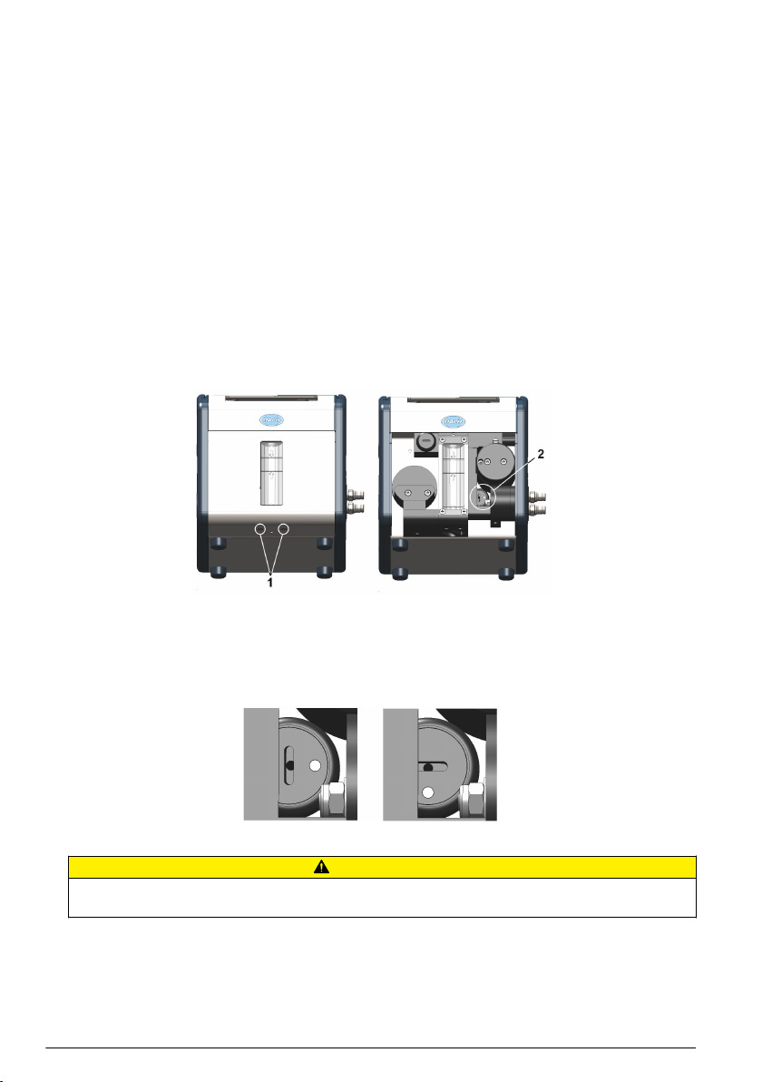
Reconnect battery power
For safety reasons, the battery pack will not be connected during shipment. Once the instrument has
been unpacked, the battery power should be reconnected using the following procedure:
1. Tilt the instrument towards the rear, to reveal two screws underneath (No. 1) that hold the
instrument front panel in place.
2. Using the cross screwdriver supplied in the tool kit, unscrew and remove these screws. Lift off the
front panel to reveal the internal battery power switch (No. 2).
3. Using the long-bladed flat-head screwdriver supplied in the tool kit, turn the switch a quarter of a
turn clockwise to reconnect the battery power. The diagrams below show the switch in the OFF
position as delivered (left) and in the ON position (right).
4. Replace the front panel and secure back in place with the two screws.
C A U TI O N
To avoid any damage to the instrument, it will be necessary to perform the above procedure in reverse (i.e.
turn the connection OFF) prior to any future transportation of this instrument.
Instrument switches and connectors
The following diagrams illustrate the side views of the instrument and their key features:
English
7
Page 8
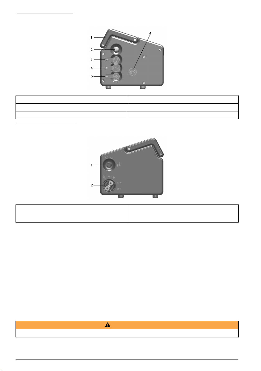
Figure 1 Left side view
1 Handle 4 USB connection
2 Instrument ON/OFF switch 5 External power supply connection
3 RS232 connection 6 Card identification system (option not yet available)
Figure 2 Right side view
1 Sample flow adjustment valve 2 Sample flow valve with inlet and outlet connections
(the sample inlet is at the top of the valve and the
outlet at the bottom).
Sample flow valve
The sample flow valve has three positions:
• Sample line PURGE
• Sample flow ON
• Sample flow OFF
The PURGE position is used to clear the sample line of any build up of air bubbles. For a thorough
purge, it is recommended to keep the valve in this position for 5 seconds. During this operation, the
sample flows directly from the inlet tubing to the outlet tubing. All measurements are suspended
during this time as the sample does not come into contact with the sensor.
The ON and OFF positions turn the sample flow on and off respectively.
Instrument connections
External power
W A R NI N G
When using an external power supply to power the instrument, ensure the external power socket is earthed.
In addition to the internal rechargeable battery pack, the instrument can be powered by an external
power source using the supplied adapter and cable. Connect the adapter to the power supply
8
English
Page 9

connection socket on the instrument (No. 5 in Figure 1 on page 8), and plug into an external power
supply socket.
Note: When the instrument is connected to an external power source, the internal battery pack is automatically
recharged.
RS232 connection
This connection can be used to download measurement data and for real-time monitoring of the
measurements.
The data sent to the PC via this link is identical in format and content to that stored in the
measurement file on the instrument and which can be transferred using the USB mass storage
device (see Exported files on page 19 for details).
USB connection
The USB connection (No. 4 in Figure 1 on page 8) is used for exporting and importing data from and
to the instrument. Tables can be set up on the PC using the 3100 PC software application and then
uploaded to the instrument using a USB mass storage device.
In addition, tables can be exported from the instrument to the USB storage device and then imported
to other 3100 instruments to standardize configurations.
For more details on this, refer to Import / Export on page 18.
Connecting sample lines
Measurements can be taken on a continuous or sample by sample basis. In either mode, the
instrument must be connected to the sample line as follows:
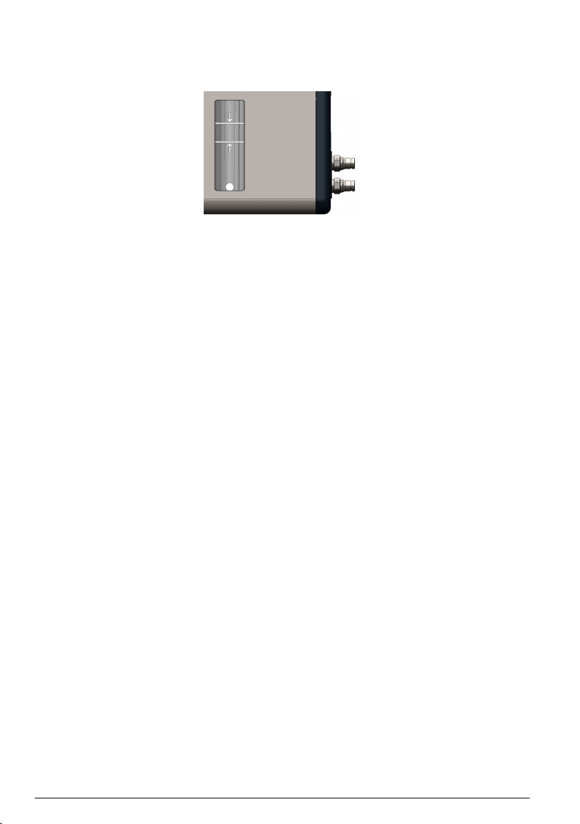
1. The sample inlet and outlet connections on the instrument are located on the ON/OFF sample
flow valve (No. 8 in Figure 2 on page 8 and enlarged in the diagram below):
1 Sample inlet 2 Sample outlet
2. Connect the inlet and outlet tubing to the sample source and to the drain, respectively. The
diagram above, shows the valve in the OFF position. To turn the sample flow fully ON, turn the
valve counter-clockwise until it clicks into position (about 1/8th of a turn). To remove any residual
air bubbles from the sample line, turn the valve to the PURGE position for 5 seconds before
turning to the ON position.
Note: A length of stainless steel tubing is supplied in the tool kit (4mm instrument version only) and can be
used instead of the plastic tubing on the outlet valve if the pressure in the instrument is high enough to cause
excessive movement of the plastic tubing.
3. If the sample contains particles, it is recommended to use a filter on the inlet tube to avoid any
clogging of the sample flow. The filter (including a box of 10 meshes) is contained in the tool kit
supplied with the instrument. It is also available separately as spare part number DG33216 (4mm
instrument), DG33317 (6mm instrument) or DG33318 (1/4 inch instrument) and the set of
10 meshes as spare part number DG33217.
4. Control the sample flow using the adjustment valve (No. 7 in Figure 2 on page 8) located above
the sample flow valve.
Flow rate guidelines:
• For cans and bottles the minimum recommended flow rate is 150mL/min. For small volume
packages a lower flow rate can be used but this should not be below 100mL/min.
English
9
Page 10
• For tank and in-line applications the recommended flow rate should be above 200mL/min and
up to a maximum of having the flow adjustment valve fully open.
Note: The flow rates indicated with arrows on the flow meter (as illustrated below) are approximately
150mL/min (lower arrow) and 200mL/min (upper arrow). The silver bead gives an indication of the flow rate.
PC software installation
The instrument is delivered with default user and measurement configuration tables. However, to
personalize the instrument by setting up your own tables you will need to use the PC software which
is included on the USB key supplied with the tool kit.
Install the PC software by inserting the USB key into your PC and running the setup program
(entitled setup.exe) from the directory Orbisphere 3100\Installation Files\PC Software on the USB
drive. Follow the on-screen instructions and the software will be installed on your hard disk in a new
directory: C:\Program Files\Hach Lange\3100 PC Software\.
Once the software has been installed, click on the desktop icon on the PC to launch the application.
Create new user table
From the application’s File menu, select New and then User Table.
A default user is created automatically, with an ID of “0”, a User Name of “Default”, and a level of
“User”. None of these fields can be changed. The password is set automatically to “1234”, but this
can be changed.
Use the Add option to add new users, and Delete to remove existing users. Copy and Paste can
also be used to add new users, and Cut can be used to delete existing users. Double click on a field
to edit the contents.
Create new measurement configuration table
From the application’s File menu, select New and then O2 Instrument to create a new
measurement configuration table.
A default entry is created automatically, with an ID of “0”, a Location Name and Product Name of
“Default”. None of these fields can be changed.
Use the same functionality as described for the user table, to add entries to the table.
Transfer files to the instrument
When the two tables have been populated, they can be transferred to the instrument using a USB
storage device (typically a USB key).
1. From the PC copy the files to the USB storage device in a top-level directory of 3100. The files
will typically be located in: C:\Program Files\Hach Lange\3100 PC Software\ with file
extensions of .cdm (for measurement configurations) and .ndu (for user tables).
Note: It is important that the file name extensions (.cdm and .ndu) are not changed as they will not be
recognized by the instrument software. Similarly, the files must be located in a top-level directory of 3100.
2. With the instrument switched ON, insert the USB storage device into the USB connection on the
left side of the instrument, and press the USB icon on the instrument front panel.
3. The first screen is for exporting files from the instrument to a USB storage device, so press the
right arrow to move to the next screen.
10
English
Page 11

4. The next screen is the Import User Table screen. The user table will be recognized by the
instrument and the file name displayed in the highlighted box. If more than one user table is on
the USB storage device, press the Enter key to view a list of all the user tables, and use the
up/down arrows to scroll through the list. Press the Enter key to select. When a table has been
selected, press the down arrow key until the Import File text is highlighted and press the Enter
key to import the file. On completion, a message will appear saying the instrument will have to be
turned off and on again for the new table to take effect, but as the measurement configuration
table is still to be imported this message can be ignored at this stage.
5. Press the right arrow to move to the Import Measurement Configurations screen. As with the
user table, select the measurement configuration table to import and press the down arrow key
until the Import File text is highlighted. Press the Enter key to import the file. Again, on
completion, a message will appear saying the instrument will have to be turned off and on again
for the new table to take effect.
6. As both tables have now been transferred to the instrument, turn the instrument OFF and then
back ON again for the new tables to take effect. When switched ON the two default table entries
will be loaded (i.e. default user and default measurement configuration).
User interface
Keypad and function keys
1 Cancel key 5 Enter key
2 USB key 6 RFID key
3 Sample or continuous mode key 7 Measurement key
4 Arrow keys
The user interface of the instrument consists of a display screen, 6 function keys and a set of 4 arrow
keys in the center. A green light at the bottom left of the keypad indicates if the instrument is ON. No
light indicates the instrument is OFF. The keypad is touch sensitive and will respond to each key
being pressed. As the key is touched a blue light will be appear underneath to indicate selection of
that key. If a key is selected that is not available or has no meaning during the current operation, then
the key will be displayed above the measurement value with a line drawn through it.
Note: The keypad can be locked and unlocked pressing the keys RFID, USB and RFID in sequence.
The keys have the following functions:
• Cancel data input.
• Exit from a menu and display the measurement screen.
• Display the main menu.
• Select an option.
• Validate the input and go on to the next step.
English 11
Page 12
• Import data from a USB mass storage device.
• Export data to a USB mass storage device.
• Card identification system (not yet available).
• When pressed twice in quick succession a screenshot will be taken (maximum of 10) that can be
transferred to a USB key using the Import / Export option from the Main Menu.
• Define if measurements are in sample or continuous mode. Continuous mode displays the bottle
symbol with a cross through it in the top right of the measurement screen. Sample mode displays
the bottle symbol without the cross.
• When in sample mode use this icon to Start/Stop measurements. When started the bottle symbol is
shown in green. When stopped the symbol is greyed out and a “Measurement stopped” message
displayed.
• Up arrow - Scroll up through a list or menu.
• Down arrow - Scroll down through a list or menu.
• Left arrow - Go back to the previous screen (or data element) in sequence.
• Right arrow - Go to the next screen (or data element) in a sequence.
Data entry
To select a data item from a list, use the up and down arrow keys to highlight the required value,
followed by the Enter key to select it.
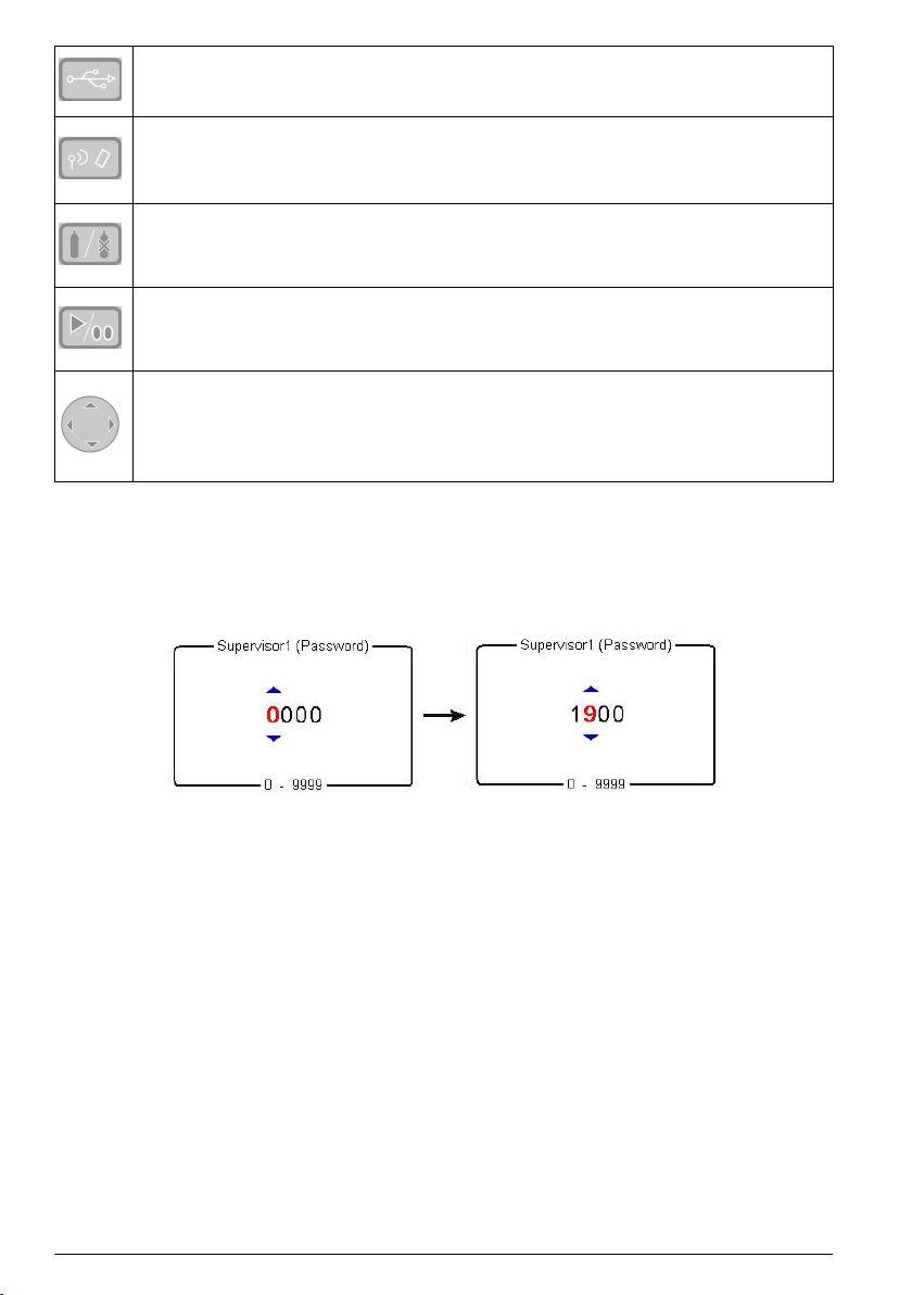
When required to enter data (e.g. a password in the following example), a screen will be displayed
showing the field default value (0000) and the valid range (0 - 9999) below it.
The first character will be highlighted in red with arrows above and below. Press the up and down
arrow keys to increase or decrease the value. When the correct value is showing, press the right
arrow key to move to the next character and enter that value until all characters have been entered.
User access
Two access levels are available:
• User - basic measurement functions
• Supervisor - password protected with access to additional views and the Main Menu
From the measurement screen, press the right arrow key until the list of users stored in the
instrument is displayed. Standard users will be displayed in green and supervisors in blue.
Note: These user lists are defined by the user on the PC (see Create new user table on page 10) and imported into
the instrument (see Transfer files to the instrument on page 10).
Press the up and down arrow keys to scroll through the list of users. When the required one is
highlighted press the Enter key to select it. If a supervisor level user is selected a password will be
required (by default Supervisor1 is 5678). On completion, the display returns to the measurement
screen.
12
English
Page 13

Standard measurement display
1 Instrument date and time 7 Battery life remaining
2 Measurement location and product name 8 USB symbol indicates USB key attached
3 User name 9 Measurement mode (continuous shown)
4 Sample temperature 10 High level alarm value (if set)
5 Measured gas 11 Low level alarm value (if set)
6 Measurement unit 12 Measurement value
• The user name will be displayed in green for a standard user, or blue for a supervisor
• The battery life remaining will not be displayed if using mains power supply, instead the icon will
show the battery recharging symbol
• The measurement value is normally displayed in blue, but will be displayed in red if it is outside the
high or low value alarm limits
• If measurement is in sample mode, the bottle icon is displayed at the top right of the screen. If
measurement mode is set to continuous, the bottle icon will be displayed with a cross through it
• The measurement display is refreshed every 5 seconds
Graphical measurement display
To access this display from the standard measurement display screen, press the right arrow key on
the keypad until the graphic screen is displayed:
This screen gives a graphical representation of the measurement with the numeric value of the
measurement displayed at the end of the curve. The above example shows the measurement in
sample mode.
The numeric measurement value at the end of the curve is refreshed every 5 seconds. The curve is
refreshed every 5 seconds in sample mode. In continuous mode, the refreshment rate is the same as
that defined as the storage interval parameter.
The graphic timescale is displayed at the bottom of the screen. This value can be increased or
decreased (4 zoom levels) by pressing the up and down arrows on the keyboard. These values are
also dependant on the storage interval parameter; the greater the storage interval, the greater the
available timescale.
The measurement scale is calculated automatically with the maximum and minimum values
displayed at the top and bottom of the y axis respectively.
In sample mode, a square symbol is displayed to denote the end of the measurement . This is
displayed in green if the stop criteria are met, or red to denote an erroneous measurement.
English
13
Page 14
The color of the curve has the following meaning:
• Grey (normal): The channel is out or the measurement is out of range
• Green (bold): The channel is being calibrated
• Grey (bold): The measurement has not started (sample mode only)
• Red (bold): An alarm has been activated
• Blue (bold): Normal measurement
Measurement configuration list
From the measurement screen, press the right arrow key until the list of measurement configurations
stored in the instrument is displayed.
Note: These configurations are defined by the user on the PC (see Create new measurement configuration table
on page 10) and imported into the instrument (see Transfer files to the instrument on page 10). Only the default
configuration (ID0) can be edited by the user from the instrument. To do this the user must be logged on at
supervisor level and the default parameters can then be edited from the Main Menu as described in Default
measurement configuration settings on page 17.
Press the up and down arrow keys to scroll through the list of measurement configurations. When the
required one is highlighted press the Enter key to select it. The selected configuration details will be
displayed on screen.
Press the Enter key again to select this configuration and return to the measurement screen, or
Cancel to reject it and return to the measurement configuration list screen.
Measurement alarms
If a problem occurs during measurement, the system will alternate every second between the
measurement screen and the error message screen.
The measurement value is displayed in red to indicate a measurement outside the pre-defined alarm
limits. The alarm low value on the right side of that screen is also displayed in red to indicate the
reason the measurement value is in error.
The error message screen gives the reason why the measurement is invalid.
Note: If the measured value goes back above this low value, the value is again displayed in blue and the error
message screen is no longer shown.
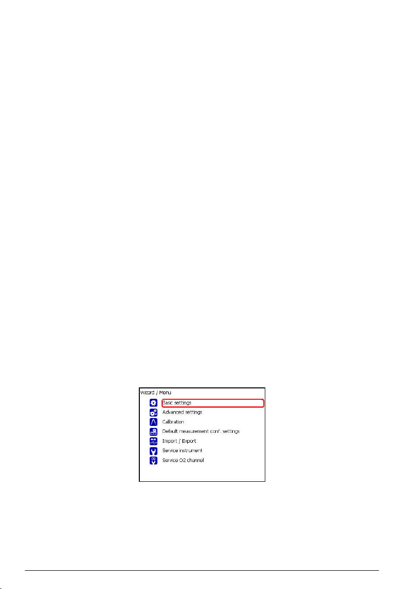
Main menu
The main menu is only available to users logged on at supervisor level.
To access the main menu from the measurement screen, press the Enter key on the main keypad to
display the following options:
Scroll through the menu using the up and down arrow keys. When the required option is highlighted,
press the Enter key to select it and display the sub option screens.
14
English
Page 15

Basic settings
1. Language selection
Option Description
Language Select the working language for the instrument from the list available
2. Date and time adjustment
Option Description
Date format Define the display format for the date (DD/MM/YY or MM/DD/YY)
Date Enter the day, the month and the year in the format defined above
Time format Enter the display format for the time using a 12 or 24 hour clock
Time Enter the hour and minutes in the format defined above
3. Backlight management
Option Description
Backlight level Enter the scale of brightness (max, comfortable, standard, economy or min)
4. Units management
Option Description
Pressure unit Choose the barometric pressure unit from the list available
Temperature unit Choose the temperature unit from the list available
Advanced settings
1. File measurement management
Option Description
Storage
mode
Choose from a rolling buffer or store once:
• Rolling buffer: When the file is full, the latest measurement set replaces the oldest one
continuously (first-in, first-out)
• Store once: When the file is full (5,760 positions), the recording of measurement stops
Storage
interval
Clear data Select this option to erase the measurement storage file
Define the interval for storing measurements from the list available.
The interval is in seconds with the number of hours of measurements available shown in
brackets e.g. 10s (16h) indicates measurements are stored every 10 seconds, which will
give 16 hours of continuous storage
Note: This parameter also defines the refreshment rate for the graphic measurement
display.
2. Communication
Option Description
RS232 Check the box if the RS232 link is required
Baud rate Select the baud rate from the list available
3. Miscellaneous
Option Description
Miscellaneous This option allows the default measurement configuration parameters to be restored
English 15
Page 16

Calibration
Barometric sensor calibration
1. The upper box shows the current barometric pressure as measured by the instrument. Using a
precision certified barometer, measure the barometric pressure in the location where the
instrument is used. If the values differ, enter the correct value in the box provided and select
Validate calibration
Gas sensor calibration
There are two calibration modes available
• Zero calibration
• High level adjustment
The zero calibration method is the best method to guarantee the sensor specifications.
To get more accurate measurements for samples with higher oxygen concentrations (above 1%
oxygen which corresponds to about 400 ppb dissolved O2) a high level adjustment can be performed
using a gas mixture containing 2% oxygen. However, this should not be done without first ensuring
the zero point is accurate (i.e. by performing a zero calibration first).
Zero calibration
1. Rinse flow path with 20 mL of ethanol (EtOH) using the syringe and connectors supplied in the
tool kit
2. Connect a cylinder of oxygen free gas (minimum 99.9% purity) to the instrument and adjust the
flow to approximately 100 mL/min
3. Let the oxygen free gas run through the instrument for 5 minutes
4. Press the Enter key to start the calibration
5. Wait until the Signal in range and Stability reached fields display Yes which indicates the
calibration is within acceptable limits. The Calibration possible field should also display Yes at
this point. Press the Enter key to complete the calibration
6. Accept (OK) or reject (Cancel) the new calibration data
High level adjustment
There are three possible modes for high level adjustments:
• Using a reference gas mixture (gas cylinder)
• Using a known oxygen sample (reference sample)
• Enter a factory parameter provided by Hach Lange (this option is only required when the sensor
spot has been replaced)
If the calibration mode displayed is not the required mode, then press the Enter key and select the
required mode from the three options available in the drop-down list:
• Factory parameter
• Reference sample
• Ref. gas bottle
Factory parameter
1. In the Calibration mode window select Factory parameter
2. Scroll down to the Reference value window and enter the factory parameter as found on the
package of the LDO spot (model number DG33218)
3. Scroll down to the Start Calibration window and press the Enter key to start the calibration
4. Accept (OK) or reject (Cancel) the new calibration data
16
English
Page 17

Reference sample
1. Run the reference sample through the instrument and adjust the flow to approximately
150 mL/min.
2. In the Calibration mode window select Reference sample
3. Scroll down to the Reference value window and enter the oxygen value of the sample
4. Let the sample run through the instrument for 5 minutes to stabilize the measurement
5. Scroll down to the Start Calibration window and press the Enter key to start the calibration
6. Wait until the Signal in range and Stability reached fields display Yes which indicates the
calibration is within acceptable limits. The Calibration possible field should also display Yes at
this point. Press the Enter key to complete the calibration
7. Accept (OK) or reject (Cancel) the new calibration data
Ref. gas bottle
1. Rinse flow path with 20 mL of ethanol (EtOH) using the syringe and connectors supplied in the
tool kit
2. In the Calibration mode window select Ref. gas bottle
3. Scroll down to the Reference value window and enter the oxygen value of the reference gas in
%Vbar
4. Connect the gas sample to the instrument and adjust the flow to approximately 100 mL/min.
5. Let the gas mixture run through the instrument for 5 minutes to stabilize the measurement
6. Scroll down to the Start Calibration window and press the Enter key to start the calibration
7. Wait until the Signal in range and Stability reached fields display Yes which indicates the
calibration is within acceptable limits. The Calibration possible field should also display Yes at
this point. Press the Enter key to complete the calibration
8. Accept (OK) or reject (Cancel) the new calibration data
Default measurement configuration settings
1. Instrument settings
Option Description
Instrument mode Select between continuous or sample mode.
Continuous mode is typically used for process measurement, whereas sample mode is
aimed at lab measurements of small volume individual samples such as cans, bottles,
etc.
Sample type Select the sample type from the list available
2. O2 channel settings
Option Description
O2 gas unit type Select the gas unit type from the list available
O2 gas unit Select the display unit from the list available
English 17
Page 18

Option Description
O2 high alarm Check the box to set the measurement high alarm.
If set, enter the high level value to trigger the alarm. When measurements exceed this
value an alarm will be triggered
O2 low alarm Check the box to set the measurement low alarm.
If set, enter the low level value to trigger the alarm. When measurements fall below this
value an alarm will be triggered
3. O2 advanced settings
Option Description
O2 measurement offset If required, enter a value (positive or negative) for the measurement offset. This
value will be used to adjust the measurement accordingly
Import / Export
Note: To import files into the instrument from a USB mass storage device, they must be under a top-level directory
of 3100 for them to be recognized.
1. Export files
Option Description
Export
files
2. Import user table
Option Description
Import
user table
3. Import measurement configuration table
Option Description
Import
measurement
configuration
table
This option allows you to export a number of different files to a USB mass storage device. Once
written to the USB device, it can then be used to load these files to other 3100 instruments or to
a PC.
Make sure a USB device is connected and then press the Enter key to start the process. A
progress bar is displayed at the bottom of the screen.
Wait until the export complete message is displayed on screen before removing the USB
device.
This option allows you to import user tables from a USB mass storage device. These tables
could be exported from other 3100 instruments or from the 3100 software application installed
on your PC. The tables are recognized by having an extension of .ndu. If more than one table is
found on the device, you will need to select the table you want from the list.
Press the down arrow key to highlight the Import File option and press the Enter key to start
the process. You will need to restart the instrument before the new table takes effect.
This option allows you to import measurement configuration tables from a USB mass
storage device. These tables could be exported from other 3100 instruments or from the
3100 software application installed on your PC. The tables are recognized by having an
extension of .cdm. If more than one table is found on the device, you will need to select
the table you want from the list.
Press the down arrow key to highlight the Import File option and press the Enter key to
start the process. You will need to restart the instrument before the new table takes
effect.
18 English
Page 19

4. Import solubility parameters
Option Description
Import
solubility
parameters
This option allows you to import solubility parameters from a USB mass storage device.
The tables are recognized by having an extension of .sol. If more than one file is found on
the device, you will need to select the file you want from the list.
Press the down arrow key to highlight the Import File option and press the Enter key to
start the process. You will need to restart the instrument before the new table takes effect.
5. Import instrument basic settings
Option Description
Import
instrument
basic settings
This option allows you to import instrument user settings from a USB mass storage
device. The tables are recognized by having an extension of .ius. If more than one file is
found on the device, you will need to select the file you want from the list.
Press the down arrow key to highlight the Import File option and press the Enter key to
start the process. You will need to restart the instrument before the new table takes effect.
Exported files
The following files will be automatically exported from the instrument to the USB mass storage device
under a top-level directory of 3100:
• All measurement configuration tables (*.cdm)
• All user tables (*.ndu)
• All solubility tables (*.sol)
• All user settings tables (*.ius)
• Instrument configuration details (InstrumentConf.txt)
• Measurement details (Measurements.txt)
• Instrument model details (Model.txt)
• A number of internal files (*.dat)
The following files can be found under sub-directories CalibrationReports and Screenshots:
• Calibration reports (O2CalibrationReport*.txt)
• Screenshots (View*.bmp)
The text files (*.txt extension) are in a readable format for your PC. Most document editors can be
used to open these files, as well as spreadsheet and other reporting tools.
The measurement configuration tables and user tables can be modified using the PC software (see
PC software installation on page 10).
Service instrument
1. Board information
Option Description
Board information This option is useful for troubleshooting purposes and displays information about the
mother board, measurement board and battery
2. Temperature checking
Option Description
Temperature checking This option is useful for troubleshooting purposes and displays the temperature
readings of the measurement board, pigtail, battery pack and sample
English 19
Page 20

3. Sample temperature calibration
Option Description
Sample temperature
calibration
You will need a sensor simulator for this option. Follow the on-screen
instructions to calibrate the sample temperature
4. Miscellaneous
Option Description
Enable raw
data logger
Activate
service timer
Note: The total uptime of the instrument is displayed at the bottom of the screen.
Check the box to enable the capture of raw data which is useful for troubleshooting
purposes
Check the box to activate the service timer option.
When activated, the instrument will automatically remind the user when the next sensor
service is due.
Enter the Nb of days between services in the box provided. This defines the due date of
the next sensor service.
If activated, select the Reset service timer option each time the instrument has been
serviced. This automatically sets the Last service date parameter to the current date.
Service O2 channel
1. O2: Calibration parameters
Option Description
O2: Calibration
parameters
2. O2: DC measurement parameters
Option Description
O2: DC measurement
parameters
3. O2: AC diagnostic parameters
Option Description
O2: AC diagnostic
parameters
4. O2: Calibration timer
Option Description
Activate
calibration
timer
Check the box to activate the calibration timer option.
When activated, the instrument will automatically remind the user when the next sensor
calibration is due.
The Last calibration date parameter is shown for information. This is automatically
updated each time a calibration is performed on the sensor.
Enter the Nb of days between calibrations in the box provided. This defines the due
date of the next sensor calibration.
This option is useful for troubleshooting purposes and will display a number of
values associated with the measurement channel
This option is useful for troubleshooting purposes and will display the
values of the fluorescent and reference LED current
This option is useful for troubleshooting purposes and will display the values of
the fluorescent and reference amplitude and phase, plus the phase shift value
20 English
Page 21

Maintenance
Maintenance schedule
This following table shows the recommended maintenance schedule for the ORBISPHERE
3100 instrument. This proposed schedule should be modified according to operating conditions.
Interval Item
Daily Clean outside of the instrument with a damp cloth and run clean water through the
Weekly Clean outside of the instrument with a damp cloth and run 20 mL of ethanol (EtOH)
Monthly Run warm water through the instrument followed by 20 mL of ethanol (EtOH).
Yearly Calibrate the oxygen sensor
Every 4 years Replace the oxygen sensor spot and perform a sensor calibration
Batteries
The instrument is designed to operate on rechargeable batteries. When battery power becomes low,
the batteries can be recharged by connecting the instrument to the mains power supply using the
supplied power adapter and cable. When connected, the batteries are automatically recharged.
Sensor
If the instrument is being powered by mains power, disconnect the instrument from the power supply before
carrying out this procedure.
Based on instrument usage of 8 hours/day and 365 days/year, the sensor spot will need to be
replaced about once every 4 years. The procedure is very simple and takes no more than a few
minutes.
Before starting, ensure you have the replacement flow chamber assembly as supplied with the
maintenance kit (part number DG33228). Switch the instrument OFF and make sure it is
disconnected from any mains power supply.
Follow these instructions referring to the illustrations below:
instrument to clean the internal passageways
through the instrument to clean the internal passageways
Dry by flowing dry air or N2 through the instrument
W A R NI N G
1. Remove the front panel from the instrument by unscrewing the 2 screws underneath the
instrument (No. 1) that secure it in place. Use the cross screwdriver supplied in the tool kit for this
purpose.
2. Once removed, the flow chamber assembly (No. 2) can be seen located to the right of the flow
meter.
English
21
Page 22

3. Remove the holding screw from the flow chamber assembly.
4. Holding the assembly between thumb and forefinger, gently ease it out of the instrument and
discard.
5. Replace the assembly with the new one from the maintenance kit, Put the new assembly back in
place in the instrument and secure with the holding screw. A guide rod is in place to ensure
correct positioning.
6. Replace the front guard and secure in place with the 2 screws underneath the instrument.
7. After changing the spot, a sensor calibration must be performed before using the instrument for
measurement purposes.
Troubleshooting
Measurement
Symptom Possible solution
Display appears to be frozen - no
active cursor
Display appears to be frozen out
of range
Degassing in flow meter Adjust flow rate to between 150 and 200 mL/min
Measurement spiking Ensure all tubing is tightly and correctly connected to the sample inlet and
Response time too long Use tubes supplied with instrument (low O2 permeable material)
Channel out Change LDO spot
Silver bead does not move freely
in the sample
Check measurement mode (continuous or sample)
When “Out of Range”, measurement interval is 60 seconds
Verify that the filter (if using) is not blocked
outlet connections
Remove any residual air bubbles from the sample line by turning the sample
inlet/outlet valve to the PURGE position for 5 seconds
Check flow rate and connections
Prior to package sampling, purge the piercer with N2 gas
Perform the monthly cleaning procedure
Contact Hach Lange service
Perform the monthly cleaning procedure
Zero calibration
Symptom Possible solution
Signal not in range - calibration
value very different from last
calibration value
Stability not reached - signal not
stable
22 English
Open sample flow adjustment valve completely
Calibration gas has too much oxygen, use quality 50 N2 or CO2 bottle
Oxygen leaks between reference bottle and instrument. Can be checked by
increasing gas flow rate and checking partial pressure (mbar) decrease
Wait for stability and check N2 gas flow rate
Presence of liquid on LDO membrane. Check presence of liquid in flow
meter and if so, dry by injecting 20 mL of EtOH then 5 minutes of N2 gas
Page 23

High level calibration
Symptom Possible solution
Signal not in range - calibration
value very different from last
calibration value
Stability not reached - signal not
stable
Check your theoretical sample O2 content and reference configuration
If gas bottle calibration, completely open the sample flow adjustment valve
to avoid gas overpressure, hence wrong O2 concentration
Wait for stability and check reference gas or liquid flow rate
Presence of liquid on LDO membrane. Check presence of liquid in flow
meter and if so, dry by injecting 20 mL of ethanol (EtOH) then 5 minutes of
N2 gas
Instrument storage when not used
General guidelines
When not in use, ensure the instrument is turned OFF by pressing the ON/OFF switch (No. 2 in
Figure 1 on page 8) until the green indicator light is extinguished.
C A U TI O N
If the instrument is to be stored in an environment where the temperature is likely to be 0°C (32°F) or below, then
to avoid any damage to the instrument make sure there is no liquid inside. Do this by first running warm water
through the instrument and dry by flowing dry air or N2 through it. Then turn the sample flow valve (No. 8 in
Figure 2 on page 8) to the OFF position.
Short term storage
For short term storage (between measurements or up to a maximum of 6 hours), leave the sample in
the instrument by turning the sample flow valve (No. 8 in Figure 2 on page 8) to the OFF position.
Overnight or weekend storage
When storing the instrument overnight or over a weekend, run clean water through the instrument to
prevent passageways from becoming clogged and then turn the sample flow valve (No. 8 in Figure 2
on page 8) to the OFF position. Wipe down the outside of the instrument with a clean damp cloth.
Long term storage
For long term storage (more than 1 week), run warm water through the instrument followed by 20 mL
of ethanol (EtOH). Dry by flowing dry air or N2 through the instrument, and then turn the sample flow
valve (No. 8 in Figure 2 on page 8) to the OFF position. Wipe down the outside of the instrument with
a clean damp cloth. It is recommended to fully charge the battery prior to any long term storage.
Note: If the instrument has been in storage for more than 4 weeks, remember to fully recharge the battery pack
before use.
English
23
Page 24

Spezifikationen
Die Spezifikationen können ohne Vorankündigung Änderungen unterliegen
Spezifikation Details
Probe nicht entzündbare gasförmige oder flüssige Proben
Probentemperatur -5 bis + 45°C
Probendruck 0 bis 10 bar (0 bis 140 psi)
Arbeitsbereich 0 bis 2000 ppb
Genauigkeit ± 0,8 ppb oder ± 2% der Anzeige, je nachdem, welcher Wert größer ist
Wiederholbarkeit r95 ± 0,4 ppb oder ± 1% der Anzeige, je nachdem, welcher Wert größer ist
Erfassungsgrenzen 0,6 ppb
Reaktionszeit t90 Im Allgemeinen weniger als 15 Sekunden, die tatsächliche Zeit hängt aber von dem
Messungen bis zu 5.760 Messungen 8 Stunden Daten bei einer Probenfrequenz von
Anzeigeeinheiten O2 Konzentration ppb, ppm, μg/L, mg/L, mL/L, %O2, %air, %Vbar, ppmVbar
Betriebsbedingungen Umgebungstemperatur -5 bis + 45°C
Gewicht 3,4 kg
Abmessungen (L x B xH)200 x 170 x 190 mm
Probenverfahren ab.
5 Sekunden
96 Stunden Daten bei einer Probenfrequenz von 1 Minute
Druck mbar, bar, Pa, hPa, kPa, MPa, psia, psig, atm, kgf/cm2
Temperatur °C, °F, K
Relative Feuchtigkeit 0 bis 95% nicht kondensierend für Temperaturen unter
30°C
0 bis 70% nicht kondensierend für Temperaturen von
30 bis 45°C
Wasserdichtigkeit IP66-Gehäuse aus Edelstahl mit Seitenteilen aus Polykarbonat
Stromversorgung Aufladbarer Akkupack: Li-Ion 46 Wh
Externer Netzeingang: 100 - 240 V AC ±10%, 47 - 63 Hz
Externer Netzausgang: 12 VDC, 3,75 A
Hinweis: Die externe Stromversorgung verfügt nicht über die Schutzart IP66.
Batterieautonomie > 10 Stunden bei kontinuierlichen Messungen
Batterieladezeit < 4 Stunden
Hinweis: Die Ladezeit verlängert sich um 20% bei Temperaturen über 35°C.
EMV-Anforderungen EN61326-1: EMV-Richtlinie
User Guidance for EMC Class B Equipment
가정용을 포함하는 EMC 등급 B 장치에
Korean registration
대한 사용자 지침
사용자안내문
B 급 기기 ( 가정용 방송통신기자재 )
이 기기는 가정용 (B 급 ) 전자파적합기기로서 주로 가정에서 사용하는 것을 목적으로
하며 , 모든 지역에서 사용 할 수 있습니다.
24 Deutsch
Page 25

Spezifikation Details
CE-Konformität EN61010-1: Niederspannungsrichtlinie
Sicherheitsnorm IEC/UL/CSA 61010-1
Überspannungskategorie Kategorie II
Digitalanzeige TFT Farbdisplay 72 x 54 mm
Schnittstellen 1 x USB (5V DC) Ein-/Ausgang Massenspeicher
1 x RS232 (0-5 V) Serielle Ausgabe
Allgemeine Informationen
Der Hersteller ist nicht verantwortlich für direkte, indirekte, versehentliche oder Folgeschäden, die
aus Fehlern oder Unterlassungen in diesem Handbuch entstanden. Der Hersteller behält sich
jederzeit und ohne vorherige Ankündigung oder Verpflichtung das Recht auf Verbesserungen an
diesem Handbuch und den hierin beschriebenen Produkten vor. Überarbeitete Ausgaben der
Bedienungsanleitung sind auf der Hersteller-Webseite erhältlich.
Sicherheitshinweise
H I N WE IS
Der Hersteller ist nicht für Schäden verantwortlich, die durch Fehlanwendung oder Missbrauch dieses Produkts
entstehen, einschließlich, aber ohne Beschränkung auf direkte, zufällige oder Folgeschäden, und lehnt jegliche
Haftung im gesetzlich zulässigen Umfang ab. Der Benutzer ist selbst dafür verantwortlich, schwerwiegende
Anwendungsrisiken zu erkennen und erforderliche Maßnahmen durchzuführen, um die Prozesse im Fall von
möglichen Gerätefehlern zu schützen.
Bitte lesen Sie dieses Handbuch komplett durch, bevor Sie dieses Gerät auspacken, aufstellen oder
bedienen. Beachten Sie alle Gefahren- und Warnhinweise. Nichtbeachtung kann zu schweren
Verletzungen des Bedieners oder Schäden am Gerät führen.
Stellen Sie sicher, dass die durch dieses Messgerät bereitgestellte Sicherheit nicht beeinträchtigt
wird. Verwenden bzw. installieren Sie das Messsystem nur wie in diesem Handbuch beschrieben.
Bedeutung von Gefahrenhinweisen
G E F AH R
Kennzeichnet eine mögliche oder drohende Gefahrensituation, die, wenn sie nicht vermieden wird, zum Tod oder
zu schweren Verletzungen führt.
Kennzeichnet eine mögliche oder drohende Gefahrensituation, die, wenn sie nicht vermieden wird, zum Tod oder
zu schweren Verletzungen führen kann.
Kennzeichnet eine mögliche Gefahrensituation, die zu geringeren oder moderaten Verletzungen führen kann.
Kennzeichnet eine Situation, die, wenn sie nicht vermieden wird, das Gerät beschädigen kann. Informationen, die
besonders beachtet werden müssen.
W A R NU N G
V O R SI C H T
H I N WE IS
Sicherheits-Vorsichtsmaßnahmen
Der Sauerstoffanalysator 3100 wird mit einer Lithiumbatterie betrieben. Um den sicheren Betrieb des
Geräts zu gewährleisten, lesen Sie bitte die nachfolgend aufgeführten Sicherheitshinweise
aufmerksam durch.
Beachten Sie bei der Verwendung (einschließlich Lagerung):
Deutsch
25
Page 26

W A R NU N G
Brand- und Explosionsgefahr
• Die Batterie kann in einem Temperaturbereich von -10 bis 60°C betrieben, gelagert und entsorgt werden. Bei
der Verwendung außerhalb dieses Bereichs:
• besteht Brandgefahr, weil die Batterie aufbrechen und auslaufen kann.
• kann sich die Lebensdauer der Batterie verkürzen.
• Schalten Sie das Gerät sofort aus, wenn beim Benutzen oder Aufladen der Batterie ein ungewöhnlicher
Geruch oder Rauch entstehen oder das Batteriegehäuse ungewöhnlich heiß wird. Kontaktieren Sie in dem Fall
immer den örtlichen Hach Lange Kundendienst.
• Vermeiden Sie den Augenkontakt mit eventuell ausgelaufener Batterieflüssigkeit im Gehäuse. Reiben Sie
niemals die Augen. Spülen Sie die Augen gründlich mit Wasser aus und suchen Sie sofort einen Arzt auf.
Batterieflüssigkeit kann schwerwiegende Verletzungen an den Augen verursachen, wenn diese nicht
behandelt werden.
• Stellen Sie den Analysator und dessen Batterien niemals in Mikrowellenherde, Hochdruckbehälter oder
Induktionskochgeräte.
Brand- und Explosionsgefahr
• Schalten Sie den Analysator sofort aus, wenn die Batterie ausgelaufen ist oder aufgrund von
Verschleißerscheinungen oder unsachgemäßem Gebrauch Flüssigkeit in das Batteriefach eindringt.
• Bei unsachgemäßem Gebrauch kann die Batterie zu heiß werden, explodieren oder sich entzünden und
dadurch schwerwiegende Verletzungen verursachen.
• Die interne Batterie nicht mit Flüssigkeiten wie Wasser, Bier oder Salzwasser in Berührung bringen. Die
Batterie darf niemals feucht werden.
• Den Analysator oder die Batterie unter keinen Umständen modifizieren. Der interne Akku verfügt über
Sicherheits- und Schutzvorrichtungen, die, wenn sie beschädigt werden, eine starke Erhitzung, Explosion oder
Entzündung der Batterie verursachen können.
• Gerät und Batterie niemals in der Nähe von offenen Flammen, Öfen oder sonstigen Hitzequellen (über 60°C)
aufstellen. Gerät und Batterie niemals in die Sonne stellen oder bei heißem Wetter in Fahrzeugen verwenden.
Die Batterie kann sich erhitzen oder entzünden bzw. explodieren. Außerdem werden die Leistungen der
Batterie dadurch beeinträchtigt bzw. die Lebensdauer verkürzt.
W A R NU N G
Beachten Sie beim Aufladen der Batterie:
W A R NU N G
Brand- und Explosionsgefahr
Beim Aufladen der Batterie müssen folgende Hinweise beachtet werden. Bei Missachtung dieser
Sicherheitsvorschriften kann sie sich erhitzen oder entzünden bzw. explodieren und schwerwiegende
Verletzungen verursachen.
• Die Batterie kann in einem Temperaturbereich von 10 bis 45°C geladen werden. Wird die Batterie außerhalb
dieses Bereichs geladen, kann sich die Batterie erhitzen bzw. aufbrechen. Außerdem können sich die
Leistungen oder die Lebensdauer der Batterie reduzieren, wenn diese außerhalb des o. g. Temperaturbereichs
aufgeladen wird.
• Die Batterie nur mit dem mitgelieferten Ladegerät aufladen.
• Während des Aufladevorgangs den Analysator nicht in der Nähe von offenen Flammen oder in der Sonne
aufstellen. Zusätzliche Hitze kann zu einer Erhitzung der Batterie führen und die in die Batterie integrierten
Schutzschaltungen, die verhindern sollen, dass sich die Batterie entzündet, beschädigen. Die zusätzliche Hitze
kann aber auch dazu führen, dass sich die Schutzschaltungen aktivieren, wodurch verhindert wird, dass sich
die Batterie weiter auflädt.
• Unterbrechen Sie den Ladevorgang, wenn sich die Batterie nicht innerhalb der vorgegebenen Zeit aufgeladen
hat. Anderfalls kann sich die Batterie erhitzen oder entzünden bzw. explodieren. Treten beim Ladevorgang
Störungen auf, kontaktieren Sie bitte Ihren Hach Lange Kundendienst.
Hach Lange übernimmt keine Haftung für Störungen, die auf die Mißachtung der oben aufgeführten
Sicherheitshinweise zurückzuführen sind.
26
Deutsch
Page 27

Warnaufkleber
Bitte lesen Sie alle Aufkleber und Schilder, die am Produkt angebracht sind. Die Nichtbeachtung
kann zu Verletzungen von Personen oder Beschädigungen des Produkts führen. Im Handbuch
werden auf die am Gerät angebrachten Symbole in Form von Warnhinweisen verwiesen.
Dieses Symbol auf einem Produkt zeigt eine potenzielle Gefahr an, die zu ernsthaften Verletzungen
und/oder zum Tod führen kann. Der Benutzer soll dieses Handbuch bei der Bedienung des Geräts
und/oder für Sicherheitsinformationen verwenden.
Dieses Symbol auf einer Verkleidung oder Schranke des Produkts weist auf die Gefahr von
Stromschlägen hin und macht darauf aufmerksam, dass ausschließlich für die Arbeit mit
gefährlichen Spannungen qualifiziertes Personal die Verkleidung öffnen oder die Schranke
entfernen sollte.
Dieses Symbol auf dem Produkt weist auf das Vorhandensein von Bauteilen hin, die durch
elektrostatische Entladungen gestört werden können und macht darauf aufmerksam, dass mit
Vorsicht vorgegangen werden muss, um Schäden an diesen Bauteilen zu vermeiden.
Dieses Symbol weist darauf hin, dass das Instrument an Wechselstrom angeschlossen werden
muss.
Elektrogeräte, die mit diesem Symbol gekennzeichnet sind, dürfen in der Europäischen Union nicht
als Haushaltsabfall oder in öffentlichen Abfallentsorgungssystemen entsorgt werden. Altgeräte
können ohne zusätzliche Kosten für den Verbraucher an den Hersteller für die Entsorgung
zurückgegeben werden.
Produkte, die mit diesem Symbol gekennzeichnet sind, enthalten toxische oder gefährliche
Substanzen oder Elemente. Die Ziffer in diesem Symbol gibt den Umweltschutzzeitraum in Jahren
an.
Übersicht
Der ORBISPHERE 3100 ist ein tragbarer Analysator für die Messung der Sauerstoffkonzentration in
gasförmigen und flüssigen Proben. Bis zu 5.760 Messwerte können im Speicher abgespeichert und
für die zukünftige Analyse auf einen PC heruntergeladen werden.
Der Analysator ist in 3 verschiedenen Versionen lieferbar (4-mm-, 6-mm- und 1/4-Zoll-Anschlüsse)
Installation
Nehmen Sie den Analysator und die Zubehörteile vorsichtig aus der Verpackung. Prüfen Sie anhand
der Packliste, ob die Lieferung vollständig ist. Nehmen Sie eine Sichtprüfung des Analysators im
Hinblick auf eventuelle Transportschäden vor. Bitte wenden Sie sich umgehend an den Hersteller
oder Ihren Händler, falls etwas beschädigt ist oder fehlt.
Das Display wird durch einen Schutzfilm vor eventuellen Transportschäden geschützt. Entfernen Sie
den Schutzfilm vor der ersten Inbetriebnahme des Analysators.
H I N WE IS
Werkseitig wurde außerdem ein zweiter, weitaus stärkerer Schutzfilm auf das Display aufgebracht, um dieses vor
Beschädigungen und Feuchtigkeit zu schützen. Diesen Schutzfilm unter keinen Umständen entfernen!
Kontaktieren Sie bitte Ihre örtliche Hach Lange Vertretung, wenn dieser Schutzfilm Schäden aufweist.
Checkliste vor der Installation
1. Setzen Sie das Akkupack wie in Setzen Sie das Akkupack ein. auf Seite 28 beschrieben in das
Instrument ein.
2. Setzen Sie den Betriebsschalter des Geräts (Nr. 2 in Abbildung 1 auf Seite 29 auf EIN). Wenn
das Akkupack aufgeladen werden muss, schließen Sie das Gerät wie in Externe Stromspeisung
auf Seite 29 beschrieben an die Stromversorgung an.
Deutsch
27
Page 28
3. Lesen Sie zunächst den nachfolgenden Abschnitt Benutzeroberfläche auf Seite 32 des
vorliegenden Handbuchs, um sich mit den Betriebsfunktionen des Geräts vertraut zu machen.
4. Stellen Sie vor dem Abspeichern der Daten das Datum und die Uhrzeit der internen Uhr des
Instruments wie in Grundeinstellungen auf Seite 36 beschrieben ein.
5. Installieren Sie die 31000 PC-Software wie in Installation der PC-Software auf Seite 31
beschrieben auf Ihrem PC.
6. Richten Sie mithilfe der PC-Software eine neue Benutzertabelle wie in Neue Benutzertabelle
erstellen auf Seite 31 beschrieben ein.
7. Richten Sie mithilfe der PC-Software eine Messkonfigurationstabelle wie in beschrieben Neue
Messkonfigurationstabelle erstellen auf Seite 31 ein.
8. Laden Sie Benutzer- und Konfigurationstabelle wie in Dateien in das Instrument übertragen
auf Seite 32 beschrieben auf das Instrument.
Setzen Sie das Akkupack ein.
Aus Sicherheitsgründen wird das Akkupack für den Transport ausgebaut. Nach dem Auspacken des
Geräts setzen Sie das Akkupack wie im Folgenden wieder ein:
1. Kippen Sie das Gerät nach hinten. Jetzt sind die beiden unteren Befestigungsschrauben (Nr. 1)
des Frontpaneels sichtbar.
2. Lösen Sie die Schrauben mit dem im Tool-Kit enthaltenen Kreuzkopfschraubendreher und
entfernen Sie diese. Nehmen Sie das Frontpaneel ab. Jetzt haben Sie Zugriff auf den
Batterieschalter (Nr. 2).
3. Für den Ausbau des Akkupacks drehen Sie den Schalter mit dem im Tool-Kit enthaltenen
Flachkopfschraubendreher mit langer Klinge eine Viertelumdrehung im Uhrzeigersinn. In der
Abbildung sind links die Position OFF (bei Lieferung) und rechts die Position ON dargestellt.
4. Setzen Sie das Frontpaneel wieder ein und befestigen Sie es mit den zwei Schrauben.
V O R SI C H T
Um Schäden an dem Instrument zu vermeiden, muss der oben beschriebene Vorgang vor jedem Transport in
umkehrter Reihenfolge (d. h. Schalter auf OFF setzen) ausgeführt werden .
Schalter und Anschlüsse des Geräts
Die folgende Abbildung zeigt die Geräteseiten und die Bedienelemente, die sich hier befinden:
28
Deutsch
Page 29

Abbildung 1 Ansicht der linken Seite
1 Handgriff 4 USB-Anschluss
2 Betriebsschalter EIN/AUS 5 Externer Netzanschluss
3 RS232-Anschluss 6 Kartenidentifizierungssystem (optional, noch nicht
verfügbar)
Abbildung 2 Ansicht der rechten Seite
1 Probenflusseinstellventil 2 Probenflussventil mit Probeneinlass- und
Auslassanschlüssen (der Probeneinlass befindet
sich oben am Ventil und der Auslass unten).
Probenflussventil
Das Probenflussventil hat drei Positionen:
• Probenfluss PURGE (Spülen)
• Probenfluss ON (Ein)
• Probenfluss OFF (Aus)
Die Position PURGE (Spülen) wird verwendet, um eventuell auftretende Luftblasen aus der
Probenleitung zu entfernen. Für eine gründliche Spülung wird empfohlen, das Ventil mindestens
5 Sekunden in dieser Position zu lassen. Bei dieser Einstellung läuft der Probenfluss direkt von der
Einlassleitung in die Auslassleitung. In dieser Phase werden keine Messungen vorgenommen, da die
Probe keinen Kontakt mit dem Sensor hat.
Mit den Positionen ON und OFF wird der Probenfluss ein- bzw. ausgeschaltet.
Anschlüsse des Instruments
Externe Stromspeisung
W A R NU N G
Stellen Sie sich, dass die für den Anschluss an das Stromnetz verwendete Steckdose geerdet ist.
Deutsch 29
Page 30

Zusätzlich zu dem internen aufladbaren Akkupack kann das Gerät extern mit dem mitgelieferten
Netzkabel einschließlich Adapter über die Stromversorgung gespeist werden. Schließen Sie das
Netzkabel an den Netzanschluss am Gerät (Nr. 5 in Abbildung 1 auf Seite 29) und an die externe
Stromversorgung an.
Hinweis: Beim Anschluss des Geräts an die externe Stromversorgung wird das interne Akkupack automatisch
aufgeladen.
RS232-Anschluss
Über diesen Anschluss können Messdaten heruntergeladen oder Echtzeitüberwachungen von
Messungen durchgeführt werden.
Die Daten, die über diese Verbindung an den PC übertragen werden, sind hinsichtlich ihres Formats
und Inhalts identisch mit den Daten, die in der Messungsdatei des Instruments gespeichert sind.
Diese Daten können auch mit dem USB-Speicherstick (siehe Dateien exportieren auf Seite 41 für
weitere Informationen) übertragen werden.
USB-Anschluss
Der USB-Anschluss (Nr. 4 in Abbildung 1 auf Seite 29 wird für den Export und Import von Daten auf
und von dem Instrument verwendet. Mit der 3100 PC-Software können auf dem PC Tabellen erstellt
und anschließend mit dem USB-Speicherstick auf das Instrument geladen werden.
Umgekehrt können mit dem USB-Speicherstick Tabellen aus dem Instrument exportiert und in
andere Instrumente der Serie 3100 importiert werden, um Konfigurationen zu vereinheitlichen.
Hinweise hierzu finden Sie unter Import / Export auf Seite 40.
Probenleitungen anschließen
Die Messungen können in den Modalitäten kontinuierlich oder Probe durchgeführt werden. In beiden
Fällen muss das Instrument wie im Folgenden beschrieben an die Probenleitung angeschlossen
werden:
1. Die Probeneinlass- und Auslassanschlüsse befindet sich auf dem Probenflussventil (Nr. 8 in
Abbildung 2 auf Seite 29 und vergrößert in der Abbildung unten):
1 Probeneinlass 2 Probenauslass
2. Schließen Sie den Ein- und Auslassschlauch an die Probenquelle und den Ablauf an. Die
Abbildung oben zeigt das Ventil in der Position OFF. Um den Probenfluss vollständig zu öffnen
(ON), drehen Sie das Ventil bis zum Anschlag im Uhrzeigersinn (ca. eine Achtelumdrehung). Um
eventuelle Luftblasen aus der Probenleitung zu entfernen, setzen Sie das Ventil 5 Sekunden auf
die Position PURGE (Spülen) und anschließend auf die Position ON.
Hinweis: Zum Toolkit des Geräts (ausschließlich 4 mm Instrumentenversion) gehört auch ein Edelstahlrohr,
das statt der Kunststoffleitung an das Ablassventil angeschlossen werden kann, wenn der hohe Druck in dem
Instrument übermäßige Bewegungen der Kunststoffleitung verursacht.
3. Wenn in der Probe Partikel enthalten sind, empfiehlt sich die Verwendung eines Filters an der
Einlassleitung, um Verstopfungen während des Probenflusses zu verhindern. Der Filter
(einschließlich 10 Filtereinsätze) ist in dem Tool-Kit, das zum Lieferumfang des Instruments
gehört, enthalten. Er kann außerdem separat als Ersatzteil mit der Bautteilnummer DG33216 (4mm- Instrument), DG33317 (6-mm-Instrument) oder DG33318 (1/4-Zoll-Instrument) angefordert
werden. Ebenso ist ein Satz mit 10 Maschen mit der Bautteilnummer DG33217 lieferbar.
4. Regulieren Sie den Probenfluss mithilfe des Einstellventils (Nr. 7 in Abbildung 2 auf Seite 29)
über dem Probenflussventil.
Hinweise zu den Flussraten
30
Deutsch
Page 31

• Für Dosen und Flaschen liegt die empfohlene Mindestflussrate bei 150 ml/min. Bei Gebinden
mit kleineren Volumen kann auch eine niedrigere Flussrate verwenden werden, die aber nicht
unter 100 ml/min liegen darf.
• Bei Tank- und Leitungsanwendungen liegt die empfohlene Flussrate bei über 200 ml/min und
maximal bei dem Wert, der bei vollständig geöffnetem Einstellventil für die Flussrate erreicht
wird.
Hinweis: Die mit Pfeilen auf dem Flussmesser gekennzeichnete Flussrate (siehe Abbildung unten) liegt bei ca.
150 ml/min (unterer Pfeil) und 200 ml/min (oberer Pfeil). Die Silberperle zeigt die Flussrate an.
Installation der PC-Software
Das Instrument wird mit einer Standard Benutzertabelle und einer StandardMesskonfigurationstabelle geliefert. Um das Instrument anzupassen und Ihre eigenen Tabellen zu
erstellen, benötigen Sie die PC-Software, die in dem USB-Speicherstick, der zum Lieferumfang des
Tool-Kits gehört, enthalten ist.
Schließen Sie für die Installation der Software den USB-Speicherstick an Ihren PC an und starten
Sie das Setup-Programm (setup.exe) in dem Verzeichnis Orbisphere 3100\Installation Files\PC
Software. Folgen Sie den Anweisungen auf dem Bildschirm. Das Programm wird in einem neu
angelegten Verzeichnis auf Ihrer Festplatte installiert: C:\Program Files\Hach Lange\3100 PC
Software\.
Nach Abschluss der Installation klicken Sie auf die Ikone auf Ihrem Desktop, um die Anwendung zu
starten.
Neue Benutzertabelle erstellen
Wählen Sie im Menü File die Option New und anschließend User Table.
Automatisch wird ein Standard-Benutzer der Bediener-Ebene “User” mit dem Benutzer-ID “0” und
dem Benutzernamen “Default” erstellt. Die Einträge in diesen Feldern können nicht geändert werden.
Für das Kennwort wird automatisch der Wert “1234” eingestellt. Dieser Wert kann aber geändert
werden.
Wählen Sie die Option Add um einen neuen Benutzer hinzuzufügen, und Delete, um einen Benutzer
der Liste zu löschen. Die Optionen Copy und Paste können ebenfalls verwendet werden, um
einen neuen Benutzer hinzuzufügen, und mit Cut kann ein bestehender Benutzer gelöscht
werden. Doppelklicken Sie auf ein Feld, um dessen Inhalt zu bearbeiten.
Neue Messkonfigurationstabelle erstellen
Wählen Sie im Menü File der Anwendung die Option New und anschließend O2 Instrument, um
eine neue Messkonfigurationstabelle zu erstellen.
Automatisch wird ein Standard-Eintrag mit dem ID “0” und dem Wert “Default” für Location Name und
Product Name erstellt. Die Einträge in diesen Feldern können nicht geändert werden.
Verwenden Sie die gleichen Funktionen wie oben für die Benutzertabelle beschrieben, um Werte in
die Tabelle einzufügen.
Deutsch
31
Page 32

Dateien in das Instrument übertragen
Die ausgefüllten Tabellen können mithilfe eines USB-Massenspeichers (üblicherweise ein USBSpeicherstick) in das Instrument übertragen werden.
1. Kopieren Sie Dateien von dem PC auf den USB-Speicherstick in ein Top-Level-Verzeichnis von
3100 Die Dateien werden standardmäßig in folgendem Pfad gespeichert: C:\Program Files
\Hach Lange\3100 PC Software\ mit der Dateierweiterung .cdm (für Messkonfigurationstabellen)
und .ndu (für Benutzertabellen).
Hinweis: Die Dateierweiterungen (.cdm und .ndu) dürfen nicht vertauscht werden, weil sie sonst von der
Software des Instruments nicht erkannt werden. Außerdem müssen die Dateien in ein Top-Level-Verzeichnis
von 3100 kopiert werden
2. Schalten Sie das Instrument ein und schließen Sie dann den USB-Speicherstick an den USBAnschluss auf der linken Geräteseite an. Drücken Sie anschließend die USB-Ikone auf dem
Front-Paneel des Instruments.
3. Die erste Bildschirmseite ist für den Export von Dateien aus dem Instrument auf den USBSpeicherstick. Drücken Sie den rechten Pfeil, um auf die nächste Seite zu wechseln.
4. Die nächste Seite ist für den Import der Benutzertabelle. Das Instrument erkennt die
Benutzertabelle und den in dem markierten Feld angezeigten Dateinamen. Wenn mehr als eine
Benutzertabelle auf dem USB-Speicherstick gespeichert sind, drücken Sie die Enter-Taste, um
eine Liste der Benutzertabellen anzuzeigen. Scrollen Sie dann mit dem Aufwärts- und
Abwärtspfeil die Liste. Wählen Sie die gewünschte Datei mit der Enter-Taste. Nachdem die
Tabelle ausgewählt wurde, drücken Sie den Abwärtspfeil so lange, bis der Text für den
Dateiimport markiert erscheint. Drücken Sie dann Enter, um die Datei zu importieren.
Abschließend erscheint die Meldung, dass das Instrument neu gestartet werden muss, damit die
neue Tabelle wirksam ist. Da aber auch noch die Konfigurationstabelle geladen werden muss,
kann diese Meldung zunächst ignoriert werden.
5. Drücken Sie die rechte Pfeiltaste, um den Bildschirm für den Import der
Messkonfigurationsdateien aufzurufen. Wie bei der Benutzertabelle wählen Sie die
Messkonfigurationstabelle für den Import aus und drücken dann den Abwärtspfeil so lange bis
der Text für den Dateiimport markiert erscheint. Drücken Sie anschließend die Enter-Taste, um
die Datei zu importieren. Wieder erscheint nach Abschluss des Imports die Meldung, dass das
Instrument neu gestartet werden muss, damit die neue Tabelle wirksam ist.
6. Da beide Tabellen importiert wurden, können Sie das Instrument jetzt neu starten, damit die
neuen Tabellen wirksam sind. Beim Wiedereinschalten des Instruments werden die Einträge der
Standard-Tabellen geladen (Standard-Benutzer und Standard-Messkonfiguration).
Benutzeroberfläche
Tastatur und Funktionstasten
1 Abbruch 5 Enter
2 USB 6 RFID
3 Messverf. kontinuierlich oder Probe 7 Messung
4 Pfeiltasten
32 Deutsch
Page 33

Die Bedienerschnittstelle des Instruments besteht aus einem Display, 6 Funktionstasten und
4 Pfeiltasten in der Mitte. Ein grünes Licht am unteren linken Rand der Tastatur leuchtet, wenn das
Gerät eingeschaltet ist. Wenn das Licht nicht leuchtet, ist das Instrument ausgeschaltet. Die Tastatur
ist berührungsempfindlich und reagiert auf Tastendruck. Beim Berühren einer Taste schaltet sich
darunter ein blaues Licht an, um die Auswahl dieser Taste zu kennzeichnen. Wird eine Taste
gedrückt, die generell oder in einer laufenden Operation nicht verfügbar ist, erscheint das
durchgestrichene Tastensymbol über dem Messwert.
Hinweis: Die Tastatur kann durch nachfolgenden Druck der Tasten RFID, USB und RFID gesperrt und entsperrt
werden.
Die Tasten haben folgende Funktionen:
• Dateneingabe löschen.
• Das Menü verlassen und die Bildschirmseite für die Messungen anzeigen.
• Hauptmenü anzeigen
• Eine Option auswählen.
• Eingabe bestätigen und zum nächsten Schritt wechseln.
• Daten aus einem USB-Massenspeicher importieren.
• Daten aus einem USB-Massenspeicher exportieren.
• Kartenidentifizierungssystem (noch nicht verfügbar).
• Bei zweimaligem Drücken in schneller Folge wird ein Screenshot erstellt (maximal 10), der mit der
Import-/Export-Funktion des Hauptmenüs in einen USB-Stick exportiert werden kann.
• Messmodalität (kontinuierlich oder Probe) auswählen. Bei Auswahl der kontinuierlichen Modalität
erscheint das durchgestrichene Flaschensymbol oben rechts auf der Bildschirmanzeige für die
Messungen. Bei Auswahl der Modalität Probe erscheint ein einfaches Flaschensymbol.
• In der Probenmodalität wird mit dieser Taste die Messung gestartet. Nach dem Start erscheint das
Flaschensymbol auf dem Bildschirm. Wird der Messvorgang angehalten, erscheint das Symbol
ausgegraut und die Meldung “Messung unterbrochen” wird angezeigt.
• Aufwärtspfeil - Eine Liste oder ein Menü aufwärts scrollen.
• Abwärtspfeil - Eine Liste oder ein Menü abwärts scrollen.
• Linker Pfeil - Rückkehr zu der vorhergehenden Bildschirmanzeige (oder dem vorhergehenden
Datenelement)
• Rechter Pfeil - Zugriff auf die nachfolgende Bildschirmanzeige (oder das nachfolgende
Datenelement)
Dateneingabe
Die Daten mit den Aufwärts- und Abwärtspfeiltasten in der Liste markieren und anschließend für die
Auswahl die Enter -Taste drücken.
Wenn Daten eingegeben werden müssen (wie z. B. das Kennwort im folgenden Beispiel), wird eine
Seite mit einem Feld mit einem Standardwert (0000) und darunter der gültige Wertebereich
angezeigt.
Deutsch
33
Page 34

Das erste Zeichen ist rot markiert und hat oben und unten einen Pfeil. Drücken Sie den Aufwärtsoder Abwärtspfeil, um den Wert zu erhöhen bzw. zu senken. Wenn der gewünschte Wert angezeigt
wird, gehen Sie mit der rechten Pfeiltaste zum nächsten Zeichen und wählen auch hier den
gewünschten Wert aus. Setzen Sie den Vorgang fort, bis alle Werte eingegeben sind.
Benutzerzugang
Das System verfügt über zwei Zugangsebenen:
• Benutzer - Grundlegende Messfunktionen
• Supervisor - kennwortgeschützter Zugriff auf zusätzliche Bildschirmanzeigen und das Hauptmenü
Drücken Sie auf der Bildschirmanzeige für die Messung so lange die rechte Pfeiltaste, bis die in dem
Instrument gespeicherte Benutzerliste angezeigt wird. Standardbenutzer sind grün gekennzeichnet
und Supervisoren blau.
Hinweis: Diese Benutzerlisten werden von dem Benutzer auf dem PC erstellt (siehe Neue Benutzertabelle
erstellen auf Seite 31) und anschließend in das Instrument importiert (siehe Dateien in das Instrument übertragen
auf Seite 32).
Scrollen Sie die Benutzerliste mit dem Aufwärts- oder Abwärtspfeil. Wenn das gewünschte Element
markiert ist, drücken Sie die Enter-Taste für die Auswahl. Wurde ein Supervisor ausgewählt, muss
anschließend ein Kennwort (das Standardkennwort für Supervisor1 lautet 5678) eingegeben
werden. Danach wird erneut die Bildschirmseite für die Messungen angezeigt.
Standard-Bildschirmanzeige für die Messung
1 Datum und Uhrzeit des Instruments 7 Verbleibende Batterieautonomie
2 Standort der Messung und Produktname 8 Das USB-Symbol zeigt an, dass ein USB-
3 Benutzername 9 Messungsmodalität (hier kontinuierlich)
4 Probentemperatur 10 Hochpegelwert Alarm (sofern eingestellt)
5 Gemessenes Gas 11 Niederpegelwert Alarm (sofern eingestellt)
6 Messeinheit 12 Messwert
Speicherstick angeschlossen wurde.
• Der Standardbenutzer wird grün und der Supervisor blau angezeigt.
• Die verbleibende Batterieautonomie wird nicht angezeigt, wenn das Instrument an die externe
Stromversorgung angeschlossen wurde, stattdessen erscheint das Batterieladesymbol
• Der Messwert wird normalerweise blau angezeigt, er erscheint rot, wenn der Hoch- oder
Niederpegel für den Alarm überschritten wurde.
34
Deutsch
Page 35

• In der Messungsmodalität Probe wird das Flaschensymbol oben rechts auf dem Bildschirm
angezeigt. In der kontinuierlichen Messungsmodalität wird das durchgestrichene Flaschensymbol
angezeigt.
• Die Anzeige der Messungen wird alle 5 Sekunden aktualisiert.
Grafische Messwertanzeige
Für den Zugriff auf diese Seite drücken Sie auf der Standardbildschirmanzeige für die Messungen so
lange die rechte Pfeiltaste auf der Tastatur, bis die grafische Messwertanzeige erscheint.
Auf dieser Seite wird eine grafische Darstellung der Messwerte angezeigt. Der numerische Wert der
Messung erscheint am Ende der Kurve. Das oben aufgeführte Beispiel zeigt eine Messung in der
Modalität Probe.
Der nummerische Messwert am Ende der Kurve wird alle 5 Sekunden aktualisiert. In der Modalität
Probe wird die Kurve alle 5 Sekunden aktualisiert. In der kontinuierlichen Modalität ist der Parameter
für die Wiederholungsfrequenz mit dem Parameter für das Speicherungsintervall identisch.
Die grafische Zeiteinteilung wird an der Unterseite des Bildschirms angezeigt. Dieser Wert kann mit
den Auf- und Abwärtspfeilen auf der Tastatur erhöht bzw. reduziert werden (4 Zeitstufen). Diese
Werte hängen auch von dem Parameter für das Speicherungsintervall ab, d. h. je größer das
Speicherungsintervall ist, um so größer sind auch die für die Zeiteinteilung verfügbaren Werte.
Der Messbereich wird automatisch aus den Höchst- und Mindestwerten, die jeweils oben und unten
an der y-Achse erscheinen, ermittelt.
In der Modalität Probe wird ein Quadrat angezeigt, um das Ende der Messung zu signalisieren. Das
Quadrat erscheint grün, wenn die Kriterien für das Ende der Messung erfüllt sind. Ein rotes Quadrat
zeigt eine Fehlmessung an.
Die farbliche Darstellung der Kurve hat folgende Bedeutung:
• Grün (normal): Der Kanal ist deaktiviert oder die Messung ist außerhalb des Messbereichs.
• Grün (fett): Der Kanal wird kalibriert.
• Grau (fett): Die Messung wurde nicht gestartet (nur in der Modalität Probe).
• Rot (fett): Ein Alarm wurde aktiviert.
• Blau (fett): Normale Messung
Liste der Messkonfigurationen
Drücken Sie auf der Bildschirmanzeige für die Messung so lange die rechte Pfeiltaste, bis die in dem
Instrument gespeicherte Liste der Messkonfigurationen angezeigt wird.
Hinweis: Diese Konfigurationen werden von dem Benutzer auf dem PC erstellt (siehe Neue
Messkonfigurationstabelle erstellen auf Seite 31) und anschließend in das Instrument importiert (siehe Dateien in
das Instrument übertragen auf Seite 32). Nur die Standard-Konfiguration (ID0) kann der Benutzer im Instrument
bearbeiten. Dafür muss er über Supervisor-Zugriffsrechte verfügen. Die Standardparameter können dann über das
Hauptmenü, wie in > beschrieben, bearbeitet werden Einstellungen der Standardkonfiguration für die Messung
auf Seite 39.
Scrollen Sie die Liste der Messkonfigurationen mit dem Aufwärts- oder Abwärtspfeil. Wenn das
gewünschte Element markiert ist, drücken Sie die Enter-Taste für die Auswahl. Die
Detailinformationen der ausgewählten Konfiguration werden auf dem Bildschirm angezeigt.
Drücken Sie die Enter -Taste erneut, um die Konfiguration auszuwählen und zur Bildschirmanzeige
für die Messungen zurückzukehren, oder drücken Sie die Abbruch -Taste, um den Vorgang
abzubrechen und zur Anzeige der Messkonfigurationsliste zurückzukehren.
Deutsch
35
Page 36

Messungsalarme
Wenn während der Messungen ein Problem auftritt, wechselt das System im Sekundenintervall
zwischen der Anzeige der Messungen und der Anzeige der Fehlermeldung.
Der Messwert rot angezeigt, um darauf hinzuweisen, dass die Messung außerhalb des vordefinierten
Grenzwerts für den Alarm liegt. Der Niedrigpegel-Wert für den Alarm auf der rechten Bildschirmseite
wird ebenfalls rot angezeigt, um auf die Ursache der Messungsstörung hinzuweisen.
Die Fehlermeldung erklärt warum die Messung ungültig ist.
Hinweis: Wenn der gemessene Wert den Niedrigpegel erneut überschreitet, wird der Wert wieder blau angezeigt
und der Bildschirm für die Fehlermeldung erscheint nicht mehr.
Hauptmenü
Das Hauptmenü ist nur für Benutzer, die sich als Supervisor anmelden, zugänglich.
Für den Zugriff auf das Hauptmenü drücken Sie die Enter-Taste auf der Tastatur. Folgende
Optionen werden angezeigt:
Mit den Auf- und Abwärtspfeilen können Sie das Menü scrollen. Wenn die gewünschte Option
markiert ist, drücken Sie die Enter-Taste, um die Auswahl zu bestätigen und die entsprechenden
Unterseiten aufzurufen.
Grundeinstellungen
1. Sprachauswahl
Option Beschreibung
Sprache Wählen Sie aus der Liste der verfügbaren Sprachen die gewünschte Arbeitssprache für das
Instrument aus.
2. Datum und Uhrzeit anpassen
Option Beschreibung
Datumsformat Definieren Sie das Datumsformat (DD/MM/JJ oder MM/DD/JJ)
Datum Geben Sie Tag, Monat und Jahr in dem oben definierten Format ein.
Uhrzeitformat Geben Sie das gewünschte Uhrzeitformat (12 oder 24 Stunden) ein.
Zeit Geben Sie Stunden, Minuten und Sekunden in dem oben definierten Format ein.
36 Deutsch
Page 37

3. Hintergrundbeleuchtung verwalten
Option Beschreibung
Stärke Hintergrund Beleu Wählen Sie die gewünschte Einstellung für die Helligkeit (Max, Komfortabel,
Standard, Economy oder Min).
4. Einheiten verwalten
Option Beschreibung
Druckeinheit Wählen Sie eine Luftdruckeinheit aus der Liste.
Temperatureinheit Wählen Sie eine Temperatureinheit aus der Liste.
Erweiterte Einstellungen
1. Datei Messverwaltung
Option Beschreibung
Speicherart Wählen Sie Umlaufspeicher oder Einmal speichern:
• Umlaufspeicher: Wenn die Datei voll ist, ersetzt der neuste Messungsdatensatz
kontinuierlich den ältesten (FIFO).
• Einmal speichern: Wenn die Datei voll ist (5.760 Positionen), endet die
Aufzeichnung der Messungen.
Speicherungsintervall Wählen Sie das gewünschte Intervall aus der Liste.
Das Intervall wird in Sekunden angezeigt. In Klammern erscheint die für dieses
Messintervall verfügbare Stundenzahl, z. B. 10s (16h) heißt, dass die Messungen
alle 10 Sekunden insgesamt 16 Stunden kontinuierlich gespeichert werden.
Hinweis: Dieser Parameter definiert zusätzlich die Wiederholfrequenz für die
grafische Messwertanzeige.
Daten löschen Mit dieser Option könne Sie die gespeicherte Messungdatei löschen.
2. Kommunikation
Option Beschreibung
RS232 Setzen Sie ein Häkchen in das Feld, wenn der RS232-Anschluss verwendet werden soll.
Baudrate Wählen Sie die gewünschte Baudrate aus der Liste.
3. Verschiedenes
Option Beschreibung
Verschiedenes Mit dieser Option kann die Standardkonfiguration für die Messungen wiederhergestellt
werden.
Kalibrierung
Luftdrucksensor kalibrieren
1. Das obere Feld zeigt den aktuellen Luftdruck an, der vom Instrument gemessen wird. Messen Sie
den Luftdruck an der Stelle, an der das Instrument verwendet wird, mit einem zertifizierten
Präzisionsluftdruckmesser. Wenn der Wert abweicht, geben Sie den gemessenen Wert in dem
vorgesehenen Feld ein und wählen anschließend Kalibrierung validieren .
Gassensor kalibrieren
Hier sind zwei Kalibrierungsverfahren verfügbar.
• Null-Kalibrierung
Deutsch
37
Page 38

• Anpassung hoher Pegel
Das Null-Kalibrierungsverfahren ist das beste Kalibrierungsverfahren zur Gewährleistung der
Sensorspezifikationen.
Um präzisere Messungen für Proben mit höheren Sauerstoffkonzentrationen (über 1% Sauerstoff,
was ca. 400 ppb gelöstem O2 entspricht) zu erreichen, kann eine Hoch-Pegel-Anpassung unter
Verwendung einer Gasmischung, die 2% Sauerstoff enthält, vorgenommen werden. Zuvor muss
dann aber immer (durch Ausführung einer Null-Kalibrierung) geprüft werden, ob der Nullpunkt
präzise ist.
Null-Kalibrierung
1. Spülen Sie den Flussweg mit 20 ml Ethanol (EtOH). Verwenden Sie dazu die Spritze und die
Anschlüsse aus dem Tool-Kit.
2. Einen Zylinder für sauerstofffreies Gas (mindestens 99,9% Reinheit) an das Instrument
anschließen und einen Wert von annähernd 100 ml/min für den Fluss einstellen.
3. Lassen Sie das sauerstofffreie Gas 5 Minuten durch das Instrument fließen.
4. Drücken Sie die Enter-Taste, um die Kalibrierung zu starten.
5. Warten Sie, bis in den Feldern Signal im Bereich und Stabilität erreicht der Wert Ja erscheint.
Das heißt, dass die Kalibrierung innerhalb akzeptabler Grenzwerte liegt. In dem Feld
Kalibrierung möglich sollte jetzt auch Ja erscheinen. Drücken Sie die Enter-Taste, um die
Kalibrierung abzuschließen
6. Akzeptieren (OK) oder verwerfen Sie (Abbruch) die neuen Kalibrierungsdaten
Anpassung hoher Pegel
Für die Hoch-Pegel-Anpassung sind drei verschiedene Verfahren verfügbar:
• Verwendung einer Referenzgasmischung (Gaszylinder)
• Verwendung einer bekannten Sauerstoffprobe (Referenzprobe)
• Geben Sie den von Hach Lange angegebenen werkseitigen Parameter ein (diese Option ist nur
erforderlich, wenn der Sensorpunkt ausgetauscht wurde).
Wenn das angezeigte Kalibrierungsverfahren nicht dem gewünschten Modus entspricht, drücken Sie
die Enter-Taste und wählen das gewünschte Verfahren aus den drei in der Dropdown-Liste
verfügbaren Optionen aus:
• Werkseitige Parameter
• Referenz Probe
• Referenzgasflasche
Werkseitige Parameter
1. Im Fenster für die Auswahl des Kalibrierverfahren wählen Sie Werkseitige Parameter
2. Scrollen Sie das Fenster für den Referenzwert und geben Sie den werkseitigen Parameter ein,
so wie er auf der Verpackung des LDO-Sensors (Modell Nr. DG33218) angegeben ist
3. Scrollen Sie bis zum Fenster Start Kalibrierung und drücken Sie die Enter-Taste, um die
Kalibrierung zu starten
4. Akzeptieren (OK) oder verwerfen Sie (Abbruch) die neuen Kalibrierungsdaten.
Referenz Probe
1. Lassen Sie die Referenzprobe durch das Instrument laufen und stellen Sie den Fluss auf ca.
150 ml/min ein.
2. Im Fenster für die Auswahl des Kalibrierungsverfahrens wählen Sie Referenz Probe.
3. Scrollen Sie bis zum Fenster Referenzwert und geben Sie den Sauerstoffwert der Probe ein.
4. Lassen Sie die Probe 5 Minuten durch das Instrument fließen, damit sich die Messung stabilisiert.
38
Deutsch
Page 39

5. Scrollen Sie bis zum Fenster Start Kalibrierung und drücken Sie die Enter-Taste, um die
Kalibrierung zu starten
6. Warten Sie, bis in den Feldern Signal im Bereich und Stabilität erreicht der Wert Ja erscheint.
Das heißt, dass die Kalibrierung innerhalb akzeptabler Grenzwerte liegt. In dem Feld
Kalibrierung möglich sollte jetzt auch Ja erscheinen. Drücken Sie die Enter-Taste, um die
Kalibrierung abzuschließen
7. Akzeptieren (OK) oder verwerfen Sie (Abbruch) die neuen Kalibrierungsdaten
Referenzgasflasche
1. Spülen Sie den Flussweg mit 20 ml Ethanol (EtOH). Verwenden Sie dazu die Spritze und die
Anschlüsse aus dem Tool-Kit.
2. Im Fenster für die Auswahl des Kalibrierungsverfahren wählen Sie Referenzgasflasche
3. Scrollen Sie bis zum Fenster Referenzwert und geben Sie den Sauerstoffwert des
Referenzgases in %Vbar ein
4. Schließen Sie die Gasprobe an das Instrument an und stellen Sie den Fluss auf ca. 100 ml/min
ein.
5. Lassen Sie die Gasmischung 5 Minuten durch das Instrument fließen, damit sich die Messung
stabilisiert.
6. Scrollen Sie bis zum Fenster Start Kalibrierung und drücken Sie die Enter-Taste, um die
Kalibrierung zu starten
7. Warten Sie, bis in den Feldern Signal im Bereich und Stabilität erreicht der Wert Ja erscheint.
Das heißt, dass die Kalibrierung innerhalb akzeptabler Grenzwerte liegt. In dem Feld
Kalibrierung möglich sollte jetzt auch Ja erscheinen. Drücken Sie die Enter-Taste, um die
Kalibrierung abzuschließen
8. Akzeptieren (OK) oder verwerfen Sie (Abbruch) die neuen Kalibrierungsdaten
Einstellungen der Standardkonfiguration für die Messung
1. Instrument
Option Beschreibung
Instrumentenmodus Wählen Sie zwischen den Modalitäten Kontinuierlich oder Probe.
Die kontinuierliche Modalität wird normalerweise für Prozessmessungen verwendet,
während die Modalität Probe für Labormessungen von kleinen Volumen einzelner
Proben wie Dosen, Flaschen usw. verwendet wird.
Probentyp Wählen Sie einen Probentyp aus der Liste.
2. O2 Kanal
Option Beschreibung
O2 Typ Gaseinheit Wählen Sie einen Typ für die Gaseinheit aus der Liste.
O2 Gaseinheit Wählen Sie eine Gaseinheit für die Anzeige aus der Liste.
Deutsch 39
Page 40

Option Beschreibung
O2 Oberer Alarm Setzen Sie ein Häkchen in das Feld, um den Alarm für hohe Messungen zu aktivieren.
Geben Sie dann einen Wert ein, bei dessen Erreichen der Alarm ausgelöst werden soll.
Wenn die Messungen diesen Wert überschreiten, wird der Alarm ausgelöst.
O2 Unterer Alarm Setzen Sie ein Häkchen in das Feld, um den Alarm für niedrige Messungen zu
aktivieren.
Geben Sie dann einen Wert ein, bei dessen Erreichen der Alarm ausgelöst werden soll.
Wenn die Messungen diesen Wert unterschreiten, wird der Alarm ausgelöst.
3. O2 Erweiterte Einstellungen
Option Beschreibung
Nullpunkt O2-Messung Geben Sie bei Bedarf einen Offsetwert (positiv oder negativ) für die Messung ein.
Dieser Wert wird verwendet, um die Messung entsprechend abzugleichen.
Import / Export
Hinweis: Für den Import von Dateien aus dem USB-Massenspeicher in das Instrument müssen diese in einem
Top-Level-Verzeichnis von 3100 gespeichert sein, damit sie erkannt werden.
1. Dateien exportieren
Option Beschreibung
Dateien
exportieren
2. Benutzertabelle importieren
Option Beschreibung
Benutzertabelle
importieren
3. Messkonfigurationstabelle importieren
Option Beschreibung
Messkonfigurationstabelle
importieren
Mit dieser Option können Sie mehrere Dateien in eine USB-Massenspeicher exportieren.
Anschließend können diese Dateien aus dem USB-Massenspeicher in andere
3100 Analysatoren oder in einen PC importiert werden.
Prüfen Sie, ob der USB-Massenspeicher korrekt angeschlossen wurde. Drücken Sie dann
die Enter -Taste, um den Vorgang zu starten. Am unteren Bildschirmrand wird ein
Verlaufsbalken angezeigt.
Warten Sie, bis die Meldung erscheint, dass der Vorgang abgeschlossen wurde, bevor Sie
den USB-Massenspeicher entfernen.
Diese Option gestattet das Importieren von Benutzertabellen aus dem USBMassenspeicher. Die Tabellen können aus dem Instrument 3100 oder aus der auf
Ihrem PC installierten Software 3100 importiert werden. Die Tabellen sind an der
Dateierweiterung .ndu erkennbar. Wenn mehrere Tabellen gespeichert wurden,
wählen Sie die gewünschte Tabelle aus der Liste aus.
Markieren Sie mit dem Abwärtspfeil die Option Datei importieren und drücken Sie
dann die Enter-Taste, um den Vorgang zu starten. Sie müssen das Instrument neu
starten, damit die neue Tabelle wirksam wird.
Diese Option gestattet das Importieren von Messkonfigurationstabellen aus
dem USB-Massenspeicher. Die Tabellen können aus dem Instrument
3100 oder aus der auf Ihrem PC installierten Software 3100 importiert
werden. Die Tabellen sind an der Dateierweiterung .cdm erkennbar. Wenn
mehrere Tabellen gespeichert wurden, wählen Sie die gewünschte Tabelle
aus der Liste aus.
Markieren Sie mit dem Abwärtspfeil die Option Datei importieren und
drücken Sie dann die Enter-Taste, um den Vorgang zu starten. Sie müssen
das Instrument neu starten, damit die neue Tabelle wirksam wird.
40 Deutsch
Page 41

4. Löslichkeitsparameter importieren
Option Beschreibung
Löslichkeitsparameter
importieren
Diese Option gestattet das Importieren von Löslichkeitsparametern aus dem
USB-Massenspeicher. Die Tabellen sind an der Dateierweiterung .sol
erkennbar. Wenn mehrere Dateien gespeichert wurden, wählen Sie die
gewünschte Datei aus der Liste aus.
Markieren Sie mit dem Abwärtspfeil die Option Datei importieren und drücken
Sie dann die Enter-Taste, um den Vorgang zu starten. Sie müssen das
Instrument neu starten, damit die neue Tabelle wirksam wird.
5. Grundeinstellungen für das Instrument importieren
Option Beschreibung
Grundeinstellungen für
das Instrument
importieren
Diese Option gestattet das Importieren von Benutzereinstellungen aus dem
USB-Massenspeicher. Die Tabellen sind an der Dateierweiterung .ius
erkennbar. Wenn mehrere Dateien gespeichert wurden, wählen Sie die
gewünschte Datei aus der Liste aus.
Markieren Sie mit dem Abwärtspfeil die Option Datei importieren und drücken
Sie dann die Enter-Taste, um den Vorgang zu starten. Sie müssen das
Instrument neu starten, damit die neue Tabelle wirksam wird.
Dateien exportieren
Folgende Dateien werden automatisch von dem Instrument in den USB-Massenspeicher exportiert
und in einem Top-Level-Verzeichnis von 3100 gespeichert:
• Alle Messkonfigurationstabellen (*.cdm).
• Alle Benutzertabellen (*.ndu).
• Alle Löslichkeitstabellen (*.sol).
• Alle Benutzereinstellungstabellen (*.ius).
• Informationen zur Instrumentenkonfiguration (InstrumentConf.text).
• Informationen zu den Messungen (Measurement.txt).
• Informationen zum Instrumentenmodell (Model.txt).
• Eine Reihe interner Dateien (*.dat).
Die folgenden Dateien befinden sich in den Unterverzeichnissen Kalibrierungsberichte und
Screenshots:
• Kalibrierungsberichte (O2CalibrationReport*.txt)
• Screenshots (View*.bmp)
Die Textdateien (.txt-Erweiterung) können von Ihrem PC gelesen werden. Die meisten Texteditoren
und Tabellenkalkulationsprogramme können diese Dateien öffnen.
Die Messkonfigurationstabellen und die Benutzertabellen können mit der PC-Software bearbeitet
werden (sieh Installation der PC-Software auf Seite 31).
Deutsch
41
Page 42

Wartungsoptionen für das Instrument
1. Information Karte
Option Beschreibung
Information Karte Diese Option ist sehr nützlich für die Fehlerbehebung. Hier werden Informationen über
2. Temperaturüberprüfung
Option Beschreibung
Temperaturüberprüfung Diese Option ist sehr nützlich für die Fehlerbehebung. Hier werden
3. Probentemperatur kalibrieren
Option Beschreibung
Probentemperatur kalibrieren Für diese Option benötigen Sie einen Sensorsimulator. Folgen Sie den
4. Verschiedenes
Option Beschreibung
Rohdatenlogger
aktivieren
Wartungstimer
aktivieren
Mainboard, Messkarte und Batterie angezeigt.
Temperaturwerte für Messkarte, Pigtail, Akkupack und Probe angezeigt.
Bildschirmanweisungen für die Kalibrierung der Probentemperatur.
Setzen Sie ein Häkchen, um die Aufzeichnung der Rohdaten zu aktivieren. Diese
Funktion kann für die Fehlerbehebung nützlich sein.
Setzen Sie ein Häkchen in das Feld, um den Wartungstimer zu aktivieren.
Wenn die Funktion aktiviert ist, erinnert das Instrument den Benutzer automatisch an
die fällige Sensorwartung.
Geben Sie in dem Feld Serviceintervall in Tagen die gewünschte Tageszahl ein.
Damit definieren Sie, nach wie vielen Tagen der Sensor wieder gewartet werden
muss.
Wenn die Funktion aktiviert wurde, wählen Sie nach jeder Wartung des Instruments
die Option Wartungstimer zurücksetzen. Dann wird für Letztes Wartungsdatum
automatisch das aktuelle Datum eingestellt.
Hinweis: Die Gesamtbetriebszeit des Instruments wird auf der Unterseite des Bildschirms angezeigt.
O2-Kanal warten
1. O2: Kalibrierparameter
Option Beschreibung
O2: Kalibrierparameter Diese Option ist sehr nützlich für die Fehlerbehebung. Hier werden eine Reihe von
2. O2: DC-Messparameter
Option Beschreibung
O2: DC-Messparameter Diese Option ist sehr nützlich für die Fehlerbehebung. Hier werden die Werte für
42 Deutsch
Werten, die sich auf den Messkanal beziehen, angezeigt.
Fluoreszenz- und Referenz-LED-Strom angezeigt.
Page 43

3. O2: AC-Diagnoseparameter
Option Beschreibung
O2: AC-Diagnoseparameter Diese Option ist sehr nützlich für die Fehlerbehebung. Hier werden die Werte
für Fluoreszenz- und Referenzamplitude und Phase sowie für die
Phasenverschiebung angezeigt.
4. O2: Kalibrierungstimer
Option Beschreibung
Kalibrierungstimer
aktivieren
Setzen Sie ein Häkchen in das Feld, um den Kalibrierungstimer zu aktivieren.
Wenn die Funktion aktiviert ist, erinnert das Instrument den Benutzer automatisch
an die fällige Sensorkalibrierung.
Das Datum letzte Kalibrierung wird zu Informationszwecken angezeigt. Es wird
automatisch nach jeder Sensorkalibrierung aktualisiert.
Geben Sie in dem vorgesehenen Feld das Kalibrierintervall in Tagen ein. Damit
definieren Sie, nach wie vielen Tagen der Sensor wieder kalibriert werden muss.
Wartung
Wartungsintervalle
Die folgende Tabelle gibt den empfohlenen Wartungsplan für das Instrument ORBISPHERE
3100 wieder. Die empfohlenen Intervalle sollten an die jeweiligen Betriebsbedingungen angepasst
werden.
Intervall Komponente
Täglich Das Instrument außen mit einem feuchten Tuch abreiben und sauberes Wasser
Wöchentlich Das Instrument außen mit einem feuchten Tuch abreiben und 20 ml Ethanol (EtOH)
Monatlich Lassen Sie warmes Wasser und anschließend 20 ml Ethanol (EtOH) durch das
Jährlich Den Sauerstoffsensor kalibrieren.
Alle 4 Jahre Den Sauerstoffsensorpunkt austauschen und den Sensor kalibrieren.
durch das Instrument fließen lassen.
durch das Instrument fließen lassen.
Instrument fließen.
Führen Sie zum Trocknen des Instruments trockene Luft oder N2 in das Innere.
Batterien
Das Instrument ist für den Betrieb mit aufladbaren Batterien ausgelegt. Wenn der Ladestand der
Batterie niedrig ist, schließen Sie das Instrument mit dem mitgelieferten Netzkabel einschließlich
Adapter zum Aufladen an die externe Stromversorgung an. Anschließend lädt sich die Batterie
automatisch auf.
Sensor
W A R NU N G
Trennen Sie das an die externe Stromversorgung angeschlossene Gerät vor der Durchführung dieser Prozedur
vom Stromnetz.
Ausgehend von einem achtstündigen Einsatz pro Tag und 365 Tage im Jahr muss der Sensorpunkt
alle vier Jahre ausgetauscht werden. Das Verfahren ist sehr einfach und dauert nicht länger als ein
paar Minuten.
Bevor Sie mit dem Austausch beginnen, prüfen Sie, ob der Ersatzbausatz für die Flusskammer
(Ersatzteilnr. DG33228) in dem mitgelieferten Wartungskit enthalten ist. Schalten Sie das Instrument
aus und stellen Sie sicher, dass es von der Stromversorgung getrennt wurde.
Deutsch
43
Page 44

Folgen Sie den Anweisungen und beziehen Sie sich dabei auf die Abbildungen unten:
1. Nehmen Sie das Frontpaneel des Instruments ab. Lösen Sie dazu die beiden
Befestigungsschrauben (Nr. 1) auf der Unterseite. Lösen Sie die Schrauben mit dem im Tool-Kit
enthaltenen Kreuzkopfschraubendreher.
2. Nachdem das Frontpaneel abgenommen wurde, ist die Flusskammer (Nr. 2) rechts von dem
Flussmesser sichtbar.
3. Entfernen Sie die Befestigungsschraube auf der Flusskammer.
4. Fassen Sie die Flusskammer mit Daumen und Zeigefinger, ziehen Sie sie vorsichtig aus dem
Instrument und legen Sie sie ab.
5. Ersetzen Sie die Flusskammer durch die im Wartungskit enthaltene neue Flusskammer.
Nachdem Sie die Flusskammer eingesetzt haben, befestigen Sie diese mit der
Befestigungsschraube. Eine Führung garantiert deren korrekte Positionierung.
6. Setzen Sie das Frontpaneel wieder ein und befestigen Sie es mit den zwei Schrauben auf der
Unterseite.
7. Nach dem Austausch des Sensorpunkts, muss vor der Inbetriebnahme des Instruments für
Messungen eine Kalibrierung des Sensors durchgeführt werden.
Fehlerbehebung
Messung
Symptom Mögliche Lösung
Display "eingefroren" - Cursor
bewegt sich nicht
Display "eingefroren" im "Out-ofRange"-Status
Entgasung im Flussmeter Flussrate zwischen 150 und 200 ml/min einstellen.
Ungewöhnliche Spitzenwerte bei
der Messung
Reaktionszeit zu lang Die für das Instrument gelieferten Leitungen verwendet (Material mit
44 Deutsch
Messmodalität prüfen (kontinuierlich oder Probe).
Beim "Out-of-Range"- Status dauern die Messintervalle 60 Sekunden.
Prüfen, ob der Filter (sofern verwendet) verstopft ist.
Prüfen Sie, ob die Leitungen für den Probeneinlass/-auslass korrekt
angeschlossen wurden.
Entfernen Sie eventuell vorhandene Luftblasen aus der Probenleitung.
Stellen Sie dazu das Ventil für den Probeneinlass/-auslass 5 Sekunden auf
PURGE (Spülen).
geringer O2 Durchlässigkeit).
Flussrate und Anschlüsse überprüfen.
Vor der Probenverpackung Lochdorn mit N2-Gas reinigen.
Führen Sie die monatliche Reinigung durch.
Page 45

Symptom Mögliche Lösung
Kanal aus LDO-Sensor austauschen.
Hach Lange Kundendienst kontaktieren.
Silberperle bewegt sich nicht frei in
der Probe.
Führen Sie die monatliche Reinigung durch.
Null-Kalibrierung
Symptom Mögliche Lösung
Signal nicht im zulässigen Bereich
- Kalibrierungswert unterscheidet
sich stark vom letzten Wert
Stabilität nicht erreicht - Signal
nicht stabil
Probenflusseinstellventil vollständig öffnen.
Kalibrierungsgas enthält zu viel Sauerstoff, nur hochwertige N2-oder CO2Flaschen verwenden.
Zwischen Flasche und Instrument tritt Sauerstoff aus. Kann durch Erhöhen
der Gasflussrate und durch Überprüfung eines Abfalls des Partialdrucks
(mbar) getestet werden.
Auf Stabilität warten und N2-Gasflussrate prüfen.
Flüssigkeit auf der LDO-Membran Flussmeter auf Flüssigkeit überprüfen,
gegebenenfalls durch Einspritzen von 20 ml EtOH und anschließendes
fünfminütiges Zuführen von N2-Gas trocknen.
Hoch-Pegel-Kalibrierung
Symptom Mögliche Lösung
Signal nicht im zulässigen Bereich
- Kalibrierungswert unterscheidet
sich stark vom letzten Wert
Stabilität nicht erreicht - Signal
nicht stabil
Theoretischen Proben-O2-Gehalt und Referenzkonfiguration prüfen.
Bei Flaschenkalibrierung Probenflusseinstellventil vollständig öffnen, um
Überdruck im und folglich falsche O2-Konzentration zu vermeiden.
Auf Stabilität warten und Referenzgas oder Flussrate der Flüssigkeit
überprüfen.
Flüssigkeit auf der LDO-Membran Flussmeter auf Flüssigkeit überprüfen,
gegebenenfalls durch Einspritzen von 20 ml Ethanol (EtOH) und
anschließendes fünfminütiges Zuführen von N2-Gas trocknen.
Außerbetriebnahme des Instruments
Allgemeine Hinweise
Achten Sie darauf, dass das Instrument bei Betriebspausen ausgeschaltet wird. Drücken Sie dazu
den Betriebsschalter (Nr. 2 in Abbildung 1 auf Seite 29) so lange, bis sich die grüne Kontrollleuchte
ausschaltet.
V O R SI C H T
Wenn das Instrument in Räumen mit Temperaturen um 0°C (32°F) oder niedriger gelagert wird, muss
sichergestellt werden, dass sich keine Flüssigkeit in dem Instrument befindet, um eventuelle Schäden zu
vermeiden. Lassen Sie dazu zuerst warmes Wasser durch das Instrument laufen und trocknen Sie es
anschließend mit trockener Luft oder N2. Schließen Sie anschließend das Probenflussventil (Nr. 8 in Abbildung 2
auf Seite 29).
Vorübergehende Außerbetriebnahme
Bei einer vorübergehenden Außerbetriebnahme (zwischen Messungen und bei Betriebspausen von
max. 6 Stunden) lassen Sie die Probe in dem Instrument. Schließen Sie dazu das Probenflussventil
(Nr. 8 in Abbildung 2 auf Seite 29).
Außerbetriebnahmen über Nacht oder an Wochenenden
Deutsch
45
Page 46

Bei Außerbetriebnahmen über Nacht oder an Wochenenden lassen Sie sauberes Wasser durch das
Instrument laufen, um zu vermeiden, dass die inneren Durchgänge verstopfen. Schließen Sie
anschließend das Probenflussventil (Nr. 8 in Abbildung 2 auf Seite 29). Reinigen Sie das Gehäuse
des Instruments mit einem sauberen feuchten Tuch.
Langfristige Außerbetriebnahmen
Bei langfristigen Außerbetriebnahmen (länger als eine Woche) lassen Sie warmes Wasser und
anschließend 20 ml Ethanol (EtOH) durch das Instrument laufen). Führen Sie zum Trocknen des
Instruments trockene Luft oder N2 in das Innere. Schließen Sie anschließend das Probenflussventil
(Nr. 8 in Abbildung 2 auf Seite 29). Reinigen Sie das Gehäuse des Instruments mit einem sauberen
feuchten Tuch. Es wird empfohlenen, das Akkupack vor längeren Betriebspausen vollständig
aufzuladen.
Hinweis: Wenn das Instrument mehr als vier Wochen außer Betrieb genommen wird, muss anschließend das
Akkupack vor der Wiederinbetriebnahme aufgeladen werden.
46 Deutsch
Page 47

Specifiche
Le specifiche sono soggette a modifica senza preavviso
Specifiche Dettagli
Campione Campioni liquidi o gassosi non infiammabili
Temperatura campione Da -5 a 45°C (da 23 a 113°F)
Pressione del campione Da 0 a 10 bar (da 0 a 140 psi)
Intervallo di misurazione Da 0 a 2000 ppb
Accuratezza ± 0,8 ppb o ± 2% della lettura, comunque il maggiore
Ripetibilità r95 ± 0,4 ppb o ± 1% della lettura, comunque il maggiore
Limiti di rilevazione 0,6 ppb
Tempo di risposta t90 Normalmente inferiore a 15 secondi ma varia in funzione del metodo di
Misure Registra fino a
Unità di misura
visualizzate
Condizioni operative Temperatura ambiente Da -5 a 45°C (da 23 a 113°F)
Peso 3,4 kg (7,5 lb)
Dimensioni (L x P x A) 200 x 170 x 190 mm (7,87 x 6,69 x 7,48 in.)
Protezione impermeabile Acciaio inossidabile IP66 con lati in policarbonato
Alimentazione elettrica Batteria ricaricabile interna: Li-Ion 46Wh
Durata della batteria > 10 ore di misurazione continua
Tempo di carica della
batteria
Requisiti EMC EN61326-1: Direttiva EMC
campionamento
5.760 misure
Concentrazione O
Pressione mbar, bar, Pa, hPa, kPa, MPa, psia, psig, atm, kgf/cm2
Temperatura °C, °F, K
Umidità relativa Da 0 a 95% senza formazione di condensa per
Ingresso alimentazione esterna: 100-240 VAC ±10% @ 47-63 Hz
Uscita alimentazione esterna: 12 VDC, 3.75 A
Nota: L'alimentazione esterna non è classificata IP66
< 4 ore
Nota: Il tempo di carica aumenta del 20% con temperature superiori a 35°C (95°F)
8 ore di dati con una frequenza di campionamento di
5 secondi
96 ore di dati con una frequenza di campionamento di
1 minuto
ppb, ppm, μg/L, mg/L, mL/L, %O2, %aria, %Vbar,
2
ppmVbar
temperature inferiori a 30°C (86°F)
Da 0 a 70% senza formazione di condensa per
temperature da 30 a 45°C (da 86 a 113°F)
Italiano 47
Page 48

Specifiche Dettagli
User Guidance for EMC Class B Equipment
가정용을 포함하는 EMC 등급 B 장치에
Korean registration
Compatibilità CE EN61010-1: Direttiva sulla bassa tensione
Standard di sicurezza IEC/UL/CSA 61010-1
Categoria di
sovratensione
Display digitale Display a colori TFT, 72 x 54 mm (2,83 x 2,13 in.)
Connessioni digitali 1 x USB (5 VDC) Ingresso/Uscita dispositivo di archiviazione di massa
대한 사용자 지침
사용자안내문
B 급 기기 ( 가정용 방송통신기자재 )
이 기기는 가정용 (B 급 ) 전자파적합기기로서 주로 가정에서 사용하는 것을 목적으로
하며 , 모든 지역에서 사용 할 수 있습니다.
Cat II
1 x RS232 (0-5 V) Uscita seriale
Informazioni generali
In nessun caso, il produttore potrà essere ritenuto responsabile per danni diretti, indiretti o accidentali
per qualsiasi difetto o omissione relativa al presente manuale. Il produttore si riserva il diritto di
apportare eventuali modifiche al presente manuale e ai prodotti ivi descritti in qualsiasi momento
senza alcuna notifica o obbligo preventivi. Le edizioni riviste sono presenti nel sito Web del
produttore.
Informazioni sulla sicurezza
A V V IS O
Il produttore non sarà da ritenersi responsabile in caso di danni causati dall'applicazione errata o dall'uso errato di
questo prodotto inclusi, a puro titolo esemplificativo e non limitativo, i danni incidentali e consequenziali; inoltre
declina qualsiasi responsabilità per tali danni entro i limiti previsti dalle leggi vigenti. La responsabilità relativa
all'identificazione dei rischi critici dell'applicazione e all'installazione di meccanismi appropriati per proteggere le
attività in caso di eventuale malfunzionamento dell'apparecchiatura compete unicamente all'utilizzatore.
Prima di disimballare, installare o utilizzare l’apparecchio, si prega di leggere l’intero manuale. Si
raccomanda di leggere con attenzione e rispettare le istruzioni riguardanti note di pericolosità. La non
osservanza di tali indicazioni potrebbe comportare lesioni gravi all'operatore o danni all'apparecchio.
Assicurarsi che i dispositivi di sicurezza insiti nell'apparecchio siano efficaci all'atto della messa in
servizio e durante l'utilizzo dello stesso. Non utilizzare o installare questa apparecchiatura in modo
diverso da quanto specificato nel presente manuale.
Indicazioni e significato dei segnali di pericolo
P E R IC O L O
Indica una situazione di pericolo potenziale o imminente che, se non evitata, causa lesioni gravi anche mortali.
A V V ER T E N Z A
Indica una situazione di pericolo potenziale o imminente che, se non evitata, potrebbe comportare lesioni gravi,
anche mortali.
A T T EN ZI O N E
Indica una situazione di pericolo potenziale che potrebbe comportare lesioni lievi o moderate.
48 Italiano
Page 49

A V V IS O
Indica una situazione che, se non evitata, può danneggiare lo strumento. Informazioni che richiedono particolare
attenzione da parte dell'utente.
Precauzioni per la sicurezza
L'Analizzatore di ossigeno 3100 è alimentato da una batteria al litio. Per garantire un uso sicuro dello
strumento, leggere e osservare le informazioni sulla sicurezza riportate di seguito.
Durante l'uso dell'analizzatore (inclusa la fase di stoccaggio):
A V V ER T E N Z A
Rischio di ustione, incendio ed esplosione.
• La batteria può essere utilizzata, immagazzinata o smaltita ad una temperatura compresa tra -10 e 60°C. L'uso
della batteria a temperature che non rientrano in questa gamma può causare:
• Danneggiamento della batteria dell'analizzatore con conseguente rischio di incendio dovuto alla rottura
della batteria e alla fuoriuscita dell'elettrolita, e
• Riduzione della vita utile della batteria
• Interrompere immediatamente l'uso dello strumento se, in fase di utilizzo o di carica della batteria, da questa
fuoriescono odori anomali o fumo, oppure il suo involucro esterno si surriscalda in modo insolito. Contattare il
centro di assistenza Hach Lange qualora si verifichi uno di questi problemi.
• In caso di fuoriuscita di elettrolita dalla batteria, evitare il contatto con gli occhi. Non strofinare l'occhio.
Risciacquare abbondantemente con acqua e rivolgersi immediatamente ad un medico. Il mancato intervento
può causare danni all'occhio.
• Non inserire mai l'analizzatore e le sue batterie in forni a microonde, contenitori ad alta pressione o pentole a
induzione.
A V V ER T E N Z A
Rischio di ustione, incendio ed esplosione.
• Interrompere immediatamente l'uso dell'analizzatore qualora l'alloggiamento della batteria sia esposto a
infiltrazioni dovute a dispersione, usura o uso errato.
• Un uso errato dell'analizzatore può provocare il surriscaldamento, l'esplosione o l'incendio della batteria interna
e causare gravi lesioni.
• Non esporre la batteria interna a liquidi quali acqua, birra o acqua salata ed evitare che si inumidisca.
• Non smontare o modificare l'analizzatore o la sua batteria. La batteria interna contiene dispositivi di sicurezza
e protezione che, se danneggiati, possono causare il surriscaldamento, l'esplosione o l'incendio della batteria
stessa.
• Non collocare la batteria/lo strumento sopra o vicino a fiamme, stufe o altre fonti di calore (superiore a 60°C).
Non esporre la batteria/lo strumento alla luce diretta del sole né usare o riporre la batteria all'interno di
autoveicoli quando la temperatura ambiente è molto elevata. In caso contrario, la batteria potrebbe
surriscaldarsi, esplodere o incendiarsi. L'uso della batteria in queste circostanze potrebbe anche
comprometterne le prestazioni e ridurne la vita utile.
Durante la ricarica della batteria:
Italiano
49
Page 50

A V V ER T E N Z A
Rischio di ustione, incendio ed esplosione.
Durante la ricarica della batteria attenersi alle istruzioni riportate di seguito. In caso contrario, la batteria potrebbe
surriscaldarsi, esplodere o incendiarsi causando gravi lesioni.
• La batteria può essere ricaricata a temperature comprese tra 10 e 45°C. Ricaricando la batteria a temperature
non comprese in questa gamma, si potrebbe causarne il surriscaldamento o la rottura, nonché ridurne la vita
utile o comprometterne le prestazioni.
• Per ricaricare la batteria utilizzare l'apposito caricatore fornito insieme allo strumento.
• Durante la ricarica delle batterie, non collocare l'analizzatore nelle vicinanze di fiamme né esporlo alla luce
diretta del sole. Il calore aggiuntivo potrebbe provocare il surriscaldamento della batteria e danneggiarne il
circuito di protezione integrato, studiato per impedire l'incendio della batteria stessa. Inoltre, l'aumento di calore
può causare l'attivazione del circuito di protezione integrato, impedendo l'ulteriore ricarica della batteria.
• Non tenere in carica la batteria qualora questa non si sia ricaricata entro il tempo specificato. In caso contrario,
la batteria potrebbe surriscaldarsi, esplodere o incendiarsi. Contattare il centro di assistenza Hach Lange in
caso di problemi di ricarica.
Hach Lange non si assume alcuna responsabilità per eventuali problemi generati dalla mancata
osservanza delle precauzioni sopra elencate.
Etichette precauzionali
Leggere tutte le etichette e le targhette applicate sul prodotto. La mancata osservanza delle
precauzioni segnalate potrebbe causare lesioni personali o danni al prodotto. A ogni simbolo
riportato sullo strumento corrisponde un'indicazione di pericolo o di avvertenza nel manuale.
Questo simbolo, se presente sul prodotto, indica un potenziale pericolo che potrebbe causare gravi
lesioni personali e/o morte. Per le istruzioni sul funzionamento dello strumento e/o le informazioni
inerenti alla sicurezza, l'utente deve attenersi a quanto riportato nel presente manuale.
Questo simbolo, se presente sulla custodia o la barriera protettiva del prodotto, indica l'esistenza di
un rischio di elettrocuzione e solo il personale qualificato ad operare con tensioni pericolose è
autorizzato ad aprire la custodia o rimuovere la barriera.
Questo simbolo, se presente sul prodotto, indica la presenza di dispositivi sensibili alle scariche
elettrostatiche e segnala la necessità di agire con attenzione per evitare di danneggiarli.
Questo simbolo, quando applicato su un prodotto, indica che lo strumento è collegato a corrente
alternata.
Le apparecchiature elettriche contrassegnate con questo simbolo non possono essere smaltite
presso i centri di smaltimento pubblici o domestici europei. Le apparecchiature obsolete o giunte al
termine della loro vita utile devono essere restituite al produttore per lo smaltimento, senza alcun
addebito all'utente.
I prodotti contrassegnati dal presente simbolo contengono sostanze o elementi tossici o pericolosi.
Il numero all'interno del simbolo indica il periodo di utilizzo senza rischio per l'ambiente, espresso in
anni.
Descrizione
ORBISPHERE 3100 è un analizzatore portatile compatto, configurato per la misurazione delle
concentrazioni di ossigeno in campioni liquidi o gassosi. Fino a 5.760 misurazioni possono essere
salvate in memoria e scaricate su un computer per essere sottoposte ad ulteriore analisi.
L'analizzatore è disponibile in 3 diverse versioni (per collegamenti da 4mm, 6mm e 1/4 di pollice).
Installazione
Estrarre con cautela l'analizzatore e i suoi accessori dalla scatola e rimuovere il materiale
d'imballaggio, quindi verificare che tutti i componenti siano stati consegnati facendo riferimento
all'elenco del contenuto dell'imballo incluso nella confezione. Ispezionare l'analizzatore per accertarsi
50
Italiano
Page 51

che non abbia subito danni durante il trasporto. In caso di danni o parti mancanti, contattare
immediatamente il produttore o il proprio rivenditore.
Una sottile pellicola è stata applicata sullo schermo per proteggerlo durante il trasporto. Per una
chiara visione dello schermo, rimuovere questa pellicola prima di utilizzare l'analizzatore.
A V V IS O
Una seconda pellicola protettiva più resistente è stata applicata in fabbrica sopra lo schermo per proteggerlo da
eventuali danneggiamenti o infiltrazioni di umidità. Questa pellicola non deve essere assolutamente rimossa. Se
si dovesse danneggiare, contattare il proprio rappresentante Hach Lange di zona.
Procedura d'installazione
1. Ricollegare la batteria per fornire alimentazione allo strumento, come descritto nel paragrafo
Ricollegare la batteria a pagina 51.
2. Accendere lo strumento premendo l'interruttore ON/OFF (N. 2 nella Figura 1 a pagina 52). Se
fosse necessario ricaricare le batterie, collegare lo strumento ad una fonte di alimentazione
esterna, come descritto in Alimentazione esterna a pagina 53.
3. Familiarizzare con lo strumento leggendo il capitolo Interfaccia utente a pagina 56 del presente
manuale.
4. Impostare la data e l'ora dello strumento, come descritto in Impostazioni di base a pagina 60.
5. Installare il PC software 3100 sul computer come descritto in Installazione del PC software
a pagina 54.
6. Impostare la tabella di configurazione utente usando il PC software come descritto in Creare una
nuova tabella utente a pagina 54.
7. Impostare la tabella di configurazione misura usando il PC software come descritto in Creazione
di una nuova tabella di configurazione misura a pagina 55.
8. Caricare le tabelle di configurazione utente e misura sullo strumento, come descritto in
Trasferimento dei file sullo strumento a pagina 55.
Ricollegare la batteria
Per motivi di sicurezza, durante il trasporto la batteria non è collegata allo strumento. Dopo avere
disimballato lo strumento, ricollegare la batteria attenendosi alla seguente procedura:
1. Inclinare lo strumento all'indietro: sulla sua base, sono presenti due viti (N. 1) che fissano in
posizione il pannello anteriore dell'apparecchio.
2. Usando il cacciavite a croce contenuto nel kit degli utensili, svitare e rimuovere queste viti.
Sollevare il pannello anteriore per accedere all'interruttore della batteria interna (N. 2).
3. Usando il cacciavite lungo a testa piatta, incluso nell'apposito kit, ruotare l'interruttore di un quarto
di giro in senso orario per ricollegare la batteria. La seguente illustrazione mostra l'interruttore in
posizione OFF (sinistra) e in posizione ON (destra).
Italiano
51
Page 52

4. Riposizionare il pannello anteriore e fissarlo con le due viti.
A T T EN ZI O N E
Per evitare danni allo strumento, posizionare l'interruttore a OFF prima di un suo eventuale trasporto.
Interruttori e connettori dello strumento
Le seguenti illustrazioni mostrano la vista laterale dello strumento e le sue principali caratteristiche:
Figura 1 Vista laterale sinistra
1 Maniglia 4 Collegamento USB
2 Interruttore ON/OFF dello strumento 5 Collegamento alimentazione esterna
3 Connessione RS232 6 Sistema di identificazione scheda (opzione non
Figura 2 Vista laterale destra
ancora disponibile)
1 Valvola di regolazione del flusso di campionamento 2 Valvola del flusso di campionamento con
collegamenti di ingresso e di uscita (l'ingresso del
campione è sul lato superiore della valvola e l'uscita
sul lato inferiore).
Valvola del flusso di campionamento
La valvola del flusso di campionamento ha tre posizioni:
• SPURGO della linea di campionamento
52
Italiano
Page 53

• ATTIVAZIONE del flusso di campionamento
• DISATTIVAZIONE del flusso di campionamento
La posizione SPURGO consente di eliminare eventuali bolle d'aria dalla linea di campionamento. Per
uno spurgo accurato, si raccomanda di tenere la valvola in posizione per 5 secondi. Durante questa
operazione, il campione scorre direttamente dal tubo di ingresso a quello di uscita. Tutte le
misurazioni sono sospese dato che il campione non viene a contatto con il sensore.
Le posizioni di attivazione e disattivazione attivano e disattivano il flusso di campionamento,
rispettivamente.
Connessioni dello strumento
Alimentazione esterna
A V V ER T E N Z A
Quando si utilizza una fonte di alimentazione esterna, verificare che la presa elettrica sia dotata di messa a terra.
Lo strumento può essere alimentato non solo dalla batteria ricaricabile interna ma anche da una
fonte di alimentazione esterna cui è possibile collegarlo utilizzando il cavo e l'adattatore forniti in
dotazione. Inserire l'adattatore nel connettore per l'alimentazione esterna (N. 5 nella Figura 1
a pagina 52), quindi collegare il cavo ad una presa elettrica esterna.
Nota: Quando lo strumento è collegato ad una fonte di alimentazione esterna, la batteria interna si ricarica
automaticamente.
Connessione RS232
Questa connessione consente di scaricare i dati di misurazione e di monitorare le misure in tempo
reale.
I dati inviati al PC tramite questo collegamento sono identici per formato e contenuto a quelli
memorizzati sullo strumento, che possono essere trasferiti utilizzando un dispositivo di archiviazione
di massa USB (vedere File esportati a pagina 65 per i dettagli).
Collegamento USB
Il collegamento USB (N. 4 nella Figura 1 a pagina 52) consente di esportare e importare i dati da e
sullo strumento. È possibile configurare le tabelle sul PC usando l'applicativo PC software
3100 quindi caricarle sullo strumento usando il dispositivo di archiviazione di massa USB.
Inoltre, le tabelle possono essere esportare dallo strumento su un dispositivo di archiviazione di
massa USB quindi importate su altri strumenti 3100 per standardizzare le configurazioni.
Per ulteriori informazioni al riguardo, consultare Importazione / Esportazione a pagina 64.
Collegamento delle linee di campionamento
Le misurazioni possono essere eseguite continuativamente o campione per campione. In entrambi i
casi, lo strumento deve essere collegato alla linea di campionamento come indicato di seguito:
1. Le connessioni di ingresso e uscita del campione sono collocate sulla valvola di
attivazione/disattivazione del flusso del campione (N. 8 nella Figura 2 a pagina 52 e in scala
ingrandita di seguito):
1 Ingresso campione 2 Uscita campione
2. Collegare il tubo di ingresso e di uscita all'imboccatura di entrata e di uscita del campione,
rispettivamente. La figura in alto mostra la valvola in posizione disattivata. Per attivare il flusso
di campionamento, ruotare la valvola in senso antiorario fino a farla scattare in posizione (circa
Italiano
53
Page 54

1/8 di giro). Per rimuovere eventuali bolle d'aria residue dalla linea di campionamento, ruotare la
valvola in posizione di SPURGO per 5 secondi prima di riportarla in posizione di attivazione.
Nota: Il kit degli utensili (solo versione da 4 mm) contiene un tubo in acciaio inossidabile che può essere
utilizzato al posto del tubo di plastica sulla valvola di uscita nel caso in cui la pressione all'interno dello
strumento sia tanto elevata da causare un eccessivo movimento del tubo di plastica.
3. Se il campione contiene delle particelle, si consiglia l'uso di un filtro sul tubo di ingresso per
evitare di ostruire il flusso di campionamento. Il filtro (completo di una scatola con 10 maglie) è
incluso nel kit degli utensili fornito insieme allo strumento. Esso è anche disponibile
separatamente come parte di ricambio con numero DG33216 (strumento da 4mm),
DG33317 (strumento da 6mm) o DG33318 (strumento da 1/4 di pollice) mentre il set da
10 maglie è disponibile come parte di ricambio numero DG33217.
4. Controllare il flusso di campionamento usando la valvola di regolazione (N. 7 nella Figura 2
a pagina 52) posta sopra la valvola del flusso di campionamento.
Istruzioni per la velocità di flusso:
• La velocità di flusso minima consigliata per lattine e bottiglie è di 150mL/min. Per i volumi più
piccoli è possibile utilizzare una velocità di flusso inferiore ma non più bassa di 100mL/min.
• Per i serbatoi e le applicazioni in linea si consiglia una velocità di flusso superiore a 200mL/min
e fino al livello massimo ottenibile aprendo completamente la valvola di regolazione del flusso.
Nota: Le velocità di flusso indicate da apposite frecce sul flussimetro (riprodotto nella seguente figura) sono di
circa 150 mL/min(freccia inferiore) e 200mL/min (freccia superiore). La pallina di argento indica la velocità di
flusso.
Installazione del PC software
Lo strumento è dotato di serie di tabelle di configurazione misura e utente predefinite. Per
personalizzarlo configurando le proprie tabelle è necessario utilizzare il PC software contenuto nella
chiavetta USB inclusa nel kit degli utensili.
Per installare il PC software, inserire la chiavetta USB nel PC e avviare il programma d'installazione
(setup.exe) dalla directory Orbisphere 3100\Installation Files\PC Software sull'unità USB.
Attenersi alle istruzioni che appaiono sullo schermo per installare il software sul disco fisso in una
nuova directory: C:\Program Files\Hach Lange\3100 PC Software\
Al termine dell'installazione, avviare il programma facendo clic sull'icona che appare sul desktop del
PC.
Creare una nuova tabella utente
Dal menu File dell'applicazione, selezionare Nuovo e Tabella utente.
Viene creato automaticamente un utente predefinito, con ID “0”, Nome utente “Predefinito” e livello
“Utente”. Questi campi non possono essere modificati. La password è impostata automaticamente a
“1234”, ma può essere modificata.
Usare l'opzione Aggiungi per aggiungere nuovi utenti ed Elimina per rimuovere gli utenti già
presenti. Per aggiungere nuovi utenti è possibile utilizzare anche le opzioni Copia e Incolla,
mentre Taglia consente di eliminare gli utenti già presenti. Fare doppio clic su un campo per
modificarne il contenuto.
54
Italiano
Page 55

Creazione di una nuova tabella di configurazione misura
Dal menu File dell'applicazione, selezionare Nuovo e Strumento O2 per creare una nuova tabella di
configurazione misura.
Viene creata automaticamente una voce predefinita, con ID “0”, Nome posizione e Nome Prodotto
“Predefinito”. Questi campi non possono essere modificati.
Per aggiungere delle voci alla tabella utilizzare le stesse funzionalità descritte per la tabella utente.
Trasferimento dei file sullo strumento
Dopo avere completato le due tabelle con i dati desiderati, è possibile trasferirle sullo strumento
usando un dispositivo di archiviazione USB (normalmente una chiavetta USB).
1. Copiare i file dal PC sulla chiavetta USB in una directory principale di 3100. I file si trovano in: C:
\Programmi\Hach Lange\3100 PC Software\ con estensione .cdm (per le configurazioni
misura) e .ndu (per le tabelle utente).
Nota: È importante non modificare l'estensione del nome del file (.cdm e .ndu) che altrimenti non sarà
riconosciuto dal software dello strumento. I file devono inoltre essere collocati in una directory principale di
3100.
2. Quando lo strumento è acceso, inserire la chiavetta USB nell'apposito alloggiamento sul lato
sinistro dello strumento, quindi premere l'icona USB sul pannello anteriore dello strumento.
3. La prima schermata consente di esportare i file dallo strumento sulla chiavetta USB; premere
quindi la freccia destra per spostarsi alla schermata successiva.
4. La schermata successiva contiene l'opzione Importa tabella utente. La tabella utente viene
riconosciuta dallo strumento e il nome del file visualizzato nella casella evidenziata. Se la
chiavetta USB contiene più tabelle utente, premere il tasto Invio per visualizzare un elenco di
tutte le tabelle utente, quindi utilizzare le frecce su/giù per scorrere l'elenco. Premere Invio per
selezionare. Dopo avere selezionato una tabella, premere il tasto freccia giù fino ad evidenziare il
testo Importa file e premere il tasto Invio per importare il file. Al termine, appare un messaggio
che informa che sarà necessario spegnere e riaccendere lo strumento affinché la nuova tabella
venga applicata. Dovendo però proseguire con l'importazione della tabella di configurazione
misura, è possibile ignorare il messaggio in questo momento.
5. Premere la freccia destra per spostarsi alla schermata Importa configurazioni misura. Come
per la tabella utente, selezionare la tabella configurazione misura che si desidera importare
quindi premere la freccia giù fino ad evidenziare il testo Importa file. Premere il tasto Invio per
importare il file. Al termine, appare di nuovo un messaggio che informa che occorre spegnere e
riaccendere lo strumento affinché la nuova tabella venga applicata.
6. Dato che entrambe le tabelle sono state trasferite nello strumento, spegnere lo strumento e
riaccenderlo per fare in modo che le nuove tabelle vengano applicate. Alla riaccensione dello
strumento, le due tabelle predefinite vengono caricate (ossia, utente predefinito e configurazione
misura predefinita).
Italiano
55
Page 56

Interfaccia utente
Tastierino e tasti funzione
1 Tasto Annulla 5 Tasto Invio
2 Tasto USB 6 Tasto RFID
3 Tasto Modalità campionamento o continua 7 Tasto misura
4 Tasti freccia
L'interfaccia utente dello strumento consiste di un display, 6 tasti funzione e 4 tasti freccia al centro.
Una luce verde nell'angolo inferiore sinistro del tastierino segnala che lo strumento è attivato.
L'assenza di questa luce indica che lo strumento è spento. Il tastierino è di tipo "touch" e risponde
alla pressione esercitata sui singoli tasti. Quando l'utente sfiora un tasto, questo si illumina in blu. Se
il tasto selezionato non è disponibile o non è compatibile con l'operazione in corso, la relativa icona
appare sbarrata sopra il valore della misura.
Nota: È possibile bloccare e sbloccare il tastierino premendo i tasti RFID, USB e RFID in sequenza.
I tasti hanno le seguenti funzioni:
• Annulla i dati inseriti.
• Esce da un menu e visualizza la schermata di misurazione.
56 Italiano
• Visualizza il menu principale.
• Seleziona un'opzione.
• Conferma il valore impostato e consente di procedere alla fase successiva.
• Importa i dati da un dispositivo di archiviazione di massa USB.
• Esporta i dati su un dispositivo di archiviazione di massa USB.
• Sistema di identificazione scheda (non ancora disponibile).
• Premuto due volte in rapida successione, consente di acquisire una schermata (fino a un massimo
di 10) e di trasferirla su una chiavetta USB usando l'opzione Importazione / Esportazione dal
Menu principale.
• Definisce la modalità di misurazione: continua o campionamento. In modalità continua, il simbolo di
un flacone sbarrato appare nell'angolo superiore destro della schermata di misurazione. Nel modo
campionamento, appare invece il simbolo del flacone senza croce.
Page 57

• In modalità campionamento, utilizzare questa icona per Avviare/Interrompere le misurazioni.
All'avvio della misurazione, il simbolo del flacone diventa verde. Quando la misurazione viene
interrotta, il simbolo si oscura e appare il messaggio “Misurazione interrotta”.
• Freccia su - Scorre verso l'alto un elenco o un menu.
• Freccia giù - Scorre verso il basso un elenco o un menu.
• Freccia sinistra - Torna alla schermata (o voce) precedente.
• Freccia destra - Passa alla schermata (o voce) successiva.
Immissione dei dati
Per selezionare un dato da un elenco, utilizzare i tasti freccia su e giù per evidenziare il valore
desiderato, quindi premere il tasto Invio per selezionarlo.
Quando l'operazione in corso richiede l'immissione di dati (ad esempio, di una password), appare
una schermata con il valore predefinito del campo (0000) e la gamma valida (0 - 9999).
Il primo carattere appare evidenziato in rosso con una freccia sopra e una sotto. Premere i tasti
freccia su o giù per aumentare o ridurre il valore. Quando appare il valore corretto, premere il tasto
freccia destra per spostarsi sul carattere successivo e immettere il valore desiderato, quindi
proseguire fino all'immissione di tutti i caratteri.
Accesso utente
Sono disponibili due livelli di accesso:
• Utente - funzioni di misurazione di base
• Supervisore - livello protetto da password che consente di accedere a viste aggiuntive e al Menu
principale
Dalla schermata di misurazione, premere il tasto freccia destra fino a visualizzare l'elenco degli utenti
memorizzato nello strumento. Gli utenti standard appaiono in verde mentre i supervisori in blu.
Nota: Questi elenchi sono definiti dall'utente sul PC (vedere Creare una nuova tabella utente a pagina 54) e
importati nello strumento (vedere Trasferimento dei file sullo strumento a pagina 55).
Premere i tasti freccia su e giù per scorrere l'elenco degli utenti. Quando la configurazione desiderata
è evidenziata, premere il tasto Invio per selezionarla. Se si seleziona un utente di livello supervisore,
è necessario immettere una password (la password predefinita per Supervisor1 è 5678). Al termine,
sul display appare di nuovo la schermata di misurazione.
Italiano
57
Page 58

Visualizzazione misura standard
1 Data e ora dello strumento 7 Durata residua batteria
2 Posizione misura e nome prodotto 8 Il simbolo USB indica la presenza di una chiavetta
3 Nome utente 9 Modalità misura (in figura è rappresentata la
4 Temperatura campione 10 Valore allarme livello alto (se impostato)
5 Gas misurato 11 Valore allarme livello basso (se impostato)
6 Unità misura 12 Valore misura
• Il nome dell'utente appare in verde se si tratta di un utente standard o in blu se si tratta di un
supervisore
• La durata residua della batteria non viene visualizzata se lo strumento è collegato ad una fonte di
alimentazione esterna, al suo posto appare l'icona di batteria in ricarica
• Il valore di misura appare normalmente in blu, ma viene visualizzato in rosso qualora non rientri
nei limiti impostati per l'allarme valore alto o basso
• Per la misurazione in modalità campionamento, nell'angolo superiore destro della schermata
appare l'icona del flacone. Per la misurazione in modalità continua, l'icona del flacone appare
sbarrata.
• La misura visualizzata viene aggiornata ogni 5 secondi
USB
modalità continua)
Schermata misura grafica
Per accedere a questa schermata dalla finestra misura standard, premere il tasto freccia destra sul
tastierino:
Questa schermata fornisce una rappresentazione grafica della misurazione con il valore numerico
della misura visualizzato alla fine della curva. Il precedente esempio mostra la misurazione nel modo
campionamento.
Il valore numerico alla fine della curva viene aggiornato ogni 5 secondi. La curva viene aggiornata
ogni 5 secondi nel modo campionamento. In modalità continua, la velocità di aggiornamento è pari a
quella impostata per il parametro intervallo di memorizzazione.
Nella parte inferiore della schermata appare il periodo di tempo del grafico. Questo valore può
essere aumentato o ridotto (4 livelli) premendo le frecce su e giù sulla tastiera. I valori dipendono
inoltre dall'intervallo di memorizzazione impostato: aumentando tale intervallo aumenta il periodo di
tempo disponibile.
58
Italiano
Page 59

La scala di misura viene calcolata automaticamente con i valori massimo e minimo visualizzati
rispettivamente sopra e sotto l'asse y.
Nel modo campionamento, un simbolo quadrato appare per segnalare la fine della misurazione. Il
quadrato è verde se il criterio di stop è stato raggiunto oppure rosso ad indicare una misurazione
errata.
Il colore della curva ha il seguente significato:
• Grigio (normale): Il canale è assente o la misura è fuori intervallo
• Verde (grassetto): Il canale è in fase di calibrazione
• Grigio (grassetto): La misurazione non si è avviata (solo modo campionamento)
• Rosso (grassetto): Si è attivato un allarme
• Blu (grassetto): Misurazione normale
Elenco configurazione misura
Dalla schermata misura, premere il tasto freccia destra fino a visualizzare l'elenco delle
configurazioni misura memorizzato nello strumento.
Nota: Queste configurazioni sono definite dall'utente sul PC (vedere Creazione di una nuova tabella di
configurazione misura a pagina 55) e importate nello strumento (vedere Trasferimento dei file sullo strumento
a pagina 55). L'utente può modificare sullo strumento solo la configurazione predefinita (ID0 ). Per farlo, deve
accedere come supervisore e modificare i parametri predefiniti dal Menu principale, come descritto in Impostazioni
configurazione misura predefinita a pagina 63.
Premere i tasti freccia su e giù per scorrere l'elenco delle configurazioni misura. Quando la
configurazione desiderata è evidenziata, premere il tasto Invio per selezionarla. I dettagli della
configurazione selezionata appaiono sullo schermo.
Premere di nuovo il tasto Invio per selezionare questa configurazione e tornare alla schermata
misura, oppure Annulla per rifiutare e tornare all'elenco delle configurazioni misura.
Allarmi misura
Se si verifica un problema durante la misurazione, il sistema mostra alternatamente la schermata
misura e un messaggio di errore, ad intervalli di un secondo.
Il valore di misura appare rosso per indicare che non rientra nei limiti predefiniti. Anche il valore di
allarme basso appare in rosso sul lato destro della schermata per indicare il tipo di errore che si è
verificato.
Il messaggio di errore indica il motivo per cui la misura non è valida.
Nota: Se nel corso della nuova misurazione, il valore supera il limite basso esso appare in blu e il messaggio di
errore non viene più visualizzato.
Menu principale
Solo gli utenti con diritti di supervisore possono accedere al menu principale.
Per accedere al menu principale dalla schermata misura, premere il tasto Invio sul tastierino in modo
da visualizzare le seguenti opzioni:
Scorrere il menu usando i tasti freccia su e giù. Quando l'opzione desiderata appare evidenziata,
premere il tasto Invio per selezionarla e visualizzare le relative schermate.
Italiano
59
Page 60

Impostazioni di base
1. Selezione lingua
Opzione Descrizione
Lingua Selezionare la lingua desiderata tra quelle riportate nell'elenco
2. Regolazione data e ora
Opzione Descrizione
Formato data Definisce il formato di visualizzazione per la data (GG/MM/AA o MM/GG/AA)
Data Impostare il giorno, il mese e l'anno nel formato definito in precedenza
Formato ora Impostare il formato di visualizzazione per l'ora selezionando tra sistema a 12 o 24 ore
Ora Impostare l'ora e i minuti nel formato selezionato in precedenza
3. Gestione retroilluminazione
Opzione Descrizione
Livello retroilluminazione Impostare il livello di luminosità (max, confortevole, standard, economico o min)
4. Gestione unità
Opzione Descrizione
Unità di pressione Selezionare l'unità di pressione barometrica tra quelle riportate nell'elenco
Unità di temperatura Selezionare l'unità di temperatura tra quelle riportate nell'elenco
Impostazioni avanzate
1. Gestione misura file
Opzione Descrizione
Modo
memorizz.
Selezionare Memoria ciclica o Memorizza una volta:
• Memoria ciclica - Quando il file è saturo, l'ultima serie di misure sostituisce quella più
datata (metodo first-in, first-out)
• Memorizza una volta - Quando il file è saturo (5.760 valori), la registrazione delle
misure si arresta
60 Italiano
Page 61

Opzione Descrizione
Interv.
memorizz
Cancella dati Selezionare questa opzione per cancellare il file misura
Consente di definire l'intervallo per la memorizzazione delle misurazioni, selezionandolo
nell'elenco disponibile.
L'intervallo è espresso in secondi con il numero di ore di misurazione disponibili riportato
tra parentesi; ad esempio 10s (16h) indica che le misure vengono memorizzate ogni
10 secondi, per un totale di 16 ore di memorizzazione continua
Nota: Questo parametro definisce anche la velocità di aggiornamento della schermata
misura grafica.
2. Comunicazione
Opzione Descrizione
RS232 Selezionare questa casella se si desidera utilizzare il collegamento RS232
Baud rate Selezionare il baud rate desiderato tra quelli riportati nell'elenco
3. Varie
Opzione Descrizione
Varie Questa opzione consente di ripristinare i parametri di configurazione misura predefiniti
Calibrazione
Calibrazione del sensore barometrico
1. La casella superiore mostra la pressione barometrica attualmente rilevata dallo strumento.
Utilizzando un barometro di precisione certificato, misurare la pressione barometrica
dell'ambiente in cui viene utilizzato lo strumento. Se i valori non corrispondono, immettere il
valore corretto nella casella e selezionare Convalida calibrazione
Calibrazione del sensore del gas
Sono disponibili due modalità di calibrazione
• Calibrazione zero
• Regolazione livello alto
Il metodo Calibrazione zero consente di sfruttare al meglio le specifiche del sensore.
Per ottenere misurazioni più accurate su campioni contenenti elevate concentrazioni di ossigeno
(circa 1% di ossigeno pari a circa 400 ppb di O2 disciolto) è possibile eseguire una regolazione di
livello alto usando una miscela gassosa contenente 2% di ossigeno. Prima di procedere è però
necessario verificare che il punto zero sia preciso (eseguendo una calibrazione zero).
Calibrazione zero
1. Sciacquare il percorso del flusso con 20 mL di etanolo (EtOH) usando la siringa e i connettori
inclusi nel kit degli utensili
2. Collegare un cilindro di gas senza ossigeno (puro al 99,9% minimo) allo strumento e regolare il
flusso a circa 100 mL/min
3. Fare scorrere il gas attraverso lo strumento per 5 minuti
4. Premere il tasto Invio per avviare la calibrazione
5. Attendere che in corrispondenza dei campi Segnale nell'intervallo e Stabilità raggiunta appaia
la voce Sì ad indicare che la calibrazione rientra nei limiti accettabili. Anche in corrispondenza del
campo Calibrazione possibile deve apparire la voce Sì. Premere il tasto Invio per completare la
calibrazione
6. Accettare (OK) o rifiutare (Annulla) i dati della nuova calibrazione
Italiano
61
Page 62

Regolazione livello alto
Sono disponibili tre diverse modalità di regolazione livello alto:
• Utilizzo di una miscela gassosa di riferimento (cilindro di gas)
• Utilizzo di un campione di ossigeno conosciuto (campione di riferimento)
• Impostazione del parametro di fabbrica fornito da Hach Lange (richiesto solo in caso di
sostituzione del punto luminoso del sensore)
Se il modo di calibrazione visualizzato non è quello desiderato, premere il tasto Invio e selezionare
una delle tre opzioni disponibili nell'elenco a discesa:
• Parametro predef
• Campione di rif.
• Flacone gas rif
Parametro predef
1. Nella finestra Modalità calibrazione selezionare Parametro predef
2. Scorrere le schermate fino a visualizzare la finestra Valore di riferimento e immettere il
parametro predefinito riportato sulla confezione del punto luminoso LDO (numero modello
DG33218)
3. Scorrere le schermate fino a visualizzare la finestra Avvia calibrazione e premere il tasto Invio
per avviare la calibrazione
4. Accettare (OK) o rifiutare (Annulla) i dati della nuova calibrazione
Campione di rif.
1. Fare scorrere il campione di riferimento nello strumento e regolare il flusso a circa 150 mL/min.
2. Nella finestra Modalità calibrazione selezionare Campione di rif.
3. Scorrere le schermate fino a visualizzare la finestra Valore di riferimento e immettere il valore di
ossigeno del campione
4. Fare scorrere il campione nello strumento per 5 minuti per stabilizzare la misurazione
5. Scorrere le schermate fino a visualizzare la finestra Avvia calibrazione e premere il tasto Invio
per avviare la calibrazione
6. Attendere che in corrispondenza dei campi Segnale nell'intervallo e Stabilità raggiunta appaia
la voce Sì ad indicare che la calibrazione rientra nei limiti accettabili. Anche in corrispondenza del
campo Calibrazione possibile deve apparire la voce Sì. Premere il tasto Invio per completare la
calibrazione
7. Accettare (OK) o rifiutare (Annulla) i dati della nuova calibrazione
Flacone gas rif
1. Sciacquare il percorso del flusso con 20 mL di etanolo (EtOH) usando la siringa e i connettori
inclusi nel kit degli utensili
2. Nella finestra Modalità calibrazione selezionare Flacone gas rif
3. Scorrere le schermate fino a visualizzare la finestra Valore di riferimento e immettere il valore di
ossigeno del gas di riferimento espresso in %Vbar
4. Collegare il campione di gas allo strumento e regolare il flusso a circa 100 mL/min.
5. Fare scorrere la miscela gassosa nello strumento per 5 minuti per stabilizzare la misurazione
6. Scorrere le schermate fino a visualizzare la finestra Avvia calibrazione e premere il tasto Invio
per avviare la calibrazione
7. Attendere che in corrispondenza dei campi Segnale nell'intervallo e Stabilità raggiunta appaia
la voce Sì ad indicare che la calibrazione rientra nei limiti accettabili. Anche in corrispondenza del
62
Italiano
Page 63

campo Calibrazione possibile deve apparire la voce Sì. Premere il tasto Invio per completare la
calibrazione
8. Accettare (OK) o rifiutare (Annulla) i dati della nuova calibrazione
Impostazioni configurazione misura predefinita
1. Impostazioni strumento
Opzione Descrizione
Modo strumento Selezionare tra modalità continua o campionamento.
La modalità continua è normalmente utilizzata per la misurazione di processo, mentre il
modo campionamento è destinato alla misurazione di laboratorio su singoli campioni di
piccolo volume quali lattine, flaconi, ecc.
Tipo di campione Selezionare il tipo di campione desiderato tra quelli riportati nell'elenco
2. Impostazioni canale O2
Opzione Descrizione
Tipo unità gas O2 Selezionare il tipo di unità gas desiderato tra quelli riportati nell'elenco
Unità gas O2 Selezionare l'unità di visualizzazione desiderata tra quelle riportate nell'elenco
O2 allarme alto Selezionare questa casella per impostare l'allarme alto di misurazione.
Impostare quindi il valore del livello alto in corrispondenza del quale scatta l'allarme.
Quando le misure superano questa soglia, si attiva un allarme
O2 allarme basso Selezionare questa casella per impostare l'allarme basso di misurazione.
Impostare quindi il valore del livello basso in corrispondenza del quale scatta l'allarme.
Quando le misure sono inferiori a questa soglia, si attiva un allarme
3. Impostazioni avanzate O2
Opzione Descrizione
O2 offset mis. Se necessario, impostare un valore (positivo o negativo) per l'offset di misurazione. Questo
valore sarà utilizzato per regolare la misura di conseguenza.
Italiano 63
Page 64

Importazione / Esportazione
Nota: Per importare nello strumento i file presenti su un dispositivo di archiviazione di massa USB, questi devono
essere registrati in una directory principale di 3100 per essere riconosciuti.
1. Esporta file
Opzione Descrizione
Esporta file Questa opzione consente di esportare diversi file su un dispositivo di archiviazione di massa
2. Importa tabella utente
Opzione Descrizione
Importa
tabella
utente
3. Importa tabella config. misura
Opzione Descrizione
Importa
tabella
config.
misura
4. Importa parametri solubilità
Opzione Descrizione
Importa
parametri
solubilità
5. Importa impostazioni di base strumento
Opzione Descrizione
Importa
impostazioni di
base strumento
USB. Al termine della scrittura sul dispositivo USB, è possibile caricare i file in questione su
altri strumenti 3100 o su un PC.
Verificare che un dispositivo USB sia collegato quindi premere il tasto Invio per avviare il
processo. Una barra di stato appare nella parte inferiore della schermata.
Attendere che appaia il messaggio esportazione completata prima di rimuovere il dispositivo
USB.
Questa opzione consente di importare le tabelle utente da un dispositivo di archiviazione di
massa USB. Queste tabelle possono essere esportate da altri strumenti 3100 o
dall'applicativo software 3100 installato sul PC. Le tabelle sono identificate
dall'estensione .ndu. Se il dispositivo contiene più di una tabella, l'utente dovrà selezionare
quella desiderata.
Premere il tasto freccia giù per evidenziare l'opzione Importa file quindi premere Invio per
avviare il processo. Perché la nuova tabella venga applicata occorre riavviare lo strumento.
Questa opzione consente di importare le tabelle di configurazione misura da un dispositivo di
archiviazione di massa USB. Queste tabelle possono essere esportate da altri strumenti
3100 o dall'applicativo software 3100 installato sul PC. Le tabelle sono identificate
dall'estensione .cdm. Se il dispositivo contiene più di una tabella, l'utente dovrà selezionare
quella desiderata.
Premere il tasto freccia giù per evidenziare l'opzione Importa file quindi premere Invio per
avviare il processo. Perché la nuova tabella venga applicata occorre riavviare lo strumento.
Questa opzione consente di importare i parametri di solubilità da un dispositivo di
archiviazione di massa USB. Le tabelle sono identificate dall'estensione .sol. Se il
dispositivo contiene più di un file, l'utente dovrà selezionare quello desiderato.
Premere il tasto freccia giù per evidenziare l'opzione Importa file quindi premere Invio per
avviare il processo. Perché la nuova tabella venga applicata occorre riavviare lo strumento.
Questa opzione consente di importare le impostazioni utente dello strumento da un
dispositivo di archiviazione di massa USB. Le tabelle sono identificate
dall'estensione .ius. Se il dispositivo contiene più di un file, l'utente dovrà selezionare
quello desiderato.
Premere il tasto freccia giù per evidenziare l'opzione Importa file quindi premere
Invio per avviare il processo. Perché la nuova tabella venga applicata occorre
riavviare lo strumento.
64 Italiano
Page 65

File esportati
I seguenti file saranno automaticamente esportati dallo strumento sul dispositivo di archiviazione di
massa USB sotto una directory principale di 3100:
• Tutte le tabelle di configurazione misura (*.cdm)
• Tutte le tabelle utente (*.ndu)
• Tutte le tabelle solubilità (*.sol)
• Tutte le tabelle delle impostazioni utente (*.ius)
• Dettagli di configurazione dello strumento (InstrumentConf.txt)
• Dettagli misura (Measurements.txt)
• Dettagli modello strumento (Model.txt)
• Alcuni file interni (*.dat)
I seguenti file sono reperibili nelle directory secondarie Rapporti calibrazione e Schermate:
• Rapporti di calibrazione (O2CalibrationReport*.txt)
• Schermate (View*.bmp)
I file di testo (con estensione *.txt) possono essere letti su PC. Per aprirli è possibile utilizzare sia i
comuni editor di documento sia i fogli elettronici e altri strumenti di reporting.
È possibile modificare le tabelle utente e configurazione misura utilizzando il PC software (vedere
Installazione del PC software a pagina 54).
Assistenza strumento
1. Informazioni scheda
Opzione Descrizione
Informazioni scheda Questa opzione è utile per la risoluzione dei problemi e consente di visualizzare le
2. Controllo temperatura
Opzione Descrizione
Controllo temperatura Questa opzione è utile per la risoluzione dei problemi e consente di visualizzare la
3. Calibrazione temperatura campione
Opzione Descrizione
Calibrazione temperatura
campione
4. Varie
Opzione Descrizione
Abilita registratore
dati raw
Attiva timer
assistenza
informazioni inerenti a scheda madre, scheda misura e batteria.
temperatura di scheda misura, pigtail, batteria e campione
Questa opzione richiede l'uso di un simulatore del sensore. Attenersi alle
istruzioni visualizzate sullo schermo per calibrare la temperatura del campione
Selezionare questa casella per attivare l'acquisizione di dati raw utili per la risoluzione
dei problemi
Selezionare questa casella per attivare l'opzione timer assistenza.
Quando l'opzione è attivata, lo strumento ricorda automaticamente all'utente la
scadenza del successivo intervento di assistenza.
Impostare il N. di giorni tra gli interventi nell'apposita casella. Questo valore
definisce la scadenza del successivo intervento di assistenza sul sensore.
Selezionare l'opzione Azzera timer assistenza dopo ogni intervento di assistenza
sullo strumento. Il parametro Data ultimo intervento viene automaticamente
aggiornato alla data corrente.
Italiano 65
Page 66

Nota: Il tempo totale di corretto funzionamento dello strumento appare nella parte inferiore della schermata.
Assistenza canale O2
1. O2: Parametri calibrazione
Opzione Descrizione
O2: Parametri
calibrazione
2. O2: Parametri misura DC
Opzione Descrizione
O2: Parametri misura DC Questa opzione è utile per la risoluzione dei problemi e consente di visualizzare i
3. O2: Parametri diagnostica AC
Opzione Descrizione
O2: Parametri
diagnostica AC
4. O2: Timer calibrazione
Opzione Descrizione
Attiva timer
calibrazione
Questa opzione è utile per la risoluzione dei problemi e consente di visualizzare
una serie di valori associati al canale di misurazione
valori della corrente del LED di riferimento e della fluorescenza
Questa opzione è utile per la risoluzione dei problemi e consente di visualizzare i
valori di fase e ampiezza di riferimento e fluorescenza, oltre al valore dello
spostamento di fase
Selezionare questa casella per attivare l'opzione timer calibrazione.
Quando l'opzione è attivata, lo strumento ricorda automaticamente all'utente la scadenza
del successivo intervento di calibrazione del sensore.
Il parametro Data ultima calibrazione appare a titolo informativo. Questo parametro
viene aggiornato automaticamente ogni volta che il sensore viene calibrato.
Impostare il N. di giorni tra le calibrazioni nell'apposita casella. Questo valore definisce
la scadenza del successivo intervento di calibrazione sul sensore.
Manutenzione
Programma di manutenzione
La seguente tabella mostra il programma di manutenzione consigliato per lo strumento
ORBISPHERE 3100. Il programma proposto può essere modificato in funzione delle condizioni
operative.
Intervallo Intervento
Ogni giorno Pulire l'esterno dello strumento con un panno umido e fare scorrere dell'acqua al suo
Ogni settimana Pulire l'esterno dello strumento con un panno umido e fare scorrere 20 mL di etanolo
Ogni mese Fare scorrere dell'acqua calda nello strumento seguita da 20 mL di etanolo (EtOH).
Ogni anno Calibrare il sensore ossigeno
Ogni 4 anni Sostituire il punto luminoso del sensore ossigeno ed eseguire una calibrazione del
66 Italiano
interno per pulire i passaggi interni
(EtOH) al suo interno per pulire i passaggi interni
Asciugare facendo scorrere aria calda o N2 attraverso lo strumento
sensore
Page 67

Batterie
Lo strumento è progettato per funzionare a batterie. Quando la batteria si scarica, è possibile
ricaricarla collegando lo strumento alla rete elettrica mediante il cavo e l'adattatore forniti di serie. In
questo modo, le batterie si ricaricano automaticamente.
Sensore
A V V ER T E N Z A
Se lo strumento è collegato alla rete elettrica, scollegarlo prima di eseguire questa procedura.
Prevedendo un uso di 8 ore/giorno e 365 giorni/anno, il punto luminoso del sensore deve essere
sostituito ogni 4 anni. La procedura è molto semplice e richiede pochi minuti.
Prima di iniziare, controllare di avere a disposizione la cella di flusso di ricambio inclusa nel kit di
manutenzione (numero di parte DG33228). Spegnere lo strumento e verificare che sia scollegato
dalla rete elettrica.
Attenersi alle istruzioni facendo riferimento alle illustrazioni riportate di seguito:
1. Rimuovere il pannello anteriore dallo strumento svitando le 2 viti che si trovano sulla sua base (N.
1). Utilizzare il cacciavite a croce incluso nel kit degli utensili.
2. Dopo avere rimosso il pannello anteriore, è possibile vedere il gruppo della cella di flusso (N. 2) a
destra del flussimetro.
3. Rimuovere la vite dal gruppo della cella di flusso.
4. Afferrando il gruppo tra il pollice e l'indice, rimuoverlo delicatamente dallo strumento ed
eliminarlo.
5. Sostituire il vecchio gruppo con quello nuovo contenuto nel kit di manutenzione. Inserire il nuovo
gruppo nello strumento e fissarlo con l'apposita vite. Un'apposita guida indica la corretta
posizione d'installazione.
6. Riposizionare il pannello anteriore e fissarlo con le 2 viti sotto lo strumento.
7. Dopo avere sostituito il punto luminoso del sensore, è necessario eseguire una calibrazione
prima di utilizzare lo strumento per le misurazioni.
Risoluzione dei problemi
Misura
Sintomo Possibile soluzione
Il display è bloccato - il cursore
non è attivo
Il display è bloccato fuori intervallo In caso di “Fuori intervallo”, l'intervallo di misurazione è di 60 secondi
Controllare la modalità di misura (continua o campionamento)
Italiano 67
Page 68

Sintomo Possibile soluzione
Degassamento nel flussimetro Regolare la velocità del flusso tra 150 e 200 mL/min
Verificare che il filtro (se in uso) non sia ostruito
Aumento improvviso della
misurazione
Verificare che tutti i tubi siano collegati in modo corretto alle connessioni di
ingresso e uscita del campione.
Rimuovere eventuali bolle d'aria residue dalla linea di campionamento
ruotando la valvola di ingresso/uscita campione alla posizione SPURGO per
5 secondi.
Tempo di risposta eccessivo Usare i tubi forniti in dotazione con lo strumento (materiale a ridotta
permeabilità di O2)
Controllare la velocità del flusso e i collegamenti
Prima del campionamento, pulire la perforatrice con gas N
2
Eseguire la procedura di pulizia mensile
Canale assente Sostituire il punto luminoso LDO
Contattare il centro di assistenza Hach Lange
La pallina d'argento non si sposta
Eseguire la procedura di pulizia mensile
all'interno del campione
Calibrazione zero
Sintomo Possibile soluzione
Segnale fuori intervallo - il valore
di calibrazione si discosta da
quello dell'ultima calibrazione
Stabilità non raggiunta - segnale
non stabile
Aprire completamente la valvola di regolazione del flusso di campionamento
Il gas di calibrazione contiene una concentrazione eccessiva di ossigeno;
utilizzare un flacone di N2 o CO2 qualità 50.
Dispersioni di ossigeno tra il flacone di riferimento e dello strumento.
Eseguire un controllo aumentando la velocità del flusso di gas e
controllando la riduzione della pressione parziale (mbar)
Attendere che il segnale si stabilizzi e controllare la velocità di flusso del gas
N
2
Presenza di liquido nella membrana LDO. Controllare la presenza di liquido
nel flussimetro e, se necessario, asciugare iniettando 20 mL di EtOH quindi
5 minuti di gas N
2
Calibrazione di alto livello
Sintomo Possibile soluzione
Segnale fuori intervallo - il valore
di calibrazione si discosta da
quello dell'ultima calibrazione
Stabilità non raggiunta - segnale
non stabile
68 Italiano
Controllare il contenuto di O2 del campione teorico e la configurazione di
riferimento
caso di calibrazione con flacone di gas, aprire completamente la valvola di
regolazione del flusso di campionamento per evitare una sovrappressione
del gas in , quindi un'errata concentrazione di O
Attendere che il segnale si stabilizzi e controllare il gas di riferimento o la
velocità del flusso di liquido
Presenza di liquido nella membrana LDO. Controllare la presenza di liquido
nel flussimetro e, se necessario, asciugare iniettando 20 mL di etanolo
(EtOH) quindi 5 minuti di gas N
2
2
Page 69

Immagazzinamento dello strumento
Istruzioni generali
Quando non si utilizza lo strumento, spegnerlo tenendo premuto l'interruttore ON/OFF (N. 2 nella
Figura 1 a pagina 52) fino a quando la luce verde dell'indicatore non si spegne.
A T T EN ZI O N E
Se lo strumento viene immagazzinato in un ambiente la cui temperatura è di 0°C (32°F) o inferiore, per evitare
che si danneggi verificare che al suo interno non sia rimasto alcun liquido. A questo scopo, fare scorrere
dell'acqua calda attraverso lo strumento, quindi asciugarlo facendo scorrere aria calda o N2 al suo interno. Quindi
ruotare la valvola del flusso di campionamento (N. 8 nella Figura 2 a pagina 52) su OFF.
Brevi periodi di fermo
In caso di brevi periodi di fermo (tra le misurazioni o fino ad un massimo di 6 ore), lasciare il
campione nello strumento ruotando la valvola del flusso di campionamento (N. 8 nella Figura 2
a pagina 52) su OFF.
Fermo notturno o nei weekend
Quando lo strumento rimane inutilizzato durante la notte o nei weekend, fare scorrere dell'acqua
pulita al suo interno per impedire che i passaggi si ostruiscano, quindi ruotare la valvola del flusso di
campionamento (N. 8 nella Figura 2 a pagina 52) su OFF. Pulire l'esterno dello strumento con un
panno umido.
Lunghi periodi di fermo
In caso di lunghi periodi di fermo (oltre 1 settimana), fare scorrere dell'acqua calda attraverso lo
strumento seguita da 20 mL di etanolo (EtOH). Asciugare facendo scorrere aria calda o N2 attraverso
lo strumento, quindi ruotare la valvola del flusso di campionamento (N. 8 nella Figura 2 a pagina 52)
su OFF. Pulire l'esterno dello strumento con un panno umido. Si consiglia di caricare la batteria
prima di un lungo periodo di fermo.
Nota: Se lo strumento è rimasto inutilizzato per oltre 4 settimane, ricaricare la batteria prima dell'uso.
Italiano 69
Page 70

Spécifications
Les spécifications peuvent faire l’objet de modifications sans préavis
Spécification Détails
Échantillon Échantillons gazeux ou liquides ininflammables
Température
d'échantillon
Pression d'échantillon 0 à 10 bar (0 à 140 psi)
Plage de mesure 0 à 2000 ppb
Précision ± 0,8 ppb ou ±2% de la mesure, valeur la plus élevée
Répétabilité r95 ± 0,4 ppb ou ±1% de la mesure, valeur la plus élevée
Limites de détection 0,6 ppb
Temps de réponse t90 Habituellement moins de 15 secondes, mais varie en fonction de la méthode
Mesures Conserve jusqu'à
Unités d'affichage Concentration en O
Conditions de
fonctionnement
Poids 3,4 kg (7,5 lbs)
Dimensions (L x l x H) 200 x 170 x 190 mm (7,87 x 6,69 x 7,48 ins)
Protection étanche Acier inoxydable IP66 avec côtés en polycarbonate
Alimentation électrique Bloc batterie rechargeable interne : Li-Ion 46Wh
Durée de la batterie > 10 heures de mesure continue
Temps de charge de la
batterie
Exigences EMC EN61326-1: Directive CEM
d'échantillonnage
5760 mesures
Pression mbar, bar, Pa, hPa, kPa, MPa, psia, psig, atm, kgf/cm2
Température °C, °F, K
Température ambiante -5 à 45°C (23 à 113°F)
Humidité relative 0 à 95% sans condensation pour des températures
Entrée d'alimentation électrique externe : 100-240 VAC ±10% à 47-63 Hz
Sortie d'alimentation électrique externe : 12 VDC, 3,75 A
Remarque : L'alimentation électrique externe n'est pas IP66
< 4 heures
Remarque : Le temps de charge de la batterie augmente de 20% à une température supérieure à
35°C (95°F)
-5 à 45°C (23 à 113°F)
8 heures de données à une fréquence d'échantillonnage
de 5 secondes
96 heures de données à une fréquence d'échantillonnage
de 1 minute
ppb, ppm, μg/L, mg/L, mL/L, %O2, %air, %Vbar, ppmVbar
2
inférieures à 30°C (86°F)
0 à 70% sans condensation pour des températures entre
30 et 45°C (86 et 113°F)
70 Français
Page 71

Spécification Détails
User Guidance for EMC Class B Equipment
가정용을 포함하는 EMC 등급 B 장치에
Korean registration
Conformité CE EN61010-1: Directive basse tension
Norme de sécurité IEC/UL/CSA 61010-1
Catégorie de surtension Cat II
Affichage numérique Ècran couleur TFT 72 x 54 mm (2,83 x 2,13 ins)
Connexions numériques 1 x USB (5 VDC) Entrée/sortie périphérique de stockage de masse
대한 사용자 지침
사용자안내문
B 급 기기 ( 가정용 방송통신기자재 )
이 기기는 가정용 (B 급 ) 전자파적합기기로서 주로 가정에서 사용하는 것을 목적으로
하며 , 모든 지역에서 사용 할 수 있습니다.
1 x RS232 (0-5 V) Sortie série
Généralités
En aucun cas le constructeur ne saurait être responsable des dommages directs, indirects, spéciaux,
accessoires ou consécutifs résultant d'un défaut ou d'une omission dans ce manuel. Le constructeur
se réserve le droit d'apporter des modifications à ce manuel et aux produits décrits à tout moment,
sans avertissement ni obligation. Les éditions révisées se trouvent sur le site Internet du fabricant.
Consignes de sécurité
A V I S
Le fabricant décline toute responsabilité quant aux dégâts liés à une application ou un usage inappropriés de ce
produit, y compris, sans toutefois s'y limiter, des dommages directs ou indirects, ainsi que des dommages
consécutifs, et rejette toute responsabilité quant à ces dommages dans la mesure où la loi applicable le permet.
L'utilisateur est seul responsable de la vérification des risques d'application critiques et de la mise en place de
mécanismes de protection des processus en cas de défaillance de l'équipement.
Veuillez lire l'ensemble du manuel avant le déballage, la configuration ou la mise en fonctionnement
de cet appareil. Respectez toutes les déclarations de prudence et d'attention. Le non-respect de
cette procédure peut conduire à des blessures graves de l'opérateur ou à des dégâts sur le matériel.
Assurez-vous que la protection fournie avec cet appareil n'est pas défaillante. N'utilisez ni n'installez
cet appareil d'une façon différente de celle décrite dans ce manuel.
Interprétation des indications de risques
D A N GE R
Indique une situation de danger potentiel ou imminent qui, si elle n'est pas évitée, entraîne des blessures graves,
voire mortelles.
A V E RT I S S E M E N T
Indique une situation de danger potentiel ou imminent qui, si elle n'est pas évitée, peut entraîner des blessures
graves, voire mortelles.
Indique une situation de danger potentiel qui peut entraîner des blessures mineures ou légères.
Indique une situation qui, si elle n'est pas évitée, peut occasionner l'endommagement du matériel. Informations
nécessitant une attention particulière.
A T T EN T I O N
A V I S
Français 71
Page 72

Précautions de sécurité
L'analyseur d'oxygène 3100 est alimenté par un bloc batterie au lithium. Pour assurer une utilisation
sûre de cet instrument, veuillez lire et respecter scrupuleusement les informations liées à la sécurité
qui suivent.
Lors de l'utilisation de l'analyseur (y compris le stockage):
A V E RT I S S E M E N T
Risque de brûlure, incendie, explosion.
• La plage de température dans laquelle la batterie peut être utilisée, stockée ou déchargée est de -10° à 60°C.
L'utilisation de la batterie en-dehors de cette plage de température peut causer:
• Dégâts à la batterie de l'analyseur, entraînant un risque d'incendie potentiel en raison d'une rupture de la
batterie et d'une fuite d'électrolyte, et
• Durée de vie de la batterie réduite
• Cessez immédiatement l'utilisation de l'instrument si, durant l'utilisation ou la recharge de la batterie, la batterie
émet une odeur inhabituelle, de la fumée ou si le boîtier est inhabituellement chaud au toucher. Contactez
votre centre de service Hach Lange, si l'un de ces problèmes est constaté.
• En cas de fuite d'électrolyte de batterie du boîtier, évitez le contact de l'électrolyte avec les yeux. Ne vous
frottez pas les yeux. Rincez abondamment à l'eau et consultez immédiatement un médecin. Sans intervention,
le fluide de la batterie pourrait endommager les yeux.
• Ne placez jamais l'analyseur et ses batteries dans un four à micro-ondes, un récipient haute pression ou une
plaque de cuisson à induction.
A V E RT I S S E M E N T
Risque de brûlure, incendie, explosion.
• Cessez immédiatement l'utilisation de l'analyseur si le compartiment de la batterie est exposé à une inondation
due à une fuite, l'usure ou une mauvaise utilisation.
• Une mauvaise utilisation de l'analyseur peut causer la surchauffe, l'explosion ou l'incendie de la batterie et
causer de graves blessures.
• N'exposez pas la batterie interne aux liquides comme l'eau, la bière ou l'eau salée et ne laissez pas la batterie
se mouiller.
• Ne démontez pas et ne modifiez pas l'analyseur ou sa batterie. Le bloc batterie interne contient des dispositifs
de sécurité et de protection qui, s'ils sont endommagés, peuvent causer la surchauffe, l'explosion ou l'incendie
de la batterie.
• Ne placez pas la batterie/l'instrument sur ou à proximité de feux, poêles ou dans des lieux exposés à des
températures élevées (supérieures à 60°C). Ne placez pas la batterie/l'instrument directement au soleil et
n'utilisez pas ni ne stockez pas la batterie dans un véhicule sous un climat chaud. Dans le cas contraire, la
batterie pourrait surchauffer, exploser ou s'enflammer. L'utilisation de la batterie de cette manière peut
également causer une perte de performances et raccourcir sa durée de vie.
Lors de la recharge de la batterie:
A V E RT I S S E M E N T
Risque de brûlure, incendie, explosion.
Assurez-vous de suivre les règles indiquées ci-dessous durant la recharge de la batterie. Le non-respect peut
causer la surchauffe, l'explosion ou l'incendie de la batterie et causer de graves blessures.
• La plage de température dans laquelle la batterie peut être chargée est de 10 à 45°C. La recharge de la
batterie à une température en-dehors de cette plage peut causer la surchauffe ou la rupture de la batterie. La
recharge de la batterie en-dehors de cette plage de température peut aussi nuire aux performances de la
batterie ou réduire sa durée de vie.
• Lors de la recharge des batteries, utiliser le chargeur de batterie spécifié fourni avec l'instrument.
• Lors de la recharge des batteries, ne placez pas l'analyseur sur ou à proximité d'un feu, ni directement au
soleil. La chaleur supplémentaire peut entraîner une surchauffe de la batterie et endommager le circuit de
protection intégré de la batterie nécessaire pour empêcher l'incendie de la batterie. De plus, la chaleur
supplémentaire peut causer l'activation du circuit de protection intégré des batteries, empêchant ainsi la
batterie de poursuivre sa recharge.
• Ne poursuivez pas la recharge de la batterie si elle ne se recharge pas durant la période de recharge
spécifiée. Dans le cas contraire, la batterie pourrait surchauffer, exploser ou s'enflammer. Contactez votre
centre de service Hach Lange, si des problèmes de recharge sont constatés.
72 Français
Page 73

Hach Lange rejette toute responsabilité en cas de problème lié au non-respect des précautions
indiquées ci-dessus.
Étiquettes de mise en garde
Lisez toutes les étiquettes fixées au produit. Dans le cas contraire, des blessures ou des dégâts au
produit peuvent se produire. Un symbole sur l'appareil est désigné dans le manuel avec une
instruction de mise en garde.
Lorsqu'il est apposé sur un produit, ce symbole indique un risque potentiel qui pourrait provoquer
des dommages corporels graves et/ou la mort. L'utilisateur doit se référer à ce manuel d'instructions
pour l'utilisation et/ou les informations de sécurité.
Ce symbole, apposé sur un boîtier ou sur une barrière, indique qu'un risque de choc électrique
et/ou d'électrocution existe et indique que seules les personnes qualifiées pour travailler avec des
tensions dangereuses sont habilitées à ouvrir le boîtier ou à enlever une barrière.
Ce symbole, apposé sur le produit, indique la présence de dispositifs sensibles aux décharges
électrostatiques et indique que des précautions doivent être prises pour éviter de les endommager.
Ce symbole, apposé sur un produit, indique que l'instrument est raccordé au courant alternatif.
Le matériel électrique portant ce symbole ne doit pas être mis au rebut dans les réseaux
domestiques ou publics européens. Retournez le matériel usé ou en fin de vie au fabricant pour une
mise au rebut sans frais pour l'utilisateur.
Ce symbole, apposé sur les produits, indique que le produit contient des substances ou éléments
toxiques ou dangereux. Le numéro à l'intérieur du symbole indique la période d'utilisation en
années pour la protection de l'environnement.
Aperçu
L'instrument ORBISPHERE 3100 est un analyseur autonome portatif configuré pour effectuer des
mesures de la concentration en oxygène dans les échantillons gazeux ou liquides. Jusqu'à
5760 valeurs de mesure peuvent être stockées en mémoire et téléchargées sur un ordinateur pour
une analyse ultérieure.
L'analyseur est disponible en 3 versions différentes (pour connexions 4 mm, 6 mm et 1/4 de pouce).
Montage
Retirez soigneusement l'analyseur et ses accessoires de l'emballage, en vous référant à la liste de
colisage comprise pour vérifier que tout a été livré. Veuillez effectuer une inspection visuelle afin de
vous assurer que l'analyseur n'a pas été endommagé dans le transport. Si quelque chose manque
ou est endommagé, contactez le constructeur ou votre distributeur immédiatement.
Une fine pellicule de protection a été placée sur l'écran pour le protéger contre les dégâts durant le
transport. Pour une vision claire de l'écran, cette pellicule doit être retirée avant d'utiliser l'analyseur.
A V I S
Une deuxième pellicule plus robuste a été installée en usine sur l'écran pour le protéger contre les dégâts et la
pénétration de l'humidité. Cette protection ne doit en aucun cas être retirée. Si elle est endommagée d'une
manière ou d'une autre, veuillez contacter votre représentant local Hach Lange.
Français 73
Page 74

Liste de contrôle d'installation
1. Reconnectez le bloc batterie afin d'alimenter l'instrument comme décrit à la section
Rebranchement de l'alimentation de la batterie à la page 74.
2. Mettez l'appareil SOUS TENSION avec l'interrupteur MARCHE/ARRET (nº 2 sur la Figure 1
à la page 75) Si les batteries doivent être rechargées, branchez l'instrument à une source
d'alimentation externe comme décrit à la section Alimentation externe. à la page 76.
3. Familiarisez-vous ensuite avec l'utilisation de l'instrument en lisant la section suivante de ce
manuel intitulée Interface utilisateur à la page 79.
4. Réglez la date et l'heure de l'horloge interne de l'instrument, comme décrit à la section
Paramètres de base à la page 83.
5. Installez le logiciel pour PC du 3100 sur votre ordinateur comme décrit à la section Installation
logiciel sur PC à la page 77.
6. Définissez la table de configuration de l'utilisateur avec le logiciel comme décrit à la section Créer
un nouveau tableau d'utilisateur à la page 77.
7. Définissez la table de configuration de mesure avec le logiciel comme décrit à la section Créer un
nouveau tableau de configuration de mesure à la page 77.
8. Chargez les tables de configuration de l'utilisateur et de mesure sur l'instrument comme décrit à
la section Transfert de fichiers à l'instrument à la page 78.
Rebranchement de l'alimentation de la batterie
Pour des raisons de sécurité, le bloc batterie n'est pas connecté pendant l'expédition. Lorsque
l'instrument a été déballé, l'alimentation de la batterie doit être reconnectée selon la procédure
suivante :
1. Inclinez l'instrument vers l'arrière pour révéler les deux vis au-dessous (nº 1) qui retiennent le
panneau avant de l'instrument en position.
2. Utilisez le tournevis cruciforme fourni dans le kit d'outils pour dévisser et retirer ces vis. Soulevez
le panneau avant pour révéler l'interrupteur d'alimentation de la batterie interne (nº 2).
3. Utilisez le tournevis à tête plate fourni dans le kit d'outil pour tourner l'interrupteur d'un quart de
tour vers la droite afin de reconnecter l'alimentation de la batterie. Les schémas ci-dessous
indiquent l'interrupteur dans la position ARRET tel que l'instrument est livré (à gauche) et dans la
position MARCHE (à droite).
4. Remettez le panneau avant en place et fixez-le en position avec les deux vis.
74
Français
Page 75

A T T EN T I O N
Pour éviter tout dégât à l'instrument, il sera nécessaire d'effectuer la procédure ci-dessus dans l'ordre inverse
(c'est-à-dire en plaçant la connexion en position ARRET) avant de transporter ultérieurement cet instrument.
Interrupteurs et connecteurs de l'instrument
Le schéma suivant illustre les vues latérales de l'instrument et leurs caractéristiques clé :
Figure 1 Vue latérale gauche
1 Poignée 4 Connexion USB
2 Interrupteur MARCHE/ARRET de l'instrument 5 Connexion de l'alimentation externe
3 Connexion RS232 6 Système d'identification par carte (option pas
Figure 2 Vue latérale droite
encore disponible)
1 Robinet de réglage du débit de l'échantillon 2 Connexion d'entrée et de sortie de la valve de débit
de l'échantillon (l'entrée de l'échantillon se trouve
sur le dessus de la valve et la sortie au bas).
Valve de débit d'échantillon
La valve de débit d'échantillon possède trois positions
• PURGE de la ligne d'échantillon
• ACTIVATION de l'écoulement de l'échantillon
• DÉSACTIVATION de l'écoulement de l'échantillon
La position PURGE est utilisée pour éliminer toutes les bulles d'air accumulées dans la ligne
d'échantillon. Pour une purge complète, il est recommandé de maintenir la valve dans cette position
pendant 5 secondes. Durant cette opération, l'échantillon s'écoule directement du tube d'entrée au
tube de sortie. Toutes les mesures sont suspendues pendant ce temps puisque l'échantillon n'entre
pas en contact avec le capteur.
Les positions ACTIVATION et DÉSACTIVATION activent et désactivent respectivement
l'écoulement de l'échantillon.
Français
75
Page 76

Branchements de l'instrument
Alimentation externe.
A V E RT I S S E M E N T
Lors de l'utilisation d'une alimentation externe pour alimenter l'instrument, s'assurer que la prise de courant
externe est reliée à la terre.
En plus du bloc batterie rechargeable interne, l'instrument peut être alimenté par une source
d'alimentation externe à l'aide de l'adaptateur et du câble fournis. Branchez l'adaptateur à la prise
d'alimentation électrique sur l'instrument (nº 5 sur la Figure 1 à la page 75), puis branchez la fiche
dans une prise de courant externe.
Remarque : Lorsque l'instrument est branché à une source d'alimentation externe, le bloc batterie est
automatiquement rechargé.
Connexion RS232
Cette connexion peut être utilisée pour télécharger les données de mesure et pour la surveillance en
temps réel des mesures.
Les données envoyées à l'ordinateur par cette liaison possèdent un format et un contenu identiques
à celles stockées dans le fichier de mesure sur l'instrument et pouvant être transférées à l'aide du
périphérique de stockage de masse USB (voir section Fichiers exportés à la page 87 pour plus de
détails).
Connexion USB
La connexion USB (nº 4 sur la Figure 1 à la page 75) est utilisée pour l'échange de données avec
l'instrument. Les tableaux peuvent être configurés sur l'ordinateur à l'aide du logiciel 3100, puis être
chargés sur l'instrument à l'aide d'un périphérique de stockage de masse USB.
De plus, les tableaux peuvent être exportés depuis l'instrument vers le périphérique de stockage
USB pour être ensuite importés dans d'autres instruments 3100 afin de normaliser les configurations.
Pour plus de détails sur cette opération, voir Importer/Exporter à la page 86.
Connexion des lignes d'échantillon
Les mesures peuvent être effectuées en continu ou un échantillon à la fois. Dans les deux cas,
l'instrument doit être raccordé à la ligne d'échantillon comme suit :
1. Les connexions d'entrée et de sortie de l'échantillon sur l'instrument sont situées sur la valve
ACTIVATION/DÉSACTIVATION du flux d'échantillon (nº 8 sur la Figure 2 à la page 75 et
agrandies dans le schéma ci-dessous) :
1 Entrée échantillon 2 Sortie échantillon
2. Raccordez respectivement le tube d'entrée et de sortie à la source de l'échantillon et à la
vidange. Le schéma ci-dessus montre la valve en position DÉSACTIVATION. Pour ACTIVER
complètement l'écoulement de l'échantillon, tournez la valve dans le sens inverse des aiguilles
d'une montre jusqu'à ce qu'elle s'enclenche en position (environ 1/8e de tour). Pour éliminer
toutes les bulles d'air résiduelles de la ligne d'échantillon, tournez la valve en position PURGE
pendant 5 secondes avant de la placer en position ACTIVATION
Remarque : Une longueur de tube en acier inoxydable est fournie dans le kit d'outil (instrument 4 mm
uniquement) et peut être utilisée à la place du tube en plastique sur la valve de sortie si la pression dans
l'instrument est suffisamment élevée pour entraîner un mouvement excessif du tube en plastique.
3. Si l'échantillon contient des particules, il est recommandé d'utiliser un filtre sur le tube d'entrée
pour éviter tout engorgement du flux d'échantillon. Le filtre (comprenant une boîte de 10 mailles)
se trouve dans le kit d'outils fourni avec l'instrument. Il est également disponible à part comme
76
Français
Page 77

pièce de rechange numéro DG33216 (l'instrument 4 mm), DG33317 (l'instrument 6 mm) ou
DG33318 (l'instrument 1/4 pouce) ainsi que le jeu de 10 mailles comme pièce de rechange
numéro DG33217.
4. Contrôlez le débit de l'échantillon à l'aide de la valve de réglage (nº 7 sur la Figure 2
à la page 75) située au-dessus de la valve du flux d'échantillon.
Lignes guides pour le débit :
• Pour les canettes et les bouteilles, le débit minimum recommandé est de 150 ml/min. Pour les
emballage à faible volume, un débit inférieur peut être utilisé, mais il ne doit pas être inférieur à
100 ml/min.
• Pour les réservoirs et les applications en ligne, le débit recommandé doit être supérieur à
200 mL/min. et jusqu'à un maximum avec la valve de réglage de débit complètement ouverte.
Remarque : Les débits indiqués par les flèches sur le débitmètre (illustré ci-dessous) sont d'environ
150 mL/min. (flèche inférieure) et 200 mL/min. (flèche supérieure). La bille argentée fournit une indication du
débit.
Installation logiciel sur PC
L'instrument est fourni avec les tableaux de configuration de l'utilisateur et de mesure par défaut.
Toutefois, pour personnaliser l'instrument en configurant vos propres tableaux, vous devrez utiliser le
logiciel pour PC inclus sur la clé USB fournie avec le kit d'outils.
Installez le logiciel en insérant la clé USB dans votre ordinateur et en exécutant le programme
d'installation (nommé setup.exe) à partir du dossier Orbisphere 3100\Installation Files\PC
Software sur la clé USB. Suivez les instructions sur l'écran pour installer le logiciel sur votre disque
dur dans un nouveau dossier : C:\Program Files\Hach Lange\3100 PC Software\.
Lorsque le logiciel est installé, cliquez sur l'icône sur le bureau de l'ordinateur pour lancer
l'application.
Créer un nouveau tableau d'utilisateur
Dans le menu Fichier de l'application, sélectionnez Nouveau, puis Tableau utilisateur.
Un utilisateur par défaut est automatiquement créé avec l'ID « 0 », le nom d'utilisateur « Défaut » et
le niveau « Utilisateur ». Aucun de ces champs ne peut être modifié. Le mot de passe est
automatiquement défini sur 1234, mais il peut être modifié.
Utilisez l'option Ajouter pour ajouter de nouveaux utilisateurs et Supprimer pour supprimer des
utilisateurs existants. Copier et Coller peuvent aussi être utilisés pour ajouter de nouveaux
utilisateurs et Couper peut être utilisé pour supprimer des utilisateurs existants. Effectuez un
double-clic sur un champ pour en modifier le contenu.
Créer un nouveau tableau de configuration de mesure
Dans le menu Fichier de l'application, sélectionnez Nouveau, puis Instrument O2 pour créer un
nouveau tableau de configuration de mesure.
Une entrée par défaut est automatiquement créée avec l'ID « 0 », le nom d'emplacement et le nom
de produit « Défaut ». Aucun de ces champs ne peut être modifié.
Utilisez la même fonctionnalité que celle décrite pour le tableau utilisateur pour ajouter des entrées
au tableau.
Français
77
Page 78

Transfert de fichiers à l'instrument
Lorsque les deux tableaux ont été remplis, ils peuvent être transférés à l'instrument à l'aide d'un
périphérique de stockage USB (habituellement, une clé USB).
1. Copiez les fichiers de l'ordinateur sur le périphérique de stockage USB dans un dossier de
premier niveau du 3100. Les fichiers se trouvent généralement dans : C:\Program Files\Hach
Lange\3100 PC Software\avec des extensions de fichier .cdm (pour les configurations de
mesure) et .ndu (pour les tableaux d'utilisateur).
Remarque : Il est important que les extensions des noms de fichiers (.cdm et .ndu) restent inchangées sous
peine de ne pas être reconnus par le logiciel de l'instrument. De même, les fichiers doivent être placés dans un
dossier de premier niveau du 3100.
2. Avec l'instrument sous tensions, insérez le périphérique de stockage USB dans la connexion
USB sur le côté gauche de l'instrument et appuyez sur l'icône USB du panneau avant de
l'instrument.
3. Le premier écran sert pour l'exportation de fichiers de l'instrument vers un périphérique de
stockage USB ; appuyez donc sur la flèche de droite pour passer à l'écran suivant.
4. L'écran suivant est l'écran Importer tableau utilisateur. Le tableau utilisateur sera reconnu par
l'instrument et le nom de fichier sera affiché dans la case mise en évidence. Si plusieurs tableaux
utilisateur se trouvent sur le périphérique de stockage USB, appuyez sur la touche Entrée pour
afficher une liste de tous les tableaux utilisateur et utilisez les flèches haut/bas pour faire défiler la
liste. Appuyez sur la touche Entrée pour sélectionner. Lorsqu'un tableau a été sélectionné,
appuyez sur la flèche bas jusqu'à ce que le message Importer fichier soit mis en évidence et
appuyez sur la touche Entrée pour importer le fichier. Une fois terminé, un message s'affichera
pour indiquer que l'instrument doit être mis hors tension, puis à nouveau sous tension pour
prendre en compte le nouveau tableau, mais puisque le tableau de configuration de mesure doit
encore être importé, ce message peut être ignoré pour le moment.
5. Appuyez sur la flèche de droite pour passer à l'écran Importer configuration de mesure.
Comme pour le tableau utilisateur, sélectionnez le tableau de configuration de mesure à importer
et appuyez sur la flèche du bas jusqu'à ce que le message Importer fichier soit mis en évidence.
Appuyez sur la touche Entrée pour importer le fichier. À nouveau, une fois terminé, un message
s'affichera pour indiquer que l'instrument doit être mis hors tension, puis à nouveau sous tension
pour prendre en compte le nouveau tableau.
6. Puisque les deux tableaux ont maintenant été transférés sur l'instrument, mettez l'instrument hors
tension, puis à nouveau sous tension pour que les nouveaux tableaux soient pris en compte. Lors
de la mise sous tension, les deux entrées par défaut du tableau seront chargées (c'est-à-dire
l'utilisateur par défaut et la configuration de mesure par défaut).
78
Français
Page 79

Interface utilisateur
Clavier et touches de fonction
1 Touche annuler 5 Touche Entrée
2 Touche USB 6 Touch RFID
3 Touche mode échantillon ou continu 7 Touche mesure
4 Touches fléchées
L'interface utilisateur de l'instrument se compose d'un écran, de 6 touches de fonction et d'un jeu de
4 touches fléchées au centre. Un témoin vert en bas à gauche du clavier indique que l'instrument est
sous tension. S'il n'est pas allumé, l'instrument est hors tension. Le clavier est tactile et répond à
chaque pression sur les touches. Lors de la pression sur une touche, une lumière bleue apparaît audessous pour indiquer la sélection de cette touche. Si une touche sélectionnée n'est pas disponible
ou n'est pas active pendant l'opération en cours, la touche sera affichée barrée au-dessus de la
valeur de mesure.
Remarque : Le clavier peut être verrouillé et déverrouillé en appuyant sur les touches RFID, USB et RFID en
séquence.
Les clés possèdent les fonctions suivantes :
• Annuler la saisie de données.
• Quitter un menu et afficher l'écran de mesure.
• Afficher le menu principal.
• Sélectionner une option.
• Valider la saisie et passer à l'étape suivante.
• Importer des données depuis un périphérique de stockage de masse USB.
• Exporter des données vers un périphérique de stockage de masse USB.
• Système d'identification par carte (pas encore disponible).
• Lorsque vous appuyez deux fois rapidement un instantané est pris (10 au maximum) et peut être
transféré vers une clé USB en utilisant l'option Importer/Exporter dans le Menu principal.
• Définir si les mesures sont en mode échantillon ou continu. Le mode continu affiche le symbole de
la bouteille barrée en haut à droite de l'écran de mesure. Le mode échantillon affiche le symbole
de la bouteille non barrée.
Français 79
Page 80

• En mode échantillon, utilisez cette icône pour démarrer/arrêter les mesures. Lorsque la mesure est
démarrée, le symbole de la bouteille est affiché en vert. Lorsque la mesure est arrêtée, le symbole
est grisé et un message « Mesure arrêtée » s'affiche.
• Flèche du haut - Défilement vers le haut d'une liste ou d'un menu
• Flèche du bas - Défilement vers le bas d'une liste ou d'un menu
• Flèche de gauche - Revenir à l'écran (ou l'élément de donnée) précédent en séquence.
• Flèche de droite - Passer à l'écran (ou l'élément de donnée) suivant en séquence.
Saisie de données
Pour sélectionner un élément de donnée dans une liste, utilisez les touches du haut et du bas pour
mettre en évidence la valeur requise, puis appuyez sur Entrée pour le sélectionner.
Lorsqu'il est nécessaire de saisir des données (par ex. mot de passe dans l'exemple suivant), un
écran s'affiche avec la valeur du champ par défaut (0000) et la plage valide (0-9999) au-dessous.
Le première caractère sera signalé en rouge avec une flèche au-dessus et au-dessous. Appuyez sur
les flèches haut ou bas pour augmenter ou diminuer la valeur. Lorsque la valeur correcte est
affichée, appuyez sur la touche de droite pour passer au caractère suivant et saisir la valeur jusqu'à
avoir saisi tous les caractères.
Accès utilisateur
Deux niveaux d'accès sont disponibles :
• Utilisateur - fonctions de mesure de base
• Superviseur - protégé par mot de passe avec accès aux écrans supplémentaire et au menu
principal
Depuis l'écran de mesure, appuyez sur la touche de droite jusqu'à afficher la liste des utilisateurs
stockée dans l'instrument. Les utilisateurs normaux seront affichés en vert et les superviseurs en
bleu.
Remarque : Ces listes d'utilisateurs sont définies par l'utilisateur sur l'ordinateur (voir Créer un nouveau tableau
d'utilisateur à la page 77) et importées dans l'instrument (voir Transfert de fichiers à l'instrument à la page 78).
Appuyez sur les flèches haut ou bas pour faire défiler la liste d'utilisateurs. Lorsque l'utilisateur désiré
est mis en évidence, appuyez sur la touche Entrée pour le sélectionner. Si un utilisateur de niveau
superviseur est sélectionné, un mot de passe sera requis (par défaut Supervisor1 est 5678). Une
fois terminé, l'affichage revient à l'écran de mesure.
80
Français
Page 81

Affichage de mesure standard
1 Date et heure de l'instrument 7 Durée restante de la batterie
2 Emplacement de mesure et nom du produit 8 Le symbole USB indique une clé USB insérée
3 Nom d'utilisateur 9 Mode de mesure (ici, mode continu)
4 Température d'échantillon 10 Valeur d'alarme de niveau haut (le cas échéant)
5 Gaz mesuré 11 Valeur d'alarme de niveau bas (le cas échéant)
6 Unité de mesure 12 Valeur de mesure
• Le nom d'utilisateur sera affiché en vert pour un utilisateur normal ou en bleu pour un superviseur
• La durée restant de la batterie ne sera pas affiché en cas d'utilisation de l'alimentation du secteur ;
à la place, l'icône indiquera le symbole de recharge de la batterie
• La valeur de mesure est normalement affichée en bleu, mais elle sera affichée en rouge si elle se
trouve hors des limites d'alarme de valeur haute ou basse
• Si la mesure est en mode échantillon, l'icône de la bouteille est affichée en haut à droite de
l'écran. Si le mode de mesure est réglé sur continu, l'icône de la bouteille sera barrée.
• L'affichage de la mesure est rafraîchi toutes les 5 secondes
Écran de mesure graphique
Pour accéder à cet écran depuis l'écran d'affichage de mesure standard, appuyez sur la flèche de
droite sur le clavier jusqu'à ce que l'écran graphique apparaisse :
Cet écran fournit une représentation graphique de la mesure avec la valeur numérique de la
mesurée affichée en fin de courbe. L'exemple ci-dessus affiche la mesure en mode échantillon.
La valeur de mesure numérique en fin de courbe est rafraîchie toutes les 5 secondes. La courbe est
rafraîchie toutes les 5 secondes en mode échantillon. En mode continu, le taux de rafraîchissement
est identique à celui défini comme paramètre d'intervalle de stockage.
L'échelle temporelle graphique est affichée au bas de l'écran. Cette valeur peut être augmentée ou
diminuée (4 niveaux de zoom) en appuyant sur les flèches haut et bas sur le clavier. Ces valeurs
dépendent aussi du paramètre d'intervalle de stockage ; plus l'intervalle de stockage est grand, plus
l'échelle temporelle disponible est grande.
L'échelle mesurée est calculée automatiquement avec les valeurs maximum et minimum affichées
respectivement en haut et en bas de l'axe y.
En mode échantillon, un symbole carré est affiché pour indiquer la fin de la mesure. Ce dernier est
affiché en vert si les critères d'arrêt sont atteints ou en rouge pour indiquer une erreur de mesure.
Français
81
Page 82

La couleur de la couleur possède la signification suivante :
• Gris (normal) : le canal est inactif ou la mesure est hors plage
• Vert (gras) : le canal est en cours d'étalonnage
• Gris (gras) : la mesure n'a pas commencé (mode échantillon uniquement)
• Rouge (gras) : une alarme a été activée
• Bleu (gras) : mesure normale
Liste de configurations de mesure
Depuis l'écran de mesure, appuyez sur la touche de droite jusqu'à afficher la liste des configurations
de mesure stockée dans l'instrument.
Remarque : Ces configurations sont définies par l'utilisateur sur l'ordinateur (voir Créer un nouveau tableau de
configuration de mesure à la page 77) et importées dans l'instrument (voir Transfert de fichiers à l'instrument
à la page 78). Seule la configuration par défaut (ID0) peut être modifiée par l'utilisation depuis l'instrument. Pour ce
faire, l'utilisateur doit être connecté au niveau superviseur et les paramètres par défaut peuvent ensuite être
modifiés depuis le menu principal, comme décrit à la section Paramètres de configuration de mesure par défaut
à la page 86.
Appuyez sur les flèches haut ou bas pour faire défiler la liste de configurations de mesure. Lorsque
l'utilisateur désiré est mis en évidence, appuyez sur la touche Entrée pour le sélectionner. Les
détails de la configuration sélectionnée seront affichés sur l'écran.
Appuyez à nouveau sur la touche Entrée pour sélectionner cette configuration et revenir à l'écran de
mesure ou appuyez sur Annuler pour la refuser et revenir à l'écran de la liste de configurations de
mesure.
Alarmes de mesure
Si un problème se produit pendant la mesure, le système affichera en alternance (une fois par
seconde) l'écran de mesure et l'écran du message d'erreur.
La valeur de mesure est affichée en rouge pour indiquer une mesure hors des limites d'alarme
prédéfinies. La valeur d'alarme basse à droite de cet écran est également affichée en rouge pour
indiquer la raison pour laquelle la valeur de mesure est en erreur.
L'écran du message d'erreur fournit la raison pour laquelle la mesure est invalide.
Remarque : Si la valeur mesurée revient au-dessus de cette valeur basse, la valeur est à nouveau affichée en bleu
et l'écran de message d'erreur ne s'affiche plus.
Menu principal
Le menu principal est disponible uniquement pour les utilisateurs connectés au niveau superviseur.
Pour accéder au menu principal depuis l'écran de mesure, appuyez sur la touche Entrée du clavier
principal pour afficher les options suivantes :
Faire défiler le menu avec les touches fléchées haut et bas. Lorsque l'option désirée est mise en
évidence, appuyez sur la touche Entrée pour la sélectionner et afficher les écrans de sous-option.
82
Français
Page 83

Paramètres de base
1. Sélection langue
Option Désignation
Langue Sélectionner la langue de travail pour l'instrument dans la liste disponible
2. Réglage date et heure
Option Désignation
Format date Définir le format d'affichage de la date (JJ/MM/AA ou MM/JJ/AA)
Date Saisir le jour, le mois et l'année au format défini ci-dessus
Format heure Saisir le format d'affichage de l'heure à l'aide d'une horloge 12 ou 24 heures
Heure Saisir les heures et les minutes au format défini ci-dessus
3. Gestion rétroéclairage
Option Désignation
Niveau rétroéclairage Saisir l'échelle de luminosité (max, confortable, standard, économie ou min)
4. Gestion unités
Option Désignation
Unité pression Choisir l'unité de pression barométrique dans la liste disponible
Unité de température Choisir l'unité de température dans la liste disponible
Paramètres avancés
1. Gestion mesure fichier
Option Désignation
Mode de
stockage
Choisir entre mémoire tournante ou stocker une fois
• Mémoire tournante - Lorsque le fichier est plein, le dernier jeu de mesures remplace le
plus ancien en continu (premier entré/ premier sorti)
• Stocker une fois - lorsque le fichier est plein (5760 positions), l'enregistrement des
mesures s'arrête
Français 83
Page 84

Option Désignation
Intervalle
stockage
Effacer
données
Définir l'intervalle pour le stockage des mesures dans la liste disponible.
L'intervalle est en secondes avec le nombre d'heures de mesures disponibles affiché ente
parenthèses, par ex. 10s (16h) indique que les mesures sont stockées toutes les
10 secondes, ce qui donne 16 heures de stockage continu
Remarque : Ce paramètre définit le taux de rafraîchissement de l'écran de mesure
graphique.
Sélectionner cette option pour effacer le fichier de stockage de mesures
2. Communication
Option Désignation
RS232 Cocher la case si la liaison RS232 est nécessaire
Bits par seconde Sélectionner le débit dans la liste disponible
3. Divers
Option Désignation
Divers Cette option permet de rétablir les paramètres de configuration de mesure par défaut
Étalonnage
Étalonnage du capteur barométrique
1. La case supérieure indique la pression barométrique actuelle mesurée par l'instrument. À l'aide
d'un baromètre de précision certifié, mesurez la pression barométrique dans l'endroit où
l'instrument est utilisé. Si les valeurs diffèrent, saisissez la valeur correcte dans la case prévue et
sélectionner Valider étalonnage
Étalonnage capteur de gaz
Il existe deux modes d'étalonnage disponibles
• Étalonnage du zéro
• Ajustement du niveau haut
La méthode d'étalonnage du zéro est la meilleure méthode pour garantir les spécifications du
capteur.
Pour obtenir des mesures plus précises des échantillons avec des concentrations en oxygène plus
élevées (supérieures à 1 % d'oxygène, ce qui correspond à environ 400 ppb de O2 dissout), un
ajustement du niveau haut peut être effectué en utilisant un mélange de gaz contenant 2 %
d'oxygène. Toutefois, cette opération ne doit pas être effectuée avant d'avoir d'abord vérifié que le
point zéro est précis (c'est-à-dire en effectuant d'abord un étalonnage du zéro).
Étalonnage du zéro
1. Rincez le chemin d'écoulement avec 20 ml d'éthanol (EtOH) en utilisant la seringue et les
connecteurs fournis dans le kit d'outils
2. Connecter une bouteille de gaz exempt d'oxygène (pureté minimum de 99,9%) sur l'instrument et
ajuster le débit à environ 100 ml/min
3. Laissez le gaz exempt d'oxygène s'écouler à travers l'instrument pendant 5 minutes.
4. Appuyez sur la touche Entrée pour démarrer l'étalonnage
5. Attendez que les champs Signal dans la plage et Stabilité achevée affichent Oui pour indiquer
que l'étalonnage se trouve dans les limites acceptables. Le champ Étalonnage possible doit
également afficher Oui à ce stade. Appuyez sur la touche Entrée pour terminer l'étalonnage
6. Acceptez (OK) ou refusez (Annuler) les nouvelles données d'étalonnage
84
Français
Page 85

Ajustement du niveau haut
Il existe trois modes possibles pour les ajustement du niveau haut :
• En utilisant un mélange gazeux de référence (bouteille de gaz)
• En utilisant un échantillon d'oxygène connu (échantillon de référence)
• Saisir un paramètre d'usine fourni par Hach Lange (cette option est nécessaire uniquement
lorsque le spot du capteur a été remplacé)
Si le mode d'étalonnage affiché n'est pas le mode requis, appuyez sur la touche Entrée et
sélectionnez le mode requis parmi les trois options disponibles dans la liste déroulante :
• Paramètre d'usine
• Échantillon de référence
• Bouteille de gaz de référence
Paramètre d'usine
1. Dans la fenêtre Mode d'étalonnage, sélectionnez Paramètre d'usine
2. Faire dérouler la fenêtre Valeur de référence vers le bas et saisir le paramètre d'usine indiqué
sur l'emballage du spot LDO (numéro de modèle DG33218)
3. Faire dérouler la fenêtre Démarrer étalonnage vers le bas et appuyer sur la touche Entrée pour
démarrer l'étalonnage
4. Acceptez (OK) ou refusez (Annuler) les nouvelles données d'étalonnage
Échantillon de référence
1. Faites passer l'échantillon de référence à travers l'instrument et ajustez le débit à 150 ml/min
environ.
2. Dans la fenêtre Mode d'étalonnage, sélectionnez Échantillon de référence
3. Faire dérouler la fenêtre Valeur de référence vers le bas et saisir la valeur d'oxygène de
l'échantillon
4. Laisser l'échantillon s'écouler à travers l'instrument pendant 5 minutes pour stabiliser la mesure
5. Faire dérouler la fenêtre Démarrer étalonnage vers le bas et appuyer sur la touche Entrée pour
démarrer l'étalonnage
6. Attendez que les champs Signal dans la plage et Stabilité achevée affichent Oui pour indiquer
que l'étalonnage se trouve dans les limites acceptables. Le champ Étalonnage possible doit
également afficher Oui à ce stade. Appuyez sur la touche Entrée pour terminer l'étalonnage
7. Acceptez (OK) ou refusez (Annuler) les nouvelles données d'étalonnage
Bouteille de gaz de référence
1. Rincez le chemin d'écoulement avec 20 ml d'éthanol (EtOH) en utilisant la seringue et les
connecteurs fournis dans le kit d'outils
2. Dans la fenêtre Mode d'étalonnage, sélectionnez Bouteille de gaz de référence
3. Faire dérouler la fenêtre Valeur de référence vers le bas et saisir la valeur d'oxygène du gaz de
référence en %Vbar
4. Raccordez l'échantillon gazeux à l'instrument et ajustez le débit à 100 ml/min environ.
5. Laisser le mélange gazeux s'écouler à travers l'instrument pendant 5 minutes pour stabiliser la
mesure
6. Faire dérouler la fenêtre Démarrer étalonnage vers le bas et appuyer sur la touche Entrée pour
démarrer l'étalonnage
7. Attendez que les champs Signal dans la plage et Stabilité achevée affichent Oui pour indiquer
que l'étalonnage se trouve dans les limites acceptables. Le champ Étalonnage possible doit
également afficher Oui à ce stade. Appuyez sur la touche Entrée pour terminer l'étalonnage
8. Acceptez (OK) ou refusez (Annuler) les nouvelles données d'étalonnage
Français
85
Page 86

Paramètres de configuration de mesure par défaut
1. Paramètres de l'instrument
Option Désignation
Mode de l'instrument Sélectionner entre le mode continu ou échantillon.
Le mode continu est généralement utilisé pour la mesure de processus, tandis que le
mode échantillon est destiné aux mesures de laboratoire d'échantillons individuels
de faible volume (par ex. flacons, bouteilles, etc.).
Type d'échantillon Sélectionner le type d'échantillon dans la liste disponible
2. Paramètres du canal O2
Option Désignation
Type d'unité de gazO2Sélectionner le type d'unité de gaz dans la liste disponible
Unité de gaz O2 Sélectionner l'unité d'affichage dans la liste disponible
Alarme haute O2 Cocher la case pour définir l'alarme haute de mesure.
Si elle est définie, saisir la valeur de niveau haut pour déclencher l'alarme. Lorsque
les mesures dépassent cette valeur, une alarme se déclenche.
Alarme basse O2 Cocher la case pour définir l'alarme basse de mesure.
Si elle est définie, saisir la valeur de niveau bas pour déclencher l'alarme. Lorsque
les mesures descendent au-dessous de cette valeur, une alarme se déclenche.
3. Paramètres avancés O2
Option Désignation
Décalage de mesure O2 Si nécessaire, saisir une valeur (positive ou négative) pour le décalage de
mesure. Cette valeur sera utilisée pour ajuster la mesure en conséquence
Importer/Exporter
Remarque : Pour importer les fichiers dans l'instrument depuis un périphérique de stockage de masse USB, ils
doivent se trouver dans un dossier de premier niveau du 3100 afin d'être reconnus.
1. Exporter des fichiers
Option Désignation
Exporter des
fichiers
2. Importer tableau utilisateur
Option Désignation
Importer
tableau
utilisateur
86 Français
Cette option vous permet d'exporter de nombreux fichiers différents vers un périphérique de
stockage de masse USB. Une fois écrits sur le périphérique USB, elle peut être utilisée pour
charger ces fichiers sur d'autres instruments 3100 ou sur un ordinateur.
Assurez-vous qu'un périphérique USB est connecté et appuyez ensuite sur la touche Entrée
pour démarrer l'opération. Une barre de progression est affichée au bas de l'écran.
Attendez que le message de fin d'exportation s'affiche sur l'écran avant de retirer le
périphérique USB.
Cette option vous permet d'importer les tableaux utilisateurs depuis un périphérique de
stockage de masse USB. Ces tableaux peuvent être exportés depuis d'autres instruments
3100 ou depuis le logiciel 3100 installé sur votre ordinateur. Les tableaux sont reconnus par
leur extension .ndu. Si plusieurs tableaux sont trouvés sur le périphérique, vous devrez
sélectionner le tableau souhaité dans la liste.
Appuyez sur la flèche du bas pour mettre en évidence l'option Importer fichier et appuyez
sur la touche Entrée pour démarrer l'opération. Vous devrez redémarrer l'instrument avant
que le nouveau tableau soit pris en compte.
Page 87

3. Importer tableau de configuration de mesure
Option Désignation
Importer tableau
de configuration
de mesure
Cette option vous permet d'importer les tableaux de configuration de mesure depuis un
périphérique de stockage de masse USB. Ces tableaux peuvent être exportés depuis
d'autres instruments 3100 ou depuis le logiciel 3100 installé sur votre ordinateur. Les
tableaux sont reconnus par leur extension .cdm. Si plusieurs tableaux sont trouvés sur
le périphérique, vous devrez sélectionner le tableau souhaité dans la liste.
Appuyez sur la flèche du bas pour mettre en évidence l'option Importer fichier et
appuyez sur la touche Entrée pour démarrer l'opération. Vous devrez redémarrer
l'instrument avant que le nouveau tableau soit pris en compte.
4. Importer paramètres de solubilité
Option Désignation
Importer
paramètres de
solubilité
Cette option vous permet d'importer les paramètres de solubilité depuis un périphérique
de stockage de masse USB. Les tableaux sont reconnus par leur extension .sol. Si
plusieurs fichiers sont trouvés sur le périphérique, vous devrez sélectionner le fichier
souhaité dans la liste.
Appuyez sur la flèche du bas pour mettre en évidence l'option Importer fichier et
appuyez sur la touche Entrée pour démarrer l'opération. Vous devrez redémarrer
l'instrument avant que le nouveau tableau soit pris en compte.
5. Importer les paramètres de base de l'instrument
Option Désignation
Importer les
paramètres de base
de l'instrument
Cette option vous permet d'importer les paramètres utilisateur de l'instrument depuis
un périphérique de stockage de masse USB. Les tableaux sont reconnus par leur
extension .ius. Si plusieurs fichiers sont trouvés sur le périphérique, vous devrez
sélectionner le fichier souhaité dans la liste.
Appuyez sur la flèche du bas pour mettre en évidence l'option Importer fichier et
appuyez sur la touche Entrée pour démarrer l'opération. Vous devrez redémarrer
l'instrument avant que le nouveau tableau soit pris en compte.
Fichiers exportés
Les fichiers suivants seront automatiquement exportés depuis l'instrument sur le périphérique de
stockage USB dans un dossier de premier niveau du 3100 :
• Tous les tableaux de configuration de mesure (*.cdm)
• Tous les tableaux utilisateurs (*.ndu)
• Tous les tableaux de solubilité (*.sol)
• Tous les tableaux de paramètres utilisateur (*.ius)
• Détails de configuration de l'instrument (InstrumentConf.txt)
• Détails de mesure (Measurements.txt)
• Détails du modèle de l'instrument (Model.txt)
• De nombreux fichiers internes (*.dat)
Les fichiers suivants peuvent être trouvés dans les sous-dossiers Rapports d'étalonnage et
Instantanés :
• Rapports d'étalonnge (O2CalibrationReport*.txt)
• Instantanés (View*.bmp)
Les fichiers texte (extension *.txt) sont au format lisible sur votre ordinateur. La plupart des éditeurs
de documents peuvent être utilisés pour ouvrir ces fichiers, ainsi que les tableurs et autres outils de
reporting.
Les tableaux de configuration de mesure et les tableaux utilisateur peuvent être modifiés en utilisant
le logiciel (voir Installation logiciel sur PC à la page 77).
Français
87
Page 88

Entretien instrument
1. Informations carte
Option Désignation
Informations carte Cette option est utile aux fins du dépannage et affiche les informations sur la carte
2. Contrôle de température
Option Désignation
Contrôle de température Cette option est utile aux fins du dépannage et affiche les mesures de
3. Étalonnage température échantillon
Option Désignation
Étalonnage température
échantillon
4. Divers
Option Désignation
Activer journal
données brutes
Activer
minuterie
entretien
mère, la carte de mesure et la batterie
température sur la carte de mesure, la queue, le bloc batterie et l'échantillon
Vous devez disposer d'un simulateur de capteur pour cette option. Suivez les
instructions sur l'écran pour étalonnage la température de l'échantillon
Cochez la case pour activer la capture des données brutes qui sont utiles aux fins du
dépannage.
Cochez la case pour activer l'option de la minuterie d'entretien.
Lorsqu'elle est activée, l'instrument rappelle automatiquement à l'utilisateur lorsque le
prochain entretien du capteur est prévu.
Saisissez le Nb de jours entre entretiens dans la case prévue. Cette opération définit la
date prévue pour le prochain entretien du capteur.
Lorsqu'elle est activée, sélectionnez l'option Réinitialiser minuterie entretien à chaque
fois que l'instrument a été entretenu. Cette opération règle automatiquement le paramètre
Date dernier entretien à la date actuelle.
Remarque : Le temps de fonctionnement total de l'instrument est affiché au bas de l'écran.
Entretien canal O2
1. O2 : Paramètres d'étalonnage
Option Désignation
O2 : Paramètres
d'étalonnage
2. O2 : Paramètres de mesure DC
Option Désignation
O2 : Paramètres de mesure DC Cette option est utile aux fins du dépannage et affichera les valeurs de la
88 Français
Cette option est utile aux fins du dépannage et affichera un certain nombre de
valeurs associées au canal de mesure
DEL fluorescente et de référence
Page 89

3. O2 : Paramètres de diagnostic AC
Option Désignation
O2 : Paramètres de
diagnostic AC
Cette option est utile aux fins du dépannage et affichera les valeurs de la
phase et de l'amplitude fluorescente, ainsi que la valeur de décalage de phase
4. O2 : Planificateur étalonnage
Option Désignation
Activer
minuterie
étalonnage
Cochez la case pour activer l'option de la minuterie d'étalonnage.
Lorsqu'elle est activée, l'instrument rappelle automatiquement à l'utilisateur lorsque le
prochain étalonnage du capteur est prévu.
Le paramètre Date dernier étalonnage est affiché pour information. Il est
automatiquement mis à jour à chaque fois qu'un étalonnage du capteur est effectué.
Saisissez le Nb de jours entre étalonnages dans la case prévue. Cette opération définit
la date prévue pour le prochain étalonnage du capteur.
Entretien
Planification de l'entretien
Le tableau suivant donne le programme de maintenance recommandé pour l’instrument
ORBISPHERE 3100. Le programme proposé doit être modifié en fonction des conditions d'utilisation.
Intervalle Élément
Quotidien Nettoyez l'extérieur de l'instrument avec un chiffon humide et faites couleur de l'eau
Hebdomadaire Nettoyer l'extérieur de l'instrument avec un chiffon humide et faites couleur 20 ml
Mensuel Faire couleur de l'eau chaude à travers l'instrument suivie de 20 ml d'éthanol (EtOH).
Annuel Étalonner le capteur d'oxygène
Tous les 4 ans Remplacer le spot du capteur d'oxygène et effectuer un étalonnage du capteur
propre à travers l'instrument pour nettoyer les passages internes
d'éthanol (EtOH) à travers l'instrument pour nettoyer les passages internes
Sécher en soufflant de l'air sec ou du N2 à travers l'instrument
Batteries
L'instrument est conçu pour fonctionner avec des batteries rechargeables. Lorsque la charge de la
batterie devient faible, les batteries peuvent être rechargées en branchant l'instrument sur
l'alimentation du secteur avec l'adaptateur et le câble fournis. Lorsqu'il est branché, les batteries sont
automatiquement rechargées.
Capteur
A V E RT I S S E M E N T
Si l'instrument est alimenté par le secteur, débranchez l'instrument de l'alimentation du secteur avant d'effectuer
cette procédure.
En fonction d'une utilisation de l'instrument 8 heures/jour et 365 jours/an, le spot du capteur devra
être remplacé environ tous les 4 ans. La procédure est très simple et ne prend que quelques
minutes.
Avant de commencer, assurez-vous de disposer de la chambre d'écoulement de rechange fournie
avec le kit d'entretien (numéro de pièce DG33228). Mettez l'instrument hors tension et assurez-vous
qu'il est débranché de toute source d'alimentation.
Suivez ces instructions en vous référant aux illustrations ci-dessous :
Français
89
Page 90

1. Retirez le panneau avant de l'instrument en dévissant les 2 vis au-dessous de l'instrument (nº 1)
qui le fixent en position. Utilisez le tournevis cruciforme fourni dans le kit d'outils à cet effet.
2. Une fois retiré, l'ensemble de la chambre d'écoulement (nº 2) peut être repéré à droit du
débitmètre.
3. Retirez la vis de retenue de l'ensemble de la chambre d'écoulement.
4. Tenez l'ensemble entre le pouce et l'index et sortez-le soigneusement de l'instrument, puis
mettez-le au rebut.
5. Remettez le nouvel ensemble du kit d'entretien en place. Placez le nouvel ensemble en position
dans l'instrument et fixez-le avec la vis de retenue. Une tige guide est prévue pour assurer le
positionnement correct.
6. Remettez en place le panneau avant et fixez-le en position avec les 2 vis au-dessous de
l'instrument.
7. Après le remplacement du spot, un étalonnage du capteur doit être effectué avant d'utiliser
l'instrument pour les mesures.
Recherche de panne
Mesure
Symptôme Remède possible
L'affichage semble gelé - aucun
curseur actif
L'affichage semble gelé hors plage En « Hors plage », l'intervalle de mesure est de 60 secondes
Dégazage dans le débitmètre Ajuster le débit entre 150 et 200 ml/min
Mesure d'addition Assurez-vous que la tuyauterie est raccordée correctement et solidement
Temps de réponse trop long Utilisez les tubes fournis avec l'instrument (matériau à faible perméabilité de
Contrôler le mode continu de mesure (continu ou échantillon)
Vérifier que le filtre (si utilisé) n'est pas obstrué
aux connexions d'entrée et de sortie d'échantillon
Éliminez toutes les bulles d'air résiduelles de la ligne d'échantillon en
tournant la valve d'entrée/sortie d'échantillon en position PURGE pendant
5 secondes
l'O2)
Contrôler le débit et les raccordements
Avant l'échantillonnage de l'emballage, purger le poinçon avec du gaz N
Effectuer la procédure de nettoyage mensuelle
2
90 Français
Page 91

Symptôme Remède possible
Canal retiré Remplacer le spot LDO
Contacter l'assistance Hach Lange
La bille argentée ne se déplace
pas librement dans l'échantillon
Effectuer la procédure de nettoyage mensuelle
Étalonnage du zéro
Symptôme Remède possible
Signal hors plage - valeur
d'étalonnage très différente de la
dernière valeur d'étalonnage
Stabilité pas achevée - signal
instable
Ouvrir complètement le robinet de réglage du débit de l'échantillon
Le gaz d'étalonnage est trop riche en oxygène, utiliser une bouteille de
qualité 50 N2 ou CO
Fuites d'oxygène entre la bouteille de référence et l'instrument. Ceci peut
être contrôlé en augmentant le débit et en contrôlant la chute de pression
partielle (mbar).
Attendre la stabilité et contrôler le débit de gaz N
Présence de liquide sur la membrane LDO. Contrôler la présence de liquide
dans le débitmètre et, le cas échéant, sécher en injectant 20 ml d'EtOH, puis
5 minutes de gaz N
Étalonnage du niveau haut
Symptôme Remède possible
Signal hors plage - valeur
d'étalonnage très différente de la
dernière valeur d'étalonnage
Stabilité pas achevée - signal
instable
Contrôler la teneur théorique d'O2 de l'échantillon et la configuration de
référence
En cas d'étalonnage avec bouteille de gaz, ouvrir complètement le robinet
de réglage du débit de l'échantillon pour éviter la surpression du gaz, et
donc une erreur de concentration d'O
Attendre la stabilité et contrôler le débit de gaz de référence ou de liquide
Présence de liquide sur la membrane LDO. Contrôler la présence de liquide
dans le débitmètre et, le cas échéant, sécher en injectant 20 ml d'éthanol
(EtOH), puis 5 minutes de gaz N
2
2
2
2
2
Stockage de l'instrument en cas d'inutilisation
Consignes générales
Lorsqu'il n'est pas utilisé, assurez-vous que l'instrument est mis hors tension en appuyant sur
l'interrupteur MARCHE/ARRÊT (nº 2 sur la Figure 1 à la page 75) jusqu'à ce que le témoin vert
s'éteigne.
A T T EN T I O N
Si l'instrument doit être stocké dans un environnement où la température est susceptible de descendre audessous de 0 °C (32°F), assurez-vous qu'il ne reste aucun liquide à l'intérieur de l'instrument pour éviter tout
dégât. Pour cela, faites circuler de l'eau chaude dans l'instrument, puis séchez-le avec de l'air sec ou du N2. Puis
tournez la valve de flux d'échantillon (nº 8 sur la Figure 2 à la page 75) en position DÉSACTIVATION.
Stockage à court terme
Pour le stockage à court terme (entre les mesures ou jusqu'à un maximum de 6 heures), laissez
l'échantillon dans l'instrument en tournant la valve de flux d'échantillon (nº 8 sur la Figure 2
à la page 75) en position DÉSACTIVATION.
Stockage durant la nuit ou le week-end
Français
91
Page 92

Lors du stockage de l'instrument pour la nuit ou le week-end, faites couler de l'eau propre dans
l'instrument pour éviter l'engorgement des passages, puis tournez la valve de flux d'échantillon (nº 8
sur la Figure 2 à la page 75) en position DÉSACTIVATION. Essuyez l'extérieur de l'instrument avec
un chiffon humide propre.
Stockage à long terme
Pour le stockage à long terme (supérieur à 1 semaine), faites couler de l'eau chaude dans
l'instrument suivie de 20 ml d'éthanol (EtOH). Séchez en soufflant de l'air sec ou du N2 dans
l'instrument, puis tournez la valve de flux d'échantillon (nº 8 sur la Figure 2 à la page 75) en position
DÉSACTIVATION. Essuyez l'extérieur de l'instrument avec un chiffon humide propre. Il est
recommandé de charger complètement la batterie avant tout stockage à long terme.
Remarque : Si l'instrument est stocké pendant plus de 4 semaines, souvenez-vous de recharger complètement le
bloc batterie avant l'utilisation.
92 Français
Page 93

Especificaciones
Las especificaciones están sujetas a cambios sin previo aviso
Especificación Detalles
Muestra Muestras gaseosas o líquidas no inflamables
Temperatura de la
muestra
Presión de la muestra De 0 a 10 bares (de 0 a 140 psi)
Intervalo de medición De 0 a 2000 ppb
Precisión ± 0,8 ppb o ± 2% de lectura, el valor que sea superior
Repetibilidad r95 ± 0,4 ppb o ± 1% de lectura, el valor que sea superior
Límites de detección 0,6 ppb
Tiempo de respuesta t90 Normalmente, menos de 15 segundos, pero puede ser diferente según el método de
Mediciones Contiene hasta
Unidades de
visualización
Condiciones de
funcionamiento
Peso 3,4 kg (7,5 libras)
Dimensiones (longitud x
anchura x altura)
Protección resistente al
agua
Fuente de alimentación Paquete de baterías internas recargables: Li-Ion 46Wh
Duración de las baterías > 10 horas de mediciones continuas
Tiempo de carga de las
baterías
Requisitos EMC EN61326-1: Directiva EMC
muestreo
5.760 mediciones
Concentración de O
Presión mbar, bar, Pa, hPa, kPa, MPa, psia, psig, atm, kgf/cm2
Temperatura °C, °F, K
Temperatura ambiente
Humedad relativa De 0 a 95% sin condensación para temperaturas
200 x 170 x 190 mm (7,87 x 6,69 x 7,48 pulgadas)
IP66, acero inoxidable con laterales de policarbonato
Entrada de fuente de alimentación externa: 100-240 V CA ±10% @ 47-63 Hz
Salida de fuente de alimentación externa: 12 V CC, 3,75 A
Nota: La fuente de alimentación externa no dispone de protección IP66
< 4 horas
Nota: El tiempo de carga aumenta en un 20% a temperaturas superiores a 35 °C (95 °F)
De -5 a 45 ℃ (de 23 a 113 ℃)
8 horas de datos con una frecuencia de muestreo de
5 segundos
96 horas de datos con una frecuencia de muestreo de
1 minuto
ppb, ppm, μg/L, mg/L, mL/L, %O2, %air, %Vbar, ppmVbar
2
De -5 a 45 ℃ (de 23 a 113 ℃)
inferiores a 30 °C (86 °F)
De 0 a 70% sin condensación para temperaturas de 10 a
45 ℃ (de 86 a 113 °F)
Español 93
Page 94

Especificación Detalles
User Guidance for EMC Class B Equipment
가정용을 포함하는 EMC 등급 B 장치에
Korean registration
Conformidad CE EN61010-1: Directiva de baja tensión
Normativa de seguridad IEC/UL/CSA 61010-1
Categoría de
sobretensión
Pantalla digital Pantalla TFT a color de 72 x 54 mm (2,83 x 2,13 pulgadas)
Conexiones digitales 1 x USB (5 V CD) Dispositivo de almacenamiento masivo de entrada/salida
대한 사용자 지침
사용자안내문
B 급 기기 ( 가정용 방송통신기자재 )
이 기기는 가정용 (B 급 ) 전자파적합기기로서 주로 가정에서 사용하는 것을 목적으로
하며 , 모든 지역에서 사용 할 수 있습니다.
Cat. II
1 x RS232 (0-5 V) Salida serie
Información general
En ningún caso el fabricante será responsable de ningún daño directo, indirecto, especial, accidental
o resultante de un defecto u omisión en este manual. El fabricante se reserva el derecho a modificar
este manual y los productos que describen en cualquier momento, sin aviso ni obligación. Las
ediciones revisadas se encuentran en la página web del fabricante.
Información de seguridad
A V I SO
El fabricante no es responsable de ningún daño debido a un mal uso de este producto incluyendo, sin limitación,
daños directos, fortuitos o circunstanciales y reclamaciones sobre los daños que no estén recogidos en la
legislación vigente. El usuario es el responsable de la identificación de los riesgos críticos y de tener los
mecanismos adecuados de protección de los procesos en caso de un posible mal funcionamiento del equipo.
Lea todo el manual antes de desembalar, instalar o trabajar con este equipo. Ponga atención a
todas las advertencias y avisos de peligro. El no hacerlo puede provocar heridas graves al usuario o
daños al equipo.
Asegúrese de que la protección proporcionada por el equipo no está dañada. No utilice ni instale
este equipo de manera distinta a lo especificado en este manual.
Uso de la información sobre riesgos
P E L IG RO
Indica una situación potencial o de riesgo inminente que, de no evitarse, provocará la muerte o lesiones graves.
A D V ER T E N C I A
Indica una situación potencial o inminentemente peligrosa que, de no evitarse, podría provocar la muerte o
lesiones graves.
P R E CA U C I Ó N
Indica una situación potencialmente peligrosa que podría provocar una lesión menor o moderada.
Indica una situación que, si no se evita, puede provocar daños en el instrumento. Información que requiere
especial énfasis.
94 Español
A V I SO
Page 95

Precauciones de seguridad
El analizador de oxígeno 3100 funciona con un paquete de baterías de litio. Para garantizar el uso
seguro del instrumento, lea y preste mucha atención a la información de seguridad que se detalla a
continuación.
Al usar el analizador (incluido también el almacenamiento):
A D V ER T E N C I A
Peligro de quemaduras, fuego y explosión.
• El intervalo de temperatura con el que se pueden utilizar, almacenar o descargar las baterías es de -10 a
60 °C. La utilización de las baterías con una temperatura fuera de este intervalo puede ocasionar lo siguiente:
• Daños en las baterías del analizador, con el consiguiente riesgo potencial de incendio debido a una ruptura
de las baterías y a la fuga de electrolitos.
• Duración reducida de las baterías
• Deje de usar inmediatamente el instrumento si, mientras se utilizan o se cargan las baterías, estas emiten un
olor inusual o humo o la carcasa está anormalmente caliente cuando se toca. Póngase en contacto con el
centro de asistencia técnica de Hach Lange si detecta alguno de estos problemas.
• En caso de que se produzca una fuga de electrolitos de las baterías desde la carcasa, evite que los
electrolitos entren en contacto con los ojos. No se frote los ojos. Láveselos bien con agua y acuda
inmediatamente al médico. Si no se trata, el fluido de la batería puede dañarle los ojos.
• No coloque nunca el analizador ni las baterías sobre hornos microondas, contenedores de alta presión o
placas de inducción.
A D V ER T E N C I A
Peligro de quemaduras, fuego y explosión.
• Se debe dejar de usar inmediatamente el analizador si el compartimento de las baterías se expone a
desbordamientos debido a fugas, desgaste o mal uso.
• El mal uso del analizador puede provocar que la batería interna se caliente, explote, se incendie y ocasione
lesiones graves.
• No exponga la batería interna a ningún líquido, como agua, cerveza o agua salada, ni permita que la batería
se humedezca.
• No desmonte ni modifique el analizador o la batería. El paquete de la batería interna contiene dispositivos de
seguridad y protección que, en caso de dañarse, pueden provocar que la batería genere calor, explote o se
incendie.
• No coloque la batería ni el instrumento sobre fuegos o estufas o cerca de ellos, o en otras ubicaciones con
una alta temperatura (por encima de 60 °C). No sitúe la batería ni el instrumento bajo la luz solar directa ni
utilice o almacene la batería dentro de vehículos si la temperatura es alta. En caso contrario, la batería puede
generar calor, explotar o incendiarse. La utilización de la batería de ese modo puede ocasionar también una
pérdida del rendimiento y una reducción de su duración.
Al cargar la batería:
A D V ER T E N C I A
Peligro de quemaduras, fuego y explosión.
Asegúrese de seguir las normas indicadas abajo al cargar la batería. En caso contrario, la batería puede
calentarse, explotar o incendiarse y ocasionar lesiones graves.
• El intervalo de temperatura con el que se puede cargar la batería es de 10 a 45 °C. La carga de la batería con
una temperatura fuera de este intervalo puede hacer que la batería se caliente o rompa. Además, si se carga
la batería con una temperatura fuera de este intervalo, se puede ver perjudicado el rendimiento de la batería o
reducirse la duración de la misma.
• Al cargar las baterías, use el cargador de batería especificado que se proporciona con el instrumento.
• Cuando cargue las baterías, no coloque el analizador en el fuego o cerca de él o bajo la luz solar directa. El
calor adicional puede hacer aumentar el calentamiento de la batería, con el consiguiente daño al circuito de
protección integrado de la batería que es necesario para prevenir que esta se incendie. Además, un mayor
calor puede hacer que se active el circuito de protección integrado de la batería e impedir, por tanto, la carga
ulterior de la misma.
• Deje de cargar la batería si no se recarga en el tiempo de carga especificado. En caso contrario, la batería
puede calentarse, explotar o incendiarse. Póngase en contacto con el centro de asistencia técnica de Hach
Lange si detecta algún problemas de carga.
Español 95
Page 96

Hach Lange no asume ninguna responsabilidad por los problemas que se produzcan si no se
respetan las precauciones indicadas arriba.
Etiquetas de precaución
Lea todas las etiquetas y marcas pegadas al producto. Se pueden producir lesiones personales o
daños en el producto si no se tienen en cuenta. El símbolo que aparezca en el instrumento se
comentará en el manual con una declaración de precaución.
Este símbolo, cuando aparece en un producto, indica el peligro potencial de que se puedan
ocasionar lesiones personales graves y/o la muerte. El usuario debe consultar este manual de
instrucciones para obtener información sobre su funcionamiento y/o seguridad.
Este símbolo (en caso de estar colocado en el equipo o en el material de embalaje) indica el riesgo
de un golpe eléctrico o bien una electrocución. Esto significa que el bastidor o bien el embalaje
debe abrirse solamente por personal calificado para los trabajos con tensiones peligrosas.
Este símbolo, cuando aparece en el producto, indica la presencia de dispositivos sensibles a
descargas electrostáticas y que debe tenerse cuidado para evitar que se dañen tales dispositivos.
Este símbolo, cuando aparece en un producto, indica que el instrumento está conectado a corriente
alterna.
En Europa, el equipo eléctrico marcado con este símbolo no se debe desechar mediante el servicio
de recogida de basura doméstica o pública. Devuelva los equipos viejos o que hayan alcanzado el
término de su vida útil al fabricante para su eliminación sin cargo para el usuario.
Los productos marcados con este símbolo contienen sustancias o elementos tóxicos o peligrosos.
El número dentro del símbolo especifica el período de uso con protección medioambiental en años.
Descripción general
El instrumento ORBISPHERE 3100 es un analizador portátil autónomo que está configurado para
realizar mediciones de concentraciones de oxígeno en muestras gaseosas o líquidas. Permite
almacenar hasta 5.760 valores de medición en la memoria; los valores se pueden descargar en un
PC para realizar análisis ulteriores.
El analizador está disponible en 3 versiones: para conexiones de 4 mm, 6 mm y 1/4".
Instalación
Saque con cuidado el analizador y los accesorios de la caja y retire el material de embalaje.
Consulte la lista de envío que se incluye con el producto para confirmar que ha recibido todas las
piezas. Examine visualmente el analizador para comprobar que no ha sufrido ningún daño durante el
envío. Si falta algún componente o alguna pieza está dañada, póngase en contacto con el fabricante
o el distribuidor inmediatamente.
Se ha colocado una película fina de protección sobre la pantalla para protegerla de los daños
durante el transporte. Para ver con más claridad la pantalla, se puede retirar esta película antes de
usar el analizador.
A V I SO
Se ha instalado de fábrica una segunda película más robusta de protección sobre la pantalla para protegerla de
los daños y de la entrada de humedad. Esta protección no debe quitarse bajo ninguna circunstancia. Si se daña
de alguna forma, póngase en contacto con el representante local de Hach Lange.
96 Español
Page 97

Lista de comprobación inicial de instalación
1. Reconecte el paquete de baterías para suministrar alimentación al instrumento como se describe
en la sección Reconexión del paquete de baterías en la página 97.
2. Encienda la máquina con el interruptor de encendido/apagado (ON/OFF) (n.º 2 de la Figura 1
en la página 98). Si las baterías deben cargarse, conecte el instrumento a una fuente de
alimentación externa como se describe en la sección Alimentación externa en la página 99.
3. A continuación, familiarícese con el uso del instrumento mediante la lectura de la siguiente
sección de este manual, Interfaz de usuario en la página 102.
4. Configure la fecha y hora del reloj interno del instrumento como se describe en la sección
Configuración básica en la página 106.
5. Instale el software para el PC del instrumento 3100 en el PC como se describe en la sección
Instalación del software en el PC en la página 100.
6. Defina los valores de la tabla de configuración de usuarios con el software para el PC como se
describe en la sección Crear una nueva tabla de usuarios en la página 100.
7. Defina los valores de la tabla de configuración de mediciones con el software para el PC como
se describe en la sección Crear una nueva tabla de configuración de mediciones
en la página 100.
8. Cargue las tablas de configuración de usuarios y de mediciones en el instrumento como se
describe en la sección Transferir archivos al instrumento en la página 101.
Reconexión del paquete de baterías
Por motivos de seguridad, el paquete de baterías no se proporciona conectado durante el envío.
Una vez desembalado el instrumento, debe seguir el siguiente procedimiento para reconectar el
paquete de baterías:
1. Incline hacia atrás el instrumento de modo que se vean los dos tornillos de la parte inferior (n.º 1)
que fijan el panel frontal del instrumento.
2. Desenrosque y quite estos tornillos con el destornillador de cruz que se proporciona en el kit de
herramientas. Levante y retire el panel frontal para descubrir el interruptor de alimentación de las
baterías internas (n.º 2).
3. Gire el interruptor un cuarto de vuelta hacia la derecha con el destornillador para tornillos de
cabeza plana de pala larga para reconectar el paquete de baterías a la alimentación. En las
imágenes de abajo se muestra el interruptor en la posición de apagado (OFF) tal y como se
envía el instrumento (figura de la izquierda), y en la posición de encendido (ON) (figura de la
derecha).
Español
97
Page 98

4. Vuelva a colocar el panel frontal y fíjelo en su posición con los dos tornillos.
P R E CA U C I Ó N
Para evitar daños al instrumento, será necesario seguir el procedimiento de arriba a la inversa; es decir,
apagar la conexión, posición OFF, antes de cualquier transporte del instrumento.
Interruptores y conectores del instrumento
En las siguientes imágenes se muestran las vistas laterales del instrumento y sus funciones
principales:
Figura 1 Vista de lateral izquierdo
1 Asa 4 Conexión USB
2 Interruptor de encendido/apagado del instrumento 5 Conexión para fuente de alimentación externa
3 Conexión RS232 6 Sistema de identificación de tarjetas (opción todavía
Figura 2 Vista de lateral derecho
no disponible)
1 Válvula de ajuste del flujo de la muestra 2 Válvula de flujo de muestra con conexiones de
entrada y de salida (la conexión de entrada de la
muestra se halla en la parte superior de la válvula, y
la de salida en la parte inferior)
Válvula del flujo de la muestra
La válvula del flujo de la muestra tiene tres posiciones:
• Purga del tubo de muestra, PURGE
• Flujo de la muestra abierto, ON
• Flujo de la muestra cerrado, OFF
La posición de purga, PURGE, se utiliza para eliminar del tubo de la muestra cualquier formación de
burbujas de aire. Para una purga completa, se recomienda mantener la válvula en esta posición
durante 5 segundos. Durante esta operación, la muestra fluye directamente desde el tubo de
98
Español
Page 99

entrada al tubo de salida. Todas las mediciones se suspenden durante este tiempo porque la
muestra no entra en contacto con el sensor.
Las posiciones de abierto, ON, y cerrado, OFF, abren y cierran, respectivamente, el flujo de la
muestra.
Conexiones del instrumento
Alimentación externa
A D V ER T E N C I A
Si usa una fuente de alimentación externa para el instrumento, asegúrese de que la toma de alimentación
externa está puesta a tierra.
Además de con el paquete de baterías internas recargables, el instrumento se puede conectar a una
fuente de alimentación externa mediante el adaptador y el cable proporcionados. Conecte el
adaptador a la toma de conexión de fuente de alimentación del instrumento (n.º 5 de la Figura 1
en la página 98) y enchúfelo a una toma de fuente de alimentación externa.
Nota: Cuando el instrumento esté conectado a una fuente de alimentación externa, el paquete de baterías internas
se recargará automáticamente.
Conexión RS232
Esta conexión se puede usar para descargar datos de medición y realizar supervisiones en tiempo
real de las mediciones.
Los datos enviados al PC a través de esta conexión tienen idéntico formato y contenido al
almacenado en el archivo de mediciones del instrumentos y se pueden transferir a un dispositivo de
almacenamiento masivo USB (consulte la sección Archivos exportados en la página 110 para
obtener más información).
Conexión USB
La conexión USB (n.º 4 de la Figura 1 en la página 98) sirve para exportar datos al instrumento e
importarlos al instrumento. Se pueden configurar tablas en el PC con la aplicación de software para
PC 3100 y luego cargarse en el instrumento mediante un dispositivo de almacenamiento masivo
USB.
Además, las tablas se pueden exportar del instrumento al dispositivo de almacenamiento USB y
después importarse a otros instrumentos 3100 para estandarizar las configuraciones.
Para obtener más información sobre esto, consulte la sección Importar / Exportar en la página 109.
Conexión de tubos de muestras
Las mediciones se pueden realizar de forma continua o muestra a muestra. En ambos modos, el
instrumento debe estar conectado al tubo de muestras como se indica a continuación:
1. Las conexiones de entrada y salida de muestras del instrumento se encuentran en la válvula del
flujo de la muestra ON/OFF (n.º 8 de la Figura 2 en la página 98 y ampliadas en la imagen de
abajo):
1 Entrada de muestra 2 Salida de muestra
2. Conecte los tubos de entrada y salida a la fuente de muestras y al tubo de drenaje,
respectivamente. En el diagrama de arriba se muestra la válvula en posición de cerrada, OFF.
Para que circule por completo el flujo de la muestra, gire la válvula hacia la izquierda hasta
escuchar el sonido de clic que indica que está en su posición (alrededor de 1/8 de vuelta). Para
eliminar cualquier burbuja de aire residual del tubo de muestra, gire la válvula a la posición de
purga, PURGE, durante 5 segundos antes de girarla a la posición de abierta, ON.
Español
99
Page 100

Nota: En el kit de herramientas (solo para la versión del instrumento de 4 mm) se proporciona un tubo de
acero inoxidable de longitud que se puede usar en lugar del tubo de plástico en la válvula de salida en el caso
de que la presión en el instrumento sea lo suficientemente alta para provocar un movimiento excesivo del tubo
de plástico.
3. Si la muestra contiene partículas, se recomienda usar un filtro en el tubo de entrada para evitar
obstrucciones del flujo de la muestra. El filtro (incluida la caja de 10 mallas) se incluye en el kit de
herramientas proporcionado con el instrumento. También está disponible de forma separada
como el número de repuesto DG33216 (instrumento de 4 mm), DG33317 (instrumento de 6 mm)
o DG33318 (instrumento de 1/4") y el juego de 10 mallas como el número de repuesto DG33217.
4. Controle el flujo de la muestra con la válvula de ajuste (n.º 7 de la Figura 2 en la página 98) que
se encuentra arriba de la válvula del flujo de la muestra.
Directrices de velocidad de flujo:
• La velocidad de flujo mínima recomendada de las latas y las botellas es de 150 ml/min. Para
los envases de pequeño volumen, se puede usar una velocidad de flujo inferior, pero esta no
debe ser menor de 100 ml/min.
• Para aplicaciones de depósito y en línea, la velocidad de flujo recomendada debe ser superior
a 200 ml/min y hasta el máximo e que la válvula de ajuste del flujo esté totalmente abierta.
Nota: Las velocidades de flujo indicadas con flechas en el medidor de flujo (como se muestra abajo) son
aproximadamente 150 ml/min (flecha inferior) y 200 ml/min (flecha superior). El reborde de plata ofrece una
indicación de la velocidad de flujo.
Instalación del software en el PC
El instrumento se entrega con tablas de configuración de usuarios y de mediciones
predeterminadas. Sin embargo, si desea personalizar el instrumento con sus propias tablas deberá
usar el software para PC que se incluye en la llave USB proporcionada en el kit de herramientas.
Para instalar el software para PC, inserte la llave USB en el PC y ejecute el programa de instalación
(setup.exe) desde el directorio Orbisphere 3100\Installation Files\PC Software de la unidad USB.
Siga las instrucciones de la pantalla y el software se instalará en el disco duro en un nuevo
directorio: C:\Program Files\Hach Lange\3100 PC Software\.
Una vez instalado el software, haga clic en el icono del Escritorio del PC para iniciar la aplicación.
Crear una nueva tabla de usuarios
En el menú File de la aplicación, seleccione New y después User Table.
Automáticamente, se crea un usuario predeterminado con el ID "0", el nombre de usuario "Default" y
el nivel de acceso "User". Ninguno de estos campos se puede modificar. La contraseña está
configurada automáticamente como "1234", pero se puede cambiar.
Use la opción Add para agregar nuevos usuarios y la opción Delete para eliminar usuarios
existentes. Copy y Paste también se pueden utilizar para agregar nuevos usuarios, y Cut se
puede usar para eliminar usuarios existentes. Haga doble clic en un campo para editar el
contenido.
Crear una nueva tabla de configuración de mediciones
En el menú File de la aplicación, seleccione New y después O2 Instrument para crear una nueva
tabla de configuración de mediciones.
100
Español
 Loading...