

Page 1

DOC023.53.90140
NO3D sc Nitrate Sensor
USER MANUAL
12/2008, Edition 1A
© HACH Company, 2008. All rights reserved. Printed in Germany
Page 2

2
Page 3

Table of Contents
Section 1 Specifications ........................................................................................................................ 5
1.1 Dimensions ................................................................................................................................... 6
Section 2 General Information............................................................................................................... 7
2.1 Safety information......................................................................................................................... 7
2.1.1 Use of hazard information.................................................................................................... 7
2.1.2 Precautionary labels ............................................................................................................ 7
2.2 General sensor information........................................................................................................... 8
2.3 Theory of operation....................................................................................................................... 9
Section 3 Installation............................................................................................................................ 11
3.1 Unpacking the sensor ................................................................................................................. 11
3.2 Unpacking the sensor cartridge .................................................................................................. 11
3.3 Sensor assembly ........................................................................................................................ 13
3.4 Installation of the cleaning unit (optional).................................................................................... 15
3.5 Installation of the sensor in the sample flow ...............................................................................15
3.6 Connect the sensor to the sc controller (non-hazardous location) with quick-connect fittings.... 17
Section 4 Operation..............................................................................................................................19
4.1 Using an sc controller ................................................................................................................. 19
4.2 Sensor setup............................................................................................................................... 19
4.3 Sensor data logging....................................................................................................................19
4.4 Sensor diagnostics menu............................................................................................................ 19
4.5 Sensor setup menu..................................................................................................................... 20
4.6 Calibration................................................................................................................................... 22
4.6.1 Sensor code calibration ..................................................................................................... 22
4.6.2 Matrix correction overview ................................................................................................. 23
4.6.3 Matrix correction ................................................................................................................ 24
4.6.3.1 MATX1 correction (one point matrix correction)........................................................ 24
4.6.3.2 MATX1 CL- correction............................................................................................... 24
4.6.3.3 MATX2 correction (2nd point matrix correction)........................................................ 25
4.6.3.4 MATX2 CL- correction............................................................................................... 26
4.6.3.5 Value correction ........................................................................................................27
Section 5 Maintenance ......................................................................................................................... 29
5.1 Maintenance schedule................................................................................................................ 29
5.2 Clean the sensor......................................................................................................................... 29
5.2.1 Polish the chloride electrode.............................................................................................. 29
5.3 Replace the sensor cartridge...................................................................................................... 30
5.4 Storage ....................................................................................................................................... 32
Section 6 Troubleshooting................................................................................................................... 33
6.1 Error codes ................................................................................................................................. 33
6.2 Warning codes............................................................................................................................ 33
6.3 Troubleshooting ......................................................................................................................... 34
6.3.1 Troubleshooting during operation ...................................................................................... 34
6.3.2 Troubleshooting during calibration..................................................................................... 36
Section 7 Spare Parts and Accessories.............................................................................................. 37
7.1 Spare parts ................................................................................................................................. 37
7.2 Accessories................................................................................................................................. 37
7.3 Validation accessories ................................................................................................................ 37
7.4 Corresponding documentation.................................................................................................... 37
Section 8 Contact information............................................................................................................. 39
Section 9 Warranty and liabilityLimited warranty .............................................................................. 41
3
Page 4

Table of Contents
Section 10 Certification ........................................................................................................................43
Appendix A Modbus Register ..............................................................................................................45
Index.......................................................................................................................................................47
4
Page 5

Section 1 Specifications
These are subject to change without notice.
General Information
Measuring method
Ion-selective electrodes for nitrate and chloride, pHD reference electrode and
temperature sensor
Measuring range 0.1 to 1000 mg/L [NO3–N] and 0.1 to 1000 mg/L [Cl-]
Minimum detection limit 0.5 mg/L [NO
Precision 5% of the measured value + 0.2 mg/L
3
–N]
1
1
Reproducibility 5% of the measured value + 0.2 mg/L1
Response time (90%) < 3 min (5 to 50 mg/L NO
3
-N)
Measuring interval continuous
pH range pH 5 to pH 9
Calibration methods
Sensor code for sensor cartridge
1 and 2-point matrix correction
Power consumption 1W
Power supply via sc controller
Data transfer via sc controller
Ambient data
Typical environment Use in municipal waste water applications
Storage temperature
Sensor: –20 to 60 °C (–4 to 140 °F)
Sensor cartridge: 5 to 40 °C (41 to 104 °F)
Operating temperature Air: –20 to 45 °C (–4 to 113 °F)
Sample temperature +2 to 40 °C (35 to 104 °F)
Max. flow velocity < 4 m/s
Max. sensor immersion
depth/pressure
Max. air pressure for cleaning unit
option
Can be immersed 0.3 to 3.0 m [1 to 10 ft]
max. pressure: 0.3 bar (4.4 psi).
3.1 bar (45 psi)
General sensor information
Sensor dimensions 360.9 mm x 48.3 mm (14.21 x 1.9 in) (L x Ø), see Figure 1 on page 6.
Standard: 10 m (33.8 ft)
Sensor cable length
Optional extension cables available in
5, 10, 15, 20, 30, 50 m [16.4, 33.8, 49.2, 65.6, 98.4, 164 ft].
Total maximum length: 100 m (328 ft)
Sensor weight Approx. 1326 g (46.77 oz)
Wetted materials
Only for immersed installation: Sensor body made of stainless steel 316 with
ends made of Ryton PPS
®2
.
Installation angle 45° +/– 15° vertical in flow direction
1
with standard solutions for ISE electrodes in lab conditions
2
Ryton® is a registered trademark of Phillips 66 Co.
5
Page 6

Specifications
1.1 Dimensions
Figure 1 Stainless steel sensor dimensions
6
Page 7

Section 2 General Information
2.1 Safety information
Please read this entire manual before unpacking, setting up, or
operating this equipment. Pay attention to all danger and caution
statements. Failure to do so could result in serious injury to the
operator or damage to the equipment.
To ensure that the protection provided by this equipment is not
impaired, do not use or install this equipment in any manner other
than that specified in this manual.
2.1.1 Use of hazard information
DANGER
Indicates a potentially or imminently hazardous situation
which, if not avoided, could result in death or serious injury.
CAUTION
Indicates a potentially hazardous situation that may result in
minor or moderate injury.
Important Note: Information that requires special emphasis.
2.1.2 Precautionary labels
This symbol, if noted on the instrument, references the user manual for operation and/or safety information.
Electrical equipment marked with this symbol may not be disposed of in European domestic or public disposal
systems after 12 August 2005. In conformity with European local and national regulations (EU Directive
2002/96/EC), European electrical equipment users must now return old or end-of life equipment to the manufacturer
for disposal at no charge to the user.
Note: For return for recycling, please contact the equipment manufacturer or supplier for instructions on how to
return end-of-life equipment, manufacturer-supplied electrical accessories, and all auxiliary items for proper disposal.
Note: Information that supplements points in the main text.
Read all labels and tags attached to the instrument. Personal injury
or damage to the instrument could occur if not observed. A symbol,
if noted on the instrument, will be included with a danger or caution
statement in the manual.
7
Page 8

General Information
2.2 General sensor information
The sensor was developed for use in municipal waste water
applications.
The NO3D sc sensor (see Figure 2) with ion-selective electrode (ISE
sensor) is a continuous online process sensor for the measurement of
nitrate directly in the tank. It operates without reagents and requires no
further processing of the sample. The nitrate ions are measured using
an ion-selective electrode.
The only wear part is the sensor cartridge (see Figure 3 on page 8)
(Catalog Number 6188401). This includes the ion-selective electrodes
for nitrate and chloride (compensation electrode), a pHD electrode
used as a reference system and a temperature sensor for temperature
compensation.
An optional cleaning unit is designed for automatically cleaning the
sensor head membranes and can be ordered separately. Refer to the
instruction sheet supplied with the cleaning unit.
The manufacturer recommends the use of the High Output Air Blast
system for the compressed air supply; this is a compressor in
weather-proof plastic housing
.
Figure 2 NO3D sc sensor
1 Sensor cartridge 3 Sensor adapter
2 Locking ring 4 Sensor housing
Figure 3 Sensor cartridge
1 Salt bridge 3 Temperature sensor
2 Membrane for chloride 4 Membrane for nitrate
8
Page 9

2.3 Theory of operation
General Information
The NO3D sc sensor utilizes ion-selective electrode technology to
measure nitrate ions (NO
interferences of temperature and chloride are compensated by
using appropriate built-in sensors. The reference electrode is a
differential pH technology and does not have direct contact with the
process and therefore, it is particularly stable against drift.
Ion-selective electrodes have a special membrane to which only a
specific type of ion can adhere. As a result an ion-specific potential
forms on the membrane surface. To be able to measure a potential
difference, a reference electrode is required, which is not affected
by the sample to be measured.
CARTRICAL
calibrating each electrode individually but also calibrating all
3 electrodes to each other.
TM
technology reduces cross-sensitivities by not only
-
) in a waste water sample. Well-known
3
9
Page 10

General Information
10
Page 11

Section 3 Installation
3.1 Unpacking the sensor
Important Note: Only qualified personnel should conduct the tasks
described in this section of the manual.
Remove the sensor from the shipping container and inspect the
sensor for damage. Verify that all items listed in Figure 4 are
included. If any items are missing or damaged, contact the
manufacturer or distributor.
Figure 4 Items supplied
1 Sensor cable 4 Locking ring
2 NO3D sc sensor 5 Sensor cartridge (supplied in a storage container with
polishing paper for the chloride electrode)
3 Opaque gasket 6 Cleaning brush
3.2 Unpacking the sensor cartridge
Important Note: Avoid touching the membrane on the sensor
cartridge or damage to the sensor may occur.
1. Pay attention to the set in operation before date on the outside
of the sensor cartridge storage container and the certificate.
This is not the expiration date but the optimal date for putting
the cartridge into operation for maximum life of the sensor
cartridge.
2. Remove the cap of the storage container (see Figure 6 on
page 13).
3. Take the sensor cartridge out of the storage container and
remove the black gasket. This black gasket is not needed for
installation but is useful to create a seal for storage of the
sensor cartridge in the storage container.
Note: Make sure that the sensor cartridge is not exposed to air for
more than 30 minutes.
Important Note: Before fitting the sensor cartridge in the sensor
adapter, hold sensor cartridge in hand with membranes facing
straight down and shake gently in a downward motion two times to
remove air bubbles that may form underneath the membrane.
11
Page 12

Installation
4. Connect the sensor cartridge to the sensor (see 3.3 Sensor
assembly on page 13).
Important Note: The sensor cartridge only fits correctly in the
sensor adapter in one position. Pay attention to the markings on the
sensor cartridge and on the sensor adapter
(see Figure 8 on page 14).
Figure 5 Storage container packaging
1 Polishing paper for the chloride electrode 3 Serial number
2 Part number 4 Opaque gasket
12
Page 13

Installation
Figure 6 Storage container for sensor cartridge
1 Storage container 3 Sensor cartridge
2 Black gasket (remove before installation) 4 Cap
1
Save items 1, 2 and 4 for sensor storage.
3.3 Sensor assembly
Important Note: Avoid touching the membranes on the sensor
cartridge or damage to the sensor may occur.
1. Remove the black gasket.
2. Ensure that the opaque gasket is in place in the sensor
adapter. The opaque gasket will be between the sensor and the
sensor cartridge. A spare opaque gasket is inside the box that
contains the sensor cartridge. Replace the opaque gasket
every time the sensor cartridge is replaced.
Important Note: Without the opaque gasket, damage of the sensor
will occur.
3. Align the markings on the sensor cartridge with the sensor
adapter (see Figure 8 on page 14) and connect the sensor
cartridge into the sensor adapter.
1
4. Attach the locking ring over the sensor head and hand-tighten.
Note: Use the cap of the storage container as a tool/screwing aid for
the locking ring (Figure 9 on page 15).
Note: Do not leave sensor cartridge out of water for more than 30 minutes
(Figure 7 on page 14).
13
Page 14
Installation
Figure 7 Sensor cartridge
1 Make sure that this end remains wet 2 Make sure that the contacts on this end stay dry
Figure 8 Sensor assembly
1 Locking ring 4 Sensor adapter
2 Sensor cartridge 5 Sensor housing
3 Alignment arrows 6 Opaque gasket
14
Page 15

Figure 9 Cap of the storage container as a tool/screwing aid for the locking ring
1 Cap 2 Locking ring
3.4 Installation of the cleaning unit (optional)
Installation
To install the cleaning unit on the sensor, refer to the installation
instructions for the cleaning unit (section 7.4 on page 37).
The cleaning interval can be set using the relay control of the sc
controller. Select RTC (Real Time Clock) as the signal source.
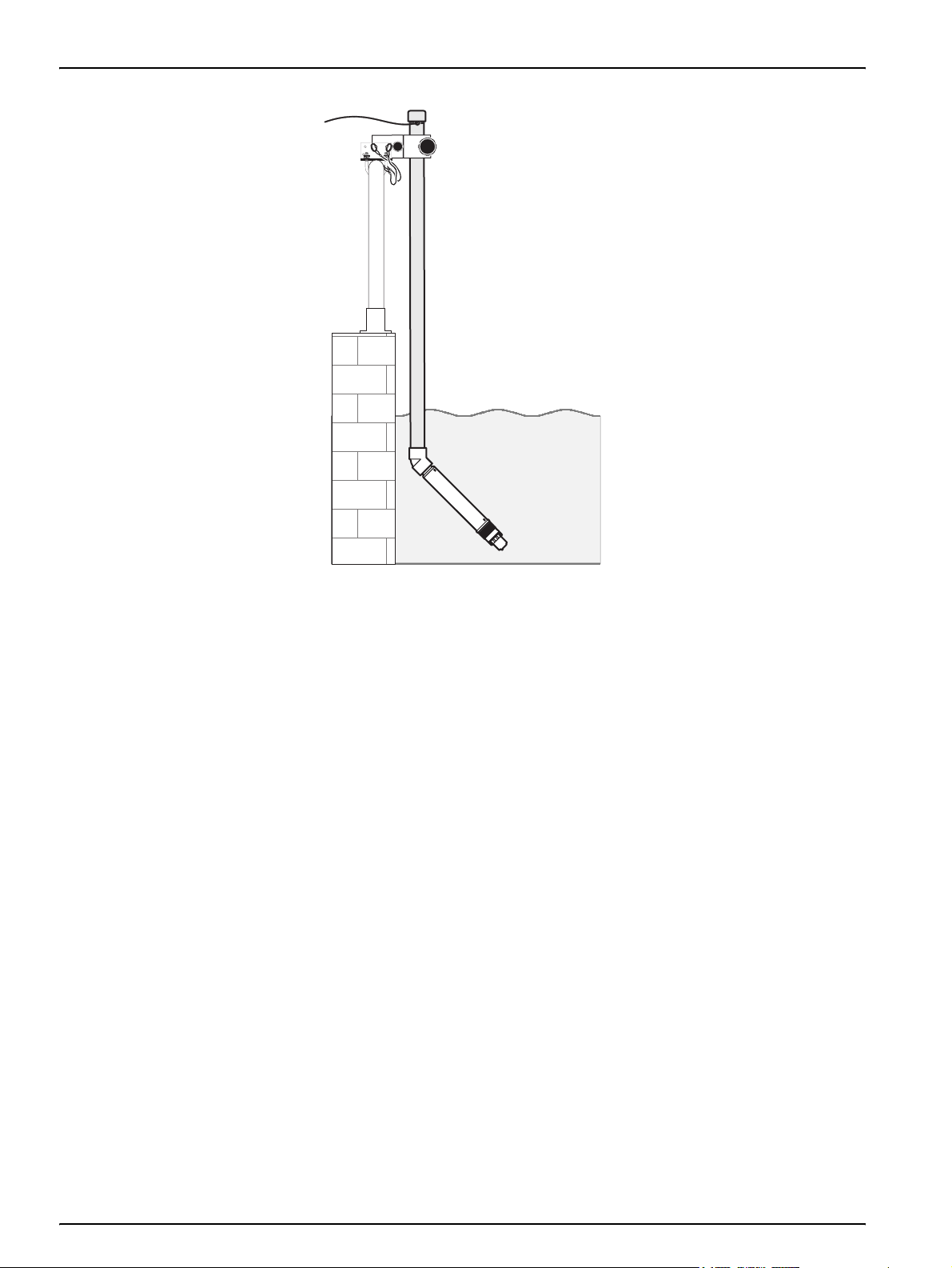
3.5 Installation of the sensor in the sample flow
Installation kits are available for the installation of the sensor with or
without a cleaning unit for a wide range of requirements.
The following rules must always be considered prior to installation:
• Install the sensor where the sample that comes into contact
with the sensor is representative of the entire process.
• Position the sensor at least 200 mm (7.87 in.) from the tank
wall.
• When using a chain bracket, ensure that the sensor cannot hit
the tank wall when it moves.
• Immerse the sensor at an angle of approx. 45° ± 15° in the
direction of the flow so that air bubbles cannot remain
underneath the membranes.
• Ensure that the sensor is fully immersed.
• When using the cleaning unit refer to the supplied Instruction
Sheet.
• Refer to the instructions supplied with the optional mounting
accessories for detailed installation information (see Figure 10
on page 16).
15
Page 16
Installation
Figure 10 Example of sensor installation with Rail Mount Kit
16
Page 17

Installation
3.6 Connect the sensor to the sc controller (non-hazardous location) with quick-connect fittings
The sensor cable is supplied with a keyed quick-connect fitting for
easy attachment to the controller (see Figure 11 on page 17).
Retain the connector cap to seal the connector opening in case the
sensor must be removed. Optional extension cables may be
purchased to extend the sensor cable length.
1. Unscrew the protective cap from the socket on the controller.
2. Insert the connector in the socket and hand-tighten the union
nut.
Note: When using an sc1000 controller, do not use the middle connection
for the sensors as this is reserved for the display module.
Figure 11 Connect the sensor using quick-connect fitting on the sc controller
17
Page 18

Installation
18
Page 19

Section 4 Operation
4.1 Using an sc controller
4.2 Sensor setup
Before using the sensor in combination with an sc controller, refer
to the controller user manual for navigation information.
When a sensor is installed for the first time, the serial number of the
sensor is displayed as the sensor name. The sensor name can be
changed as follows:
1. Select
2. From the Main Menu, select
3. Select the appropriate sensor if more than one sensor is
attached and confirm.
4. Select
5. Select
return to the Sensor Setup menu.
4.3 Sensor data logging
The sc controller provides a data log and an event log for each
sensor. The data log contains the measured data at selected
intervals. The event log contains a large number of events that
occur on the instruments, such as configuration changes, alarms
and warnings, etc. The data log and the event log can be exported
to CSV format. For information on downloading the logs, refer to the
sc controller user manual.
4.4 Sensor diagnostics menu
SELECT SENSOR
ERROR LIST Displays all actual error codes.
MAIN MENU.
SENSOR SETUP and confirm.
CONFIGURE and confirm.
EDIT NAME and edit the name. Confirm or cancel to
WARNING LIST Displays all actual warnings.
19
Page 20

Operation
4.5 Sensor setup menu
SELECT SENSOR (if there is more than one sensor)
CALIBRATE
Note: If once a calibration method is chosen the entries will be displayed in the first
submenu of the calibrate menu.
CAL.CONFIG.
Select SENSOR CODE, MATX1, MATX1 CL-, MATX2, MATX2 CL-, VALUE CORR,
PREVIOUS CAL or FACTORY CAL
-or-
CAL.CONFIG.>SENSOR CODE
DATE Displays the date of sensor cartridge start up
SENSOR CODE Display and entry of the sensor code
-orCAL.CONFIG.>MATX1 1 point matrix correction (see section 4.6.3.1 on page 24)
DATE Displays the date of the current correction
CONC MEAS 1 Saving the currently measured measurement
SET NO3–N CONC Entry and display of the NO
-orCAL.CONFIG.>MATX1 CL- 1 point matrix correction with chloride (see section 4.6.3.2 on page 24)
DATE Displays the date of the current correction
CONC MEAS 1 Saving the currently measured measurement
SET CL- CONC Entry and display of the Cl
SET NO3–N CONC Entry and display of the NO
-orCAL.CONFIG.>MATX2 2 point matrix correction (see section 4.6.3.3 on page 25)
CONC MEAS 1 Saving the currently measured measurement
DATE Displays the date of the current correction
SET NO3–N CONC Entry and display of the NO
CONC MEAS 2 Saving the second measured measurement
DATE Displays the date of the current correction
SET NO3–N CONC Entry and display of the NO
-or-
CAL.CONFIG.>MATX2 CL-
2 point matrix correction with chloride (see section 4.6.3.4 on page 26)
Note: Carry out the matrix correction only as a standard addition in the sample matrix.
CONC MEAS 1 Saving the currently measured measurement
DATE Displays the date of the current correction
SET CL- CONC Entry and display of the Cl
SET NO3–N CONC Entry and display of the NO
CONC MEAS 2 Saving the second measured measurement
DATE Displays the date of the current correction
SET CL- CONC Entry and display of the Cl
SET NO3–N CONC Entry and display of the NO
–N reference value (lab value)
3
-
reference value (lab value)
–N reference value (lab value)
3
–N reference value (lab value)
3
–N reference value (lab value)
3
-
reference value (lab value)
–N reference value (lab value)
3
-
reference value (lab value)
–N reference value (lab value)
3
20
Page 21

4.5 Sensor setup menu (continued)
CALIBRATE(continued)
Value correction (see section 4.6.3.5 on page 27)
Once value correction is complete, the correction data are displayed in the form of
the MATX2
1st NO3–N NO3DSC
1st CL- NO3DSC
CAL.CONFIG.>
VALUE CORR
1st NO3–N LAB
2nd NO3–N NO3DSC
2nd CL- NO3DSC
2nd NO3–N LAB
-orCAL.CONFIG.>
PREVIOUS CAL
Selection of one of the last four matrix and value corrections performed
-orCAL.CONFIG.>
FACTORY CAL
Selection of the preset sensor code
DATE Date of last calibration
SENSOR CODE Enter the sensor code
CONFIGURE
EDIT NAME Entry or editing of the name. Up to 10 alphanumeric characters.
MEAS UNITS Selection of mg/L or ppm as measurement unit
SET PARAMETER Selection of NO
–N or NO
3
3
TEMP UNITS Selection of °C or °F as temperature unit.
TEMP CORR Entry of the temperature correction (–1.5 to +1.5 °C or –2.7 to +2.7 °F)
RESPONSE TIME Entry of the response time (30 sec to 300 sec)
LOG SETUP
Selects the interval for the data logging
(deactivate, 1, 2, 5, 10, 15, 30 min, 1, 2, 6 hr).
CL- COMPENSATE. Selection of the chloride compensation: On, off or fixed value
SET DEFAULTS Resets the configuration on the factory setting.
Enter the NO3–N concentration (NO3D sc) of
the 1st point
-
Enter the Cl
concentration (NO3D sc) of the
1st point
Enter the NO
–N concentration (lab) of the 1st
3
point
Enter the NO
–N concentration (NO3D sc) of
3
the second point
-
Enter the Cl
concentration (NO3D sc) of the
second point
Enter the NO
–N concentration (lab) of the
3
second point
Operation
21
Page 22

Operation
4.5 Sensor setup menu (continued)
DIAG/TEST
Information on the connected sensor
PROBE INFO
CAL DATA Data of the selected MATRIX correction
SIGNALS
COUNTERS
SERVICE Performing a sensor check using TEST CARTRIDGE (see 7.2 on page 37)
EDIT NAME Name of the connected sensor
SERIAL NUMBER Serial number of the connected sensor
SOFTWARE VERS Software version
Signals and measurements of the individual measurement channels
NITRATE Displays the signals and measurement results
CHLORIDE Displays the signals and measurement results
TEMP Displays the temperature
Sensor code (time the sensor code was entered generally corresponds with the age of the
cartridge) and CAL. days
4.6 Calibration
The membranes on the ion-selective electrodes are not 100%
selective due to other substances that may affect the
measurement. Perform a matrix correction to compensate the
influences of other ions on the nitrate ISE electrode.
4.6.1 Sensor code calibration
Chloride has the largest interference effect on the nitrate
membrane. This problem is compensated in the NO3D sc sensor
using the integrated chloride electrode.
CARTRICAL
TM
is a compact sensor cartridge with 3 electrodes,
which are perfectly factory calibrated to each other.
Cross sensitivities between nitrate and chloride are automatically
eliminated. Solids do not interfere with the measurement. Due to
matrix effects calibration and validation can not be performed with
standard solutions. A matrix correction can be carried out quickly
and easily at any time.
Important Note: Matrix correction must not be performed until the
sensor has been immersed in the process longer than 12 hours.
12 hours is the mimimum amount of time required for the ISE
membranes to adapt to the waste water matrix.
The 12 hours is required to allow the sensor cartridge to adapt to
the process.
When activating a new sensor cartridge or during initial calibration,
the sensor code must be entered. The default sensor code is
IIIIIIIIIIIIIIII (all 16 I capital letters are the same). With this code, the
sensor is ready for operation. To meet published specifications,
enter the individual sensor code for the specific CARTRICAL
cartridge.
22
Enter the sensor cartridge's sensor code to accept the CARTRICAL
calibration. The sensor code is a 16 character code (letters and
numbers) and will be supplied with the sensor cartridge certificate.
The code contains the factory calibration for the sensor cartridge,
Page 23

Operation
which includes a multi-point nitrate and chloride calibration and the
cross sensitivity of chloride on nitrate.
When the code is entered, the sensor is completely calibrated. It is
recommended to perform a matrix correction to correct the
cartridge on the specific matrix.
Please use the default sensor code, if the specific sensor code is
not available.
To change the sensor code:
4.6.2 Matrix correction overview
Table 1 Correction options for the NO3D sc sensor
1. Select
CALIBRATE>CAL.CONFIG.>SENSORCODE
SENSOR SETUP>NO3D SC>
2. Enter the 16 character sensor code.
3. Press
ENTER to confirm and activate the sensor code.
The day meter is set to zero.
All old calibration data are now overwritten with the new calibration
data from the sensor code. The sensor code data are checked by
the system. If an error is indicated, check the sensor code and
repeat the entry of the sensor code if necessary.
With the NO3D sc sensor, there are various options (Table 1) for
correcting the measured value with laboratory reference values.
For the laboratory reference value, a sample is taken for laboratory
analysis and the measurement value at that time is stored.
Depending on the parameter set, the laboratory reference value of
the water sample is stored as nitrate nitrogen (NO
(NO
). This laboratory reference value replaces the prior value
3
–N) or as nitrate
3
measured by the sensor.
Correction Option Application
MATX1
MATX1 CL-
MATX2
MATX2 CL-
VALUE CORR
PREVIOUS CAL Activation of one of the last 4 matrix and value corrections performed.
FACTORY CAL
1
Examples of a half decade: The nitrate nitrogen concentration moves between 1 and 5 mg NO3–N or
between 5 and 25 mg/L NO
The most commonly used Matrix correction. It performs a 1 point matrix correction (offset
adjustment) for nitrate (4.6.3.1 on page 24).
With the MATX1 CL- the nitrate value will be corrected as with the MATX1 and in addition the
chloride value can be corrected. This is necessary if a higher precision of the nitrate value is required
as the chloride value will interfere with the nitrate measurement (4.6.3.2 on page 24).
Where there is a dynamic process with a large nitrate fluctuation (at least 1/2 decade between the
lowest and highest concentration)
Where there is a dynamic process with a large nitrate fluctuation (at least 1/2 decade between the
lowest and highest concentration)
perform the MATX2 CL- (4.6.3.4 on page 26).
The nitrate and chloride displayed value and the nitrate laboratory value can be entered for two
points. This is a different way to perform a MATX2 Correction. Here, for two points, the displayed
nitrate and chloride values and the nitrate laboratory value are entered via an input screen.
If the current sensor code is no longer available, average data for the sensor can be activated using
FACTORY CAL.
–N ( Conc 2 = (Conc 1 x 10)/2 ).
3
1
, it is recommended to perform the MATX2 (4.6.3.3 on page 25).
1
and chloride value is to be corrected, it is recommended to
23
Page 24

Operation
4.6.3 Matrix correction
Note: Perform laboratory values or comparative values with cuvette tests
timely or stabilized the sample, to avoide a modification of the sample
concentration.
In 7.3 Validation accessories on page 37 you can find
recommended tests which can be used for laboratory
measurements.
Note: Laboratory comparison or verification samples are time sensitive.
Perform analysis of these samples as quickly as possible to minimize the
potential for a bias or interference in the results.
4.6.3.1 MATX1 correction (one point matrix correction)
Proceed as follows to perform the MATX1:
CALIBRATE
CAL. CONFIG.
DATE
CONC MEAS 1
SET NO3–N CONC
READING STABLE?
NO3–N:
DRIFT
CLDRIFT
1. Select
2. Select
3. Select
SENSOR SETUP>NO3D SC>CALIBRATE> CAL CONFIG.
MATX1 in the selection window and press ENTER.
CONC MEAS 1.
The currently measured nitrate and chloride values are displayed.
The drift indicates whether the measured value is stable.
4. Wait until the measured value is stable and confirm by pressing
ENTER (Drift should be < 0.03 mg/L). The values for nitrate and
chloride are saved.
5. Immediately after saving, take a water sample for laboratory
analysis from as close to the sensor as possible.
6. Analyze the sample immediately after taking the sample as its
nitrate content can change quickly.
After determining the laboratory reference value, proceed as
follows:
7. Select
SET NO3–N CONC
SENSOR SETUP>NO3D SC>CALIBRATE>
.
4.6.3.2 MATX1 CL- correction
CALIBRATE
CAL. CONFIG.
DATE
CONC MEAS 1
SET CL- CONC
SET NO3–N CONC
24
8. Enter the laboratory value (reference value) for NO
press
ENTER to confirm. Confirmation of the entered laboratory
value activates the matrix correction.
Proceed as follows to perform the MATX1 CL-:
1. Select
2. Select
3. Select
SENSOR SETUP>NO3D SC>CALIBRATE> CAL CONFIG.
MATX1 CL- in the selection window and press ENTER.
CONC MEAS 1.
–N and
3
Page 25

Operation
READING STABLE?
NO3–N:
DRIFT
CLDRIFT
The currently measured nitrate and chloride values are displayed.
The drift indicates whether the measured value is stable.
4. Wait until the measured value is stable and confirm by pressing
ENTER (Drift should be < 0.03 mg/L). The values for nitrate and
chloride are saved.
5. Immediately after saving, take a water sample for laboratory
analysis from as close to the sensor as possible.
6. Analyze the sample immediately after taking the sample as its
nitrate content can change quickly.
After determining the laboratory reference values for chloride and
nitrate, proceed as follows:
7. Select
SET NO3–N CONC
8. Enter the laboratory reference value for NO
ENTER to confirm.
9. Select
SET CL- CONC
SENSOR SETUP>NO3D SC>CALIBRATE>
.
–N and press
3
SENSOR SETUP>NO3D SC>CALIBRATE>
.
10. Enter the laboratory reference value for chloride and press
ENTER to confirm.
Confirmation of the entered laboratory value activates the
matrix correction.
4.6.3.3 MATX2 correction (2nd point matrix correction)
Proceed as follows to perform the MATX2:
CALIBRATE
CAL. CONFIG.
CONC MEAS 1
DATE
SET NO3–N CONC
CONC MEAS 2
DATE
SET NO3–N CONC
READING STABLE?
NO3–N:
DRIFT
CLDRIFT
1. Select
2. Select
3. Select
The currently measured nitrate and chloride values are displayed.
The drift indicates whether the measured value is stable.
4. Wait until the measured value is stable (Drift should be
< 0.03 mg/L) and press
is saved.
5. Immediately after measuring, take a water sample for
laboratory analysis from as close to the sensor as possible.
SENSOR SETUP>NO3D SC>CALIBRATE>CAL CONFIG.
MATX2 in the selection window and press ENTER.
CONC MEAS 1.
ENTER to confirm. The value for nitrate
6. Analyze the sample immediately after taking the sample as its
nitrate content can change quickly.
25
Page 26

Operation
After determining the laboratory reference value, proceed as
follows:
4.6.3.4 MATX2 CL- correction
CALIBRATE
CAL. CONFIG.
CONC MEAS 1
DATE
SET CL- CONC
SET NO3–N CONC
CONC MEAS 2
DATE
SET CL- CONC
SET NO3–N CONC
7. Select
SET NO3–N CONC
8. Enter the laboratory value (reference value) for NO
press
9. Select
SENSOR SETUP>NO3D SC>CALIBRATE>
.
–N and
ENTER to confirm.
MEAS CONC 2 and repeat the sequence from Point 4 to
3
8 for the second value after a concentration change of at least
half a decade.
10. By confirming the second laboratory value, the Matrix2
correction is activated.
Select MATX2 CL- to calibrate the nitrate and chloride sensor
simultaneously at two different measuring points.
1. Select
2. Select
3. Select
SENSOR SETUP>NO3D SC>CALIBRATE> CAL CONFIG.
MATX2 CL- in the selection window and press ENTER.
CONC MEAS 1 and wait until the NO
–N and Cl- values
3
are stable (drift should be <0.03 mg/L).
4. Press
ENTER to confirm. The value for nitrate and chloride are
saved.
5. Immediately after measuring, take a water sample for
laboratory analysis from as close to the sensor as possible.
6. Analyze the sample immediately after taking the sample as its
nitrate content can change quickly.
After determining the laboratory reference value, proceed as
follows:
1. Select
CONC
2. Enter the laboratory value (reference value) for NO
press
3. Select
CONC 1
SENSOR SETUP>NO3D SC>CALIBRATE>SET NO3-N
.
-N and Cl-
ENTER to confirm.
MEAS CONC 2 and repeat the sequence from MEAS
3
for the second value after a concentration change of at
least half a decade.
4. By confirming the second laboratory value, the Matrix2
correction is activated.
26
Page 27

4.6.3.5 Value correction
Operation
Value correction offers the option of subsequently correcting a
matrix at two different concentrations.
Take several samples on various days with different concentrations
and perform an analysis of the samples in the laboratory.
Note: The concentrations should be in a concentration range of at least
half a decade.
Conc1 10×
Conc2
1. Note the two displayed nitrate and chloride values, which are
measured with the sensor at the time of the sampling.
2. Then note the measured nitrate laboratory reference value.
All 3 values are one correction point.
3. From the values recorded, select the two correction points with
nitrate concentrations as far apart as possible.
-------------------------------
=
2
4. Select
and press
CAL CONFIG.> CALIBRATE>VALUE CORR from the menu
ENTER to confirm.
Enter the 3 noted values:
5. 1. NO3–N NO3D sc: Enter the displayed NO
1st correction point. Press
6. 1. CL- NO3D sc: Enter the displayed Cl
correction point. Press
7. 1. NO3–N lab: Enter the measured NO
ENTER to confirm.
ENTER to confirm.
3
−
value for the 1st
–N laboratory
reference value for the 1st correction point. Press
confirm.
8. 2. NO3–N NO3D sc: Enter the displayed NO
2nd correction point. Press
9. 2. CL- NO3D sc: Enter the displayed Cl
correction point. Press
10. 2. NO3–N lab: Enter the measured NO
ENTER to confirm.
ENTER to confirm.
3
-
value for the 2nd
–N laboratory
reference value for the 2nd correction point. Press
confirm.
Value correction is activated and displayed as
–N value for the
3
ENTER to
–N value for the
3
ENTER to
MATX2.
27
Page 28

Operation
28
Page 29

Section 5 Maintenance
Important Note: Only qualified personnel should conduct the tasks
described in this section of the manual.
5.1 Maintenance schedule
Maintenance task 30 days
2
Clean sensor
Replace the sensor cartridge
Check sensor for damage x
Check measured value by lab reference analysis and correct values by matrix
correction if required
1
Recommendation: weekly during the first month in operation
2
The frequency of cleaning depends on the application. In some applications more or less frequent cleaning may be necessary.
3
In typical operating conditions, a different interval may be required depending on the specific application and local conditions.
4
Sensor cartridges are wear parts and are not covered by the instrument warranty.
x
3, 4
3
1
x
6 months
x
Important Note: Do not check the sensor with usual NO3–N standard solutions, because the ion strength of
normal standard solutions are not strong enough. Use therefore calibration solutions with artificial ion matrix
generate to have plausible measurements.
5.2 Clean the sensor
Important Note:
Do not touch the membranes with fingers.
Do not clean the sensor cartridge with sharp objects that may
cause scratches and do not use any chemical cleaning agent.
5.2.1 Polish the chloride electrode
1. Clean the sensor cartridge with the soft brush supplied.
2. Clean the sensor body (not the cartridge) with a sponge or
brush.
3. Rinse the sensor with clean, lukewarm tap water.
Polish the chloride electrode if it shows signs of being heavily
coated/contaminated. If the electrode slope sinks below
40 mV/Dec. following a 2-point matrix calibration, clean the chloride
electrode with the polishing paper supplied. To do this, lightly
moisten the polishing paper and then carefully and evenly polish
the coating away.
Important Note: Only the LZY671 polishing paper supplied may be
used!
29
Page 30

Maintenance
Figure 12 Chloride electrode
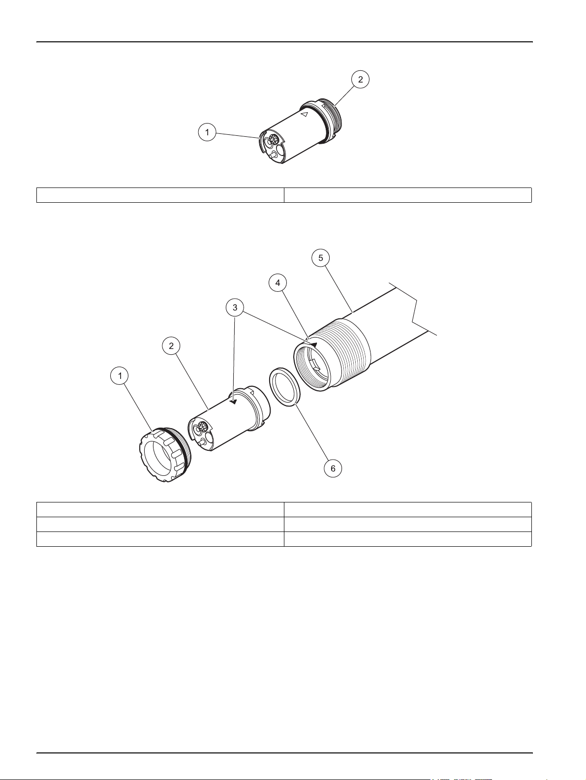
5.3 Replace the sensor cartridge
The sensor cartridge is replaced as described below and in
Figure 13 on page 31.
1. Clean the sensor and thoroughly dry the sensor cartridge and
the sensor adapter.
2. Unscrew the locking ring and remove.
Important Note: The sensor cartridge must direct downwards so
that no water can run into the sensor adapter. The contacts
between the sensor and the sensor cartridge must remain dry.
3. Pull the sensor cartridge out of the sensor adapter and dispose
of the old sensor cartridge and opaque gasket per applicable
regulations.
4. Ensure that the new opaque gasket is installed during every
sensor cartridge replacement.
5. Insert the new sensor cartridge in the sensor adapter. Pay
attention to the triangular marking on the cartridge and on the
sensor.
Important Note: The sensor cartridge only fits correctly in the
sensor adapter in one position. Pay attention to the markings on the
sensor cartridge and on the sensor adapter.
6. Attach the locking ring over the sensor head and hand-tighten.
Note: Use the cap of the storage container as a tool/screwing aid for
the locking ring.
30
7. Enter the new sensor code (see certificate).
Page 31

Figure 13 Replace the sensor cartridge
1 Locking ring 4 Sensor adapter
2 Sensor cartridge 5 Sensor housing
3 Markings 6 Opaque gasket
Maintenance
31
Page 32

Maintenance
5.4 Storage
Remove the sensor from the sample flow and clean the sensor
thoroughly.
Short term storage
Keep the membranes and the salt bridge moist by using drinking
water or shipping boot solution (NO DISTILLED WATER OR
DI WATER). This will help avoid long response times when placing
the sensor back in the sample flow. Otherwise, the correct
operation of the sensor is no longer guaranteed.
Long term storage
Important Note: Use the delivered storage container for long term
storage. Fill the container with drinking water or use the shipping
boot solution (NO DISTILLED WATER) and ensure that the sensor
cartridge remains wet.
Check the membranes and ensure they are still moist every
2–4 weeks, depending on environmental conditions.
Note: A storage container is supplied to keep the sensor cartridge moist.
Keep sensor cartridge capped within the storage container during short
and long term storage. Refer to Section 1 Specifications on page 5 for
storage temperatures.
Note: The black gasket is needed for sealing function. See Figure 6 on
page 13.
Sensor and sensor cartridge
Note: Take care of contacts between sensor and sensor cartridge. The
contacts must be dry. Store in a dry place.
32
Page 33

Section 6 Troubleshooting
6.1 Error codes
When the sensor is experiencing an error condition, the sensor
reading on the measurement screen will flash and the relays and
analog outputs associated with this sensor will be held or
transferred to a previously defined state depending on the
configuration settings used in the controller. Errors are defined in
Table 2.
Tab le 2 Erro r codes
Displayed errors Definition Resolution
NO3 mV RANGE! Nitrate mV value is out of measuring range
CL- mV RANGE! Chloride mV value is out of measuring range
pHD RANGE! pHD reference value out of measuring range
TEMP RANGE Temperature value out of measuring range
NO CARTRIDGE No sensor cartridge connected
SENSOR CODE Sensor code calibration failed
See 6.3.1 Troubleshooting during operation on
page 34.
Connect sensor cartridge, see section 3.3 on
page 13.
See 6.3.2 Troubleshooting during calibration on
page 36
6.2 Warning codes
A sensor warning will leave all menus, relays and outputs functioning
normally, but will cause a warning icon to flash
Warnings may be used to trigger a relay and users can set warning
levels to define the severity. Warnings are defined in Table 3.
Table 3 Warning codes
Displayed warnings Definition Resolution
NO3 mV RANGE! Nitrate mV value is close to measuring range limit
CL- mV RANGE!
pHD RANGE! pHD reference value is close to limit
TEMPERATURE Temperature is close to limit
CARTRIDGE OLD Sensor cartridge more than 1 year old Replace the sensor cartridge
NITRATE
OFFSET Nitrate offset is out of measuring range
SLOPE Nitrate slope is out of measuring range
CHLORIDE
OFFSET Chloride offset is out of measuring range
SLOPE Chloride slope is out of measuring range
Chloride mV value is close to measuring range
limit
See 6.3.1 Troubleshooting during operation
on page 34.
See 6.3.2 Troubleshooting during calibration
on page 36.
.
33
Page 34

Troubleshooting
6.3 Troubleshooting
6.3.1 Troubleshooting during operation
Symptom Possible cause Corrective actions
Incorrect measurement
values
Calibration too old; calibration was not suitable for
the particular case; big change in the waste water
matrix
Strongly contaminated membranes and/or
reference electrode
Sensor membrane damaged
Reference element damaged
NO3 mV RANGE! (Nitrate mV value is out of
measuring range)
CL- mV RANGE! (Chloride mV value is out of
measuring range)
pHD RANGE! (pHD reference value is out of
range)
TEMPERATURE (temperature value is out of
range)
CARTRIDGE OLD (cartridge more than 1 year
old)
Dampness at the contacts of the sensor cartridge
Carry out suitable calibration
See 4.6 Calibration on page 22
Clean the sensor cartridge using a brush
and/or rinse the sensor cartridge with clean
water (without cleaning agents), and wipe the
sensor cartridge carefully with a soft, clean
cloth.
Clean all components (membranes/reference
electrode/temperature sensor).
Install cleaning unit
Increase cleaning interval
Check sensor installation/replace sensor
cartridge
Check sensor installation/replace sensor
cartridge
Replace sensor cartridge
Replace sensor cartridge
Replace sensor cartridge
Replace sensor cartridge/check waste water
temperature
Replace sensor cartridge
Dry the contacts with a cloth or some paper.
Check the opaque gasket for damage and
the correct position.
Screw the locking ring on.
Note: Use the cap of the storage container as
a tool/screwing aid for the locking ring
(Figure 9 on page 15).
34
Page 35

6.3.1 Troubleshooting during operation (continued)
Symptom Possible cause Corrective actions
Dampness inside the measuring probe/faulty
sensor electronics
Check the sensor electronics by using the test
cartridge (section 7.2 on page 37).
1 Select
SENSOR-SETUP>DIAG/TEST>SERVICE>
TEST CARTRIDGE>Test cartridge
Ready? Press ENTER
2 Compare the displayed values with the guide
values. The displayed values should be in the
same range as the guide values below. Wait
for stabilization before pressing ENTER:
NITRATE:
SIGNAL –237.0<(–226.2 mV)<–217.0
Incorrect measurement
values
MESS 2263.6<(2274,4 mV)<2283.6
REF 2450.6<(2500.6 mV)<2550.6
ENTER
CHLORIDE:
SIGNAL –10.0<(–2.9 mV)<10.0
MESS 2490.6<(2497.7 mV)<2510.6
REF 2450.6<(2500.6 mV)<2550.6
ENTER
Troubleshooting
If the test cartridge data are not within this
range or if the test cartridge check is not
successful, contact our service or technical
support department.
Unstable measurement
values
TEMPERATURE VALUES:
TEMP 24.5<(24.8 ºC)<25.5/
76.1<(76.6ºF)<77.9
ENTER
3 If the test cartridge data are within range, the
sensor electronics are functional:
Test cartridge
OK
ENTER
Air bubbles, depth of immersion
Dampness at the contacts of the sensor cartridge
Sensor membrane damaged Check installation/replace sensor cartridge
Reference element damaged Check installation/replace sensor cartridge
Airbubbles underneath the membrane
Check the installation
Check the configuration of the cleaning unit
Dry the contacts with a cloth or some paper.
Check the opaque gasket for damage and
the correct position of the gasket.
Screw the locking ring on.
Note: Use the cap of the storage container as
a tool/screwing aid for the locking ring.
Hold sensor cartridge in hand with
membranes facing straight down and shake
gently in a downward motion two times to
remove air bubbles that may form
underneath the membrane.
35
Page 36

Troubleshooting
6.3.2 Troubleshooting during calibration
Symptom Possible cause Corrective actions
SENSOR CODE Sensor code entered incorrectly
NITRATE
OFFSET
SLOPE
CHLORIDE
OFFSET
SLOPE
Error in the last nitrate calibration, sensor
cartridge too old, contaminated, faulty
Error in the last nitrate calibration, sensor
cartridge too old, contaminated, faulty
Error in the last chloride calibration, sensor
cartridge too old, contaminated, faulty
Error in the last chloride calibration, sensor
cartridge too old, contaminated, faulty
Using the certificate, check whether the
sensor code was entered correctly. If not
having the certificate, carry out "Factory
Calibration" (Factory cal).
Repeat the calibration.
Use the previous calibration.
Clean or replace the sensor cartridge.
Repeat the calibration.
Use the previous calibration.
Clean or replace the sensor cartridge.
Repeat the calibration.
Use the previous calibration.
Clean or replace the sensor cartridge.
Repeat the calibration.
Use the previous calibration.
Clean or replace the sensor cartridge.
36
Page 37

Section 7 Spare Parts and Accessories
7.1 Spare parts
Description Catalog Number
NO3D sc (sensor with 10 m (32.8 ft.) integral cable and one pre-calibrated Sensor Cartridge) LXV442.99.00002
Calibrated Sensor Cartridge
Cleaning brush LZY589
Locking ring kit 6176900
Opaque gasket HZD176
Cable clip for NO3Dsc LZY698
1
Sensor cartridges are wearing parts that are not covered by the instrument warranty.
1
7.2 Accessories
Description Catalog Number
Cleaning Unit LZY331
Rail Mount Kit 6184900
Chain Mount Kit LZX914.99.12400
Stainless Steel Basin Edge Mounting LZX414.00.80000
High Output Air Blast compressor 115 V/50 Hz 6860003
High Output Air Blast compressor 230 V/50 Hz 6860103
Test cartridge 6188300
Polishing paper for the chloride electrode LZY671
6188401
7.3 Validation accessories
Description Catalog Number
Quantab chloride test sticks 33 to 649 mg/L Cl for US 27449-40
Test‘N Tube Vials 0.2 to 30 mg/L NO
-N 2605345
3
.
7.4 Corresponding documentation
Description Catalog Number
Instruction sheet Cleaning Unit DOC306.53.00747
Instruction sheet Rail Mounting DOC306.53.00145
Instruction sheet Chain Mounting DOC306.53.00147
Manual HOAB compressor DOC026.53.00811
Manual sc100 5860018
Manual sc1000 DOC023.53.90007
37
Page 38

Spare Parts and Accessories
38
Page 39

Section 8 Contact information
HACH Company
World Headquarters
P.O. Box 389
Loveland, Colorado
80539-0389 U.S.A.
Tel (800) 227-HACH
(800) -227-4224
(U.S.A. only)
Fax (970) 669-2932
orders@hach.com
www.hach.com
HACH LANGE GMBH
Willstätterstraße 11
D-40549 Düsseldorf
Tel. +49 (0)2 11 52 88-320
Fax +49 (0)2 11 52 88-210
info@hach-lange.de
www.hach-lange.de
DR. BRUNO LANGE AG
Juchstrasse 1
CH-8604 Hegnau
Tel. +41(0)44 9 45 66 10
Fax +41(0)44 9 45 66 76
info@hach-lange.ch
www.hach-lange.ch
Repair Service in the
United States:
HACH Company
Ames Service
100 Dayton Avenue
Ames, Iowa 50010
Tel (800) 227-4224
(U.S.A. only)
Fax (515) 232-3835
HACH LANGE LTD
Pacific Way
Salford
GB-Manchester, M50 1DL
Tel. +44 (0)161 872 14 87
Fax +44 (0)161 848 73 24
info@hach-lange.co.uk
www.hach-lange.co.uk
HACH LANGE FRANCE
S.A.S.
33, Rue du Ballon
F-93165 Noisy Le Grand
Tél. +33 (0)1 48 15 68 70
Fax +33 (0)1 48 15 80 00
info@hach-lange.fr
www.hach-lange.fr
Repair Service in Canada:
Hach Sales & Service
Canada Ltd.
1313 Border Street, Unit 34
Winnipeg, Manitoba
R3H 0X4
Tel (800) 665-7635
(Canada only)
Tel (204) 632-5598
Fax (204) 694-5134
canada@hach.com
HACH LANGE LTD
Unit 1, Chestnut Road
Western Industrial Estate
IRL-Dublin 12
Tel. +353(0)1 46 02 5 22
Fax +353(0)1 4 50 93 37
info@hach-lange.ie
www.hach-lange.ie
HACH LANGE SA
Motstraat 54
B-2800 Mechelen
Tél. +32 (0)15 42 35 00
Fax +32 (0)15 41 61 20
info@hach-lange.be
www.hach-lange.be
Repair Service in
Latin America, the
Caribbean, the Far East,
Indian Subcontinent, Africa,
Europe, or the Middle East:
Hach Company World
Headquarters,
P.O. Box 389
Loveland, Colorado,
80539-0389 U.S.A.
Tel +001 (970) 669-3050
Fax +001 (970) 669-2932
intl@hach.com
HACH LANGE GMBH
Hütteldorferstr. 299/Top 6
A-1140 Wien
Tel. +43 (0)1 9 12 16 92
Fax +43 (0)1 9 12 16 92-99
info@hach-lange.at
www.hach-lange.at
DR. LANGE NEDERLAND
B.V.
Laan van Westroijen 2a
NL-4003 AZ Tiel
Tel. +31(0)344 63 11 30
Fax +31(0)344 63 11 50
info@hach-lange.nl
www.hach-lange.nl
HACH LANGE APS
Åkandevej 21
DK-2700 Brønshøj
Tel. +45 36 77 29 11
Fax +45 36 77 49 11
info@hach-lange.dk
www.hach-lange.dk
HACH LANGE LDA
Av. do Forte nº8
Fracção M
P-2790-072 Carnaxide
Tel. +351 214 253 420
Fax +351 214 253 429
info@hach-lange.pt
www.hach-lange.pt
HACH LANGE KFT.
Vöröskereszt utca. 8-10.
H-1222 Budapest XXII. ker.
Tel. +36 (06)1 225 7783
Fax +36 (06)1 225 7784
info@hach-lange.hu
www.hach-lange.hu
HACH LANGE AB
Vinthundsvägen 159A
SE-128 62 Sköndal
Tel. +46 (0)8 7 98 05 00
Fax +46 (0)8 7 98 05 30
info@hach-lange.se
www.hach-lange.se
HACH LANGE SP.ZO.O.
ul. Opolska 143 a
PL-52-013 Wrocław
Tel. +48 (0)71 342 10-83
Fax +48 (0)71 342 10-79
info@hach-lange.pl
www.hach-lange.pl
HACH LANGE S.R.L.
Str. Căminului nr. 3
Sector 2
RO-021741 Bucureşti
Tel. +40 (0) 21 205 30 03
Fax +40 (0) 21 205 30 17
info@hach-lange.ro
www.hach-lange.ro
HACH LANGE S.R.L.
Via Riccione, 14
I-20156 Milano
Tel. +39 02 39 23 14-1
Fax +39 02 39 23 14-39
info@hach-lange.it
www.hach-lange.it
HACH LANGE S.R.O.
Lešanská 2a/1176
CZ-141 00 Praha 4
Tel. +420 272 12 45 45
Fax +420 272 12 45 46
info@hach-lange.cz
www.hach-lange.cz
HACH LANGE
8, Kr. Sarafov str.
BG-1164 Sofia
Tel. +359 (0)2 963 44 54
Fax +359 (0)2 866 15 26
info@hach-lange.bg
www.hach-lange.bg
HACH LANGE S.L.U.
Edif. Arteaga Centrum
C/Larrauri, 1C- 2ª Pl.
E-48160 Derio/Vizcaya
Tel. +34 94 657 33 88
Fax +34 94 657 33 97
info@hach-lange.es
www.hach-lange.es
HACH LANGE S.R.O.
Roľnícka 21
SK-831 07 Bratislava –
Vaj nory
Tel. +421 (0)2 4820 9091
Fax +421 (0)2 4820 9093
info@hach-lange.sk
www.hach-lange.sk
HACH LANGE SU
ANALİZ SİSTEMLERİ
LTD. ŞTİ.
Hilal Mah. 75. Sokak
Arman Plaza No: 9/A
TR-06550 Çankaya/ANKARA
Tel. +90 (0)312 440 98 98
Fax +90 (0)312 442 11 01
bilgi@hach-lange.com.tr
www.hach-lange.com.tr
HACH LANGE D.O.O.
Fajfarjeva 15
SI-1230 Domžale
Tel. +386 (0)59 051 000
Fax +386 (0)59 051 010
info@hach-lange.si
www.hach-lange.si
ΗΑCH LANGE E.Π.Ε.
Αυλίδος 27
GR-115 27 Αθήνα
Τηλ. +30 210 7777038
Fax +30 210 7777976
info@hach-lange.gr
www.hach-lange.gr
HACH LANGE E.P.E.
27, Avlidos str
GR-115 27 Athens
Tel. +30 210 7777038
Fax +30 210 7777976
info@hach-lange.gr
www.hach-lange.gr
HACH LANGE D.O.O.
Ivana Severa bb
42 000 Varaždin
Tel. +385 (0) 42 305 086
Fax +385 (0) 42 305 087
info@hach-lange.hr
www.hach-lange.hr
39
Page 40

Contact information
HACH LANGE MAROC
SARLAU
Villa 14 – Rue 2 Casa
Plaisance
Quartier Racine Extension
MA-Casablanca 20000
Tél. +212 (0)522 97 95 75
Fax +212 (0)522 36 89 34
info-maroc@hach-lange.com
www.hach-lange.ma
40
Page 41

Section 9 Limited warranty
Hach Company warrants its products to the original
purchaser against any defects that are due to faulty material
or workmanship for a period of one year from date of
shipment unless otherwise noted in the product manual.
In the event that a defect is discovered during the warranty
period, Hach Company agrees that, at its option, it will repair
or replace the defective product or refund the purchase price
excluding original shipping and handling charges. Any
product repaired or replaced under this warranty will be
warranted only for the remainder of the original product
warranty period.
This warranty does not apply to consumable products such
as chemical reagents; or consumable components of a
product, such as, but not limited to, lamps and tubing.
Contact Hach Company or your distributor to initiate warranty
support. Products may not be returned without authorization
from Hach Company.
Limitations
This warranty does not cover:
• Damage caused by acts of God, natural disaster, labor
unrest, acts of war (declared or undeclared), terrorism,
civil strife or acts of any governmental jurisdiction
• Damage caused by misuse, neglect, accident or improper
application or installation
• Damage caused by any repair or attempted repair not
authorized by Hach Company
• Any product not used in accordance with the instructions
furnished by Hach Company
• Freight charges to return merchandise to Hach Company
• Freight charges on expedited or express shipment of
warranted parts or product
• Travel fees associated with on-site warranty repair
This warranty contains the sole express warranty made by
Hach Company in connection with its products. All implied
warranties, including without limitation, the warranties of
merchantability and fitness for a particular purpose, are
expressly disclaimed.
Some states within the United States do not allow the
disclaimer of implied warranties and if this is true in your state
the above limitation may not apply to you. This warranty gives
you specific rights, and you may also have other rights that
vary from state to state.
This warranty constitutes the final, complete, and exclusive
statement of warranty terms and no person is authorized to
41
Page 42

Limited warranty
Limitation of Remedies
make any other warranties or representations on behalf of
Hach Company.
The remedies of repair, replacement or refund of purchase
price as stated above are the exclusive remedies for the
breach of this warranty. On the basis of strict liability or under
any other legal theory, in no event shall Hach Company be
liable for any incidental or consequential damages of any kind
for breach of warranty or negligence.
42
Page 43

Section 10 Certification
Electromagnetic compatibility
Immunity
The device has been tested with an sc100 and sc1000 controller for
electromagnetic compatibility (EMC) in the industrial environment in
accordance with the following standard(s):
EN 61326 (EMC Requirements for Electrical Equipment for
Measurement, Control and Laboratory Use) per 2004/108/EC:
Supporting test records and compliance certification by the
manufacturer.
IEC 1000-4-2 (EN 61000-4-2) Electromagnetic compatibility (EMC).
Testing and measurement techniques. Electrostatic discharge
immunity test. Basic EMC standard (criterion B)
IEC 1000-4-3 (EN 61000-4-3) Electromagnetic compatibility (EMC).
Testing and measurement techniques. Radio-frequency,
electromagnetic field immunity test. Part 4-3: Testing and
measurement techniques — Radio-frequency, electromagnetic field
immunity test (criterion A)
IEC 1000-4-4 (EN 61000-4-4) Electromagnetic compatibility (EMC).
Testing and measurement techniques. Fast electrical
transient/burst immunity test. Basic EMC standard (criterion B)
Emissions
IEC 1000-4-5 (EN 61000-4-5) Electromagnetic compatibility (EMC).
Testing and measurement techniques. Surge immunity test
(criterion B)
IEC 1000-4-6 (EN 61000-4-6) Electromagnetic compatibility (EMC).
Testing and measurement techniques. Immunity to conducted
disturbances, induced by radio-frequency fields (criterion A)
IEC 1000-4-11 (EN 61000-4-11) Electromagnetic compatibility
(EMC). Testing and measurement techniques. Voltage dips, short
interruptions and voltage variations immunity tests (criterion B)
The instrument has been tested for radio-frequency emissions in
accordance with the following standard(s):
As per EMC directive 89/336/EEC: EN 61326 (Electrical equipment
for measurement, control and laboratory use, EMC requirements),
class A emission limits. Confirmation of the test by the
manufacturer.
EN 61000-3-2 Electromagnetic compatibility (EMC). Limits for
harmonic currents.
EN 61000-3-3 Electromagnetic compatibility (EMC). Limitation of
voltage changes, voltage variations and flicker in public low-voltage
supply systems.
Other test standard(s) in emissions:
EN 55011 (CISPR 11), industrial, scientific and medical (ISM)
radio-frequency equipment, radio disturbance, limits and methods
of measurement
43
Page 44

Certification
44
Page 45

Appendix A Modbus Register
Table 4 Sensor Modbus Register
Tag Name Register # Data Type Length R/W
NITRATE NO3-N 40001 Float 2 R 0/2000 Nitrate in mg/L
NITRATE NO3 40003 Float 2 R 0/2576 Nitrate in mg/L
CL- 40005 Float 2 R 0/2000 Cl- mg/L
TEMP DEG C 40007 Float 2 R –30/100 Temp in Deg Celsius
TEMP DEG F 40009 Float 2 R –54/180 Temp Fahrenheit
CHLORI COMPENS 40013
DATA LOG INTRVL 40014
SENS INTERVAL 40015
TEMP SELECT 40016
PARAMETER
SELECT
UNIT SELECT 40018
TEMP. OFFSET C 40019 Float 2 R/W –1.5/1.5
TEMP. OFFSET F 40021 Float 2 R/W –2.7/2.7
SENSOR NAME 40024 String 8 R/W
40017
Unsigned
Integer
Unsigned
Integer
Unsigned
Integer
Unsigned
Integer
Unsigned
Integer
Unsigned
Integer
1R/W 0/1
1R/W 0/1/2/3/4/5/
1 R/W 30/300
1 R/W U25/26
1 R/W P19/42
1 R/W U0/2
Discrete
Range
6/7/8/9
Min/Max
Range
Description
CAL CONFIG 40032
SENSOR CODE 40033 String 8 R/W
Last Sensor Code
[day]
Last Calibration
[day]
SERIAL NUMBER 40043 String 6 R/W
SOFTWARE VERS 40049 Float 2 R 0/655.35
DRIVER VERS 40051 Float 2 R 0/655.35
STRUCTURE
VERSION
CONTENT
VERSION
FIRMWARE
VERSION
DATE SENSOR
CODE
DATE CAL POINT 1 40070 Time2 2 R
DATE CALPOINT 2 40072 Time2 2 R
SENSOR CODE 40074
DATE 40075 Time2 2 R
NO3 N CONC 1 40077 Float 2 R 0/2000
40041
40042
40053
40054
40055
40068 Time2 2 R
Unsigned
Integer
Unsigned
Integer
Unsigned
Integer
Unsigned
Integer
Unsigned
Integer
Unsigned
Integer
Unsigned
Integer
1R/W 0/1/2/3/4/5/
6/7
1 R 0/730
1 R 0/730
1 R 0/65535
1 R 0/65535
1 R 0/65535
1R 0/1/2/3/4/5/
6/7
45
Page 46

Modbus Register
Table 4 Sensor Modbus Register (continued)
Tag Name Register # Data Type Length R/W
NO3 CONC 1 40079 Float 2 R 0/2576
NO3 mV CONC 1 40081 Float 2 R –250/400
NO3 mV drift
CONC 1
CL- CONC 1 40085 Float 2 R 0/2000
CL- mV CONC 1 40087 Float 2 R –300/400
CL- mV drift CONC 1 40089 Float 2 R –500/500
TEMP CONC 1 40091 Float 2 R 0/45
DATE 2 40093 Time2 2 R
NO3 N CONC 2 40095 Float 2 R 0/2000
NO3 CONC 2 40097 Float 2 R 0/2576
NO3 mV CONC 2 40099 Float 2 R –250/400
NO3 mV drift
CONC 2
CL- CONC 2 40103 Float 2 R 0/2000
CL- mV CONC 2 40105 Float 2 R –300/400
CL- mV drift CONC 2 40107 Float 2 R –500/500
TEMP CONC 2 40109 Float 2 R 0/45
OFFSET BY
NITRATE
SLOPE NITRATE 40113 Float 2 R 20/150
OFFSET BY
CHLORIDE
SLOPE CHLORIDE 40117 Float 2 R 20/100
NO3NmV 40129 Float 2 R –2500/2500
NitrateMeasmV 40131 Float 2 R –5000/5000
Nitrate VDrift 40133 Float 2 R –5000/5000 Drift in mg/L 5sec
Nitrate Noise 40135 Float 2 R –100/500 Noise in 10 seconds
CL-mV 40137 Float 2 R –5000/5000 Signal Cl-
ChlorideMeasmV 40139 Float 2 R –5000/5000
Chloride Drift mg/L 40141 Float 2 R –5000/5000 Drift in mg/L 5sec
Chloride Noise 40143 Float 2 R –100/+500 Noise in 10 seconds
pHDmV 40145 Float 2 R –5000/5000
40083 Float 2 R –500/500
40101 Float 2 R –500/500
40111 Float 2 R –70/50
40115 Float 2 R –150/50
Discrete
Range
Min/Max
Range
Description
46
Page 47

Index
A
Accessories ............................................................. 37
C
Calibration .......................................................... 20, 22
Cleaning
Sensor
Components
System
............................................................... 29
.............................................................. 17
D
Data log ................................................................... 19
Dimensions
Documentation
................................................................ 5
......................................................... 37
E
Error messages ....................................................... 33
I
Installation ................................................................ 11
M
Maintenance ............................................................ 29
Maintenance schedule
Materials
Matrix correction
Modbus
.................................................................... 5
.................................................................... 45
............................................. 29
...................................................... 22
P
Power supply ............................................................. 5
R
Replacement of the sensor cartridge ....................... 29
Replacement parts
................................................... 37
S
Sensor
Cleaning
Diagnostics menu
Installation
Settings menu
Setup
Unpacking
Sensor cartridge
Installation
Replacement
Sensor code
Sensor setup
Setting up the probe
Specifications
Storage
............................................................ 29
.............................................. 19
......................................................... 15
................................................... 20
................................................................. 19
......................................................... 11
......................................................... 8
......................................................... 11
..................................................... 29
............................................................. 22
............................................................ 19
................................................. 19
............................................................. 5
.................................................................... 29
T
Temperature sensor ................................................... 8
Theory of operation
Troubleshooting
.................................................... 9
....................................................... 33
W
Warnings .................................................................. 33
Warranty
Wearing part
Weight
.................................................................. 41
........................................................ 8, 29
........................................................................ 5
47
Page 48

48
 Loading...