

Page 1

DOC022.53.80072
MP Series Portable Meters
USER MANUAL
October 2009, Edition 1
© Hach Company, 2009. All rights reserved. Printed in the U.S.A. hh/dk
Page 2

2
Page 3

Table of contents
Section 1 Specifications .................................................................................. 7
Section 2 General information ..................................................................... 11
2.1 Safety information ..................................................................................... 11
2.1.1 Use of hazard information .............................................................. 11
2.1.2 Precautionary labels ....................................................................... 11
2.2 General product information .....................................................................12
2.2.1 Overview ......................................................................................... 12
2.2.2 Features common to all models ...................................................... 12
2.2.3 User mode features ....................................................................... 12
2.3 Conductivity and pH/ORP sensor cups .....................................................13
Section 3 Operation ........................................................................................ 15
3.1 System startup ..........................................................................................15
3.2 Display description ....................................................................................15
3.3 Keypad description ................................................................................... 16
3.4 Take a measurement ................................................................................ 17
3.5 Measure conductivity ................................................................................17
3.6 Measure resistivity (MP-4 and MP-6 models) ........................................... 17
3.7 Measure mineral/salt (MP-6p model only) ................................................ 18
3.8 Measure TDS ............................................................................................ 18
3.9 Measure ORP/Redox (MP-6 and MP-6p models) ..................................... 18
3.10 Measure pH (MP-6 and MP-6p models) ................................................. 18
3.11 Select a solution .....................................................................................19
3.11.1 Temperature compensation ..........................................................19
3.12 Change the user-selected temperature compensation factor ................. 20
3.12.1 Disable temperature compensation ............................................. 20
3.13 Change the user-selected conductivity/TDS ratio ................................... 20
3.14 Settings ................................................................................................... 21
3.14.1 Store a value in the memory ......................................................... 21
3.14.2 View the memory recall ................................................................ 22
3.14.3 Clear all records ...........................................................................22
3.15 Time and date ......................................................................................... 22
3.15.1 Set the time .................................................................................. 22
3.15.2 Set the date .................................................................................. 23
3.15.3 Set the date format ....................................................................... 24
3.16 Temperature format ................................................................................ 24
3.17 Return to factory settings ........................................................................25
3.18 Cell check ...............................................................................................25
3.19 Auto off ................................................................................................... 26
3.20 User mode calibration Linc
3.20.1 Calibrate meter for User mode ..................................................... 27
3.20.2 Set User mode calibration Linc ..................................................... 27
3.20.3 Cancel User mode calibration Linc ...............................................28
3.21 Download stored data ............................................................................. 29
Section 4 Calibration ...................................................................................... 31
TM
function .................................................... 27
3
Page 4

Table of contents
4.1 Calibration intervals ...................................................................................31
4.2 Calibration limits ........................................................................................31
4.3 Calibration records ....................................................................................31
4.4 Calibrate the meter ....................................................................................31
4.5 Exit calibration mode .................................................................................32
4.6 Calibrate conductivity, mineral/salt or TDS ................................................32
4.7 Calibrate resistivity ....................................................................................33
4.8 Reset factory calibration—conductivity, mineral/salt or TDS .....................33
4.9 pH calibration .............................................................................................33
4.10 Set multiple point pH calibrations ............................................................34
4.11 ORP calibration .......................................................................................35
4.12 Temperature calibration ...........................................................................35
Section 5 Maintenance ...................................................................................37
5.1 Temperature extremes ..............................................................................37
5.2 Battery replacement ..................................................................................37
5.2.1 Maintain the conductivity cup ..........................................................38
5.2.2 Maintain the pH/ORP sensor cup ....................................................38
5.3 pH/ORP sensor replacement .....................................................................38
5.4 Clean the sensors ......................................................................................38
5.4.1 Clean the conductivity/resistivity/TDS sensor .................................38
5.4.2 Clean the pH/ORP sensor ...............................................................39
Section 6 Troubleshooting ............................................................................41
Section 7 Contact Information ......................................................................43
Section 8 Replacement parts and accessories ......................................45
8.1 Replacement parts ....................................................................................45
8.2 Accessories ...............................................................................................45
8.3 Consumables .............................................................................................45
8.4 Recommended cleaning consumables ......................................................46
Section 9 Limited Warranty ...........................................................................47
Appendix A Temperature compensation ..................................................49
A.1 Compensation to 25 ºC .............................................................................49
A.2 Changes in temperature compensation ....................................................49
A.3 Graph of comparative error .......................................................................50
A.4 Other solutions ..........................................................................................50
Appendix B Conductivity conversion .........................................................51
B.1 How conductivity conversion works ..........................................................51
B.2 Solution characteristics .............................................................................51
Appendix C Temperature compensation and TDS derivation ...........53
C.1 Conductivity characteristics ......................................................................53
C.2 Temperature compensation of unknown solutions ...................................53
C.2.1 Find temperature compensation by calculation ..............................53
C.2.2 Find temperature compensation by adjustment ..............................53
C.3 TDS ratio of unknown solutions ................................................................54
4
Page 5

Table of contents
Appendix D Additional information on pH and ORP (MP-6
and MP-6p models) .........................................................................................55
D.1 pH ............................................................................................................. 55
D.1.1 pH as an indicator .......................................................................... 55
D.1.2 pH units .......................................................................................... 55
D.1.3 pH sensor ....................................................................................... 55
D.1.4 Sources of error .............................................................................56
D.1.5 Temperature compensation ........................................................... 57
D.2 Oxidation Reduction Potential/Redox (ORP) .............................. 57
D.2.1 ORP as an indicator ....................................................................... 57
D.2.2 ORP units ....................................................................................... 57
D.2.3 ORP sensor ................................................................................... 57
D.2.4 Sources of error .............................................................................57
5
Page 6

Table of contents
6
Page 7

Section 1 Specifications
Specifications are subject to change without notice.
General
Display 4-digit LCD
Dimensions (L x W x H) 196 x 68 x 64 mm (7.7 x 2.7 x 2.5 in.)
Weight 352 g (12.4 oz)
Case material VALOX
COND/RES/TDS cell material VALOX
COND/TDS electrodes (4) 316 stainless steel
COND/RES/TDS cell cup capacity 5 mL (0.2 oz)
pH /ORP sensor cup capacity 1.2 mL (0.04 oz)
Power 9V alkaline battery
Battery life >100 hours (5000 readings)
Operating/Storage Temperature 0 to 55 ºC (32 to 132 ºF)
Protection Ratings IP67/NEMA 6
Warranty
Ranges
pH (MP-6 and MP-6p models) 0 to 14 pH
ORP (MP-6 and MP-6p models) ±999 mV
Conductivity
TDS
Mineral/Salt (MP-6p model only)
Resistivity (MP-6 and MP-6p models) 10 KΩ to 30 MΩ
Temperature 0 to 71 ºC (32 to 160 ºF)
®1
MP Series Meter Warranty: Two years from date
of shipment (see Section 9 on page 47)
pH/ORP Sensor Warranty: Six months from date
of shipment (see Section 9 on page 47)
0 to 9999 µS
10 to 200 mS/cm
in 5 autoranges
0 to 9999 ppm
10 to 200 ppt
in 5 autoranges
0 to 9999 ppm
10 to 200 ppt
in 5 autoranges
/cm
7
Page 8

Specifications
Resolution
pH ±0.01 pH
ORP ±1 mV
0.01 (<100 µ
0.1 (<1000 µ
Conductivity
TDS
Mineral/Salt
Resistivity
Temperature 0.1 ºC/ºF
1.0 (<10 mS)
0.01 (<100 mS)
0.1 (<200 mS)
0.01 (<100 ppm)
0.1 (<1000 ppm)
1.0 (<10 ppt)
0.01 (<100 ppt)
0.1 (<200 ppt)
0.01 (<100 ppm)
0.1 (<1000 ppm)
1.0 (<10 ppt)
0.01 (<100 ppt)
0.1 (<200 ppt)
0.01 (<100 KΩ)
0.1 (<1000 KΩ)
0.1 (>1 MΩ)
Accuracy
pH ±0.01 pH
ORP ±1 mV
Conductivity ±1% of reading
TDS ±1% of reading
Mineral/salt ±1% of reading
Resistivity ±1% of reading
Temperature ±0.1 ºC
Auto temperature compensation
pH 0 to 71 ºC (32 to 160 ºF)
Conductivity 0 to 71 ºC (32 to 160 ºF)
TDS 0 to 71 ºC (32 to 160 ºF)
Mineral/Salt 0 to 71 ºC (32 to 160 ºF)
Resistivity 0 to 71 ºC (32 to 160 ºF)
Adjustable temperature compensation
Conductivity 0 to 9.99%/ºC
TDS 0 to 9.99%/ºC
Mineral/Salt 0 to 9.99%/ºC
Resistivity 0 to 9.99%/ºC
S)
S)
2
8
Page 9

Specifications
COND/TDS ratios pre-programmed
Conductivity
TDS
Mineral/salt
Adjustable COND/TDS ratio factor
Conductivity
Mineral/salt
1
Trademark of SABIC Innovative Plastics IP BV
2
± 0.2 pH in presence of RF fields 3 V/m and >300 MHz.
3
Trademark of Myron L Company
KCl, NaCl, 442™
0.20 to 7.99TDS
3
9
Page 10

Specifications
10
Page 11

Section 2 General information
In no event will the manufacturer be liable for direct, indirect, special, incidental or
consequential damages resulting from any defect or omission in this manual. The
manufacturer reserves the right to make changes in this manual and the products it
describes at any time, without notice or obligation. Revised editions are found on
the manufacturer’s website.
2.1 Safety information
Please read this entire manual before unpacking, setting up or operating this
equipment. Pay attention to all danger, warning and caution statements. Failure to
do so could result in serious injury to the operator or damage to the equipment.
Make sure that the protection provided by this equipment is not impaired, do not
use or install this equipment in any manner other than that specified in this manual.
2.1.1 Use of hazard information
DANGER
Indicates a potentially or imminently hazardous situation which, if not avoided, will
result in death or serious injury.
WA RN IN G
Indicates a potentially or imminently hazardous situation which, if not avoided,
could result in death or serious injury.
CAUTION
Indicates a potentially hazardous situation which, if not avoided, could result in
minor or moderate injury.
NOTICE
Indicates a situation that is not related to personal injury.
2.1.2 Precautionary labels
Electrical equipment marked with this symbol may not be disposed of in
European public disposal systems after 12 August of 2005. In conformity with
European local and national regulations (EU Directive 2002/96/EC), European
electrical equipment users must now return old or end-of life equipment to the
Producer for disposal at no charge to the user.
Note: For return for recycling, please contact the equipment producer or supplier
for instructions on how to return end-of-life equipment, producer-supplied
electrical accessories, and all auxiliary items for proper disposal.
11
Page 12

General information
2.2 General product information
The MP-4, MP-6 and MP-6p (see Figure 2 on page 14) handheld meters allow
users to test water for pH, ORP, conductivity, resistivity, TDS (Total Dissolved
Solids), mineral/salt concentration and temperature.
2.2.1 Overview
The MP Series portable meters measure various parameters in water. Data can be
stored and (with the optional MP-Dock) transferred to a printer, PC, or USB storage
device.
•MP-4—Measures conductivity, resistivity, TDS and temperature
•MP-6p—Measures pH, ORP, conductivity, mineral/salt concentration, TDS and
temperature. The mineral/salt measurement is a TDS value based on an NaCl
profile.
•MP-6—Measures pH, ORP, conductivity, resistivity, TDS and temperature
2.2.2 Features common to all models
• 4-digit LCD • User-adjustable conductivity/TDS
• IP67 rating • Accuracy of ±1% of reading or
• Internal electrode sensors for
maximum protection
• Time and date-stamped data logging • Memory stores 100 readings
• Automatic temperature
compensation
• Download capability with optional
MP-Dock
conversion ratio
better
• Autorange
conductivity/TDS/resistivity
• Factory-stored calibrations
• Adjustable auto shut-off
2.2.3 User mode features
• Adjustable conductivity/TDS conversion
factor
• Programmable temperature
compensation factor
12
Page 13

General information
2.3 Conductivity and pH/ORP sensor cups
Figure 1 Model MP-6 conductivity and pH/ORP sensor cups
1 Temperature sensor 5 pH glass electrode
2 Conductivity cup (built-in
electrodes)
3 ORP electrode 7 pH/ORP sensor protective cap
4 pH/ORP sensor cup (replaceable
sensor)
6 Reference junction under glass pH
bulb
13
Page 14

General information
Figure 2 Model MP-6
1 Conductivity cup 4 Display
2 pH/ORP sensor cup 5 Keypad
3 pH/ORP sensor protective cap 6 Wrist strap slot (customer supplied)
14
Page 15

Section 3 Operation
3.1 System startup
There is no ON key or OFF key. Press any measurement key to power on the
meter. After 15 seconds of inactivity, the meter turns off (60 seconds in CAL mode).
Users can adjust the automatic shut off time up to 75 seconds (see section 3.19 on
page 26).
3.2 Display description
The meter display shows the temperature, units, parameter, test values, user mode,
memory recall, memory store, calibration, date and time (Figure 3).
Figure 3 Model MP-6 display
1 Test value—Shows the test value.
2 Units of measurement—Shows the units of measurements.
3 Parameters—Shows the parameters being measured.
4 Multiple value readout—Shows the temperature value readout, user
temperature compensation or conductivity/TDS ratio. Memory record location
numbers or pH calibration. Also shows same date readout as the time and
date indicator.
5 Time and date—Shows the time and date.
6 Selected solution—Shows the solution profile that is selected.
15
Page 16

Operation
3.3 Keypad description
The MP-6 meter is used as an example for keypad description and function.
16
Figure 4 Keypads on MP Series meters
Page 17

Operation
1COND—
Turns on the meter, measures conductivity, and exits any function
2RES1 (MP-4 and MP- 6 only)—Turns on the meter, measures resistivity, and exits
any function
3TDS—Turns on the meter, measures TDS, and exits any function
4ORP (MP-6 and MP-6p only)—
function
Turns on the meter, measures pH, and exits any
5UP/MS—Scrolls up and stores value to memory
6 MR/DOWN—Scrolls down and recalls stored memory information
7 CAL/CMC LR—Enters the calibration mode, clears the memory, and provides
confirmation
1
The MP-6p meter has a MIN/SALT key instead of the RES key. The mineral/salt
measurement is a TDS value based on an NaCl profile.
3.4 Take a measurement
To take a measurement:
1. Rinse the sensor cup with test solution three times and refill.
Note: If testing solutions that are highly concentrated or at extreme temperatures, more
rinsing is required.
2. Push the desired measurement key.
Note: To prevent auto shut off, push the measurement key again and as needed.
3. Observe or record the value displayed, or push UP/MS to store the reading.
3.5 Measure conductivity
To measure conductivity:
1. Rinse the conductivity cup three times with the sample to be measured. This
conditions the temperature compensation sensor and prepares the cell.
2. Fill the conductivity cup with the solution.
3. Push the COND key.
4. Observe or record the value displayed, or push UP/MS to store the reading. A
display of [----] indicates an over range condition.
Note: Carefully fill conductivity cup to ensure that the air bubbles do not cling to the cell wall.
3.6 Measure resistivity (MP-4 and MP-6 models)
Resistivity is measured in low conductivity solutions. In the conductivity cup, the
value can drift due to trace contaminants or absorption from atmospheric gasses.
Therefore, measuring a flowing sample is recommended.
1. Make sure the pH/ORP sensor protective cap is secure to avoid contamination
(MP-6 model).
17
Page 18

Operation
2. Hold the meter at a 30 degree angle and let the sample flow into the
conductivity cup continuously with no aeration.
3. Push the RES key.
4. Observe or record the value displayed.
Note: If reading is lower than 10 kΩ, [- - - -] is shown. Measure conductivity for these samples.
3.7 Measure mineral/salt (MP-6p model only)
To measure mineral/salt:
1. Rinse the conductivity cup three times with the sample to be measured. This
conditions the temperature compensation sensor and prepares the cell.
2. Fill the conductivity cup with the solution.
3. Push the MIN/SALT key.
4. Observe or record the value displayed, or push UP/MS to store the reading.
3.8 Measure TDS
To measure TDS:
1. Rinse the conductivity cup three times with the sample to be measured. This
conditions the temperature compensation sensor and prepares the cell.
2. Fill the conductivity cup with the solution.
3. Push the TDS key.
4. Observe or record the value displayed, or push UP/MS to store the reading.
3.9 Measure ORP/Redox (MP-6 and MP-6p models)
To measure the ORP/Redox:
1. Remove the protective pH/ORP sensor cap. Squeeze the sides and pull up.
2. Rinse the sensor cup three times with the sample to be measured.
3. Shake the meter after each rinse to remove residual liquid.
4. Fill both sensor cups with the sample.
5. Push the ORP key.
6. Observe or record the value displayed, or push UP/MS to store the reading.
Important Note: After the test, fill the pH/ORP sensor cup with pH Storage Solution
and replace the protective cap. Do not allow the pH/ORP sensor cup to dry out.
3.10 Measure pH (MP-6 and MP-6p models)
To measure pH:
1. Remove the protective pH/ORP sensor cap. Squeeze the sides and pull up.
2. Rinse the pH/ORP sensor cup three times with the sample to be measured.
3. Shake the meter after each rinse to remove residual liquid.
4. Fill both sensor cups with the sample.
18
Page 19

Operation
5. Push the pH key.
6. Observe or record the value displayed, or push UP/MS to store the reading.
Important Note: After the test, fill the pH/ORP sensor cup with pH Storage Solution
and replace the protective cap. Do not allow the pH/ORP sensor cup to dry out.
3.11 Select a solution
Conductivity, resistivity and TDS (including mineral/salt) require temperature
compensation to 25 °C. The solution profile selection determines the temperature
compensation of conductivity and calculation of TDS and mineral/salt from
compensated conductivity.
There are four solution types:
• KCl
• NaCl
• 442
• User
On the left side of the display is the salt solution characteristic used to model
temperature compensation of conductivity and its TDS conversion. By default, KCI
is used for conductivity, NaCl is used for resistivity (and mineral/salt), and 442
(natural water characteristic) is used for TDS. The User selection allows a custom
value to be entered for the temperature compensation of conductivity and the
conversion ratio if measuring TDS.
Check the display to see if the solution profile displayed is the solution type desired
for that measurement. To change a solution:
1. Push the COND key, the RES key, the MIN/SALT key or the TDS key to select
the parameter to change the solution type.
2. Push and hold the CAL/MCLR key for three seconds and wait for SEL to
appear in the display.
3. Push UP/MS or MR/DOWN to scroll to the desired solution type.
4. Push the CAL/MCLR key to accept the new solution.
3.11.1Temperature compensation
Electrical conductivity indicates solution concentration and ionization of the
dissolved material. Because temperature affects ionization, conductivity
measurements change with temperature and must be corrected to read at 25 ºC.
Temperature compensation uses the characteristics of salt solutions. The selected
salt solution is displayed on the left side of the display. By default, the meter uses
KCl for conductivity, NaCl for resistivity and 442 for TDS (see Appendix B on page
51).
The User mode customizes the temperature compensation and the conversion ratio
if measuring TDS.
Note: Calibration of each solution type is performed separately and calibration of one solution
does not affect the calibration of the other solution types.
19
Page 20

Operation
3.12 Change the user-selected temperature compensation factor
Select the User mode to change the temperature compensation factor. This feature
does not apply to pH or ORP. For user mode information, (see section 2.2.3 on
page 12).
1. Select the User mode (see section 3.11 on page 19).
2. Push the CAL/MCLR key.
3. Push UP/MS or MR/DOWN to adjust the temperature compensation factor
from 0-9.99%/ºC.
4. Push the CAL/MCLR key twice to skip calibration adjustment and accept the
new temperature compensation (three times if in TDS or MIN/SALT mode).
5. Measure samples with the new temperature compensation factor.
3.12.1 Disable temperature compensation
1. Select the User mode (see section 3.11 on page 19).
2. Push the CAL/MCLR key. Hold the MR/DOWN key until the temperature
compensation shows .00%/
ºC.
3. Push the CAL/MCLR key twice (three times for TDS or MIN/SALT).
4. Temperature compensation is now disabled (=0) for measurements in the User
mode.
3.13 Change the user-selected conductivity/TDS ratio
Select the User mode to change a custom conductivity/TDS conversion ratio in the
range of 0.20 to 7.99.
To determine the conversion ratio for a custom solution of a known TDS ppm value,
measure the solution conductivity at 25 ºC with the MP Series meter and divide the
20
Page 21

Operation
ppm value by the µS value. For example, a solution of known 75 ppm TDS and
measured
To enter a new conversion ratio:
1. Push the TDS key.
2. Select the User mode (see section 3.11 on page 19).
3. Push the CAL/MCLR key twice (to skip over temperature compensation
4. Push UP/MS or MR/DOWN until the new conversion ratio is displayed.
5. Push the CAL/MCLR key twice (to skip over calibration adjustment) to accept
6. Use the new conductivity/TDS ratio to measure samples.
100µS conductivity at 25ºC has a conversion ratio of 75/100 or 0.75.
adjustment) and the ratio will appear.
the new conversion ratio.
3.14 Settings
3.14.1 Store a value in the memory
The MP series handheld meters have memory storage for up to 100 readings. Time
and date is recorded with each stored reading.
To download this stored data to a computer, see section 3.21 on page 29.
1. Push the UP/MS key to record a value.
2. The MEMORY icon appears and the temperature display is briefly replaced by
a number (1-100) that shows the position of the record. Figure 5 shows a
reading of 1806 µS stored in memory record # 4.
Figure 5
21
Page 22

Operation
3.14.2 View the memory recall
To view the records in memory:
1. Push any measurement key.
2. Push the MR/DOWN key. The MEMORY icon appears, and shows the last
record stored.
3. Push UP/MS or MR/DOWN to scroll to the location desired.
Note: The temperature display alternates between temperature recorded and location
number.
4. Push the CAL/MCLR key to show the time and date stamp.
5. Push any measurement key to leave memory recall.
3.14.2.1 Clear a single record
After the user recalls a specific record location, push and hold the CAL/MCLR key
to clear that memory location. This memory location is used for the next stored
memory record unless the user scrolls to another empty memory position before
the recall sequence ends.
3.14.3 Clear all records
To clear all records in the memory:
1. Push the MR/DOWN key.
2. Scroll down until CLR ALL is displayed.
3. Push the CAL/MCLR key. This clears all records.
3.15 Time and date
Change the time and date for travel or for a battery replacement that takes longer
than three minutes.
3.15.1 Set the time
Time is displayed in a 24-hour format.
1. Push the any measurement key.
2. Push the MR/DOWN key repeatedly until the time is displayed. To quickly scroll
through all stored memory records, hold down the MR/DOWN key.
22
Page 23

Operation
3. Push the CAL/MCLR key to begin. The CAL icon shows the time.
4. Push UP/MS or MR/DOWN to change the time.
5. Push the CAL/MCLR key to accept the new time.
3.15.2 Set the date
To change the date format, refer to section 3.15.3 on page 24. The default format
for the date is US (mo/dy/yr).
1. Push any measurement key. To quickly scroll through all stored memory
records, hold down the MR/DOWN key.
2. Push the MR/DOWN key repeatedly until the date shows in the display. For
example: 01.05/05 (January 5, 2005)
3. Push the CAL/MCLR key to begin. The CAL icon displays above the year.
4. Push UP/MS or MR/DOWN to change the year.
5. Push CAL/MCLR to accept the new setting for the year.
6. Push UP/MS or MR/DOWN to change the month.
7. Push CAL/MCLR to accept the new setting for the month.
23
Page 24

Operation
8. Push UP/MS or MR/DOWN to change the day.
9. Push CAL/MCLR to accept the new setting for the day.
3.15.3 Set the date format
To set the date format:
1. Push any measurement key.
2. Push the MR/DOWN key repeatedly until US or Int displays. To quickly scroll
through all stored memory records, hold down the MR/DOWN key.
3. Push CAL/MCLR to change the date format. The new format is now displayed.
3.16 Temperature format
To set the temperature format:
1. Push any measurement key.
2. Push the MR/DOWN key repeatedly until C or F is displayed. To quickly scroll
through all stored memory records, hold down the MR/DOWN key.
24
Page 25

Operation
3. Push the CAL/MCLR key to switch units.
4. Push any measurement key to accept the unit preference for all temperature
readings.
Note: Temperature compensation is always displayed in %/ ºC.
3.17 Return to factory settings
To set all calibrations to factory settings or to erase all records, follow the steps
below.
1. Push any measurement key.
2. Push the MR/DOWN key repeatedly until FAC SEL is displayed. To quickly
scroll through all stored memory records, hold down MR/DOWN.
3. Push the CAL/MCLR key to accept the factory reset. The meter returns to the
measurement mode.
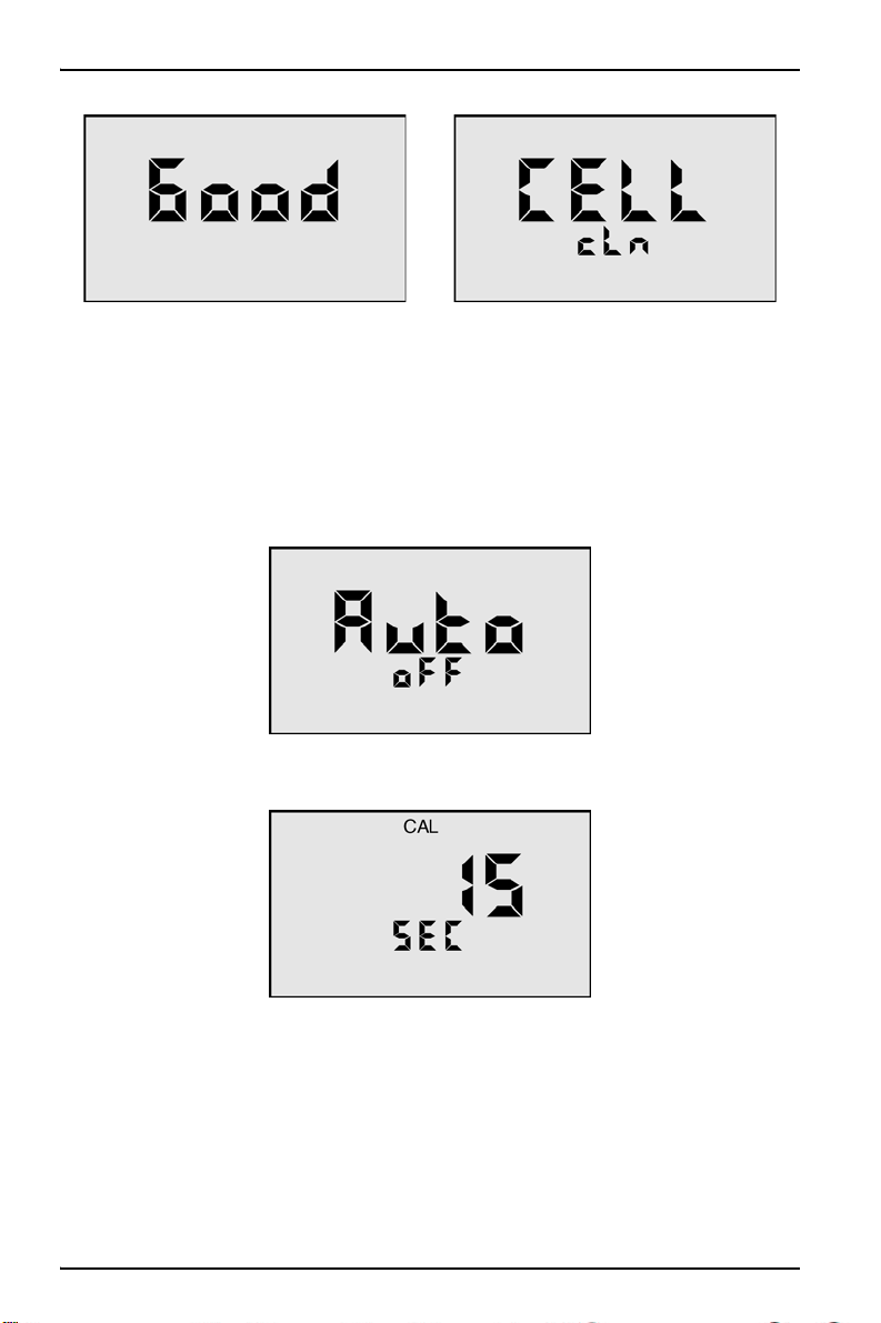
3.18 Cell check
The cell check verifies the cleanliness of the conductivity/TDS/resistivity sensor. If
the display shows .00 when the cell cup is dry, the sensor is probably clean.
In normal use, the conductivity cell may become dirty or coated and require
cleaning. To perform a cell check:
1. Push the COND key.
2. Push the MR/DOWN key repeatedly until the display shows CELL ch. To
quickly scroll through all stored memory records, hold down MR/DOWN.
3. Push the CAL/MCLR key to test. If the cell is clean, “Good” displays briefly. If
cell is dirty, “Cell cLn” displays. To clean the sensors, (see section 5.4 on
page 38).
25
Page 26
Operation
3.19 Auto off
Auto off turns the meter off when there is no activity for a period of time after a key
is pushed. The default time is 15 seconds, and 60 seconds in the CAL (calibration)
mode. This time may be adjusted up to 75 seconds.
1. Push any measurement key.
2. Push the MR/DOWN key repeatedly until the display shows Auto oFF. To
quickly scroll through all stored memory records, hold down MR/DOWN.
3. Push the CAL/MCLR key to begin. The CAL icon displays above the 15 SEC
display.
26
Page 27

Operation
4. Push UP/MS or MR/DOWN to change the time. The maximum time is 75
seconds.
5. Push the CAL/MCLR key to accept the new auto shut off time.
3.20 User mode calibration Linc
The Linc
the user does not have a user standard solution to calibrate the meter. This ensures
more accurate measurements. When the Linc function is used, the User mode is
linked to another standard solution. For example: If User and KCl are linked, a KCl
standard solution is used to calibrate the instrument.
Note: When a “Linc” is established for the User mode, the Linc applies to all measurement
modes using the User solution selection.
TM
function allows for calibration when the meter is in the User mode and
TM1
function
3.20.1 Calibrate meter for User mode
To calibrate the meter for the User mode:
1. Push the COND key, the MIN/SALT key, or the TDS key.
2. Calibrate the meter using a standard solution (see section 4.4 on page 31).
3. Select the User mode (see section 3.11 on page 19).
4. Set the calibration Linc.
3.20.2 Set User mode calibration Linc
The Linc function sets the calibration offset factor of a standard solution to the User
solution mode. The Linc stays intact in future calibrations until it is canceled (see
section 3.20.3 on page 28).
Follow the steps below to set the KCl, NaCl or 442 calibration factor to the User
solution mode.
1. Push a measurement key to Linc (i.e., COND, RES, MIN/SALT or TDS).
2. Select the User mode (see section 3.11 on page 19).
1
Trademark of Myron L Company
27
Page 28

Operation
3. Push the MR/DOWN key until Linc displays.
4. Push the CAL/MCLR key. SEL displays with the User icon.
Note: Any additional display of KCl, NaCl or 442 icons indicates a Linc between the
additional solution and the User solution. If none of the solution selection icons are
displayed, nothing is linked to the User mode.
5. Push UP/MS or MR/DOWN to select a standard solution to link to the User
mode calibration constant.
6. Push the CAL/MCLR key to accept the setting. The User mode now uses the
calibration offset constant that was created here.
Note: To exit without changing the setting, push any measurement key.
3.20.3 Cancel User mode calibration Linc
To cancel the User mode calibration Linc:
Note: The MP series meter must be in User linked mode to cancel the “Linc.”
1. Push a (linked) measurement key such as COND, RES, MIN/SALT, or TDS.
Two solutions are displayed on the left side of the display: User and another,
such as KCl.
2. Push the MR/DOWN key until Linc displays.
3. Push the CAL/MCLR key. SEL, User and the linked solution appear on the
display.
28
Page 29

Operation
4. Push the MR/DOWN key until User is the only solution icon that displays.
5. Push the CAL/MCLR key. The User mode Linc is now canceled.
3.21 Download stored data
The MP-Dock accessory package (HMPDOCK) allows the user to download stored
test data to a PC or spreadsheet. The MP-Dock receives power through the USB
port, and requires no external power source. The data is transferred through the
Infrared (IR) data port on the bottom of the MP meter (Figure 6) to the MP-Dock,
and then to the PC.
The MP Datalink software, which is included with the MP-Dock, operates on
Windows 2000 and XP, and Macintosh OS9.2 and OSX-based operating systems.
For the latest instructions on communication port selection and data download,
refer to the Hach Company MP-Dock User Manual.
1 Infrared data port
Figure 6 MP meter—bottom view
29
Page 30

Operation
30
Page 31

Section 4 Calibration
4.1 Calibration intervals
The MP Series meters are designed to not require frequent calibration. Calibration
is recommended about once per month with conductivity or TDS solutions. Check
the calibration with pH solution twice per month. Some applications may require
calibration frequencies to differ from these suggested guidelines.
4.2 Calibration limits
The MP Series meters have built in calibration limits. A nominal “FAC” value is an
ideal value stored by the factory. Attempts to calibrate too far (±10% or ±1 pH unit)
from this value causes the displayed value to be replaced with “FAC”. If the
CAL/MCLR key is pushed, the value is accepted, and the original default factory
calibration for this measurement is shown. The need to calibrate so far out that
“FAC” appears indicates a procedural problem, incorrect standard solution, a very
dirty cell cup or an aging pH/ORP sensor.
4.3 Calibration records
To minimize calibration efforts, keep records. If the calibration adjustments are
minimal, calibration can occur less often. Record the following information:
• Record changes in conductivity in percentages.
• Record changes in pH calibration in pH units.
• Conductivity cell calibration is purposely limited to
indicate damage, not drift.
• Calibration changes are limited to
end of the sensor’s lifetime and replacement is recommended.
±1 pH unit. Changes beyond that indicate the
±10%. Changes beyond that
4.4 Calibrate the meter
1. Push the measurement key for the parameter to be calibrated.
2. Push CAL/MCLR.
3. Measuring continues. The CAL icon is on. This indicates that calibration can
occur now.
4. Push UP/MS or MR/DOWN to change the reading to the known value.
5. Calibration for each of the four solution types can be performed in either
conductivity, mineral/salt or TDS mode.
Note: The number of steps to calibrate depends on what is to be calibrated.
31
Page 32

Calibration
Parameter KCl, NaCl or 442 User
COND Gain only Temperature compensation, then Gain
RES Done in conductivity Done in conductivity or TDS
TDS Gain only
MIN/SALT Gain only
pH 7, acid, and/or base
ORP Zero set with pH 7 automatically
Temperature compensation, Ratio,
then Gain
Temperature compensation, Ratio,
then Gain
6. Push the CAL/MCLR key to accept the new calibration value. The meter
accepts the value and presents the next value for adjustment. If there are no
more adjustments, the meter exits CAL mode.
Note: In the CAL mode, the CAL/MCLR key becomes an ACCEPT key. To bypass a
calibration step, push the CAL/MCLR key to accept the present value.
4.5 Exit calibration mode
When the CAL icon turns off, calibration is complete. To exit calibration mode when
the CAL icon is still on, push any measurement key. This cancels any changes not
accepted and exits the CAL mode. When CAL mode for pH is exited after the
second buffer, the meter enters the same gain for the third buffer.
4.6 Calibrate conductivity, mineral/salt or TDS
To make sure calibration is accurate, follow the items listed below.
1. Clean oily films or organic material from the conductivity cell with foaming
cleaner or mild acid.
2. Do not scrub inside the conductivity cell.
3. Rinse the conductivity cup with pure water after taking measurements.
4. Rinse the conductivity cup three times with the standard solution to be used for
calibration (KCl, NaCl, or 442).
Note: Failure to rinse can cause crystals to form in the cup and contaminate future
samples.
5. Fill the conductivity cup with same standard.
6. Push the COND key, the MIN/SALT key or the TDS key.
7. Push the CAL/MCLR key. The CAL icon appears on the display.
8. Push the UP/MS key or the MR/DOWN key to adjust to the standard value, or
hold down the key to adjust rapidly.
9. Push the CAL/MCLR key once to confirm the new value and end the
calibration sequence for this solution type.
10. To calibrate another solution type, change solution type (e.g., KCl, NaCl, or
442) and repeat this procedure.
32
Page 33

Calibration
4.7 Calibrate resistivity
Resistivity is the reciprocal of conductivity. Resistivity is automatically calibrated
based on the solution type used during a conductivity calibration.
4.8 Reset factory calibration—conductivity, mineral/salt or TDS
If calibration is suspect or known to be incorrect, and no standard solution is
available, it is possible to replace the calibrated value with the original factory value
for that solution. This ideal factory (FAC) value is the same for all MP Series
meters, and it returns to a known state without solution in the cup.
The FAC internal electronic calibration is not intended to replace calibration with
conductivity standard solutions.
1. Push the COND key, the MIN/SALT key or the TDS key.
2. Push the CAL/MCLR key twice in COND or three times in TDS.
Note: In the User mode, push the CAL/MCLR key twice in the COND mode and three
times in the TDS mode or the MIN/SALT
and ratio adjustments.)
3. Push the UP/MS key until the FAC icon appears.
4. Push the CAL/MCLR key to accept the factory calibration setting.
5. If another solution needs to be reset, select another solution type and repeat
the procedure.
mode. (This bypasses temperature correction
4.9 pH calibration
Note: Always zero-out the MP Series meter with a pH 7 buffer solution before calibrating with
acid or base buffers such as pH 4 or pH 10 solutions.
To perform a pH calibration:
1. Rinse the sensor cups three times with a pH 7 buffer solution.
2. Fill both sensor cups with pH 7 buffer solution.
3. Push the pH key to verify the pH calibration. If the display shows 7.00, skip the
pH zero calibration and proceed to section 4.10 on page 34.
33
Page 34

Calibration
4. Push the CAL/MCLR key to enter calibration mode. The CAL, BUFFER and 7
icons appear. The value displayed is for the uncalibrated sensor.
Note: If a wrong buffer is added (outside of pH 6-8), 7 and BUFFER will flash and the
meter does not adjust. The uncalibrated pH value that shows in step 4 assists in
determining the accuracy of the pH sensor. If the pH reading is below pH 6 or above pH 8
with pH 7 buffer solution, the sensor cup needs more rinses, or the pH sensor is defective
and needs to be replaced.
5. Push UP/MS or MR/DOWN until the display reads 7.00.
Note: Attempted calibration of > 1 pH point from factory calibration causes the FAC icon
to appear. This means that either sensor replacement (see Section 6 on page 41) or a
fresh buffer solution is needed. Push the CAL/MCLR key to accept the preset factory
value.
6. Push the CAL/MCLR key to accept the new value.
The pH zero calibration is now complete. It is recommended that the user performs
the multiple point pH calibration (see section 4.10). If the user does not wish to
continue, push any measurement key to exit.
4.10 Set multiple point pH calibrations
Important Note: Acid or base solution can be used for the second point calibration
and then use the other solution for the third point. To verify that a buffer is in the
sensor cup, the display shows either the Acd icon or the bAS icon.
Note: If the Acd icon or the bAS icon flash, fill the sensor cup with either an acid or base
solution to resolve the error.
1. Push the CAL/MCLR key twice while in the pH measurement mode to
complete the pH zero calibration or verify the pH 7 buffer. The CAL, BUFFER
and Acd or bAS icons are displayed.
2. Rinse the sensor cups three times with acid or base buffer solution.
3. Fill both sensor cups again with the same solution.
4. Push UP/MS or MR/DOWN until the display agrees with the buffer value.
5. Push the CAL/MCLR key to accept the second point of calibration. The display
indicates the next type of buffer to be used.
The two point calibration is complete now. The user can continue with the third
point of the calibration or exit the calibration process. Push any measurement
34
Page 35

Calibration
key to exit. If the user exits, the gain value accepted for the buffer is used for
both acid and base measurements.
6. Rinse the sensor cup three times with the third buffer solution.
7. Fill the sensor cups again with the same solution.
8. Push UP/MS or MR/DOWN until the display agrees with the buffer value.
9. Push the CAL/MCLR key to accept the third point of calibration. The calibration
procedure is now complete.
Note: Fill the pH/ORP sensor cup with pH storage solution and replace the protective sensor
cap when the meter is not in use. Do not allow the cup to dry.
4.11 ORP calibration
The ORP electrodes rarely give false readings unless there is a problem in the
reference electrode. For this reason, and because the calibration solutions for ORP
are highly reactive and potentially hazardous, the MP meter has an electronic ORP
calibration. This causes the zero point on the reference electrode to be set
whenever the pH 7 calibration is done.
4.12 Temperature calibration
Temperature calibration is not necessary in the MP series meters.
35
Page 36

Calibration
36
Page 37

Section 5 Maintenance
Practice the following care and maintenance of the MP series handheld meters:
• Rinse with clean water after each use
• Always fill the pH/ORP sensor cup with Hach pH storage solution and replace
the protective cap when not in use.
• Avoid solvents
• Avoid drops. Shock damage can damage the meter and void the warranty
5.1 Temperature extremes
Solutions in excess of 71 ºC (160 ºF) should not be placed in the sensor cups. This
activity can damage the meter. The pH sensor can fracture if the meter’s
temperature falls below 0 ºC (32 ºF). Take care not to exceed operating
temperatures.
Note: Do not leave an MP series meter in a vehicle or a storage shed on a hot day. This
activity can subject the meter to temperatures in excess of 66 ºC (150 ºF) and void the
warranty.
5.2 Battery replacement
NOTICE
If the meter is not completely dry before you open the meter, damage to the internal
electronics of the meter can occur.
Perform the following steps to replace the battery:
1. Dry the meter completely.
2. Remove the four screws from the base of the meter.
3. Open the meter carefully.
4. Take care to detach the battery from the circuit board.
5. Replace the battery with a new 9V alkaline battery.
6. Replace the bottom housing, ensuring that the sealing gasket is installed in the
groove of the top half of the case.
7. Replace the screws; tighten evenly and securely. Do not overtighten.
Note: All data stored in memory and all calibration settings are protected during power loss or
battery replacement. Loss of time and date can occur, however, if the battery is removed for
more than 3 minutes (180 seconds).
37
Page 38

Maintenance
5.2.1 Maintain the conductivity cup
Rinse the conductivity cup with clean water after taking measurements to prevent
buildup on the electrodes. Do not scrub the cup. For oily films, add a few drops of
foaming, non-abrasive cleaner or isopropyl alcohol, then rinse.
Note: When sampling low-conductivity solutions, make sure the pH/ORP sensor cap is
well-seated so that solution does not wash from the pH/ORP sensor cup into the conductivity
cup.
5.2.2 Maintain the pH/ORP sensor cup
Keep the pH/ORP sensor cup hydrated with Hach pH Storage Solution. Before
replacing the pH/ORP sensor cap, rinse and fill the sensor cup with the storage
solution. Never use distilled water to store the sensor cup.
5.3 pH/ORP sensor replacement
Complete installation instructions are included with each replacement sensor. Tools
required include a #2 Phillips screwdriver and 1/4-inch wrench.
Note: When the pH/ORP sensor is replaced, it is also a good time to replace the battery.
5.4 Clean the sensors
Perform these procedures to clean the various sensors.
5.4.1 Clean the conductivity/resistivity/TDS sensor
Keep the conductivity cell cup (Figure 7) as clean as possible.
Note: Flush with clean water after use to prevent buildup on electrodes.
When a dirty sample is left in the cup, a film forms. This film reduces accuracy.
To clean a visible film of oil, dirt or scale that is in the cell cup or on the electrode:
1. Use isopropyl alcohol or a foaming, non-abrasive household cleaner. Hach
acid electrode cleaning solution may also be used less frequently.
2. Pour any of these solutions in the cell cup and allow it to soak for no more than
five minutes.
3. Use a cotton swab to gently clean the electrodes.
4. Rinse out the cleaning solution.
38
Page 39

Maintenance
Figure 7 Model MP-6 sensor cups
1 Temperature sensor 5 pH glass electrode
2 Conductivity cell (built-in electrodes) 6 Reference junction under glass pH
bulb
3 ORP electrode 7 pH/ORP sensor protective cap
4 pH/ORP sensor (replaceable)
5.4.2 Clean the pH/ORP sensor
The pH/ORP sensor in the MP series meters is non-refillable and features a porous
liquid junction. It should not be allowed to dry out. If it does dry out, the sensor can
sometimes be restored by following the steps below.
1. Clean the sensor cup with isopropyl alcohol.
2. Rinse well. Do not scrub or wipe the pH/ORP sensor.
3. Follow the hot solution method described below:
a. Pour a hot salt solution ~60 ºC (140 ºF), such as pH storage solution in the
sensor cup.
b. Allow the liquid to cool.
c. Retest.
4. If the hot solution method does not work, follow the Deionized (DI) water
method below:
a. Pour DI water into the sensor cup.
39
Page 40

Maintenance
b. Allow to stand for no more than four hours (more standing time can deplete
the reference solution and damage the glass bulb).
c. Retest.
5. If neither of the above methods are successful, the sensor must be replaced.
5.4.2.1 Drifting test results
A film on the pH sensor bulb or the reference can cause drifting. Use isopropyl
alcohol to clean the glass bulb.
Note: The sensor bulb is very thin and delicate. Do not scrub the pH/ORP sensor.
To clean the sensor:
1. Use isopropyl alcohol or a foaming, non-abrasive household cleaner. Hach
acid electrode cleaning solution may also be used less frequently.
2. Pour any of these solutions in the cell cup and allow it to soak for no more than
five minutes.
3. Use a cotton swab to gently clean the electrodes.
4. Rinse out the cleaning solution.
5. Fill the sensor cup with Hach pH storage solution before the pH/ORP sensor
cap is replaced.
5.4.2.2 Solutions that damage the pH/ORP sensor
Samples that contain chlorine, sulfur or ammonia can damage the pH electrode.
Rinse the sensor thoroughly with clean water immediately after any measurement
of these liquids.
Samples that reduce (add an electron to) silver, such as cyanide will attack the
reference electrode.
Leaving alkaline solutions in the pH sensor cup for long periods of time can
damage the sensor.
40
Page 41

Section 6 Troubleshooting
Symptom Possible cause Action
No display even though
measurement key is
pushed
Inaccurate pH reading
No response to pH
changes (MP-6 and MP-6p
models)
Meter does not adjust
down to pH 7 (MP-6 and
MP-6p models)
pH readings drift or
respond slowly to change
or
FAC displays repeatedly
Unstable conductivity, TDS
or resistivity readings
Meter cannot calibrate
Conductivity or TDS
Resistivity reading is much
lower than expected
Battery is weak or not
connected.
pH calibration is needed
(see section 4.9 on page 33)
Cross-contamination from
residual buffers or samples
in sensor cup
Calibration with expired pH
buffers
Sensor bulb is cracked or an
electromechanical short is
caused by an internal crack.
pH sensor has lost KCl
Temporary condition due to
memory of solution in pH
sensor cup for long periods
Bulb dirty or dried out
Reference junction clogged
or coated
Dirty electrodes Clean the cell cup and the
Test samples that are
greater than 1 MΩ
Film or deposits on
electrodes
Contamination from previous
samples or from the pH
sensor cup
Carbon dioxide in the test
sample
Check the connections or
replace the battery (see
section 5.2 on page 37).
Recalibrate the meter.
Rinse the sensor cup.
Recalibrate using fresh
buffers.
Replace the pH/ORP sensor
(see section 5.3 on page 38).
Clean and restore the sensor
(see section 5.4 on page 38)
and recalibrate. If there is no
improvement, replace the
pH/ORP sensor (see
section 5.3 on page 38).
Clean and restore the sensor
(see section 5.4 on page 38)
and recalibrate. If there is no
improvement, replace the
pH/ORP sensor (refer to
section 5.3 on page 38).
electrodes (see section 5.4 on
page 38).
Minimize the test sample
exposure to air (see
section 3.6 on page 17).
Clean the cell cup and the
electrodes (see section 5.4 on
page 38
).
Rinse the sensor cup more
thoroughly before
measurement.
Make sure the pH cap is
snugly in place
(see section 5.4 on page 38).
41
Page 42

Troubleshooting
42
Page 43

Section 7 Contact Information
HACH Company World
Headquarters
P.O. Box 389
Loveland, Colorado
80539-0389 U.S.A.
Tel (800) 227-HACH
(800) 227-4224
(U.S.A. only)
Fax (970) 669-2932
orders@hach.com
www.hach.com
Repair Service in Latin
America, the Caribbean,
the Far East, Indian
Subcontinent, Africa,
Europe, or the Middle
East:
Hach Company World
Headquarters,
P.O. Box 389
Loveland, Colorado,
80539-0389 U.S.A.
Tel +001 (970) 669-3050
Fax +001 (970) 669-2932
intl@hach.com
HACH LANGE LTD
Unit 1, Chestnut Road
Western Industrial Estate
IRL-Dublin 12
Tel. +353(0)1 46 02 5 22
Fax +353(0)1 4 50 93 37
info@hach-lange.ie
www.hach-lange.ie
HACH LANGE FRANCE
S.A.S.
33, Rue du Ballon
F-93165 Noisy Le Grand
Tél. +33 (0)1 48 15 68 70
Fax +33 (0)1 48 15 80 00
info@hach-lange.fr
www.hach-lange.fr
HACH LANGE APS
Åkandevej 21
DK-2700 Brønshøj
Tel. +45 36 77 29 11
Fax +45 36 77 49 11
info@hach-lange.dk
www.hach-lange.dk
Repair Service in the
United States:
HACH Company
Ames Service
100 Dayton Avenue
Ames, Iowa 50010
Tel (800) 227-4224
(U.S.A. only)
Fax (515) 232-3835
HACH LANGE GMBH
Willstätterstraße 11
D-40549 Düsseldorf
Tel. +49 (0)2 11 52 88-320
Fax +49 (0)2 11 52 88-210
info@hach-lange.de
www.hach-lange.de
HACH LANGE GMBH
Hütteldorferstr. 299/Top 6
A-1140 Wien
Tel. +43 (0)1 9 12 16 92
Fax +43 (0)1 9 12 16 92-99
info@hach-lange.at
www.hach-lange.at
HACH LANGE SA
Motstraat 54
B-2800 Mechelen
Tél. +32 (0)15 42 35 00
Fax +32 (0)15 41 61 20
info@hach-lange.be
www.hach-lange.be
HACH LANGE AB
Vinthundsvägen 159A
SE-128 62 Sköndal
Tel. +46 (0)8 7 98 05 00
Fax +46 (0)8 7 98 05 30
info@hach-lange.se
www.hach-lange.se
Repair Service in
Canada:
Hach Sales & Service
Canada Ltd.
1313 Border Street, Unit 34
Winnipeg, Manitoba
R3H 0X4
Tel (800) 665-7635
(Canada only)
Tel (204) 632-5598
Fax (204) 694-5134
canada@hach.com
HACH LANGE LTD
Pacific Way
Salford
GB-Manchester, M50 1DL
Tel. +44 (0)161 872 14 87
Fax +44 (0)161 848 73 24
info@hach-lange.co.uk
www.hach-lange.co.uk
DR. BRUNO LANGE AG
Juchstrasse 1
CH-8604 Hegnau
Tel. +41(0)44 9 45 66 10
Fax +41(0)44 9 45 66 76
info@hach-lange.ch
www.hach-lange.ch
DR. LANGE NEDERLAND
B.V.
Laan van Westroijen 2a
NL-4003 AZ Tiel
Tel. +31(0)344 63 11 30
Fax +31(0)344 63 11 50
info@hach-lange.nl
www.hach-lange.nl
HACH LANGE S.R.L.
Via Riccione, 14
I-20156 Milano
Tel. +39 02 39 23 14-1
Fax +39 02 39 23 14-39
info@hach-lange.it
www.hach-lange.it
43
Page 44

Contact Information
HACH LANGE S.L.U.
Edif. Arteaga Centrum
C/Larrauri, 1C- 2ª Pl.
E-48160 Derio/Vizcaya
Tel. +34 94 657 33 88
Fax +34 94 657 33 97
info@hach-lange.es
www.hach-lange.es
HACH LANGE S.R.O.
Lešanská 2a/1176
CZ-141 00 Praha 4
Tel. +420 272 12 45 45
Fax +420 272 12 45 46
info@hach-lange.cz
www.hach-lange.cz
HACH LANGE
8, Kr. Sarafov str.
BG-1164 Sofia
Tel. +359 (0)2 963 44 54
Fax +359 (0)2 866 04 47
info@hach-lange.bg
www.hach-lange.bg
ÇÁCH LANGE E.Ð.Å.
БхлЯдпт 27
GR-115 27 БиЮнб
Фзл. +30 210 7777038
Fax +30 210 7777976
info@hach-lange.gr
www.hach-lange.gr
HACH LANGE LDA
Av. do Forte nº8
Fracção M
P-2790-072 Carnaxide
Tel. +351 214 253 420
Fax +351 214 253 429
info@hach-lange.pt
www.hach-lange.pt
HACH LANGE KFT.
Hegyalja út 7-13.
H-1016 Budapest
Tel. +36 (06)1 225 7783
Fax +36 (06)1 225 7784
info@hach-lange.hu
www.hach-lange.hu
HACH LANGE SU
ANALÝZ SÝSTEMLERÝ
LTD.ÞTÝ.
Hilal Mah. 75. Sokak
Arman Plaza No: 9/A
TR-06550 Çankaya/ANKARA
Tel. +90 (0)312 440 98 98
Fax +90 (0)312 442 11 01
bilgi@hach-lange.com.tr
www.hach-lange.com.tr
HACH LANGE E.P.E.
27, Avlidos str
GR-115 27 Athens
Tel. +30 210 7777038
Fax +30 210 7777976
info@hach-lange.gr
www.hach-lange.gr
HACH LANGE SP.ZO.O.
ul. Opolska 143 a
PL-52-013 Wroc³aw
Tel. +48 (0)71 342 10-83
Fax +48 (0)71 342 10-79
info@hach-lange.pl
www.hach-lange.pl
HACH LANGE S.R.L.
Str. Leonida, nr. 13
Sector 2
RO-020555 Bucuresti
Tel. +40 (0) 21 201 92 43
Fax +40 (0) 21 201 92 43
info@hach-lange.ro
www.hach-lange.ro
HACH LANGE D.O.O.
Fajfarjeva 15
SI-1230 Domžale
Tel. +386 (0)59 051 000
Fax +386 (0)59 051 010
info@hach-lange.si
www.hach-lange.si
44
Page 45

Section 8 Replacement parts and
accessories
8.1 Replacement parts
Description Item No.
pH/ORP sensor HMPSENS
9V alkaline battery 00024Q
8.2 Accessories
Description Item No.
MP-Dock (facilitates data download to PC or spreadsheet) HMPDOCK
8.3 Consumables
Description Quantity Item No.
Buffer solution, pH 4.01 50 mL 2283426
Buffer solution, pH 4.01 500 mL 2283449
Buffer solution, pH 4.01 4L 2283456
Buffer solution, pH 4.01 20 L 2283461
Buffer solution, pH 7.00 50 mL 2283526
Buffer solution, pH 7.00 500 mL 2283549
Buffer solution, pH 7.00 4 L 2283556
Buffer solution, pH 7.00 20 L 2283561
Buffer solution, pH 10.01 50 mL 2283626
Buffer solution, pH 10.01 500 mL 2283649
Buffer solution, pH 10.01 4 L 2283656
Buffer solution, pH 10.01 20 L 2283661
pH electrode storage solution, 500 mL 500 mL 2756549
pH electrode storage solution, 50 mL 50 mL 2756526
0.001M KCl Conductivity Standard Solution, 148 µS/cm 500 mL 2974249
0.001M KCl Conductivity Standard Solution, 148 µS/cm 50 mL 2974226
0.01M KCl Conductivity Standard Solution, 1413 µS/cm 500 mL 2974349
0.01M KCl Conductivity Standard Solution, 1413 µS/cm 50 mL 2974326
0.1M KCl Conductivity Standard Solution, 12.88 mS/cm 500 mL 2974449
0.1M KCl Conductivity Standard Solution, 12.88 mS/cm 50 mL 2974426
45
Page 46

Replacement parts and accessories
8.3 Consumables (continued)
Description Quantity Item No.
442-30 Natural Water™1 TDS Standard Solution, 30
ppm
442-30 Natural Water TDS Standard Solution, 30 ppm 50 mL 2974526
442-300 Natural Water TDS Standard Solution,
300 ppm
442-300 Natural Water TDS Standard Solution,
300 ppm
442-1000 Natural Water TDS Standard Solution,
1000 ppm
442-1000 Natural Water TDS Standard Solution,
1000 ppm
442-3000 Natural Water TDS Standard Solution,
3000 ppm
442-3000 Natural Water TDS Standard Solution,
3000 ppm
100 µS/cm NaCl Conductivity Standard Solution 500 mL 2971849
100 µS/cm NaCl Conductivity Standard Solution 50 mL 2971826
1000 µS/cm NaCl Conductivity Standard Solution 500 mL 1440049
1000 µS/cm NaCl Conductivity Standard Solution 50 mL 1440026
10,000 µS/cm NaCl Conductivity Standard Solution 500 mL 2972249
10,000 µS/cm NaCl Conductivity Standard Solution 50 mL 2972226
18.00 mS/cm NaCl Conductivity Standard Solution 500 mL 2307449
18.00 mS/cm NaCl Conductivity Standard Solution 50 mL 2307426
1
Trademark of Myron L Company
500 mL 2974549
500 mL 2974649
50 mL 2974626
500 mL 2974749
50 mL 2974726
500 mL 2974849
50 mL 2974826
8.4 Recommended cleaning consumables
Description Quantity Item No.
Isopropyl alcohol 100 mL 1227642
Isopropyl alcohol prep pads 200/pk 2938200
Cotton swabs 100/pkg 2554300
Acid electrode cleaning solution 50 mL 2975126
Acid electrode cleaning solution 500 mL 2975149
46
Page 47

Section 9 Limited Warranty
Hach Company warrants to the original purchaser against any defects that are due
to faulty material or workmanship for a period of two years from date of shipment
unless otherwise noted in the product manual.
In the event that a defect is discovered during the warranty period, Hach Company
agrees that, at its option, it will repair or replace the defective product or refund the
purchase price excluding original shipping and handling charges. Any product
repaired or replaced under this warranty will be warranted only for the remainder of
the original product warranty period.
This warranty does not apply to consumable products such as chemical reagents;
or consumable components of a product, such as, but not limited to, lamps and
tubing.
Contact Hach Company or your distributor to initiate warranty support. Products
may not be returned without authorization from Hach Company.
Warranty Limitations
This warranty does not cover:
• Damage caused by acts of God, natural disaster, labor unrest, acts of war
(declared or undeclared), terrorism, civil strife or acts of any governmental
jurisdiction
• Damage caused by misuse, neglect, accident or improper application or
installation
• Damage caused by any repair or attempted repair not authorized by Hach
Company
• Any product not used in accordance with the instructions furnished by Hach
Company
• Freight charges to return merchandise to Hach Company
• Freight charges on expedited or express shipment of warranted parts or product
• Travel fees associated with on-site warranty repair
This warranty contains the sole express warranty made by Hach Company in
connection with its products. All implied warranties, including without limitation, the
warranties of merchantability and fitness for a particular purpose, are expressly
disclaimed.
Some states within the United States do not allow the disclaimer of implied
warranties and if this is true in your state the above limitation may not apply to you.
This warranty gives you specific rights, and you may also have other rights that vary
from state to state.
This warranty constitutes the final, complete, and exclusive statement of warranty
terms and no person is authorized to make any other warranties or representations
on behalf of Hach Company.
Limitation of Remedies
The remedies of repair, replacement or refund of purchase price as stated above
are the exclusive remedies for the breach of this warranty. On the basis of strict
liability or under any other legal theory, in no event shall Hach Company be liable
for any incidental or consequential damages of any kind for breach of warranty or
negligence.
47
Page 48

Limited Warranty
48
Page 49

Appendix A Temperature compensation
Electrical conductivity indicates solution concentration and ionization of the
dissolved material. Because temperature greatly affects ionization, conductivity
measurements are temperature dependent, and are normally corrected to read
what they would be at 25 ºC.
A.1 Compensation to 25 ºC
The MP series handheld meters includes temperature compensation to 25 ºC.
Temperature compensation can be set to KCl, NaCl or 442 solutions or tailored for
special measurements or applications.
A.2 Changes in temperature compensation
Most conductivity meters approximate the temperature characteristics of solutions,
and assume a constant value, such as, 2%/ºC. In fact, KCl temperature
compensation changes with concentration and temperature in a non-linear fashion.
Other solutions change even more. The MP series handheld meters use
compensations that change with concentration and temperature instead of single
average values (Figure 8).
Figure 8
49
Page 50

Temperature compensation
A.3 Graph of comparative error
In the range of 1000 µS, the error of using a KCl temperature compensation on a
solution that should be calculated as NaCl or 442 is shown in the chart below
(Figure 9).
Figure 9
To measure natural water-based solutions to 1%, users must alter the internal
temperature compensation to the more suitable, pre-loaded 442 values or stay
close to 25 ºC.
A.4 Other solutions
A salt solution like sea water or liquid fertilizer acts like NaCl. The NaCl solution
compensation provides the greatest accuracy for these solutions.
Many solutions differ greatly from KCl, NaCl or 442. A sugar solution, a silicate, or a
calcium salt at a high or low temperature may require a User value to provide
readings close to the true compensated conductivity. This is determined
experimentally.
The chosen solution characteristic should closely match the sample being tested to
achieve accuracy of ±1%.
50
Page 51

Appendix B Conductivity conversion
B.1 How conductivity conversion works
When the effect of temperature is removed, the corrected conductivity depends on
the concentration (TDS). Temperature compensation of the conductivity of a
solution is performed automatically by the meter’s internal processor with data
derived from chemical tables. Any dissolved salt at a known temperature has a
known ratio of conductivity to concentration. Tables of conversion ratios referenced
to 25 ºC have been published by chemists for decades.
B.2 Solution characteristics
Real-world applications have to measure a wide range of materials and mixtures of
electrolyte solutions. To address this problem, industry applications tend to use the
characteristics of a standard material as a model for their solution, such as KCl,
which is favored by chemists for its stability.
Users who deal with sea water, etc., use NaCl as the model for their concentration
calculations. Users who deal with freshwater work with mixtures including sulfates,
carbonates and chlorides. These are modeled in the 442 standard solutions.
The meter contains algorithms for these three most commonly referenced
compounds. The solution type in use is shown on the left side of the display. In
addition to KCl, NaCl, and 442, a User choice is available. The User mode allows
the user to enter the temperature compensation and TDS ratio by hand. This
increases the accuracy of readings for a specific solution. That value remains a
constant for all measurements, and should be reset for different dilutions or
temperatures.
51
Page 52

Conductivity conversion
52
Page 53

Appendix C Temperature compensation and TDS derivation
The MP series handheld meters contain internal algorithms for characteristics of the
three most commonly referenced compounds. The selected solution type is shown
on the left of the display. In addition to KCl, NaCl and 442, a User choice is
available. The User mode allows the user to enter the temperature compensation
and the TDS conversion ratio of a unique solution.
C.1 Conductivity characteristics
When taking conductivity measurements, the Solution Selection determines the
characteristic assumed as the instrument reports what a measured conductivity
would be if it were at 25 °C. The characteristic is represented by the temperature
compensation, expressed in %/°C.
If a solution of 100 µS at 25 °C increases to 122 µS at 35 °C, then a 22% increase
has occurred over this change of 10 °C. The solution is then said to have a
temperature compensation of 2.2%/°C.
Temperature compensation always varies among solutions because it is dependent
on their individual ionization activity, temperature and concentration. This is why the
MP meters feature mathematically generated models for known salt characteristics
that also vary with concentration and temperature.
C.2 Temperature compensation of unknown solutions
The user may need to find the corrected conductivity of a solution that differs from
the three standard salts. In order to enter a custom fixed temperature compensation
for a limited measurement range, enter a specific value through the User function.
The temperature compensation can be determined by two different methods.
C.2.1 Find temperature compensation by calculation
1. Heat or cool a sample of the solution to 25 ºC, and measure its conductivity.
2. Heat or cool the solution to a typical temperature where it is normally
measured.
3. Select the User function.
4. Set the temperature compensation to 0%/ºC (see section 3.12.1 on page 20).
5. Measure the new conductivity and the new temperature.
6. Divide the percentage decrease or percentage increase by the 25 ºC value.
7. Divide that result by the temperature difference.
C.2.2 Find temperature compensation by adjustment
1. Heat or cool a sample of the solution to 25 ºC, and measure its conductivity.
2. Heat or cool the solution to a typical temperature where it is normally
measured.
53
Page 54

Temperature compensation and TDS derivation
3. Set the temperature compensation to an expected value (see section 3.12 on
page 20).
4. See if the compensated value is the same as the 25 ºC value.
5. If the value is not the same, raise or lower the temperature compensation and
measure again until the 25 ºC value is read.
C.3 TDS ratio of unknown solutions
When the effect of temperature is removed, the compensated conductivity varies
with the concentration (TDS). The ratio of TDS to compensated conductivity for any
solution also varies with concentration. The ratio is set during calibration in the User
mode (see section 3.13 on page 20). Measure the TDS of an unknown solution by
evaporation and weighing. Then measure the conductivity of the solution, with the
now-known TDS, and calculate the ratio. The next time this solution is measured,
the ratio is known.
54
Page 55

Appendix D Additional information on pH and ORP (MP-6 and MP-6p models)
D.1 pH
D.1.1 pH as an indicator
pH measures the acidity or alkalinity of an aqueous solution. Another way to
describe pH is as the hydrogen ion activity of a solution.
pH measures the effective, not the total acidity of a solution. A 4% solution of acetic
acid (pH 4, vinegar) can be quite palatable, but a 4% solution of sulfuric acid (pH 0)
is a violent poison. pH provides the needed quantitative information by expressing
the degree of activity of an acid or base.
In a solution of one known component, pH indicates concentration directly. Very
dilute solutions may be very slow reading because very few ions take time to
accumulate.
D.1.2 pH units
The acidity or alkalinity of a solution measures the relative availability of hydrogen
+
) and hydroxide (OH-) ions. An increase in H+ ions increases acidity, while an
(H
increase in OH
pH is defined as the negative logarithm of hydrogen ion concentration. Where
+
concentration falls below 10-7 mol/liter, solutions are less acidic than neutral, and
H
therefore are alkaline. A concentration of 10
ions than OH
-
ions increases alkalinity.
-9
-
ions and is an alkaline solution of pH 9.
mol/liter of H+ has 100 times less H+
D.1.3 pH sensor
The active part of a pH sensor is a thin glass surface that is selectively receptive to
hydrogen ions. Available hydrogen ions in a solution accumulate on this surface
and a charge builds up across the glass interface. The voltage can be measured
with a high impedance voltmeter circuit.
The glass surface encloses a captured solution of potassium chloride that holds an
electrode of silver wire coated with silver chloride. This is the most inert connection
possible from a metal to an electrolyte. It can still produce an offset voltage, but
using the same materials to connect to the solution on the other side of the
membrane cancels the two equal offsets.
The other electrode, also called the reference junction, allows the junction fluid to
contact the test solution, without significant migration of liquids, through the plug
material.
The pH/ORP sensor in the MP series meters (MP-6 and MP-6p) (Figure 10) is a
single construction in an easy-to-replace package. The sensor body holds an
oversize solution supply for long life. The reference junction is a wick that is porous
so that it can provide a stable, low, permeable interface. It is located under the
glass pH sensing electrode.
55
Page 56

Additional information on pH and ORP (MP-6 and MP-6p models)
.
Figure 10 pH/ORP sensor construction
1 Glass surface 5 KCl solution
+
ions 6 Glass
2 H
3 Junction plug 7 Electrode wires
4 Platinum button
D.1.4 Sources of error
D.1.4.1 Reference junction
The most common sensor problem is a clogged junction because a sensor is
allowed to dry out. The symptom is a drift in the zero setting at pH 7. This explains
why MP series meter does not allow more than one pH unit of offset during
calibration.
D.1.4.2 Sensitivity errors
Sensitivity is the receptiveness of the glass surface. A film on the surface can
diminish the sensitivity and cause a long response time.
56
Page 57

Additional information on pH and ORP (MP-6 and MP-6p models)
D.1.5 Temperature compensation
pH sensor glass changes sensitivity slightly with temperature. When the solution is
further from pH 7, this effect increases. For example, a pH of 11 at 40 ºC is off by
0.2 units. The MP series meter senses the sensor cup temperature and
compensates the reading.
D.2 Oxidation Reduction Potential/Redox (ORP)
D.2.1 ORP as an indicator
ORP measures the ratio of oxidizing activity to reducing activity in a solution. It is
the potential of a solution to give up electrons (to oxidize other things) or gain
electrons (reduce).
Similar to acidity and alkalinity, one aspect increases at the expense of the other.
Therefore, a single voltage is called the Oxidation-Reduction Potential, and a
positive voltage shows a solution that wants to steal electrons (an oxidizing agent).
For example, chlorinated water shows a positive ORP value.
D.2.2 ORP units
ORP is measured in millivolts, with no correction for solution temperature. Like pH,
it is not a measurement of concentration directly, but of activity level. In a solution of
only one active component, ORP indicates concentration. Also, similar to pH, a very
dilute solution takes time to accumulate a readable charge.
D.2.3 ORP sensor
An ORP sensor uses a small platinum surface to accumulate charge without
reacting chemically. That charge is measured relative to the solution, so the
solution “ground” voltage comes from a reference junction. Figure 10 shows the
platinum button in a glass sleeve. The same reference is used for both the pH and
the ORP sensors. Both pH and ORP indicates 0 for a neutral solution. Calibration at
zero corrects the error in the reference junction.
A zero calibration solution for ORP is not practical, so the MP series meters use the
offset value determined during calibration to 7 in pH calibration (pH 7 = 0 mV).
Sensitivity of the ORP surface is fixed so there is no gain adjustment.
D.2.4 Sources of error
Sources of error are similar to pH. Even though the platinum surface does not
break like the glass pH surface, its protective glass sleeve can be broken. A surface
film will slow the response time and diminish sensitivity.
57
Page 58

Additional information on pH and ORP (MP-6 and MP-6p models)
58
Page 59

Index
B
battery replacement ......................37
C
calibrate
conductivity, mineral/salt or TDS
................................ 32
ORP ..................................... 35
pH ........................................ 33
pH in multiple points ............... 34
resistivity ............................... 33
temperature ........................... 35
calibrate meter for user mode ........27
calibrate the meter ........................31
calibration
intervals
limits ..................................... 31
records ................................. 31
cancel User mode calibration Linc ..28
cell check ....................................25
change the temperature compensation
factor ..........................................20
Change the user-selected
conductivity/TDS ratio
check the cell ...............................25
clean the conductivity/resistivity/TDS
sensor .........................................38
clean the pH/ORP sensor ..............39
cleaning consumables ..................45
clear a single record .....................22
clear all records ............................22
company contact information .........43
conductivity and pH/ORP sensor cups
................................ 31
...................20
....................................................13
conductivity characteristics ............53
conductivity conversion .................51
conductivity cup
clean the cup
consumables ...............................45
......................... 38
D
data port ......................................29
default settings .............................25
description of the display ...............15
disable temperature compensation .20
download data .............................29
drifting test results ........................40
E
exit calibration mode .....................32
extreme temperatures ...................37
F
features common to all models ......12
find temperature compensation
by adjustment
by calculation ........................ 53
........................ 53
G
general product information ...........12
I
items on the display ......................15
K
keypad descriptions ......................16
keypads ......................................16
L
Linc function ................................27
M
maintain the conductivity cup .........38
maintain the pH/ORP sensor cup ...38
measure
conductivity
mineral/salt ........................... 18
ORP/Redox ........................... 18
pH ........................................ 18
resistivity ............................... 17
TDS ..................................... 18
measure resistivity ........................17
memory settings ...........................21
MP-Dock .....................................29
........................... 17
O
ORP
as an indicator
Hach ORP sensor .................. 57
sources of error ..................... 57
....................... 57
59
Page 60

Index
units .....................................57
other solutions ............................. 50
overview of the meters ................. 12
P
pH
as an indicator
sensor .................................. 55
sources of error ...................... 56
units .....................................55
pH/ORP sensor replacement ........ 38
power on/off the meter ................. 15
.......................55
R
replacement parts and accessories 45
reset factory calibration ................ 33
return to factory settings ............... 25
S
safety information ........................ 11
select a solution .......................... 19
select the user mode .................... 19
sensor
clean
.................................... 38
sensor cup
hydrate
.................................38
sensor replacement ..................... 38
set the date ................................. 23
set the time ................................. 22
set user mode calibration Linc ....... 27
solution characteristics ................. 51
solution types .............................. 19
solutions that damage the pH/ORP
sensor .........................................40
specifications .................................7
store a value in the memory ...........21
T
take a measurement .....................17
TDS ratio of unknown solutions ......54
temperature compensation
compensation to 25ºC
temperature compensation and TDS
derivation ....................................53
temperature compensation of unknown
solutions ......................................53
temperature extremes ...................37
temperature format .......................24
time and date ...............................22
troubleshooting ............................41
turn on/off the meter .....................15
............ 49
U
use of hazard information ..............11
user mode ...................................19
user mode calibration Linc function .27
user mode features .......................12
user solution ................................19
V
view the memory recall .................22
view the records ...........................22
W
warranty ......................................47
60
 Loading...