

Page 1

DOC026.97.80340
MET ONE 6000: 6003, 6005,
6013, 6015
05/2013, Edition 2
Basic User Manual
Manuel d'utilisation de base
Manual básico del usuario
基本用户手册
基本取扱説明書
기본 사용 설명서
Page 2

English...................................................................................................................................................................................................
Français..............................................................................................................................................................................................24
Español...............................................................................................................................................................................................48
中文.......................................................................................................................................................................................................72
日本語..................................................................................................................................................................................................91
한글.....................................................................................................................................................................................................113
3
2
Page 3

Table of contents
Specifications on page 3 Startup on page 15
General information on page 4 Operation on page 16
Installation on page 8 Maintenance on page 23
Specifications
Specifications are subject to change without notice.
Specification Details
Dimensions (W x D xH)13.56 x 8.93 x 12.06 cm (5.34 x 3.52 x 4.75 in.)
Enclosure 304 stainless steel
Light source Long Life Laser™ diode , Class 3B laser
Weight 0.82 kg (1.8 lb)
Pollution degree 2
Installation category I
Protection class III
Power requirements 9–28 VDC (source: Class 2 limited energy, < 150 VA)
Power consumption
(maximum)
Operating
temperature
Storage temperature –40 to 70 °C (–40 to 158 °F)
Humidity Operating and storage: 5 to 95% relative humidity, non-
Altitude 2000 m (6562 ft) maximum
Serial and pulse units: 3.3 W; Ethernet unit: 4.3 W;
Analog: 3.5 W; 1 A maximum
5 to 40 °C (40 to 104 °F); best performance: 10 to 32 °C
(50 to 90 °F)
condensing
Specification Details
Port sizes Model 6003, 6005: barb fitting for 0.32 cm (1/8-in.) ID
Output signal options Pulse, analog 4–20 mA, serial RS232 with Modbus RTU
Data storage 1000 samples/records (oldest records are written over
Sample flow rate Model 6003, 6005: 0.1 cfm (2.83 Lpm) ± 5%
Inlet pressure Ambient to 2.5 mm (0.1 in) Hg vacuum
Vacuum requirement ≥ 406 mm (16 in.) Hg (542 mbar) minimum vacuum
Range Model 6003: 0.3 μm to 10.0 μm at 0.1 cfm (2.83 L/min)
Sensitivity Model 6003: 0.3 μm at 0.1 cfm (2.83 L/min)
Counting efficiency Model 6003: 50% (± 20%) for 0.3 μm, (100% ± 10% at
Coincidence loss Model 6003, 6005 (all output options): 10% at
inlet tubing, 0.64 cm (¼-in.) ID outlet tubing
Model 6013, 6015: barb fitting for 0.64 cm (¼-in.) ID inlet
tubing, 0.64 cm (¼-in.) ID outlet tubing
or FXB communication protocol (no networking), serial
RS485 with Modbus RTU or FXB communication
protocol, Ethernet with ModbusTCP protocol
when the buffer is full)
Model 6013, 6015: 1.0 cfm (28.3 Lpm) ± 5%
measured at each instrument with flow through all
instruments.
Model 6005: 0.5 μm to 10.0 μm at 0.1 cfm (2.83 L/min)
Model 6013, 6015: 0.5 μm to 10.0 μm at 1.0 cfm
(28.3 L/min)
Model 6005: 0.5 μm at 0.1 cfm (2.83 L/min)
Model 6013: 0.3 μm at 1.0 cfm (28.3 L/min)
Model 6015: 0.5 μm at 1.0 cfm (28.3 L/min)
1.5 times the minimum sensitivity)1.
Model 6005, 6013, 6015: 50% (± 20%) for 0.5 μm, (100%
± 10% at 1.5 times the minimum sensitivity)1.
140,000,000 particles /m3 (4,000,000 particles /ft3)
Model 6013, 6015 (all output options except for pulse):
10% at 20,000,000 particles/m3 (566,000/ft3)
English 3
Page 4

Specification Details
False count rate One or less in 5 minutes
Certifications CE
1
Fully complies with ISO21501-4.
General information
In no event will the manufacturer be liable for direct, indirect, special,
incidental or consequential damages resulting from any defect or
omission in this manual. The manufacturer reserves the right to make
changes in this manual and the products it describes at any time, without
notice or obligation. Revised editions are found on the manufacturer’s
website.
Expanded manual version
For additional information, refer to the CD for an expanded version of
this manual.
Safety information
N O T I C E
The manufacturer is not responsible for any damages due to misapplication or
misuse of this product including, without limitation, direct, incidental and
consequential damages, and disclaims such damages to the full extent permitted
under applicable law. The user is solely responsible to identify critical application
risks and install appropriate mechanisms to protect processes during a possible
equipment malfunction.
Please read this entire manual before unpacking, setting up or operating
this equipment. Pay attention to all danger and caution statements.
Failure to do so could result in serious injury to the operator or damage
to the equipment.
Make sure that the protection provided by this equipment is not impaired.
Do not use or install this equipment in any manner other than that
specified in this manual.
Use of hazard information
D A N G E R
Indicates a potentially or imminently hazardous situation which, if not avoided, will
result in death or serious injury.
Indicates a potentially or imminently hazardous situation which, if not avoided,
could result in death or serious injury.
Indicates a potentially hazardous situation that may result in minor or moderate
injury.
Indicates a situation which, if not avoided, may cause damage to the instrument.
Information that requires special emphasis.
W A R N I N G
C A U T I O N
N O T I C E
Precautionary labels
Read all labels and tags attached to the instrument. Personal injury or
damage to the instrument could occur if not observed. A symbol on the
instrument is referenced in the manual with a precautionary statement.
This symbol, if noted on the instrument, references the instruction
manual for operation and/or safety information.
This symbol, when noted on a product enclosure or barrier, indicates
that a risk of electrical shock and/or electrocution exists.
4 English
Page 5

This symbol indicates a laser device is used in the equipment.
Electrical equipment marked with this symbol may not be disposed of
in European public disposal systems after 12 August of 2005. In
conformity with European local and national regulations (EU Directive
2002/96/EC), European electrical equipment users must now return
old or end-of-life equipment to the Producer for disposal at no charge
to the user.
Note: For return for recycling, please contact the equipment producer or supplier
for instructions on how to return end-of-life equipment, producer-supplied
electrical accessories, and all auxillary items for proper disposal.
Laser safety information
This instrument is a CLASS 1 LASER PRODUCT, CDRH Accession No.
9022243-029. Invisible laser radiation is present when opened. Avoid
direct exposure to the beam. Service of the internal components must be
done by factory-authorized personnel only.
The instrument complies with IEC/EN 60825-1 and 21 CFR
1040.10 except for deviations pursuant to Laser Notice No. 50, dated
June 24, 2007.
Certification
Canadian Radio Interference-Causing Equipment Regulation,
IECS-003, Class A:
Supporting test records reside with the manufacturer.
This Class A digital apparatus meets all requirements of the Canadian
Interference-Causing Equipment Regulations.
Cet appareil numèrique de classe A répond à toutes les exigences de la
réglementation canadienne sur les équipements provoquant des
interférences.
FCC Part 15, Class "A" Limits
Supporting test records reside with the manufacturer. The device
complies with Part 15 of the FCC Rules. Operation is subject to the
following conditions:
1. The equipment may not cause harmful interference.
2. The equipment must accept any interference received, including
interference that may cause undesired operation.
Changes or modifications to this equipment not expressly approved by
the party responsible for compliance could void the user's authority to
operate the equipment. This equipment has been tested and found to
comply with the limits for a Class A digital device, pursuant to Part 15 of
the FCC rules. These limits are designed to provide reasonable
protection against harmful interference when the equipment is operated
in a commercial environment. This equipment generates, uses and can
radiate radio frequency energy and, if not installed and used in
accordance with the instruction manual, may cause harmful interference
to radio communications. Operation of this equipment in a residential
area is likely to cause harmful interference, in which case the user will be
required to correct the interference at their expense. The following
techniques can be used to reduce interference problems:
1. Disconnect the equipment from its power source to verify that it is or
is not the source of the interference.
2. If the equipment is connected to the same outlet as the device
experiencing interference, connect the equipment to a different
outlet.
3. Move the equipment away from the device receiving the interference.
4. Reposition the receiving antenna for the device receiving the
interference.
5. Try combinations of the above.
Product overview
This instrument
and collection optics. Refer to Figure 1. Room air is pulled through the
particle counter by an attached, external vacuum system.
Multiple instruments can be installed at different locations in a clean
room to monitor the air quality. Count data is sent to the user-supplied
central monitoring software through the applicable communication
protocols. The central monitoring software is used to remotely operate
the instrument.
The sensor flow path is resistant to vaporous hydrogen peroxide (VHP)
for VHP-based standard clean room disinfection and cleaning cycles.
counts airborne particles with a laser diode light source
English 5
Page 6

Figure 1 Product overview
Table 1 Status indicator light (continued)
Color Indication System status
Blue On Sensor failure
One short flash, one long flash Air flow failure
Flashing Communication failure
Red On or flashing Count alarm
Yellow On Initialization
Flashing Count alert
Purple Flashing Setup utility is being used
1
The user-supplied central monitoring software can be used to make the yellow
light flash when a count alert occurs with ModBus protocol, not FX protocol.
The count alert settings are selected with the central monitoring software.
1
1 Power input and communication
connector, 10-pin
2 Vacuum source fitting (or quick-
connect fitting)
3 Sample air inlet fitting 9 Connection indicator lights
4 Status indicator light (Table 1) 10 Ethernet RJ45 connector
5 Service port and optional light stack
port
6 DIP switch, network address
1
All units except Ethernet
2
Ethernet units only
1
1
7 Relative humidity (RH) and
temperature sensor port
8 Vacuum source fitting (alternate
location)
(Table 2)
11 Power input connector, 5-pin
Table 1 Status indicator light
Color Indication System status
Green Flashing (3 seconds) Normal, sampling
On Normal, not sampling
6 English
Table 2 Ethernet indicator lights
Color Indication Status
Yellow On Connected
2
2
2
Green Off 10Base-T
On 100Base-T
Isokinetic probe
For the best accuracy in laminar flow environments, always use the
supplied isokinetic probe with this
instrument. The velocity of air in the
probe is similar to that of a typical vertical or horizontal laminar flow
environment such as a clean room or clean hood. The supplied
isokinetic probe supplies the same vertical (or horizontal) flow speed of
the air in order to collect representative samples of the clean room
laminar flow for the instrument. Refer to Figure 2 for a comparison of
sampling with and without the isokinetic probe.
Page 7

Figure 2 Isokinetic probe function
1 No probe in non-laminar air flow 3 No probe in laminar air flow—
particles are missed
2 To particle counter 4 Isokinetic probe in laminar air flow
—most accurate
Instrument configurations
This instrument is available in many configurations. Each configuration
has a different part number. Figure 3 shows the part number structure.
Table 3 gives descriptions of the part number codes.
Figure 3 Part number structure
1 Flow rate 3 Exhaust location 5 Communication
2 Sensitivity (minimum) 4 Flow measurement
Table 3 Parameter codes
Parameter Code Description Parameter Code Description
Flow rate 0 0.1 cfm
(for 0.3 µm
and 0.5 µm
sensitivity)
1 1.0 cfm
(for 0.5 µm
sensitivity
only)
Sensitivity
(minimum)
Exhaust
location
Example: An instrument with a 0.1 cfm flow rate, 0.5 μm sensitivity, bottom
exhaust port, flow measurement and RS485 communication will have the part
numbers 2088605-DF-S and 20888600-485. The second part number is
necessary to identify the type of serial communication (RS232 = 20888600-232,
RS485 = 20888600-485 or Pulse = 20888600-PLS). The second part number is
not necessary for any other communication type.
3 0.3 µm Communication E Ethernet
5 0.5 µm S Serial I/O
D Down
(bottom)
S Side
Flow
measurement
F With flow
measurement
N Without flow
measurement
options
A Analog
English 7
Page 8

Product components
Make sure that all components have been received. Refer to Figure 4. If
any items are missing or damaged, contact the manufacturer or a sales
representative immediately.
Figure 4 Instrument components
1 MET ONE 6000 series particle
counter
2 Sample (isokinetic) probe with
1
tube
3 Sample (isokinetic) probe with
2
tube
4 DIN rail mounting kit 8 Service port cable (8-pin DIN to 9-
1
1.0 cfm units only
2
0.1 cfm units only
3
All units except Ethernet
4
Ethernet only
5
Only one service port cable is supplied per order.
5 10-pin connector with clam shell
6 5-pin connector with clam shell
7 Setup utility CD
pin serial connector)
5
3
4
Installation
Installation guidelines
N O T I C E
Before a cleaning or disinfecting cycle is started, stop the vacuum pump and put
a cover on the air inlet fitting.
High internal temperatures cause damage to the instrument components.
• Install the instrument indoors in a clean, dry, well ventilated,
temperature controlled location with minimum vibration.
•
If the room is washed down at regular intervals, install the instrument
outside of the room. Only the air inlet and vacuum tubes will go into
the clean room. As an alternative, put the instrument in the clean room
in a sealed box. Connect all tubes and cables to the instrument
through the box. Operation of the instrument in an enclosed box may
increase the temperature around the instrument and decrease the
performance and life of the instrument.
• Do not operate the instrument in direct sunlight or next to a heat
source.
• Install the instrument as close to the sample source as possible. Make
sure that the distance is not more than 3 m (10 ft). An inlet tube length
longer than 3 m (10 ft) can cause a loss of particles larger than 1 μm.
If an inlet tube length longer than 3 m (10 ft) is necessary, compare
the results between a portable particle counter and this instrument.
• Keep the air flow in a constant downward direction. When possible,
mount the instrument directly below the sample point.
Vacuum system guidelines
• Put the vacuum pump in a central location. There must be sufficient
vacuum for all instruments in the network.
• Use a distribution manifold that keeps vacuum loss to a minimum.
Typical materials used for vacuum distribution include brazed copper
pipe, schedule 80 PVC pipe or tubing such as Cobolite®.
N O T I C E
8 English
Page 9

• Use short tubing lengths to supply the vacuum from the distribution
manifold to the individual
barb fitting of the correct dimension at each instrument location.
• Keep the number of junctions, elbows and the tubing length from the
vacuum source to the instruments to a minimum to keep the vacuum
loss in a system to a minimum.
instrument. Use a distribution valve and a
Mechanical installation
Instrument mounting
Install the instrument on a level surface or on a wall with one of these
mounting kits:
• DIN rail kit (supplied with the instrument)—use to quickly remove the
instrument from the wall.
• Wall mounting bracket (optional)—use for permanent installation.
Refer to the instructions supplied with the kit.
Refer to the illustrated steps in Figure 5 for DIN rail installation. To
remove the instrument from the rail, lift the bottom of the instrument.
Figure 5 DIN rail installation
English 9
Page 10

Install the sample probe
Refer to Sample probe guidelines on page 10
prevent contamination of the instrument and to get a representative
sample of the area. The position of the sample (isokinetic) probe is
important for count accuracy.
Sample probe options
Optional kits are available for sample probe installation. Refer to
Figure 6.
• Direct mount—No kit is necessary. The sample probe is installed on
a short piece of tubing directly on top of the sample air inlet fitting on
the instrument. Use direct mount installation when the instrument can
be put in the location where the sample is collected. Use the direct
mount installation to keep particle loss to a minimum.
• Wall mount, 90 degree—The probe is connected to a stainless steel
tube (90 degree) and a wall bracket.
• T-type wall bracket—The sample probe is installed in a wall bracket.
The tubing is cut to connect the probe to the counter.
• Vertical wall mount—The sample probe is connected to a stainless
steel tube and bracket. Use vertical wall mount installation on
equipment with stainless steel tubing.
before the installation to
Figure 6 Sample probe installation options
1 Direct mount 3 Vertical wall mount
2 Wall mount, 90 degree 4 T-type wall bracket
Sample probe guidelines
N O T I C E
Do not use this instrument to monitor air that contains vapors from drying
adhesives or other chemicals. These vapors can permanently coat the sensor
optics or other internal parts.
Do not use this instrument to monitor air that contains vapors with corrosives.
These vapor will quickly cause permanent damage to the optics or electronics of
the counter.
• Laminar flow—Install at least one sample probe for every 2.3 m
N O T I C E
2
(25 ft2) of surface area.
10 English
Page 11

• Turbulent flow—Install at least two sample probes in each clean room.
•
Make sure that the sample (isokinetic) probe points to the direction of
flow. Refer to Figure 2 on page 7.
• Keep the sample probe a minimum of 30 cm (12 in.) from loose
materials, dust, liquids and sprays.
• Keep the sample probe a minimum of 30 cm (12 in.) from potential
contamination sources such as an instrument exhaust fan.
• Do not use this instrument to monitor air that contains the substances
shown in Table 4.
Table 4 Contaminants
Substance Damage
Powders Contaminates the sensor and causes incorrect results or
Liquids Contaminates the internal optics of the sensor and changes the
Smoke Contaminates the sensor
instrument failure
calibration of the instrument
Note: Liquids can be in the air in the form of oil droplets.
Install the tubing
Use tubing hooks or cable ties to hold the tubing and prevent a bend in
the tubing. A bend in the tubing will decrease the air flow and cause the
problem that follow
• A decrease in air inlet flow can cause particles to collect on the interior
walls of the tubing. The particles will not be counted. The collected
particles can release at random, which will cause spikes in the count
level.
Items to collect:
• Air inlet tubing—Hytrel® Bevaline, Tygon® or equivalent
• Vacuum tubing—Hytrel Bevaline, Tygon or equivalent
• Tubing hooks or cable ties
1. Cut the air inlet tubing to a length sufficient to connect the instrument
to the sample probe. Keep the tube length to a minimum. Make sure
that the length is not more than 3 m (10 ft).
s:
2. Cut the vacuum tubing to connect the counter to the vacuum source.
Keep the tube length to a minimum.
3. Put a cover on the tube ends to make sure that unwanted material
does not go in the tubes during installation.
4. Attach the tubing with hooks or cable ties at intervals that are not
more than 1.2 m (4 ft) apart. Make sure that the tubing has a
minimum bend radius of 10 cm (4 in.) so air flow is not decreased.
5. Connect the air inlet tubing to the air inlet fitting on the
instrument.
Connect the other end of the tubing to the supplied sample probe.
6. Connect the vacuum tubing to the fitting on the bottom (or side) of
the counter. Do not connect the other end to the vacuum until the
room is ready for sampling.
Electrical installation
Wiring safety information
W A R N I N G
Electrocution hazard. Make sure that there is easy access to the local
power disconnect.
N O T I C E
Always disconnect power to the instrument before electrical connections are
made.
Obey all safety statements while connections are made to the
instrument.
Connect to power
Connect an external power source (24 VDC) to the 5-pin or 10-pin
connector. Refer to Figure 7 and Table 5 or Figure 8 and Table 6 for
wiring information. Make sure that the output voltage of the external
power source does not exceed 28 VDC.
The maximum number of
power source can change with the communication option. Contact
technical support for more information.
Refer to the illustrated steps in Figure 9 for 5-pin connector wiring. Refer
to the illustrated steps in Figure 10 for 10-pin connector wiring.
instruments that can connect to one external
English 11
Page 12

Figure 7 5-pin connector
Table 5 5-pin connector wiring
Pin Description Pin Description
1 — 4 Unit main power (9–28 VDC, 1 A
maximum)
2 — 5 Common
3 Common (shield ground)
Figure 8 10-pin connector
Table 6 10-pin connector wiring
Pin RS485 unit RS232 unit Pulse unit Analog unit
1 RS485 A — Ch 1+ 24 VDC external loop power
source
2 RS485 B — Ch 1- Channel 1 loop out
3 RS485 A RS232 TX Ch 2+ Channel 2 loop out
4 RS485 B RS232 RX Ch 2- Channel 3 loop out
Table 6 10-pin connector wiring (continued)
Pin RS485 unit RS232 unit Pulse unit Analog unit
5 — — — Channel 4 loop out
6 — — Status + —
7 — — Status - —
8 Common (shield ground)
9 Unit main power (9–28 VDC, 1 A maximum)
10 Common
12 English
Page 13

Figure 9 5-pin connector wiring Figure 10 10-pin connector wiring
English 13
Page 14

Install serial communications
Refer to Figure 8 on page
instrument with serial communication (RS485, RS232 or pulse).
Network wiring
Up to 32 instruments (12 K load each) can be included in a
RS485 (EIA-485) network with RS485 Modbus or FXB communication.
Use a high-grade wire for serial communications such as Belden 9841.
The manufacturer recommends that the length of the network is not
more than 1200 m (3937 ft).
Figure 11 shows a typical network wiring diagram.
Figure 11 Network wiring
1 Particle counter 5 Cable
2 Particle counter 6 RS232 to RS485 converter
3 To additional particle counters 7 Network cable
4 PC
12 and Table 6 on page 12 to connect an
Connect to the Ethernet
Connect
standard 10Base-T or 100Base-T network. Make sure that the wiring is
applicable for the speed of the network to prevent intermittent problems.
instruments with Ethernet communication to an Ethernet
For this instrument, Ethernet standard 10Base-T is sufficient to transmit
data and is more tolerant of installation errors.
•
Length—100 m (328 ft) maximum, single wire length (repeaters can
be used to increase the distance)
• Repeaters—4 (maximum)
• Connector type—RJ45 (standard Ethernet wiring convention T-568B)
Connect the analog outputs
Connect instruments with the analog output feature to a data acquisition
system. Refer to Figure 8 on page 12 and Table 6 on page 12 for wiring
information.
When a +24 VDC power supply is used, the power supply can also be
used as the 4–20 mA loop power source if there is sufficient output for
the loop. Refer to Figure 12. Figure 13 shows the maximum limit of total
loop resistance (load and wiring combined) that is allowed.
Instruments with the analog output feature send a 4–20 mA signal that is
proportional to the number of counts in a given sampling time. The
analog outputs are updated at the end of each sample period. A data
acquisition system receives the signal. Instruments with the analog
output feature can have two or four channel sizes. Analog units cannot
be used in a network configuration.
Use the setup utility software to set the maximum number of counts that
correspond to the 20 mA signal. Refer to Configure the instrument
on page 17.
When power is applied, the analog outputs on the channels is 4 mA.
When power is removed or there is a sensor failure or flow failure, the
analog output on the channels is less than 2 mA. If a channel is disabled
by the user, the channel output is less than 2 mA. Any signal less than
4 mA (zero count value) causes a negative number in the data
acquisition system which identifies that there is a problem with the signal
from the instrument.
Configure the central monitoring software to alarm on any signal less
than 4 mA (zero count value) to get a sensor, flow or power loss alarm
as necessary.
14 English
Page 15

Figure 12 Configuration for loop power
Figure 13 Maximum limit for current loop operation
1 Configuration for common loop
power supply
2 Configuration for separate loop
power supply
3 24 VDC loop power supply 7 24 VDC power supply
4 + Loop supply 8 + Power
5 Common
6 4–20 mA collection system
1 Loop supply voltage 3 Outside the operating range (below
2 Acceptable operating range (above
line)
line)
4 Maximum limit of total loop
resistance
Startup
Clean the exterior surfaces
N O T I C E
Never spray the instrument directly with liquid or a vaporous hydrogen peroxide
(VHP) stream. When liquid solutions get into the counter flow path or electronics,
sensor damage occurs.
Do not allow disinfecting chemical vapor to get into the instrument enclosure and
come in contact with the
instrument electronics.
Wipe the exterior surfaces with a lint-free tissue made moist with
isopropyl alcohol (IPA). The sample (isokinetic) probe can be autoclaved
for cleaning.
N O T I C E
English 15
Page 16

Clean the interior surfaces
Use a
zero count filter to remove contaminants such as particles, lint or
dust from the interior surfaces of the instrument and the air inlet tubing.
When the count goes to zero, the interior surfaces and inlet air tubing
are clean.
Items to collect: zero count filter
1. Attach the zero count filter to the air inlet tube.
The zero count filter prevents any external particles from going in the
instrument.
2. Start sample collection and operate the instrument for at least
30 minutes. Refer to Manual operation on page 22.
3. Monitor the room air in 5-minute intervals and continue until the
particle count is 0–1.
Optional: To record the data, set the Sample Timing: Sample setting
to 5 minutes. Refer to Configure the instrument on page 17.
4. If the particle count does not go to 0–1 after nine or ten 5-minute
sample periods, purge the instrument overnight. Refer to Purge the
instrument on page 16.
Purge the instrument
Do a purge to get a particle count of 0–1. Typically, a purge is done
before a test to make sure that there is a baseline reference for the
instrument.
1. Remove approximately 2.5 cm (1 in.) of tubing from the sample
probe-end of the air inlet tube to remove any stretched or scored
section.
2. Attach a zero count filter to the air inlet tube.
3. Operate the instrument for 24 hours.
4. If a particle count of 0–1 is not shown after 24 hours, identify if the
source of the particles is the air inlet tubing.
a. Install the zero count filter directly on the air inlet fitting.
b. Operate the instrument for another 15 minutes.
c. Monitor the room air for 5 minutes and record the results. Do this
step up to four times until the particle count is 0–1 in a 5-minute
sample.
d. If a particle count of 0–1 is shown, the air inlet tubing is the
source of the particles. Replace the air inlet tubing.
e. If the particle count does not go to 0–1, contact technical support.
Operation
Configuration
For initial configuration, connect the
After initial configuration, change the configuration settings as necessary
by direct connection to a PC or through a ModbusTCP connection. For
configuration through a network, only the LAN settings can be changed.
Refer to Configure the LAN settings through a network on page 19.
Connect to a PC
Items to collect:
• Setup utility CD
• Service port cable
• PC with Windows® 2000 Professional, Windows XP Professional,
Windows Vista (32-bit), Windows 7 (32-bit or 64-bit in XP emulation
mode)
• USB to RS232 adapter if the PC does not have a RS232 port
1. Make sure that Microsoft .Net Framework is installed on the PC. If
not installed, open the dotnetfx.exe file on the setup utility CD and
install the application.
Note: The user must be logged on to the PC as an Administrator.
2. Copy and paste the SetupUtility.exe file from the setup utility CD to
the PC.
3. Connect the Service port cable to the Service port on the instrument
and a COM port on the PC.
instrument to a PC.
16 English
Page 17

Configure the instrument
Use the setup utility software to configure the parameters kept on each
instrument
configuration. If a new configuration is not found, the previously saved
configuration is used.
1. Open the SetupUtility.exe file that is installed on the PC to start the
2. Select the Basic Setup tab.
3. Find the Port field on the right side of the window. Select the COM
4. Click Read Instrument. The utility reads the data that is saved on
5. Make sure that the data in the Instrument Information section is
6. In the General section, select the settings.
. When power is applied to the instrument, it looks for a new
setup utility program.
port on the PC to which the instrument is connected.
the instrument.
correct (model number, communication option, firmware version and
communication address, if applicable).
Option Description
Count Mode Sets the count mode. Does not affect the analog
Sample Timing:
Sample
Sample Timing: Hold Sets the length of time that data collection stops
Count Cycles Sets the number of samples taken before data
output of analog units.
Differential—The particle counts shown for each
channel are the counts for each channel size.
Cumulative (default)—The particle counts shown
for each channel are the counts for each channel
size plus the larger channel sizes. For example, if
the channel is 0.3 µm, particles that are 0.3 µm and
larger in size are included in the count.
Sets the length of time for each sample (default =
00:01:00 = 1 minute).
after samples are taken (default = 00:00:00).
collection stops and the hold time starts (0 =
continuous sampling).
Option Description
Slave
Address/Location ID
Comm Timeout Sets the number of seconds after a communication
Location Name Sets a unique identifier for the instrument.
System Date/Time Sets the date (YYYY/MM/DD) and time
Moving Cumulative
Counts
Store Partial Records Enables partial sample data to be saved to the
Temp Units °C Changes the temperature units from Fahrenheit
Remote LCD Not available (disabled)
Count Alarms Sets the minimum number of particles for each
Do not change (default = 1).
failure before a communication (Comm) alarm
occurs. To disable communication alarms, set to 0.
For instruments with the analog output feature, set
to 0.
(HH:MM:SS, 24-hour format).
Sets the number of sample counts for Channel 1 or
Channel 2 that are added together and shown in
Channel 3 and Channel 4. Channel 3 shows the
cumulative counts for Channel 1. Channel 4 shows
the cumulative counts for Channel 2.
buffer. Partial sample data occurs when a sample
is stopped before it is completed.
(default) to Celsius.
channel that will trigger a count alarm.
To see the channel sizes, select the Data Display
tab. Refer to Figure 15 on page 22.
English 17
Page 18

Option Description
Sample Mode Sets the sample mode.
Flow Units Sets the air flow units. Options: CFM (cubic feet per
7. If an optional external light stack is connected to the
Auto—Sample data collection starts automatically
when power is applied to the instrument.
Manual—Sample data collection does not start
automatically when power is applied to the
instrument. Sample data collection must be started
manually. Refer to Manual operation on page 22.
Note: Ethernet units with analog output cannot be
set to Manual because there is no bi-directional
communication with the central monitoring
software. These units always start in Auto mode.
minute) or LPM (liters per minute).
instrument, use
the Diagnostics section to set the status indicator light to flash or not
flash for one of the colors to identify that the wiring is correct.
Note: It is not possible to save the diagnostic settings and they have no effect
on the instrument operation.
8. For units with analog output, change the settings for the 4–20 mA
analog output in the Analog section.
Option Description
Full Scale Sets the particle count for each channel that corresponds to a
Output
State
20 mA output signal (default = 1000). A zero particle count
corresponds to a 4 mA output signal.
Note: Count alarms are not reported to the central monitoring
software. Configure the central monitoring software to trigger
count alarms as necessary.
Sets the output state. Set to Normal for normal operation.
Zero—Holds the output at 4 mA.
Span—Holds the output at 20 mA.
9. For serial communication (RS485 units only), change the
communication setting in the Serial section. Options: FXB, Modbus,
R48XX Compatibility, FXB1. If Modbus is selected, enter the slave
address. When the address is 31 or less, use the dip switches on the
bottom of the instrument to set the address. Refer to RS485 serial
output with Modbus RTU protocol on page
Note: If an address of 32 or higher is entered, the dip switch setting are
ignored and the entered value is used.
20.
10. For pulse communication (RS485 units only), select the channel size
for the Channel 2 pulse output in the Pulse section (default = Count
Channel 2). The Channel 1 pulse output always corresponds to the
Channel 1 particle size.
11. For Ethernet communication (Ethernet units only), refer to Configure
the Ethernet settings on page 18.
12. Click Save Settings to save the changes.
Configure the Ethernet settings
1. For Ethernet units without the analog output feature, change the
Ethernet settings in the Ethernet section. The Ethernet settings
should only be changed by a network professional.
Option Description
MAC Media access control—Shows the unique permanent
DHCP/APIPA Enables or disables static or dynamic IP addressing by
IP Address For static IP addresses, each LAN-based instrument
Subnet Mask Instruments of the same type that communicate with a
hardware address (read-only)
connection to a DHCP server (default = disabled). When
enabled, the instrument gets an IP address and subnet
mask automatically when power is applied.
If a DHCP server is not available, the instrument uses
APIPA for an IP address and subnet mask.
• APIPA IP address range: 169.254.0.0 to
169.254.255.255
• Subnet mask: 255.255.0.0 (Class B network)
must have a unique IP address. Range: 169.254.0.0 to
169.254.255.255 (default = 169.254.1.2).
single software package (i.e., FMS) use the same
subnet mask (default = 255.255.0.0). Range: 0 to 255,
integer only.
18 English
Page 19

Option Description
Server Port ModbusTCP server listen port (default = 502). Range:
Client Port Not available (disabled)
Gateway Router or access point to another network (default =
Remote ServerIPNot available (disabled)
Ethernet
Protocol
0 to 65535, integer only.
169.254.1.5)
Sets the Ethernet protocol to Modbus or FXB.
2. For Ethernet units with the analog output feature, refer to Configure
the LAN settings through a network on page 19
to configure the
Ethernet settings.
3. Click Save Settings to save the changes.
Configure the LAN settings through a network
1. In the setup utility software, select the LAN Setup tab. The software
looks for LAN instruments. The LAN instruments found are shown.
2. Select an instrument to show the LAN instrument settings.
3. Change the LAN settings. Refer to the options table in Configure the
Ethernet settings on page 18.
4. Click Save Settings to save the changes.
Do an analog output test
For instruments with the analog output feature, do an analog output test.
1. Connect the analog outputs to the load resistors of the data
acquisition system.
Note: As an alternative, install a set of load resistors with 0.1% accuracy and
at least 0.25 W capability across the analog output. Load resistor values of
100, 250 or 500 ohms are typically used.
2. Let a tiny amount of particles flow through the instrument to get a
count in the test channel.
Note: One method to get counts is to use a zero count filter, and put a pin-hole
in the tubing that is between the filter and the
instrument.
3. On the Basic Setup tab of the setup utility software, temporarily set:
• Count Cycles—1
• Sample Timing: Hold—10 seconds or more
4. Click Save Settings.
5. Select the Data Display tab, then click Monitor if shown so the data
shown can update continuously as each sample is taken.
6. Click Sample if shown to start sample collection.
7. When the Status value changes from "Count" to "Stop", measure the
voltage across the load resistors for each channel. Also note the
counts shown in the display for each channel.
8. Use the equation that follows to calculate the expected voltage from
the counts shown. Make sure that the measured and calculated
voltages agree.
Voltage = (((SC ÷ FC × 16) + 4) ÷ 1000) × RL
Where:
SC = sample count at the end of the sample period
FC = full-scale channel count. Refer to the analog settings in the
setup utility software.
RL = value of the load resistor in ohms
The expected output voltage when the full-scale channel count is
1000 with a 100, 250 and 500-ohm resistor is shown in Table 7.
9. To do the test again, do steps 7–8.
10. For units with a flow monitor, temporarily remove the central vacuum
from the instrument.
11. While a flow alarm is active, measure the voltage across the load
resistors for each channel.
12. Use the equation that follows to calculate the expected voltage.
Make sure that the measured and calculated voltages agree.
Voltage = < (0.002 × RL)
Where: RL = value of the load resistor in ohms
Example: for a 100-ohm resistor, the voltage should be less than
0.20 V.
English 19
Page 20

13. On the Basic Setup tab, change the settings back to the previous
values.
14. Click Save Settings.
Table 7 Output voltage with 100, 250 and 500-ohm resistors
Sample count 100 Ω 250 Ω 500 Ω
0 0.40 V 1.00 V 2.00 V
100 0.56 V 1.40 V 2.80 V
200 0.72 V 1.80 V 3.60 V
300 0.88 V 2.20 V 4.40 V
400 1.04 V 2.60 V 5.20 V
500 1.20 V 3.00 V 6.00 V
600 1.36 V 3.40 V 6.80 V
700 1.52 V 3.80 V 7.60 V
800 1.68 V 4.20 V 8.40 V
900 1.84 V 4.60 V 9.20 V
1000 2.00 V 5.00 V 10.00 V
RS485 serial output with Modbus RTU protocol
Instruments with the RS485 Modbus communication option use industrystandard Modbus RTU protocol. In this communication mode, a series of
registers hold data about measurement results and operation
parameters.
When a ModbusTCP connection is made, the user can use all the
configuration options in the Modbus register map. Refer to the company
website for the Modbus register map. Write drivers to communicate with
the instrument through these registers with the Modbus RTU protocol.
The RS485 serial network circuit supplies communications for a
maximum of 32 instrument
instrument can transmit data at a time. Each instrument must have a
unique instrument address.
s and a control computer. Only one
1. Turn the instrument over. The DIP switch is on the bottom of the
instrument.
2. Change the DIP switch setting to select a unique network address for
the instrument. Refer to Table 8.
Note: Address 0 can only be used with FXB protocol. Address 0 is reserved for
use as a broadcast address for Modbus RTU. If address 0 is set with Modbus
protocol, the instrument will use address 1.
Table 8 DIP switch settings for network address
Network address Switch 1 Switch 2 Switch 3 Switch 4 Switch 5
0 Off Off Off Off Off
1 On Off Off Off Off
2 Off On Off Off Off
3 On On Off Off Off
4 Off Off On Off Off
5 On Off On Off Off
6 Off On On Off Off
7 On On On Off Off
8 Off Off Off On Off
9 On Off Off On Off
10 Off On Off On Off
11 On On Off On Off
12 Off Off On On Off
13 On Off On On Off
14 Off On On On Off
15 On On On On Off
16 Off Off Off Off On
17 On Off Off Off On
20 English
Page 21

Table 8 DIP switch settings for network address (continued)
Network address Switch 1 Switch 2 Switch 3 Switch 4 Switch 5
18 Off On Off Off On
19 On On Off Off On
20 Off Off On Off On
21 On Off On Off On
22 Off On On Off On
23 On On On Off On
24 Off Off Off On On
25 On Off Off On On
26 Off On Off On On
27 On On Off On On
28 Off Off On On On
29 On Off On On On
30 Off On On On On
31 On On On On On
RS485 serial output with FXB protocol
Instruments with the RS485 FXB communication option use industrystandard FXB protocol. Refer to the company website for FXB protocol
information.
1 particle size is detected. Channel 2 sends a pulse signal when the
channel size that is selected by the user is detected.
Pulse communication includes a status output signal that goes from low
to high when there is an active alarm. Pulse communication cannot be
used in a network configuration.
Set the network address for pulse communication
instruments to 1.
Refer to Table 8 on page 20.
The pulse signal can be sent in one of two count modes:
• Differential mode (default)—A signal is sent on Channel 1 when a
particle is between the first and the second channel size thresholds. A
signal is sent on the Channel 2 when a particle is larger than the userselected channel size threshold.
• Cumulative mode—A signal is sent on Channel 1 when a particle is
larger than the first or second channel size threshold. A signal is sent
on Channel 2 when a particle is larger than the user-selected channel
size threshold.
Figure 14 Differential versus cumulative count mode example
Pulse communication
Instruments with the pulse communication option send an 8-µs pulse
signal when a particle is detected. Refer to Figure 14. An external pulse
counter or data acquisition system receives the pulse signal and counts
the pulses as particles.
Instruments with pulse communication have two pulse output channels
(Ch 1 and Ch 2). Channel 1 sends a pulse signal when the Channel
1 Pulse signal sent from counter 4 Channel 1
2 Data transfer in differential versus
cumulative mode
3 Channel 2 6 Cumulative count—three 0.3 µm
5 Differential count—one 0.3 µm and
two 5.0 µm particles
and two 5.0 µm particles
English 21
Page 22

Manual operation
Use the setup utility software with a direct PC connection or over a LAN
connection to manually operate the
1. Open the SetupUtility.exe file to start the setup utility software.
2. Select the Data Display tab. Refer to Figure 15 for the data shown.
3. Use the buttons to operate the instrument.
Note: The buttons change depending on the system status.
Option Description
Monitor Shows the updated data continuously in real time.
Stop Monitor Stops changes to the data shown.
Sample Starts sample collection. Samples are taken according
Stop Count Stops sample collection.
Active Mode Sets the internal laser to on. Enables alarms.
Inactive Mode Sets the internal laser to off. Disables alarms.
Display Buffered
Data
Download Buffer Saves a copy of the data records in the buffer to the
Erase Buffer Erases all data records from the buffer.
to the settings on the Basic Setup tab. Changes the
instrument to active mode if in inactive mode.
Shows the data from the last sample completed.
Updates as each sample is completed.
PC as a text (CSV) file.
instrument.
Figure 15 Real-Time data display
1 Active alarms (Sensor, Flow,
Comm, Count1)
2 Channel sizes and particle counts 8 Air volume collected for the sample
3 Sample time 9 Values from the optional relative
4 Last sample start time and date 10 Not available
5 System status 11 Cal voltage—identifies the
6 Service use only
1
When a count alarm occurs, the high particle count is shown in red.
7 Air flow (cfm or L/min)
(cfm or L/min)
humidity (RH) and temperature
sensor
cleanliness of the sensor optics
22 English
Page 23

Calibration
The instrument
manufacturer for instrument calibration.
cannot be calibrated by the user. Contact the
Maintenance
C A U T I O N
Personal injury hazard. Only qualified personnel should conduct the tasks
described in this section of the manual.
Do not disassemble the instrument for maintenance. If the internal components
must be cleaned or repaired, contact the manufacturer.
Maintenance schedule
Table 9 shows the recommended schedule of maintenance tasks.
Facility requirements and operating conditions may increase the
frequency of some tasks.
Table 9 Maintenance schedule
Task 1 year
Replace the inlet tubing on page
Calibration on page 23 X
Replace the inlet tubing
Replace the air inlet tubing regularly to prevent organic growth or
inorganic particle contamination on the tube walls. Contamination can
result in false high particle counts.
The manufacturer recommends that the air inlet tubing of typical FMS
installations in life science and pharmaceutical manufacturing clean
rooms be replaced at least once a year.
N O T I C E
23 X
English 23
Page 24

Table des matières
Caractéristiques à la page 24 Mise en marche à la page 38
Généralités à la page 25 Fonctionnement à la page 39
Installation à la page 30 Maintenance à la page 47
Caractéristiques
Les caractéristiques techniques peuvent être modifiées sans préavis.
Caractéristique Détails
Dimensions
(l x P x H)
Boîtier Acier inoxydable 304
Source lumineuse Diode Long Life Laser™ , laser classe 3B
Poids 0,82 kg (1,8 lb)
Niveau de pollution 2
Catégorie
d’installation
Classe de protection III
Alimentation requise 9–28 VCC (source: Classe 2 limitation d'énergie, <
Consommation
électrique (maximum)
Température de
fonctionnement
Température de
stockage
Humidité Fonctionnement et stockage : humidité relative 5 à 95 %,
Altitude 2 000 m (6 562 pieds) maximum
13,56 x 8,93 x 12,06 cm (5,34 x 3,52 x 4,75 pouces)
I
150 VA)
Unités série et impulsions : 3,3 W ; unité Ethernet :
4,3W ; sortie analogique : 3,5 W ; 1 A maximum
5 à 40 °C (40 à 104 °F) ; meilleures performances : 10 à
32 °C (50 à 90 °F)
–40 à 70 °C (–40 à 158 °F)
sans condensation
Caractéristique Détails
Tailles des ports Modèle 6003, 6005 : raccord cannelé sur 0,32 cm
Options de signal de
sortie
Stockage des
données
Débit d'échantillon Modèle 6003, 6005 : 0,1 cfm (2,83 Lpm) ± 5 %
Pression
d’alimentation
Exigences du vide ≥ 406 mm (16 po) Hg (542 mbar) : vide minimum mesuré
Plage de mesures Modèle 6003 : de 0,3 μm à 10,0 μm à 0,1 cfm
Sensibilité Modèle 6003 : 0,3 μm à 0,1 cfm (2,83 l/min)
(1/8 po) Diamètre intérieur du tuyau d'arrivée : 0,64 cm
(¼ po) Diamètre intérieur du tuyau d'évacuation
Modèle 6013, 6015 : raccord cannelé sur 0,64 cm (¼po.) Diamètre intérieur du tuyau d'arrivée : 0,64 cm
(¼ po) Diamètre intérieur du tuyau d'évacuation
Impulsion, 4 à 20 mA analogique, RS232 série avec
protocole (sans mise en réseau) de communication FXB
ou Modbus RTU, RS485 série avec protocole de
communication FXB ou Modbus RTU, Ethernet avec
protocole Modbus TCP
1 000 échantillons/enregistrements (les enregistrements
les plus anciens sont écrasés lorsque le tampon est
saturé)
Modèle 6013, 6015 : 1,0 cfm (28,3 Lpm) ± 5 %
Ambiant à to 2.5 mm (0.1 in) Hg de vide
à chaque instrument lorsqu'un débit traverse tous les
instruments.
(2,83 l/min)
Modèle 6005 : de 0.5 μm à 10,0 μm à 0,1 cfm
(2,83 l/min)
Modèle 6013, 6015 : de 0,5 μm à 10,0 μm à 1,0 cfm
(28,3 l/min)
Model 6005 : 0,5 μm à 0,1 cfm (2,83 /min)
Modèle 6013 : 0,3 μm à 1 cfm (28,3 l/min)
Modèle 6015 : 0,5 μm à 1 cfm (28,3 l/min)
24 Français
Page 25

Caractéristique Détails
Efficacité de
comptage
Erreur de
coïncidences
Faux comptage Un ou moins en 5 minutes
Certifications CE
1
Totalement conforme à la norme ISO21501-4.
Modèle 6003 : 50 % (± 20 %) pour 0,3 μm, (100 % ±
10 % à 1,5 fois la sensibilité minimum)1.
Modèles 6005, 6013, 6015 : 50 % (± 20 %) pour 0,5 μm,
(100 % ± 10 % à 1,5 fois la sensibilité minimum)1.
Modèles 6003, 6005 (toutes les options de sortie) : 10 %
à 140 000 000 particules / m3 (4 000 000 particules /
pied3)
Modèles 6013, 6015 (toutes les options de sortie sauf
l'impulsion) : 10 % à 20 000 000 particules / m
(566 000 / pied3)
3
Généralités
En aucun cas le constructeur ne saurait être responsable des
dommages directs, indirects, spéciaux, accessoires ou consécutifs
résultant d'un défaut ou d'une omission dans ce manuel. Le constructeur
se réserve le droit d'apporter des modifications à ce manuel et aux
produits décrits à tout moment, sans avertissement ni obligation. Les
éditions révisées se trouvent sur le site Internet du fabricant.
Version enrichie de ce manuel
Pour plus d'informations, reportez-vous au CD qui contient la version
enrichie de ce manuel.
Consignes de sécurité
A V I S
Le fabricant décline toute responsabilité quant aux dégâts liés à une application
ou un usage inappropriés de ce produit, y compris, sans toutefois s'y limiter, des
dommages directs ou indirects, ainsi que des dommages consécutifs, et rejette
toute responsabilité quant à ces dommages dans la mesure où la loi applicable le
permet. L'utilisateur est seul responsable de la vérification des risques
d'application critiques et de la mise en place de mécanismes de protection des
processus en cas de défaillance de l'équipement.
Veuillez lire l'ensemble du manuel avant le déballage, la configuration ou
la mise en fonctionnement de cet appareil. Respectez toutes les
déclarations de prudence et d'attention. Le non-respect de cette
procédure peut conduire à des blessures graves de l'opérateur ou à des
dégâts sur le matériel.
Assurez-vous que la protection fournie avec cet appareil n'est pas
défaillante. N'utilisez ni n'installez cet appareil d'une façon différente de
celle décrite dans ce manuel.
Interprétation des indications de risques
Indique une situation de danger potentiel ou imminent qui, si elle n'est pas évitée,
entraîne des blessures graves, voire mortelles.
A V E R T I S S E M E N T
Indique une situation de danger potentiel ou imminent qui, si elle n'est pas évitée,
peut entraîner des blessures graves, voire mortelles.
Indique une situation de danger potentiel qui peut entraîner des blessures
mineures ou légères.
Indique une situation qui, si elle n'est pas évitée, peut occasionner
l'endommagement du matériel. Informations nécessitant une attention
particulière.
D A N G E R
A T T E N T I O N
A V I S
Français 25
Page 26

Étiquettes de mise en garde
Lisez toutes les étiquettes et tous les repères apposés sur l'instrument.
Des personnes peuvent se blesser et le matériel peut être endommagé
si ces instructions ne sont pas respectées. Un symbole sur l'appareil est
désigné dans le manuel avec une instruction de mise en garde.
Si l'appareil comporte ce symbole, reportez-vous au manuel
d'utilisation pour consulter les informations de fonctionnement et de
sécurité.
S'il se trouve sur l’emballage d'un produit ou une barrière, ce symbole
indique la présence d’un danger de choc électrique et/ou
d’électrocution.
Ce symbole indique qu'un dispositif laser est utilisé dans
l'équipement.
En Europe, depuis le 12 août 2005, les appareils électriques
comportant ce symbole ne doivent pas être jetés avec les autres
déchets. Conformément à la réglementation nationale et européenne
(Directive 2002/96/CE), les appareils électriques doivent désormais
être, à la fin de leur service, renvoyés par les utilisateurs au fabricant,
qui se chargera de les éliminer à ses frais.
Remarque : Pour le retour à des fins de recyclage, veuillez contactez le fabricant
ou le fournisseur d'équipement afin d'obtenir les instructions sur la façon de
renvoyer l'équipement usé, les accessoires électriques fournis par le fabricant, et
tous les articles auxiliaires pour une mise au rebut appropriée.
Informations de sécurité relatives à l'utilisation d'un laser
Cet instrument est un PRODUIT LASER DE CLASSE 1, référence
CDRH 9022243-029. Un rayonnement laser invisible est émis à
l'intérieur de l'appareil. Évitez toute exposition directe au faisceau laser.
L'entretien des composants internes doit être mené exclusivement par
un personnel autorisé par le fabricant.
Cet instrument est conforme aux normes IEC/EN 60825-1 et 21 CFR
1040.10, à l'exception des différences faisant suite à la notice Laser n°
50 datée du 24 juin 2007.
Certification
Règlement canadien sur les équipements causant des
interférences radio, IECS-003, Classe A:
Les données d'essai correspondantes sont conservées chez le
constructeur.
Cet appareil numérique de classe A respecte toutes les exigences du
Règlement sur le matériel brouilleur du Canada.
Cet appareil numérique de classe A répond à toutes les exigences de la
réglementation canadienne sur les équipements provoquant des
interférences.
FCC part 15, limites de classe A :
Les données d'essai correspondantes sont conservées chez le
constructeur. L'appareil est conforme à la partie 15 de la règlementation
FCC. Le fonctionnement est soumis aux conditions suivantes :
1. Cet équipement ne peut pas causer d'interférence nuisible.
2. Cet équipement doit accepter toutes les interférences reçues, y
compris celles qui pourraient entraîner un fonctionnement inattendu.
Les modifications de cet équipement qui n’ont pas été expressément
approuvées par le responsable de la conformité aux limites pourraient
annuler l’autorité dont l’utilisateur dispose pour utiliser cet équipement.
Cet équipement a été testé et déclaré conforme aux limites définies pour
les appareils numériques de classe A, conformément à la section 15 de
la réglementation FCC. Ces limites ont pour but de fournir une protection
raisonnable contre les interférences néfastes lorsque l’équipement
fonctionne dans un environnement commercial. Cet équipement génère,
utilise et peut irradier l'énergie des fréquences radio et, s'il n'est pas
installé ou utilisé conformément au mode d'emploi, il peut entraîner des
interférences dangereuses pour les communications radio. Le
fonctionnement de cet équipement dans une zone résidentielle risque de
causer des interférences nuisibles, dans ce cas l'utilisateur doit corriger
les interférences à ses frais Les techniques ci-dessous peuvent
permettre de réduire les problèmes d'interférences :
26 Français
Page 27

1. Débrancher l'équipement de la prise de courant pour vérifier s'il est
ou non la source des perturbations
2. Si l'équipement est branché sur le même circuit de prises que
l'appareil qui subit des interférences, branchez l'équipement sur un
circuit différent.
3. Éloigner l'équipement du dispositif qui reçoit l'interférence.
4. Repositionner l’antenne de réception du périphérique qui reçoit les
interférences.
5. Essayer plusieurs des techniques ci-dessus à la fois.
Présentation du produit
Cet instrument compte les particules en suspension dans l'air à l'aide
d'une source lumineuse laser et d'un système optique d'acquisition.
Reportez-vous à la Figure 1. L'air ambiant est amené à travers le
compteur de particules à l'aide d'un
Plusieurs instruments peuvent être installés à différents emplacements
d'une salle blanche pour surveiller la qualité de l'air. Les données de
comptage sont envoyées au logiciel de surveillance centralisée fourni
par l'utilisateur par le biais des protocoles de communication appropriés.
Le logiciel de surveillance centralisée permet d'utiliser l'instrument à
distance.
Le circuit d'écoulement du capteur résiste à la vapeur de peroxyde
d'hydrogène (VHP) lors des cycles de nettoyage et de désinfection
standard de la pièce par vapeur de peroxyde d'hydrogène.
système de vide externe fixé.
Figure 1 Présentation du produit
1 Alimentation et connecteur de
communication à 10 broches
2 Raccord de la source de vide (ou
système de raccordement rapide)
3 Raccord de l'arrivée d'air de
l'échantillon
4 Voyant d'état (Tableau 1) 10 Connecteur RJ45 Ethernet
5 Port de service et port de la
colonne lumineuse fournie en
option
6 Commutateur DIP, adresse réseau
1
Toutes les unités sauf Ethernet
2
Unités Ethernet uniquement
7 Port du capteur de température et
1
d'humidité relative
8 Raccord de la source de vide (autre
emplacement)
9 Voyants de connexion2 (Tableau 2)
11 Connecteur d'alimentation à
5 broches
1
2
2
Français 27
Page 28

Tableau 1 Voyant d'état
Couleur Indication Etat du système
Vert Clignotant (3 secondes) Normal, échantillonnage
On (Marche) Normal, sans échantillonnage
Bleu On (Marche) Panne de capteur
Un clignotement court, un
clignotement long
Clignotant Panne de communication
Rouge Allumé ou clignotant Alarme comptage
Jaune On (Marche) Initialisation
Clignotant Alerte de comptage
Pourpre Clignotant L'utilitaire de configuration est en
1
A l'aide du logiciel de surveillance centralisée fourni par l'utilisateur, il est
possible de faire clignoter le voyant jaune lorsqu'une alerte de comptage se
produit avec le protocole ModBus et non le protocole FX. Les paramètres de
l'alerte de comptage peuvent être sélectionnés à l'aide du logiciel de
surveillance centralisée.
Défaillance du débit d'air
1
cours d'utilisation
Tableau 2 Voyants Ethernet
Couleur Indication Statut
Jaune On (Marche) Connecté
Vert Off (Arrêt) 10Base-T
On (Marche) 100Base-T
Sonde isocinétique
Pour une précision optimale du flux laminaire, utilisez toujours la sonde
isocinétique fournie avec cet
sonde est proche de celle du flux laminaire horizontal ou vertical d'une
salle blanche. La sonde isocinétique fournie assure le même débit d'air
vertical (ou horizontal) afin de collecter des échantillons représentatifs
instrument. La vélocité de l'air dans la
du flux laminaire de la salle blanche pour l'instrument. Se référer à la
Figure 2 pour une comparaison d'échantillon avec et sans sonde
isocinétique.
Figure 2 Fonctionnement de la sonde isocinétique
1 Pas de sonde pour un écoulement
d'air non laminaire
2 Vers le compteur de particule 4 Sonde isocinétique avec un
3 Pas de sonde pour un écoulement
d'air laminaire- des particules ne
sont pas captées
écoulement d'air laminaire- plus de
précision
Configurations de l'instrument
Cet instrument est disponible dans de nombreuses configurations. Un
numéro de référence différent est associé à chaque configuration. La
Figure 3 explique la composition du numéro de référence. Le Tableau 3
fournit une description des codes de référence utilisés.
28 Français
Page 29

Figure 3 Composition du numéro de référence
1 Débit 3 Emplacement de
l'évacuation
2 Sensibilité (minimum) 4 Mesure du débit
5 Communication
Tableau 3 Codes des paramètres
Paramètre Code Description Paramètre Code Description
Débit 0 0,1 cfm (pied
cube par
minute)
(pour une
sensibilité de
0,3 µm et
0,5 µm)
1 1,0 cfm (pied
cube par
minute)
(pour une
sensibilité de
0,5 µm)
Mesure du débit F Avec
mesure du
débit
N Sans
mesure du
débit
Tableau 3 Codes des paramètres (suite)
Paramètre Code Description Paramètre Code Description
Sensibilité
(minimum)
Emplacement
de
l'évacuation
Exemple : un instrument avec un débit de 0,1 cfm, une sensibilité de 0,5 , un
orifice d'évacuation situé au fond, une mesure du débit et une communication
RS485 sera associé aux références 2088605-DF-S et 20888600-485. La
deuxième partie de la référence sert à identifier le type de la communication
série (RS232 = 20888600-232, RS485 = 20888600-485 ou Impulsion =
20888600-PLS). La deuxième partie de la référence est inutile pour les autres
types de communication.
3 0,3 µm Communication E Ethernet
5 0,5 µm S Options E/S
série
D Bas (fond) A Analogique
S Latéral
Composants du produit
Assurez-vous d'avoir bien reçu tous les composants. Voir Figure 4. Si
des éléments manquent ou sont endommagés, contactez
immédiatement le fabricant ou un représentant commercial.
Français 29
Page 30

Figure 4 Composants de l'instrument
1 Compteur de particules MET ONE
série 6000
2 Sonde d'échantillonnage
(isocinétique) avec tuyau
3 Sonde d'échantillonnage
(isocinétique) avec tuyau
4 kit de montage du rail DIN 8 Câble du port de service
1
Unités 1,0 cfm uniquement
2
Unités 0,1 cfm uniquement
3
Toutes les unités sauf Ethernet
4
Ethernet uniquement
5
Un seul câble de port Service est fourni par commande.
1
2
5 Connecteur à 10 broches avec
3
boîtier
6 Connecteur à 5 broches avec
4
boîtier
7 CD de l'utilitaire de configuration
(connecteur série 8 broches à
9 broches DIN)
5
Installation
Conseils d'installation
A V I S
Avant de démarrer un cycle de nettoyage ou de désinfection, arrêtez la pompe à
vide et installez un couvercle sur le raccord d'arrivée d'air.
Des températures internes élevées endommagent les composants de
l'instrument.
• Installez l'instrument en intérieur, dans un lieu propre, sec, bien aéré
avec un contrôle de la température et un niveau de vibration
minimum.
•
Si la pièce est régulièrement lavée à grande eau, installez l'instrument
à l'extérieur de la pièce. Seuls les tubes d'arrivée d'air et de vide
doivent être installés dans la salle blanche. L'instrument peut
également être installé dans un boîtier hermétique puis dans la salle
blanche. Raccordez toute la tuyauterie et les câbles à l'instrument à
travers le boîtier. Tout fonctionnement de l'instrument à l'intérieur d'un
boîtier hermétique risque d'augmenter la température autour de
l'instrument et de diminuer ses performances et sa durée de vie.
• N'utilisez pas l'instrument à la lumière directe du soleil ou à proximité
d'une source de chaleur.
• Installez l'instrument le plus près possible de la source
d'échantillonnage. S'assurer que la distance n'est pas supérieure à
3 m (10 pieds). Tout tuyau d'arrivée d'une longueur supérieure à 3 m
risque d'entraîner une perte des particules de plus de 1 μm. Si un
tuyau d'arrivée d'une longueur de plus de 3 m est nécessaire,
essayez d'utiliser un compteur de particules portatif et comparez les
résultats avec cet instrument.
• Le flux d'air doit systématiquement être dirigé vers le bas. Si possible,
montez l'instrument directement sous le point d'échantillonnage.
A V I S
30 Français
Directives pour le système de vide
• Mettre la pompe à vide dans un endroit central. Il doit y avoir un vide
suffisant pour tous les instruments du réseau.
Page 31

• Utilisez un collecteur de distribution qui maintient les pertes de vide à
un niveau minimum. Les matériels types utilisés pour la distribution du
vide incluent des tubes en cuivre roulé-brasé, des tuyaux normalisés
80 PVC, ou une tuyauterie telle Colobite®.
•
Utilisez des tuyaux de courte longueur pour fournir du vide entre le
collecteur de distribution et chaque instrument. Utilisez une vanne de
distribution et un raccord cannelé de la dimension correcte à chaque
emplacement d'instrument.
• Utilisez le moins de raccords et de coudes possibles, et faites en sorte
que la longueur de la tuyauterie entre la source de vide et
l'instruments soit la plus courte possible pour limiter au maximum les
pertes de vide.
Installation mécanique
Montage de l'instrument
Installez l'instrument sur une surface plane ou sur un mur à l'aide de l'un
de ces kits de montage :
• Kit pour rail DIN (fourni avec l'instrument) : permet de retirer
rapidement l'instrument du mur.
• Fixation pour montage mural (en option) : convient à une installation
permanente. Reportez-vous aux instructions fournies avec le kit.
Reportez-vous aux étapes illustrées à la Figure 5 pour l'installation du
rail DIN. Pour retirer l'instrument du rail, soulevez l'instrument par le bas.
Figure 5 Installation du rail DIN
Français 31
Page 32

Installation de la sonde d'échantillonnage
Reportez-vous aux Directives de sonde d'échantillonnage à la page 32
préalablement à l'installation pour éviter toute contamination de
l'instrument et pour obtenir un échantillon représentatif de la zone. La
position de la sonde d'échantillonnage (isocinétique) est importante pour
la précision du comptage.
Options d'installation de la sonde d'échantillonnage
Des kits d'installation de la sonde d'échantillonnage sont disponibles en
option. Voir Figure 6.
• Montage direct : aucun kit nécessaire. La sonde d'échantillonnage
est installée dans une petite section de tuyau, directement au-dessus
du raccord d'arrivée d'air d'échantillonnage de l'
le montage direct lorsque l'instrument peut être installé au même
endroit que le prélèvement d'échantillons. Le montage direct permet
de limiter au maximum la perte de particules.
• Support mural 90 degrés : la sonde est raccordée à un tube en acier
inoxydable (90 degrés) et à une fixation murale.
• Fixation murale en équerre: la sonde d'échantillonnage est installée
sur une fixation murale. Le tube est coupé pour connecter la sonde au
compteur.
• Support mural vertical : la sonde d'échantillonnage est raccordée à
un support et à un tube en acier inoxydable. Choisissez l'installation
avec support mural vertical sur des équipements comprenant une
tuyauterie en acier inoxydable.
instrument. Choisissez
Figure 6 Options d'installation de la sonde d'échantillonnage
1 Montage direct 3 Support mural vertical
2 Support mural 90 degrés 4 Support mural en T
Directives de sonde d'échantillonnage
A V I S
N'utilisez pas cet instrument pour surveiller de l'air contenant des vapeurs de
colle desséchée ou d'autres produits chimiques. Ces vapeurs risquent de
recouvrir les verres du capteur ou d'autres pièces internes de façon irréversible.
N'utilisez pas cet instrument pour surveiller de l'air contenant des vapeurs
chargées de substances corrosives. Ces vapeurs endommageraient rapidement
et de façon permanente les verres ou les composants électroniques du
compteur.
A V I S
32 Français
Page 33

• Flux laminaire : installez au moins une sonde d'échantillonnage tous
les 2,3 m2 (25 pieds2).
•
Turbulence : installez au moins deux sondes d'échantillonnage dans
chaque salle blanche.
• Assurez-vous que la sonde d'échantillonnage (isocinétique) est
orientée dans le sens du flux. Voir Figure 2 à la page 28.
• Placez la sonde d'échantillonnage à au moins 30 cm de matériaux
épars, poussières, liquides et vaporisations.
• Placez la sonde d'échantillonnage à au moins 30 cm de toute source
de contamination potentielle, telle que le ventilateur d'extraction d'un
instrument.
• N'utilisez pas cet instrument pour surveiller de l'air contenant des
substances mentionnées au Tableau 4.
Tableau 4 Contaminants
Substance Dommage causé
Poudres Contamination du capteur et génération de résultats incorrects ou
Liquides Contamination des verres internes du capteur et modification de
Fumée Contamination du capteur
de défaillance de l'instrument
l'étalonnage de l'instrument
Remarque : Des liquides peuvent être présents dans l'air sous la forme de
gouttelettes d'huile.
Eléments à réunir :
Tuyauterie d'arrivée d'air : Hytrel® Bevaline, Tygon® ou équivalent
•
• Tuyauterie du vide—Hytrel Bevaline, Tygon ou équivalent
• Crochets de tube ou attaches de câble
1. Coupez la tuyauterie d'entrée d'air de sorte à obtenir une longueur
suffisante pour raccorder l'instrument à la sonde d'échantillonnage.
Garder une longueur de tuyau minimum. S'assurer que la longueur
n'est pas supérieure à 3 m (10 pieds).
2. Couper la tuyauterie à vide pour connecter le compteur à la source
de vide. Garder une longueur minimum de tube.
3. Recouvrir les extrémités pour s'assurer que des matériels non
désirés ne rentrent pas dans les tuyaux durant l'installation.
4. Fixez la tuyauterie à l'aide de crochets ou d'attaches de câbles à des
intervalles de 1,2 m maximum. Assurez-vous que la tuyauterie
dispose d'un rayon de courbure minimum de 10 cm de sorte à ne
pas réduire le débit d'air.
5. Raccordez le tuyau d'arrivée d'air au raccord d'arrivée d'air de
l'instrument. Raccordez l'autre extrémité du tuyau à la sonde
d'échantillonnage fournie.
6. Connecter la tuyauterie du vide au raccord situé sur le bas (ou le
coté) du compteur. Ne pas connecter l'autre extrémité au vide tant
que la salle n'est pas prête pour l'échantillonnage.
Installation de la tuyauterie
Utilisez des crochets ou des attaches de câbles pour maintenir la
tuyauterie en place et l'empêcher de se plier. Toute courbure de la
tuyauterie risque de réduire le débit d'air et d'entraîner les
problèmesuivant
• Une réduction du débit d'arrivée d'air risque d'amener les particules à
se déposer sur les parois de la tuyauterie. Les particules ne seront
pas comptées. Les particules impactées peuvent être relarguées de
manière aléatoire, ce qui causera des pics dans le niveau de
comptage.
s :
Installation électrique
Information de sécurité du câblage
A V E R T I S S E M E N T
Risque d'électrocution Assurez-vous de disposer d'un accès facile à la
coupure d'alimentation locale.
Toujours débrancher l'appareil de l'alimentation avant d'effectuer tout
branchement électrique.
A V I S
Français 33
Page 34

Respectez toutes les mesures de sécurité pendant que l'appareil est
branché.
Branchement de l'alimentation
Branchez une source d'alimentation externe (24 V CC) au connecteur à
5 broches ou à 10 broches. Reportez-vous à la Figure 7
ou à la Figure 8 et au Tableau 6 pour obtenir des informations sur le
câblage. Assurez-vous que la tension de sortie de la source
d'alimentation externe ne dépasse pas 28 V CC.
Le nombre maximal d'instruments qui peuvent être connectés à une
source d'alimentation externe peut varier en fonction de l'option de
communication. Contactez l'assistance technique pour plus
d'informations.
Reportez-vous aux étapes illustrées de la Figure 9 pour procéder au
câblage du connecteur à 5 broches. Reportez-vous aux étapes illustrées
de la Figure 10 pour procéder au câblage du connecteur à 10 broches.
Figure 7 connecteur à 5 broches
Tableau 5 Câblage du connecteur à 5 broches
Broche Description Broche Description
1 — 4 Alimentation principale de
2 — 5 Commune
3 Commune (mise à la terre
blindée)
et au Tableau 5
l'unité (9-28 V CC, 1 A
maximum)
Figure 8 connecteur à 10 broches
Tableau 6 Câblage du connecteur à 10 broches
Broche Unité
RS485
1 RS485 A — Ch 1+ Source
2 RS485 B — Ch1- Sortie de boucle
3 RS485 A RS232 TX Ch 2+ Sortie de boucle
4 RS485 B RS232 RX Ch2- Sortie de boucle
5 — — — Sortie de boucle
6 — — Statut + —
7 — — Statut - —
8 Commune ( mise à la terre blindée)
9 Alimentation principale de l'unité (9-28 V CC, 1 A maximum)
10 Commune
Unité RS232 Unité
d'impulsions
Unité analogique
d'alimentation
externe en boucle
24 VCC
Canal 1
Canal 2
Canal 3
Canal 4
34 Français
Page 35

Figure 9 Câblage du connecteur à 5 broches Figure 10 Câblage du connecteur à 10 broches
Français 35
Page 36
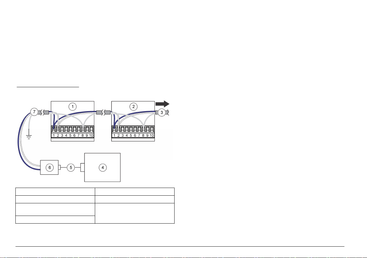
Installation des communications série
Reportez-vous à la Figure 8 à la page 34
pour connecter un instrument avec une communication série (RS485,
RS232 ou impulsion).
Câblage réseau
Jusqu'à 32 instruments (d'une charge de 12 K chacun) peuvent être
compris dans un réseau RS485 (EIA-485) avec communication FXB ou
RS485 Modbus. Utilisez des fils de catégorie supérieure pour des
communications série telles que Belden 9841. Le fabricant recommande
de ne pas avoir un réseau d'une longueur de plus de 1 200 m.
Un schéma de câblage réseau typique est représenté à la Figure 11.
Figure 11 Câblage réseau
1 Compteur de particules 5 Câble
2 Compteur de particules 6 Convertisseur RS232/RS485
3 Vers des compteurs de particule
supplémentaires
4 PC
et au Tableau 6 à la page 34
7 Câble réseau
Connexion au réseau Ethernet
Connectez
réseau 10Base-T ou 100Base-T Ethernet standard. Vérifiez que le
câblage est compatible avec la vitesse du réseau pour éviter tout
problème intermittent. Pour cet instrument, l'Ethernet standard 10Base-T
est suffisant pour transmettre les données et tolère mieux les erreurs
d'installation.
• Longueur : longueur de câble simple de 100 m maximum (des
répéteurs peuvent être utilisés pour augmenter la distance)
• Répéteurs : 4 (maximum)
• Type de connecteur : RJ45 (câblage standard Ethernet convention
T-568B)
instruments dotés d'une communication Ethernet à un
Branchement des sorties analogiques
Connectez les instruments à un système d'acquisition des données via
la fonctionnalité de sortie analogique. Reportez-vous à la Figure 8
à la page 34 et au Tableau 6 à la page 34 pour obtenir des informations
sur le câblage.
Lorsqu'une alimentation électrique 24 V CC est utilisée, l'alimentation
électrique peut également servir de source d'alimentation en boucle
4–20 mA si la sortie est suffisante pour la boucle. Voir Figure 12. La
Figure 13 montre la limite maximale de la résistance de ligne totale
( charge et câblage combinés) qui est autorisée.
Les instruments disposant de la fonctionnalité de sortie analogique
envoient un signal de 4 à 20 mA, proportionnel au nombre de
comptages pendant une durée d'échantillonnage donnée. Les sorties
analogiques sont mises à jour à la fin de chaque période
d'échantillonnage. Le système d'acquisition de données reçoit le signal.
Les instruments disposant de la fonctionnalité de sortie analogique
peuvent avoir deux ou quatre tailles de canaux. Les appareils
analogiques ne peuvent pas être utilisés dans une configuration réseau.
Utilisez le logiciel utilitaire de configuration pour configurer le nombre
maximum de comptages correspondant au signal de 20 mA. Voir
Configurer l'instrument à la page 39.
36 Français
Page 37

Après la mise sous tension, les sorties analogiques des canaux affichent
4 mA. Après la mise hors tension, lors d'un dysfonctionnement du
capteur ou d'un défaut de l'écoulement, la sortie analogique des canaux
est inférieure à 2 mA. Si un canal est désactivé par l'utilisateur, la sortie
du canal est inférieure à 2 mA. Tout signal inférieur à 4 mA (valeur de
comptage à zéro) génère un nombre négatif dans le système
d'acquisition des données, qui indique un problème au niveau du signal
provenant de l'
instrument.
Configurez le logiciel de surveillance centralisée afin qu'une alarme soit
émise pour tout signal inférieur à 4 mA (valeur de comptage à zéro), de
manière à obtenir une alarme de perte d'alimentation, d'écoulement ou
de capteur selon les besoins.
Figure 12 Configuration pour la puissance en boucle
1 Configuration pour l'alimentation
électrique commune en boucle
2 Configuration pour l'alimentation
électrique séparée en boucle
3 Alimentation électrique en boucle
24 VCC
4 + Alimentation boucle 8 + Alimentation
5 Commune
6 Système de recueil 4-20 mA
7 Alimentation électrique 24 VCC
Français 37
Page 38

Figure 13 Limite maximale pour un fonctionnement courant en
boucle
1 Tension d'alimentation de la boucle 3 En dehors de la plage de
2 Plage de fonctionnement
acceptable (au-delà de la ligne)
fonctionnement (en dessous de la
ligne)
4 Limite maximale de la résistance de
boucle totale
Mise en marche
Nettoyage des surfaces externes
A V I S
Ne vaporisez jamais de liquide ou de vapeur de peroxyde d'hydrogène (VHP)
directement sur l'
circuit d'écoulement ou dans le système électronique du compteur entraîne un
endommagement du capteur.
Empêchez les vapeurs de produits chimiques de désinfection de pénétrer dans
l'enveloppe de l'
l'instrument.
instrument. Toute introduction de solutions liquides dans le
instrument et d'entrer en contact avec le système électronique de
A V I S
Nettoyez les surfaces externes à l'aide d'un chiffon non pelucheux
imbibé d'isopropanol (IPA). La sonde d'échantillonnage (isocinétique)
peut être autoclavée pour le nettoyage.
Nettoyage des surfaces internes
Utilisez le filtre de comptage à zéro
(ex. particules, peluches ou poussière) des surfaces internes de
l'instrument et du tuyau d'entrée d'air. Lorsque le comptage atteint zéro,
les surfaces internes et le tuyau d'entrée d'air sont propres.
Eléments à rassembler : filtre de comptage à zéro
1. Fixez le filtre de comptage à zéro au tuyau d'arrivée d'air.
Le filtre de comptage à zéro empêche toute particule externe de
pénétrer dans l'instrument.
2. Démarrez le prélèvement d'échantillon et faites fonctionner
l'instrument pendant au moins 30 minutes. Voir Fonctionnement
manuel à la page 46.
3. Surveillez l'air de la salle à des intervalles de 5 minutes et continuez
jusqu'à ce que le comptage de particules atteigne 0–1.
Facultatif : pour enregistrer les données, réglez la durée de
l'échantillonnage : échantillonnage réglé sur 5 minutes. Voir
Configurer l'instrument à la page 39.
4. Si le comptage de particules n'atteint pas 0–1 après une dizaine
d'échantillonnages de 5 minutes, purgez l'instrument pendant la nuit.
Voir Purge de l'instrument à la page 38.
autre pour éliminer les contaminants
Purge de l'instrument
Procédez à une purge pour obtenir un nombre de particules compris
entre 0 et 1. La purge se fait habituellement avant un test, afin de veiller
à avoir une référence de base pour l'instrument.
1. Retirez environ 2,5 cm du tuyau d'arrivée d'air, au niveau de
l'extrémité de la sonde d'échantillonnage, afin de retirer toute section
étirée ou rayée.
2. Fixez le filtre de comptage à zéro autre au tuyau d'arrivée d'air.
38 Français
Page 39

3. Faites fonctionner l'
4. Si le comptage de particules n'affiche pas un nombre de 0 à 1 après
24 heures, vérifiez si la source de particules est le tuyau d'arrivée
d'air.
a. Installez le filtre de comptage à zéro directement sur le raccord
d'arrivée d'air.
b. Faites fonctionner l'instrument pendant 15 minutes
supplémentaires.
c. Surveillez l'air ambiant pendant 5 minutes et enregistrez les
résultats. Répétez cette étape jusqu'à quatre fois pour que le
comptage de particules finisse par afficher un nombre de 0 à
1 pendant un échantillonnage de 5 minutes.
d. Si un comptage de particules affiche un nombre de 0 à 1, cela
signifie que le tuyau d'arrivée d'air est la source des particules.
Remplacez le tuyau d'arrivée d'air.
e. Si le comptage de particules n'atteint pas un nombre de 0 à 1,
contactez l'assistance technique.
instrument pendant 24 heures.
Fonctionnement
Configuration
Pour procéder à la première configuration, branchez l'instrument à un
PC.
Si l'instrument a déjà été configuré une première fois, modifiez les
paramètres de configuration selon les besoins en le branchant
directement à un PC ou via une connexion ModbusTCP. Pour une
configuration via un réseau, seuls les réglages LAN peuvent être
changés. Voir Configuration des paramètres LAN via un réseau
à la page 42.
Connexion à un PC
Eléments à réunir :
• CD de l'utilitaire de configuration
• Câble du port de service
• PC fonctionnant sous Windows® 2000 Professional, Windows XP
Professional, Windows Vista (32 bits), Windows 7 (32 bits ou 64 bits
en mode d'émulation XP)
• Adaptateur USB-RS232 si le PC ne possède pas de port RS232
1. S'assurer que Microsoft .Net Framework est installé sur le PC. Sinon,
ouvrez le fichier dotnetfx.exe sur le CD de l'utilitaire de configuration
pour installer l'application.
Remarque : L'utilisateur doit être enregistré sur le PC comme administrateur.
2. Copiez et collez le fichier SetupUtility.exe depuis le CD de l'utilitaire
de configuration vers le PC.
3. Connectez le câble du port de service au port de service de
l'instrument et à un port COM du PC.
Configurer l'instrument
A l'aide de l'utilitaire de configuration, définissez les paramètres de
chaque instrument. Lorsque l'instrument est mis sous tension, il
recherche une nouvelle configuration. S'il ne trouve pas de nouvelle
configuration, il utilise la dernière configuration enregistrée.
1. Ouvrez le fichier SetupUtility.exe installé sur le PC pour démarrer le
programme de l'utilitaire de configuration.
2. Sélectionnez l'onglet Basic Setup (Configuration de base).
3. Accédez au champ Port dans la partie droite de la fenêtre.
Sélectionnez le port COM sur le PC auquel l'instrument est connecté.
4. Cliquer sur Read Instrument. L'utilitaire lit les données enregistrées
sur l'instrument.
5. Vérifiez que les données figurant dans la section Instrument
Information (Informations sur l'instrument) sont correctes (référence
du modèle, option de communication, version du micrologiciel et
adresse de communication, le cas échéant).
Français 39
Page 40

6. Dans la section General (Général), sélectionnez les paramètres.
Option Description
Mode de comptage Permet de définir le mode de comptage. N'a pas
Sample Timing: Sample
(Durée
d'échantillonnage :
échantillon)
Sample Timing: Hold
(Durée
d'échantillonnage :
maintien)
Cycles de comptage Définit le nombre d'échantillons prélevés avant
Slave Address/Location
ID (ID de
l'emplacement / Adresse
esclave)
Comm Timeout (Délai
d'expiration de la
communication)
d'incidence sur la sortie analogique des
appareils analogiques.
Différentiel : le comptage de particules affiché
pour chaque canal correspond au comptage lié
à chaque taille de canal.
Cumulatif (par défaut) : le comptage de
particules affiché pour chaque canal correspond
au comptage lié à chaque taille de canal et aux
tailles de canal plus importantes. Par exemple,
si la taille du canal est 0,3 µm, les particules de
0,3 µm ou d'une taille supérieure sont comprises
dans le comptage.
Définit la durée de chaque échantillon (par
défaut : 00:01:00 = 1 minute).
Définit la durée pendant laquelle la collecte des
données s'arrête une fois que les échantillons
sont prélevés (par défaut : 00:00:00).
l'arrêt de la collecte des données et le début du
temps de maintien (0 = échantillonnage continu).
Ne pas modifier (par défaut = 1).
Permet de définir le nombre de secondes entre
une interruption de la communication et
l'émission d'une alarme de communication
(Comm). Pour désactiver les alarmes de
communication, réglez ce délai sur 0. Pour les
instruments dotés de la fonction de sortie
analogique, réglez ce délai sur 0.
Option Description
Nom de l'emplacement Permet d'attribuer un identifiant unique à
System Date/Time
(Date / Heure du
système)
Moving Cumulative
Counts (Comptage
cumulatif mobile)
Store Partial Records
(Enregistrement des
données partielles)
Temp Units °C (Unités
de température °C)
LCD à distance Non disponible (désactivé)
Alarmes décompte Permet de définir le nombre minimum de
l'instrument.
Permet de définir la date (AAAA/MM/JJ) et
l'heure (HH:MM:SS, format 24 heures).
Permet de définir le nombre d'échantillons pour
le canal 1 ou le canal 2, qui s'additionnent et
s'affichent dans les canaux 3 et 4. Le
canal 3 affiche le comptage cumulatif du canal 1.
Le canal 4 affiche le comptage cumulatif du
canal 2.
Permet d'enregistrer les données
d'échantillonnage partielles dans le tampon. Les
données d'échantillonnage partielles
correspondent à un échantillonnage qui s'est
interrompu avant la fin.
Permet de sélectionner les degrés Fahrenheit
(par défaut) ou Celsius comme unités de
température.
particules pour chaque canal qui déclenche une
alarme de comptage.
Pour consulter la taille des canaux, sélectionnez
l'onglet Data Display (Affichage des données).
Voir Figure 15 à la page 46.
40 Français
Page 41

Option Description
Mode d'échantillonnage Permet de définir le mode d'échantillonnage.
Unités de débit Permet de définir l'unité de débit d'air. Options :
Auto : la collecte des données d'échantillonnage
démarre automatiquement lorsque l'instrument
est mis sous tension.
Manuel : la collecte des données
d'échantillonnage ne démarre pas
automatiquement lorsque l'instrument est mis
sous tension. La collecte des données
d'échantillonnage doit être démarrée
manuellement. Voir Fonctionnement manuel
à la page 46.
Remarque : Les appareils Ethernet avec sortie
analogique ne peuvent pas être définis sur le
mode manuel car il n'y a pas de communication
bi-directionnelle avec le logiciel de surveillance
centralisée sur ces appareils. Ces appareils
doivent toujours être démarrés en mode Auto.
CFM (pieds cubes par minute) ou LPM (litres par
minute).
7. Si une colonne lumineuse externe fournie en option est connectée à
l'instrument
, utilisez la section Diagnostics pour attribuer le
clignotement ou la lumière fixe à l'une des couleurs des voyants pour
indiquer que le câblage est correct.
Remarque : Il n'est pas possible de sauvegarder les réglages de diagnostic et
n'ont aucun effet sur le fonctionnement de l'instrument.
8. Pour les appareils avec sortie analogique, modifiez les paramètres
de la sortie analogique 4–20 mA dans la section Analog
(Analogique).
Option Description
Pleine
échelle
Output
State (Etat
de sortie)
Permet de définir le comptage de particules pour chaque
canal qui correspond à un signal de sortie 20 mA (par défaut =
1 000). Un comptage de particules de zéro correspond à un
signal de sortie 4 mA.
Remarque : Les alarmes de comptage ne sont pas reportées
dans le logiciel de surveillance centralisée. Configurez le
logiciel de surveillance centralisée pour déclencher les
alarmes de comptage selon vos besoins.
Permet de définir l'état de la sortie. Réglez la sortie sur
Normal pour un fonctionnement normal.
Zéro : maintient la sortie à 4 mA.
Span : maintient la sortie à 20 mA.
9. Pour la communication série (unités RS485 uniquement), modifiez le
paramètre de communication dans la section Serial (Série). Options :
FXB, Modbus, compatibilité R48XX, FXB1. Si le Modbus est
sélectionné, entrer l'adresse esclave. Quand l'adresse est 31 ou
moins, utilisez les commutateurs DIP sous l'instrument pour régler
l'adresse. Reportez-vous à la section Sortie série RS485 avec
protocole Modbus RTU à la page
Remarque : Si une adresse de 32 ou plus est entrée, le réglage du
commutateur DIP est ignoré et la valeur entrée est utilisée.
44.
10. Pour la communication par impulsions (unités RS485 uniquement),
sélectionnez la taille de canal pour la sortie d'impulsions du
canal 2 dans la section Pulse (Impulsions) (par défaut : canal de
comptage 2). La sortie d'impulsions du canal 1 correspond toujours à
la taille de particule du canal 1.
11. Pour la communication Ethernet (unités Ethernet uniquement),
reportez-vous à la section Configuration des paramètres Ethernet
à la page 42.
12. Cliquez sur Save Settings (Enregistrer les paramètres) pour
enregistrer les modifications.
Français 41
Page 42

Configuration des paramètres Ethernet
1. Pour les appareils Ethernet
sans la fonction de sortie analogique,
modifiez les paramètres Ethernet dans la section Ethernet. Les
paramètres Ethernet doivent être modifiés uniquement par un
spécialiste en réseaux.
Option Description
MAC Contrôle d'accès média : affiche l'adresse permanente
DHCP/APIPA Active ou désactive l'adresse IP statique ou dynamique
Adresse IP Pour les adresses IP, chaque instrument de base LAN
Masque sous
réseau
Port serveur Port d'écoute du serveur Modbus TCP (par défaut :
Port client Indisponible (désactivé)
Passerelle Routeur ou point d'accès vers un autre réseau (par
unique du matériel (lecture seule)
en connexion au serveur DHCP (par défaut : désactivé).
Lorsque l'option est activée, l'instrument obtient une
adresse IP et un masque de sous-réseau
automatiquement lors de la mise sous tension.
Si un serveur DHCP n'est pas disponible, l'instrument
utilise APIPA pour obtenir une adresse IP et un masque
de sous-réseau.
• Plage d'adresse IP APIPA : 169.254.0.0 à
169.254.255.255
• Masque de sous-réseau : 255.255.0.0 (réseau de
Classe B)
doit posséder une adresse IP unique. Plage :
169.254.0.0 à 169.254.255.255 (par défaut :
169.254.1.2).
Les instruments de même type qui communiquent avec
un prologiciel unique (ex. : FMS) utilisent le même
masque de sous-réseau (par défaut : 255.255.0.0).
Gamme: 0 à 255, seulement un nombre entier.
502). Gamme: 0 à 65535, seulement un nombre entier.
défaut : 169.254.1.5)
Option Description
Serveur IP à
distance
Protocole
Ethernet
Indisponible (désactivé)
Définit le protocole Ethernet sur Modbus ou FXB.
2. Pour les unités Ethernet avec la fonction de sortie analogique,
reportez-vous à la section Configuration des paramètres LAN via un
réseau à la page 42 pour définir les paramètres Ethernet.
3. Cliquez sur Save Settings (Enregistrer les paramètres) pour
enregistrer les modifications.
Configuration des paramètres LAN via un réseau
1. Dans l'utilitaire de configuration, sélectionnez l'onglet LAN Setup
(Configuration LAN). Le logiciel recherche les instruments LAN. Les
instruments LAN trouvés s'affichent.
2. Sélectionnez un instrument pour afficher les paramètres de
l'instrument LAN.
3. Modifiez les paramètres LAN. Reportez-vous au tableau des options
à la section Configuration des paramètres Ethernet à la page
42.
4. Cliquez sur Save Settings (Enregistrer les paramètres) pour
enregistrer les modifications.
Test des sorties analogiques
Pour les instruments dotés de la fonctionnalité de sortie analogique,
réalisez un test sur les sorties analogiques.
1. Connectez les sorties analogiques aux résistances de charge du
système d'acquisition des données.
Remarque : Vous pouvez également installez un jeu de résistances de charge
d'une précision de 0,1 % et d'une capacité minimale de 0,25 W sur la sortie
42 Français
Page 43

analogique. Les valeurs de résistance de charge généralement utilisées sont
100, 250 ou 500 ohms.
2. Laissez une minuscule quantité de particules s'écouler à travers
l'instrument pour obtenir un comptage dans le canal de test.
Remarque : Une méthode utilisée pour générer ces comptages consiste à
utiliser un filtre de comptage à zéro et de faire un trou d'épingle dans la
tuyauterie qui se trouve entre le filtre et l'instrument.
3. Depuis l'onglet Basic Setup (Configuration de base) de l'utilitaire de
configuration, définissez provisoirement les paramètres suivants :
• Cycles de comptage—1
• Durée d'échantillonnage : maintien—10 secondes minimum
4. Cliquez sur Save Settings (Enregistrer les paramètres).
5. Sélectionnez l'onglet Data Display (Affichage des données), puis
cliquez sur Monitor (Surveillance) si cette option est affichée, de
sorte à ce que les données affichées soient mises à jour en continu à
chaque prélèvement d'échantillon.
6. Cliquez sur Sample (Echantillon) si cette option est affichée, pour
démarrer la collecte des échantillons.
7. Lorsque la valeur de l'état passe de « Count » (Comptage) à
« Stop » (Arrêt), mesurez la tension des résistances de charge pour
chaque canal. Noter aussi les comptages indiqués dans l'affichage
pour chaque canal.
8. Calculez la tension attendue d'après les comptages affichés à l'aide
de l'équation suivante. S'assurer que les tensions calculées et
mesurées concordent.
Tension = (((SC ÷ FC × 16) + 4) ÷ 1 000) × RL
Où :
SC = comptage d'échantillons à la fin de la durée d'échantillonnage
FC = comptage des canaux à échelle réelle. Reportez-vous aux
paramètres analogiques dans l'utilitaire de configuration.
RL = valeur de la résistance de charge en ohms
La tension de sortie prévue quand le comptage du canal à déviation
maximale est 1 000 avec une résistance de 100,250 et 500 ohms est
présentée au Tableau 7.
9. Pour refaire le test, reportez-vous aux étapes 7–8.
10. Pour les unités avec une surveillance de l'écoulement, enlevez
temporairement la centrale à vide de l'
instrument.
11. Pendant l'émission de l'alarme de débit, mesurez la tension des
résistances de charge pour chaque canal.
12. Calculez la tension attendue à l'aide de l'équation suivante. S'assurer
que les tensions calculées et mesurées concordent.
Tension = < (0,002 × RL)
Où : RL = valeur de la résistance de charge en ohms
Exemple : pour une résistance de 100 ohms, la tension doit être
inférieure à 0,20 V.
13. Depuis l'onglet Basic Setup (Configuration de base), redéfinissez les
paramètres sur les valeurs précédentes.
14. Cliquez sur Save Settings (Enregistrer les paramètres).
Tableau 7 Tension de sortie avec des résistances de 100, 250 et
500 ohms
Compteur
d'échantillonnage
0 0,40 V 1,00 V 2,00 V
100 0,56 V 1,40 V 2,80 V
200 0,72 V 1,80 V 3,60 V
300 0,88 V 2,20 V 4,40 V
400 1,04 V 2,60 V 5,20 V
500 1,20 V 3,00 V 6,00 V
600 1,36 V 3,40 V 6,80 V
700 1,52 V 3,80 V 7,60 V
800 1,68 V 4,20 V 8,40 V
900 1,84 V 4,60 V 9,20 V
1 000 2,00 V 5,00 V 10,00 V
100 Ω 250 Ω 500 Ω
Français 43
Page 44

Sortie série RS485 avec protocole Modbus RTU
Les instruments dotés de l'option de communication RS485 Modbus
utilisent le protocole Modbus RTU standard. Dans ce mode de
communication, des séries de registres stockent les données sur les
mesures des paramètres de fonctionnement et de résultat.
Lorsqu'une connexion Modbus TCP est établie, l'utilisateur peut utiliser
toutes les options de configuration des registres Modbus. Consultez le
site web de l'entreprise pour accéder aux registres Modbus. Ecrivez les
pilotes pour communiquer avec l'
l'aide du protocole Modbus RTU.
Le circuit en réseau série RS485 assure les communications pour un
maximum de 32 instruments et un ordinateur de contrôle. Seul un
instrument à la fois peut transmettre les données. Chaque instrument
doit posséder une adresse instrument unique.
1. Retournez l'instrument. Le commutateur DIP est sur le dessous de
l'instrument.
2. Modifiez la configuration du commutateur DIP en sélectionnant une
adresse réseau unique pour l'instrument. Voir Tableau 8.
Remarque : L'adresse 0 ne peut être seulement utilisée qu'avec un protocole
FXB. L'adresse 0 est réservée pour l'utilisation comme adresse générale pour
Modbus RTU. Si l'adresse 0 est réglée avec le protocole Modbus, l'instrument
utilisera l'adresse 1.
Tableau 8 Configuration du commutateur DIP pour l'adresse
Adresse
réseau
0 Arrêt Arrêt Arrêt Arrêt Arrêt
1 Marche Arrêt Arrêt Arrêt Arrêt
2 Arrêt Marche Arrêt Arrêt Arrêt
3 Marche Marche Arrêt Arrêt Arrêt
4 Arrêt Arrêt Marche Arrêt Arrêt
5 Marche Arrêt Marche Arrêt Arrêt
Commutateur 1
instrument à travers ces registres à
réseau
Commutateur 2
Commutateur 3
Commutateur 4
Commutateur 5
Tableau 8 Configuration du commutateur DIP pour l'adresse
réseau
(suite)
Adresse
réseau
6 Arrêt Marche Marche Arrêt Arrêt
7 Marche Marche Marche Arrêt Arrêt
8 Arrêt Arrêt Arrêt Marche Arrêt
9 Marche Arrêt Arrêt Marche Arrêt
10 Arrêt Marche Arrêt Marche Arrêt
11 Marche Marche Arrêt Marche Arrêt
12 Arrêt Arrêt Marche Marche Arrêt
13 Marche Arrêt Marche Marche Arrêt
14 Arrêt Marche Marche Marche Arrêt
15 Marche Marche Marche Marche Arrêt
16 Arrêt Arrêt Arrêt Arrêt Marche
17 Marche Arrêt Arrêt Arrêt Marche
18 Arrêt Marche Arrêt Arrêt Marche
19 Marche Marche Arrêt Arrêt Marche
20 Arrêt Arrêt Marche Arrêt Marche
21 Marche Arrêt Marche Arrêt Marche
22 Arrêt Marche Marche Arrêt Marche
23 Marche Marche Marche Arrêt Marche
24 Arrêt Arrêt Arrêt Marche Marche
25 Marche Arrêt Arrêt Marche Marche
26 Arrêt Marche Arrêt Marche Marche
27 Marche Marche Arrêt Marche Marche
Commutateur 1
Commutateur 2
Commutateur 3
Commutateur 4
Commutateur 5
44 Français
Page 45

Tableau 8 Configuration du commutateur DIP pour l'adresse
réseau
(suite)
Adresse
réseau
28 Arrêt Arrêt Marche Marche Marche
29 Marche Arrêt Marche Marche Marche
30 Arrêt Marche Marche Marche Marche
31 Marche Marche Marche Marche Marche
Commutateur 1
Commutateur 2
Commutateur 3
Commutateur 4
Commutateur 5
Sortie série RS485 avec protocole FXB
Les instruments dotés de l'option de communication RS485 FXB utilisent
le protocole FXB standard. Consultez le site web de l'entreprise pour en
savoir plus sur le protocole FXB.
Communication par impulsions
Les instruments dotés de l'option de communication par impulsions
envoient un signal d'impulsion de 8 µs lorsqu'une particule est détectée.
Voir Figure 14. Un compteur d'impulsions externe ou un système
d'acquisition des données reçoit le signal d'impulsion et compte les
impulsions comme des particules.
Les instruments dotés de la communication par impulsions ont deux
canaux de sortie d'impulsions (canal 1 et canal 2). Le canal 1 envoie un
signal d'impulsion à chaque fois que la taille de particule associée au
canal 1 est détectée. Le canal 2 envoie un signe d'impulsion à chaque
fois que la taille du canal sélectionnée par l'utilisateur est détectée.
La communication par impulsions comprend un signal de sortie d'état
allant de bas à élevé lorsqu'une alarme est active. La communication
par impulsions ne peut pas être utilisée dans une configuration réseau.
Définissez l'adresse réseau des
impulsions sur 1. Voir Tableau 8 à la page 44.
instruments à communication par
Le signal d'impulsion peut être envoyé au moyen de l'un des deux
modes de comptage :
• Mode différentiel (par défaut) : un signal est envoyé sur le
canal 1 lorsqu'une particule a une taille comprise entre le seuil de
taille du premier et du deuxième canal. Un signal est envoyé sur le
canal 2 lorsqu'une particule est plus grande que le seuil de taille de
canal sélectionné par l'utilisateur.
• Mode cumulé : un signal est envoyé sur le canal 1 lorsqu'une
particule a une taille qui dépasse le seuil de taille du premier ou du
second canal. Un signal est envoyé sur le canal 2 lorsqu'une particule
est plus grande que le seuil de taille de canal sélectionné par
l'utilisateur.
Figure 14 Exemple pour illustrer la différence entre le mode de
comptage différentiel et le mode cumulatif
1 Signal d'impulsion envoyé depuis le
compteur
2 Transfert des données en mode
différentiel et en mode cumulatif
3 Canal 2 6 Comptage cumulé - trois particules
4 Canal 1
5 Comptage différentiel - une
particule 0,3 µm et deux 5,0 µm
0,3 µm et deux 5,0 µm
Français 45
Page 46

Fonctionnement manuel
Utilisez l'utilitaire de configuration via une connexion directe au PC ou
une connexion LAN pour utiliser l'
1. Ouvrez le fichier SetupUtility.exe pour lancer l'utilitaire de
configuration.
2. Sélectionnez l'onglet Data Display (Affichage des données).
Reportez-vous à la Figure 15 pour obtenir une description des
données affichées.
3. Utilisez les boutons pour faire fonctionner l'instrument.
Remarque : Les boutons varient en fonction de l'état du système.
Option Description
Monitor (Surveillance) Affiche les données mises à jour en continu en
Stop Monitor (Arrêt de la
surveillance)
Echantillon Permet de démarrer la collecte d'échantillons.
Stop Count (Arrêt du
comptage)
Mode actif Active le laser interne . Active les alarmes.
Inactive Mode (Mode
inactif)
Display Buffered Data
(Affichage des données
en mémoire tampon)
Download Buffer
(Charger la mémoire
tampon)
Effacer la mémoire
tampon
instrument en mode manuel.
temps réel.
Interrompt la modification des données
affichées.
Les échantillons sont prélevés selon les
paramètres définis dans l'onglet Basic Setup
(Configuration de base). Si l'instrument est en
mode inactif, il passe en mode actif.
Arrête la collecte d'échantillons.
Désactive le laser interne . Désactive les
alarmes.
Affiche les données du dernier échantillon
prélevé. Se met à jour après chaque
échantillonnage.
Enregistre les données de la mémoire tampon
sur le PC dans un fichier texte (CSV).
Efface toutes les données enregistrées dans la
mémoire tampon.
Figure 15 Affichage des données en temps réel
1 Alarmes actives (capteur, débit,
comm, comptage1)
2 Tailles des canaux et comptage des
particules
3 Sample time (Durée
d'échantillonnage)
4 Heure et date de démarrage du
dernier échantillon
5 Etat du système 11 Tension Cal : évalue la propreté
6 Service technique uniquement
1
Lorsqu'une alarme de comptage est déclenchée, le comptage élevé de
particules s'affiche en rouge.
7 Débit d'air (cfm ou l/min)
8 Volume d'air collecté pour
l'échantillon (cfm ou l/min)
9 Valeurs du capteur de température
et d'humidité relative (RH) fourni en
option
10 Indisponible
du verre du capteur
46 Français
Page 47

Etalonnage
L'
instrument ne peut pas être étalonné par l'utilisateur. Contactez le
fabricant pour l'étalonnage de l'instrument.
Maintenance
A T T E N T I O N
Risque de blessures corporelles Seul le personnel qualifié est autorisé à
entreprendre les opérations décrites dans cette section du manuel.
Ne pas démonter l'appareil pour entretien. Si les composants internes doivent
être nettoyés ou réparés, contactez le fabricant.
Calendrier d'entretien
Le Tableau 9 présente le calendrier recommandé pour les tâches
d'entretien. Les exigences du site comme les conditions d'utilisation
peuvent augmenter la fréquence de certaines tâches.
Tableau 9 Calendrier d'entretien
Tâche 1 an
Remplacement du tuyau d'arrivée à la page
Etalonnage à la page 47 X
Remplacement du tuyau d'arrivée
Remplacez régulièrement le tuyau d'arrivée d'air pour éviter tout risque
de dépôt de matières organiques ou de contamination de particules
inorganiques sur les parois du tuyau. Une telle contamination risque de
fausser le comptage en augmentant le nombre de particules.
Le fabricant recommande de remplacer au moins une fois par an la
tuyauterie d'arrivée d'air des installations FMS classiques dans les salles
blanches des sites dédiés aux sciences de la vie et à l'industrie
pharmaceutique.
A V I S
47 X
Français 47
Page 48

Tabla de contenidos
Especificaciones en la página 48 Puesta en marcha en la página 62
Información general en la página 49 Operación en la página 63
Instalación en la página 54 Mantenimiento en la página 71
Especificaciones
Las especificaciones están sujetas a cambios sin previo aviso.
Especificación Detalles
Dimensiones (An x Pr x
Al)
Carcasa Acero inoxidable 304
Fuente de luz Diodo Laser™ de larga vida, láser de clase 3B
Peso 0,82 kg (1,8 libras)
Grado de
contaminación
Tipo de instalación I
Clase de protección III
Requisitos de
alimentación
Consumo energético
(máximo)
Temperatura de
funcionamiento
Temperatura de
almacenamiento
Humedad Funcionamiento y almacenamiento: del 5 al 95 % de
Altitud 2.000 m (6.562 pies) máximo
13.56 x 8.93 x 12.06 cm (5.34 x 3.52 x 4.75 pulg.)
2
9–28 VCC (fuente: energía limitada de Clase 2, <
150 VA)
Unidades en serie y de impulsos: 3,3 W; Unidad
Ethernet: 4,3 W; Unidad analógica: 3,5 W; 1 A como
máximo
De 5 a 40 °C (de 40 a 104 °F); mejor rendimiento: de
10 a 32 °C (de 50 a 90 °F)
De –40 a 70 °C (–40 a 158 °F)
humedad relativa, sin condensación
Especificación Detalles
Tamaños de puertos Modelos 6003 y 6005: conexión para tubo de entrada
Opciones de señal de
salida
Almacenamiento de
datos
Caudal de la muestra Modelos 6003 y 6005: 0,1 cfm (2,83 l/m) ± 5 %
Presión de entrada Ambiente a vacío de 2,5 mm (0,1 pulg.) Hg
Requisito de vacío Vacío de ≥ 406 mm (16 pulg.) Hg (542 mbar) como
Rango Modelo 6003: de 0,3 μm a 10,0 μm a 0,1 cfm
Sensibilidad Modelo 6003: 0,3 μm a 0,1 cfm (2,83 l/min)
Eficiencia del recuento Modelo 6003: del 50 % (± 20 %) para 0,3 μm, (del
con DI de 0,32 cm (0,12 pulg.), tubo de salida con DI
de 0,64 cm (0,25 pulg.)
Modelos 6013 y 6015: conexión para tubo de entrada
con DI de 0,64 cm (0,25 pulg.), tubo de salida con DI
de 0,64 cm (0,25 pulg.)
Impulso, analógica de 4–20 mA, RS232 en serie con
protocolo de comunicación Modbus RTU o FXB (sin
red), RS485 en serie con protocolo de comunicación
Modbus RTU o FXB, Ethernet con protocolo
ModbusTCP
1.000 muestras/registros (los registros más antiguos
se sobrescriben cuando el búfer está lleno)
Modelos 6013 y 6015: 1,0 cfm (28,3 l/m) ± 5 %
mínimo medido en cada instrumento con caudal por
todos los instrumentos.
(2,83 l/min)
Modelo 6005: de 0,5 μm a 10,0 μm a 0,1 cfm
(2,83 l/min)
Modelos 6013 y 6015: de 0,5 μm a 10,0 μm a 1,0 cfm
(28,3 l/min)
Modelo 6005: 0,5 μm a 0.1 cfm (2,83 l/min)
Modelo 6013: 0,3 μm a 1,0 cfm (28,3 l/min)
Modelo 6015: 0,5 μm a 1,0 cfm (28,3 l/min)
100 % ± 10 % 1,5 veces la sensibilidad mínima)1.
Modelos 6005, 6013 y 6015: del 50 % (± 20 %) para
0,5 μm, (del 100 % ± 10 % 1,5 veces la sensibilidad
mínima)1.
48 Español
Page 49

Especificación Detalles
Pérdida de fiabilidad Modelo 6003 y 6005 (todas las opciones de salida):
Tasa de recuento falso Uno o menos en 5 minutos
Certificaciones CE
1
Totalmente conforme con ISO21501-4.
del 10 % a 140.000.000 partículas/m
(4.000.000 partículas/pies3)
Modelo 6013 y 6015 (todas las opciones, excepto
impulsos): del 10 % a 20.000.000 partículas/m
(566.000 partículas/pies3)
3
3
Asegúrese de que la protección proporcionada por el equipo no está
dañada. No utilice ni instale este equipo de manera distinta a lo
especificado en este manual.
Uso de la información sobre riesgos
P E L I G R O
Indica una situación potencial o de riesgo inminente que, de no evitarse,
provocará la muerte o lesiones graves.
A D V E R T E N C I A
Indica una situación potencial o inminentemente peligrosa que, de no evitarse,
podría provocar la muerte o lesiones graves.
Información general
En ningún caso el fabricante será responsable de ningún daño directo,
indirecto, especial, accidental o resultante de un defecto u omisión en
este manual. El fabricante se reserva el derecho a modificar este
manual y los productos que describen en cualquier momento, sin aviso
ni obligación. Las ediciones revisadas se encuentran en la página web
del fabricante.
Versión ampliada del manual
Para obtener más información, consulte en el CD la versión ampliada de
este manual.
Información de seguridad
A V I S O
El fabricante no es responsable de ningún daño debo a un mal uso de este
producto incluyendo, sin limitación, daños directos, fortuitos o circunstanciales y
reclamos sobre los daños que no estén recogidos en la legislación vigente. El
usuario es el responsable de la identificación de los riesgos críticos y de tener los
mecanismos adecuados de protección de los procesos en caso de un posible
mal funcionamiento del equipo.
Lea todo el manual antes de desembalar, instalar o trabajar con este
equipo. Ponga atención a todas las advertencias y avisos de peligro. El
no hacerlo puede provocar heridas graves al usuario o daños al equipo.
P R E C A U C I Ó N
Indica una situación potencialmente peligrosa que podría provocar una lesión
menor o moderada.
Indica una situación que, si no se evita, puede provocar daños en el instrumento.
Información que requiere especial énfasis.
A V I S O
Etiquetas de precaución
Lea todas las etiquetas y rótulos adheridos al instrumento. En caso
contrario, podrían producirse heridas personales o daños en el
instrumento. Cada símbolo que aparezca en el instrumento se
comentará en el manual con una indicación de precaución.
Este símbolo (en caso de estar colocado en el equipo) hace
referencia a las instrucciones de uso o a la información de seguridad
del manual.
Este símbolo, cuando está en la caja o barrera de un producto, indica
que hay riesgo de descarga eléctrica o electrocución.
Español 49
Page 50

Este símbolo indica que en el equipo se utiliza un dispositivo láser.
El equipo eléctrico marcado con este símbolo no se podrá desechar
por medio de los sistemas europeos públicos de eliminación después
del 12 de agosto de 2005. De acuerdo con las regulaciones locales y
nacionales europeas (Directiva UE 2002/96/EC), ahora los usuarios
de equipos eléctricos en Europa deben devolver los equipos viejos o
que hayan alcanzado el término de su vida útil al fabricante para su
eliminación sin cargo para el usuario.
Nota: Para devolver los equipos para su reciclaje, póngase en contacto con el
fabricante o distribuidor para obtener instrucciones acerca de cómo devolver
equipos que han alcanzado el término de su vida útil, accesorios eléctricos
suministrados por el fabricante y todo elemento auxiliar, para su eliminación.
Información de seguridad del láser
Este instrumento es un PRODUCTO LÁSER DE CLASE 1, N. º de
registro de CDRH 9022243-029. Radiación láser invisible cuando está
abierto. Evite la exposición directa al haz. El mantenimiento de los
componentes internos solo debe realizarlo personal autorizado por el
fabricante.
El instrumento cumple la normativa IEC/EN 60825-1 y 21 CFR 1040.10,
excepto para las desviaciones de conformidad con el Laser Notice n. º
50, con fecha del 24 de junio de 2007.
Certificación
Reglamentación canadiense sobre equipos que provocan
interferencia, IECS-003, Clase A
Registros de pruebas de control del fabricante.
Este aparato digital de clase A cumple con todos los requerimientos de
las reglamentaciones canadienses para equipos que producen
interferencias.
Cet appareil numèrique de classe A répond à toutes les exigences de la
réglementation canadienne sur les équipements provoquant des
interférences.
FCC Parte 15, Límites Clase "A"
Registros de pruebas de control del fabricante. Este dispositivo cumple
con la Parte 15 de las normas de la FCC estadounidense. Su operación
está sujeta a las siguientes dos condiciones:
1. El equipo no puede causar interferencias perjudiciales.
2. Este equipo debe aceptar cualquier interferencia recibida, incluyendo
las interferencias que pueden causar un funcionamiento no deseado.
Los cambios o modificaciones a este equipo que no hayan sido
aprobados por la parte responsable podrían anular el permiso del
usuario para operar el equipo. Este equipo ha sido probado y
encontrado que cumple con los límites para un dispositivo digital Clase
A, de acuerdo con la Parte 15 de las Reglas FCC. Estos límites están
diseñados para proporcionar una protección razonable contra las
interferencias perjudiciales cuando el equipo está operando en un
entorno comercial. Este equipo genera, utiliza y puede irradiar energía
de radio frecuencia, y si no es instalado y utilizado de acuerdo con el
manual de instrucciones, puede causar una interferencia dañina a las
radio comunicaciones. La operación de este equipo en un área
residencial es probable que produzca interferencia dañina, en cuyo caso
el usuario será requerido para corregir la interferencia bajo su propio
cargo. Pueden utilizarse las siguientes técnicas para reducir los
problemas de interferencia:
1. Desconecte el equipo de su fuente de alimentación para verificar si
éste es o no la fuente de la interferencia.
2. Si el equipo está conectado a la misma toma eléctrica que el
dispositivo que experimenta la interferencia, conecte el equipo a otra
toma eléctrica.
3. Aleje el equipo del dispositivo que está recibiendo la interferencia.
4. Cambie la posición de la antena del dispositivo que recibe la
interferencia.
5. Trate combinaciones de las opciones descritas.
Descripción general del producto
instrumento cuenta partículas de aire con una fuente de luz de
Este
diodo láser y unos elementos ópticos de recogida. Consulte la Figura 1.
El aire de la sala atraviesa el contador de partículas mediante un
sistema de vacío externo conectado.
50 Español
Page 51

Pueden instalarse varios instrumentos en diferentes ubicaciones de una
sala limpia para controlar la calidad del aire. Los datos del recuento se
envían al software de control central suministrado por el usuario a través
de los protocolos de comunicación correspondientes. El software de
control central se utiliza para operar el
instrumento de forma remota.
La ruta del flujo del sensor es resistente al vapor de peróxido de
hidrógeno (VHP) para ciclos de limpieza y desinfección de salas limpias
estándar basados en VHP.
Figura 1 Descripción general del producto
1 Conector de comunicación y
entrada de alimentación,
10 patillas
1
2 Conexión de fuente de vacío (o
conexión rápida)
3 Conexión de entrada de aire de
muestra
7 Puerto del sensor de temperatura y
humedad relativa (HR)
8 Conexión de fuente de vacío
(ubicación alternativa)
9 Luces del indicador de conexión
(Tabla 2)
4 Luz indicadora de estado (Tabla 1) 10 Conector Ethernet RJ45
5 Puerto de servicio y puerto de pila
de luces opcional
6 Interruptor DIP, dirección de red
1
Todas las unidades excepto Ethernet
2
Solo unidades Ethernet
11 Conector de entrada de
alimentación, 5 patillas
1
2
2
2
Español 51
Page 52

Tabla 1 Luz indicadora de estado
Color Indicación Estado del sistema
Verde Parpadeo (3 segundos) Normal, muestreo
Encendido Normal, sin muestreo
Azul Encendido Fallo del sensor
Un parpadeo corto, un
parpadeo largo
Parpadeando Fallo de comunicación
Rojo Encendido o parpadeando Alarma de recuento
Amarillo Encendido Inicialización
Parpadeando Alerta de recuento
Morado Parpadeando Se están utilizando las herramientas
1
El software de control central suministrado por el usuario se puede utilizar
para que la luz amarilla parpadee cuando se produzca una alerta de recuento
con el protocolo ModBus, pero no con el protocolo FX. Los ajustes de las
alertas de recuento se seleccionan en el software de control central.
Fallo del flujo de aire
1
de configuración
Tabla 2 Luces indicadoras Ethernet
Color Indicación Estado
Amarillo Encendido Conectado
Verde Apagado 10Base-T
Encendido 100Base-T
Sonda isocinética
Para obtener la mejor precisión en entornos de flujo laminar, utilice
siempre la sonda isocinética suministrada con este
velocidad del aire en la sonda es similar a la velocidad de un entorno de
flujo laminar vertical u horizontal típico, como una sala limpia o una
campana limpia. La sonda isocinética suministrada ofrece la misma
velocidad de flujo vertical (u horizontal) del aire con el objeto de recoger
instrumento. La
muestras representativas del flujo laminar de la sala limpia para el
instrumento. Consulte la Figura 2 para obtener una comparación del
muestreo con y sin la sonda isocinética.
Figura 2 Función de la sonda isocinética
1 Sin sonda en flujo de aire no
laminar
2 Al contador de partículas 4 Sonda isocinética en flujo de aire
3 Sin sonda en flujo de aire laminar:
faltan partículas.
laminar: mayor precisión.
Configuraciones del instrumento
Este instrumento está disponible en varias configuraciones. Cada
configuración tiene un número de referencia diferente. En la Figura 3 se
muestra la estructura de los números de referencia. La Tabla 3 incluye
descripciones de los códigos de números de referencia.
52 Español
Page 53

Figura 3 Estructura del número de referencia
1 Caudal 3 Ubicación de escape 5 Comunicación
2 Sensibilidad (mínima) 4 Medición de caudal
Tabla 3 Códigos de parámetros
Parámetro Código Descripción Parámetro Código Descripción
Caudal 0 0,1 cfm
(para una
sensibilidad
de 0,3 µm y
0,5 µm)
1 1,0 cfm
(solo para
una
sensibilidad
de 0,5 µm)
Medición de
caudal
F Con
medición de
caudal
N Sin medición
de caudal
Tabla 3 Códigos de parámetros (continúa)
Parámetro Código Descripción Parámetro Código Descripción
Sensibilidad
(mínima)
Ubicación
de escape
Ejemplo: Un instrumento con un caudal de 0,1 cfm, una sensibilidad de 0,5 μm,
un puerto de escape inferior, medición de caudal y comunicación RS485 tendrá
los números de referencia 2088605-DF-S y 20888600-485. El segundo número
de referencia es necesario para identificar el tipo de comunicación en serie
(RS232 = 20888600-232, RS485 = 20888600-485 o Impulso = 20888600-PLS).
El segundo número de referencia no es necesario para los demás tipos de
comunicación.
3 0,3 µm Comunicación E Ethernet
5 0,5 µm S Opciones de
D Abajo (parte
inferior)
S Lateral
A Analógica
E/S en serie
Componentes del producto
Asegúrese de haber recibido todos los componentes. Consulte la
Figura 4. Si faltan artículos o están dañados, póngase en contacto con
el fabricante o el representante de ventas inmediatamente.
Español 53
Page 54

Figura 4 Componentes del instrumento
1 Contador de partículas de la serie
MET ONE 6000
2 Sonda para muestreo (isocinética)
3 Sonda para muestreo (isocinética)
4 Kit de montaje en barra DIN 8 Cable de puerto de servicio
1
2
3
4
5
1
con tubo
2
con tubo
Solo unidades de 1,0 cfm
Solo unidades de 0,1 cfm
Todas las unidades excepto Ethernet
Solo Ethernet
Solo se suministra un cable de puerto de servicio por pedido.
5 Conector de 10 patillas con
6 Conector de 5 patillas con carcasa
7 CD de herramientas de
3
carcasa
configuración
(conector DIN de 8 a conector en
serie de 9 patillas)
5
Instalación
Instrucciones de instalación
A V I S O
Antes de comenzar el ciclo de limpieza o desinfección, detenga la bomba de
vacío y cubra la conexión de entrada de aire.
Unas temperaturas internas elevadas pueden causar daños en los componentes
del instrumento.
• Instale el instrumento en interiores en una ubicación limpia, seca, bien
ventilada y con temperatura controlada con un nivel de vibración
mínimo.
•
Si la sala se limpia con regularidad, instale el instrumento fuera de la
sala. De esta forma, solo el de entrada de aire y los tubos de vacío
estarán dentro de la sala limpia. De forma alternativa, coloque el
instrumento en la sala limpia dentro de una caja sellada. Conecte
4
todos los tubos y los cables al instrumento a través de dicha caja. El
funcionamiento del instrumento en una caja cerrada puede aumentar
la temperatura alrededor del instrumento y disminuir el rendimiento y
la vida útil del mismo.
• No trabaje con el instrumento bajo la luz solar directa o junto a una
fuente de calor.
• Instale el instrumento lo más cerca posible de la fuente de muestra.
Asegúrese de que la distancia no es superior a 3 m (10 pies). Una
longitud de tubo de entrada superior a 3 m (10 pies) puede redundar
en la pérdida de las partículas superiores a 1 μm. Si es necesario
instalar un tubo de entrada con una longitud superior a 3 m (10 pies),
compare los resultados entre el contador de partículas portátil y este
instrumento.
• Mantenga el flujo de aire en una dirección constante hacia abajo.
Cuando sea posible, monte el instrumento directamente debajo del
punto de muestra.
A V I S O
54 Español
Page 55
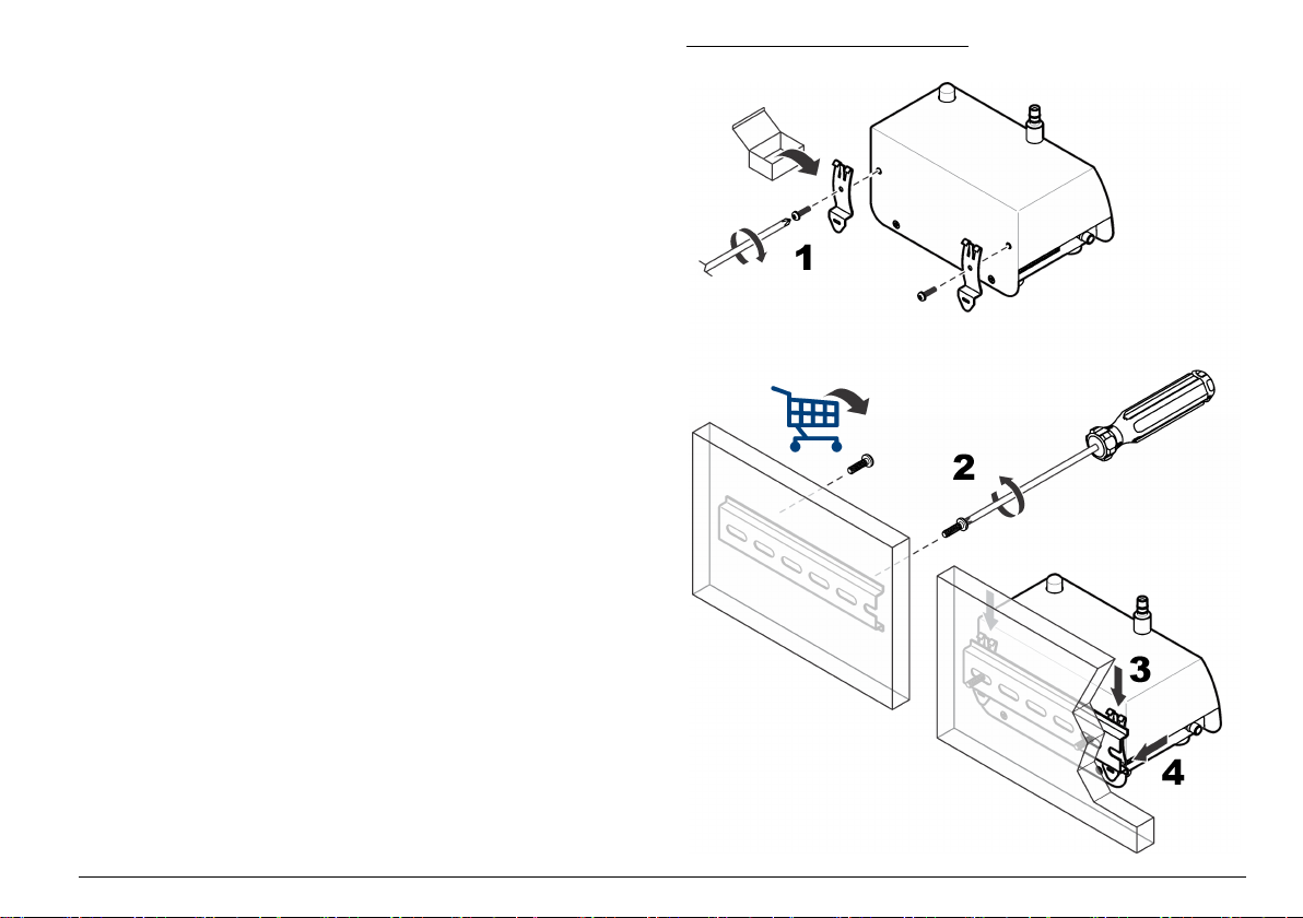
Instrucciones del sistema de vacío
•
Coloque la bomba de vacío en una ubicación central. Debe haber
vacío suficiente para todos los instrumentos de la red.
• Utilice un colector de distribución para mantener la pérdida de vacío
en unos niveles mínimos. Entre los materiales que se suelen utilizar
para la distribución de vacío se incluyen tuberías de cobre soldadas,
tuberías de PVC cuyo espesor de pared sea igual a 80 o tuberías
como Cobolite®.
• Utilice longitudes de tubo cortas para suministrar el vacío desde el
colector de distribución hasta el instrumento individual. Utilice una
válvula de distribución y una conexión de la dimensión correcta en
cada ubicación del instrumento.
• Intente utilizar el mínimo número de uniones, codos y las menores
longitudes de tubo desde la fuente de vacío hasta los instrumentos
para mantener la pérdida de vacío de un sistema en los niveles
mínimos.
Instalación mecánica
Montaje del instrumento
Instale el instrumento en una superficie nivelada o en una pared con uno
de los siguientes kits de montaje:
• Kit de barra DIN (suministrado con el instrumento): utilícelo para
retirar rápidamente el instrumento de la pared.
• Soporte de montaje en pared (opcional): utilícelo para una instalación
permanente. Consulte las instrucciones que se suministran con el kit.
Consulte los pasos ilustrados en la Figura 5 para ver la instalación con
barra DIN. Para retirar el instrumento de la barra, eleve la parte inferior
del instrumento.
Figura 5 Instalación en barra DIN
Español 55
Page 56

Instalación de la sonda de muestreo
Consulte Instrucciones de la sonda de muestreo en la página
de la instalación para evitar la contaminación del instrumento y obtener
una muestra representativa del área. La posición de la sonda de
muestreo (isocinética) es importante para la precisión del recuento.
Opciones de la sonda de muestreo
Los kits opcionales están disponibles para la instalación de la sonda de
muestreo. Consulte Figura 6.
• Montaje directo: No es necesario ningún kit. La sonda de muestreo
se instala en una pequeña pieza de tubo directamente en la parte
superior de la conexión de entrada de aire de muestreo en el
instrumento. Utilice la instalación de montaje directo cuando el
instrumento pueda colocarse en la misma ubicación donde se recoge
la muestra. Utilice la instalación de montaje directo para mantener la
pérdida de partículas a unos niveles mínimos.
• Montaje en pared, 90 grados: La sonda se conecta con un tubo de
acero inoxidable (90 grados) y un soporte de pared.
• Soporte de pared de tipo T: La sonda de muestreo se instala en un
soporte de pared. Los tubos se cortan para conectar la sonda con el
contador.
• Montaje en pared vertical: La sonda de muestreo se conecta con un
soporte y un tubo de acero inoxidable. Utilice la instalación de
montaje en pared vertical del equipo con tubos de acero inoxidable.
56 antes
Figura 6 Opciones de instalación de la sonda de muestreo
1 Montaje directo 3 Montaje en pared vertical
2 Montaje en pared, 90 grados 4 Soporte en pared de tipo T
Instrucciones de la sonda de muestreo
A V I S O
No utilice este instrumento para controlar el aire que contiene vapores de
adhesivos de secado u otras sustancias químicas. Estos vapores pueden cubrir
de forma permanente los elementos ópticos del sensor u otras piezas internas.
No utilice este instrumento para controlar el aire que contiene vapores con
sustancias corrosivas. Estos vapores pueden causar de forma rápida daños
permanentes en los elementos ópticos o electrónicos del contador.
A V I S O
56 Español
• Flujo laminar: Instale al menos una sonda de muestreo para cada
2,3 m2 (25 pies2) de área de superficie.
Page 57

• Flujo turbulento: Instale al menos dos sondas de muestreo en cada
sala limpia.
•
Asegúrese de que la sonda de muestreo (isocinética) está orientada
hacia la dirección del flujo. Consulte la Figura 2 en la página 52.
• Mantenga la sonda de muestreo a una distancia mínima de 30 cm
(12 pulg.) de materiales sueltos, polvo, líquidos y pulverizadores.
• Mantenga la sonda de muestreo a una distancia mínima de 30 cm
(12 pulg.) de posibles fuentes de contaminación, tales como un
ventilador de escape del instrumento.
• No utilice este instrumento para controlar el aire que contiene las
sustancias que figuran en la Tabla 4.
Tabla 4 Contaminantes
Sustancia Daño
Polvo Contamina el sensor y produce resultados incorrectos o fallos en el
Líquido Contamina los elementos ópticos internos del sensor y modifica la
Humo Contamina el sensor.
instrumento.
calibración del instrumento.
Nota: El líquido puede encontrarse en el aire en forma de gotas.
Instalación de los tubos
Utilice las bridas o los ganchos de los tubos para sujetar los tubos y
evitar la formación de acodaduras. Una acodadura en los tubos
reduciría el flujo de aire y produciría los siguiente problemas
• Una disminución en el caudal de entrada de aire que puede causar la
acumulación de partículas en las paredes internas de los tubos. Estas
partículas no se contarán. Las partículas acumuladas pueden
liberarse de manera aleatoria, lo que redundará en picos en los
recuentos.
Recopilación de elementos:
• Tubo de entrada de aire: Hytrel® Bevaline, Tygon® o equivalente.
• Tubo de vacío: Hytrel Bevaline, Tygon o equivalente.
• Bridas o ganchos de tubos
s:
1. Corte el tubo de entrada de aire de forma que tenga la longitud
suficiente para conectar el
instrumento con la sonda de muestreo.
Procure que la longitud del tubo sea la mínima posible. Asegúrese
de que la longitud no sea superior a 3 m (10 pies).
2. Corte el tubo de vacío de forma que pueda conectar el contador con
la fuente de vacío. Procure que la longitud del tubo sea la mínima
posible.
3. Cubra los extremos de los tubos para asegurarse de que no entra
material no deseado en los tubos durante su instalación.
4. Conecte los tubos con ganchos o bridas a intervalos que no superen
una distancia de 1,2 m (4 pies). Asegúrese de que los tubos tiene un
radio de acodadura mínimo de 10 cm (4 pulg.) de forma que no se
reduzca el flujo de aire.
5. Conecte los tubos de entrada de aire con las conexiones de entrada
de aire del instrumento. Conecte el otro extremo del tubo a la sonda
de muestreo suministrada.
6. Conecte el tubo de vacío a la conexión en la parte inferior (o lateral)
del contador. No conecte el otro extremo al vacío hasta que la sala
esté lista para el muestreo.
Instalación eléctrica
Información de seguridad respecto al cableado
A D V E R T E N C I A
Peligro de electrocución. Asegúrese de que sea fácil acceder a la
desconexión de alimentación local.
Siempre desconecte la energía del instrumento antes de realizar conexiones
eléctricas.
Obedezca todas las instrucciones de seguridad cuando se realicen
conexiones eléctricas al instrumento.
A V I S O
Español 57
Page 58

Conexión a la alimentación
Conecte una fuente de alimentación externa (24 VCC) al conector de
5 o 10 patillas. Consulte la Figura 7 y la Tabla 5 o la Figura 8 y la
Tabla 6 para obtener información sobre el cableado. Asegúrese de que
la tensión de salida de la fuente de alimentación externa no exceda los
28 VCC.
El número máximo de
fuente de alimentación externa puede variar en función de la opción de
comunicación. Póngase en contacto con el servicio de asistencia técnica
para obtener más información.
Consulte los pasos ilustrados de la Figura 9 para obtener información
sobre el cableado del conector de 5 patillas. Consulte los pasos
ilustrados de la Figura 10 para obtener información sobre el cableado
del conector de 10 patillas.
Figura 7 Conector de 5 patillas
Tabla 5 Cableado del conector de 5 patillas
Patilla Descripción Patilla Descripción
1 — 4 Unidad de alimentación
2 — 5 Común
3 Común (puesta a tierra con
instrumentos que pueden conectarse a una
eléctrica principal (9-28 VCC,
1 A máximo)
blindaje)
Figura 8 Conector de 10 patillas
Tabla 6 Cableado del conector de 10 patillas
Patilla Unidad
RS485
1 RS485 A — Canal 1+ Fuente de
2 RS485 B — Canal 1- Salida de bucle de
3 RS485 A RS232 TX Canal 2+ Salida de bucle de
4 RS485 B RS232 RX Canal 2- Salida de bucle de
5 — — — Salida de bucle de
6 — — Estado + —
7 — — Estado - —
8 Común (puesta a tierra con blindaje)
9 Unidad de alimentación eléctrica principal (9-28 VCC, 1 A máximo)
10 Común
Unidad
RS232
Unidad de
impulsos
Unidad analógica
alimentación en
bucle externo de
24 VCC
Canal 1
Canal 2
Canal 3
Canal 4
58 Español
Page 59

Figura 9 Cableado del conector de 5 patillas Figura 10 Cableado del conector de 10 patillas
Español 59
Page 60

Instalación de comunicaciones en serie
Consulte la Figura 8 en la página
conectar un instrumento con la comunicación en serie (RS485, RS232 o
impulsos).
Cableado de la red
Pueden incluirse hasta 32 instrumentos (con una carga de 12 K cada
uno) en una red RS485 (EIA-485) con protocolo de comunicación
RS485 Modbus o FXB. Utilice un cable de alta calidad para las
comunicaciones en serie como Belden 9841. El fabricante recomienda
que la longitud de la red no sea superior a 1.200 m (3.937 pies).
En la Figura 11 se muestra un diagrama de cableado de red típico.
Figura 11 Cableado de la red
1 Contador de partículas 5 Cable
2 Contador de partículas 6 Transformador de RS232 a RS485
3 A contadores de partículas
adicionales
4 PC
58 y la Tabla 6 en la página 58 para
7 Cable de red
Conexión a Ethernet
Conecte
100Base-T estándar de Ethernet. Asegúrese de que el cableado es
compatible para la velocidad de la red para evitar problemas de
intermitencia. Para este instrumento, la red 10Base-T estándar de
Ethernet es suficiente para transmitir datos y ofrece una mayor
tolerancia en relación con errores de instalación.
• Longitud: longitud de un solo cable 100 m (328 pies) como máximo
• Repetidores: 4 (máximo)
• Tipo de conector: RJ45 (convención T-568B de cableado de Ethernet
instrumentos con comunicación Ethernet a una red 10Base-T o
(pueden utilizarse repetidores para aumentar la distancia)
estándar)
Conexión de las salidas analógicas
Conecte los instrumentos con la función de salida analógica a un
sistema de adquisición de datos. Consulte la Figura 8 en la página 58 y
la Tabla 6 en la página 58 para obtener información sobre el cableado.
Cuando se utiliza un suministro de corriente eléctrica de +24 VCC, el
suministro de corriente eléctrica también se puede utilizar como una
fuente de alimentación en bucle de 4 a 20 mA si hay una intensidad de
señal de salida suficiente para el bucle. Consulte la Figura 12. La
Figura 13 muestra el límite máximo de la resistencia total del bucle
(combinación de carga y de cableado) permitido.
Los instrumentos con la función de salida analógica envían una señal de
4 a 20 mA que es proporcional al número de recuentos en un tiempo de
muestreo determinado. Las salidas analógicas se actualizan al final de
cada período de muestra. Un sistema de adquisición de datos recibe la
señal. Los instrumentos con la función de salida analógica pueden tener
dos o cuatro tamaños de canal. Las unidades analógicas no se pueden
utilizar en una configuración de red.
Utilice el software de herramientas de configuración para definir el
número máximo de recuentos que correspondan a la señal 20 mA.
Consulte Configuración del instrumento en la página 63.
60 Español
Page 61

Cuando se suministra corriente eléctrica, las salidas analógicas de los
canales son de 4 mA. Cuando se interrumpe el suministro eléctrico o se
produce un error del sensor o del flujo, la salida analógica de los
canales es inferior a 2 mA. Si el usuario deshabilita un canal, la salida
del canal es inferior a 2 mA. Cualquier señal inferior a 4 mA (valor de
cuenta cero) genera un número negativo en el sistema de adquisición
de datos que detecta un problema con la señal del
instrumento.
Configure el software de control central para que se active una alarma
cuando se detecte una señal inferior a 4 mA (valor de cuenta cero) y a
fin de obtener una alarma de pérdida de alimentación eléctrica, flujo o
sensor, según sea necesario.
Figura 12 Configuración de alimentación en bucle
1 Configuración de alimentación en
bucle común
2 Configuración de alimentación en
bucle separada
3 Suministro de alimentación en
bucle de 24 VCA
4 Suministro en bucle + 8 Suministro de alimentación +
5 Común
6 Sistema de recopilación de 4 a
20 mA
7 Suministro de alimentación pde
24 VCC
Español 61
Page 62

Figura 13 Límite máximo para el funcionamiento del lazo de
corriente
1 Tensión de suministro en bucle 3 Fuera del rango operativo (por
2 Rango operativo aceptable (por
encima de la línea)
debajo de la línea)
4 Límite máximo de resistencia en
bucle total
Puesta en marcha
Limpieza de las superficies externas
A V I S O
No pulverice nunca el instrumento directamente con un chorro de vapor de
peróxido de hidrógeno (VHP) o líquido. Si las soluciones líquidas entran en el
conducto del contador o los componentes electrónicos, se producen daños en el
sensor.
No permita que el vapor de sustancias químicas desinfectantes entre en la
carcasa del
electrónicos del instrumento.
instrumento ni que entre en contacto con los componentes
A V I S O
Limpie las superficies exteriores con una toallita sin pelusas humedecida
con alcohol isopropílico (AIP). La sonda de muestreo (isocinética) se
puede limpiar mediante autoclave.
Limpieza de las superficies internas
Utilice
un filtro de cuenta cero para eliminar contaminantes tales como
partículas, pelusas o polvo de las superficies internas del instrumento y
de los tubos de entrada de aire. Cuando el recuento llega a cero, las
superficies internas y los tubos de aire están limpios.
Recopilación de elementos: filtro de cuenta cero
1. Conecte el filtro de cuenta cero al tubo de entrada de aire.
El filtro de cuenta cero evita la entrada de cualquier partícula externa
en el instrumento.
2. Inicie la recogida de muestras y ponga en funcionamiento el
instrumento durante al menos 30 minutos. Consulte Funcionamiento
manual en la página 70.
3. Supervise el aire de la sala a intervalos de 5 minutos y continúe
hasta que el contador de partículas indique 0–1.
Opcional: Para registrar los datos, establezca el ajuste Sample
Timing: Sample (Tiempo de muestra: Muestra) en 5 minutos.
Consulte Configuración del instrumento en la página 63.
4. Si el contador de partículas no llega a 0–1 transcurridos nueve o
diez periodos de muestreo de 5 minutos, purgue el instrumento
durante la noche. Consulte Purga del instrumento en la página 62.
Purga del instrumento
Realice una purga para obtener un recuento de partículas de 0-1.
Normalmente, se realiza una purga antes de una prueba para
asegurarse de que el instrumento cuenta con un valor de referencia.
1. Retire aproximadamente 2,5 cm (1 pulg.) de tubo del extremo de la
sonda de muestreo del tubo de entrada de aire para eliminar
cualquier sección estirada o desviada.
2. Conecte un filtro de cuenta cero al tubo de entrada de aire.
62 Español
Page 63

3. Ponga en funcionamiento el
4. Si, transcurridas 24 horas, no se muestra un recuento de partículas
de 0 a 1, identifique si la fuente de las partículas es el tubo de
entrada de aire.
a. Instale un filtro de cuenta cero directamente en la conexión de
entrada de aire.
b. Ponga en funcionamiento el instrumento otros 15 minutos.
c. Controle el aire de la sala durante 5 minutos y registre los
resultados. Realice este paso hasta cuatro veces hasta que el
recuento de partículas sea de 0 a 1 en una muestra de
5 minutos.
d. Si se muestra un recuento de partículas de 0 a 1, los tubos de
entrada de aire serán la fuente de las partículas. Sustituya los
tubos de entrada de aire.
e. Si el recuento de partículas no alcanza 0-1, póngase en contacto
con el servicio de asistencia técnica.
instrumento durante 24 horas.
• Adaptador de USB a RS232 si el PC no dispone de un puerto RS232
1. Asegúrese de que Microsoft .Net Framework esté instalado en el
PC. En caso contrario, abra el archivo dotnetfx.exe en el CD de
herramientas de configuración e instale la aplicación.
Nota: El usuario debe haber iniciado sesión en el PC como administrador.
2. Copie y pegue el archivo SetupUtility.exe del CD de herramientas de
configuración en el PC.
3. Conecte el cable del puerto de servicio al puerto de servicio en el
instrumento y un puerto de comunicación al PC.
Configuración del instrumento
Utilice el software de herramientas de configuración para configurar los
parámetros almacenados en cada instrumento. Cuando se suministra
corriente eléctrica al instrumento, busca una nueva configuración. Si no
se detecta ninguna nueva configuración, se utilizará la configuración
guardada anteriormente.
Operación
Configuración
Para llevar a cabo la configuración inicial, conecte el instrumento a un
PC.
Tras la configuración inicial, cambie los ajustes de configuración según
sea necesario mediante la conexión directa a un PC o mediante la
conexión con ModbusTCP. Al realizar la configuración a través de una
red, solo se pueden cambiar los ajustes de la red LAN. Consulte
Configuración de los ajustes de LAN a través de una red
en la página 66.
Conexión con un PC
Recopilación de elementos:
• CD de herramientas de configuración
• Cable del puerto de servicio
• PC con Windows® 2000 Professional, Windows XP Professional,
Windows Vista (de 32 bits), Windows 7 (de 32 bits o de 64 bits en
modo de emulación XP)
1. Abra el archivo SetupUtility.exe que está instalado en el PC para
iniciar el programa de herramientas de configuración.
2. Seleccione la pestaña Basic Setup (Configuración básica).
3. Localice el campo Port (Puerto) en el lado derecho de la ventana.
Seleccione el puerto COM en el PC al que esté conectado el
instrumento.
4. Haga clic en Read Instrument (Leer instrumento). Las herramientas
leen los datos almacenados en el instrumento.
5. Asegúrese de que los datos en la sección de información del
instrumento son correctos (número de modelo, opción de
comunicación, versión de firmware y dirección de comunicación,
según sea necesario).
Español 63
Page 64

6. En el sección General, seleccione los ajustes.
Opción Descripción
Count Mode (Modo de
recuento)
Sample Timing: Sample
(Tiempo de muestreo:
Muestra)
Sample Timing: Hold
(Tiempo de muestreo:
Retención)
Count Cycles (Ciclos de
recuento)
Slave Address/Location
ID (ID de
ubicación/dirección
esclava)
Comm Timeout (Tiempo
de espera de
comunicación)
Location Name (Nombre
de la ubicación)
Establece el modo de recuento. No afecta a la
salida analógica de las unidades analógicas.
Differential (Diferencial): Los recuentos de
partículas que se muestran para cada canal
son los recuentos de cada tamaño de canal.
Cumulative (Acumulativo) (valor
predeterminado): Los recuentos de partículas
que se muestran para cada canal son los
recuentos de cada tamaño de canal junto con
los tamaños de canal mayores. Por ejemplo, si
el canal es de 0,3 µm, las partículas que sean
de 0,3 µm y las de mayor tamaño se incluirán
en el recuento.
Establece el periodo de tiempo para cada
muestra (valor predeterminado = 00:01:00 =
1 minuto).
Establece el periodo de tiempo que se detiene
la recopilación de datos tras la obtención de las
muestras (valor predeterminado = 00:00:00).
Establece el número de muestras obtenido
antes de detener la recopilación de datos y de
que comience el periodo de tiempo de
retención (0 = muestreo continuo).
No cambiar (valor predeterminado: P1).
Establece el número de segundos que debe
transcurrir tras un fallo en la comunicación
antes de emitir una alarma de comunicación.
Para deshabilitar las alarmas de configuración,
establezca el ajuste en 0. En el caso de
instrumentos con una función de salida
analógica, establezca el ajuste en 0.
Establece un identificador unívoco para el
instrumento.
Opción Descripción
System Date/Time
(Fecha/hora del sistema)
Moving Cumulative
Counts (Recuentos
acumulativos
cambiables)
Store Partial Records
(Almacenar registros
parciales)
Temp Units °C (Unidad
de temperatura: °C)
Remote LCD (LCD
remota)
Count Alarms (Alarmas
de recuentos)
Establece la fecha (AAAA/MM/DD) y la hora
(HH:MM:SS, formato de 24 horas).
Establece el número de recuentos de muestras
del Canal 1 o del Canal 2 que se fusionan y se
muestran en el Canal 3 y el Canal 4. En el
Canal 3 figuran los recuentos acumulativos del
Canal 1. En el Canal 4 figuran los recuentos
acumulativos del Canal 2.
Permite almacenar los datos de muestras
parciales en el búfer. Una recopilación de datos
de muestras parcial se produce cuando se
detiene una muestra antes de finalizarla.
Cambia las unidades de temperatura de
Fahrenheit (valor predeterminado) a Celsius.
No disponible (deshabilitado).
Establece el número mínimo de partículas de
cada canal que activará una alarma de
recuento.
Para ver los tamaños de los canales,
seleccione la pestaña Data Display
(Visualización de datos). Consulte la Figura 15
en la página 71.
64 Español
Page 65

Opción Descripción
Sample Mode (Modo de
muestreo)
Flow Units (Unidades de
caudal)
7. Si se conecta una pila de luces externa opcional al
Establece el modo de muestreo.
Auto (Automático): La recopilación de datos de
la muestra comienza de forma automática al
suministrar corriente eléctrica al instrumento.
Manual: La recopilación de datos de la muestra
no comienza de forma automática al
suministrar corriente eléctrica al instrumento.
La recopilación de datos de la muestra debe
iniciarse de manera manual. Consulte
Funcionamiento manual en la página 70.
Nota: Las unidades Ethernet con salida
analógica no se pueden establecer en la
opción Manual, ya que no hay una
comunicación bidireccional con el software de
control central. Estas unidades siempre
comenzarán en el modo Auto (Automático).
Establece las unidades de caudal de aire.
Opciones: CFM (PCM, pies cúbicos por
minuto) o LPM (L/M, litros por minuto).
instrumento,
utilice la sección de diagnóstico para establecer si el indicador
luminoso de estado debe parpadear o no en un color con el objeto
de identificar que el cableado es correcto.
Nota: No es posible guardar los ajustes de diagnóstico y no afectarán al
funcionamiento del instrumento.
8. En el caso de unidades con salida analógica, cambie la
configuración de la salida analógica entre 4 y 20 mA en la sección
de salida analógica.
Opción Descripción
Full Scale
(Escala
completa)
Output State
(Estado de
salida)
Establece el recuento de partículas de cada canal que se
corresponde con una señal de salida de 20 mA (valor
predeterminado = 1000). Un recuento de partículas cero se
corresponde con una señal de salida de 4 mA.
Nota: No se informa de las alarmas de recuentos al
software de control central. Configure el software de
control central para que se activen las alarmas de
recuentos según sea necesario.
Establece el estado de salida. Establézcalo en Normal
para un funcionamiento normal.
Zero (Cero): Mantiene la señal de salida en 4 mA.
Span (Intervalo): Mantiene la señal de salida en PP20 mA.
9. Para una comunicación en serie (solo unidades RS485), cambie el
ajuste de comunicación en la sección Serial (Serie). Opciones: FXB,
Modbus, R48XX Compatibility (Compatibilidad con R48X) y FXB1. Si
selecciona Modbus, introduzca la dirección esclava. Cuando la
dirección sea 31 o inferior, utilice los interruptores DIP en la parte
inferior del instrumento para establecer la dirección. Consulte Salida
en serie de RS485 con protocolo Modbus RTU
Nota: Si se introduce una dirección de 32 o superior, se ignoran los ajustes de
los interruptores DIP y se utiliza el valor introducido.
en la página 68.
10. Para una comunicación por impulsos (solo unidades RS485),
seleccione el tamaño de canal de la salida de impulso del Canal 2 en
la sección Pulse (Impulso) (valor predeterminado = Count Channel
2 [Recuento de Canal 2]). La salida de impulso del Canal 1 siempre
se corresponde con el tamaño de partícula del Canal 1.
11. Para comunicaciones mediante Ethernet (solo unidades Ethernet),
consulte Configuración de los ajustes de Ethernet en la página 66.
12. Haga clic en Save Settings (Guardar ajustes) para guardar los
cambios.
Español 65
Page 66

Configuración de los ajustes de Ethernet
1. Para las unidades Ethernet
sin capacidad de salida analógica,
cambie los ajustes de Ethernet en la sección de Ethernet. Los
ajustes de Ethernet solo debe cambiarlos un profesional de redes.
Opción Descripción
MAC Control de acceso a medios: Muestra la dirección del
DHCP/APIPA Habilita o deshabilita el direccionamiento IP estático o
IP Address
(Dirección IP)
Subnet Mask
(Máscara de
subred)
Server Port (Puerto
de servidor)
Client Port (Puerto
de cliente)
Gateway (Puerta
de enlace)
hardware permanente única (solo lectura)
dinámico mediante la conexión con un servidor DHCP
(valor predeterminado = deshabilitado). Cuando está
habilitado, el instrumento obtiene una dirección IP y
una máscara de subred de manera automática tras el
encendido.
Si no hay disponible ningún servidor DHCP, el
instrumento utiliza el APIPA para obtener una
dirección IP y una máscara de subred.
• Rango de direcciones IP del APIPA: entre
169.254.0.0 y 169.254.255.255
• Máscara de subred: 255.255.0.0 (red de Clase B)
Para direcciones IP estáticas, cada instrumento
basado en una red LAN debe contar con una
dirección IP única. Rango: entre 169.254.0.0 y
169.254.255.255 (valor predeterminado: 169.254.1.2).
Los instrumentos del mismo tipo que se comunican
con un paquete de software único (esto es, FMS),
utilizan la misma máscara de subred (valor
predeterminado: 255.255.0.0). Rango: entre 0 y 255,
solo números enteros.
Puerto de escucha del servidor ModbusTCP (valor
predeterminado: 502). Rango: entre 0 y 65535, solo
números enteros.
No disponible (deshabilitado)
Router o punto de acceso a otra red (valor
predeterminado: 169.254.1.5)
Opción Descripción
Remote Server IP
(IP del servidor
remoto)
Ethernet Protocol
(Protocolo
Ethernet)
No disponible (deshabilitado)
Establece el protocolo Ethernet en Modbus o FXB.
2. Para unidades Ethernet con capacidad de salida analógica, consulte
Configuración de los ajustes de LAN a través de una red
en la página
66 para configurar los ajustes de Ethernet.
3. Haga clic en Save Settings (Guardar ajustes) para guardar los
cambios.
Configuración de los ajustes de LAN a través de una red
1. En el software de herramientas de configuración, seleccione la
pestaña LAN Setup (Configuración de LAN). El software busca
instrumentos conectados a una red LAN. Se muestran los
instrumentos conectados a una red LAN que se hayan encontrado.
2. Seleccione un instrumento para visualizar los ajustes de
configuración del instrumento conectado a una red LAN.
3. Cambie los ajustes de LAN. Consulte la tabla de opciones en
Configuración de los ajustes de Ethernet en la página 66.
4. Haga clic en Save Settings (Guardar ajustes) para guardar los
cambios.
Realización de una prueba de salida analógica
En el caso de instrumento con función de salida analógica, realice una
prueba de salida analógica.
1. Conecte las salidas analógicas a las resistencias de carga del
sistema de adquisición de datos.
Nota: De manera alternativa, instale un conjunto de resistencias de carga con
una precisión del 0,1 % y una capacidad de al menos 0,25 W a lo largo de la
66 Español
Page 67

salida analógica. Se suelen utilizar los siguientes valores de resistencia de
carga: 100, 250 o 500 ohmios.
2. Deje que una pequeña cantidad de partículas fluya por el
instrumento para obtener un recuento del canal de prueba.
Nota: Un método para obtener recuentos es utilizar un filtro de cuenta cero y
colocar un orificio para el pasador en el tubo que se encuentra entre el filtro y
el instrumento.
3. En la pestaña Basic Setup (Configuración básica) del software de
herramientas de configuración, establezca los siguientes ajustes de
forma temporal:
• Ciclos de recuento = 1
• Tiempo de muestreo: Retención (10 segundos o más)
4. Haga clic en Save Settings (Guardar ajustes).
5. Seleccione la pestaña Data Display (Visualización de datos), a
continuación haga clic en Monitor si aparece, de forma que los
datos que se muestran se puedan actualizar de forma continua a
medida que se adquiere cada muestra.
6. Haga clic en Sample (Muestra) si aparece esta opción para iniciar la
recogida de muestras.
7. Cuando el valor Status (Estado) cambie de "Count" (Recuento) a
"Stop" (Detener), mida la tensión en las resistencias de carga de
cada canal. Anote también los recuentos de cada canal que se
muestran en pantalla.
8. Utilice la siguiente ecuación para calcular la tensión esperada de los
recuentos que se muestran. Asegúrese de que las tensiones
medidas y las calculadas coinciden.
Tensión = (((SC ÷ FC × 16) + 4) ÷ 1000) × RL
Donde:
SC = recuento de muestra al final del periodo de muestreo.
FC = recuento de canal a escala completa. Consulte los ajustes
analógicos en el software de herramientas de configuración.
RL = valor de la resistencia de carga en ohmios.
La tensión de salida esperada cuando el recuento de canal a escala
completa es de 1.000 con una resistencia de 100, 250 y 500 ohmio
se muestra en la Tabla 7.
9. Para volver a realizar la prueba, lleve a cabo los pasos 7 y 8.
10. En el caso de unidades con un monitor de flujo, retire de forma
temporal el sistema de vacío central del
instrumento.
11. Mientras la alarma de flujo está activada, mida la tensión en las
resistencias de carga de cada canal.
12. Utilice la siguiente ecuación para calcular la tensión esperada.
Asegúrese de que las tensiones medidas s y las calculadas
coinciden.
Tensión = < (0,002 × RL)
Donde: RL = valor de la resistencia de carga en ohmios.
Ejemplo: Para una resistencia de 100 ohmios, la tensión debe ser
inferior a 0,20 V.
13. En la pestaña Basic Setup (Configuración básica), restablezca los
valores de configuración anteriores.
14. Haga clic en Save Settings (Guardar ajustes).
Tabla 7 Tensión de salida con resistencias de 100, 250 y
500 ohmios
Recuento de muestras 100 Ω 250 Ω 500 Ω
0 0,40 V 1,00 V 2,00 V
100 0,56 V 1,40 V 2,80 V
200 0,72 V 1,80 V 3,60 V
300 0,88 V 2,20 V 4,40 V
400 1,04 V 2,60 V 5,20 V
500 1,20 V 3,00 V 6,00 V
600 1,36 V 3,40 V 6,80 V
700 1,52 V 3,80 V 7,60 V
800 1,68 V 4,20 V 8,40 V
900 1,84 V 4,60 V 9,20 V
1.000 2,00 V 5,00 V 10,00 V
Español 67
Page 68

Salida en serie de RS485 con protocolo Modbus RTU
Los instrumentos con la opción de comunicación RS485 FXB utilizan el
protocolo Modbus RTU estándar del sector. En este modo de
comunicación, una serie de registros contienen datos sobre los
resultados de medición y los parámetros de funcionamiento.
Cuando se establece una conexión ModbusTCP, el usuario puede
utilizar todas las opciones de configuración en el mapa de registro
Modbus. Consulte el sitio Web de la empresa para obtener información
sobre el mapa de registro Modbus. Anote los controladores que se van a
comunicar con el
Modbus RTU.
El circuito de la red en serie de RS485 suministra las comunicaciones
para un máximo de 32 instrumentos y un ordenador de control. Solo un
instrumento puede transmitir datos cada vez. Cada instrumento debe
tener una dirección de instrumento única.
1. De la vuelta al instrumento. El interruptor DIP se encuentra en la
parte inferior del instrumento.
2. Cambie el ajuste del interruptor DIP para seleccionar una dirección
de red única para el instrumento. Consulte la Tabla 8.
Nota: La dirección 0 solo se puede utilizar con el protocolo FXB. La dirección
0 se conserva para utilizarlo como una dirección de transmisión para Modbus
RTU. Si la dirección 0 se establece con el protocolo Modbus, el instrumento
utilizará la dirección 1.
Tabla 8 Configuración de interruptor DIP para dirección de red
Dirección
de red
0 Apagado Apagado Apagado Apagado Apagado
1 Encendido Apagado Apagado Apagado Apagado
2 Apagado Encendido Apagado Apagado Apagado
3 Encendido Encendido Apagado Apagado Apagado
4 Apagado Apagado Encendido Apagado Apagado
5 Encendido Apagado Encendido Apagado Apagado
instrumento mediante estos registros con el protocolo
Interruptor1 Interruptor2 Interruptor3 Interruptor4 Interruptor
5
Tabla 8 Configuración de interruptor DIP para dirección de red
(continúa)
Dirección
de red
6 Apagado Encendido Encendido Apagado Apagado
7 Encendido Encendido Encendido Apagado Apagado
8 Apagado Apagado Apagado Encendido Apagado
9 Encendido Apagado Apagado Encendido Apagado
10 Apagado Encendido Apagado Encendido Apagado
11 Encendido Encendido Apagado Encendido Apagado
12 Apagado Apagado Encendido Encendido Apagado
13 Encendido Apagado Encendido Encendido Apagado
14 Apagado Encendido Encendido Encendido Apagado
15 Encendido Encendido Encendido Encendido Apagado
16 Apagado Apagado Apagado Apagado Encendido
17 Encendido Apagado Apagado Apagado Encendido
18 Apagado Encendido Apagado Apagado Encendido
19 Encendido Encendido Apagado Apagado Encendido
20 Apagado Apagado Encendido Apagado Encendido
21 Encendido Apagado Encendido Apagado Encendido
22 Apagado Encendido Encendido Apagado Encendido
23 Encendido Encendido Encendido Apagado Encendido
24 Apagado Apagado Apagado Encendido Encendido
25 Encendido Apagado Apagado Encendido Encendido
26 Apagado Encendido Apagado Encendido Encendido
27 Encendido Encendido Apagado Encendido Encendido
Interruptor1 Interruptor2 Interruptor3 Interruptor4 Interruptor
5
68 Español
Page 69

Tabla 8 Configuración de interruptor DIP para dirección de red
(continúa)
Dirección
de red
28 Apagado Apagado Encendido Encendido Encendido
29 Encendido Apagado Encendido Encendido Encendido
30 Apagado Encendido Encendido Encendido Encendido
31 Encendido Encendido Encendido Encendido Encendido
Interruptor1 Interruptor2 Interruptor3 Interruptor4 Interruptor
5
Salida en serie de RS485 con protocolo FXB
Los instrumentos con la opción de comunicación RS485 FXB utilizan el
protocolo FXB estándar del sector. Consulte el sitio Web de la empresa
para obtener información sobre el protocolo.
Comunicación por impulsos
Los instrumentos con opción de comunicación por impulsos envían una
señal de impulso de 8 µs cuando se detecta una partícula. Consulte la
Figura 14. Un contador de impulsos externo o un sistema de adquisición
de datos recibe la señal de impulso y cuenta los impulsos como
partículas.
Los instrumentos con comunicación por impulsos tienen dos canales de
salida de impulsos (Canal 1 y Canal 2). El Canal 1 envía una señal de
impulso cuando se detecta el tamaño de partícula del Canal 1. El Canal
2 envía una señal de impulso cuando se detecta el tamaño de canal que
ha seleccionado el usuario.
La comunicación por impulsos incluye una señal de salida de estado de
baja a alta cuando hay activada una alarma. La comunicación por
impulsos no puede utilizarse en una configuración de red.
Establezca la dirección de red para los
por impulsos en 1. Consulte la Tabla 8 en la página 68.
instrumentos con comunicación
La señal de impulso se puede enviar en uno de los dos modos de
recuento:
• Modo diferencial (predeterminado): Se envía una señal al Canal
1 cuando una partícula se encuentra entre los umbrales de tamaño
del primer y el segundo canal. Se envía una señal al Canal 2 cuando
una partícula es mayor que el umbral de tamaño del canal
seleccionado por el usuario.
• Modo acumulativo: Se envía una señal al Canal 1 cuando una
partícula es mayor que el umbral de tamaño del primer o del segundo
canal. Se envía una señal al Canal 2 cuando una partícula es mayor
que el umbral de tamaño del canal seleccionado por el usuario.
Figura 14 Ejemplo de modo de recuento diferencial frente a
acumulativo
1 Señal de impulso enviada desde el
contador
2 Transferencia de datos en modo
diferencial frente a modo
acumulativo
3 Canal 2 6 Recuento acumulativo: tres de
4 Canal 1
5 Recuento diferencial: uno de
partículas de 0,3 µm y dos de
partículas de 5,0 µm
partículas de 0,3 µm y dos de
partículas de 5,0 µm
Español 69
Page 70

Funcionamiento manual
Utilice el software de herramientas de configuración con una conexión a
PC directa o a través de una conexión LAN para operar manualmente el
instrumento
1. Abra el archivo SetupUtility.exe para iniciar el software de
2. Seleccione la pestaña Data Display (Visualización de datos).
3. Utilice los botones para operar el instrumento.
.
herramientas de configuración.
Consulte la Figura 15 para ver los datos que se muestran.
Nota: Los botones cambian en función del estado del sistema.
Opción Descripción
Monitor (Monitor) Muestra los datos actualizados continuamente
Stop Monitor (Detener
monitor)
Sample (Muestra) Inicia la recogida de muestras. Las muestras se
Stop Count (Detener
recuento)
Active Mode (Modo
activo)
Inactive Mode (Modo
inactivo)
Display Buffered Data
(Mostrar datos
almacenados)
en tiempo real.
Detiene los cambios en los datos que se
muestran en la pantalla.
adquieren según los ajustes de la pestaña Basic
Setup (Configuración básica). El instrumento
pasa al modo activo si se encuentra en modo
inactivo.
Detiene la recogida de muestras.
Activa el láser interno . Habilita las alarmas.
Desactiva el láser interno y la . Deshabilita las
alarmas.
Muestra los datos de la última muestra
finalizada. Se actualiza a medida que finaliza
cada muestra.
Opción Descripción
Download Buffer
(Descargar búfer)
Erase Buffer (Borrar
búfer)
Guarda una copia de los registros de datos del
búfer en el PC en formato de archivo de texto
(CSV).
Borra todos los registros del búfer.
70 Español
Page 71

Figura 15 Pantalla de datos en tiempo real
Calibración
El instrumento
el fabricante para la calibración del instrumento.
no lo puede calibrar el usuario. Póngase en contacto con
Mantenimiento
1 Alarmas activas (Sensor, flujo,
comunicación, recuento1)
2 Tamaño de canal y recuentos de
partículas
3 Tiempo de muestra 9 Valores del sensor de temperatura
4 Hora y fecha de inicio de última
muestra
5 Estado del sistema 11 Tensión de calibración: identifica
6 Solo para uso de servicio
1
Cuando se produce una alarma de recuento, el recuento alto de partículas se
muestra en color rojo.
7 Caudal de aire (cfm o l/m)
8 Volumen de aire recogido para la
muestra (cfm o l/m)
y de la humedad relativa (HR)
opcional
10 No disponible
el nivel de limpieza de los
elementos ópticos del sensor.
P R E C A U C I Ó N
Peligro de lesión personal. Las tareas descritas en esta sección del manual solo
deben ser realizadas por personal cualificado.
No desmonte el instrumento para el mantenimiento. Si es necesario limpiar o
reparar los componentes internos, póngase en contacto con el fabricante.
A V I S O
Programa de mantenimiento
La Tabla 9 muestra el programa recomendado para las tareas de
mantenimiento. Los requerimientos de las instalaciones y las
condiciones de funcionamiento pueden aumentar la frecuencia de
algunas tareas.
Tabla 9 Programa de mantenimiento
Tarea 1 año
Sustitución de los tubos de entrada en la página
Calibración en la página 71 X
71 X
Sustitución de los tubos de entrada
Sustituya con regularidad los tubos de entrada de aire para evitar el
crecimiento orgánico o la contaminación por partículas inorgánicas en
las paredes de los tubos. La contaminación puede redundar en unos
recuentos de partículas elevados falsos.
El fabricante recomienda que los tubos de entrada de aire de las
instalaciones de FMS típicas en las salas limpias del sector
farmacéutico y de Ciencias de la vida se sustituyan al menos una vez al
año.
Español 71
Page 72

目录
规格 第 72 启动 第 83
基本信息 第 73 操作 第 84
安装 第 77 维护 第 90
规格
产品规格如有变化,恕不另行通知。
规格 详细信息
13.56 x 8.93 x 12.06 cm (5.34 x 3.52 x 4.75 in.)
x 深 x
尺寸(宽
高)
外壳 304 不锈钢
光源 Long Life Laser™ 二极管,3B 类激光器
重量
污染程度
安装类别
保护等级
电源要求 9–28 VDC(来源:2 类有限能源,< 150 VA)
功耗(最大值) 串行和脉冲设备:3.3 W;
工作温度 5 至 40 °C(40 至 104 °F);最佳性能:10 至 32 °C(50 至
存储温度 –40 至 70 °C (–40 至 158 °F)
湿度 工作和存储:5 至 95% 相对湿度,非冷凝
海拔 2000 m (6562 ft)(最大)
0.82 kg (1.8 lb)
2
I
III
以太网设备:4.3 W;模拟:3.5 W;最大
1 A
90 °F)
规格 详细信息
端口规格 型号
输出信号选项 脉冲信号,模拟 4–
数据存储 1000 个样品/记录(当缓冲区已满时,将覆盖最旧的记录)
样品流速 型号
入口压力 环境达到 2.5 mm (0.1 in) Hg 真空
真空要求 ≥ 406 mm (16 in.) Hg (542 mbar) 最小真空(在气流通过所有仪
范围 型号
灵敏度 型号 6003:在 0.1 cfm(2.83 L/min)时为 0.3 μm
计数效率 型号
符合误差 型号
6003、6005:用于 0.32 cm(1/8 in)内径进气管和 0.64 cm
(¼ in)内径出气管的倒钩管件
型号 6013、6015:用于 0.64 cm(¼ in)内径进气管和 0.64 cm
(¼ in)内径出气管的倒钩管件
(非网络)的 RS232 串行接口,使用 Modbus RTU 或 FXB 通信
协议的 RS485 串行接口,使用 ModbusTCP 协议的以太网
6003、6005:0.1 cfm (2.83 Lpm) ± 5%
型号 6013、6015:1.0 cfm (28.3 Lpm) ± 5%
器时在每台仪器中测得)。
6003:在 0.1 cfm(2.83 L/min)时为 0.3 μm 至 10.0 μm
型号 6005:在 0.1 cfm(2.83 L/min)时为 0.5 μm 至 10.0 μm
型号 6013、6015:在 1.0 cfm(28.3 L/min)时为 0.5 μm 至
10.0 μm
型号 6005:在 0.1 cfm(2.83 L/min)时为 0.5 μm
型号 6013:在 1.0 cfm(28.3 L/min)时为 0.3 μm
型号 6015:在 1.0 cfm(28.3 L/min)时为 0.5 μm
6003:对于 0.3 μm 为 50% (± 20%),(1.5 倍最小灵敏度
时为 100% ± 10%)1。
型号 6005、6013、6015:对于 0.5 μm 为 50% (± 20%),
(1.5 倍最小灵敏度时为 100% ± 10%)1。
6003、6005(所有输出选项):140000000 个颗粒/m
(4000000 个颗粒/ft3)时为 10%
型号 6013、6015(所有输出选项,脉冲除外):20000000 个颗
粒/m3(566000 个颗粒/ft3)时为 10%
20 mA,使用 Modbus RTU 或 FXB 通信协议
3
72
中文
Page 73

规格 详细信息
错误计数率 5 分钟内不超过
认证
1
严格遵从 ISO21501-4。
CE
1 个
基本信息
对于因本手册中的任何不足或遗漏造成的直接、间接、特别、附带或结果
性损失,制造商概不负责。制造商保留随时更改本手册和手册中描述的产
品的权利,如有更改恕不另行通知或承担有关责任。修订版可在制造商的
网站上找到。
扩展手册版本
有关更多详情,请参阅本手册扩展版本的光盘。
安全信息
注 意
对于误用和滥用造成的产品损坏,制造商概不负责,包括但不限于:直接、附带和
间接的损坏,并且对于适用法律允许的最大程度的损坏也不承担任何责任。用户唯
一的责任是识别重大应用风险和安装适当的系统,以在设备可能出现故障时保护流
程。
请在拆开本设备包装、安装或使用本设备前,完整阅读本手册。特别要注
意所有的危险警告和注意事项。否则,可能会对操作者造成严重的人身伤
害,或者对设备造成损坏。
确保设备提供的保护没有受损。请勿以本手册指定方式之外的其它方式使
用或安装本设备。
危险信息使用
表示潜在的或紧急的危险情况,如果不加以避免,将会导致死亡或严重伤害。
表示潜在或非常危险的情形,如不避免,可能导致严重的人身伤亡。
危 险
警 告
警 告
表示潜在的危险情形,可能导致一定程度的人身伤害。
表明如不加以避免则会导致仪器损坏的情况。需要特别强调的信息。
注 意
警告标签
请阅读贴在仪器上的所有标签和标记。如未遵照这些安全标签的指示操
作,则可能造成人身伤害或仪器损坏。仪器上的符号在手册中通过警告说
明参考。
本符号如果出现在仪器中,则表示参考说明手册中的操作和/或安全信
息。
仪器外壳或绝缘体上如有此标志,则表示存在触电或电击致死的风险。
此标志指示设备中使用激光设备。
使用此符号标记的电气设备在
共垃圾系统进行处理。为遵守欧洲地区和国家法规(欧盟指令
2002/96/EC),欧洲电气设备使用者现在必须将废弃或到期的设备送还
制造商进行处理,使用者不必支付任何费用。
注: 如果退回产品是为了进行再循环,请联系设备生产商或供应商,索取如何退回
使用寿命到期的设备、生产商提供的电源附件以及所有辅助部件的说明,以便进行
适当处理。
2005 年 8 月 12 日后,不能通过欧洲公
激光安全信息
本仪器是 1 类激光产品,CDRH 登记编号 9022243-029。 当打开时,
不可见的激光辐射。避免光束直接照射。内部组件的维修必须只由工厂授
权的人员进行。
除了符合 2007 年 6 月 24 日颁布的第 50 号激光公告规定的偏差,本仪器
还符合 IEC/EN 60825-1 和 21 CFR 1040.10 的规定。
存在
中文
73
Page 74

认证
加拿大无线电干扰产生设备法规(Canadian Radio Interference-
Causing Equipment Regulation),IECS-003,A 类:
制造商支持测试记录留存。
此 A 类数字设备符合加拿大干扰产生设备法规的所有要求。
Cet appareil numèrique de classe A répond à toutes les exigences de la
réglementation canadienne sur les équipements provoquant des
interférences.
FCC 第 15 部分,“A”类限制
制造商支持测试记录留存。该设备符合 FCC 规定第 15 部分的要求。设
备操作满足以下两个条件:
1. 本设备不会造成有害干扰。
2. 本设备必须接受任何接收到的干扰,包括可能导致意外操作的干扰。
若未经负责出具符合声明的一方明确同意擅自对本设备进行改动或改装,
可能会导致取消用户操作该设备的权限。本设备已经过测试,
符合 FCC 规
定第 15 部分中确定的 A 类数字设备限制。这些限制专门提供当设备在商
业环境下工作时针对有害干扰的合理保护。该设备产生、使用和放射无线
电射频能量,如果不按照说明手册的要求对其进行安装和使用,可能会对
无线电通讯造成有害干扰。本设备在居民区工作时可能会产生有害干扰,
这种情况下用户须自行承担费用消除这种干扰。以下方法可用于减少干扰
问题:
1. 断开设备的电源,以便确证它是干扰源与否。
2. 如果设备与遭受干扰的仪器连接到相同的插座,将设备连接到其他插
座。
3. 将设备从接受干扰的仪器边上移开。
4. 重新定位受干扰仪器的接收天线。
5. 同时尝试以上多项措施。
产品概述
本仪器用激光二极管光源和采集光学器件对空气悬浮颗粒计数。请参阅
图 1。室内空气由连接的外部真空系统抽动通过颗粒计数器。
多台仪器可安装在净化室的不同位置以监控空气质量。计数数据通过适用
的通信协议发送到用户提供的中央监控软件。中央监控软件用于远程操作
仪器。
传感器流动路径耐蒸汽双氧水
(VHP),因此可用于基于 VHP 的标准净化
室消毒和清洁周期。
图 1 产品概述
1 电源输入和通信连接器,10 针
2 真空源管件(或快速连接管件) 8 真空源管件(另一位置)
3 样品进气口管件 9 连接指示灯2(表 2)
4 状态指示灯 (表 1) 10 以太网 RJ45 连接器
5 服务端口和可选灯栈端口 11 电源输入连接器,5 针
6 DIP 开关,网络地址
1
所有设备(以太网除外)
2
仅以太网设备
1
7 相对湿度 (RH) 和温度传感器端口
2
2
1
74
中文
Page 75
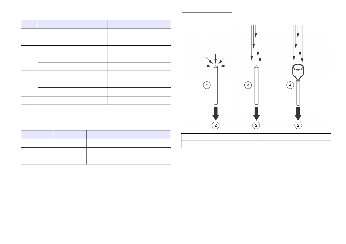
表
1 状态指示灯
颜色 指示 系统状态
绿色 闪烁(3 秒) 正常,采样
开 正常,未采样
蓝色 开 传感器故障
一次短闪烁,一次长闪烁 气流故障
闪烁 通信故障
红色 开或闪烁 计数警报
黄色 开 初始化
闪烁 计数警报
紫色 闪烁 正在使用设置实用程序
1
用户提供的中央监控软件可用于在计数警报发生时用 ModBus 协议而不是 FX
协议使黄灯闪烁。可用中央监控软件选择计数警报设置。
1
表 2 以太网指示灯
颜色 指示 Status(状态)
黄色 开 已连接
绿色 关
开
10Base-T
100Base-T
等动力取样针
为了在层流环境中实现最佳精度,
取样针中的空气速度类似于典型的垂直或水平层流环境的速度,如净化室
或净化罩。随附的等动力取样针提供相同的垂直(或水平)空气流速,以
便为仪器收集净化室层流的代表性样品。 有关用等动力取样针与不用等
动力取样针进行采样的比较,请参阅 图 2。
请始终使用本仪器随附的等动力取样针。
图 2 等动力取样针功能
1 非层流中没有取样针 3 层流中没有取样针 — 颗粒被遗漏
2 至颗粒计数器 4 等动力取样针在层流中 — 最精确
仪器配置
该仪器可进行多种配置。每种配置具有不同的部件号。图 3 显示部件号结
构。表 3 给出了部件号代码的说明。
中文
75
Page 76
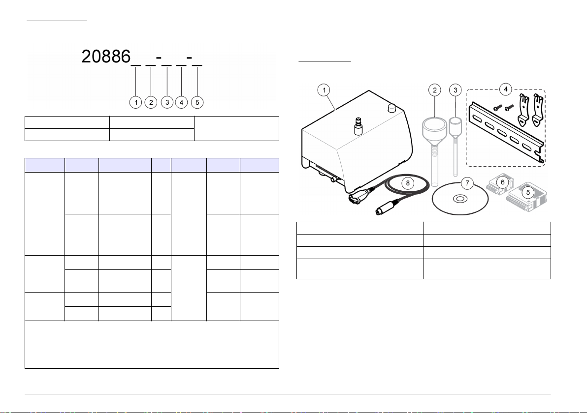
图 3 部件号结构
1 流速 3 排气位置 5 通信
2 灵敏度(最小) 4 流量测量
表
3 参数代码
参数 代码 说明 参数 代码 说明
流速
0 0.1 cfm
(用于
流量测量
0.3 µm
和 0.5 µm 灵敏
度)
1 1.0 cfm
(仅用于
0.5 µm 灵敏
度)
灵敏度
(最小)
排气位置
3 0.3 µm
通信
5 0.5 µm S
D
S
向下(按钮)
侧面
示例:具有 0.1 cfm 流速、0.5 μm 灵敏度、底部排气端口、流量测量和 RS485 通
信的仪器将具有部件号 2088605-DF-S 和 20888600-485。 第二个部件号对于标
识串行通信的类型是必要的(RS232 = 20888600-232、RS485 =
20888600-485 或脉冲 = 20888600-PLS)。 对于任何其他通信类型,第二个部件
号是不必要的。
F
带流量测
量
N
无流量测
量
E
以太网
串行
I/O
选项
A
模拟
产品组件
确保已收到所有组件。请参阅 图 4。如有任何物品丢失或损坏,请立即联
系制造商或销售代表。
图 4 仪器组件
1 MET ONE 6000 系列颗粒计数器 5 10 针连接器,带蛤壳
2 (等动力)取样针,带取样管
3 (等动力)取样针,带取样管
4 DIN 导轨安装套件 8 服务端口电缆(8 针
1
仅 1.0 cfm 设备
2
仅 0.1 cfm 设备
3
所有设备(以太网除外)
4
仅以太网
5
每次订购仅提供一根服务端口电缆。
1
2
6 5 针连接器,带蛤壳
7 设置实用程序 CD
5
连接器)
3
4
DIN 至 9 针串行
76
中文
Page 77

安装
安装指南
注 意
在开始清洁或消毒周期之前,请停止真空泵并在进气口管件上放上保护帽。
内部高温将导致仪器组件损坏。
注 意
• 壁装支架(可选)—用于永久安装。请参阅套件随附的说明。
DIN 导轨安装,请参阅 图 5 中的所示步骤。要从导轨上卸下仪器,请
有关
抬起仪器的底部。
• 将仪器安装在室内清洁、
• 如果每隔一定时间会冲洗净化室,可将仪器安装在净化室之外。仅进气
口和真空将进入净化室。或者,可将仪器放在密封箱的净化室中。将所
有管子和电缆穿过箱子连接至仪器。仪器在封闭箱中工作可能增加仪器
周围的温度并降低仪器的性能和寿命。
• 请勿在直射阳光下或热源旁边操作仪器。
• 尽可能靠近采样源安装仪器。确保距离不超过 3 m(10 ft)。长度超过
3 m(10 ft)的入口管可能导致大于 1 μm 的颗粒的损失。如果长度超过
3 m(10 ft)的入口管是必要的,请比较便携式颗粒计数器与本仪器之间
的结果。
• 保持气流始终沿向下方向。如有可能,请将仪器直接安装在采样点下面。
干燥、通风良好、温度受控且振动最小的位置。
真空系统指南
• 将真空泵放在中央位置。网络中的所有仪器必须有足够的真空。
• 使用可保持真空损失最小的分配歧管。用于真空分配的典型材料包括焊
接铜管、schedule 80 PVC 管,如 Cobolite®。
• 使用较短的管长从分配歧管提供真空到各台仪器。 在每个仪器位置使
用正确尺寸的分配阀和挂钩管件。
• 保持从真空源到仪器的接头数、弯头数和管长最小,以保持系统中的真
空损失最小。
机械安装
仪器安装
使用其中一种安装套件将仪器安装在水平表面或墙上:
• DIN 导轨套件(仪器)随附—用于从墙上快速卸下仪器。
中文
77
Page 78

图 5 DIN 导轨安装
安装取样针
请在安装之前参阅 取样针指南 第 79 以防止仪器污染并获取区域的代表
性样品。取样(等动力)针的位置对计数精度非常重要。
取样针选项
可用于取样针安装的可选套件。请参阅 图 6。
• 直接安装— 无需套件。取样针直接安装在仪器的样品进气口管件顶部
的短段管道上。 当可以将仪器放在采集样品的位置时,请使用直接安
装。使用直接安装可保持颗粒损失最小。
• 壁装,90 度— 取样针连接至不锈钢管(90 度)和墙壁支架。
• T 形墙壁支架— 取样针安装在墙壁支架中。切割管道以将取样针连接
至计数器。
• 垂直壁装— 取样针连接至不锈钢管和支架。在具有不锈钢管道的设备
上使用垂直壁装。
78
中文
Page 79

图 6 取样针安装选项
1 直接安装 3 垂直壁装
2 壁装,90 度 4 T 形墙壁支架
• 保持取样针离松动材料、灰尘、液体和喷雾至少 30 cm (12 in)。
• 保持取样针离潜在的污染源(如仪器排气扇)至少 30 cm (12 in)。
• 请勿使用本仪器监测包含 表 4 中所示物质的空气。
表 4 污染物
物质 损坏
粉末 污染传感器并导致错误结果或仪器故障
液体 污染传感器的内部光学器件并改变仪器的校准结果
注: 液体可以油珠的形式存在于空气中
烟 污染传感器
安装管道
可用管道挂钩或束线带固定管道并防止管道中的弯曲。管道中的弯曲将减
少气流和导致以下问题:
• 进气口流量的减少可能导致颗粒聚集在管道的内壁上。将无法对这些颗
粒计数。聚集的颗粒可能随机释放,这将导致计数水平的峰值。
需准备的物品:
• 进气管 — Hytrel® Bevaline、Tygon® 或等效管道
• 真空管 — Hytrel Bevaline、Tygon 或等效管道
• 管道挂钩或束线带
取样针指南
注 意
请勿使用本仪器监测包含干燥粘合剂或其他化学制品产生的蒸汽的空气。这些蒸汽
可能永久覆盖传感器光学器件或其他内部部件。
请勿使用本仪器监测包含腐蚀性蒸汽的空气。这些蒸汽将迅速导致计数器的光学或
电子设备永久损坏。
• 层流 — 每
2.3 m2(25 ft2)表面积至少安装一个取样针。
注 意
• 湍流 — 每个净化室至少安装两个取样针。
• 确保(等动力)取样针指向流向。请参阅 图 2 第 75。
1. 将进气管切割成足以将仪器连接至取样针的长度。保持管道长度最短。
确保长度不超过 3 m(10 ft)。
2. 切割真空管以将计数器连接至真空源。保持管道长度最短。
3. 在管端放上保护帽以确保在安装期间不需要的材料不会进入管道。
4. 按相距不超过 1.2 m(4 ft)的间隔给管道系上挂钩或束线带。确保管道
最小弯曲半径为 10 cm(4 in),以便空气流量不会减少。
5. 将进气管连接至仪器上的进气管件。将管道的另一端连接至随附的取
样针。
6. 将真空管连接至计数器底部(或侧面)的管件。直到净化室为采样做好
准备,才将另一端连接至真空。
中文
79
Page 80

电气安装
接线安全信息
警 告
电击致命危险。确保可轻松切断本地电源。
注 意
进行电气连接前,务必断开仪器的电源。
对仪器进行连接时,请遵从所有安装声明。
连接至电源
将外部电源 (24 VDC) 连接到 5 引脚或 10 引脚连接器。有关接线信息,
参阅 图 7 和 表 5 或 图 8 和 表 6。确保外部电源的输出电压不超过
28 VDC。
一个外部电源可连接的最多仪器数量依通信选项而定。有关详情,请联系
技术支持人员。
请参阅 图 9 中所示步骤,了解 5 针连接器的接线。请参阅 图 10 中所示步
骤,了解 10 针连接器的接线。
图 7 5 引脚连接器
图 8 10 引脚连接器
引脚 RS485 设备 RS232 设备 脉冲设备 模拟设备
请
表 6 10 引脚连接器接线
1 RS485 A —
2 RS485 B —
3 RS485 A RS232 TX
4 RS485 B RS232 RX
5 — — —
6 — —
7 — —
8
9
10
设备主电源(9–
通道 1+ 24 VDC 外部回路电源
通道 1- 通道 1 回路输出
通道 2+ 通道 2 回路输出
通道 2- 通道 3 回路输出
状态 +
公用(屏蔽接地)
28 VDC,最大 1 A)
公用
状态 -
通道 4 回路输出
—
—
5 5 引脚连接器接线
表
引脚 说明 引脚 说明
1 — 4
2 — 5
3
公用(屏蔽接地)
中文
80
设备主电源(9–28 VDC,最大 1 A)
公用
Page 81

图 9 5 引脚连接器接线 图 10 10 引脚连接器接线
中文
81
Page 82

安装串行通信
请参阅 图 8 第 80 和 表 6 第 80 以连接配有串行通信(RS485、RS232 或
脉冲)的仪器。
网络接线
可用 RS485 Modbus 或 FXB 通信将多达 32 台仪器(每台 12 K 负载)包
括在 RS485 (EIA-485) 网络中。请对串行通信使用高级电线,如 Belden
9841。 制造商建议网络的长度不超过 1200 m(3937 ft)。
图 11 显示典型的网络接线图。
图
11 网络接线
1 颗粒计数器 5 电缆
2 颗粒计数器 6 RS232 到 RS485 转换器
3 至额外的颗粒计数器 7 网络电缆
4 PC
• 长度
— 单线长度最长 100 m(328 ft)(可用中继器来增加距离)
• 中继器 — 4(最多)
• 连接器类型 — RJ45(标准以太网接线规范 T-568B)
连接模拟输出
将带有模拟输出功能的仪器连接到数据采集系统。有关接线信息,请参阅
图 8 第 80 和 表 6 第 80。
当使用 +24 VDC 电源时,如果回路有足够的输出,电源也可用作 4–20 mA
回路电源。请参阅 图 12。图 13 显示允许的总回路电阻(回路和接线组
合)的最大限制。
带有模拟输出功能的仪器发送与给定采样时间的计数成正比的 4–20 mA
信号。每次采样周期结束时,将会更新模拟输出。数据采集系统将收到该
信号。带有模拟输出功能的仪器可具有两个或四个通道规格。在网络配置
中不能使用模拟设备。
利用设置实用软件可以设置与 20 mA 信号相对应的最大计数。请参阅 配
置仪器 第 84。
当通电时,通道上的模拟输出为 4 mA。断电时或传感器或流量出现故障
时,通道上的模拟输出小于 2 mA。如果用户禁用了通道,则通道输出小于
2 mA。任何小于 4 mA(零计数值)的信号都会造成数据采集系统产生负
数,这表明仪器发出的信号有问题。
请配置中央监控软件以对小于 4 mA(零计数值)的任何信号发出警报,从
而获得必要的传感器、流量或功率损耗报警。
连接至以太网
将带有以太网通信的的仪器连接至以太网标准 10Base-T 或
网络。确保接线适用于网速以防止间歇性问题。对于本仪器,以太网标准
10Base-T 足够用来传输数据且更能容忍安装错误。
82
中文
100Base-T
Page 83

图 12 回路电源的配置
图 13 电流回路操作的最大限制
1 回路电源电压 3 超出工作范围(线下)
2 可接受的工作范围(线上) 4 总回路电阻的最大限制
1 公用回路电源的配置 5 公用
2 单独回路电源的配置 6 4–20 mA 收集系统
3 24 VDC 回路电源 7 24 VDC 电源
4 + 回路电源 8 + 电源
启动
清洁外表面
注 意
切勿直接用液体或蒸汽双氧水 (VHP) 流喷射仪器。当液体溶液进入计数器流动路
径或电子设备时,传感器会损坏。
勿让消毒化学蒸汽进入仪器外壳和与仪器电子设备接触。
用异丙醇 (IPA) 弄湿的无绒纸巾擦拭外表面。 采样(等动力)探头可用高
压蒸汽处理进行清洁。
清洁内表面
使用零计数过滤器清除仪器内表面和进气管的污染物,如颗粒、绒毛或灰
尘。当计数变为零时,内表面和进气管变干净。
注 意
中文
83
Page 84

需准备的物品:零计数过滤器
1. 将零计数过滤器连接到进气管。
零计数过滤器可防止任何外部颗粒进入仪器。
2. 开始采样并让仪器工作至少 30 分钟。请参阅 手动操作 第
3. 按 5 分钟间隔监测室内空气直至颗粒计数为 0–1。
可选:要记录数据,请将“采样定时:采样”设置设为 5 分钟。请参阅 配
置仪器 第 84。
4. 如果在九或十个 5 分钟采样周期之后颗粒计数不变为 0–1,请通宵净化
仪器。请参阅 吹扫仪器 第 84。
88。
吹扫仪器
吹扫后使颗粒计数达到 0–1 个。通常,在测试之前进行吹扫以确保具有仪
器的基线参考。
1. 从进气管的取样针端去除大约 2.5 cm(1 in)的管道,以去除任何拉伸
或刮伤部分。
2. 将的零计数过滤器连接到进气管。
3. 让仪器工作 24 小时。
4. 如果 24 小时之后颗粒计数未显示为 0–1,则检查颗粒源是否是进气管。
a. 将零计数过滤器直接安装在进气口管件上。
b. 再让仪器工作 15 分钟。
c. 监控室内空气 5 分钟并记录结果。最多执行此步骤四次,直到 5 分
钟采样的颗粒计数为 0–1。
d. 如果颗粒计数显示为 0–1,则进气管为颗粒源。替换进气管
e. 如果颗粒计数未变成 0–1,请联系技术支持人员。
操作
在初始配置之后,必要时可通过直接连接至 PC 或通过 ModbusTCP 连接
更改配置。对于通过网络的配置,只可更改 LAN 设置。请参阅 通过网络
配置 LAN 设置。 第 86。
连接至 PC
需准备的物品:
• 设置实用程序 CD
• 服务端口电缆
• 装有 Windows® 2000 专业版、Windows XP 专业版、Windows Vista
(32 位)、Windows 7(32 位或 64 位 XP 仿真模式)的 PC
• USB 至 RS232 适配器(如果 PC 没有 RS232 端口)
1. 确保 PC 上安装了 Microsoft .Net Framework。如果未安装,请打开设
置实用程序 CD 上的 dotnetfx.exe 文件并安装该应用程序。
注: 用户必须作为管理员登录
2. 从设置实用程序 CD 复制 SetupUtility.exe 文件并将其粘贴到 PC。
3. 将服务端口电缆连接到仪器上的服务端口和 PC 上的 COM 端口。
PC
。
配置仪器
使用设置实用软件以配置每台仪器上保持的参数。 当仪器通电时,它会寻
找新配置。如果找不到新配置,将使用先前保存的配置。
1. 打开 PC 上安装的 SetupUtility.exe 文件以启动设置实用程序。
2. 选择“基本设置”选项卡。
3. 找到窗口右侧的“端口”字段。选择 PC 上连接至仪器的 COM 端口。
4. 单击读取仪器。 实用程序读取仪器上保存的数据。
5. 确保“仪器信息”部分的数据正确(型号、通信选项、固件版本和通信地
址,如果适用的话)。
配置
为了进行初始配置,请将仪器连接至 PC。
中文
84
Page 85

6. 在“常规”部分,选择设置。
选项 说明
计数模式 设置计数模式。请勿影响模拟设备的模拟输出。
差别 — 为每个通道显示的颗粒计数是每个通道规格的计数。
累积(默认值)— 为每个通道显示的颗粒计数是每个通道规格加
更大通道规格的计数。例如,如果通道为 0.3 µm,则计数中包括
0.3 µm 和更大尺寸的颗粒。
采样定时:采样设置每次采样的时间长度(默认值 = 00:01:00 = 1 分钟)。
采样定时:保持设置进行采样之后数据采集停止的时间长度(默认值 =
计数周期 设置数据采集停止和保持时间开始之前进行的采样次数(0 = 连
从地址/采样
点 ID
通信超时 设置通信故障之后通信 (Comm) 警报发生之前的秒数。要禁用
取样点名称 为仪器设置唯一的标识符。
系统日期/时间设置日期 (YYYY/MM/DD) 和时间(HH:MM:SS,24 小时格式)。
移动累积计数设置加在一起并显示在通道 3 和通道 4 中的通道 1 或通道 2 的
存储部分记录让部分采样数据可以保存到缓冲区。当采样在完成之前停止时,
温度单位 °C 将温度单位从华氏(默认值)更改为摄氏。
远程 LCD 不可用(禁用)
计数警报 设置每个通道将触发计数警报的最小颗粒数。
00:00:00)。
续采样)。
请勿更改(默认值 = 1)。
通信警报,请设置为 0。 对于具有模拟输出功能的仪器,请设置
为 0。
采样计数。通道 3 显示通道 1 的累积计数。 通道 4 显示通道
2 的累积计数。
会出现部分采样数据。
要设置通道规格,请选择“数据显示”选项卡。请参阅 图 15
第 89。
选项 说明
取样模式 设置取样模式。
自动 — 当仪器通电时,采样数据采集自动启动。
手动 — 当仪器通电时,采样数据采集不自动启动。必须手动启
动采样数据采集。请参阅 手动操作 第 88。
注: 具有模拟输出的以太网设备不能设置为“手动”,因为没有与
中央监控软件的双向通信。这些设备总是用“自动”模式启动。
流量单位 设置空气流量单位。选项:CFM(立方英尺/分钟)或 LPM
(升/分钟)。
7. 如果可选外部灯栈连接至仪器,请使用“诊断”部分将状态指示灯设置为
其中一种颜色闪烁或不闪烁以标识接线正确。
注: 此操作不会保存诊断设置,且它们不会影响仪器工作。
8. 对于具有模拟输出的设备,请在“模拟”部分更改 4–20 mA 模拟输出的
设置。
选项 说明
满刻度 设置每个通道对应于 20 mA 输出信号的颗粒计数(默认值 = 1000)。
零颗粒计数对应于 4 mA 输出信号。
注: 计数警报不会报告至中央监控软件。如有需要,可配置中央监控
软件以触发计数警报。
输出状态设置输出状态。对于正确操作,请设置为“正常”。
零 — 将输出保持在 4 mA。
跨度 — 将输出保持在 20 mA。
9. 对于串行通信(仅 RS485 设备),请更改“串行”部分的通信设置。选
项:FXB、Modbus、R48XX 兼容、FXB1。 如果选择了
Modbus,请
输入从地址。当地址为 31 或以下时,请使用仪器底部的编码开关设置
地址。请参阅 使用 Modbus RTU 协议的 RS485 串行输出 第 87。
注: 如果输入了
32
或更高的地址,将忽略编码开关设置并使用输入的值。
10. 对于脉冲通信(仅 RS485 设备),请在“脉冲”部分为通道 2 脉冲输出
选择通道规格(默认值 = 计数通道 2)。 通道 1 脉冲输出总是对应于
通道 1 颗粒尺寸。
11. 对于以太网通信(仅以太网设备),请参阅 配置以太网设置 第 86。
12. 单击保存设置以保存更改。
中文
85
Page 86

配置以太网设置
1. 对于没有模拟输出功能的以太网设备,请更改以太网部分的以太网设
置。只应由网络专业人士更改以太网设置。
选项 说明
MAC 媒体访问控制
DHCP/APIPA 通过连接至 DHCP 服务器启用或禁用静态或动态 IP 地址(默
认值 = 禁用)。当启用时,通电之后仪器会自动获取 IP 地址
和子网掩码。
如果 DHCP 服务器不可用,仪器将使用 APIPA 获取 IP 地址和
子网掩码。
• APIPA IP 地址范围:169.254.0.0 至 169.254.255.255
• 子网掩码: 255.255.0.0(B 类网络)
IP 地址 对于静态 IP 地址,每台基于 LAN 的仪器必须拥有唯一的 IP 地
址。 范围:169.254.0.0 至 169.254.255.255(默认值 =
169.254.1.2)。
子网掩码 用单个软件包(即 FMS)通信的同类型仪器使用同一子网掩码
(默认值 = 255.255.0.0)。 范围:0 至 255,仅整数。
服务器端口 ModbusTCP 服务器侦听端口(默认值 = 502)。 范围:0 至
65535,仅整数。
客户端端口 不可用(禁用)
网关 到另一网络的路由器或接入点(默认值 = 169.254.1.5)
远程服务器 IP 不可用(禁用)
以太网协议 将以太网协议设置为 Modbus 或 FXB。
— 显示唯一的永久硬件地址(只读)
2. 对于具有模拟输出功能的以太网设备,请参阅通过网络配置 LAN 设置。
第 86 以配置以太网设置。
3. 单击保存设置以保存更改。
通过网络配置 LAN 设置。
1. 在设置实用软件中,选择 LAN 设置选项卡。该软件查找 LAN 仪器。显
示找到的 LAN 仪器。
2. 选择仪器以显示 LAN 仪器设置。
3. 更改
LAN 设置。请参阅 配置以太网设置 第 86 中的选项表。
4. 单击保存设置以保存更改。
进行模拟输出测试
对于带有模拟输出功能的仪器,请进行模拟输出测试。
1. 将模拟输出连接至数据采集系统的负载电阻器。
注: 作为替代,在模拟输出两端安装一组具有
的负载电阻器。通常使用
100、250 或 500Ω
2. 让微小数量的颗粒流经仪器以获取测试通道的计数。
注: 获取计数的一种方法是使用零计数过滤器,并在过滤器与仪器之间的管道中
放一针孔。
3. 在设置实用软件的“基本设置”选项卡上,临时设置:
• 计数周期 — 1
• 采样定时:保持 — 10 秒或更长
4. 单击保存设置。
5. 选择“数据显示”选项卡,然后单击监控(如果显示)以便当进行每次采
样时,显示的数据可连续更新。
6. 单击采样(如果显示)以启动采样。
7. 当状态值从“计数”变为“停止”时,测量每个通道的负载电阻器两端的电
压。还请记下显示屏中为每个通道显示的计数。
8. 使用下面的等式根据显示的计数计算期望的电压。确保测得和计算的
电压一致。
电压 = (((SC ÷ FC × 16) + 4) ÷ 1000) × RL
其中:
SC = 采样周期结束时的采样计数
FC = 满刻度通道计数。请参阅设置实用软件中的模拟设置。
RL = 负载电阻器的值 (Ω)
使用 100、250 和 500Ω 电阻器时,如果满刻度通道计数为 1000,则
期望输出电压显示在 表 7 中。
9. 要再次执行测试,请执行步骤 7–8。
10. 对于具有流量监控器的设备,请从仪器中临时取出中央真空。
11. 当流量警报激活时,请测量每个通道的负载电阻器两端的电压。
0.1%
精确度和至少
值的负载电阻器。
0.25 W
容量
86
中文
Page 87

12. 使用下面的等式以计算期望的电压。确保测得和计算的电压一致。
电压 = < (0.002 × RL)
其中:RL = 负载电阻器的值 (Ω)
示例:对于 100 Ω 电阻器,电压应低于 0.20 V。
13. 在“基本设置”选项卡上,将设置改回先前的值。
14. 单击保存设置。
表 7 使用 100、250 和
采样计数 100 Ω 250 Ω 500 Ω
0 0.40V 1.00V 2.00V
100 0.56V 1.40V 2.80V
200 0.72V 1.80V 3.60V
300 0.88V 2.20V 4.40V
400 1.04V 2.60V 5.20V
500 1.20V 3.00V 6.00V
600 1.36V 3.40V 6.80V
700 1.52V 3.80V 7.60V
800 1.68V 4.20V 8.40V
900 1.84V 4.60V 9.20V
1000 2.00V 5.00V 10.00V
500Ω 电阻器时的输出电压
使用 Modbus RTU 协议的 RS485 串行输出
带有 RS485 Modbus 通信选项的仪器使用工业标准 Modbus RTU 协议。
在此通信模式下
当进行 ModbusTCP 连接时,用户可使用 Modbus 寄存器映射中的所有配
置选项。有关 Modbus 寄存器映射,请参阅公司网站。编写使用 Modbus
RTU 协议通过这些寄存器与仪器通信的驱动程序。
RS485 串行网络电路可为最多 32 台仪器和一台控制计算机提供通信。每
次仅一台仪器可传输数据。每台仪器必须具有唯一的仪器地址。
,一系列寄存器保存有关测量结果和操作参数的数据。
1. 将仪器翻过来。DIP 开关在仪器的底部。
2. 更改 DIP 开关设置,以为仪器选择唯一的网络地址。 请参阅 表 8。
注: 地址
0
只能与
FXB
址。 如果使用
协议一起使用。地址
Modbus
协议设置了地址 0,则仪器将使用地址 1。
0
保留用作
Modbus RTU
的广播地
表 8 网络地址的 DIP 开关设置
网络地址 开关 1 开关 2 开关 3 开关 4 开关 5
0 关 关 关 关 关
1 开 关 关 关 关
2 关 开 关 关 关
3 开 开 关 关 关
4 关 关 开 关 关
5 开 关 开 关 关
6 关 开 开 关 关
7 开 开 开 关 关
8 关 关 关 开 关
9 开 关 关 开 关
10 关 开 关 开 关
11 开 开 关 开 关
12 关 关 开 开 关
13 开 关 开 开 关
14 关 开 开 开 关
15 开 开 开 开 关
16 关 关 关 关 开
17 开 关 关 关 开
18 关 开 关 关 开
19 开 开 关 关 开
中文
87
Page 88

表 8 网络地址的 DIP 开关设置 (续)
网络地址 开关 1 开关 2 开关 3 开关 4 开关 5
20 关 关 开 关 开
21 开 关 开 关 开
22 关 开 开 关 开
23 开 开 开 关 开
24 关 关 关 开 开
25 开 关 关 开 开
26 关 开 关 开 开
27 开 开 关 开 开
28 关 关 开 开 开
29 开 关 开 开 开
30 关 开 开 开 开
31 开 开 开 开 开
使用 FXB 协议的
RS485 串行输出
带有 RS485 FXB 通信选项的仪器使用工业标准 FXB 协议。有关 FXB 协
议信息,请参阅公司网站。
脉冲通信
当检测到颗粒时,带有脉冲通信选项的仪器将发送 8-µs 脉冲信号。请参阅
图 14。外部脉冲计数器或数据采集系统接收脉冲信号并将脉冲计作颗粒。
带有脉冲通信的仪器具有两个脉冲输出通道(通道 1 和通道 2)。 当检测
到通道 1 颗粒尺寸时,通道 1 将发送脉冲信号。当检测到用户选择的通道
规格时,通道 2 将发送脉冲信号。
当有活动警报时,脉冲通信包括从低到高的状态输出信号。在网络配置中
不能使用脉冲通信。
将脉冲通信仪器的网络地址设置为 1。 请参阅 表 8 第 87。
可用以下两种计数模式之一发送脉冲信号:
• 差别模式(默认)— 当颗粒在第一个与第二个通道规格阈值之间时,
在
通道 1 上发送信号。当颗粒大于用户选择的通道规格阈值时,在通道
2 上发送信号。
• 累积模式— 当颗粒大于第一个或第二个通道规格阈值时,在通道 1 上发
送信号。当颗粒大于用户选择的通道规格阈值时,在通道 2 上发送信号。
图 14 差别与累积计数模式对比示例
1 从计数器发送的脉冲信号 4 通道 1
2 差别与累积模式下的数据传输 5 差别计数 — 一个
3 通道 2 6 累积计数 — 三个 0.3 µm 和两个
5.0 µm 颗粒
5.0 µm 颗粒
0.3 µm 和两个
手动操作
使用设置实用软件利用直接 PC 连接或通过 LAN 连接手动操作仪器。
1. 打开 SetupUtility.exe 文件以启动设置实用软件。
2. 选择“数据显示”选项卡。有关显示的数据,请参阅 图 15。
88
中文
Page 89

3. 使用按钮操作仪器。
注: 按钮会随系统状态变化。
选项 说明
监视器 实时连续显示更新的数据。
停止监视器 停止显示的数据的变化。
样品 开始样品采集。采样按照“基本设置”选项卡中的设置进行。
如果仪器处于不活动模式,将仪器变为活动模式。
停止计数 停止样品采集。
活动模式 将内部激光器设置为“开”。启用警报。
不活动模式 将内部激光器设置为“关”。禁用警报。
显示缓冲的数据 显示上次完成的采样的数据。当完成每次采样时更新。
下载缓冲区 将缓冲区中的数据记录的副本保存到 PC 作为文本 (CSV) 文
件。
擦除存储器 擦除缓冲区中的所有数据记录。
图
15 实时数据显示
1 活动警报(传感器、流量、通信、计
数1)
2 通道规格和颗粒计数 8 为样品采集的空气体积(cfm 或
3 采样时间 9 可选相对湿度 (RH) 和温度传感器的
4 上次采样开始时间和日期 10 不可用
5 系统状态 11 校准电压—标识传感器光学器件的
6 仅维修使用
1
当计数警报发生时,高颗粒计数显示为红色。
7 空气流量(cfm 或 L/min)
L/min)
值
清洁度
中文
89
Page 90

校准
用户无法校准仪器。如需校准仪器,请联系制造商。
维护
警 告
注 意
表
9 维护计划
X
X
存在人身伤害危险。只有合格的专业人员,才能从事手册此处所述的工作。
请勿拆卸仪器进行维护。如果必须清洁或维修内部组件,请联系制造商。
维护计划
表 9 显示建议的维护任务计划。设施要求和工作条件可能会增加某些任务
的频率。
任务 1 年
替换进气管 第 90
校准 第 90
替换进气管
定期替换进气管以防止管壁上的有机增长或无机颗粒污染。污染可能导致
虚假的高颗粒计数。
制造商建议每年至少更换一次生命科学和医药制造净化室中的典型 FMS
装置的进气管。
90
中文
Page 91

目次
仕様 ページの 91 スタートアップ ページの 104
総合情報 ページの 92 操作 ページの 105
設置 ページの 96 メンテナンス ページの 112
仕様
この仕様は予告なく変更されることがあります。
仕様 詳細
寸法
(W × D ×
H)
筐体 304 ステンレス鋼
光源 Long Life Laser™ ダイオード、クラス
重量
汚染度
取り付けカテ
ゴリ
保護クラス
電源 9 ~ 28 VDC (電源: クラス 2 有限電源、< 150 VA)
消費電力 (最大)シリアルユニット/パルスユニット: 3.3 W、イーサネットユニッ
動作周囲温度 5 ~ 40 °C、最高性能: 10 ~ 32 °C
保管温度 –40 ~ 70 °C
湿度 作動時および保管時: 相対湿度 5 ~ 95%、結露なきこと
高度 最大 2000 m
13.56 x 8.93 x 12.06 cm
3B レーザー
0.82 kg
2
I
III
ト: 4.3 W、アナログ: 3.5 W、最大 1 A
仕様 詳細
ポートサイズ モデル
出力信号オプ
ション
データメモリー1000 サンプル/レコード (バッファーがいっぱいになった場合
サンプル流量 モデル
インレット圧力周囲圧力 ~ 2.5 mmHg 負圧
真空要件 ≥ 406 mmHg (最小負圧)、
範囲 モデル 6003: 0.3 μm ~ 10.0 μm (0.1 cfm (2.83 リットル/分))
最小可測粒径 モデル
カウント効率 モデル
6003、6005: 吸気チューブ - 内径 0.32 cm 用バーブ継手、
排気チューブ - 内径 0.64 cm 用バーブ継手
モデル 6013、6015: 吸気チューブ - 内径 0.64 cm 用バーブ継手、
排気チューブ - 内径 0.64 cm 用バーブ継手
パルス、アナログ
たは FXB 通信プロトコル) (ネットワークなし)、シリアル
RS485 (Modbus RTU または FXB 通信プロトコル)、イーサネッ
ト (ModbusTCP プロトコル)
は、古いレコードから順に上書き)
6003、6005: 0.1 cfm (2.83 Lpm) ± 5%
モデル 6013、6015: 1.0 cfm (28.3 Lpm) ± 5%
態で各装置で測定。
モデル 6005: 0.5 μm~ 10.0 μm (0.1 cfm (2.83 リットル/分))
モデル 6013、6015: 0.5 μm~ 10.0 μm (1.0 cfm (28.3 リット
ル/分))
6003: 0.3 μm (0.1 cfm (2.83 リットル/分))
モデル 6005: 0.5 μm (0.1 cfm (2.83 リットル/分))
モデル 6013: 0.3 μm (1.0 cfm (28.3 リットル/分))
モデル 6015: 0.5 μm (1.0 cfm (28.3 リットル/分))
6003: 0.3 μm で 50% (± 20%)、(最小感度の 1.5 倍で
100% ± 10%)1。
モデル 6005、6013、6015: 0.5 μm で 50% (± 20%)、(最小感度の
1.5 倍で 100% ± 10%)1。
4–20 mA、シリアル RS232 (Modbus RTU ま
すべての装置で気流が発生している状
日本語
91
Page 92

仕様 詳細
同時計数ロス モデル
偽計数 5 分で 1 以下
認証
1
ISO21501-4 に完全準拠
6003、6005 (すべての出力オプション): 140,000,000 粒
子/m3 (4,000,000 粒子/ft3)で 10%
モデル 6013、6015 (パルスを除くすべての出力オプション):
20,000,000 粒子/m3 (566,000 粒子/ft3) で 10%
CE
総合情報
いかなる場合も、製造元は、例えそのような損害が生じる可能性につい
て報告を受けていたとしても、本マニュアルに含まれるいかなる瑕疵ま
たは脱落から生じる直接的、間接的、特定、付随的または結果的に生じ
る損害に関して責を負いません。製造元は、通知または義務なしに、随
時本マニュアルおよび製品において、その記載を変更する権利を留保し
ます。改訂版は、製造元の Web サイト上にあります。
拡張マニュアル バージョン
追加情報はこのマニュアルの拡張バージョンの CD を参照してくださ
い。
安全情報
告 知
メーカーは、本製品の目的外使用または誤用に起因する直接損害、偶発的損害、
結果的損害を含むあらゆる損害に対して、適用法で認められている範囲で一切責
任を負わないものとします。ユーザーは、適用に伴う危険性を特定したり、装置
が誤作動した場合にプロセスを保護するための適切な機構を設けることに関し
て、全責任を負うものとします。
この機器の開梱、設定または操作を行う前に、このマニュアルをすべて
よく読んでください。危険および注意の注意事項に注意を払ってくださ
い。これを怠ると、オペレータが重傷を負う可能性、あるいは機器が損
傷を受ける可能性があります。
本装置に備わっている保護機能が故障していないことを確認します。本
マニュアルで指定されている以外の方法で本装置を使用または設置しな
いでください。
危険情報の使用
危 険
回避しなければ死亡または重傷につながる、潜在的または切迫した危険な状況を
示します。
避けない場合、死亡事故や負傷が起こるかも知れない危険な状況を示します。
軽傷または中傷事故の原因となる可能性のある危険な状況を示しています。
回避しなければ、装置の損傷を引き起こす可能性のある状況を示します。 特に注
意を要する情報。
警 告
注 意
告 知
使用上の注意ラベル
装置に取り付けてあるラベルとタグをすべてお読みください。これを怠
ると、人身傷害や装置の損傷につながるおそれがあります。測定器に記
載されたシンボルについては、使用上の注意が記載されたマニュアルを
参照してください。
このシンボルが測定器に記載されている場合、操作用の指示マニュア
ル、または安全情報を参照してください。
このシンボルが製品筐体またはバリア上に表示されている場合、感電
の危険があり、場合によっては感電死の原因となる恐れのあることを
示しています。
92
日本語
Page 93

このシンボルは、機器内でレーザーデバイスが使用されていることを
示します。
このシンボルが表示された電気機器は、欧州廃棄システムにより
2005 年 8 月 12 日以降の廃棄処分が禁じられています。欧州地域規
制および国内規制
ーザーは古くなったまたは使い切った機器をメーカーに無償返却す
る必要があります。
注: リサイクルのために返却する際には、機器の製造者または販売業者に連絡を
取り、使用済みの機器、製造者に供給された電気付属品、ならびにすべての補助
品を適切に廃棄するための指示を受けてください。
(EU 指令 2002/96/EC) に従い、欧州の電気機器ユ
レーザーの安全性に関する情報
この装置は
9022243-029)。開くと、不可視レーザー光が出ます。ビームに直接触れ
ないようにしてください。内部コンポーネントの取り扱いは必ず工場認
定技術者が行うようにしてください。
この製品は、IEC/EN 60825-1 および 21 CFR 1040.10 に準拠しています
(2007 年 6 月 24 日付の Laser Notice No. 50 に準じた逸脱を除く)。
、クラス 1 のレーザー製品です(CDRH Accession No.
これらの規格への準拠に責任を持つ当事者による明示的承認を伴わなず
にこの装置に対する改変または改造を行うと、ユーザーはこの機器を使
用する権限を失う可能性があります。この装置は、FCC 規則のパート
15 に従って、
クラス A のデジタル機器の制限に準拠することが試験によ
って確認されています。これらの制限は、この機器が商用の環境で使用
されたときに、有害な干渉から適切に保護することを目的に設定されて
います。この機器は、無線周波数エネルギーを生成および使用するもの
で、取り扱い説明書に従って取り付けおよび使用しない場合にはそれを
放射する場合があり、無線通信に対して有害な干渉を発生させる可能性
があります。住宅地域における本装置の使用は有害な電波妨害を引き起
こすことがあり、その場合ユーザーは自己負担で電波妨害の問題を解決
する必要があります。以下の手法が干渉の問題を軽減するために使用可
能です。
1. 装置から電源を取り外して、電源が干渉源かどうかを確認します。
2. 装置が干渉を受けている装置と同じコンセントに接続されている場
合は、装置を別のコンセントに接続してください。
3. 妨害を受けている装置から本装置を離します。
4. 干渉を受けるデバイスの受信アンテナの位置を変更します。
5. 上記の手法を組み合わせてみます。
取得認証
カナダの障害発生機器規則、IECS-003、クラス A:
テスト記録のサポートはメーカーにあります。
このクラス A デジタル装置はカナダの障害発生機器規則の要件をすべて
満たします。
Cet appareil numèrique de classe A répond à toutes les exigences de la
réglementation canadienne sur les équipements provoquant des
interférences.
FCC PART 15、クラス 「A」 限度値
テスト記録のサポートはメーカーにあります。この機器は FCC 規則の
パート 15 に準拠します。運転は以下の条件を前提としています:
1. この装置が有害な干渉の原因とならないこと。
2. この装置が望ましくない動作の原因となる可能性のあるいかなる干
渉にも対応しなければなりません。
製品の概要
この装置は、レーザーダイオード光源と集光光学系によって浮遊粒子を
カウントします。図 1 を参照してください。接続されている外部真空シ
ステムによって、クリーンルームの空気がパーティクルカウンターに吸
引されます。
複数の装置をクリーンルーム内の異なる場所に設置して、空気品質を監
視することができます。カウントデータはユーザーが用意したセントラ
ルモニタリングソフトウェアに、適切な通信プロトコル経由で送信され
ます。セントラルモニタリングソフトウェアは、装置を遠隔操作するの
に使用します。
センサの流路は、VHP による標準的なクリーンルームの殺菌/洗浄サイク
ルで使用できるよう、過酸化水素ガス (VHP) に対する耐性を備えていま
す。
日本語
93
Page 94

図 1 製品の概要
1 電源入力および通信コネクタ、10 ピ
1
ン
2 真空源用継手 (クイックコネクト継手)8 真空源用継手 (代替位置)
3 サンプル吸気用継手 9 接続インジケーターライト2 (表 2)
4 ステータスインジケーターライト
(表 1)
5 サービスポートとオプションのラ
イトスタック用ポート
6 DIP スイッチ、ネットワークアドレ
1
ス
1
イーサネットユニットを除くすべてのユニット
2
イーサネットユニットのみ
7 相対湿度 (RH)/温度センサ用ポート
10 イーサネット RJ45 コネクタ
11 電源入力コネクタ、5 ピン
2
2
表 1 ステータスインジケーターライト
色 表示 システムのステータス
緑 点滅
青 点灯 センサ故障
赤 点灯または点滅 カウントアラーム
黄色 点灯 初期化
紫色 点滅 セットアップユーティリティ使用中
1
(3 秒) 正常、サンプリング中
点灯 正常、サンプリング停止中
短い点滅 1 回、長い点滅 1 回 気流異常
点滅 通信エラー
点滅 カウントアラート
ユーザーが用意したセントラルモニタリングソフトウェアを使って、FX プロ
トコルではなく、ModBus プロトコルによってカウントアラートが発生したと
きに黄色のライトが点滅するように設定することができます。カウントアラ
ート設定は、セントラルモニタリングソフトウェアで選択します。
1
表 2 イーサネットインジケーターライト
色 表示 ステータス
黄色 点灯 接続済み
緑 消灯
点灯
10Base-T
100Base-T
等速吸引プローブ
層流環境で最高の精度を得るためにも、必ずこの装置に付属されている
等速吸引プローブを使用してください。プローブ内の空気流速は、クリ
ーンルームやクリーンフードなどの典型的な垂直または水平層流環境の
流速とほぼ同じです。付属の等速吸引プローブでは、装置がクリーンル
ームの層流の代表的サンプルを採取できるように、
方向) の流速は同じになります。等速吸引プローブを使用した場合と使
垂直方向 (または水平
94
日本語
Page 95

用しない場合のサンプリングの比較については、図 2 を参照してくださ
い。
図 2 等速吸引プローブの機能
図 3 部品番号の構造
1 流量 3 排気位置 5 通信
2 感度 (最小) 4 流量測定
表
3 パラメーターコード
パラメーターコード 説明 パラメーターコード 説明
1 非層流でプローブなし 3 層流でプローブなし。粒子を逃す
2 パーティクルカウンターへ 4 層流で等速吸引プローブあり。最
も正確
装置の構成
この装置はさまざまな構成で使用することができ、構成によって部品番
号が異なります。図 3 に部品番号の構造を示し、表 3 に部品番号コード
の説明を示します。
流量
0 0.1 cfm
(感度
および 0.5 µm
用)
1 1.0 cfm
(感度 0.5 µm
専用)
0.3 µm
流量測定
F
N
流量測定
機能あり
流量測定
機能なし
日本語
95
Page 96

表
3 パラメーターコード (続き)
パラメーターコード 説明 パラメーターコード 説明
図 4 装置のコンポーネント
可測粒径
(最小)
排気位置
例: 流量 0.1 cfm、感度 0.5 μm、排気ポート裏面、流量測定機能あり、RS485 通
信付き装置の部品番号は 2088605-DF-S と 20888600-485 になります。2 番目
の部品番号は、シリアル通信のタイプを特定するのに必要です (RS232 =
20888600-232、RS485 = 20888600-485、パルス = 20888600-PLS)。2 番目の部
品番号は、他の通信タイプでは必要ありません。
3 0.3μm
5 0.5μm S
D
S
下向き
側面
(裏側)
通信
E
A
イーサネ
ット
シリアル
入出力オ
プション
アナログ
製品コンポーネント
すべてのコンポーネントがあることを確認します。図 4 を参照してくだ
さい。コンポーネントが不足していたり損傷していたりした場合は、直
ちに HACH Japan または弊社販売代理店にお問い合わせください。
1 MET ONE 6000 シリーズパーティ
クルカウンター
2 チューブ付きサンプル (等速吸引)
3 チューブ付きサンプル (等速吸引)
4 DIN レール取り付けキット 8 サービスポートケーブル (8 ピン
1
2
3
4
5
1
プローブ
2
プローブ
1.0 cfm ユニットのみ
0.1 cfm ユニットのみ
イーサネットユニットを除くすべてのユニット
イーサネットユニットのみ
1 注文につきサービスポートケーブル 1 本のみ付属
5 クラムシェル型 10 ピンコネクタ
6 クラムシェル型 5 ピンコネクタ
7 セットアップユーティリティ CD
DIN / 9 ピンシリアルコネクタ)
設置
取り付けのガイドライン
3
4
5
96
日本語
告 知
洗浄または殺菌サイクルを開始するまで、真空ポンプを停止し、吸気継手にカバ
ーを取り付けてください。
Page 97

告 知
内部温度が高いと、装置のコンポーネントが損傷する可能性があります。
• 装置は、屋内の清潔で乾燥した、換気が良好で温度制御され、振動の
少ない場所に設置してください。
• クリーンルームを定期的に洗浄する場合は、装置をクリーンルームの
外に設置し、吸気チューブと真空チューブのみがクリーンルームに入
るようにしてください。または、装置をクリーンルーム内の密閉され
たボックス内に設置し、ボックスを通すようにして、すべてのチュー
ブとケーブルを装置に接続してください。密閉されたボックス内で装
置を作動させると、装置周囲の温度が上昇し、装置の性能および寿命
が低下することがあります。
• 直射日光の当たる場所、または熱源の近くで装置を作動させないでく
ださい。
• 装置はできるだけサンプル供給源の近くに設置してください。距離が
3 m 以下であることを確認してください。吸気チューブの長さが 3 m
を超えていると、1 μm より大きな粒子を採取できなくなる可能性があ
ります。吸気チューブを 3 m を超える長さにする必要がある場合は、
ポータブルパーティクルカウンターとこの装置の結果を比較してくだ
さい。
• 気流が常に下向きになるようにしてください。可能な場合は、装置を
サンプリング位置の真下に設置してください。
真空装置のガイドライン
• 真空ポンプは中心となる位置に設置してください。ネットワーク内の
すべての装置で十分な負圧を得られる必要があります。
• 負圧損失を最小限に抑えることが可能な分配マニホールドを使用して
ください。負圧分配で一般的に使用する材質として、ろう付け銅管、
スケジュール 80 PVC パイプ、または Cobolite® などのチューブがあ
ります。
• 分配マニホールドから各装置に負圧を供給するチューブの長さは短く
してください。各装置の設置場所では、適切なサイズの分配バルブお
よびバーブ継手を使用してください。
• システムの負圧損失を最小限にするためにも、ストレートアダプター
やエルボーの数、および真空源から装置へのチューブの長さを最小限
に抑えてください。
設置
装置の取り付け
装置を水平な場所に設置するか、次のいずれかの取り付けキットを使用
して壁面に取り付けます。
•
DIN レールキット (装置に付属) - 装置を壁面からすばやく取り外せる
ようにする場合に使用します。
• 壁取り付けブラケット (オプション) - 恒久的に設置する場合に使用し
ます。キットに付属の取扱説明書を参照してください。
DIN レールを使用して取り付ける場合は、図 5 の手順を参照してくださ
い。装置をレールから取り外すには、装置の下部を持ち上げます。
日本語
97
Page 98

図 5 DIN レール取り付け
サンプルプローブの取り付け
取り付け前にサンプルプローブのガイドライン ページの 99 を参照し
て、装置に汚れがつかないようにし、領域の代表サンプルをとるための
方法を確認してください。サンプル (等速吸引) プローブの位置は、カウ
ントの精度に重要です。
サンプルプローブのオプション
サンプルプローブ設置用のオプションキットも用意しています。図 6 を
参照してください。
• 直接取り付け - キットは不要です。サンプルプローブは、装置のサン
プル吸気継手の上に直接取り付けた短いチューブに取り付けます。直
接取り付け設置方法は、サンプル採取場所に装置を設置できる場合に
使用します。粒子のロスを最小限に抑えるためには、直接取り付け設
置方法を使用してください。
• 壁取り付け、90 ° - プローブは、
とウォールブラケットに接続されています。
• T タイプウォールブラケット - サンプルプローブは、ウォールブラケ
ットに取り付けます。チューブを切断してプローブをカウンターに接
続します。
• 垂直壁取り付け - サンプルプローブは、ステンレススチール製チュー
ブとブラケットに接続されています。垂直壁取り付け設置方法は、ス
テンレススチール製チューブの機器で使用します。
ステンレススチール製チューブ (90 °)
98
日本語
Page 99

図 6 サンプルプローブの設置方法
1 直接取り付け 3 垂直壁取り付け
2 壁取り付け、90 ° 4 T タイプウォールブラケット
サンプルプローブのガイドライン
告 知
この装置は、乾燥粘着剤や他の化学薬品から発した気体が含まれた空気を監視す
るのに使用しないでください。これらの気体によりセンサの光学系や他の内部部
品が覆われて、除去できなくなってしまう可能性があります。
この装置は、腐食性のある気体が含まれた空気を監視するのに使用しないでくだ
さい。これらの気体により、光学系やカウンターの電子部品はすぐに永久的な損
傷を受けてしまいます。
告 知
• 乱流 - 各クリーンルームに、サンプルプローブを少なくとも 2 つ設置
します。
• サンプル (等速吸引) プローブは、
気流と同じ向きになるように設置し
てください。図 2 ページの 95 を参照してください。
• サンプルプローブは、遊離物質、埃、液体および飛沫から 30 cm 以上
離してください。
• サンプルプローブは、装置の排気ファンなど、汚染源となり得る装置
から 30 cm 以上離してください。
• この装置は、表 4 に示している物質が含まれた空気を監視するのに使
用しないでください。
表
4 汚染物質
物質 損傷
粉末 センサが汚染され、結果が不正確になったり、装置が故障する
液体 センサの内部光学系が汚染され、装置の校正が変化する
注: 液体は、油滴の状態で空気中に存在することもあります。
煙霧 センサが汚染される
チューブの取り付け
チューブフックまたはケーブルタイを使用してチューブをおさえて、チ
ューブが折れ曲がらないようにします。チューブが折れ曲がると、空気
流量が減少し、次のような問題が発生します:
• 吸気流量が減少すると、チューブの内壁に粒子が堆積するようになり、
粒子がカウントされなくなります。堆積された粒子はランダムに遊離
し、カウントレベルのスパイクが生じる原因になります。
用意するもの:
• 吸気チューブ - Hytrel® Bevaline、Tygon® または同等品
• 真空チューブ - Hytrel Bevaline、Tygon または同等品
• チューブフックまたはケーブルタイ
• 層流 - 2.3 m2の表面積ごとにサンプルプローブを少なくとも 1 つ設
置します。
日本語
99
Page 100

1. 装置とサンプルプローブを接続することができる長さに吸気チュー
ブを切断します。チューブはできるだけ短くしてください。長さが
3 m 以下であることを確認してください。
2. カウンターを真空源と接続するための真空チューブを切断します。
チューブはできるだけ短くしてください。
3. 取り付け時にチューブに異物が入り込まないように、
チューブの端に
カバーを取り付けます。
4. フックまたはケーブルタイを 1.2 m 以下の間隔で取り付けて、チュー
ブを固定します。チューブの曲げ半径が 10 cm 以上になっていて、
空気流量が減少しないことを確認します。
5. 吸気チューブを装置の吸気用継手に接続します。チューブのもう一
方の端を付属のサンプルプローブに接続します。
6. 真空チューブをカウンターの裏面 (または側面) にある継手に接続し
ます。真空チューブのもう一方の端は、クリーンルームのサンプリン
グ準備が整うまで接続しないでください。
配線
配線にあたっての安全
警 告
感電死の危険。ローカル電源切断へのアクセスが容易であることを確
認します。
告 知
電気配線を接続する前に必ず装置の電源を切断してください。
装置への接続が行われる間は、すべての安全に関する記載事項に従って
ください。
電源に接続
外部電源 (24 VDC) を 5 ピンまたは 10 ピンコネクタに接続します。配
線情報については、図 7 と表
外部電源の出力電圧が 28 VDC を超えていないことを確認してくださ
い。
通信オプションに応じて、外部電源に接続できる装置の最大数は異なり
ます。詳細については、技術サポートにお問い合わせください。
5 または図 8 と表 6 を参照してください。
5 ピンコネクタの配線については、図 9 に示す手順を参照してください。
10 ピンコネクタの配線については、図 10 に示す手順を参照してくださ
い。
図 7 5 ピンコネクタ
5 5 ピンコネクタ配線
表
ピン 説明 ピン 説明
1 — 4
2 — 5
3
コモン (シールド接地)
ユニット主電源 (9 ~ 28 VDC、最大
コモン
1 A)
図 8 10 ピンコネクタ
100
日本語
 Loading...