

Hach MET ONE 3400 Series, MET ONE 3425, MET ONE 3445, MET ONE 3415, MET ONE 3413 Basic User Manual
...Page 1

DOC026.97.80202
MET ONE 3400: 3413, 3415,
3423, 3425, 3445
06/2013, Edition 5, Firmware version 4.08.xx
Basic User Manual
Manuel d'utilisation de base
Manual básico del usuario
Manual Básico do Usuário
基本用户手册
基本取扱説明書
기본 사용 설명서
Page 2

English..............................................................................................................................3
Français.........................................................................................................................18
Español..........................................................................................................................35
Português......................................................................................................................52
中文.................................................................................................................................69
日本語.............................................................................................................................84
한글...............................................................................................................................101
2
Page 3

Table of Contents
Specifications on page 3 Operation on page 14
General information on page 5 Maintenance on page 16
Installation on page 8 Diagnostics and Troubleshooting on page 17
Particle counter navigation on page 13
Additional information
Additional information is available on the manufacturer's website.
Specifications
Specifications are subject to change without notice.
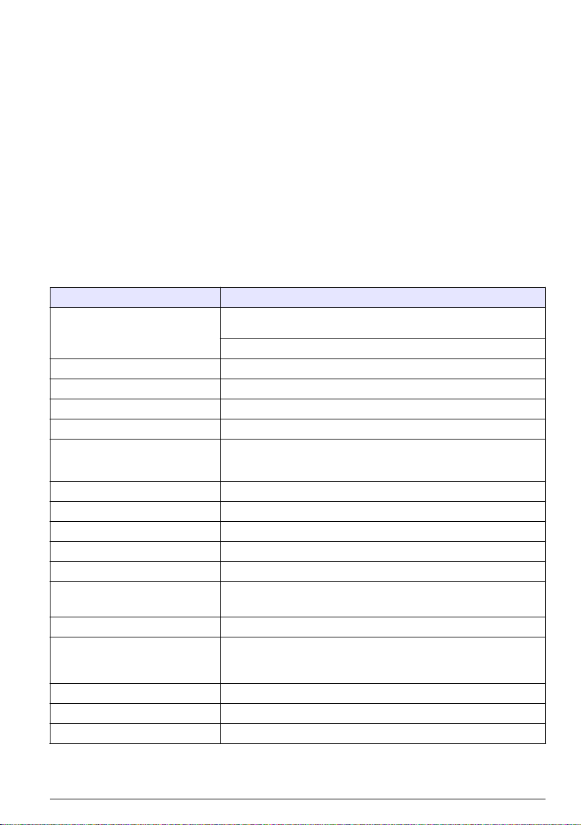
Instrument specifications
Specification Detail
Power requirement Adapter (included in the ship kit): 100–240 VAC, 2.5 A, 50–60 Hz
Instrument: 24 VDC, 75 W maximum
Installation category I
Protection class III
Pollution degree 2
Altitude 2000 m (6562 ft)
Light source Long Life Laser™ diode with 10-year Mean Time To Failure (MTTF), Class 3B Laser,
Pump type Air vacuum, rated for continuous use
Count display Color ¼ VGA TFT touch screen
Interface Windows CE®-based
Maximum count shown 9,999,999
Delay time 00:00:06 to 23:59:59
Sample and hold times Sample: 00:00:01 to 23:59:59
Count alarms 1 to 9,999,999 counts
Data storage 50 to 5000 samples, scrollable on Historical Data review screen
Count cycles Up to 100 while in automatic mode
Locations Up to 999
Exhaust port 3/8-in. NPT thread
810 to 852 nm, 50 mW maximum
Hold: 00:00:00 to 23:59:59
3000 is the default value
English 3
Page 4

Specification Detail
Outputs Ethernet–10Base-T/100Base-TX
RS485 Serial
RS232 Serial
Optional wireless–802.11 b/g compatible
USB Client (Version 1.1)
USB Host (Version 1.1)
Manifold Supports A3432, 32-port manifold system (available on 1 CFM units only)
Enclosure material Stainless steel
Weight without battery 3413 and 3415—7.55 kg (16.6 lb)
3423 and 3425—8.33 kg (18.3 lb)
3445—8.65 kg (19.0 lb)
Size (W x D x H) 31.8 x 25.4 x 20.3 cm (12.5 x 10 x 8 in.)
Environment, operation 0 to 40 °C (32 to 104 °F); 10 to 90% relative humidity, non-condensing
Environment, storage –40 to 50 °C (–40 to 122 °F); 0 to 98% relative humidity, non-condensing
Sample measurement specifications
Sampling
Number of size ranges Standard 6, 8
Particle size ranges and
standard channels
Flow rate Models 3413 and 3415—28.3 L/min (1.00 cfm) ± 5% (Default factory setting)
Zero count Conforms to JIS B9921. 1 count or less in 5 minutes, 95% confidence level
Coincidence loss Models 3413 and 3415—10% at 20,000,000 particles/m3 (566,570 particles/ft3)
Count efficiency Models 3413 and 3423—50% ± 20 % for 0.3 µm, (100% ± 10% at 1.5 times the
Models 3413 and 3423—0.3, 0.5, 1.0, 3.0, 5.0, 10.0 µm
Models 3415 and 3425—0.5, 1.0, 2.0, 3.0, 5.0 and 10.0 or 25.0 µm
Models 3445—0.5, 1.0, 2.0, 3.0, 5.0, 10.0 µm
Models 3423 and 3425—50 L/min (1.77 cfm) ± 5% (Default factory setting)
Model 3445—100 L/min (3.53 cfm) ± 5% (Default factory setting)
Models 3423 and 3425—10% at 10,000,000 particles/m3 (283,280 particles/ft3)
Model 3445—10% at 5,000,000 particles/m3 (141,640 particles/ft3)
minimum sensitivity). Fully complies with ISO21501-4.
Models 3415, 3425 and 3445—50% ± 20% for 0.5 µm, (100% ± 10% at 1.5 times the
minimum sensitivity). Fully complies with ISO21501-4.
Battery specifications
Specification Detail
Battery type Lithium ion smart battery; can be charged, ejected and changed without disruption
Quantity included One (two batteries are provided with the 3445)
4 English
to the system.
Page 5

Specification Detail
Battery life during operation Models 3413 and 3415—6 hours
Models 3423 and 3425—7 hours
Model 3445—3.5 hours
Battery recharge time 6.75 hours minimum, 10 hours maximum
Power 14.4 VDC, 6.6 Ah (2x)
Battery weight 0.66 kg (1.45 lb)
General information
In no event will the manufacturer be liable for direct, indirect, special, incidental or consequential
damages resulting from any defect or omission in this manual. The manufacturer reserves the right to
make changes in this manual and the products it describes at any time, without notice or obligation.
Revised editions are found on the manufacturer’s website.
Safety information
N O T I C E
The manufacturer is not responsible for any damages due to misapplication or misuse of this product including,
without limitation, direct, incidental and consequential damages, and disclaims such damages to the full extent
permitted under applicable law. The user is solely responsible to identify critical application risks and install
appropriate mechanisms to protect processes during a possible equipment malfunction.
Please read this entire manual before unpacking, setting up or operating this equipment. Pay
attention to all danger and caution statements. Failure to do so could result in serious injury to the
operator or damage to the equipment.
Make sure that the protection provided by this equipment is not impaired. Do not use or install this
equipment in any manner other than that specified in this manual.
Use of hazard information
Indicates a potentially or imminently hazardous situation which, if not avoided, will result in death or serious injury.
D A N G E R
W A R N I N G
Indicates a potentially or imminently hazardous situation which, if not avoided, could result in death or serious
injury.
Indicates a potentially hazardous situation that may result in minor or moderate injury.
Indicates a situation which, if not avoided, may cause damage to the instrument. Information that requires special
emphasis.
C A U T I O N
N O T I C E
English 5
Page 6

Precautionary labels
Read all labels and tags attached to the instrument. Personal injury or damage to the instrument
could occur if not observed. A symbol on the instrument is referenced in the manual with a
precautionary statement.
This symbol, if noted on the instrument, references the instruction manual for operation and/or
safety information.
This symbol, when noted on a product enclosure or barrier, indicates that a risk of electrical shock
and/or electrocution exists.
Delicate internal electronic components can be damaged by static electricity, resulting in
degraded performance or eventual failure.
This symbol indicates a laser device is used in the equipment.
This symbol identifies the location of a fuse or current limiting device.
Electrical equipment marked with this symbol may not be disposed of in European public disposal
systems after 12 August of 2005. In conformity with European local and national regulations (EU
Directive 2002/96/EC), European electrical equipment users must now return old or end-of-life
equipment to the Producer for disposal at no charge to the user.
Note: For return for recycling, please contact the equipment producer or supplier for instructions on how to return
end-of-life equipment, producer-supplied electrical accessories, and all auxillary items for proper disposal.
Compliance
This symbol indicates that the instrument is a Class
1 LASER product.
This product complies with IEC/EN 60825-1:2007 and 21 CFR 1040.10 except for deviations
pursuant to Laser Notice No. 50, dated June 24, 2007. FDA accession number: 9020917.
This product is also CE compliant. Contact the manufacturer for complete compliance details.
Country-specific approval for Wi-Fi devices
C A U T I O N
Electromagnetic radiation hazard. Make sure that the antenna is kept at a minimum distance of 20 cm
(7.9 in.) from all personnel in normal use. The antenna cannot be co-located or operated in conjunction
with any other antenna or transmitters.
Products with the wireless option contain a modular RF Wi-Fi device that operates in the 2.4 GHz
range.
• United States FCC ID: R68WIPORTG
• Canada IC ID: 3867A-WIPORTG
Country ISO31662 letter code Country ISO31662 letter code
Austria AT Poland PL
Belgium BA Portugal PT
6 English
Page 7

Country ISO31662 letter code Country ISO31662 letter code
Denmark DK Spain ES
Finland FI Sweden SE
France FR United Kingdom GB
Germany DE Iceland IS
Greece GR Norway NO
Hungary HU Switzerland CH
Ireland IE Turkey TR
Italy IT Netherlands NL
Mexico MX — —
Regulatory RF device approvals
• FCC: Approved as a Modular Device under a TCB Grant of Authorization. FCC ID: R68WIPORTG
• IC: Approved as a Modular Device under Certificat D'Acceptabilite' Technique C-REL ID : 3867AWIPORTG
Opinion: Compliant under the R&TTE Directive 1999/5/EC to the essentials requirements of Article
3.2 according to the assessment procedures in Article 10(5) and Annex IV for (class-2 equipment)
and marked as CE1177.
Certification
The device complies with Part 15 of the FCC Rules and Industry Canada license-exempt RSS
standard(s). Operation is subject to the following conditions:
1. The equipment may not cause harmful interference.
2. The equipment must accept any interference received, including interference that may cause
undesired operation.
Changes or modifications to this wireless communication equipment not expressly approved by the
party responsible for compliance could void the user's authority to operate the equipment. Any
change to the equipment will void the Industry Canada certification and FCC grant.
General product information
This manual describes the use of the MET ONE 3400 Series Particle Counter. The MET ONE
3400 Series Particle Counter counts and measures the size of airborne particles in cleanroom
environments. Refer to Table 1.
Table 1 MET ONE 3400 Series particle counter model numbers
Model number Flow rate Minimum particle size channel (µm)
L/min Ft3/min
3413 28.3 1 0.3
3415 28.3 1 0.5
3423 50 1.77 0.3
3425 50 1.77 0.5
3445 100 3.53 0.5
English 7
Page 8

Installation
W A R N I N G
Multiple hazards. Only qualified personnel must conduct the tasks described in this section of the
document.
Unpack the instrument
Remove all items from the shipping container and inspect for damage. If any items are missing or
damaged, contact the manufacturer. Refer to Figure 1.
Figure 1 MET ONE 3400 components
1 3400 Series Particle Counter 8 Extension tube for isokinetic probe
2 Rechargeable battery (280-120-2024) 9 Zero count filter
3 AC-to-DC power supply (280-300-5000) 10 RS485 connector assembly
4 Power cord (US) 11 USB Flash drive
5 Power cord (EU) 12 Intake cleaning brush
6 Thermal paper rolls for printer (2x) 13 Wireless antenna for Wi-Fi
7 Isokinetic probe 14 Stylus for touchscreen interface
Wiring safety information
W A R N I N G
Electrocution hazard. Make sure that there is easy access to the local power disconnect.
8 English
Page 9

N O T I C E
Always disconnect power to the instrument before electrical connections are made.
Obey all safety statements while connections are made to the instrument.
Electrostatic discharge (ESD) considerations
N O T I C E
Potential Instrument Damage. Delicate internal electronic components can be damaged by static
electricity, resulting in degraded performance or eventual failure.
Refer to the steps in this procedure to prevent ESD damage to the instrument:
• Touch an earth-grounded metal surface such as the chassis of an instrument, a metal conduit or
pipe to discharge static electricity from the body.
• Avoid excessive movement. Transport static-sensitive components in anti-static containers or
packages.
• Wear a wrist strap connected by a wire to earth ground.
• Work in a static-safe area with anti-static floor pads and work bench pads.
Electrical connections
Connect probes, external power, cables and USB devices as shown in Figure 2 and Figure 3.
Figure 2 Back view
1 Exhaust port 4 Manifold controller connector or standard
RS232 port (available on 1 CFM units only)
2 Serial communications RS485 connector 5 Battery ports
3 Auxiliary I/O port for the filter scan probe 6 Supplemental feet
English 9
Page 10

Figure 3 Front and side view
1 Sample intake nozzle 8 USB host connector
2 Touchscreen 9 USB client connector
3 Power button 10 Relative humidity and temperature probe
4 Battery status indicator 11 Air velocity probe connector
5 Ethernet connector 12 Handle
6 Handle 13 Wireless antenna connector
7 Printer 14 Power connector
Note: For best results, use USB flash drives supplied by the manufacturer. Contact Customer Service for additional
support at 800.866.7889 or +1.541.472.6500.
connector
Install the batteries
W A R N I N G
Explosion hazard. To avoid fire and/or explosion, use only the battery type and power supply/charger specified by
the manufacturer. For part numbers, refer to Figure 1 on page 8.
10 English
Page 11

1 2
3 4
English 11
Page 12

Assemble the particle counter system
Figure 4 shows the setup of the particle counter system.
Figure 4 Particle counter assembly
12 English
Page 13

Install the printer paper
To prevent damage to the printer, always operate the particle counter with the recommended thermal
paper installed in the printer. If the particle counter must be used without paper, set the print mode to
"None". To install a roll of thermal printing paper, refer to Figure 5.
Figure 5 Printer paper installation
Particle counter navigation
The functions of the particle counter are accessed from the Counter Navigation screen. Table 2
shows the functions that are accessible through the navigation screen.
Table 2 Screen icon descriptions
Icon Function Description
Sample Measure particle counts. Refer to Measure particle counts on page 14.
Historical Review measurement results in the buffer; print, export or filter data. Refer to the CD for
Export Output file as comma separated value (CSV), tab separated, or PortAll files. Refer to the
information.
CD for information.
English 13
Page 14

Table 2 Screen icon descriptions (continued)
Icon Function Description
Printer Print sample data as hard-copy. Refer to How to use the Print Center on page 15.
Locations Add/edit/remove areas; copy location settings, edit locations settings; edit alarms for
Group Load/add/edit a group; delete a group. Refer to the CD for information.
System Time/Date; Sleep time/backlight timeout; set logon requirements; set sounds for alarms;
Sizes Add/edit/delete a size (optional). Refer to the CD for information.
Test wizard Test and report wizard for ISO, EU-GMP, FS or BS classification compliance. Refer to
Return Return to the previous screen or menu.
specific locations. Refer to the CD for information.
manage users; set the units for flow rates; manage the data buffer. Refer to the CD for
more information. Refer to the CD for information.
the CD for information.
Operation
Log on to the particle counter
Prerequisites
• Start the system.
1. Activate the backlight with a finger or stylus if needed.
2. Push the LOCK icon to log out a previous user. Push LOCK again to see the logon screen.
3. Enter the user name and password. Confirm.
Note: Push the ALT key to access special characters.
Measure particle counts
After a complete particle count measurement, the number of particles measured will show on the
screen and be stored as data. Other configured parameters, such as relative humidity, temperature
and air velocity will be shown and stored in data.
1. Remove the protective cap from the inlet tube on the counter.
2. On the Counter Navigation screen, push SAMPLE.
3. To start the particle count, push the RUN button. The RUN button will change to a STOP button
while the count is measured.
Note: Push STOP to end the test before the count is complete. Incomplete particle count data will not be stored
or printed.
4. When the count measurement is complete, the test will stop automatically.
14
English
Page 15

Change the particle count location
There are two methods to change the location for a particle count.
• On the Sample screen, push the location name. Select the new location name and confirm.
• On the Sample screen, push the PLUS button to increment the location, or push the MINUS button
to decrement the location.
See settings during the particle count
Location and group settings can be seen at any time during the particle count cycle.
• On the Sample screen, select the Settings tab on the right side of the screen.
See historical data during the particle count
Historical sample data can be seen at any time during the particle count cycle.
1. On the Sample screen, select the ARROW button.
2. Select the HISTORICAL DATA icon to see the data.
Use the filter scan probe
N O T I C E
The filter scan probe function applies to 1 CFM and 50 LPM units only.
1. On the Counter Navigation screen, push SAMPLE.
2. In the Test screen, push the FILTER icon.
3. To start the test, push START FILTER PROBE TEST.
4. To end the test, push STOP FILTER PROBE TEST.
5. Push PRINTER to generate a brief report of the last completed test.
How to use the Print Center
About the Print Center
N O T I C E
To avoid damage to the printer, do not operate the printer without paper. If the particle counter must be used
without paper, be sure to set the print mode to "None".
The particle counter has a built-in printer. The Print Center screen is accessible from the:
• Counter Navigation screen
• Historical screen
• System Diagnostics screen
• Test/Report Wizard screen
• Area/Location Setup screen
On the Print Center screen the user can:
• Set automatic print functions
• Print buffer records or count averages
Note: Filtered data is printed from the Historical screen.
Print records manually
The buffer holds 5000 records maximum. The Print Center can print the entire buffer or the average
of count cycles. To print records manually:
English
15
Page 16

1. On the counter Navigation screen, push PRINTER.
2. On the Print Center screen, select the print option for the data.
3. The data will begin to print.
• To cancel the print job, push CANCEL PRINT.
• To return to Counter Navigation, push RETURN.
Set automatic print functions
Note: If the sample period is very brief and the hold time is zero, some sample data may be skipped.
1. On the Counter Navigation screen, push PRINTER.
2. On the Print Center screen, select the Sample Print Mode field. Select an option for automatic
printing.
Option Description
None No data will print automatically
Alarms Prints results when a count alarm is exceeded
Cycles Prints the results of the first count cycle and multiples of the programmed count cycle
All Prints results after each count cycle is finished
3. Push ENTER to confirm.
Maintenance
W A R N I N G
Multiple hazards. Do not disassemble the instrument for maintenance or service. If the internal components must
be cleaned or repaired, contact the manufacturer.
Personal injury hazard. Only qualified personnel should conduct the tasks described in this section of the manual.
C A U T I O N
Clean the instrument exterior
The instrument exterior can be cleaned as needed. To avoid human exposure to potentially
dangerous chemicals, make sure to clean the touchscreen immediately after contact with chemicals.
N O T I C E
Do not leave visible moisture on the instrument or touchscreen. Moisture can penetrate the touchscreen and
damage electronics inside.
1. Put the cap on the sample air intake nozzle.
2. Spray a mild cleaning solution on a soft cloth. Wipe the outside of the instrument carefully.
3. Use a soft, dry cloth to wipe the touchscreen surface. If needed, moisten the soft cloth with a mild
cleaning solution.
Set the count to zero
Do this procedure after unexpectedly high particle counts. This procedure will verify that the particle
counter works correctly and will remove residual particles.
1. Put the zero-count filter on the intake tube. Refer to Figure 1 on page 8.
2. Turn on the unit and log in if needed.
3. Push SAMPLE.
16
English
Page 17

4. Push RUN.
5. Repeat the process until the particle counts return to zero.
Charge the batteries in the particle counter
Batteries in the 3400 will begin to charge when the AC power cord is connected. A complete charge
in the instrument takes approximately 10 hours. The battery is considered to be fully charged when
they display shows the charge between 95% and 100%.
Prerequisite: Install the batteries in the instrument. Refer to Install the batteries on page 10.
N O T I C E
Discard the used batteries according to local regulations or contact the manufacturer. Do not put exhausted
batteries in the domestic waste.
1. Attach the power supply to the unit. Refer to Figure 3 on page 10.
2. Connect the unit power supply to the external power through the AC power adapter.
The battery status light will show the level of power in the battery. Refer to Table 3.
Table 3 Battery LED color indications
LED state LED color Battery status Charge status
Flashing Orange Low power Not charging
Flashing Green Low power Charging
Solid Green Charged Charging
Diagnostics and Troubleshooting
The Diagnostics screen shows information that may be needed for troubleshooting. Table 4 shows
an example of a failure notification on the Diagnostics screen.
Table 4 System Diagnostics screen example - Clock battery failure
Signal Value Status
Calibration 0.00 VDC OFF
Flow 0.00 VDC OFF
Clock battery 0.00 VDC FAIL
Battery 1 (bottom) 16.42 VDC PASS
Battery 2 (top) 16.44 VDC PASS
Laser current N/A – –
For troubleshooting that involves technical support from the manufacturer, the user may need to fax
a system status printout to technical support.
1. On the Counter Navigation screen, push DIAGNOSTICS.
2. Go to the Counter tab to see information about the system, such as serial number, model and
calibration date.
3. Go to the Calibration tab to see current calibration information.
4. On the Diagnostics screen, push PRINT.
The printout will show the serial number, date and time and other data about the system.
English
17
Page 18

Table des matières
Caractéristiques à la page 18 Fonctionnement à la page 30
Généralités à la page 20 Maintenance à la page 32
Installation à la page 23 Diagnostics et dépannage à la page 33
Navigation du compteur de particules à la page 29
Informations supplémentaires
Des informations supplémentaires sont disponibles sur le site Web du fabricant.
Caractéristiques
Les caractéristiques techniques peuvent être modifiées sans préavis.
Spécifications de l'appareil
Caractéristique Détails
Exigences électriques Adaptateur (inclus dans le kit d'expédition 100–240 V ca, 2,5 A, 50–60 Hz
Appareil : 24 VCC, 75 W maximum
Catégorie d’installation I
Classe de protection III
Niveau de pollution 2
Altitude 2 000 m (6 562 ft)
Source lumineuse Diode Long Life Laser™ avec un temps moyen de fonctionnement avant
Type de pompe A vide d'air, classé pour une utilisation continue
Affichage du comptage Écran tactile couleur ¼ VGA TFT
Interface Basé sur Windows CE
Comptage maximum affiché 9,999,999
Temps de retard 00:00:06 à 23:59:59
Temps d'échantillonnage et de pause Échantillonnage : 00:00:01 à 23:59:59
Alarmes de comptage 1 à 9 999 999 comptages
Stockage des données 50 à 5 000 échantillons, défilement sur l'écran d'aperçu des Données
Cycles de comptage Jusqu'à 100 en mode automatique
Emplacements Jusqu'à 999
Port d'évacuation 3/8-in. Filetage NPT
défaillance (MTTF) de 10 ans, laser de classe 3B, 810 à 852 nm, 50 mW
maximum
®
Pause : 00:00:00 à 23:59:59
historiques
La valeur par défaut est 3 000
18 Français
Page 19

Caractéristique Détails
Sorties Ethernet–10Base-T/100Base-TX
Série RS485
Série RS232
Sans fil en option–802.11b/g compatible
Client USB (Version 1.1)
USB Hôte (Version 1.1)
Collecteur Supports A3432, système de collecteur 32 ports (disponible sur des
Matériau du boîtier Acier inoxydable
Poids sans batterie 3413 et 3415—7,55 kg
Taille (l x P x H) 31,8 x 25,4 x 20,3 cm (12,5 x 10 x 8 pouces)
Environnement, fonctionnement 0° à 40°C (32 à 104°F) ; 10 à 90 % d'humidité relative sans condensation
Environnement, stockage –40° à 50°C (–40 à 122°F) ; 0 à 98 % d'humidité relative sans
unités 1 CFM uniquement)
3423 et 3425—8,33 kg
3445—8,65 kg
condensation
Spécifications de mesure de l'échantillon
Échantillonnage
Nombre de gammes de
taille
Gammes de taille des
particules et canaux
standards
Débit Modèles 3413 et 3415—28,3 l/min (1,00 cfm) ± 5 % (réglage d'usine par défaut)
Comptage à zéro Conforme à JIS B9921. 1 comptage ou moins en 5 minutes, niveau de fiabilité à
Erreur de coïncidences Modèles 3413 et 3415—10 % à 20 000 000 particules/m3 (566 570 particules/ft3)
Efficacité du comptage Modèles 3413 et 3423—50 % ± 20 % pour 0,3 µm, (100 % ± 10 % à 1,5 fois la
Standard 6, 8
Modèles 3413 et 3423—0,3, 0,5, 1,0, 3,0, 5,0, 10,0 µm
Modèles 3415 et 3425—0,5, 1,0, 2,0, 3,0, 5,0 et 10,0 ou 25,0 µm
Modèles 3445—0,5, 1,0, 2,0, 3,0, 5,0, 10,0 µm
Modèles 3423 et 3425—50 l/min (1,77 cfm) ± 5 % (réglage d'usine par défaut)
Modèles 3445—100 l/min (3,53 cfm) ± 5% (réglage d'usine par défaut)
95%
Modèles 3423 et 3425—10 % à 10 000 000 particules/m3 (283 280 particules/ft3)
Modèle 3445—10 % à 5 000 000 particules/m3 (141 640 particules/ft3)
sensibilité minimum). Totalement conforme à la norme ISO21501-4.
Modèles 3415 et 3425—50 % ± 20 % pour 0,5 µm, (100 % ± 10 % à 1,5 fois la
sensibilité minimum). Totalement conforme à la norme ISO21501-4.
Français 19
Page 20

Spécification des batteries
Caractéristique Détails
Type de batterie Batterie intelligente au lithium-ion : peut être chargée, éjectée et
Quantité incluse Une (le 3445 est fourni avec deux batteries)
Durée de vie de la batterie en fonctionnement Modèles 3413 et 3415—6 heures
Temps de recharge de la batterie 6,75 heures minimum, 10 heures maximum
Alimentation 14,4 V cc, 6,6 Ah (2x)
Poids de la batterie 0,66 kg (1,45 lb)
remplacée sans interrompre le système.
Modèles 3423 et 3425—7 heures
Modèle 3445—3,5 heures
Généralités
En aucun cas le constructeur ne saurait être responsable des dommages directs, indirects, spéciaux,
accessoires ou consécutifs résultant d'un défaut ou d'une omission dans ce manuel. Le constructeur
se réserve le droit d'apporter des modifications à ce manuel et aux produits décrits à tout moment,
sans avertissement ni obligation. Les éditions révisées se trouvent sur le site Internet du fabricant.
Consignes de sécurité
A V I S
Le fabricant décline toute responsabilité quant aux dégâts liés à une application ou un usage inappropriés de ce
produit, y compris, sans toutefois s'y limiter, des dommages directs ou indirects, ainsi que des dommages
consécutifs, et rejette toute responsabilité quant à ces dommages dans la mesure où la loi applicable le permet.
L'utilisateur est seul responsable de la vérification des risques d'application critiques et de la mise en place de
mécanismes de protection des processus en cas de défaillance de l'équipement.
Veuillez lire l'ensemble du manuel avant le déballage, la configuration ou la mise en fonctionnement
de cet appareil. Respectez toutes les déclarations de prudence et d'attention. Le non-respect de
cette procédure peut conduire à des blessures graves de l'opérateur ou à des dégâts sur le matériel.
Assurez-vous que la protection fournie avec cet appareil n'est pas défaillante. N'utilisez ni n'installez
cet appareil d'une façon différente de celle décrite dans ce manuel.
Interprétation des indications de risques
Indique une situation de danger potentiel ou imminent qui, si elle n'est pas évitée, entraîne des blessures graves,
voire mortelles.
D A N G E R
A V E R T I S S E M E N T
Indique une situation de danger potentiel ou imminent qui, si elle n'est pas évitée, peut entraîner des blessures
graves, voire mortelles.
Indique une situation de danger potentiel qui peut entraîner des blessures mineures ou légères.
Indique une situation qui, si elle n'est pas évitée, peut occasionner l'endommagement du matériel. Informations
nécessitant une attention particulière.
A T T E N T I O N
A V I S
20 Français
Page 21

Étiquettes de mise en garde
Lisez toutes les informations et toutes les étiquettes apposées sur l’appareil. Des personnes peuvent
se blesser et le matériel peut être endommagé si ces instructions ne sont pas respectées. Un
symbole sur l'appareil est désigné dans le manuel avec une instruction de mise en garde.
Si l'appareil comporte ce symbole, reportez-vous au manuel d'utilisation pour consulter les
informations de fonctionnement et de sécurité.
S'il se trouve sur l’emballage d'un produit ou une barrière, ce symbole indique la présence d’un
danger de choc électrique et/ou d’électrocution.
Les composants électroniques internes de l'appareil peuvent être endommagés par l'électricité
statique, qui risque d'altérer ses performances et son fonctionnement.
Ce symbole indique qu'un dispositif laser est utilisé dans l'équipement.
Ce symbole indique l’emplacement d’un fusible ou de tout dispositif de protection contre les
surintensités de courant.
En Europe, depuis le 12 août 2005, les appareils électriques comportant ce symbole ne doivent
pas être jetés avec les autres déchets. Conformément à la réglementation nationale et
européenne (Directive 2002/96/CE), les appareils électriques doivent désormais être, à la fin de
leur service, renvoyés par les utilisateurs au fabricant, qui se chargera de les éliminer à ses frais.
Remarque : Pour le retour à des fins de recyclage, veuillez contactez le fabricant ou le fournisseur d'équipement
afin d'obtenir les instructions sur la façon de renvoyer l'équipement usé, les accessoires électriques fournis par le
fabricant, et tous les articles auxiliaires pour une mise au rebut appropriée.
Conformité
Ce symbole indique que l'appareil est un produit LASER
de classe 1.
Ce produit est conforme aux normes IEC/EN 60825-1:2007 et 21 CFR 1040.10, à l'exception des
différences faisant suite à la notice Laser n° 50 datée du 24 juin 2007. Numéro d'accession FDA :
9020917.
Ce produit est également certifié conforme CE. Contactez le fabricant pour avoir tous les détails sur
la conformité.
Agrément spécifique par pays pour les dispositifs Wi-Fi
A T T E N T I O N
Risque lié au rayonnement électromagnétique. Assurez-vous que l'antenne se trouve à une distance
minimum de 20 cm (7,9 pouces) de l'ensemble du personnel dans des conditions d'utilisation dites
normales. L'antenne ne peut pas être colocalisée ou utilisée en combinaison avec une autre antenne ou
d'autres transmetteurs.
Les produits avec l'option sans fil contiennent un dispositif Wi-Fi modulaire RF fonctionnant dans une
gamme de 2,4 GHz.
• Etats-Unis FCC ID : R68WIPORTG
Français
21
Page 22

• Canada IC ID : 3867A-WIPORT
Pays Code à lettres ISO 31662 Pays Code à lettres ISO 31662
Autriche AT Pologne PL
Belgique BA Portugal PT
Danemark DK Espagne ES
Finlande FI Suède SE
France FR Royaume Uni GB
Allemagne DE Islande IS
Grèce GR Norvège NO
Hongrie HU Suisse CH
Irlande IE Turquie TR
Italie IT Pays-Bas NL
Mexique MX — —
Agréments des dispositifs de contrôle RF
• FCC : Approuvé comme dispositif modulaire l'accord de droit TCB. FCC ID : R68WIPORTG
• IC: Approuvé comme dispositif modulaire sous le Certificat D'Acceptabilité' TechniqueC-REL ID:
3867A-WIPORT
Opinion : Conforme à la directive R&TTE 1999/5/EC sur les exigences essentielles de l' Article
3.2 conformément aux procédures de l' Article 10(5) et Annexe IV for (class-2 équipement) et indiqué
comme CE1177.
Certification
Le produit répond aux exigences de la section 15 de la réglementation FCC et aux normes RSS
d'Industrie Canada. Le fonctionnement est soumis aux conditions suivantes :
1. Cet équipement ne peut pas causer d'interférence nuisible.
2. Cet équipement doit accepter toutes les interférences reçues, y compris celles qui pourraient
entraîner un fonctionnement inattendu.
Les modifications de cet équipement de communication sans fil qui n’ont pas été expressément
approuvées par le responsable de la conformité aux limites pourraient annuler l’autorité dont
l’utilisateur dispose pour utiliser cet équipement. Tout changement apporté à l'équipement annulera
la certification d'Industrie Canada et l'autorisation FCC.
Informations générales sur le produit
Ce manuel décrit l'utilisation des Compteurs de particules MET ONE Série 3400. Le Compteur de
particules MET ONE Série 3400 compte et mesure la dimension des particules en suspension dans
les environnements de salle blanche. Voir Tableau 1.
Tableau 1 Références du compteur de particules MET ONE série 3400
N° de modèle Débit Canal de taille de particule minimum (µm)
l/min Ft3/min
3413 28,3 1 0,3
3415 28,3 1 0,5
3423 50 1,77 0,3
22 Français
Page 23

Tableau 1 Références du compteur de particules MET ONE série 3400 (suite)
N° de modèle Débit Canal de taille de particule minimum (µm)
l/min Ft3/min
3425 50 1,77 0,5
3445 100 3,53 0,5
Installation
A V E R T I S S E M E N T
Dangers multiples. Seul le personnel qualifié doit effectuer les tâches détaillées dans cette section du
document.
Déballage de l'appareil
Retirez tous les éléments de la boîte d'emballage et inspectez-les à la recherche de dommages. Si
un des éléments est endommagé ou manquant, contactez le fabricant. Voir Figure 1.
Français 23
Page 24

Figure 1 Composants du MET ONE 3400
1 Compteur de particules séries 3400 8 Tube rallonge pour capteur isocinétique
2 Batterie rechargeable (280-120-2024) 9 Filtre de comptage à zéro
3 Alimentation CA vers CC (280-300-5000) 10 Ensemble connecteur RS485
4 Cordon d'alimentation (américain) 11 Clé mémoire USB
5 Cordon d'alimentation (UE) 12 Brosse de nettoyage de l'aspiration
6 Rouleaux de papier thermique pour l'imprimante
(2x)
7 Capteur isocinétique 14 Stylet pour interface à écran tactile
13 Antenne sans fil pour Wifi
Information de sécurité du câblage
A V E R T I S S E M E N T
Risque d'électrocution Assurez-vous de disposer d'un accès facile à la coupure d'alimentation locale.
Toujours débrancher l'appareil de l'alimentation avant d'effectuer tout branchement électrique.
Respectez toutes les mesures de sécurité pendant que l'appareil est branché.
Remarques relatives aux décharges électrostatiques
Dégât potentiel sur l'appareil Les composants électroniques internes de l'appareil peuvent être
endommagés par l'électricité statique, qui risque d'altérer ses performances et son fonctionnement.
24 Français
A V I S
A V I S
Page 25

Reportez-vous aux étapes décrites dans cette procédure pour éviter d'endommager l'appareil par
des décharges électrostatiques.
• Touchez une surface métallique reliée à la terre (par exemple, le châssis d'un appareil, un conduit
ou un tuyau métallique) pour décharger l'électricité statique de votre corps.
• Evitez tout mouvement excessif. Transportez les composants sensibles à l'électricité statique dans
des conteneurs ou des emballages antistatiques.
• Portez un bracelet spécial relié à la terre par un fil.
• Travaillez dans une zone à protection antistatique avec des tapis de sol et des sous-mains
antistatiques.
Branchements électriques
Branchez les capteurs, l'alimentation électrique externe, les câbles et les dispositifs USB tel
qu'indiqué au Figure 2 et Figure 3.
Figure 2 Vue arrière
1 Port d'évacuation 4 Connecteur pour contrôleur Manifold ou port
2 Connecteur RS485 de communication série 5 Logements pour batterie
3 Port E/S auxiliaire pour la sonde de balayage du
filtre
standard RS232 (disponible seulement sur les
appareils 1 CFM)
6 Pied supplémentaire
Français 25
Page 26

Figure 3 Vue avant et vue latérale
1 Buse d'aspiration d'échantillonnage 8 Connecteur hôte USB
2 Ecran tactile 9 Connecteur client USB
3 Bouton d'alimentation 10 Connecteur de sonde d'humidité relative et de
4 Indicateur d'état de la batterie 11 Connecteur de sonde de vitesse de l'air
5 Connecteur Ethernet 12 Poignée
6 Poignée 13 Connecteur d'antenne sans fil
7 Imprimante 14 Connecteur d'alimentation
Remarque : Pour obtenir de meilleurs résultats, utilisez les clés mémoire USB fournies par le fabricant. Pour toute
assistance complémentaire, contactez le service client au 800.866.7889 ou +1.541.472.6500.
température
Installation des piles
A V E R T I S S E M E N T
Risque d'explosion. Afin d'éviter tout risque d'incendie/explosion, utilisez le type de batterie et
d'alimentation/chargeur spécifiés par le fabricant. Pour les références, reportez-vous à Figure 1 à la page 24.
26 Français
Page 27

1 2
3 4
Français 27
Page 28

Assemblage du système de compteur de particules
Figure 4 illustre le réglage du système de compteur de particules.
Figure 4 Assemblage du compteur de particules
28 Français
Page 29

Installer le papier d'impression
Afin d'éviter d'endommager l'imprimante, utilisez toujours le compteur de particules avec le papier
thermique recommandé et installé dans l'imprimante. Si le compteur de particules doit être utilisé
sans papier, assurez-vous de régler le Mode d'impression sur "Aucun". Pour installer un rouleau de
papier d'impression thermique, reportez-vous à Figure 5.
Figure 5 Installation du papier d'impression
Navigation du compteur de particules
Les fonctions du compteur de particules sont accessibles depuis l'écran Navigation du compteur.
Tableau 2 affiche les fonctions accessibles via l'écran de navigation.
Tableau 2 Descriptions des icônes de l'écran
Icône Fonction Description
Echantillon Mesurer le comptage de particules. Reportez-vous à Mesure de comptage des
Historique Consulter les résultats de mesure dans la mémoire tampon : imprimer, exporter ou
Exporter Fichiers de sortie de valeurs séparées par des virgules (CSV), séparés par des
particules à la page 30.
filtrer les données. Consultez le CD pour plus d'informations.
onglets ou fichier PortAll. Consultez le CD pour plus d'informations.
Français 29
Page 30

Tableau 2 Descriptions des icônes de l'écran (suite)
Icône Fonction Description
Imprimante Imprimer les données d'échantillon sur papier. Voir Comment utiliser le Print Center
à la page 31.
Emplacements Ajouter/modifier/retirer des zones, copier les réglages d'emplacement, éditer les
Groupe Charger/ajouter/éditer un groupe, supprimer un groupe. Consultez le CD pour plus
Système Heure/date, temps de veille/temporisation rétro-éclairage, définir les conditions de
Tailles Ajouter/éditer/supprimer une taille (en option). Consultez le CD pour plus
Assistant de test Assistant de test et de rapport pour conformité de classification ISO, EU-GMP, FS
Retour Retour à l'écran ou menu précédent.
réglages d'emplacement, éditer les alarmes pour les emplacements spécifiques.
Consultez le CD pour plus d'informations.
d'informations.
connexion, définir les sons pour les alarmes, gérer les utilisateurs, régler les
appareils pour le débit, gérer les données tampon. Consultez le CD pour plus
d'informations. Consultez le CD pour plus d'informations.
d'informations.
ou BS. Consultez le CD pour plus d'informations.
Fonctionnement
Connexion au compteur de particules
Actions préalables nécessaires
• Démarrez le système.
1. Activez le rétro-éclairage avec un doigt ou le stylet si nécessaire.
2. Appuyez sur l'icône VERROU pour déconnecter l'utilisateur précédent. Appuyez de nouveau sur
l'icône VERROU pour afficher l'écran de connexion.
3. Saisissez le nom d'utilisateur et le mot de passe. Validez.
Remarque : Appuyez sur la touche ALT pour accéder aux caractères spéciaux.
Mesure de comptage des particules
Après une mesure de comptage complet des particules, le nombre de particules mesurées s'affiche
à l'écran et est enregistré dans les données. D'autres paramètres configurés (par exemple, l'humidité
relative, la température et la vitesse de l'air) s'affichent et sont enregistrés dans les données.
1. Retirez le capuchon de protection du tube d'entrée du compteur.
2. Sur l'écran de Navigation du compteur, appuyez sur ECHANTILLON.
30
Français
Page 31

3. Pour démarrer le comptage de particules, appuyez sur la touche EXECUTION. La touche
EXECUTION devient la touche ARRET lorsque le comptage est en cours.
Remarque : Appuyez sur ARRET pour arrêter le test avant la fin du comptage. Des données de comptage de
particules incomplètes ne seront pas enregistrées ni imprimées.
4. Lorsque la mesure de comptage est terminée, le test s'arrête automatiquement.
Changement d'emplacement du compteur de particules
Il existe deux méthodes pour changer l'emplacement d'un compteur de particules.
• Sur l'écran Echantillon, appuyez sur le nom d'emplacement. Sélectionnez le nom du nouvel
emplacement et confirmez.
• Sur l'écran Echantillon, appuyez sur la touche PLUS pour augmenter l'emplacement ou appuyez
sur la touche MOINSpour réduire l'emplacement.
Consultation des réglages pendant le comptage de particules
Les réglages d'emplacement et de groupe peuvent être visualisés à tout moment pendant le cycle de
comptage de particules.
• Sur l'écran Echantillon, sélectionnez l'onglet Réglages sur le côté droit de l'écran.
Consultation des données d'historique pendant le comptage de particules
Les données d'échantillon historique peuvent être visualisées à tout moment pendant le cycle de
comptage de particules.
1. Sur l'écran Echantillon, sélectionnez la touche FLECHE.
2. Sélectionnez l'icône DONNEES HISTORIQUES pour afficher les données.
Utilisation de la sonde de balayage du filtre
A V I S
La fonctionnalité de la sonde de balayage du filtre n'est applicable qu'aux appareils 1 CFM et 50 LPM.
1. Sur l'écran de Navigation du compteur, appuyez sur ECHANTILLON.
2. Sur l'écran Test, appuyez sur l'icône FILTRE.
3. Pour lancer le test, appuyez sur DEMARRER LE TEST DE LA SONDE DE FILTRE.
4. Pour arrêter le test, appuyez sur ARRETER LE TEST DE LA SONDE DE FILTRE.
5. Appuyez sur IMPRIMANTE pour créer un bref rapport du dernier test terminé.
Comment utiliser le Print Center
A propos de Print Center
A V I S
Afin d'éviter d'endommager l'imprimante, n'utilisez pas cette dernière sans papier. Si le compteur de particules
doit être utilisé sans papier, assurez-vous de régler le Mode d'impression sur "Aucun".
Le compteur de particules est équipé d'une imprimante intégrée. L'écran Print Center est accessible
depuis :
• L'écran Navigation du compteur
• L'écran Historique
• L'écran Diagnostics du système
• L'écran Assistant de Test/Rapport
• L'écran Réglage Zone/Emplacement
Sur l'écran Print Center, l'utilisateur peut :
• Régler des fonctions d'impression automatique
Français
31
Page 32

• Imprimer des dossiers en mémoire tampon ou des moyennes de comptage
Remarque : Les données filtrées sont imprimées à partir de l'écran Historique.
Impression manuelle des relevés
La mémoire tampon conserve 5 000 relevés maximum. Le Print Center peut imprimer l'ensemble de
la mémoire tampon ou la moyenne des cycles de comptage. Pour imprimer les relevés
manuellement :
1. Sur l'écran Navigation du compteur, appuyez sur IMPRIMANTE.
2. Sur l'écran Print Center, sélectionnez l'option d'impression pour les données.
3. Les données commencent à être imprimées.
• Pour annuler la tâche d'impression, appuyez sur ANNULER L'IMPRESSION.
• Pour revenir à l'écran Navigation du compteur, appuyez sur RETOUR.
Réglage des fonctions d'impression automatique
Remarque : Si la période d'échantillonnage est très courte et que le temps de pause est de 0, certaines données
d'échantillon ne sont pas nécessaires.
1. Sur l'écran Navigation du compteur, appuyez sur IMPRIMANTE.
2. Sur l'écran Print Center, sélectionnez le champ Mode d'impression de l'échantillon. Sélectionnez
une option pour l'impression automatique.
Option Description
None (Aucun) Aucune donnée ne sera imprimée automatiquement
Alarmes Imprime les résultats lorsque l'alarme de comptage est dépassée
Cycles Imprime les résultats du premier cycle de comptage et les multiples du cycle de comptage
Tous Imprime les résultats à la fin de chaque cycle de comptage
3. Appuyez sur ENTREE pour confirmer.
programmé.
Maintenance
A V E R T I S S E M E N T
Dangers multiples. Ne démontez pas l'appareil pour l'entretien. Si les composants internes doivent être nettoyés
ou réparés, contactez le fabricant.
Risque de blessures corporelles Seul le personnel qualifié est autorisé à entreprendre les opérations décrites
dans cette section du manuel.
Nettoyage de l'extérieur de l'appareil
L'extérieur de l'appareil peut être nettoyé si nécessaire. Afin d'éviter une exposition humaine à des
produits chimiques potentiellement dangereux, veuillez nettoyer l'écran tactile immédiatement après
le contact avec des produits chimiques.
32
Français
A T T E N T I O N
Page 33

A V I S
Ne laissez pas de trace d'humidité sur l'appareil ou sur l'écran. L'humidité peut pénétrer à l'intérieur de l'écran
tactile et endommager les circuits électroniques à l'intérieur.
1. Placez le capuchon sur la buse d'aspiration d'échantillonnage.
2. Vaporisez une solution nettoyante douce sur un chiffon doux. Essuyez soigneusement l'extérieur
de l'appareil..
3. Utilisez un chiffon doux et sec pour essuyer l'écran tactile. Le cas échéant, humidifiez le chiffon
doux avec une solution de détergent doux.
Réglage du comptage à zéro
Appliquez cette procédure à la suite d'un comptage de particules anormalement élevé. Cette
procédure permet de vérifier que le comptage de particules fonctionne correctement et d'éliminer les
particules résiduelles.
1. Placez le filtre de comptage à zéro sur le tube d'admission. Voir Figure 1 à la page 24.
2. Allumez l'appareil et connectez-vous si nécessaire.
3. Appuyez sur ÉCHANTILLON.
4. Appuyez surEXECUTION.
5. Répétez la procédure jusqu'à ce que le comptage de particules revienne à zéro.
Charge des batteries dans le compteur de particules
Sur le modèle 3400, les batteries commencent à charger lorsque le cordon d'alimentation secteur est
branché. La charge complète de l'appareil prend environ 10 heures. On considère que la batterie est
entièrement chargée lorsque l'écran affiche un niveau de charge compris entre 95 % et 100 %.
Actions préalables nécessaires :installez les batteries dans l'appareil. Voir Installation des piles
à la page 26.
A V I S
Éliminez les batteries usagées conformément aux réglementations locales ou contactez le fabricant. Ne jetez pas
les batteries usagées avec les ordures ménagères.
1. Branchez l'alimentation à l'unité. Voir Figure 3 à la page 26.
2. Branchez l'alimentation de l'unité à l'alimentation externe par l'adaptateur d'alimentation secteur.
Le voyant d'état de la batterie indique le niveau de puissance de la batterie. Voir Tableau 3.
Tableau 3 Indications des couleurs de la LED de la batterie
Etat de la LED Couleur du voyant Etat des batteries Etat de charge
Clignotant Orange Puissance faible Pas en charge
Clignotant Vert Puissance faible Chargement
Fixe Vert Chargé Chargement
Diagnostics et dépannage
L'écran Diagnostics affiche les informations potentiellement nécessaires au dépannage. Tableau 4
présente un exemple de notification de défaillance dans l'écran Diagnostics.
Tableau 4 Exemple d'écran Diagnostics du système - Défaillance de la batterie d'horloge
Signal Valeur Statut
Etalonnage 0,00 V CC DESACTIVE
Débit 0,00 V CC DESACTIVE
Français 33
Page 34

Tableau 4 Exemple d'écran Diagnostics du système - Défaillance de la batterie d'horloge
(suite)
Signal Valeur Statut
Batterie horloge 0,00 V CC ECHEC
Batterie 1 (bas) 16,42 V CC SUCCES
Batterie 2 (haut) 16,44 V CC SUCCES
Courant laser N/A – –
Pour le dépannage qui nécessite une assistance technique de la part du fabricant, l'utilisateur peut
avoir besoin de faxer une copie de l'état du système au support technique.
1. Sur l'écran Navigation du compteur, appuyez sur DIAGNOSTICS.
2. Ouvrez l'onglet COMPTEUR pour consulter les informations relatives au système, telles que le
numéro de série, le modèle et la date d'étalonnage.
3. Ouvrez l'onglet Etalonnage pour consulter les informations d'étalonnage actuelles.
4. Sur l'écran Diagnostics, appuyez sur IMPRIMER.
L'impression doit indiquer le numéro de série, la date et l'heure ainsi que d'autres informations
relatives au système.
34 Français
Page 35
Contenido
Especificaciones en la página 35 Funcionamiento en la página 47
Información general en la página 37 Mantenimiento en la página 49
Instalación en la página 40 Diagnóstico y solución de problemas en la página 50
Navegación del contador de partículas
en la página 46
Información adicional
En el sitio web del fabricante encontrará información adicional.
Especificaciones
Las especificaciones están sujetas a cambios sin previo aviso.
Especificaciones del instrumento
Especificación Detalles
Requisitos de energía Adaptador (incluido en el paquete de envío): 100–240 VAC, 2.5 A,
Categoría de instalación I
Clase de protección III
Grado de contaminación 2
Altitud 2000 m (6562 pies)
Fuente de luz Diodo láser™ de larga duración con un Tiempo medio de fallo (Mean
Tipo de bomba Vacío del aire, para uso continuo
Pantalla de recuento Pantalla táctil VGA TFT ¼ color
Interfaz Basada en Windows CE
Cuenta máxima mostrada 9.999.999
Tiempo de retardo 00:00:06 a 23:59:59
Tiempos de muestra y espera Muestra: 00:00:01 a 23:59:59
Alarmas de cuenta 1 a 9.999.999 cuentas
Almacenamiento de datos De 50 a 5000 muestras, desplegables en pantalla de revisión de datos
Ciclos de recuento Hasta 100 en modo automático
Ubicaciones Hasta 999
Puerto de escape 3/8-pulg. Rosca NPT
50–60 Hz
Instrumento: 24 VCC, 75 W como máximo
Time To Failure - MTTF) de 10 años, láser clase 3B, 810 a 852 nm,
50 mW máximo
®
Espera: 00:00:00 to 23:59:59
históricos
3000 es el valor predeterminado
Español 35
Page 36

Especificación Detalles
Salidas Ethernet–10Base-T/100Base-TX
RS485 Serie
RS232 Serie
Inalámbrico opcional–802.11 b/g compatible
Cliente USB (Versión 1.1)
Puerto host USB (Versión 1.1)
Distribuidor Admite el sistema de colector de 32 puertos A3432 (disponible
Material de la caja Acero inoxidable
Peso sin batería 3413 y 3415—7,55 kg (16,6 lb)
Tamaño (Ancho x Profundidad x Alto) 31.8 x 25.4 x 20.3 cm (12.5 x 10 x 8 pulg.)
Entorno, funcionamiento 0° a 40 °C (32° a 104 °F); 10 a 90% de humedad relativa, sin
Entorno, almacenamiento –40° a 50 °C (– 40° a 122 °F); 0 a 98% de humedad relativa, sin
únicamente en unidades con un pie cúbico/min)
3423 y 3425—8,33 kg (18,3 lb)
3445—8,65 kg (19,0 lb)
condensación
condensación
Especificaciones de medición de muestras
Muestra
Número de rangos de
tamaño
Canales estándar y
rangos de tamaño de
las partículas
Caudal Modelos 3413 y 3415—28,3 L/min (1,00 cfm) ± 5% (Configuración predeterminada de
Cuenta cero Conforme con JIS B9921. 1 cuenta o menos en 5 minutos, nivel de fiabilidad del 95%
Pérdida de fiabilidad Modelos 3413 y 3415—10% a 20 000 000 partículas/m3 (566 570 partículas/pie3)
Eficacia del recuento Modelos 3413 y 3423—50% ± 20 % para 0,3 µm, (100% ± 10% a 1,5 veces la
Estándar 6, 8
Modelos 3413 y 3423—0,3, 0,5, 1,0, 3,0, 5,0, 10,0 µm
Modelos 3415 y 3425—0,5, 1,0, 2,0, 3,0, 5,0 y 10,0 o 25,0 µm
Modelos 3445—0,5, 1,0, 2,0, 3,0, 5,0, 10,0 µm
fábrica)
Modelos 3423 y 3425—50 L/min (1,77 cfm) ± 5% (Configuración predeterminada de
fábrica)
Modelo 3445—100 L/min (3,53 cfm) ± 5% (Configuración predeterminada de fábrica)
Modelos 3423 y 3425—10% a 10 000 000 partículas/m3 (283 280 partículas/pie3)
Modelo 3445—10% a 5 000 000 partículas/m3 (141 640 partículas/pie3)
sensibilidad mínima). Totalmente conforme con ISO21501-4.
Modelos 3415, 3425 y 3445—50% ± 20% para 0,5 µm, (100% ± 10% a 1,5 veces la
sensibilidad mínima). Totalmente conforme con ISO21501-4.
36 Español
Page 37

Especificaciones de batería
Especificación Detalles
Tipo de batería Batería inteligente de iones de litio; se puede recargar,
Cantidad incluida Una (se proporcionan dos baterías con el 3445)
Duración de la batería durante el funcionamiento Modelos 3413 y 3415—6 horas
Tiempo de recarga de la batería 6,75 horas mínimo, 10 horas máximo
Energía 14,4 VDC, 6,6 Ah (2x)
Peso de la batería 0,66 kg (1,45 lb)
desmontar y cambiar sin que se interrumpa el sistema.
Modelos 3423 y 3425—7 horas
Modelo 3445—3,5 horas
Información general
En ningún caso el fabricante será responsable de ningún daño directo, indirecto, especial, accidental
o resultante de un defecto u omisión en este manual. El fabricante se reserva el derecho a modificar
este manual y los productos que describen en cualquier momento, sin aviso ni obligación. Las
ediciones revisadas se encuentran en la página web del fabricante.
Información de seguridad
A V I S O
El fabricante no es responsable de ningún daño debido a un mal uso de este producto incluyendo, sin limitacion,
daños directos, fortuitos o circunstanciales y reclamaciones sobre esos daños que no esten recogidos en la
legislacion vigente. El usuario es el responsable de la identificacion de los riesgos criticos y de tener los
mecanismos adecuados de proteccion de los procesos en caso de un posible mal funcionamiento del equipo.
Lea todo el manual antes de desembalar, instalar o trabajar con este equipo. Ponga atención a
todas las advertencias y avisos de peligro. El no hacerlo puede provocar heridas graves al usuario o
daños al equipo.
Asegúrese de que la protección proporcionada por el equipo no está dañada. No utilice ni instale
este equipo de manera distinta a lo especificado en este manual.
Uso de la información sobre riesgos
Indica una situación potencial o de riesgo inminente que, de no evitarse, provocará la muerte o lesiones graves.
P E L I G R O
A D V E R T E N C I A
Indica una situación potencial o inminentemente peligrosa que, de no evitarse, podría provocar la muerte o
lesiones graves.
P R E C A U C I Ó N
Indica una situación potencialmente peligrosa que podría provocar una lesión menor o moderada.
Indica una situación que, si no se evita, puede provocar daños en el instrumento. Información que requiere
especial énfasis.
A V I S O
Español 37
Page 38

Etiquetas de precaución
Lea todas las etiquetas y rótulos adheridos al instrumento. En caso contrario, podrían producirse
heridas personales o daños en el instrumento. El símbolo que aparezca en el instrumento se
comentará en el manual con una declaración de precaución.
Este símbolo (en caso de estar colocado en el equipo) hace referencia a las instrucciones de uso
o a la información de seguridad del manual.
Este símbolo, cuando está en la caja o barrera de un producto, indica que hay riesgo de
descarga eléctrica o electrocución.
Los delicados componentes electrónicos internos pueden sufrir daños debido a la electricidad
estática, lo que acarrea una disminución del rendimiento del instrumento y posibles fallos.
Este símbolo indica que en el equipo se utiliza un dispositivo láser.
Este símbolo identifica la ubicación de un fusible o dispositivo de limitación de corriente.
El equipo eléctrico marcado con este símbolo no se podrá desechar por medio de los sistemas
europeos públicos de eliminación después del 12 de agosto de 2005. De acuerdo con las
regulaciones locales y nacionales europeas (Directiva UE 2002/96/EC), ahora los usuarios de
equipos eléctricos en Europa deben devolver los equipos viejos o que hayan alcanzado el
término de su vida útil al fabricante para su eliminación sin cargo para el usuario.
Nota: Para devolver los equipos para su reciclaje, póngase en contacto con el fabricante o distribuidor para
obtener instrucciones acerca de cómo devolver equipos que han alcanzado el término de su vida útil, accesorios
eléctricos suministrados por el fabricante y todo elemento auxiliar, para su eliminación.
Conformidad
Este símbolo indica que el instrumento es un producto
LÁSER de Clase 1.
Este producto cumple la normativa IEC/EN 60825-1:2007 y 21 CFR 1040.10, excepto para las
desviaciones conforme al aviso sobre láser nº 50, con fecha 24 de junio de 2007. Número de
adquisición FDA: 9020917.
Este producto también es compatible con la CE. Póngase en contacto con el fabricante para obtener
todos los detalles sobre conformidad.
Aprobación específica del país para dispositivos Wi-Fi
P R E C A U C I Ó N
Peligro de radiación electromagnética. Asegúrese de que la antena se mantiene a una distancia
mínima de 20 cm (7,9 pulg.) de todo el personal durante el uso normal. La antena no puede colocarse
ni utilizarse conjuntamente con ninguna otra antena o trasmisor.
Los productos con opción inalámbrica contienen un dispositivo Wi-Fi modular que funciona en el
rango de 2,4 GHz.
• ID de FCC de Estados Unidos: R68WIPORTG
38
Español
Page 39

• ID de IC de Canadá: 3867A-WIPORTG
País Código de letras ISO31662 País Código de letras ISO31662
Austria AT Polonia PL
Bélgica BA Portugal PT
Dinamarca DK España ES
Finlandia FI Suecia SE
Francia FR Reino Unido E
Alemania DE Islandia IS
Grecia GR Noruega NO
Hungría HU Suiza CH
Irlanda IE Turquía TR
Italia IT Holanda NL
México MX — —
Aprobaciones regulatorias de dispositivos de RF
• FCC: Aprobado como dispositivo modular bajo una concesión de autorización TCB. ID de FCC:
R68WIPORTG
• IC: aprobaco como dispositivo modular bajo Certificat D'Acceptabilite' Technique C-REL ID :
3867A-WIPORTG
Opinión del organismo notificado: Conforme con la Directiva 1999/5/EC de R&TTE con respecto a
los requisitos fundamentales del Artículo 3.2 de conformidad con los procedimientos de evaluación
incluidos en el Artículo 10(5) y del Anexo IV (equipos de clase-2) y marcados como CE1177.
Certificación
El dispositivo cumple con la sección 15 de las normas de la FCC y los estándares canadienses RSS
exentos de licencia. Su operación está sujeta a las siguientes dos condiciones:
1. El equipo no puede causar interferencias perjudiciales.
2. Este equipo debe aceptar cualquier interferencia recibida, incluyendo las interferencias que
pueden causar un funcionamiento no deseado.
Los cambios o modificaciones a este equipo de comunicación inalámbrica que no hayan sido
aprobados por la parte responsable podrían anular el permiso del usuario para operar el equipo.
Todos los cambios efectuados en el equipo anularán la certificación canadiense y la concesión de la
FCC.
Información general sobre el producto
Este manual describe el uso del Contador de partículas de la serie MET ONE 3400. El Contador de
partículas de la serie MET ONE 3400 cuenta y mide el tamalo de las partículas aéres en entornos
estériles. Consulte Tabla 1.
Tabla 1 Números de modelo de los contadores de partículas de la serie MET ONE 3400
Número de modelo Caudal Canal del tamaño mínimo de las partículas (µm)
l/min Pies3/min
3413 28,3 1 0,3
3415 28,3 1 0,5
Español 39
Page 40

Tabla 1 Números de modelo de los contadores de partículas de la serie MET ONE 3400
Número de modelo Caudal Canal del tamaño mínimo de las partículas (µm)
l/min Pies3/min
3423 50 1,77 0,3
3425 50 1,77 0,5
3445 100 3,53 0,5
(continúa)
Instalación
A D V E R T E N C I A
Peligros diversos. Sólo el personal cualificado debe realizar las tareas descritas en esta sección del
documento.
Desembalado del instrumento
Quite todos los elementos del contenedor de envío e inspecciónelos por si se hubieran producido
daños. Si faltara alguno de los elementos o estuviera dañado, póngase en contacto con el
fabricante. Consulte Figura 1.
40 Español
Page 41

Figura 1 Componentes del MET ONE 3400
1 Contador de partículas de la serie 3400 8 Tubo de extensión para sonda isocinética
2 Batería recargable (280-120-2024) 9 Filtro de cuenta cero
3 Fuente de alimentación CA a CC (280-300-5000) 10 Conjunto del conector RS485
4 Cable de alimentación (US) 11 Unidad Flash USB
5 Cable de alimentación (EU) 12 Cepillo de limpieza de las conexiones de entrada
6 Rollos de papel térmico para la impresora (2x) 13 Antena inalámbrica para Wi-Fi
7 Sonda isocinética 14 Estilo para interfaz de pantalla táctil
Información de seguridad respecto al cableado
A D V E R T E N C I A
Peligro de electrocución. Asegúrese de que sea fácil acceder a la desconexión de alimentación local.
Siempre desconecte la energía del instrumento antes de realizar conexiones eléctricas.
Obedezca todas las instrucciones de seguridad cuando se realicen conexiones eléctricas al
instrumento.
Indicaciones para la descarga electroestática
Daño potencial al instrumento. Los delicados componentes electrónicos internos pueden sufrir daños
debido a la electricidad estática, lo que acarrea una disminución del rendimiento del instrumento y
posibles fallos.
A V I S O
A V I S O
Español 41
Page 42

Consulte los pasos en este procedimiento para evitar daños de descarga electrostática en el
instrumento:
• Toque una superficie metálica a tierra como el chasis de un instrumento, un conducto metálico o
un tubo para descargar la electricidad estática del cuerpo.
• Evite el movimiento excesivo. Transporte los componentes sensibles a la electricidad estática en
envases o paquetes anti-estáticos.
• Utilice una muñequera conectada a tierra mediante un alambre.
• Trabaje en una zona sin electricidad estática con alfombras de piso y tapetes para mesas de
trabajo antiestáticas.
Conexiones eléctricas
Conecte las sondas, la alimentación externa, los cables y los dispositivos USB como se muestra en
Figura 2 y Figura 3.
Figura 2 Vista posterior
1 Puerto de escape 4 Conector del controlador del colector o puerto
2 Conector RS485 de comunicaciones serie 5 Puertos de la batería
3 Puerto de E/S auxiliar para la sonda para escaneo
de filtros
RS232 estándar (disponible únicamente en
unidades con un pie cúbico/min)
6 Pies complementarios
42 Español
Page 43

Figura 3 Vista frontal y lateral
1 Boquilla de entrada de muestreo 8 Conector de la entrada del puerto host USB
2 Pantalla táctil 9 Conector cliente USB
3 Botón de encendido 10 Conector de la sonda de humedad relativa y
4 Indicador de estado de la batería 11 Conector de la sonda de la velocidad del aire
5 Conector de Ethernet 12 Asa
6 Asa 13 Conector de la antena inalámbrica
7 Impresora 14 Conector para la energía eléctrica
Nota: Para obtener mejores resultados, utilice las unidades flash USB suministradas por el fabricante. Póngase en
contacto con el Servicio de atención al cliente en el 800.866.7889 o +1.541.472.6500 para obtener soporte
adicional.
temperatura
Instalar las baterías
A D V E R T E N C I A
Peligro de explosión. Para evitar que se produzcan incendios o explosiones, utilice únicamente el tipo de batería
y el cargador/fuente de alimentación especificados por el fabricante. Para conocer los números de referencia,
consulte Figura 1 en la página 41.
Español 43
Page 44

1 2
3 4
44 Español
Page 45

Montar el sistema del contador de partículas
Figura 4 muestra la configuración del sistema del contador de partículas.
Figura 4 Montaje del contador de partículas
Español 45
Page 46

Instalar el papel de la impresora
Para evitar que se produzcan daños en la impresora, utilice siempre el contador de partículas con el
papel térmico recomendado instalado en la impresora. Si el contador de partículas debe utilizarse
sin papel, fije el modo de impresión en "Ninguno". Para instalar un rollo de papel de impresión
térmico, consulte Figura 5.
Figura 5 Instalación del papel de la impresora
Navegación del contador de partículas
Se puede acceder a las funciones del contador de partículas desde la pantalla de navegación
Counter Navigation (Navegación de contador) Tabla 2 muestra las funciones a las que se puede
acceder a través de la pantalla de navegación.
Tabla 2 Descripciones de los iconos de la pantalla
Icono Función Descripción
Muestra Medir los recuentos de partículas. Consulte Medir los recuentos de partículas
Histórico Revisar los resultados de la medición en el buffer; imprimir, exportar o filtrar los
Exportar Archivo de salida como valor separado por comas (CSV), separado por
46 Español
en la página 47.
datos. Consulte el CD para obtener información.
tabuladores o como PortAll. Consulte el CD para obtener información.
Page 47

Tabla 2 Descripciones de los iconos de la pantalla (continúa)
Icono Función Descripción
Impresora Imprimir datos de muestra en formato impreso. Consulte Cómo utilizar el
Centro de impresión en la página 48.
Ubicaciones Agregar/editar/quitar áreas; copiar la configuración de la ubicación, editar la
Grupo Cargar/agregar/editar un grupo; eliminar un grupo. Consulte el CD para obtener
Sistema Hora/fecha; tiempo de espera/tiempo de iluminación posterior; establecer los
Tamaños Agregar/editar/eliminar un tamaño (opcional). Consulte el CD para obtener
Asistente de
pruebas
Volver Volver a la pantalla o menú anteriores.
configuración de ubicaciones; editar alarmas para ubicaciones específicas.
Consulte el CD para obtener información.
información.
requisitos de inicio de sesión; establecer los sonidos para alarmas; gestionar
usuarios; establecer las unidades para los caudales; administrar el buffer de
datos. Para obtener más información, remítase al CD. Consulte el CD para
obtener información.
información.
Asistente de pruebas e informes de conformidad con la clasificación ISO, EUGMP, FS o BS. Consulte el CD para obtener información.
Funcionamiento
Iniciar sesión en el contador de partículas
Requisitos previos
• Inicie el sistema.
1. Active la iluminación posterior con un dedo o con un bolígrafo, si es necesario.
2. Pulse el icono LOCK (BLOQUEO) para cerrar la sesión de un usuario anterior. Vuelva a pulsar el
icono LOCK (BLOQUEO) para ver la pantalla de inicio de sesión.
3. Introduzca el nombre de usuario y la contraseña. Confirme.
Nota: Pulse la tecla ALT para acceder a los caracteres especiales.
Medir los recuentos de partículas
Después de una completa medición del recuento de partículas, el número de partículas medidas se
mostrará en la pantalla y se almacenará como datos. Otros parámetros configurados, como la
humedad relativa, la temperatura y la velocidad del aire se mostrarán y almacenarán en los datos.
1. Quite la tapa de protección del tubo de entrada del contador.
2. En la pantalla Counter Navigation (Navegación de contador), pulse SAMPLE (MUESTRA).
Español
47
Page 48

3. Para iniciar el recuento de partículas, pulse el botón RUN (EJECUTAR). El botón RUN
(EJECUTAR) se cambiará por el botón STOP (DETENER) durante la medición del recuento.
Nota: Pulse STOP (DETENER) para finalizar la prueba antes de que finalice el recuento. Los datos del
recuento de partículas incompletos no se almacenarán ni imprimirán.
4. Cuando finalice la medición del recuento, la prueba se detendrá automáticamente.
Cambio de la ubicación del recuento de partículas
Hay dos métodos para cambiar la ubicación de un recuento de partículas.
• En la pantalla Sample (Muestra), indique el nombre de la ubicación. Seleccione el nombre de la
nueva ubicación y confirme.
• En la pantalla Sample (Muestra), pulse el botón MÁS para aumentar la ubicación, o pulse el botón
MENOS para reducir la ubicación.
Consulte la configuración durante el recuento de partículas
La configuración de ubicación o de grupo se puede ver en cualquier momento durante el ciclo de
recuento de partículas.
• En la pantalla Sample (Muestra), seleccione la pestaña Settings (Configuración) a la derecha de
la pantalla.
Consulte los datos históricos durante el recuento de partículas
Los datos de la muestra históricos se pueden ver en cualquier momento durante el ciclo de recuento
de partículas.
1. En la pantalla Sample (Muestra), seleccione el botón ARROW (FLECHA).
2. Seleccione el icono HISTORICAL DATA (DATOS HISTÓRICOS) para consultar los datos.
Utilizar la sonda para escaneo de filtros
A V I S O
La función de la sonda de escaneo de filtros sólo se aplica a las unidades de 1 pie cúbico/min y 50 L/min.
1. En la pantalla Navegación del Contador, pulse MUESTRA.
2. En la pantalla de prueba, pulse el icono FILTER (FILTRO).
3. Para iniciar la prueba, pulse START FILTER PROBE TEST (INICIAR LA PRUEBA DE LA
SONDA DEL FILTRO).
4. Para finalizar la prueba, pulse STOP FILTER PROBE TEST (DETENER LA PRUEBA DE LA
SONDA DEL FILTRO).
5. Pulse PRINTER (IMPRESORA) para generar un breve informe del último test realizado.
Cómo utilizar el Centro de impresión
Acerca del Centro de impresión
A V I S O
Para evitar daños en la impresora, no opere la impresora sin papel. Si el contador de partículas debe utilizarse
sin papel, asegúrese de fijar el modo de impresión en "Ninguno".
El contador de partículas tiene una impresora incorporada. Se puede acceder a la pantalla Print
Center (Centro de impresión) desde:
• Pantalla Counter Navigation (Navegación de contador)
• Pantalla Historical (Histórico)
• Pantalla System Diagnostics (Autocomprobación)
• Pantalla Test/Report Wizard (Asistente de pruebas e informes)
• Pantalla Area/Location Setup (Configuración Área/Ubicación)
48
Español
Page 49

En la pantalla Print Center (Centro de impresión), el usuario puede:
• Establecer las funciones de impresión automática
• Imprimir registros de buffer o promedios de recuentos
Nota: Los datos filtrados se imprimen desde la pantalla Historical (Histórico).
Imprimir registros manualmente
El buffer retiene un máximo de 5000 registros. El Centro de impresión puede imprimir todo el buffer
o el promedio de ciclos de recuento. Para imprimir los registros manualmente:
1. En la pantalla Counter Navigation (Navegación de contador), pulse PRINTER (IMPRESORA).
2. En la pantalla Print Center (Centro de impresión), seleccione la opción de impresión de los datos.
3. Se iniciará la impresión de los datos.
• Para cancelar el trabajo de impresión, pulse CANCEL PRINT (CANCELAR IMPRESIÓN).
• Para volver a Counter Navigation (Navegación de contador), pulse RETURN (VOLVER).
Establecer las funciones de impresión automáticas
Nota: Si el periodo de muestreo es muy breve y el tiempo de espera es cero, se saltarán algunos datos de la
muestra.
1. En la pantalla Counter Navigation (Navegación de contador), pulse PRINTER (IMPRESORA).
2. En la pantalla Print Center (Centro de impresión), seleccione el campo Sample Print Mode (Modo
de impresión de muestra). Seleccione una opción para la impresión automática.
Opción Descripción
Ninguna Ningún dato se imprimirá automáticamente
Alarmas Imprime los resultados cuando se supera un límite de alarma de recuento
Ciclos Imprime los resultados del primer ciclo de recuento y múltiplos del ciclo de recuento programado
Todos Imprime los resultados cuando finaliza cada ciclo de recuento.
3. Pulse INTRO para confirmar.
Mantenimiento
A D V E R T E N C I A
Peligros diversos. No desmonte el instrumento para su mantenimiento o reparación. Si es necesario limpiar o
reparar los componentes internos, póngase en contacto con el fabricante.
P R E C A U C I Ó N
Peligro de lesión personal. Las tareas descritas en esta sección del manual solo deben ser realizadas por
personal cualificado.
Limpieza de la parte exterior del instrumento
La parte exterior del instrumento se puede limpiar según sea necesario. Para evitar la exposición
humana a los productos químicos potencialmente peligrosos, asegúrese de limpiar la pantalla táctil
inmediatamente después de estar en contacto con productos químicos.
Español
49
Page 50

A V I S O
Evite que haya humedad visible en el instrumento o en la pantalla táctil. La humedad puede penetrar en la
pantalla táctil y dañar los componentes electrónicos internos.
1. Coloque el tapón en la boquilla de entrada de aire de la muestra.
2. Rocíe una solución limpiadora ligera sobre un paño suave. Seque la parte externa del
instrumento con cuidado..
3. Utilice un paño suave y seco para secar la superficie de la pantalla táctil. Si es necesario,
humedezca el paño suave con una solución limpiadora suave.
Establecer el recuento en cero
Siga este procedimiento cuando haya recuentos de partículas inesperadamente altos. Este
procedimiento verificará que el contador de partículas funciona correctamente y eliminará las
partículas residuales.
1. Coloque el filtro de cuenta cero en el tubo de entrada. Consulte Figura 1 en la página 41.
2. Encienda la unidad e inicie sesión si es necesario.
3. Pulse SAMPLE (MUESTRA).
4. Pulse RUN (EJECUTAR).
5. Repita el proceso hasta que los recuentos de partículas devuelvan el valor cero.
Carga de las baterías en el contador de partículas
Las baterías en el 3400 comenzarán a cargarse cuando se conecte el cable de alimentación de CA.
El instrumento tarda aproximadamente 10 horas en cargarse completamente. Se considera que la
batería está completamente cargada cuando la pantalla muestra entre un 95% y un 100% de carga.
Requisito previo: Instale las baterías en el instrumento. Consulte Instalar las baterías
en la página 43.
A V I S O
Desheche las baterías usadas de acuerdo con las regulaciones locales o contáctese con el fabricante. No
coloque las baterías agotadas con los deshechos domésticos.
1. Acople la fuente de alimentación en la unidad. Consulte Figura 3 en la página 43.
2. Conecte la fuente de alimentación de la unidad a la corriente externa a través de un adaptador
de corriente de CA.
La luz de estado de la batería mostrará el nivel de potencia de la batería. Consulte la Tabla 3.
Tabla 3 Indicaciones de colores del LED de la batería
Estado del LED Color del LED Estado de la batería Estado de la carga
Parpadeando Naranja Baja potencia No carga
Parpadeando Verde Baja potencia Carga
Estable Verde Cargada Carga
Diagnóstico y solución de problemas
La pantalla Diagnostics (Diagnóstico) muestra información que puede ser necesaria para la solución
de problemas. Tabla 4 muestra un ejemplo de una notificación de fallo en la pantalla Diagnostics
(Diagnóstico).
50
Español
Page 51

Tabla 4 Ejemplo de la pantalla System Diagnostics (Autocomprobación)
Señal Valor Estado
Calibración 0,00 VCC DESACTIVADO
Flujo 0,00 VCC DESACTIVADO
Batería del reloj 0,00 VCC NO PASA
Batería 1 (inferior) 16,42 VCC PASA
Batería 2 (superior) 16,44 VCC PASA
Láser actual N/A – –
En el caso de solución de problemas que impliquen soporte técnico por parte del fabricante, es
probable que el usuario deba enviar por fax una copia del estado al equipo de soporte técnico.
1. En la pantalla Counter Navigation (Navegación de contador), pulse DIAGNOSTICS
(DIAGNÓSTICO).
2. Vaya a la pestaña Counter (Contador) para obtener información sobre el sistema, como el
número de serie, el modelo y la fecha de calibración.
3. Vaya a la pestaña Calibration (Calibración) para obtener información sobre la calibración actual.
4. En la pantalla Diagnostics (Diagnóstico), pulse PRINT (IMPRIMIR).
La impresión mostrará el número de serie, la fecha y la hora, y otros datos sobre el sistema.
Español 51
Page 52

Índice
Especificações na página 52 Operação na página 64
Informações gerais na página 54 Manutenção na página 66
Instalação na página 57 Diagnóstico e Solução de problemas na página 67
Navegação do contador de partículas na página 63
Informações adicionais
Você poderá encontrar informações adicionais no website do fabricante.
Especificações
As especificações estão sujeitas a alterações sem aviso prévio.
Especificações do instrumento
Especificação Detalhes
Fonte de alimentação Adaptador (incluído no kit de remessa): 100–240 VCA, 2,5 A, 50–60 Hz
Instrumento: 24 VCC, máximo de 75 W
Categoria de instalação I
Classe de proteção III
Grau de poluição 2
Altitude 2000 m (6562 pés)
Fonte de luz Diodo a Laser™ de longa duração com tempo médio de 10 anos de durabilidade
Tipo de bomba Ar-vácuo, para uso contínuo
Tela de contagem Tela VGA TFT colorida, sensível ao toque de ¼
Interface Baseada em Windows CE
Número máximo exibido 9.999.999
Tempo de atraso 00:00:06 a 23:59:59
Tempo de amostra e retenção Amostra: 00:00:01 a 23:59:59
Alarmes de contagem 1 a 9.999.999 contagens
Armazenamento de dados 50 a 5000 amostras, roláveis na tela de análise Historical Data (Dados
Ciclos de contagem Até 100 em modo automático
Localizações Até 999
Porta de exaustão 3/8 pol. Rosca NPT
(MTTF - Mean Time To Failure), Laser Classe 3B, 810 a 852 nm, máximo do
50 mW
®
Retenção: 00:00:00 a 23:59:59
históricos)
3000 é o valor padrão.
52 Português
Page 53

Especificação Detalhes
Saídas Ethernet–10Base-T/100Base-TX
RS485 Serial
RS232 Serial
Opcional sem fio – compatível com 802.11 b/g
Cliente USB (Versão 1.1)
Host USB (Versão 1.1)
Coletor Suporta sistema coletor A3432 de 32 portas (disponível somente nas unidades
Material da caixa Aço inoxidável
Peso sem bateria 3413 e 3415 — 7,55 kg (16,6 lb)
Tamanho (L x P x A) 31,8 x 25,4 x 20,3 cm (12,5 x 10 x 8 pol.)
Ambiente, operação 0 °C a 40 °C (32 °F a 104 °F); 10 a 90% de umidade relativa, sem condensação
Ambiente, armazenamento –40 °C a 50 °C (–40 °F a 122 °F); 0 a 98% de umidade relativa, sem
de 1 CFM)
3423 e 3425 — 8,33 kg (18,3 lb)
3445 — 8,65 kg (19,0 lb)
condensação
Especificações de medições de amostra
Amostragem
Número de faixas de
tamanho
Faixas de tamanho de
partícula e canais padrão
Vazão Modelos 3413 e 3415 — 28,3 l/min (1,00 cfm) ± 5% (Configuração padrão de
Zero Conforme JIS B9921. Até 1 contagem em 5 minutos, 95% de confiança
Perda por coincidência Modelos 3413 e 3415 — 10% a 20.000.000 partículas/m3 (566.570 partículas/pé3)
Eficiência da contagem Modelos 3413 e 3423 — 50% ± 20 % para 0,3 µm, (100% ± 10% a 1,5 vez a
Standard 6, 8
Modelos 3413 e 3423 — 0,3; 0,5; 1,0; 3,0; 5,0; 10,0 µm
Modelos 3415 e 3425 — 0,5; 1,0; 2,0; 3,0; 5,0 e 10,0 ou 25,0 µm
Modelos 3445 — 0,5; 1,0; 2,0; 3,0; 5,0; 10,0 µm
fábrica)
Modelos 3423 e 3425 — 50 l/min (1,77 cfm) ± 5% (Configuração padrão de fábrica)
Modelo 3445 — 100 l/min (3,53 cfm) ± 5% (Configuração padrão de fábrica)
Modelos 3423 e 3425 — 10% a 10.000.000 partículas/m3 (283.280 partículas/pé3)
Modelo 3445 — 10% a 5.000.000 partículas/m3 (141.640 partículas/pé3)
sensibilidade mínima). Totalmente compatível com a norma ISO21501-4.
Modelos 3415, 3425 e 3445 — 50% ± 20 % para 0,5 µm, (100% ± 10% a 1,5 vez a
sensibilidade mínima). Totalmente compatível com a norma ISO21501-4.
Português 53
Page 54

Especificações da bateria
Especificação Detalhes
Tipo da bateria Bateria inteligente de lítio; pode ser carregada, removida e trocada sem
Quantidade incluída Uma (são fornecidas duas baterias com o 3445)
Duração da bateria durante a operação Modelos 3413 e 3415 — 6 horas
Tempo de recarga da bateria Mínimo de 6h45, máximo de 10 horas
Energia 14,4 VCC, 6,6 Ah (2x)
Peso da bateria 0,66 kg (1,45 lb)
interrupção do sistema.
Modelos 3423 e 3425 — 7 horas
Modelo 3445 — 3,5 horas
Informações gerais
Em hipótese alguma o fabricante será responsável por danos diretos, indiretos, especiais,
incidentais ou consequenciais resultantes de qualquer defeito ou omissão neste manual. O
fabricante reserva-se o direito de fazer alterações neste manual e nos produtos aqui descritos a
qualquer momento, sem aviso ou obrigação. As edições revisadas podem ser encontradas no site
do fabricante.
Informações de segurança
A V I S O
O fabricante não é responsável por quaisquer danos devido ao uso ou aplicação incorreta deste produto,
incluindo, sem limitação, danos diretos, acidentais ou consequenciais, e se isenta desses danos à extensão total
permitida pela lei aplicável. O usuário é unicamente responsável por identificar riscos críticos de aplicação e por
instalar os mecanismos apropriados para proteger os processos durante um possível mau funcionamento do
equipamento.
Leia todo o manual antes de tirar da embalagem, montar ou operar esse equipamento. Preste
atenção a todas as declarações de perigo e cuidado. Caso contrário, o operador poderá sofrer
ferimentos graves ou o equipamento poderá ser danificado.
Certifique-se de que a proteção oferecida por este equipamento não seja afetada. Não use nem
instale este equipamento de nenhuma outra forma além da especificada neste manual.
Uso de informações de risco
Indica uma situação potencial ou iminentemente perigosa que, se não for evitada, resultará em morte ou lesão
grave.
P E R I G O
A D V E R T Ê N C I A
Indica uma situação potencialmente perigosa que, se não for evitada, pode resultar em morte ou ferimento grave.
Indica uma situação potencialmente perigosa que pode resultar em ferimento leve a moderado.
Indica uma situação que, se não evitada, pode causar danos ao instrumento. Informações que necessitam de
uma ênfase especial.
C U I D A D O
A V I S O
54 Português
Page 55

Avisos de precaução
Leia todas as etiquetas e rótulos fixados no instrumento. Caso não sejam observadas, podem
ocorrer lesões pessoais ou danos ao instrumento. Um símbolo no instrumento tem sua referência no
manual com uma medida preventiva.
Este símbolo, se observado no instrumento, diz respeito ao manual de instruções para operação
e/ou informações de segurança.
Este símbolo, quando estiver anotado na carcaça ou barreira de um produto, indicará que existe
o risco de choque elétrico e/ou eletrocussão.
Componentes eletrônicos internos delicados podem ser danificados devido à eletricidade
estática, podendo resultar em degradação do desempenho ou em uma eventual falha.
Este símbolo indica que um dispositivo a laser é usado no equipamento.
Este símbolo identifica a localização de um fusível ou dispositivo limitador de corrente.
Os equipamentos elétricos marcados com este símbolo não podem ser descartados em sistemas
de descarte (lixo) públicos europeus após 12 de agosto de 2005. Em conformidade com as
regulamentações nacionais e locais européias (Diretiva UE 2002/96/EC), os usuários de
equipamentos elétricos devem devolver seus equipamentos usados para o fabricante para
descarte, sem ônus para o usuário.
Observação: Para o envio de equipamento para reciclagem, entre em contato com o fabricante ou fornecedor do
equipamento para obter instruções sobre o envio de equipamento obsoleto, acessórios elétricos fornecidos pelo
fabricante e todos os itens auxiliares para um descarte adequado.
Conformidade
Este símbolo indica que o instrumento é um produto
LASER Classe 1.
Este produto está em conformidade com as normas IEC/EN 60825-1:2007 e 21 CFR 1040.10,
exceto para desvios de acordo com o Laser Notice No. 50, de 24 de junho de 2007. Número de
registro no FDA: 9020917.
Este produto está em conformidade com o selo CE. Entre em contato com o fabricante para obter
todos os detalhes sobre conformidade.
Aprovação específica do país de dispositivos Wi-Fi
C U I D A D O
Perigo de radiação eletromagnética. Certifique-se de que a antena seja mantida a uma distância
mínima de 20 cm (7,9 pol.) de toda a equipe em uso normal. A antena não pode ser reposicionada ou
operada em conjunto com qualquer outra antena ou com outros transmissores.
Os produtos com o opcional sem fio contêm um dispositivo de RF Wi-Fi modular que opera na
frequência de 2,4 GHz.
• ID FCC EUA: R68WIPORTG
Português
55
Page 56

• ID IC Canadá: 3867A-WIPORTG
País Código ISO31662 do país País Código ISO31662 do país
Áustria AT Polônia PL
Bélgica BA Portugal PT
Dinamarca DK Espanha ES
Finlândia FI Suécia SE
França FR Reino Unido GB
Alemanha DE Islândia IS
Grécia GR Noruega NO
Hungria HU Suíça CH
Irlanda IE Turquia TR
Itália IT Holanda NL
México MX — —
Aprovações regulatórias de dispositivos de RF
• FCC: aprovado como dispositivo modular de acordo com a Concessão de Autorização TCB. ID
FCC: R68WIPORTG
• IC: aprovado como dispositivo modular de acordo com a técnica "Certificat D'Acceptabilite" C-REL
ID: 3867A-WIPORTG
Opinião: compatível de acordo com a Diretiva R&TTE 1999/5/EC para requisitos básicos do Artigo
3.2 de acordo com os procedimentos de avaliação do Artigo 10(5) e Anexo IV para (equipamento
classe 2) e identificado como CE1177.
Certificação
O dispositivo está em conformidade com a Parte 15 das Regras da FCC e com o(s) padrão(ões)
RSS de isenção de licença da Industry Canada. A operação está sujeita às seguintes condições:
1. O equipamento não deve causar interferência prejudicial.
2. O equipamento deve aceitar todas as interferências recebidas, inclusive interferências que
podem causar funcionamento indesejado.
Alterações ou modificações a este equipamento de comunicação sem fio não aprovadas
expressamente pela parte responsável pela conformidade podem anular a autoridade do usuário de
operar o equipamento. Qualquer alteração ao equipamento anulam a certificação e a concessão
FCC da Industry Canada.
Informações gerais do produto
Este manual descreve o uso do Contador de Partículas MET ONE série 3400. O Contador de
Partículas MET ONE série 3400 conta e mede o tamanho das partículas em suspensão no ar em
ambientes de sala limpa. Consulte a Tabela 1.
Tabela 1 Números de modelo do contador de partículas MET ONE série 3400
Número do modelo Vazão Canal do tamanho mínimo de partícula (µm)
l/min Pés3/min
3413 28,3 1 0,3
3415 28,3 1 0,5
56 Português
Page 57

Tabela 1 Números de modelo do contador de partículas MET ONE série 3400 (continuação)
Número do modelo Vazão Canal do tamanho mínimo de partícula (µm)
l/min Pés3/min
3423 50 1,77 0,3
3425 50 1,77 0,5
3445 100 3,53 0,5
Instalação
A D V E R T Ê N C I A
Vários perigos. Somente pessoal qualificado deve realizar as tarefas descritas nesta seção do manual.
Retirar o instrumento da embalagem
Remova todos os itens da caixa e verifique se há algum danificado. Se houver itens danificados ou
faltando, entre em contato com o fabricante. Consulte a Figura 1.
Português 57
Page 58

Figura 1 Componentes do MET ONE 3400
1 Contador de Partículas série 3400 8 Tubo extensor para sonda isocinética
2 Bateria recarregável (280-120-2024) 9 Filtro para zerar contagem
3 Fonte de alimentação CA-para-CC (280-300-5000) 10 Conjunto de conectores RS485
4 Cabo de alimentação (EUA) 11 Unidade flash USB
5 Cabo de alimentação (UE) 12 Escova de limpeza da entrada
6 Rolos de papel térmico para a impressora (2) 13 Antena sem fio para Wi-Fi
7 Sonda isocinética 14 Caneta para a tela sensível ao toque
Informações de segurança da fiação
A D V E R T Ê N C I A
Risco de eletrocussão. Certifique-se de que haja um fácil acesso para desconectar a energia local.
Sempre desconecte o instrumento da alimentação antes de efetuar conexões elétricas.
Siga todas as instruções de segurança ao fazer as conexões deste instrumento.
Considerações da descarga eletrostática (ESD)
Dano potencial do instrumento. Componentes eletrônicos internos delicados podem ser danificados
devido à eletricidade estática, podendo resultar em degradação do desempenho ou em uma eventual
falha.
Consulte as etapas deste procedimento para evitar que a ESD danifique o instrumento:
58
Português
A V I S O
A V I S O
Page 59

• Encoste em uma superfície metálica aterrada, como o chassi de um instrumento, um conduíte ou
tubo metálico, para descarregar a eletricidade estática do corpo.
• Evite movimentação excessiva. Transporte componentes sensíveis a estática em recipientes ou
embalagens antiestáticas.
• Use uma pulseira conectada a um cabo aterrado.
• Trabalhe em uma área protegida de estática com revestimento antiestático no piso e na bancada.
Conexões elétricas
Conecte as sondas, a energia externa, os cabos e dispositivos USB, como mostrado na Figura 2 e
na Figura 3.
Figura 2 Vista traseira
1 Porta de exaustão 4 Conector do controlador da tubulação ou porta
2 Conector RS485 para comunicação serial 5 Portas das pilhas
3 Porta de E/S auxiliar para a sonda de leitura do
filtro
RS232 padrão (disponível somente nas unidades
de 1 CFM)
6 Pé complementar
Português 59
Page 60

Figura 3 Vista frontal e lateral
1 Bico de entrada da amostra 8 Conector host USB
2 Tela sensível ao toque 9 Conector cliente USB
3 Botão liga/desliga 10 Conector da sonda de temperatura e umidade
4 Indicador de estado das pilhas 11 Conector da sonda de velocidade do ar
5 Conector Ethernet 12 Alça
6 Alça 13 Conector da antena sem fio
7 Impressora 14 Conector de energia
Observação: Para melhores resultados, use as unidades flash USB fornecidas pelo fabricante. Entre em contato
como Atendimento ao cliente se precisar de mais ajuda pelo telefone 800.866.7889 ou +1.541.472.6500.
relativa
Instalar as baterias
A D V E R T Ê N C I A
Perigo de explosão. Para evitar incêndio e/ou explosão, use apenas os tipos de pilha e de fonte de
alimentação/carregador especificados pelo fabricante. Consulte os número de peça na Figura 1 na página 58.
60 Português
Page 61

1 2
3 4
Português 61
Page 62

Montagem do sistema contador de partículas
A Figura 4 mostra a configuração do sistema contador de partículas.
Figura 4 Montagem do contador de partículas.
62 Português
Page 63

Instalar o papel da impressora
Para evitar danos à impressora, sempre use o contador de partículas com o papel térmico
recomendado instalado na impressora. Se o contador de partículas tiver que ser usado sem papel,
configure o modo de impressão para "None" (Nenhuma). Para instalar um rolo de papel térmico para
impressão, consulte a Figura 5.
Figura 5 Instalação do papel na impressora.
Navegação do contador de partículas
As funções do contador de partículas são acessadas pela tela Counter Navigation (Navegação do
contador). A Tabela 2 mostra as funções que podem ser acessadas pela tela de navegação.
Tabela 2 Descrições dos ícones da tela
Ícone Função Descrição
Amostra Faz a contagem de partículas. Consulte a Contar partículas na página 64.
Histórico Analisa os resultados de medições do buffer; imprime, exporta ou filtra dados.
Exportação Gera um arquivo de valores separados por vírgula (CSV), por tabulações ou
Consulte o CD para obter mais informações.
PortAll. Consulte o CD para obter mais informações.
Português 63
Page 64

Tabela 2 Descrições dos ícones da tela (continuação)
Ícone Função Descrição
Impressora Imprime os dados da amostra em papel. Consulte a Como usar o Print Center
na página 65.
Localizações Adicione/edite/remova áreas; copie ou edite as configurações das localizações;
Grupo Carregue/adicione/edite um grupo; exclua um grupo. Consulte o CD para obter
Sistema Data/hora; tempo da luz de fundo/espera; defina os requisitos de logon; defina os
Tamanhos Adicione/edite/exclua um tamanho (opcional). Consulte o CD para obter mais
Assistente de teste Assistente de teste e relatório para atender aos requisitos de conformidade das
Voltar Volta para a tela ou o menu anterior.
edite alarmes para localizações específicas. Consulte o CD para obter mais
informações.
mais informações.
sons dos alarmes; gerencie usuário; defina as unidades para vazão; gerencie o
buffer de dados. Consulte o CD para obter mais informações. Consulte o CD
para obter mais informações.
informações.
classificações ISO, EU-GMP, FS ou BS. Consulte o CD para obter mais
informações.
Operação
Faça logon no contador de partículas.
Pré-requisitos
• Inicie o sistema.
1. Acione a luz de fundo com o dedo ou uma canela se necessário.
2. Aperte o ícone LOCK (Bloquear) para desconectar o usuário anterior. Aperte LOCK novamente
para ver a tela de acesso.
3. Insira o nome de usuário e senha. Confirme.
Observação: Aperte a tecla ALT para acessar caracteres especiais.
Contar partículas
Concluída a contagem de partículas, o número de partículas medidas será exibido na tela e
armazenado na forma de dados. Outros parâmetros configurados, como umidade relativa,
temperatura e velocidade do ar serão mostrado e armazenados nos dados.
1. Remova a tampa protetora do tubo de entrada do contador.
2. Na tela Counter Navigation (Navegação do contador), aperte SAMPLE (Amostra).
64
Português
Page 65

3. Para iniciar a contagem de partículas, aperte o botão RUN (Executar). O botão RUN (Executar)
mudará para STOP (Parar) enquanto é feita a contagem.
Observação: Aperte STOP (Parar) para encerrar o teste antes do final da contagem. Os dados de contagens
de partículas incompletas não serão armazenados nem impressos.
4. Concluída a contagem, o testo será encerrado automaticamente.
Mudar a localização do contador de partículas
Há duas formas de mudar a localização de um contador de partículas.
• Na tela Sample (Amostra), aperte o nome do local. Selecione o novo local e confirme.
• Na tela Sample (Amostra), aperte o botão MAIS para aumentar a localização ou o botão MENOS
para diminuí-la.
Ver as configurações durante a contagem de partículas
As configurações de localização e grupo podem ser visualizadas durante o ciclo de contagem de
partículas.
• Na tela Sample (Amostra), selecione a guia Settings (Configurações) à direita da tela.
Ver dados históricos durante a contagem de partículas
Os dados de amostra históricos podem ser visualizados a qualquer momento durante o ciclo de
contagem de partículas.
1. Na tela Sample (Amostra), selecione o botão SETA.
2. Selecione o ícone DADOS HISTÓRICOS para ver os dados.
Usar a sonda de leitura do filtro
A V I S O
A função da sonda de leitura do filtro é válida somente para as unidades de 1 CFM a 50 LPM.
1. Na tela Counter Navigation (Navegação do contador), aperte AMOSTRA.
2. Na tela Test (Teste), aperte o ícone FILTRO.
3. Para iniciar o teste, aperte INICIAR TESTE DA SONDA DO FILTRO.
4. Para encerrar o teste, aperte PARAR TESTE DA SONDA DO FILTRO.
5. Aperte IMPRESSORA para gerar um relatório resumido do último teste realizado.
Como usar o Print Center
Sobre o Print Center
A V I S O
Para evitar danos à impressora, não a utilize sem papel. Se o contador de partículas tiver que ser usado sem
papel, configure o modo de impressão para "None" (Nenhuma).
O contador de partículas tem uma impressora interna. A tela Print Center (Central de impressão)
pode ser acessada por meio de:
• Tela Counter Navigation (Navegação do contador)
• Tela Historical (Histórico)
• Tela System Diagnostics (Diagnóstico do sistema)
• Tela Test/Report Wizard (Assistente de teste/relatório)
• Tela Area/Location Setup (Configuração de área/localização)
Na tela Print Center (Central de impressão), o usuário pode:
• Definir as funções de impressão automática.
Português
65
Page 66
• Imprimir registros em buffer ou médias de contagem.
Observação: Os dados filtrados são impressos a partir da tela Historical (Histórico).
Imprimir registros manualmente
O buffer comporta o máximo de 5000 registros. O Print Center pode imprimir o buffer inteiro ou a
média dos ciclos de contagem. Para imprimir registros manualmente:
1. Na tela Counter Navigation (Navegação do contador), aperte IMPRESSORA.
2. Na tela Print Center (Central de impressão), selecione a opção para imprimir os dados.
3. Começara a impressão dos dados.
• Para cancelar um trabalho de impressão, aperte CANCELAR IMPRESSÃO.
• Para voltar à tela Counter Navigation (Navegação do contador), aperte VOLTAR.
Definir as funções de impressão automática.
Observação: Se o período de amostra for muito curto e o tempo de retenção for zero, alguns dados de amostra
podem ser ignorados.
1. Na tela Counter Navigation (Navegação do contador), aperte IMPRESSORA.
2. Na tela Print Center (Central de impressão), selecione o campo Sample Print Mode (Modo de
impressão de amostras). Selecione a opção de impressão automática
Opção Descrição
None (Nenhum) Não há dados para imprimir automaticamente.
Alarms (Alarmes) É feita a impressão quando um alarme de contagem é disparado.
Cycles (Ciclos) Imprime os resultados do primeiro ciclo de contagem e vários dos ciclos de contagem
All (Todos) Imprime os resultados ao final de cada ciclo de contagem.
3. Aperte ENTER para confirmar.
programados.
Manutenção
A D V E R T Ê N C I A
Vários perigos. Não desmonte o instrumento para manutenção ou serviço. Caso seja necessário limpar ou
reparar componentes internos, entre em contato com o fabricante.
Risco de lesão corporal. Somente pessoal qualificado deve realizar as tarefas descritas nesta seção do manual.
Limpeza da parte externa do instrumento
Pode ser feita a limpeza da parte externa do instrumento sempre que necessária. Para evitar a
exposição das pessoas a produtos químicos possivelmente perigosos, limpe a tela sensível ao toque
imediatamente após contato com produtos químicos.
Não deixe umidade visível no instrumento nem na tela sensível ao toque. A umidade pode penetrar na tela e
danificar os componentes eletrônicos internos.
1. Coloque a tampa no bico de entrada de ar de amostra.
2. Borrife uma solução de limpeza neutra em um pano macio. Esfregue a parte externa do
instrumento com cuidado.
3. Use um pano seco e macio para limpar a superfície sensível ao toque. Se necessário, umedeça
o pano macio com uma solução de limpeza neutra.
66
Português
C U I D A D O
A V I S O
Page 67

Zerar a contagem
Execute este procedimento após contagem de partículas inesperadamente altas. Este procedimento
verificará se o contador de partículas está funcionando corretamente e removerá partículas
residuais.
1. Encaixe o filtro para zerar contagem no tubo de entrada. Consulte a Figura 1 na página 58.
2. Ligue o equipamento e faça login se necessário.
3. Aperte AMOSTRA.
4. Aperte EXECUTAR.
5. Repita o processo até que o contador de partículas volte a zero.
Carregar as baterias no contador de partículas
A carga das baterias do 3400 começará assim que o cabo de força CA for conectado. Uma carga
completa no instrumento leva cerca de 10 horas. A bateria é considerada totalmente carregada
quando a tela mostrar um nível de carga entre 95% e 100%.
Pré-requisito: Instalar as baterias no instrumento. Consulte a seção Instalar as baterias
na página 60.
A V I S O
Descarte as baterias usadas de acordo com os regulamentos locais ou entre em contato com o fabricante. Não
coloque baterias esgotadas no lixo doméstico.
1. Conecte a fonte de alimentação na unidade. Consulte a Figura 3 na página 60.
2. Conecte a fonte de alimentação da unidade em uma rede elétrica usando um adaptador CA.
A luz de estado da bateria mostrará seu nível de carga. Consulte Tabela 3.
Tabela 3 Indicações de cor do LED da bateria
Estado do LED Cor do LED Estado das baterias Estado da carga
Piscando Laranja Pouca carga Não está carregando
Piscando Verde Pouca carga Carregando
Contínuo Verde Carregada Carregando
Diagnóstico e Solução de problemas
A tela Diagnostics (Diagnóstico) mostra informações que podem ser necessárias para resolver
problemas. A Tabela 4 mostra um exemplo de notificação de falha da tela Diagnostics (Diagnóstico).
Tabela 4 Exemplo da tela System Diagnostics (Diagnóstico do sistema) - Falha da pilha do
Sinal Valor STATUS
Calibração 0.00 VCC OFF (DESLIGADO)
Fluxo 0.00 VCC OFF (DESLIGADO)
Pilha do relógio 0.00 VCC FAIL
Pilha 1 (inferior) 16.42 VCC APROVADA
Pilha 2 (superior) 16.44 VCC APROVADA
Corrente do laser N/A – –
Para resolver problemas que requerem suporte técnico do fabricante, o usuário talvez tenha que
transmitir ao suporte técnico por fax a impressão do status.
relógio
Português
67
Page 68

1. Na tela Counter Navigation (Navegação do contador), aperte DIAGNOSTICS (Diagnóstico).
2. Vá para a guia Counter (Contador) para ver as informações do sistema, como número de série,
modelo e data de calibração.
3. Vá para a guia Calibration (Calibração) para ver as informações da calibração atual.
4. Na tela Diagnostics (Diagnóstico), aperte PRINT (Imprimir).
Na impressão constarão número de série, data e hora e outros dados do sistema.
68 Português
Page 69
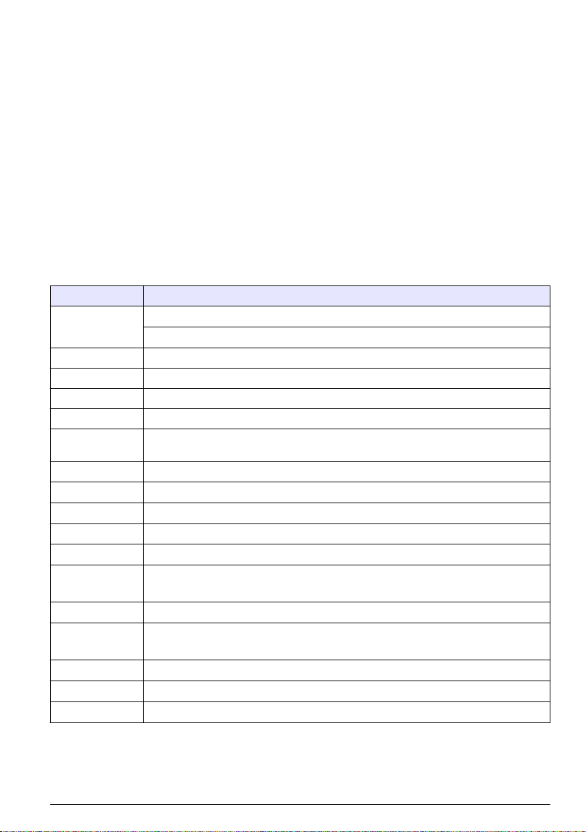
目录
规格 第 69 操作 第 80
基本信息 第 71 维护 第 82
安装 第 73 诊断和故障排除 第 83
粒子计数器导航 第 79
附加信息
制造商网站中提供了附加信息
规格
产品规格如有变化,恕不另行通知。
仪器规格
规格 详细信息
电源要求 适配器(包括在出货套件内):100–240 VAC、2.5 A、50–60 Hz
仪器:24 VDC、75 W(最大值)
安装类别
保护等级
污染程度
海拔
光源 具有 10 年平均故障时间 (MTTF) 的 Long Life Laser™ 二极管、3B 类激光、810 至 852 nm、
取样泵类型 真空泵,适用于连续使用
计数显示 ¼ VGA TFT 彩色触摸屏
界面 基于 Windows 的 CE
显示的最大计数
延迟时间 00:00:06 至 23:59:59
取样和保持时间 取样:00:00:01 至 23:59:59
计数警报 1 到 9,999,999 颗
数据存储 50 到 5000 个样品,可在“历史数据”审阅屏幕滚动
计数周期 在自动模式中最多 100
取样点 最多 999
排气口 3/8 英寸 NPT 螺纹
I
III
2
2000 m (6562 ft)
50 mW(最大值)
®
9,999,999
保持:00:00:00 至 23:59:59
3000 为默认值
中文
69
Page 70

规格 详细信息
输出
多支管 支持 A3432,32 个端口的多支管系统(仅适用于 1 CFM 装置)
外壳材料 不锈钢
重量(不含电池) 3413 和 3415—7.55 kg (16.6 lb)
尺寸(宽 x 长 x 高)
操作环境 0 至 40 °C(32 至 104 °F);10 至 90% 相对湿度,无冷凝
存储环境 –40 至 50 °C(–40 至 122 °F);0 至 98% 相对湿度,无冷凝
Ethernet–10Base-T/100Base-TX
RS485 串行
RS232 串行
可选无线–兼容 802.11 b/g
USB 客户端(1.1 版)
USB 主机(1.1 版)
3423 和 3425—8.33 kg (18.3 lb)
3445—8.65 kg (19.0 lb)
31.8 x 25.4 x 20.3 cm (12.5 x 10 x 8 in.)
取样测量规格
取样
粒径范围数量 标准 6、8
粒径范围和标准通道 型号 3413 和 3423—0.3、0.5、1.0、3.0、5.0、10.0 µm
型号 3415 和 3425—0.5、1.0、2.0、3.0、5.0 和 10.0 或 25.0 µm
型号 3445—0.5、1.0、2.0、3.0、5.0、10.0 µm
流速 型号 3413 和 3415—28.3 L/min (1.00 cfm) ± 5%(默认出厂设置)
型号 3423 和 3425—50 L/min (1.77 cfm) ± 5%(默认出厂设置)
型号 3445—100 L/min (3.53 cfm) ± 5%(默认出厂设置)
零计数 遵从 JIS B9921。1 次计数或少于 5 分钟,置信度 95%
符合误差 型号 3413 和 3415—20,000,000 粒/立方米(566,570 粒/立方英尺)时为 10%
型号 3423 和 3425—10,000,000 粒/立方米(283,280 粒/立方英尺)时为 10%
型号 3445—5,000,000 粒/立方米(141,640 粒/立方英尺)时为 10%
计数效率 型号 3413 和 3423—0.3 µm 为 50% ± 20 %(最低敏感度的 1.5 倍时为 100% ± 10%)。严
格遵从 ISO21501-4。
型号 3415、3425 和 3445—0.5 µm 为 50% ± 20 %(最低敏感度的 1.5 倍时为 100% ±
10%)。严格遵从 ISO21501-4。
70
中文
Page 71

电池规格
规格 详细信息
电池类型 锂离子智能电池;可以充电、弹出和更换,且不会中断系统。
附送数量 一块(3445 提供两块电池)
操作期间电池寿命 型号 3413 和 3415—6 小时
型号 3423 和 3425—7 小时
型号 3445—3.5 小时
电池充电时间 最短 6.75 小时,最长 10 小时
电源 14.4 VDC,6.6 Ah (2x)
电池重量
0.66 kg (1.45 lb)
基本信息
对于因本手册中的任何不足或遗漏造成的直接、间接、特别、附带或结果性损失,制造商概不负责。制
造商保留随时更改本手册和手册中描述的产品的权利,如有更改恕不另行通知或承担有关责任。修订版
可在制造商的网站上找到。
安全信息
注 意
对于误用和滥用造成的产品损坏,制造商概不负责,包括但不限于:直接、附带和间接的损坏,并且对于适用法律
允许的最大程度的损坏也不承担任何责任。用户唯一的责任是识别重大应用风险和安装适当的系统,以在设备可能
出现故障时保护流程。
请在拆开本设备包装、安装或使用本设备前,完整阅读本手册。特别要注意所有的危险警告和注意事
项。否则,可能会对操作者造成严重的人身伤害,或者对设备造成损坏。
确保设备提供的保护没有受损。请勿以本手册指定方式之外的其它方式使用或安装本设备。
危险信息使用
表示潜在的或紧急的危险情况,如果不加以避免,将会导致死亡或严重伤害。
危 险
警 告
表示潜在或非常危险的情形,如不避免,可能导致严重的人身伤亡。
表示潜在的危险情形,可能导致一定程度的人身伤害。
表明如不加以避免则会导致仪器损坏的情况。需要特别强调的信息。
警 告
注 意
中文
71
Page 72

警告标签
请阅读贴在仪器上的所有标签和标记。如未遵照这些安全标签的指示操作,则可能造成人身伤害或仪器
损坏。仪器上的符号在手册中通过警告说明参考。
本符号如果出现在仪器中,则表示参考说明手册中的操作和/或安全信息。
仪器外壳或绝缘体上如有此标志,则表示存在触电或电击致死的风险。
静电会损害精密的内部电子组件,从而导致仪器性能降低或最终出现故障。
此标志指示设备中使用激光装置。
此标志指出保险丝或限流装置的位置。
使用此符号标记的电气设备在 2005 年 8 月 12 日后,不能通过欧洲公共垃圾系统进行处理。为遵守
欧洲地区和国家法规(欧盟指令 2002/96/EC),欧洲电气设备使用者现在必须将废弃或到期的设备
送还制造商进行处理,使用者不必支付任何费用。
注: 如果退回产品是为了进行再循环,请联系设备生产商或供应商,索取如何退回使用寿命到期的设备、生产商提
供的电源附件以及所有辅助部件的说明,以便进行适当处理。
合规
此标志指示仪器为 1 类激光产品。
除了符合 2007 年 6 月 24 日颁布的第 50 号激光公告规定的偏差,本产品还符合 IEC/EN
60825-1:2007 和 21 CFR 1040.10 的规定。FDA 认证市场准入号:9020917。
本产品还符合 CE 规定。有关完整的合规详情,请联系制造商。
Wi-Fi 设备的国家特定许可
警 告
电磁辐射危险。正常使用时,确保所有人员与天线保持 20 cm (7.9 in) 的最小距离。天线不能与其它任何
天线或发射器放在一起或一同操作。
具有无线选项的产品包含在 2.4 GHz 范围内操作的模块式 Wi-Fi 设备。
• 美国 FCC ID:R68WIPORTG
• 加拿大 IC ID:3867A-WIPORTG
国家 ISO31662 字母代码 国家 ISO31662 字母代码
奥地利
比利时
丹麦
72
中文
AT
BA
DK
波兰
葡萄牙
西班牙
PL
PT
ES
Page 73

国家 ISO31662 字母代码 国家 ISO31662 字母代码
芬兰
法国
德国
希腊
匈牙利
爱尔兰
意大利
墨西哥
FI
FR
DE
GR
HU
IE
IT
MX — —
瑞典
英国
冰岛
挪威 否
瑞士
土耳其
荷兰
SE
GB
IS
CH
TR
NL
监管 RF 设备审批
• FCC:由 TCB Grant of Authorization 批准为模块式设备 FCC ID:R68WIPORTG
• IC:由 Certificat D'Acceptabilite' Technique C-REL ID 批准为模块式设备:3867A-WIPORTG
意见:根据(2 类设备)条款 10(5) 和 附录 IV 中的评估步骤,须符合条款 3.2 基本要求的 R&TTE 指令
1999/5/EC,并标记为 CE1177。
认证
本设备符合 FCC 规定第 15 部分以及加拿大工业部许可豁免 RSS 标准的要求。设备操作满足以下两
个条件:
1. 本设备不会造成有害干扰。
2. 本设备必须接受任何接收到的干扰,包括可能导致意外操作的干扰。
若未经负责出具符合声明的一方明确同意,擅自对本无线通讯设备进行改动或改装,可能会导致取消用
户操作该设备的权限。如果对本设备进行任何更改,将意味着终止加拿大工业部认证和 FCC 授权。
一般产品信息
本手册介绍 MET ONE 3400 系列粒子计数器的使用。MET ONE 3400 系列粒子计数器用于计数和测
量洁净室环境中尘埃粒子的粒径。请参阅 表 1。
表 1 MET ONE 3400 系列粒子计数器型号
型号 流速 最小粒径通道 (µm)
L/min Ft3/min
3413 28.3 1 0.3
3415 28.3 1 0.5
3423 50 1.77 0.3
3425 50 1.77 0.5
3445 100 3.53 0.5
安装
警 告
多种危险。只有合规的专业人员才能从事文件中本部分所述的任务。
中文
73
Page 74

仪器拆箱
从装运箱中取出所有物品,并检查是否有损坏。如果有任何物品丢失或损坏,请联系制造商。请参阅
图 1。
图 1 MET ONE 3400 组件
1 3400 系列粒子计数器 8 采样管
2 可充电电池 (280-120-2024) 9 零计数过滤器
3 交流到直流电源 (280-300-5000) 10 RS485 插接器
4 电源线(美式) 11 USB 闪存盘
5 电源线(欧式) 12 吸气管嘴清洁刷
6 用于打印机的热敏纸卷 (2x) 13 Wi-Fi 无线天线
7 等动力探头 14 用于触摸屏界面的笔针
接线安全信息
警 告
电击致命危险。确保可轻松切断本地电源。
注 意
进行电气连接前,务必断开仪器的电源。
对仪器进行连接时,请遵从所有安装声明。
74
中文
Page 75

静电放电 (ESD) 注意事项
注 意
可能导致仪器损坏。静电会损害精密的内部电子组件,从而导致仪器性能降低或最终出现故障。
请参阅此流程中的步骤以防止 ESD 损坏仪器:
• 接触接地金属表面(如仪器外壳、金属导管或管道),以将静电排出机壳外。
• 避免过度移动。运送静电敏感的组件时,请使用抗静电容器或包装。
• 配戴连接到接地线缆的腕带。
• 使用抗静电地板垫和工作台垫,以使工作区具备静电安全性。
电气连接
如图 2 和图 3 所示,连接探头、外部电源、电缆和 USB 设备。
图 2 背面视图
1 排气口 4 多支管控制器接头或标准 RS232 端口(仅适用于
1 CFM 装置)
2 串行通信 RS485 接头 5 电池端口
3 过滤器扫描探头的辅助 I/O 端口 6 辅助支脚
中文
75
Page 76
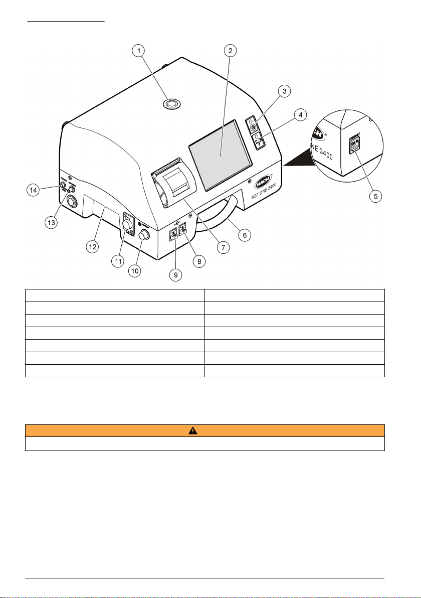
图 3 正面和侧面视图
1 取样吸气管嘴 8 USB 主机接头
2 触摸屏 9 USB 客户端接头
3 电源按钮 10 相对湿度和温度传感器接头
4 电池状态指示器 11 空气流速传感器接头
5 以太网接头 12 把手
6 把手 13 无线天线接头
7 打印机 14 电源接头
注: 为获得最佳结果,请使用制造商提供的
与客户服务部联系。
USB
闪存盘。如需其他支持,请致电
·800.866.7889 或 +1.541.472.6500
,
安装电池
警 告
爆炸危险。为避免火灾和/或爆炸,请仅使用制造商指定的电池型号和电源/充电器。有关部件号,请参阅图 1 第 74。
76
中文
Page 77

1 2
3 4
中文
77
Page 78

组装粒子计数器系统
图 4 显示粒子计数器系统的设置。
图 4 粒子计数器组装
78
中文
Page 79

安装打印纸
为防止损坏打印机,请始终在打印机中安装建议的热敏纸时操作粒子计数器。如果粒子计数器必须在没
有纸时使用,请将打印模式设置为“无”。要安装一卷热敏打印纸,请参阅图 5。
图 5 安装打印纸
粒子计数器导航
用户可以从“计数器导航”屏幕中访问粒子计数器的功能。表 2 显示通过导航屏幕可访问的功能。
表 2 屏幕图标说明
图标 功能 说明
取样 测量粒子计数。请参阅 测量粒子计数 第 80。
历史 审阅存储器中的测量结果;打印、导出或筛选数据。有关信息,请参阅光盘。
导出 以逗号分隔值 (CSV)、制表符分隔或 PortAll 文件输出文件。有关信息,请参阅光盘。
打印机 打印取样数据作为硬拷贝。请参阅 如何使用“打印中心” 第 81。
中文
79
Page 80

图标 功能 说明
取样点 添加/编辑/移除区域;复制取样点设置、编辑取样点设置;编辑特定取样点的警报。有关信息,
请参阅光盘。
组 加载/添加/编辑组;删除组。有关信息,请参阅光盘。
表 2 屏幕图标说明 (续)
系统 时间/日期;睡眠时间/背光超时;设置登录要求;设置警报声音;管理用户;设置流速单位;
粒径 添加/编辑/删除粒径(可选)。有关信息,请参阅光盘。
测试向导 ISO、EU-GMP、FS 或 BS 分类遵从性的测试与报告向导. 有关信息,请参阅光盘。
返回 返回至上一屏幕或菜单.
管理数据存储器。有关详情,请参阅光盘。有关信息,请参阅光盘。
操作
登录到粒子计数器
先决条件
• 启动系统。
1. 如果需要,用手指或笔针激活背光。
2. 按锁定图标可注销上一个用户。再次按锁定可看到登录屏幕。
3. 输入用户名和密码。确认。
注: 按
Alt
键访问特殊字符。
测量粒子计数
完整的粒子计数测量后,测量到的粒子数目将显示在屏幕上并作为数据存储。相对湿度、温度和空气流
速等其他配置的参数将显示并存储在数据中。
1. 请取下计数器入口管上的防护帽。
2. 在“计数器导航”屏幕上,按样品。
3. 要开始粒子计数,请按运行按钮。在测量计数时,运行按钮将更改为停止按钮。
注: 在计数完成之前,按停止可结束测试。不完整的粒子计数数据不会存储或打印。
4. 计数测量完成后,测试将自动停止。
更改粒子计数取样点
有两种方法可更改粒子计数的取样点。
• 在“取样”屏幕上,按取样点名称。选择新取样点名称,然后确认。
• 在“取样”屏幕上,按加号按钮以增加取样点,或按减号按钮以减少取样点。
80
中文
Page 81

粒子计数期间查看设置
用户可以在粒子计数周期的任何时候查看取样点和组设置。
• 在“取样”屏幕上,选择屏幕右侧的“设置”选项卡。
粒子计数期间查看历史数据
用户可以在粒子计数周期的任何时候查看历史取样数据。
1. 在“取样”屏幕上,按箭头按钮。
2. 选择历史数据图标可查看数据。
使用过滤器扫描探头
注 意
过滤器扫描探头功能仅适用于 1 CFM 和 50 LPM 设备。
1. 在“计数器导航”屏幕上,按样品。
2. 在“测试”屏幕上,按过滤器图标。
3. 要开始测试,请按启动过滤器探头测试。
4. 要结束测试,请按停止过滤器探头测试。
5. 按打印机生成上次完成的测试的简短报告。
如何使用“打印中心”
关于“打印中心”
注 意
为避免损坏打印机,切勿在没有纸时操作打印机。如果粒子计数器必须在没有纸时使用,请务必将打印模式设置为
“无”。
粒子计数器具有内置打印机。用户可以通过以下途径访问“打印中心”屏幕:
• “计数器导航”屏幕
• “历史”屏幕
• “系统诊断”屏幕
• “测试/报告向导”屏幕
• “区域/取样点设置”屏幕
在“打印中心”屏幕中,用户可以:
• 设置自动打印功能
• 打印存储器记录或平均计数
注: 从“历史”屏幕中打印筛选的数据。
手动打印记录
存储器最多可保留 5000 条记录。“打印中心”可打印整个存储器或计数周期的平均值。手动打印记录:
1. 在“计数器导航”屏幕上,按打印机。
2. 在“打印中心”屏幕中,选择数据打印选项。
3. 数据将开始打印。
• 要取消打印作业,请按取消打印。
• 要返回“计数器导航”,请按返回。
中文
81
Page 82

设置自动打印功能
注: 如果取样周期非常短暂,且保持时间为零,则可能跳过某些取样数据。
1. 在“计数器导航”屏幕上,按打印机。
2. 在“打印中心”屏幕中,选择“取样打印模式”字段。选择自动打印选项。
选项 说明
None(无) 不会自动打印任何数据
警报 在超过计数警报时,打印结果
周期 打印第一个计数周期及多个已编程计数周期的结果
All(所有) 完成每个计数周期后,打印结果
3. 按 ENTER 确认。
维护
警 告
多种危险。请勿拆卸仪器进行维护或维修。如果必须清洁或维修内部组件,请联系制造商。
存在人身伤害危险。只有合格的专业人员,才能从事手册此处所述的工作。
清洁仪器外部
可以根据需要清洁仪器外部。为了避免人员暴露于潜在危险的化学物质,请务必在接触化学物质后立即
清洁触摸屏。
切勿在仪器或触摸屏上遗留可见的水分。水分可能渗透触摸屏并损坏内部的电子线路。
警 告
注 意
1. 在取样吸气管嘴上加盖。
2. 在软布上喷洒中性的清洁液。小心擦拭仪器的外部。
3. 用柔软干布擦拭触摸屏表面。如果需要,请用中性的清洁液弄湿软布。
将计数设为零
粒子计数异常高后,请执行此步骤。此步骤将确认粒子计数器是否正常工作,并将移除剩余粒子。
1. 将零计数过滤器放在吸气管上。请参阅 图 1 第 74。
2. 开启装置并根据需要登录。
3. 按取样。
4. 按运行。
5. 重复此流程,直到粒子计数恢复零。
对粒子计数器中的电池充电。
在连接交流电源线时,3400 中的电池将开始充电。在仪器中完全充电需要大约 10 小时。在电池显示屏
显示充电介于 95% 与 100% 之间时,电池视为完全充电。
82
中文
Page 83

先决条件:将电池装入仪器中。请参阅 安装电池 第 76。
注 意
根据本地法规丢弃废旧电池或联系制造商。请勿将用完的电池放入生活垃圾中。
1. 将电源连接到装置。请参阅 图 3 第 76。
2. 使用交流电适配器将装置电源连接到外接电源。
电池状态灯将显示电池中的电量级别。请参阅 表 3。
表 3 电池 LED 指示灯颜色指示
LED 指示灯状态 LED 指示灯颜色 电池状态 充电状态
闪烁中 橙色 电池电量低 未充电
闪烁中 绿色 电池电量低 充电中
常亮 绿色 充电完毕 充电中
诊断和故障排除
“诊断”屏幕会显示故障排除可能需要的信息。表 4 显示“诊断”屏幕上的故障通知示例。
表 4 “系统诊断”屏幕例示 - 时钟电池故障
信号 值 Status(状态)
Calibration 0.00 VDC
流量
时钟电池
电池 1(底部)
电池 2(顶部)
激光电流
0.00 VDC
0.00 VDC FAIL
16.42 VDC
16.44 VDC
N/A – –
OFF(关闭)
OFF(关闭)
PASS(正常)
PASS(正常)
对于需制造商提供技术支持的故障排除,用户可能需要将系统状态打印输出传真给技术支持人员。
1. 在“计数器导航”屏幕上,按诊断。
2. 转到计数器选项卡以查看系统信息,如序列号、型号和校准日期。
3. 转到校准选项卡以查看当前校准信息。
4. 在“诊断”屏幕上,按打印。
打印输出将显示序列号、日期和时间以及系统的其他数据。
中文
83
Page 84

目次
仕様 ページの 84 操作 ページの 96
総合情報 ページの 86 メンテナンス ページの 98
設置 ページの 89 診断およびトラブルシューティング ページの 99
パーティクルカウンタナビゲーション ページの 95
より詳しい情報
より詳しい情報は、当社 Web サイトにて入手できます。
仕様
この仕様は予告なく変更されることがあります。
装置の仕様
項目 仕様
電源要件 アダプタ (出荷キットに同梱):100~240 VAC、2.5 A、50~60 Hz
装置:24 VDC、最大 75 W
取り付けカテゴリ
保護クラス
汚染度
高度 2000 m (6562 フィート)
光源 平均故障時間 (MTTF) が 10 年の Long Life Laser™ (長寿命レーザー) ダイオード、
ポンプの種類 真空装置、連続使用定格
カウント表示 ¼VGA TFT カラータッチ画面
インターフェース Windows CE® ベース
最大表示カウント
遅延時間 00:00:06~23:59:59
サンプルおよびホールド時間 サンプル:00:00:01~23:59:59
カウントアラーム 1~9,999,999 カウント
データメモリー 50~5000 サンプル、[履歴データ] レビュー画面でスクロール可能
カウントサイクル 自動モードで最大 100
場所 最大 999
排気口 3/8 インチの NTP スレッド
I
III
2
クラス 3B レーザー、810~852 nm、最大 50 mW
9,999,999
ホールド:00:00:00~23:59:59
3000 がデフォルト値
84
日本語
Page 85

項目 仕様
出力 イーサネット:10Base-T/100Base-TX
RS485 シリアル
RS232 シリアル
オプションの無線:802.11 b/g 互換
USB クライアント(バージョン 1.1)
USB ホスト(バージョン 1.1)
マニフォールド A3432 をサポート、32 ポートマニフォールドシステム (1 CFM 単位でのみ利用可
筐体材料 ステンレス鋼
重量(バッテリなし) 3413 および 3415:7.55 kg (16.6 lb)
サイズ(幅 x 奥行 x 高さ) 31.8 x 25.4 x 20.3 cm (12.5 x 10 x 8 インチ.)
環境、運転時 0~40°C (32~104°F)、相対湿度 10~90%、結露なきこと
環境、保管時 -40 ~ 50°C (-40 ~ 122 °F)、相対湿度 0 ~ 98%、結露なきこと
能)
3423 および 3425:8.33 kg (18.3 lb)
3445:8.65 kg (19.0 lb)
サンプル測定の仕様
サンプリング
サイズ範囲数 標準 6、8
パーティクルサイズ範囲と標
準チャンネル
流量 モデル 3413 および 3415:28.3 L/分(1.00 cfm) ±5% (デフォルトの工場設定)
ゼロカウント JIS B9921 準拠。5 分以内に 1 カウント未満、信頼度 95%
同時計数損失 モデル 3413 および 3415:10%、20,000,000 パーティクル/m3 (566,570 パーテ
カウント効率 モデル 3413 および 3423:0.3 µm に対し 50%±20% (最低感度の 1.5 倍で 100%
モデル 3413 および 3423:0.3、0.5、1.0、3.0、5.0、10.0 µm
モデル 3415 および 3425:0.5、1.0、2.0、3.0、5.0 および 10.0 または 25.0 µm
モデル 3445:0.5、1.0、2.0、3.0、5.0、10.0 µm
モデル 3423 および 3425:50 L/分(1.77 cfm) ±5% (デフォルトの工場設定)
モデル 3445:100 L/分(3.53 cfm) ±5% (デフォルトの工場設定)
ィクル/フィート3)
モデル 3423 および 3425:10%、10,000,000 パーティクル/m3 (283,280 パーテ
ィクル/フィート3)
モデル 3445:10%、5,000,000 パーティクル/m3 (141,640 パーティクル/フィー
ト3)
±10%)。ISO21501-4 に完全準拠
モデル 3415、3425 および 3445:0.5 µm に対し 50%±20% (最低感度の 1.5 倍で
100%±10%)。ISO21501-4 に完全準拠
日本語
85
Page 86

バッテリの仕様
項目 仕様
バッテリの種類 リチウムイオン小型バッテリ、システムを中断せずに充電、取り出しおよび交換可能。
梱包数量 1 個 (3445 には 2 個のバッテリが同梱)
動作中のバッテリ寿命 モデル 3413 および 3415:6 時間
モデル 3423 および 3425:7 時間
モデル 3445:3.5 時間
バッテリ充電時間 最小 6.75 時間、最大 10 時間
電源 14.4 VDC、6.6 Ah (2x)
バッテリ重量
0.66 kg (1.45 lb)
総合情報
いかなる場合も、製造元は、例えそのような損害が生じる可能性について報告を受けていたとして
も、本マニュアルに含まれるいかなる瑕疵または脱落から生じる直接的、間接的、特定、付随的また
は結果的に生じる損害に関して責を負いません。製造元は、通知または義務なしに、随時本マニュア
ルおよび製品において、その記載を変更する権利を留保します。改訂版は、製造元の Web サイト上
にあります。
安全情報
告 知
メーカーは、本製品の目的外使用または誤用に起因する直接損害、偶発的損害、結果的損害を含むあらゆる損害
に対して、適用法で認められている範囲で一切責任を負わないものとします。ユーザーは、適用に伴う危険性を
特定したり、装置が誤作動した場合にプロセスを保護するための適切な機構を設けることに関して、全責任を負
うものとします。
この機器の開梱、設定または操作を行う前に、このマニュアルをすべてよく読んでください。危険お
よび注意の注意事項に注意を払ってください。これを怠ると、オペレータが重傷を負う可能性、ある
いは機器が損傷を受ける可能性があります。
本装置に備わっている保護機能が故障していないことを確認します。本マニュアルで指定されてい
る以外の方法で本装置を使用または設置しないでください。
危険情報の使用
回避しなければ死亡または重傷につながる、潜在的または切迫した危険な状況を示します。
危 険
警 告
避けない場合、死亡事故や負傷が起こるかも知れない危険な状況を示します。
軽傷または中傷事故の原因となる可能性のある危険な状況を示しています。
回避しなければ、装置の損傷を引き起こす可能性のある状況を示します。 特に注意を要する情報。
86
日本語
注 意
告 知
Page 87

使用上の注意ラベル
装置に取り付けてあるラベルとタグをすべてお読みください。これを怠ると、人身傷害や装置の損傷
につながる恐れがあります。測定器に記載されたシンボルは、使用上の注意と共にマニュアルを参照
してください。
このシンボルが測定器に記載されている場合、操作用の指示マニュアル、または安全情報を参照
してください。
このシンボルが製品筐体またはバリア上に表示されている場合、感電の危険があり、場合によっ
ては感電死の原因となる恐れのあることを示しています。
静電気による装置内部の精密電子部品の破損により、装置の性能低下や故障を招く恐れがありま
す。
このシンボルは、機器内でレーザーデバイスが使用されていることを示します。
このシンボルによりヒューズまたは限流器の場所が識別されます。
このシンボルが表示された電気機器は、欧州廃棄システムにより 2005 年 8 月 12 日以降の廃棄処
分が禁じられています。欧州地域規制および国内規制 (EU 指令 2002/96/EC) に従い、欧州の電気
機器ユーザーは古くなったまたは使い切った機器をメーカーに無償返却する必要があります。
注: リサイクルのために返却する際には、機器の製造者または販売業者に連絡を取り、使用済みの機器、製造者に
供給された電気付属品、ならびにすべての補助品を適切に廃棄するための指示を受けてください。
規格準拠
このシンボルは、装置がクラス 1 レーザー製品に含まれ
ることを示します。
この製品は、IEC/EN 60825-1:2007 および 21 CFR 1040.10 に準拠しています (2007 年 6 月 24 日付
けの Laser Notice No. 50 による偏差に関する準拠を除く)。FDA 登録番号:9020917。
また、本製品は CE に準拠しています。完全な規格準拠の詳細は製造元に問い合わせてください。
Wi-Fi デバイスの国別認証
注 意
電磁放射の危険。通常の使用で、アンテナがあらゆる人から少なくとも 20 cm 離れていることを確認し
てください。アンテナを、他のアンテナまたはトランスミッターと一緒に配置または操作することはで
きません。
無線オプションのある製品には、2.4 GHz の範囲で動作するモジュール型 RF Wi-Fi デバイスが含ま
れています。
• 米国 FCC ID: R68WIPORTG
• カナダ IC ID: 3867A-WIPORTG
国 ISO31662 文字コード 国 ISO31662 文字コード
オーストリア
ベルギー
AT
BA
ポーランド
ポルトガル
PL
PT
日本語
87
Page 88

国 ISO31662 文字コード 国 ISO31662 文字コード
デンマーク
フィンランド
フランス
ドイツ
ギリシャ
ハンガリー
アイルランド
イタリア
メキシコ
DK
FI
FR
DE
GR
HU
IE
IT
MX — —
スペイン
スウェーデン
英国
アイスランド
ノルウェイ
スイス
トルコ
オランダ
ES
SE
GB
IS
NO
CH
TR
NL
規制 RF デバイス承認
• FCC:認証に関する TCB 認可の下でモジュール型デバイスとして承認されました。FCC ID:
R68WIPORTG
• IC:Certificat D'Acceptabilite' Technique C-REL ID : 3867A-WIPORTG 下でモジュール型デバイス
として承認されました
見解:(クラス 2 機器)用の条項 10(5) および付属書 IV の評価手順に従い、CE1177 としてマークさ
れ、条項 3.2 の必要不可欠な要件への R&TTE 指令 1999/5/EC の下に準拠。
取得認証
この機器は FCC 規則のパート 15、およびカナダ産業省が免許不要の無線機器について定めた RSS
規格に準拠します。運転は以下の条件を前提としています:
1. この装置が有害な干渉の原因とならないこと。
2. この装置が望ましくない動作の原因となる可能性のあるいかなる干渉にも対応しなければなりま
せん。
これらの規格への準拠に責任を持つ当事者による明示的承認を伴わなずにこの無線通信機器に対す
る改変または改造を行うと、ユーザーはこの機器を使用する権限を失う可能性があります。機器に変
更を加えると、カナダ産業省および FCC の認証が無効になります。
総合製品情報
本マニュアルは、MET ONE 3400 シリーズパーティクルカウンタの使用について説明しています。
MET ONE 3400 シリーズパーティクルカウンタは、クリーンルーム環境中の浮遊パーティクルをカ
ウントしてそのサイズを測定します。表 1 を参照してください。
表 1 MET ONE 3400 シリーズパーティクルカウンタのモデル番号
モデル番号 流量 最小パーティクルサイズチャンネル (µm)
L/分 フィート3/分
3413 28.3 1 0.3
3415 28.3 1 0.5
3423 50 1.77 0.3
3425 50 1.77 0.5
3445 100 3.53 0.5
88
日本語
Page 89

設置
警 告
複合的な危険。本書のこのセクションに記載されている作業は、必ず資格のある要員が行う必要があり
ます。
装置の開梱
出荷コンテナからすべての品目を取り出し、破損がないか検査します。 欠品もしくは損傷している場
合は、製造元に連絡してください。図 1 を参照してください。
日本語
89
Page 90

図 1 MET ONE 3400 構成部品
1 3400 シリーズパーティクルカウンタ 8 等速吸引プローブ用延長チューブ
2 充電バッテリ (280-120-2024) 9 ゼロカウントフィルタ
3 AC-to-DC 電源 (280-300-5000) 10 RS485 コネクタアセンブリ
4 電源コード(US) 11 USB フラッシュドライブ
5 電源コード(EU) 12 吸入クリーニングブラシ
6 プリンタ用の感熱紙ロール (2x) 13 Wi-Fi 用の無線アンテナ
7 等速吸引プローブ 14 タッチスクリーンインターフェース用のスタイラ
ス
配線にあたっての安全
警 告
感電死の危険。ローカル電源切断へのアクセスが容易であることを確認します。
告 知
電気配線を接続する前に必ず装置の電源を切断してください。
装置への接続が行われる間は、すべての安全に関する記載事項に従ってください。
90
日本語
Page 91

静電気放電(ESD)への配慮
告 知
装置の損傷の可能性。静電気による装置内部の精密な電子コンポーネントの破損により、装置の性能低
下や故障を招く恐れがあります。
以下の手順を参照して、ESD による装置の損傷を回避してください。
• 機器のシャーシ、金属製導管/パイプなど、接地された金属の表面を触り、体から静電気を放電し
ます。
• 過度な移動を避けます。静電気に敏感なコンポーネントは静電気防止コンテナや包装材内に入れ
て運搬してください。
• 接地線で接続したリストストラップを身に付けます。
• 静電気防止フロアパッドおよび作業台パッドがある、静電気が発生しない場所で作業します。
電気的接続
図 2 および 図 3 に表示されるとおりに、プローブ、外部電源、ケーブルおよび USB デバイスに接続
します。
図 2 背面図
1 排気口 4 マニフォールドコントローラコネクタまたは標準
RS232 ポート (1 CFM ユニットでのみ使用可能)
2 シリアル通信 RS485 コネクタ 5 バッテリポート
3 フィルタスキャンプローブ用の補助 I/O ポート 6 縦置き用足
日本語
91
Page 92

図 3 前面と側面図
1 サンプル吸入ノズル 8 USB ホストコネクタ
2 タッチスクリーン 9 USB クライアントコネクタ
3 電源ボタン 10 相対湿度と温度プローブコネクタ
4 バッテリステータスインジケータ 11 気流速度プローブコネクタ
5 イーサネットコネクタ 12 ハンドル
6 ハンドル 13 無線アンテナコネクタ
7 プリンタ 14 電源コネクタ
注: 最善の結果を得るには、製造元が供給する
するカスタマーサービスについては、
USB
800.866.7889
フラッシュドライブを使用してください。追加のサポートに関
または
+1.541.472.6500
にお問い合わせください。
バッテリの取り付け
警 告
爆発の危険。火災や爆発を避けるために、製造元が指定したバッテリの種類および電源/充電のみを使用してくだ
さい。部品番号については、図 1 ページの 90 を参照してください。
92
日本語
Page 93

1 2
3 4
日本語
93
Page 94

パーティクルカウンタシステムの組み立て
図 4 はパーティクルカウンタシステムのセットアップを示します。
図 4 パーティクルカウンタアセンブリ
94
日本語
Page 95

プリンタ用紙の取り付け
プリンタの損傷を避けるために、必ず推奨される感熱紙をプリンタに取り付けた状態でパーティクル
カウンタを操作します。給紙せずにパーティクルカウンタを使用する必要がある場合は、印刷モード
を「なし」に設定します。印刷用感熱紙のロールを取り付けるには、図 5 を参照してください。
図 5 プリンタ用紙の取り付け
パーティクルカウンタナビゲーション
パーティクルカウンタの機能には、[カウンタのセットアップ] 画面からアクセスします。表 2 は、ナ
ビゲーション画面を介してアクセス可能な機能を示します。
表 2 画面アイコンの説明
アイコン 機能 説明
測定 パーティクルカウントを測定します。パーティクルカウントの測定 ページの 96 を参
履歴 バッファ内の測定結果をレビューして、データの印刷、エクスポートまたはフィルタ適
エクスポートカンマ区切り (CSV)、タブ区切り、または PortAll 形式でファイルを出力します。詳細
照してください。
用を実行します。詳細は、CD を参照してください。
は、CD を参照してください。
日本語
95
Page 96

アイコン 機能 説明
プリンタ サンプルデータのハードコピーを印刷します。印刷センターの使用方法 ページの 97
を参照してください。
表 2 画面アイコンの説明 (続き)
場所 領域の追加/編集/削除、場所設定のコピーや編集、指定場所のアラームの編集。詳細は、
グループ グループのロード/追加/編集、グループの削除。詳細は、CD を参照してください。
システム 時刻/日付、スリープ時間/バックライトのタイムアウト、ログオン要件の設定、アラーム
サイズ サイズの追加/編集/削除 (オプション)。詳細は、CD を参照してください。
テストのウ
ィザード
戻る 直前の画面またはメニューに戻ります。
CD を参照してください。
音の設定、ユーザーの管理、流量単位の設定、データバッファの管理。詳細は、CD を
参照してください。詳細は、CD を参照してください。
ISO、EU-GMP、FS、または BS 分類準拠用のテストとレポートのウィザード。詳細は、
CD を参照してください。
操作
パーティクルカウンタにログオン
必要条件
• システムを起動します。
1. 必要に応じて、指やスタイラスでバックライトをアクティブにします。
2. 以前のユーザーをログアウトするには、[LOCK (ロック)] アイコンを押します。再び [LOCK (ロ
ック)] を押して [ログオン] 画面を表示します。
3. ユーザー名とパスワードを入力します。確定します。
注: 特殊文字にアクセスするには、
[Alt]
キーを押します。
パーティクルカウントの測定
パーティクルカウント測定の完了後、パーティクルの数が画面に表示され、データとして保存されま
す。相対湿度、温度および気流速度などの他の構成パラメータが表示され、データに保存されます。
1. カウンタのサンプル吸引口から保護キャップを取り外します。
2. [カウンタのセットアップ] 画面で、[SAMPLE (測定)] を押します。
3. パーティクルカウントを開始するには、[RUN (実行)] ボタンを押します。カウント測定中は、
[RUN (実行)] ボタンが [STOP (停止)] ボタンに変わります。
注: カウント完了前にテストを終了するには、
全な場合は、保存や印刷が実行されません。
4. カウント測定完了時に、テストが自動的に停止します。
96
日本語
[STOP (停止)]
を押します。パーティクルカウントデータが不完
Page 97

パーティクルカウントの場所の変更
パーティクルカウントの場所を変更するには 2 つの方法があります。
• [測定] 画面で、場所の名前を押します。新しい場所の名前を選択して確定します。
• [測定] 画面で、[PLUS (プラス)] ボタンを押して場所をインクリメントするか、[MINUS (マイナス)]
ボタンを押して場所をデクリメントします。
パーティクルカウント中の設定の参照
パーティクルカウントサイクル中にいつでも場所とグループの設定を参照できます。
• [測定] 画面で、画面右側の [設定] タブを選択します。
パーティクルカウント中の履歴データの参照
パーティクルカウントサイクル中にいつでも履歴サンプルデータを参照できます。
1. [測定] 画面で、[ARROW (矢印)] ボタンを選択します。
2. [HISTORICAL DATA (履歴データ)] アイコンを選択してデータを参照します。
フィルタスキャンプローブの使用
告 知
フィルタスキャンプローブ機能は、1 CFM ユニットと 50 LPM ユニットにのみ適用されます。
1. [カウンタのセットアップ] 画面で、[SAMPLE (測定)] を押します。
2. [テスト] 画面で、[FILTER (フィルタ)] アイコンを押します。
3. テストを開始するには、[START FILTER PROBE TEST (フィルタプローブテストの開始)] を押し
ます。
4. テストを終了するには、[STOP FILTER PROBE TEST (フィルタプローブテストの終了)] を押し
ます。
5. 最後に完了したテストの短いレポートを生成するには、[PRINTER (プリンタ)] を押します。
印刷センターの使用方法
印刷センターについて
告 知
プリンタの損傷を避けるために、給紙せずにプリンタを操作しないでください。給紙せずにパーティクルカウン
タを使用する必要がある場合は、印刷モードを「なし」に設定してください。
パーティクルカウンタには内蔵プリンタが搭載されています。[印刷センター] 画面には以下の画面
からアクセスできます:
• [カウンタのセットアップ] 画面
• [履歴] 画面
• [システム診断] 画面
• [テスト/レポートのウィザード] 画面
• [領域/場所のセットアップ] 画面
[印刷センター] 画面では、ユーザーは以下の操作が可能です:
• 自動印刷機能の設定
• バッファレコードやカウント平均の印刷
注: フィルタ適用データは [履歴] 画面から印刷されます。
日本語
97
Page 98

レコードの手動印刷
バッファには最大 5000 レコードが保持されます。印刷センターは全バッファまたはカウントサイク
ルの平均を印刷できます。レコードを手動で印刷するには:
1. [カウンタのセットアップ] 画面で、[PRINTER (プリンタ)] を押します。
2. [印刷センター] 画面で、データの印刷オプションを選択します。
3. データの印刷が開始されます。
• 印刷ジョブをキャンセルするには、[CANCEL PRINT (印刷のキャンセル)] を押します。
• [カウンタのセットアップ] に戻るには、[RETURN (戻る)] を押します。
自動印刷機能の設定
注: サンプル時間が非常に短く、ホールド時間がゼロの場合は、サンプルデータをスキップする可能性があります。
1. [カウンタのセットアップ] 画面で、[PRINTER (プリンタ)] を押します。
2. [印刷センター] 画面で、[サンプル印刷モード] フィールドを選択します。自動印刷用オプションを
選択します。
オプション 説明
なし 自動印刷データなし
アラーム カウントアラーム実行時に結果を印刷
サイクル 最初のカウントサイクルと複数のプログラム済みカウントサイクルの結果を印刷
すべて 各カウントサイクル終了後に結果を印刷
3. [ENTER (入力)] を押して確定します。
メンテナンス
警 告
複合的な危険。メンテナンスまたは点検のために装置を分解しないでください。内部のコンポーネントを清掃す
るか、または修理する場合は、メーカーにお問合せください。
注 意
人体損傷の危険。マニュアルのこのセクションに記載されている作業は、必ず資格のある要員が行う必要があり
ます。
装置筐体の清掃
必要に応じて装置筐体を清掃する場合があります。人体に危険を及ぼす可能性のある薬品に暴露さ
れないために、薬品を処理した後は直ちにタッチスクリーンを清掃するようにしてください。
告 知
装置やタッチスクリーンに目立つような水分を放置しないでください。水分がタッチスクリーンに浸透して内部
のエレクトロニクスを損傷する場合があります。
1. サンプル吸気ノズルのキャップを閉めます。
2. 中性洗浄液を柔らかい布にスプレーします。装置の外側をていねいに拭きます。
3. 乾燥した柔らかい布を使用してタッチスクリーン表面を拭きます。必要に応じて、柔らかい布に
中性洗浄液を染み込ませます。
カウントをゼロに設定
想定外に高いパーティクルカウントの測定後に、以下の手順を実行します。この手順により、パーテ
ィクルカウンタが正しく機能することを確認し、残留パーティクルを取り除きます。
98
日本語
Page 99

1. ゼロカウントフィルタを吸入口に取り付けます。図 1 ページの 90 を参照してください。
2. ユニットの電源を投入し、必要に応じてログインします。
3. [SAMPLE (測定)]を押します。
4. [RUN (実行)] を押します。
5. パーティクルカウントがゼロに戻るまでこの手順を繰り返します。
パーティクルカウンタのバッテリの充電
AC 電源コードが接続されていると、3400 のバッテリの充電が開始されます。装置の充電完了には約
10 時間必要です。95%~100% の充電がディスプレイに表示されると、バッテリが完全に充電されて
いることになります。
必要条件:装置にバッテリを取り付けます。バッテリの取り付け ページの 92 を参照してください。
告 知
使用済みバッテリを廃棄するには地方条例に従うか、製造元に連絡してください。消耗したバッテリを一般廃棄
物と一緒に捨てないでください。
1. 電源をユニットに取り付けます。図 3 ページの 92 を参照してください。
2. AC 電源アダプタを介してユニット電源を外部電源に接続します。
バッテリステータスライトがバッテリの電力レベルを示します。表 3 を参照してください。
表 3 バッテリ LED カラー表示
LED 状態 LED の色 バッテリステータス 充電ステータス
点滅中 橙色 低電力 充電中でない
点滅中 緑色 低電力 充電中
点灯 緑色 充電済み 充電中
診断およびトラブルシューティング
[診断] 画面には、トラブルシューティングに必要な情報が表示されます。表 4 は [診断] 画面の障害通
知の例を示します。
表 4 [システム診断] 画面の例 - クロックバッテリの障害
信号 値 ステータス
キャリブレーション
流量
クロックバッテリ
バッテリ 1 (下)
バッテリ 2 (上)
レーザー電流
0.00 VDC
0.00 VDC
0.00 VDC
16.42 VDC
16.44 VDC
N/A – –
OFF (オフ)
OFF (オフ)
FAIL (失敗)
PASS (合格)
PASS (合格)
製造元からのテクニカルサポートを含むトラブルシューティングの場合は、ユーザーがテクニカルサ
ポートにシステムステータスの印刷物の FAX を送信する必要があります。
1. [カウンタのセットアップ] 画面で、[DIAGNOSTICS (診断)] を押します。
2. [カウンタ] タブに進み、シリアル番号、モデルおよびキャリブレーション日などのシステムに関
する情報を参照します。
3. [キャリブレーション] タブに進み、現在のキャリブレーション情報を参照します。
4. [診断] 画面で、[PRINT (印刷)] を押します。
日本語
99
Page 100

印刷物には、シリアル番号、日時およびシステムに関するその他のデータが表示されています。
100
日本語
 Loading...