

Page 1

DOC012.97.90329
LINK2SC
05/2016, Edition 2
User Manual
Manuel d'utilisation
Manual del usuario
Manual do Usuário
Page 2

English..............................................................................................................................3
Français........................................................................................................................... 9
Español.......................................................................................................................... 15
Português...................................................................................................................... 22
2
Page 3
Table of contents
Specifications on page 3 Installation on page 5
Product overview on page 3 Operation on page 5
Specifications
Specifications are subject to change without notice.
Product Software version
sc1000 controller V 1.3
sc200 controller V 1.0
DR 3900 V 1.0
AN-ISE sc V 1.03
Product overview
The LINK2SC software function enables optimum interaction of the process measuring equipment
and the photometer in the laboratory. It enables direct measurement correction of the online sc probe
via a photometer operating under laboratory conditions (refer to Introduction to matrix correction
on page 4). LINK2SC also enables laboratory control measurement. Measurement data is
transferred from the sc probe to the photometer, where it is then archived together with the
photometric reference data.
One or more online measurement values are used to create a job on the sc controller; this job is
transferred to the photometer via a local network connection or via SD memory card and USB
adapter. A job is an XML file containing measurement values and additional controller and probe
information.
The water probe drawn at the same time as this is analyzed in the laboratory in line with the same
parameters.
In the photometer, the photometric measured value is assigned to the probe value in the job. If the
job is then sent back to the sc controller, the probe is corrected automatically.
Data transfer is either via SD memory card or local network (LAN)1.
1
Only valid for sc1000 controllers.
English 3
Page 4
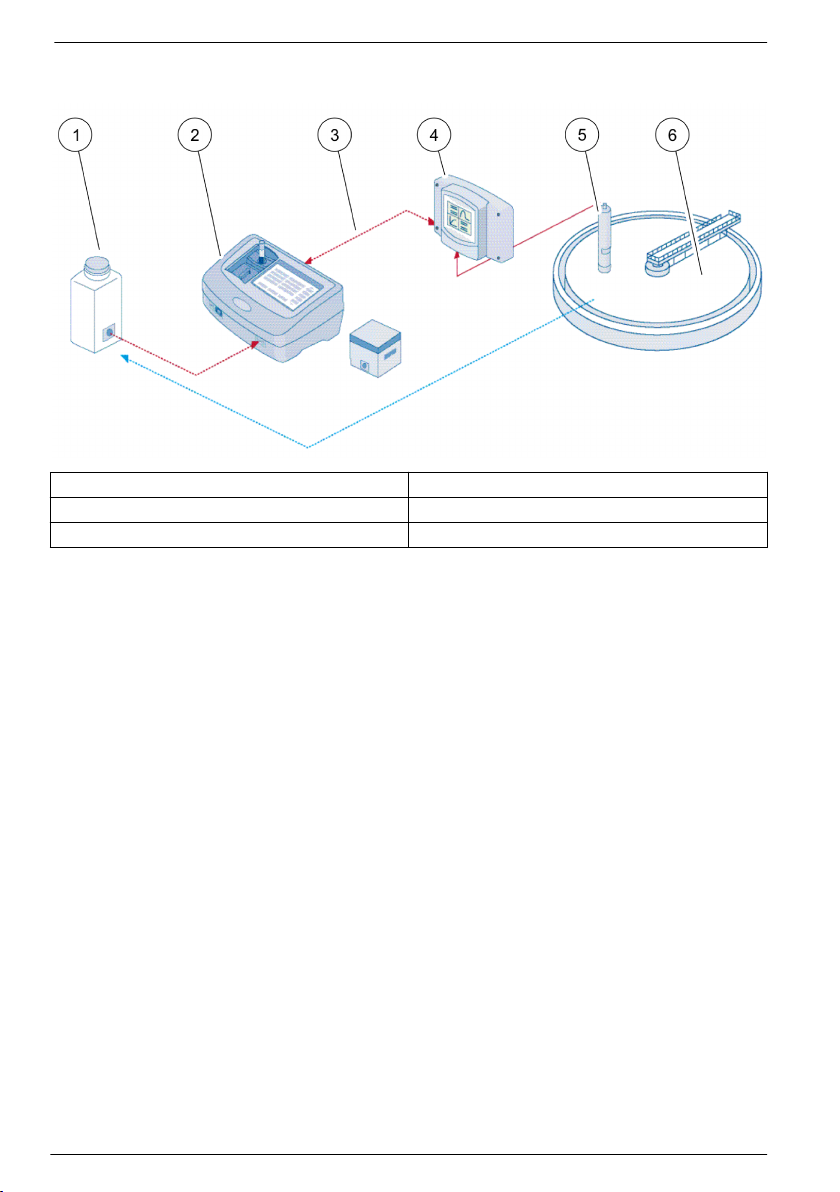
Figure 1 Communication between the process measurement equipment and the photometer
in the laboratory
1 Water probe drawn at the same time 4 sc controller
2 Photometer and barcode test 5 sc probe
3 Data transfer: SD memory card or LAN 6 Process basin
Introduction to matrix correction
There are various options available for sc probes to correct the probe value by means of laboratory
values (as a reference value).
This example uses the AN-ISE sc probe, for which the sample laboratory value can be entered as
either nitrate nitrogen (NO3-N) or ammonium nitrogen (NH4-N). This laboratory value corrects the
value measured by the probe. For precise information, please refer to the calibration/matrix
correction chapter of the AN-ISE sc user manual.
LINK2SC supports matrix correction 1 and 2 and makes an independent decision as to which of the
two correction types is to be used for the application. The comparison measurements should be
taken on different days and at different times in order to record a maximum number of changes in
concentration. The following table describes the two correction types in more detail.
4
English
Page 5

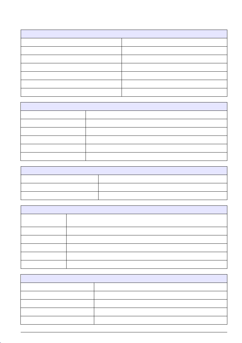
Table 1 AN-ISE sc correction types (extract from user manual)
LINK2SC Correction Application
CREATE JOB MATRIX1 MATRIX1 is the most commonly used correction type and is the
NEW MEASUREMENT MATRIX2 MATRIX2 correction is recommended for dynamic processes with a large
recommended first step. MATRIX1 performs a single-point matrix
correction for ammonium and/or nitrate; this is done either with or without
compensation electrode correction (potassium and/or chloride), though
"without" is sufficient in most cases. Compensation electrode correction is
only necessary if a higher level of accuracy is required. With a MATRIX1,
a sample must be taken when the correction is triggered and analyzed in
the laboratory. MATRIX1 is activated when the laboratory value is
entered.
fluctuation of nitrate/ammonium over at least half a decade2. With a
MATRIX2, a sample must be taken for both points (a high and a low
concentration) when the correction is triggered and analyzed in the
laboratory. MATRIX2 is activated when the laboratory value is entered.
Installation
LAN
Configure the photometer IP address on the sc1000 controller3. Also observe the instructions in the
user manuals for the photometer and the sc controller.
SD memory card
The sc controller has an SD memory card slot.
The SD memory card is used to:
• Save log files from all instruments.
• Update the sc controller software.
• Restore settings without network access.
• Perform the LINK2SC process.
The SD memory card must be inserted in a USB adapter in order to connect to the photometer.
Operation
Work sequence: CREATE JOB
1. Create the job file on the sc controller (refer to Work sequence: sc controller on page 7).
a. Select LINK2SC from the sc controller menu.
b. Select CREATE JOB from the LINK2SC menu.
c. Select the SENSOR NAME from the create job menu.
d. Select the PARAMETER of the job file from the sensor menu.
e. As soon as the parameter has been selected, take a comparison sample for the laboratory
measurement.
f. Use JOB->LAB to transfer the job file from the job status menu to the laboratory. (SD memory
card must be inserted in the sc controller if this is being used.)
2
Examples of half a decade: The concentrations of nitrate nitrogen shift between 1 and 5 mg/L
NO3-N and between 5 and 25 mg/L NO3-N. (Conc2 = (Conc1 × 10)/2)
3
Only valid for sc1000 controllers.
English 5
Page 6

2. Process the job with the photometer (refer to Work sequence: photometer on page 8). (If the
SD memory card is being used, it must be connected to the photometer via a USB adapter.)
a. Use the LINK2SC button on the toolbar to open the job list. Pending jobs are identified with
numbers in a yellow circle.
b. Select a job.
c. Select the parameter to be processed.
d. Analyze the comparison sample.
e. Assign the result to the job, if applicable.
f. Use SEND to adjust. (If the SD memory card is being used, it must be connected to the
photometer via a USB adapter.)
3. LAN4: When the default setting is active, the probe is automatically corrected with the laboratory
measurement data once the job has been returned.
Note: LINK2SC>CONFIGURE>AUTO JOB can be used to deactivate automatic correction. The probe must
then be corrected manually as per transfer via SD memory card.
or
SD memory card: The job must then be activated manually on the controller. Proceed as follows:
a. Insert the SD memory card in the sc controller.
b. Select LINK2SC from the sc controller menu.
c. Select JOBS FROM CARD from the LINK2SC menu. (Jobs are loaded into the sc controller.)
d. Select JOB LIST from the LINK2SC menu.
e. Select the corresponding job from the list.
f. Select ACTIVATE JOB. (The probe is corrected.)
Work sequence: NEW MEASUREMENT
1. In order for LINK2SC to be able to select the best correction type for the application in question
(refer to Introduction to matrix correction on page 4), each further sensor correction must be
performed via "NEW MEASUREMENT" and not via "CREATE JOB".
a. Select LINK2SC from the sc controller menu.
b. Select JOB LIST from the LINK2SC menu.
c. Select the corresponding job from the list.
d. Select NEW MEASUREMENT.
e. Select the PARAMETER for the new measurement.
f. Take a comparison sample for the laboratory measurement.
g. Use JOB->LAB to transfer the job file from the job status menu to the laboratory. (SD memory
card must be inserted in the sc controller if this is being used.)
2. Process the job with the photometer (refer to Work sequence: CREATE JOB on page 5 step 2).
3. LAN5: The probe is automatically corrected with the laboratory measurement data once the job
has been returned.
or
SD memory card: The job must then be activated manually on the controller (refer to Work
sequence: CREATE JOB on page 5 step 3).
4
Only valid for sc1000 controllers.
5
Only valid for sc1000 controllers.
6 English
Page 7
Work sequence: sc controller
Menu structure based on sc1000 controller; the menu structure for the sc200 may differ slightly.
MENU
SENSOR STATUS Refer to sc controller user manual.
SENSOR SETUP Refer to sc controller user manual.
SYSTEM SETUP Refer to sc controller user manual.
SERVICE Refer to sc controller user manual.
LINK2SC Select to call up the LINK2SC menu.
CREATE JOB Create a new job.
SENSOR NAME (in this case: ANISE SC) Select the required probe (e.g. AN-ISE SC).
Submenu: parameter selection
Parameter 1 Here: NH4-N + NO3-N
Parameter 2 Here: NH4-N
Parameter 3 Here: NO3-N
Parameter 4 Here: NH4-N + K
Parameter 5 Here: NO3-N + Cl
Parameter 6 Here: NH4-N + K + NO3-N + Cl
Once the parameter is selected, a request for a sample is generated
LINK2SC Job displayed in job status menu with:
SAMPLE NUMBER Sample number
JOB->LAB Select and confirm
Confirmation is displayed once the job has been sent.
JOBS FROM CARD Only active when processed jobs from the laboratory are present on the SD memory
JOB LIST Job list containing all jobs.
JOB 1 Job with number and date.
ANISE SC Probe information
JOB INFORMATION Job number
NEW MEASUREMENT Trigger new measurement for MATRIX2 correction.
Submenu: parameter selection
JOB->LAB Send job to laboratory.
ACTIVATE JOB Activate job entered via SD memory card.
ERASE JOB Delete the job from the list.
JOB N Job with number and date.
CONFIGURE LINK2SC configuration
card.
English 7
Page 8
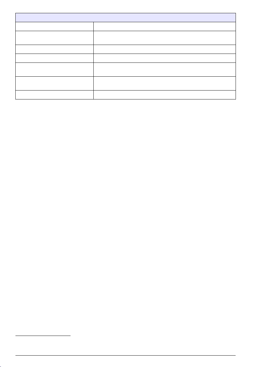
Submenu: parameter selection
TRANSMISSION
IP ADDRESS IP address or network name for the instrument to which the job is to be
JOB ID MIN Lower limit for job number range.
JOB ID MAX Upper limit for job number range.
AUTO JOB Select whether a job returned by the photometer is activated
SENSOR NAME (in this case: AN-ISE) If this is selected, the job is activated automatically. Uncheck to
PROGNOSYS Refer to sc controller user manual.
6
Transfer type selection: SD memory card or network.
sent.
automatically.
deactivate.
Work sequence: photometer
1. Once the job has been transferred via LAN or SD memory card to the photometer, press the
LINK2SC button on the toolbar.
A LINK2SC job list is displayed.
2. Select the job to be processed and use SELECT to open it.
The job details are then displayed: job ID, date, time, parameter, sensor measurement value and
proposed test.
3. Use one of the instructions that follow to select the parameter and examine the test.
a. To examine with a recommended barcode test, insert the coded vial.
b. To examine with a recommended non-barcode test, push MEASURE and start the
measurement.
c. To examine with a non-recommended test, select OPTION>SELECT PROGRAM. Select a
program and push MEASURE to start the measurement.
4. Select ASSIGN RESULT TO JOB, if applicable.
5. Use the options in JOB DETAILS to edit and delete the measurement result or do the result
assignment from the data log.
6. Select SEND to send a single parameter to the controller.
7. Select JOB LIST to show the list.
8. Select SEND to send a completed job to the controller.
a. LAN7: The probe is automatically corrected with the laboratory measurement data once the
job has been returned.
Note: Once the correction has been implemented successfully, confirmation (job with green tick) is sent
back to the photometer, where it can be archived. If an implausible measurement value means that the
correction cannot be made, the job is returned with a red cross.
Note: If the network connection is interrupted, an error message is output. The job can also be saved on a
connected SD memory card and transferred to the controller that way.
b. SD memory card: If the SD memory card is being used, it must be connected to the
photometer via a USB adapter. The job must then be manually activated on the controller.
The JOB LIST button goes back to the list to access the Main Menu.
9. Use OPTIONS to access a submenu for job management. HISTORY accesses completed
archived jobs; DELETE JOB moves jobs to the archive.
6
Only valid for sc1000 controllers.
7
Only valid for sc1000 controllers.
8 English
Page 9
Table des matières
Caractéristiques à la page 9 Installation à la page 11
Présentation du produit à la page 9 Fonctionnement à la page 11
Caractéristiques
Les caractéristiques techniques peuvent être modifiées sans préavis.
Produit Version du logiciel
Transmetteur sc1000 V 1.3
Transmetteur sc200 V 1.0
DR 3900 V 1.0
AN-ISE sc V 1.03
Présentation du produit
La fonction logicielle LINK2SC optimise l'interaction entre l'instrument de mesure de processus et le
photomètre dans le laboratoire. Elle permet une correction de mesure directe du capteur scen ligne
via un photomètre utilisé dans des conditions de laboratoire (voir la Introduction à la correction de
matrice à la page 10). LINK2SC permet également d'effectuer des mesures de contrôle de
laboratoire. Les mesures sont transférées du capteursc au photomètre, où elles sont archivées avec
les données de référence photométriques.
Une ou plusieurs mesures en ligne sont utilisées pour créer une tâche sur le transmetteursc, laquelle
est transférée au photomètre via une connexion réseau local ou via une carte mémoire SD et un
adaptateur USB. Une tâche est un fichier XML qui contient les mesures ainsi que des informations
supplémentaires sur le capteur et le transmetteur.
L'échantillon d'eau prélevé simultanément est analysé dans le laboratoire selon les mêmes
paramètres.
Dans le photomètre, la valeur photométrique mesurée est assignée à la valeur du capteur dans la
tâche. Si la tâche est renvoyée au transmetteursc, le capteur est corrigé automatiquement
Le transfert des données s'effectue via une carte mémoire SD ou le réseau local (LAN)1.
1
Valable uniquement pour les transmetteurs sc1000.
Français 9
Page 10

Figure 1 Communication entre l'instrument de mesure de processus et le photomètre au
laboratoire
1 Echantillon d'eau prélevé simultanément 4 Transmetteur sc
2 Photomètre et test de code à barres 5 capteursc
3 Transfert des données : carte mémoire SD ou LAN 6 Bac de processus
Introduction à la correction de matrice
Diverses options de capteursc sont disponibles pour corriger la valeur du capteur au moyen de
valeurs de laboratoire (utilisées comme valeurs de référence).
Dans cet exemple est utilisé un capteur scAN-ISE, pour lequel la valeur de laboratoire
d'échantillonnage peut être saisie sous la forme d'azote nitrique (NO3-N) ou ammoniacal (NH4-N).
Cette valeur de laboratoire corrige la valeur mesurée par le capteur. Pour plus d'informations,
reportez-vous au chapitre sur l'étalonnage/la correction de matrice du manuel d'utilisation du capteur
scAN-ISE.
LINK2SC prend en charge la correction de matrice 1 et 2 et décide en toute indépendance lequel de
ces deux types de correction sera utilisé pour l'application. Les mesures comparatives doivent être
effectuées à des jours et des heures différents, afin d'enregistrer un maximum de modifications dans
la concentration. Le tableau ci-dessous décrit plus précisément les deux types de correction.
10
Français
Page 11

Tableau 1 Types de correction scAN-ISE(extrait du manuel d'utilisation)
LINK2SC Correction Application
CREER
TACHE
NOUV
MESURE
MATRICE 1 MATRICE 1 correspond au type de correction le plus fréquemment utilisé ; c'est
la première étape recommandée. MATRICE 1 effectue une correction de
matrice sur un seul point pour l'azote nitrique et/ou ammoniacal. Cette opération
est réalisée avec ou sans correction de l'électrode de compensation (potassium
et/ou chlorure), bien que la non-correction suffise dans la plupart des cas. La
correction de l'électrode de compensation est nécessaire uniquement si un
degré de précision supérieur est requis. Avec une correction MATRICE 1, un
échantillon doit être prélevé lorsque la correction est déclenchée, puis analysé
en laboratoire. MATRICE 1 est activé lorsque la valeur de laboratoire est saisie.
MATRICE 2 La correction MATRICE 2 est recommandée pour les processus dynamiques
présentant une grande variaton d'azote nitrique/ammoniacal sur au moins une
demi-décade2. Avec une correction MATRICE 2, un échantillon doit être prélevé
pour les deux points (concentration faible et élevée) lorsque la correction est
déclenchée, puis analysé en laboratoire. MATRICE 2 est activé lorsque la valeur
de laboratoire est saisie.
Installation
LAN
Configurez l'adresse IP du photomètre sur le transmetteursc10003. Respectez les instructions des
manuels d'utilisation du photomètre et du transmetteursc.
Carte mémoire SD
Le transmetteur sc dispose d'une fente pour carte mémoire SD.
La carte mémoire SD permet d'effectuer les tâches suivantes :
• Enregistrement des fichiers journaux de tous les instruments.
• Mise à jour du logiciel du transmetteur sc.
• Restauration des paramètres sans accès au réseau.
• Exécution du processus LINK2SC.
La carte mémoire SD doit être insérée dans un adaptateur USB pour être connectée au photomètre.
Fonctionnement
Séquence de travail : CREER TACHE
1. Créez le fichier de tâche sur le transmetteur SC (voir Transmetteur sc à la page 13).
a. Sélectionnez LINK2SC dans le menu du transmetteursc.
b. Sélectionnez CREER TACHE dans le menu LINK2SC.
c. Sélectionnez leNOM DU CAPTEUR dans le menu CREER TACHE.
d. Sélecetionnez le PARAMETRE du fichier de tâche dans le menu du capteur.
e. Dès que le paramètre a été sélectionné, prélevez un échantillon de comparaison pour la
mesure de laboratoire.
f. Utilisez JOB->LAB pour transférer le fichier de tâche du menu d'état vers le laboratoire. (La
carte mémoire SD doit être insérée dans le transmetteursc si vous l'utilisez.)
2
Exemples sur cinq ans : les concentrations en azote nitrique sont passées de 1 à 5 mg/L NO3-N
et de 5 à 25 mg/L NO3-N. (Conc2 = (Conc1 × 10)/2)
3
Valable uniquement pour les transmetteurs sc1000.
Français 11
Page 12

2. Traitez la tâche avec le photomètre (voir la Séquence de travail : photomètre à la page 14). Si
vous utilisez la carte mémoire SD, vous devez la connecter au photomètre via un adaptateur
USB.)
a. Utilisez le bouton LINK2SC de la barre d'outils pour ouvrir la liste des tâches. Les tâches en
attente sont identifiées par des numéros dans un cercle jaune.
b. Sélectionnez une tâche.
c. Sélectionnez le paramètre à traiter.
d. Analysez l'échantillon de comparaison.
e. Affectez le résultat à la tâche, si nécessaire.
f. Utilisez SEND pour procéder à l'ajustement. Si vous utilisez la carte mémoire SD, vous devez
la connecter au photomètre via un adaptateur USB.)
3. LAN4 : lorsque le réglage par défaut est activé, le capteur est corrigé automatiquement au moyen
des mesures de laboratoire aussitôt la tâche renvoyée.
Remarque : LINK2SC>CONFIGURE>AUTO JOB permet de désactiver la correction automatique. Le capteur
doit alors être corrigé manuellement, conformément au transfert via la carte mémoire SD.
ou
Carte mémoire SD : la tâche doit être activée manuellement sur le transmetteur. Procédez
comme suit :
a. Insérez la carte mémoire SD dans le tansmetteursc.
b. Sélectionnez LINK2SC dans le menu du transmetteursc.
c. Sélectionnez TACHES CARTE dans le menu LINK2SC. (Les tâches sont chargées dans le
transmetteur sc.)
d. Sélectionnez LISTE TACHE dans le menu LINK2SC.
e. Sélectionnez la tâche correspondante dans la liste.
f. Sélectionnez ACTIVER TACHE. (Le capteur est corrigé.)
Séquence de travail : NOUV MESURE
1. Afin que LINK2SC puisse sélectionner le meilleur type de correction pour l'application concernée
(voir Introduction à la correction de matrice à la page 10), toute autre correction de capteur doit
se faire avec l'option « NOUV MESURE » et non pas « CREER TACHE ».
a. Sélectionnez LINK2SC dans le menu du transmetteursc.
b. Sélectionnez LISTE TACHE dans le menu LINK2SC.
c. Sélectionnez la tâche correspondante dans la liste.
d. Sélectionnez NOUV MESURE.
e. Sélectionnez le PARAMETRE pour la nouvelle mesure.
f. Prélevez un échantillon de comparaison pour la mesure de laboratoire.
g. Utilisez JOB->LAB pour transférer le fichier de tâche du menu d'état vers le laboratoire. (La
carte mémoire SD doit être insérée dans le transmetteursc si vous l'utilisez.)
2. Traitez la tâche avec le photomètre (voir Séquence de travail : CREER TACHE à la page 11
étape 2).
3. LAN5 : le capteur est corrigé automatiquement avec les mesures de laboratoire aussitôt la tâche
renvoyée.
ou
Carte de mémoire SD : la tâche doit être activée manuellement sur le transmetteur (voir
Séquence de travail : CREER TACHE à la page 11 étape 3).
4
Valable uniquement pour les transmetteurs sc1000.
5
Valable uniquement pour les transmetteurs sc1000.
12 Français
Page 13

Transmetteur sc
Structure de menu basée sur le transmetteur sc1000 ; la structure de menu du sc200 peut différer
légèrement.
Touche
ETAT CAPTEUR Voir le manuel de l'utilisateur du transmetteur SC.
CONFIG. CAPTEUR Voir le manuel de l'utilisateur du transmetteur SC.
CONFIG. SYSTEME Voir le manuel de l'utilisateur du transmetteur SC.
SERVICE Voir le manuel de l'utilisateur du transmetteur SC.
LINK2SC Affiche le menu LINK2SC.
CREER TACHE Crée une nouvelle tâche.
NOM CAPTEUR (dans ce cas : ANISESC) Permet de sélectionner le capteur requis (p. ex., AN-ISE SC).
Sous-menu : sélection des paramètres
Paramètre 1 Ici : NH4-N + NO3-N
Paramètre 2 Ici : NH4-N
Paramètre 3 Ici : NO3-N
Paramètre 4 Ici : NH4-N + K
Paramètre 5 Ici : NO3-N + Cl
Paramètre 6 Ici : NH4-N+ K + NO3-N + Cl
Une fois le paramètre sélectionné, une demande d'échantillonnage est générée.
LINK2SC Tâche affichée dans le menu d'état des tâches avec :
N° ECHANTILLON Numéro de l'échantillon
JOB->LAB Sélection et confirmation
Une confirmation s'affiche une fois la tâche envoyée.
TACHES CARTE Option active uniquement lorsque des tâches traitées depuis le laboratoire sont présentes
LISTE DE TACHES Liste contenant toutes les tâches.
TACHE 1 Tâche avec numéro et date.
ANISE SC Informations sur la sonde
INFO TACHE Numéro de la tâche
NOUV MESURE Déclenche une nouvelle mesure pour la correction MATRICE 2.
Sous-menu : sélection des paramètres
JOB->LAB Envoie la tâche au laboratoire.
ACTIVER TACHE Active la tâche entrée via la carte mémoire SD.
EFFACER TACHE Supprime la tâche de la liste.
TACHE N Tâche avec numéro et date.
dans la carte mémoire SD.
Français 13
Page 14

Sous-menu : sélection des paramètres
CONFIGURE (Configurer) Configuration LINK2SC
TRANSMISSION
ADRESSE IP Adresse IP ou nom du réseau pour l'instrument vers lequel la tâche doit
IDENT. MINIMALE TACHE Limite inférieure de la plage de numéros de tâche.
IDENT. MAXIMALE TACHE Limite supérieure de la plage de numéros de tâche.
TACHE AUTO Permet de sélectionner si une tâche renvoyée par le photomètre doit être
NOM CAPTEUR (dans ce cas : ANISE)
PROGNOSYS Voir le manuel de l'utilisateur du transmetteur SC.
6
Sélection du type de transfert : carte mémoire SD ou réseau.
être envoyée.
activée automatiquement.
Si cette option est sélectionnée, la tâche est activée automatiquement.
Désélectionnez cette option pour la désactiver.
Séquence de travail : photomètre
1. Une fois la tâche transférée au photomètre via le réseau LAN ou la carte mémoire SD, appuyez
sur le bouton LINK2SC de la barre d'outils.
La liste des tâches LINK2SC s'affiche.
2. Sélectionnez la tâche à traiter et utilisez SELECT pour l'ouvrir.
Les détails de la tâche (numéro de la tâche, date, heure, paramètre, valeur de mesure du capteur
et test proposé) apparaissent alors.
3. Appliquez l'une des instructions suivantes pour sélectionner le paramètre et vérifier le test.
a. Pour effectuer le test recommandé avec un code-barre, insérez la fiole codée.
b. Pour effectuer le test recommandé sans code-barre, appuyez sur MEASURE et effectuez la
mesure.
c. Pour effectuer un test non recommandé, sélectionnez OPTION>SELECT PROGRAM.
Sélectionnez un programme et appuyez sur MEASURE pour effectuer la mesure.
4. Sélectionnez ASSIGN RESULT TO JOB, si nécessaire.
5. Utilisez les options de la section JOB DETAILS pour modifier ou supprimer les résultats de la
mesure ou affecter le résultat depuis le journal de données.
6. Sélectionnez SEND pour envoyer un paramètre unique au transmetteur.
7. Sélectionnez LISTE DE TACHES pour afficher la liste.
8. Sélectionnez SEND pour envoyer une tâche terminée au transmetteur.
a. LAN7 : le capteur est corrigé automatiquement avec les mesures de laboratoire aussitôt la
tâche renvoyée.
Remarque : Une fois la correction implémentée, la confirmation (tâche avec coche verte) est renvoyée au
photomètre, où elle peut être archivée. Si une mesure non plausible empêche l'exécution de la correction,
la tâche est renvoyée accompagnée d'une croix rouge.
Remarque : Si la connexion au réseau est interrompue, un message d'erreur est renvoyé. La tâche peut
aussi être enregistrée sur une carte mémoire SD connectée et transférée au transmetteur de cette
manière.
b. Carte mémoire SD : si vous utilisez la carte mémoire SD, vous devez la connecter au
photomètre via un adaptateur USB. La tâche doit ensuite être activée manuellement sur le
contrôleur. Le bouton LISTE DE TACHES revient à la liste pour accéder au menu principal.
9. Utilisez OPTIONS pour accéder au sous-menu de gestion des tâches. HISTORY donne accès
aux tâches terminées et archivées ; DELETE JOB déplace les tâches vers l'archive.
6
Valable uniquement pour les transmetteurs sc1000.
7
Valable uniquement pour les transmetteurs sc1000.
14 Français
Page 15

Tabla de contenidos
Especificaciones en la página 15 Instalación en la página 17
Descripción general del producto en la página 15 Funcionamiento en la página 17
Especificaciones
Las especificaciones están sujetas a cambios sin previo aviso.
Producto Versión de software
Controlador SC1000 V 1.3
Controlador SC200 V 1.0
DR 3900 V 1.0
AN-ISE SC V 1.03
Descripción general del producto
La función de software Link2sc permite una óptima interacción entre el equipo de medición de
proceso y el fotómetro en el laboratorio. Permite una corrección de medición directa de la sonda SC
en continuo a través de un fotómetro de laboratorio (consulte Introducción a la corrección de matriz
en la página 16). Link2sc además permite una medición de control de laboratorio. Los datos de
medición se transfieren desde la sonda SC hasta el fotómetro, donde se archivan junto con los datos
fotométricos de referencia.
Se usan uno o más valores de medición en continuo para crear una tarea en el controlador SC; esta
tarea se transfiere al fotómetro a través de una conexión de red local o a través de una tarjeta de
memoria SD y un adaptador USB. Una tarea es un archivo XML que contiene valores de medición e
información adicional del controlador y la sonda.
La medición de la muestra se obtiene al mismo tiempo que ésta se analiza en el laboratorio según
los mismos parámetros.
En el fotómetro, el valor fotométrico medido se asigna al valor de la sonda en la tarea. Si la tarea
luego se envía de regreso al controlador SC, la sonda se corrige automáticamente.
La transferencia de datos se realiza a través de la tarjeta de memoria SD o de la red local (LAN)1.
1
Válido solo para controladores SC1000
Español 15
Page 16

Figura 1 Comunicación entre el equipo de medición de proceso y el fotómetro en el
laboratorio
1 La muestra de agua se obtiene al mismo tiempo 4 Controlador SC
2 Fotómetro y test de código de barras 5 sonda SC
3 Transferencia de datos: tarjeta de memoria SD o
LAN
6 Tanque del proceso
Introducción a la corrección de matriz
Existen distintas opciones disponibles para que las sondas SC corrijan el valor de sonda mediante
valores de laboratorio (como valor de referencia).
Este ejemplo usa una sonda AN-ISE SC, para la cual se puede ingresar el valor de muestra de
laboratorio como nitrógeno en nitrato (NO3-N) o nitrógeno amoniacal (NH4-N). Este valor de
laboratorio corrige el valor medido por la sonda. Para obtener información más detallada, consulte el
capítulo de corrección de calibración/matriz del manual del usuario de AN-ISE SC.
Link2sc es compatible con la corrección de matriz 1 y 2 y toma una decisión independiente de cuál
de los dos tipos de corrección se usará para la aplicación. Las mediciones de comparación deberían
tomarse en diferentes días y en horas distintas para registrar los mayores cambios en la
concentración. La siguiente tabla describe los dos tipos de corrección de forma más detallada.
16
Español
Page 17

Tabla 1 Tipos de corrección AN-ISE SC (extraído del manual del usuario)
Link2sc Correction
CREAR TAREA MATRIZ 1 MATRIZ 1 es el tipo de corrección más utilizado y se recomienda como
NUEVA
MEDICION
(Corrección)
MATRIZ 2 La corrección MATRIX2 (MATRIZ 2) está recomendada para procesos
Aplicación
primer paso. MATRIZ 1 realiza una corrección de matriz en un punto
para amonio y nitrato; dicha corrección se realiza con o sin una
corrección de electrodo de compensación (potasio o cloruro), aunque
"sin" es suficiente en la mayoría de los casos. La corrección de
electrodo de compensación solo es necesaria cuando se requiere un
nivel mayor de precisión. Con la corrección MATRIZ 1, se debe tomar
una muestra cuando se inicie la corrección, y se debe analizar en el
laboratorio. MATRIZ 1 se activa al introducir el valor de laboratorio.
dinámicos con una gran fluctuación de nitrato/amonio de al menos
media década2. Con la corrección MATRIZ 2, se deben tomar
muestras de ambos puntos (una concentración alta y una baja) cuando
se inicie la corrección y deben ser analizadas en el laboratorio.
MATRIZ 2 se activa al introducir los valores de laboratorio.
Instalación
LAN
Configure la dirección IP del fotómetro en el controlador SC10003. También considere las
instrucciones en los manuales del usuario del fotómetro y el controlador SC.
Tarjeta de memoria SD
El controlador SC tiene una ranura para tarjeta de memoria SD.
La tarjeta de memoria SD se usa para:
• Guardar archivos de registro provenientes de todos los instrumentos.
• Actualizar el software del controlador SC.
• Restaurar las configuraciones sin acceso a la red.
• Realizar el proceso Link2sc.
La tarjeta de memoria SD debe insertarse en un adaptador USB para conectarla al fotómetro.
Funcionamiento
Secuencia de trabajo: CREAR TAREA
1. Crear el archivo de tarea en el controlador SC (consulte Secuencia de trabajo: controlador SC
en la página 19).
a. Seleccione Link2sc desde el menú del controlador SC.
b. Seleccione CREAR TAREA desde el menú Link2sc.
c. Seleccione el SENSOR NAME (NOMBRE DE SENSOR) desde el menú CREAR TAREA.
d. Seleccione el PARAMETER (PARÁMETRO) del archivo de tarea desde el menú sensor.
e. Tan pronto se haya seleccionado el parámetro, tome una muestra de comparación para la
medición en laboratorio.
2
Ejemplos de una media década: las concentraciones de nitrógeno en nitrato cambian entre 1 y
5 mg/l de NO3-N o entre 5 y 25 mg/l NO3-N. (Conc2 = (Conc1 × 10)/2)
3
Válido solo para controladores SC1000
Español 17
Page 18

f. Utilice JOB->LAB (TAREA->LABORATORIO) para transferir el archivo de tarea del menú de
estado de la tarea al laboratorio. (La tarjeta de memoria SD se debe insertar en el controlador
SC si se está utilizando.)
2. Procese la tarea con el fotómetro (consulte Secuencia de trabajo: fotómetro en la página 20).
(Si se está usando la tarjeta de memoria SD, debe estar conectada al fotómetro a través de un
adaptador USB.)
a. Use el botón Link2sc de la barra de herramientas para abrir la lista de tareas. Las tareas
pendientes están identificadas con números dentro de un círculo amarillo.
b. Seleccione una tarea.
c. Seleccione el parámetro que desea procesar.
d. Analice la muestra de comparación.
e. Asigne el resultado a la tarea, si corresponde.
f. Utilice SEND (ENVIAR) para ajustar. (Si se está usando la tarjeta de memoria SD, debe estar
conectada al fotómetro a través de un adaptador USB.)
3. LAN4: cuando la configuración predeterminada está activada, la sonda corrige automáticamente
los datos de medición de laboratorio una vez que se retorna la tarea.
Nota: Puede utilizar Link2sc>CONFIGURE>AUTO JOB (Link2sc>CONFIGURAR>TAREA AUTO) para
desactivar la corrección automática. La sonda entonces debe corregirse manualmente de acuerdo con la
transferencia a través de la tarjeta de memoria SD.
o
Tarjeta de memoria SD: la tarea se debe activar manualmente en el controlador. Proceda en la
forma indicada a continuación:
a. Inserte la tarjeta de memoria SD en el controlador SC.
b. Seleccione Link2sc desde el menú del controlador SC.
c. Seleccione TAREAS DESDE TARJETA desde el menú Link2sc. (Las tareas se cargan en el
controlador SC.)
d. Seleccione LISTA TAREAS desde el menú Link2sc.
e. Seleccione la tarea correspondiente desde la lista.
f. Seleccione ACTIVAR TAREA. (La sonda se corrige.)
Secuencia de trabajo: NUEVA MEDICION
1. Para que Link2sc pueda seleccionar el mejor tipo de corrección para la aplicación en cuestión
(consulte Introducción a la corrección de matriz en la página 16), cada corrección adicional del
sensor debe realizarse mediante "NEW MEASUREMENT" (NUEVA MEDICIÓN) y no mediante
"CREATE JOB" (CREAR TAREA).
a. Seleccione Link2sc desde el menú del controlador SC.
b. Seleccione LISTA TAREAS desde el menú Link2sc.
c. Seleccione la tarea correspondiente desde la lista.
d. Seleccione NUEVA MEDICION.
e. Seleccione el PARAMETER (PARÁMETRO) para la nueva medición.
f. Tome una muestra de comparación para la medición en laboratorio.
g. Utilice JOB->LAB (TAREA->LABORATORIO) para transferir el archivo de tarea del menú de
estado de la tarea al laboratorio. (La tarjeta de memoria SD se debe insertar en el controlador
SC si se está utilizando.)
2. Procese la tarea con el fotómetro (consulte Secuencia de trabajo: CREAR TAREA
en la página 17 paso 2).
3. LAN5: la sonda se corrige automáticamente con los datos de medición de laboratorio una vez
que se retornó la tarea.
4
Válido solo para controladores SC1000
5
Válido solo para controladores SC1000
18 Español
Page 19

o
Tarjeta de memoria SD: la tarea debe ser activada manualmente en el controlador (consulte
Secuencia de trabajo: CREAR TAREA en la página 17 paso 3).
Secuencia de trabajo: controlador SC
Estructura de menús basada en controlador SC1000; la estructura de menú para el SC200 puede
diferir levemente.
Tecla
SENSOR STATUS (ESTADO DEL SENSOR) Consulte el manual del usuario del controlador SC.
SENSOR SETUP (CONFIG SENSOR) Consulte el manual del usuario del controlador SC.
CONFIG SISTEMA Consulte el manual del usuario del controlador SC.
MANTENIM Consulte el manual del usuario del controlador SC.
Link2sc Seleccionar visualización de menú Link2sc.
CREAR TAREA Crear una tarea nueva.
SENSOR NAME (NOMBRE DE SENSOR)(en este
caso: ANISE SC)
Submenú: selección de parámetro
Parámetro 1 Aquí: NH4-N + NO3-N
Parámetro 2 Aquí: NH4-N
Parameter 3 (Parámetro 3) Aquí: NO3-N
Parameter 4 (Parámetro 4) Aquí: NH4-N + K
Parameter 5 (Parámetro 5) Aquí: NO3-N + C1
Parameter 6 (Parámetro 6) Aquí: NH4-N+ K + NO3-N +C1
Seleccionar la sonda requerida (por ejemplo, AN-ISE SC).
Una vez que se selecciona el parámetro, se requiere una muestra
Link2sc La tarea aparece en el menú de estado de la tarea con:
NUMERO MUESTRA Número de muestra
JOB->LAB (TAREA->LABORATORIO) Seleccionar y confirmar
Aparece la confirmación una vez que se ha enviado la tarea.
TAREAS DE TARJETA Solo se activa cuando las tareas procesadas en el laboratorio están presentes en la
LISTA DE TAREAS Lista de tareas que contiene todas las tareas.
JOB 1 (TAREA 1) Tarea con número y fecha.
ANISE SC Información de la sonda
INFO TAREA Número de tarea
NUEVA MEDICION Iniciar nueva medición para corrección MATRIZ 2.
tarjeta de memoria SD.
Español 19
Page 20

Submenú: selección de parámetro
JOB->LAB (TAREA->LABORATORIO) Enviar tarea al laboratorio.
ACTIVAR TAREA Activar tarea introducida a través de la tarjeta de memoria SD.
BORRAR TAREA Eliminar la tarea de la lista.
JOB N (N° TAREA) Trabajo con número y fecha .
CONFIGURE (Configurar) Configuración de Link2sc
TRANSMISION
DIRECCIÓN IP Dirección IP o nombre de red para el instrumento al que se envía la
MÍN. ID DE TAREA Límite inferior para el rango de número de la tarea.
MÁX. ID DE TAREA Límite superior para el rango de número de la tarea.
AUTO JOB (TAREA AUTO) Seleccione si la tarea retornada por el fotómetro se activará
SENSOR NAME (NOMBRE DE
SENSOR) (en este caso: AN-ISE)
PROGNOSYS Consulte el manual del usuario del controlador SC.
6
Selección de tipo de transferencia: tarjeta de memoria SD o red.
tarea.
automáticamente.
Si esto se selecciona, la tarea se activa automáticamente.
Desmarque para desactivar.
Secuencia de trabajo: fotómetro
1. Una vez que la tarea se ha transferido al fotómetro a través de la LAN o la tarjeta de memoria
SD, presione el botón Link2sc en la barra de herramientas.
Aparece una lista de tareas Link2sc.
2. Seleccione la tarea que va a ser procesada y use SELECT (SELECCIONAR) para abrirla.
A continuación aparecen los detalles de la tarea: ID de tarea, fecha, hora, parámetro, valor de
medición del sensor y método de análisis propuesto.
3. Utilice una de las siguientes instrucciones para seleccionar el parámetro y realizar el test.
a. Para realizar el test con un reactivo recomendado de código de barras, inserte la cubeta
codificada.
b. Para realizar el test con un reactivo recomendado sin código de barras, pulse MEASURE
(MEDIR) y comience la medición.
c. Para realizar el test con un reactivo no recomendado, seleccione OPTION>SELECT
PROGRAM (OPCIÓN>SELECCIONAR PROGRAMA). Seleccione un programa y pulse
MEASURE (MEDIR) para comenzar la medición.
4. Seleccione ASSIGN RESULT TO JOB (ASIGNAR RESULTADO A UNA TAREA), si
corresponde.
5. Utilice las opciones de JOB DETAILS (DETALLES DE LA TAREA) para editar y eliminar el
resultado de medición o realizar la asignación del resultado desde el registro de datos.
6. Seleccione SEND (ENVIAR) para enviar un parámetro único al controlador.
7. Seleccione JOB LIST (LISTA TAREAS) para mostrar la lista.
6
Válido solo para controladores SC1000
20 Español
Page 21

8. Seleccione SEND (ENVIAR) para enviar una tarea completada al controlador.
a. LAN7: la sonda se corrige automáticamente con los datos de medición de laboratorio una vez
que se retornó la tarea.
Nota: Una vez que la corrección se ha implementado con éxito, se envía una confirmación (tarea con una
marca verde) de regreso al fotómetro, donde se puede archivar. Si un valor de medición incorrecto implica
que la corrección no se puede realizar, la tarea se retorna con una marca de cruz roja.
Nota: Si se interrumpe la conexión de red, aparecerá un mensaje de error. La tarea también se puede
guardar en una tarjeta de memoria SD y transferir al controlador por ese medio.
b. Tarjeta de memoria SD: si se está usando la tarjeta de memoria SD, debe estar conectada al
fotómetro a través de un adaptador USB. A continuación, la tarea debe activarse
manualmente en el controlador. El botón de JOB LIST (LISTA TAREAS) vuelve a la lista para
acceder al menú principal.
9. Utilice OPTIONS (OPCIONES) para acceder a un submenú para la gestión de tareas. HISTORY
(HISTORIAL) accede a las tareas archivadas completadas; DELETE JOB (ELIMINAR TAREA)
mueve las tareas al archivo.
7
Válido solo para controladores SC1000
Español 21
Page 22
Índice
Especificações na página 22 Instalação na página 24
Visão geral do produto na página 22 Operação na página 24
Especificações
As especificações estão sujeitas a alterações sem aviso prévio.
Produto Versão do software
Controlador sc1000 V 1.3
Controlador sc200 V 1.0
DR 3900 V 1.0
AN-ISE sc V 1.03
Visão geral do produto
A função software LINK2SC proporciona uma interação ideal entre o equipamento de medição de
processos e o fotômetro no laboratório. A função viabiliza a correção direta de medições da sonda
scon-line via um fotômetro que opera sob condições de laboratório (consulte a Introdução à correção
de matrizes na página 23). O LINK2SC permite também a medição de controles de laboratório. Os
dados da medição são transferidos da sondasc para o fotômetro, onde são então arquivados
juntamente com os dados fotométricos de referência.
Um ou mais valores de medição on-line são usados para criar uma tarefa no controladorsc; esta
tarefa é transferida para o fotômetro por meio de uma conexão de rede local ou de um cartão de
memória SD e de um adaptador USB. Uma tarefa é um arquivo XML contendo valores de medição e
informações adicionais do controlador e da sonda.
A sonda está imersa ao mesmo tempo que a água é analisada no laboratório de acordo com os
mesmos parâmetros.
No fotômetro, o valor fotométrico medido é atribuído ao valor da sonda na tarefa. Se a tarefa for
devolvida ao controladorsc, a sonda será corrigida automaticamente.
A transferência de dados é feita por cartão de memória SD ou rede local (LAN)1.
1
Válido apenas para controladores sc1000.
22 Português
Page 23

Figura 1 Comunicação entre o equipamento de medição de processos e o fotômetro no
laboratório
1 Coleta de água simultânea 4 Controlador sc
2 Teste de código de barras e fotômetro 5 Sondasc
3 Transferência de dados: cartão de memória SD ou
LAN
6 Tanque de tratamento
Introdução à correção de matrizes
Há várias opções de sondas scdisponíveis que são usadas para corrigir o valor da sonda por meio
de valores de laboratório (na forma de um valor de referência).
Este exemplo utiliza a sonda AN-ISE, na qual o valor laboratorial da amostra pode ser inserido como
azoto nítrico (NO3-N) ou nitrogênio amoniacal (NH4-N). Esse valor laboratorial corrige o valor medido
pela sonda. Para obter informações precisas, consulte o capítulo sobre correção de
calibração/matriz do manual do usuário do AN-ISEsc.
O LINK2SC oferece suporte a correções de matriz 1 e 2 e deixa a critério do usuário a decisão sobre
qual dos dois tipos de correção deverá ser usado na aplicação. As medições comparativas devem
ser executadas em dias e horários diferentes de modo a registrar um número máximo de alterações
na concentração. A tabela a seguir descreve mais detalhadamente os dois tipos de correção.
Português
23
Page 24

Tabela 1 Tipos de correção do AN-ISEsc(trecho do manual do usuário)
LINK2SC Correção Aplicativo
CRIAR ENTRADA MATRIZ 1 MATRIZ 1 é o tipo de correção usado com mais frequência, além de ser a
NOVA AMOSTRA MATRIZ 2 A correção MATRIX2 é recomendada para processos dinâmicos com grande
primeira etapa recomendada. A MATRIZ 1 executa uma correção de matriz em
ponto único referente a amônio e/ou nitrato; essa correção pode ser efetuada
com ou sem correção de eletrodos de compensação (potássio e/ou cloreto),
embora a opção "sem" seja suficiente na maioria dos casos. A correção de
eletrodos de compensação é necessária apenas nas situações que exigem um
nível mais elevado de precisão. Com MATRIZ 1, a amostra deve ser coletada
assim que a correção é acionada, e analisada no laboratório. A MATRIZ 1 é
ativada quando o valor laboratorial é inserido.
oscilação de nitrato/amônio por pelo menos metade de uma década2. Com
uma MATRIZ 2, deve-se coletar amostras em ambos os pontos (concentração
alta e baixa), assim que a correção for acionada, e analisadas em laboratório.
A MATRIZ 2 é ativada quando o valor laboratorial é inserido.
Instalação
LAN
Configure o endereço IP do fotômetro no controlador sc10003. Observe também as instruções nos
manuais do usuário do fotômetro e do controlador sc.
Cartão de memória SD
O controlador sc possui um slot para cartões de memória SD.
O cartão de memória SD é usado para:
• Salvar arquivos de log de todos os instrumentos.
• Atualizar o software do controlador sc.
• Restaurar configurações sem a necessidade de acesso à rede.
• Executar o processo LINK2SC.
O cartão de memória SD deve ser inserido em um adaptador USB para conectar-se ao fotômetro.
Operação
Sequência de trabalho: CRIAR ENTRADA
1. Crie o arquivo de tarefas no controlador sc (consulte a Sequência de trabalho: controladorsc
na página 26).
a. Selecione LINK2SC no menu do controlador sc.
b. Selecione CRIAR ENTRADA no menu do LINK2SC.
c. Selecione o NOME DO SENSOR no menu de criação de tarefas.
d. Selecione o PARÂMETRO do arquivo de tarefas no menu do sensor.
e. Assim que o parâmetro for selecionado, obtenha uma amostra comparativa da medição
laboratorial.
f. Use TAREFA->LAB para transferir o arquivo da tarefa do menu de status da tarefa para o
laboratório. (o cartão de memória SD deve ser inserido no controlador scse estiver sendo
usado).
2
Exemplos de metade de uma década: as concentrações de nitrogênio na forma de nitrato
variam de 1 a 5 mg/L NO3-N e entre 5 e 25 mg/L NO3-N. (Conc2 = (Conc1 × 10)/2)
3
Válido apenas para controladores sc1000.
24 Português
Page 25

2. Processe a tarefa utilizando o fotômetro (consulte a Sequência de trabalho: fotômetro
na página 27). (se o cartão de memória SD estiver sendo usado, será necessário conectá-lo ao
fotômetro por meio de um adaptador USB).
a. Use o botão LINK2SC na barra de ferramentas para abrir a lista de tarefas. As tarefas
pendentes estão identificadas por números circulados em amarelo.
b. Selecione uma tarefa.
c. Selecione o parâmetro a ser processado.
d. Analise a amostra comparativa.
e. Atribua o resultado à tarefa, se necessário.
f. Use ENVIAR para ajustar. (se o cartão de memória SD estiver sendo usado, será necessário
conectá-lo ao fotômetro por meio de um adaptador USB).
3. LAN4: Ao ativar a configuração padrão, a sonda é automaticamente corrigida com os dados da
medição laboratorial após o retorno da tarefa.
Observação: Utilize LINK2SC>CONFIGURAR>TAREFA AUTO para desativar a correção automática. A partir
daí, utilizando um cartão de memória SD, é possível corrigir a sonda manualmente assim como são feitas as
transferências.
ou
Cartão de memória SD: Em seguida, é possível ativar a tarefa manualmente no controlador.
Proceda da seguinte forma:
a. Insira o cartão de memória SD no controladorsc.
b. Selecione LINK2SC no menu do controlador sc.
c. Selecione ENTRADA DO CARTÃO no menu do LINK2SC (as tarefas são carregadas no
controladorsc).
d. Selecione LISTA ENTRADAS no menu do LINK2SC.
e. Selecione a tarefa correspondente na lista.
f. Selecione ATIVAR ENTRADA (a sonda é corrigida).
Sequência de trabalho: NOVA AMOSTRA
1. Para que o LINK2SC possa selecionar o melhor tipo de correção para a aplicação em questão
(consulte Introdução à correção de matrizes na página 23), todas as correções do sensor devem
ser feitas via "NOVA MEDIÇÃO" e não via "CRIAR TAREFA".
a. Selecione LINK2SC no menu do controlador sc.
b. Selecione LISTA ENTRADAS no menu do LINK2SC.
c. Selecione a tarefa correspondente na lista.
d. Selecione NOVA AMOSTRA.
e. Selecione o PARÂMETRO da nova medição.
f. Obtenha uma amostra comparativa para a medição laboratorial.
g. Use TAREFA->LAB para transferir o arquivo da tarefa do menu de status da tarefa para o
laboratório. (o cartão de memória SD deve ser inserido no controlador scse estiver sendo
usado).
2. Processe a tarefa com o fotômetro (consulte Sequência de trabalho: CRIAR ENTRADA
na página 24 etapa 2).
3. LAN5: A sonda é corrigida automaticamente utilizando os dados da medição laboratorial após o
retorno da tarefa.
ou
Cartão de memória SD: a tarefa deve ser ativada manualmente no controlador (consulte
Sequência de trabalho: CRIAR ENTRADA na página 24 etapa 3).
4
Válido apenas para controladores sc1000.
5
Válido apenas para controladores sc1000.
Português 25
Page 26

Sequência de trabalho: controladorsc
Estrutura de menu baseada no controlador sc1000; a estrutura de menu do sc200 pode apresentar
ligeiras diferenças.
MENU
STATUS DO SENSOR Consulte o manual do usuário do controlador sc.
AJUSTE DO SENSOR Consulte o manual do usuário do controlador sc.
AJUSTE SISTEMA Consulte o manual do usuário do controlador sc.
SERVIÇO Consulte o manual do usuário do controlador sc.
LINK2SC Selecione para chamar o menu do LINK2SC.
CRIAR ENTRADA Crie uma nova tarefa.
NOME DO SENSOR (neste caso: ANISESC) Selecione a sonda obrigatória (por exemplo, AN-ISE SC).
Submenu: parameter selection (seleção de parâmetro)
Parâmetro 1 Aqui: NH4-N + NO3-N
Parâmetro 2 Aqui: NH4-N
Parâmetro 3 Aqui: NO3-N
Parâmetro 4 Aqui: NH4-N + K
Parâmetro 5 Aqui: NO3-N + Cl
Parâmetro 6 Aqui: NH4-N+K + NO3-N + Cl
Após selecionar o parâmetro, é gerada uma solicitação de amostra
LINK2SC A tarefa é exibida no menu de status de tarefas com:
AMOSTRA NR. Número da amostra
TAREFA>LAB Selecione e confirme
A confirmação é exibida após o envio da tarefa.
ENTRADA DO CARTÃO Ative apenas quando o cartão de memória SD incluir tarefas processadas no
LIST TRB Lista de tarefas contendo todas as tarefas.
ENTRADA 1 Tarefa com número e data.
ANISE SC Informações da sonda
INF DA ENTRADA Número da tarefa
NOVA AMOSTRA Ativar nova medição para correção da MATRIZ 2.
Submenu: parameter selection (seleção de parâmetro)
TAREFA>LAB Envie a tarefa para o laboratório.
ATIVAR ENTRADA Ative a tarefa inserida por meio do cartão de memória SD.
APAGAR ENTRADA Exclua a tarefa da lista.
ENTRADA N Tarefa com número e data.
laboratório.
26 Português
Page 27

Submenu: parameter selection (seleção de parâmetro)
CONFIGURAR Configuração do LINK2SC
TRANSMISSÃO
ENDEREÇO DE IP Endereço IP ou nome da rede referente ao instrumento para o qual a
TRB ID MÍN Menor limite do intervalo do número da tarefa.
TRB ID MÁX Maior limite do intervalo do número da tarefa.
ENTRADA AUTOMÁTICA Defina se determinada tarefa retornada pelo fotômetro será ativada
NOME DO SENSOR (neste caso:
AN-ISE)
PROGNOSYS Consulte o manual do usuário do controlador sc.
6
Seleção do tipo de transferência: cartão de memória SD ou rede.
tarefa deverá ser enviada.
automaticamente.
Se essa opção for selecionada, a tarefa será ativada automaticamente.
Desmarque para desativar.
Sequência de trabalho: fotômetro
1. Após transferir a tarefa por meio da LAN ou do cartão de memória SD ao fotômetro, pressione o
botão LINK2SC na barra de ferramentas.
Uma lista de tarefas do LINK2SC é exibida.
2. Selecione a tarefa a ser processada e use SELECIONAR para abri-la.
Os detalhes da tarefa são exibidos: ID, data, horário, parâmetro, valor de medição do sensor e
teste proposto da tarefa.
3. Use uma das instruções a seguir para selecionar o parâmetro e analisar o teste.
a. Para analisar com o teste com código de barra recomendado, insira os frascos codificados.
b. Para analisar com o teste sem código de barra recomendado, pressione MEDIR e inicie a
medição.
c. Para analisar com o teste sem código de barra recomendado, selecione
OPÇÃO>SELECIONAR PROGRAMA. Selecione o programa e pressione MEDIR para iniciar
a medição.
4. Selecione ATRIBUIR RESULTADO PARA A TAREFA, se necessário.
5. Use as opções em DETALHES DA TAREFA para editar e excluir o resultado de medição ou
fazer a atribuição do resultado do registro de dados.
6. Selecione ENVIAR para enviar um único parâmetro no controlador.
7. Selecione LISTA DE TAREFA para exibir a lista.
8. Selecione ENVIAR para enviar a tarefa completa para o controlador.
a. LAN7: A sonda é corrigida automaticamente utilizando os dados da medição laboratorial após
o retorno da tarefa.
Observação: Após implementar a correção com sucesso, é enviada uma confirmação (tarefa com tique
verde) ao fotômetro, onde poderá ser arquivada. Se um valor de medição improvável indicar que não é
possível executar a medição, a tarefa será retornada com uma cruz vermelha.
Observação: Se a conexão de rede for interrompida, será enviada uma mensagem de erro. É possível
também salvar a tarefa em um cartão de memória SD conectado e transferi-la para o controlador dessa
forma.
b. Cartão de memória SD: se o cartão de memória SD estiver sendo usado, será necessário
conectá-lo ao fotômetro por meio de um adaptador USB. A tarefa deverá, então, ser ativada
6
Válido apenas para controladores sc1000.
7
Válido apenas para controladores sc1000.
Português 27
Page 28

manualmente no controlador. O botão LISTA DE TAREFA retorna à lista para acessar o
Menu Principal.
9. Use OPÇÕES para acessar o submenu para gerenciamento da tarefa. HISTÓRICO acessa as
tarefas concluídas arquivadas; EXCLUIR TAREFA direciona as tarefas para o arquivo.
28 Português
Page 29

Page 30

HACH COMPANY World Headquarters
P.O. Box 389, Loveland, CO 80539-0389 U.S.A.
Tel. (970) 669-3050
(800) 227-4224 (U.S.A. only)
Fax (970) 669-2932
orders@hach.com
www.hach.com
©
Hach Company/Hach Lange GmbH, 2011, 2016.
HACH LANGE GMBH
Willstätterstraße 11
D-40549 Düsseldorf, Germany
Tel. +49 (0) 2 11 52 88-320
Fax +49 (0) 2 11 52 88-210
info-de@hach.com
www.de.hach.com
All rights reserved. Printed in Germany.
HACH LANGE Sàrl
6, route de Compois
1222 Vésenaz
SWITZERLAND
Tel. +41 22 594 6400
Fax +41 22 594 6499
 Loading...