

Page 1

DOC022.97.80338
Lachat QuikChem In-Line Module
05/2017, Edition 3
User Manual
Manuel d'utilisation
Manual del usuario
用户手册
Page 2

English...................................................................................................................................................................................................3
Français.............................................................................................................................................................................................. 19
Español............................................................................................................................................................................................... 35
中文.......................................................................................................................................................................................................51
2
Page 3

Table of contents
Specifications on page 3 Operation on page 11
General information on page 3 Maintenance on page 12
Installation on page 6 Troubleshooting on page 16
User interface and navigation
on page 10
Replacement parts and accessories
on page 17
Specifications
Specifications are subject to change without notice.
Specification Details
Dimensions (W x D x H) 23 x 54 x 14 cm (9 x 21.3 x 5.5 in.)
Weight 4.5 kg (10 lb)
Power requirement 115 VAC, 60 Hz, 1.2 A
230 VAC, 50 Hz, 0.8 A
Fuse 1.6 A, 250 VAC, slow blow
Operating temperature 5 to 40 °C (41 to 104 °F)
Pollution degree 2
Protection class 1
Installation category II
Storage/operating humidity Maximum relative humidity is 80% for temperatures
up to 31 °C (87.8 °F), decreases linearly to 50%
relative humidity at 40 °C (104 °F)
Location Indoor or laboratory
Specification Details
UV lamp1—(most common) 354 nm (dark blue), Ushio type F6T5BLB (50717).
Use with the cyanide determination.
254 nm (clear), G6T5 (50775). Use with the total
nitrogen or the total phosphorous determination.
Certifications CE mark; listed by ETL to UL and CSA safety
standards (cETLus) for North America.
Warranty 1 year
General information
In no event will the manufacturer be liable for direct, indirect, special,
incidental or consequential damages resulting from any defect or
omission in this manual. The manufacturer reserves the right to make
changes in this manual and the products it describes at any time, without
notice or obligation. Revised editions are found on the manufacturer’s
website.
Safety information
N O T I C E
The manufacturer is not responsible for any damages due to misapplication or
misuse of this product including, without limitation, direct, incidental and
consequential damages, and disclaims such damages to the full extent permitted
under applicable law. The user is solely responsible to identify critical application
risks and install appropriate mechanisms to protect processes during a possible
equipment malfunction.
Please read this entire manual before unpacking, setting up or operating
this equipment. Pay attention to all danger and caution statements.
Failure to do so could result in serious injury to the operator or damage
to the equipment.
Make sure that the protection provided by this equipment is not impaired.
Do not use or install this equipment in any manner other than that
specified in this manual.
1
Refer to the specific QuikChem method for lamp specifications for an application.
English 3
Page 4

Use of hazard information
D A N G E R
Indicates a potentially or imminently hazardous situation which, if not avoided, will
result in death or serious injury.
W A R N I N G
Indicates a potentially or imminently hazardous situation which, if not avoided,
could result in death or serious injury.
C A U T I O N
Indicates a potentially hazardous situation that may result in minor or moderate
injury.
N O T I C E
Indicates a situation which, if not avoided, may cause damage to the instrument.
Information that requires special emphasis.
Precautionary labels
Read all labels and tags attached to the instrument. Personal injury or
damage to the instrument could occur if not observed. A symbol on the
instrument is referenced in the manual with a precautionary statement.
This symbol, if noted on the instrument, references the instruction
manual for operation and/or safety information.
Electrical equipment marked with this symbol may not be disposed of
in European public disposal systems after 12 August of 2005. In
conformity with European local and national regulations (EU Directive
2002/96/EC), European electrical equipment users must now return
old or end-of-life equipment to the Producer for disposal at no charge
to the user.
This symbol indicates that a risk of electrical shock and/or
electrocution exists.
This symbol indicates the need for protective eye wear.
This symbol, when noted on the product, identifies the location of a
fuse or current limiting device.
This symbol identifies a risk of chemical harm and indicates that only
individuals qualified and trained to work with chemicals should handle
chemicals or perform maintenance on chemical delivery systems
associated with the equipment.
This symbol identifies the presence of a strong corrosive or other
hazardous substance and a risk of chemical harm. Only individuals
qualified and trained to work with chemicals should handle chemicals
or perform maintenance on chemical delivery systems associated
with the equipment.
This symbol indicates that the marked item can be hot and should not
be touched without care.
This symbol indicates the presence of devices sensitive to Electrostatic Discharge (ESD) and indicates that care must be taken to
prevent damage with the equipment.
Certification
Canadian Radio Interference-Causing Equipment Regulation,
IECS-003, Class A:
Supporting test records reside with the manufacturer.
This Class A digital apparatus meets all requirements of the Canadian
Interference-Causing Equipment Regulations.
Cet appareil numérique de classe A répond à toutes les exigences de la
réglementation canadienne sur les équipements provoquant des
interférences.
FCC Part 15, Class "A" Limits
4
English
Page 5

Supporting test records reside with the manufacturer. The device
complies with Part 15 of the FCC Rules. Operation is subject to the
following conditions:
1. The equipment may not cause harmful interference.
2. The equipment must accept any interference received, including
interference that may cause undesired operation.
Changes or modifications to this equipment not expressly approved by
the party responsible for compliance could void the user's authority to
operate the equipment. This equipment has been tested and found to
comply with the limits for a Class A digital device, pursuant to Part 15 of
the FCC rules. These limits are designed to provide reasonable
protection against harmful interference when the equipment is operated
in a commercial environment. This equipment generates, uses and can
radiate radio frequency energy and, if not installed and used in
accordance with the instruction manual, may cause harmful interference
to radio communications. Operation of this equipment in a residential
area is likely to cause harmful interference, in which case the user will be
required to correct the interference at their expense. The following
techniques can be used to reduce interference problems:
1. Disconnect the equipment from its power source to verify that it is or
is not the source of the interference.
2. If the equipment is connected to the same outlet as the device
experiencing interference, connect the equipment to a different
outlet.
3. Move the equipment away from the device receiving the interference.
4. Reposition the receiving antenna for the device receiving the
interference.
5. Try combinations of the above.
Electrostatic discharge (ESD) considerations
N O T I C E
Potential Instrument Damage. Delicate internal electronic components
can be damaged by static electricity, resulting in degraded
performance or eventual failure.
Refer to the steps in this procedure to prevent ESD damage to the
instrument:
• Touch an earth-grounded metal surface such as the chassis of an
instrument, a metal conduit or pipe to discharge static electricity from
the body.
• Avoid excessive movement. Transport static-sensitive components in
anti-static containers or packages.
• Wear a wrist strap connected by a wire to earth ground.
• Work in a static-safe area with anti-static floor pads and work bench
pads.
Product overview
This instrument contains a UV lamp and a heater block that prepare a
sample for an analyzer. This instrument is for indoor use only. Refer to
Figure 1.
English 5
Page 6

Figure 1 Product overview
1 Display panel 5 Power switch 9 Thumbscrews
2 UV lamp 6 Heater block 10 Access cover
3 Thermocouple 7 Power connector 11 UV lamp indicator
4 Heat rod 8 Fuse box 12 Sample in/out ports
Product components
Make sure that all components have been received. Refer to Figure 2. If
any items are missing or damaged, contact the manufacturer or a sales
representative immediately.
Figure 2 Instrument components
1 Instrument 3 Clips with unions
2 Power cord 4 Heater block
Installation
W A R N I N G
Multiple hazards. Only qualified personnel must conduct the tasks
described in this section of the document.
6 English
Page 7

Install the heater block
Refer to the illustrated steps that follow.
English 7
Page 8

8 English
Page 9

Instrument placement
C A U T I O N
Ozone inhalation hazard. Under certain conditions, this instrument
produces ozone concentrations above safe exposure limits. Plumb
waste gases to a fume hood or to the building exterior in accordance
with local, regional and national requirements.
This instrument is rated for an altitude of 2000 m (6562 ft) maximum.
Use of this instrument at an altitude higher than 2000 m can slightly
increase the potential for the insulation to breakdown, which can result in
an electric shock hazard. The manufacturer recommends that users with
concerns contact technical support.
Put the instrument in a position that makes it easy to disconnect the
instrument from the power source.
Put the instrument in a position so that the fan ventilation opening on the
left side is not blocked. Do not allow the power cord to contact hot
surfaces on the QC8500 measurement channels.
There are two placement options:
• Put the instrument on top of the QuikChem System Core (Figure 3).
Make sure that the heater controller is on the left side of the system.
• Put the instrument below the peristaltic pump if the space on top of
the QuikChem system is not available. The peristaltic pump is located
on the left side of the QuikChem system.
Figure 3 Coupler installation
1 Analyzer 3 Sample outlet tubes
2 Sample tubes to analyzer 4 Sample inlet tubes
Plumbing
Make sure to use the specified tubing size. Refer to the QuikChem
method for details.
English
9
Page 10

Prepare the reagent and standards
1. Refer to the QuikChem method for details about the reagent and
standards preparation.
2. Read all system notes.
3. Connect the manifold as shown in the manifold diagram of the
QuikChem method.
Connect the power cord
Items to collect:
• Surge-protected power strip
1. Connect the power cord to the instrument. The power cord must be
rated for the supply voltage and current.
2. Connect the power cord to a power strip.
3. Turn the power strip on.
4. Turn the instrument power switch on.
Start the peristaltic pump
Refer to the pump operation section in the QuikChem user manual for
details on pump tube installation and peristaltic pump operation.
Look for leaks
1. After the manifold is installed and all pump tubes are securely
attached, put all reagent lines in deionized water.
2. Make sure that there are no leaks on the manifold, the injection valve
or the instrument.
User interface and navigation
Figure 4 shows the instrument display and keypad. Table 1 gives the key
functions.
Figure 4 Display and keypad
1 PV LED display 3 UP arrow 5 Show/change
2 SV LED display 4 DOWN arrow 6 Enter
Table 1 Key functions
Key Function
Saves the change.
Shows or changes the temperature setting.
Decreases the value.
Increases the value.
10 English
Page 11

Operation
W A R N I N G
Chemical exposure hazard. Obey laboratory safety procedures and wear all of
the personal protective equipment appropriate to the chemicals that are handled.
Refer to the current material safety data sheets (MSDS) for safety protocols.
Set the temperature
Note: Do not make the temperature higher than 60 ºC (140 ºF) without water or
reagents in the tubing.
1. Push until the display shows SP (set point).
2. Push the UP or DOWN arrows to raise or lower the set point. The
display continues to show the SP mode.
3. When the temperature is set, push to save the information in
memory.
4. Push once. The display shows the current temperature in
Celsius. A red light shows the heater is on.
5. Let the temperature stabilize.
Find the correct timing
To find the correct timing in the Omnion FIA:
Items to collect:
• Stop watch or other timer
• Dye (provided with the system) - red dye gives the best results
Note: Due to differences in the viscosity and boiling point of each reagent, do not
use water in place of reagents during the dye test.
1. Put some dye in a test tube.
2. Create a method in Omnion. Enter all valve timing parameters (cycle
period, sample reaches first valve, load period and inject period) and
sampler timing parameters.
3. Run the dye as a sample. Start the timer when the probe goes into
the test tube.
4. Follow the dye through the system. When the sample gets to Port
6 at the injection valve, stop the timer.
5. Record the time, which is the sample reaches first valve time. Make
sure to change this time in the valve timing of the method.
6. Save the method and run the dye again to measure the next
parameter.
7. Run the dye and follow it through the system. When the dye gets to
Port 6, start the timer. This is the instant when the valve toggles for
the first time.
8. When the sample slug gets to Port 6, stop the timer.
9. Record this time and subtract 5 seconds to get the load period that is
specified in the valve timing of the Omnion method.
• The cycle period is specified in the method (cycle period = load
period + inject period).
• The inject period is automatically set by the software once the
cycle period and load period are defined.
Calibrate the instrument
1. Put all reagent lines in their respective reagent bottles.
2. Put the standard solutions into the standard vials.
3. Refer to the analyzer user manual to start a calibration run.
Brackish timing in Omnion FIA
Some of the in-line methods make Brackish (or manual) integration
timing necessary. The QuikChem method shows when the brackish
timing is needed.
To learn more about how to set brackish timing, refer to the software
manual or search for the keywords graphical events programming or
brackish events in the Omnion help system.
Tips
• Do not use the stand-by speed of the peristaltic pump.
• Put reagent lines in deionized water to avoid wasting reagents.
English
11
Page 12

• Make sure that the deionized water flows through the wash reservoir.
• The sample line is usually not a green-green pump tube. Refer to the
QuikChem method for the correct pump tube.
• Set the peristaltic pump to 35.
• Get to the required temperature before a run is started.
• Allow the reagents to flow at normal speed through the entire system
for at least 15 minutes before a run is started.
• Change the bubble trap membrane once a month or when the
precision is poor or air bubbles are a constant problem.
• Look at the method support data in the QuikChem method and
compare the data to the results. Make sure that the peak height and
area are similar for standards of the same concentration.
• If the instrument and other standard FIA channels run simultaneously,
the sample line for the standard channels can be changed from
green-green to orange-orange. Cut the pump tube like any other
sample line pump tube. Use a dye solution to make sure that the
timing is correct. This change uses less sample.
Maintenance
D A N G E R
Multiple hazards. Only qualified personnel must conduct the tasks
described in this section of the document.
D A N G E R
Electrocution hazard. Remove power from the instrument before doing
maintenance or service activities.
W A R N I N G
Chemical exposure hazard. Obey laboratory safety procedures and
wear all of the personal protective equipment appropriate to the
chemicals that are handled. Refer to the current safety data sheets
(MSDS/SDS) for safety protocols.
Maintenance schedule
Table 2 shows the recommended schedule of maintenance tasks.
Facility requirements and operating conditions may increase the
frequency of some tasks.
Table 2 Maintenance schedule
Task Daily Annually As necessary
Clean the instrument on page 12 X
Replace a fuse on page 13 X
Prepare the tubing on page 13 X X
Replace the lamp on page 14 X
Replace the heater block on page 15 X
For the maintenance tasks specific to an individual method, refer to the
QuikChem method.
Clean the instrument
N O T I C E
Do not use any cleaning or decontamination procedures other than those
recommended by the manufacturer. Other procedures can damage the
instrument. Contact technical support to make sure that the procedures do not
damage the instrument.
1. Set the instrument to off. Remove power from the instrument.
2. Clean up any spills before the instrument is cleaned.
a. Use baking soda to neutralize acidic spills.
b. Use water to remove the baking soda solution.
c. Dry the area with a lint-free cloth.
3. Clean all surfaces of the instrument with water.
4. Dry all surfaces of the instrument with a lint-free cloth.
12
English
Page 13

Replace a fuse
D A N G E R
Fire hazard. Use the same type and current rating to replace fuses.
To replace a fuse, refer to the illustrated steps in Figure 5.
Figure 5 Fuse replacement
Prepare the tubing
To prepare the tubing, refer to the QuikChem method and Figure 6.
English
13
Page 14
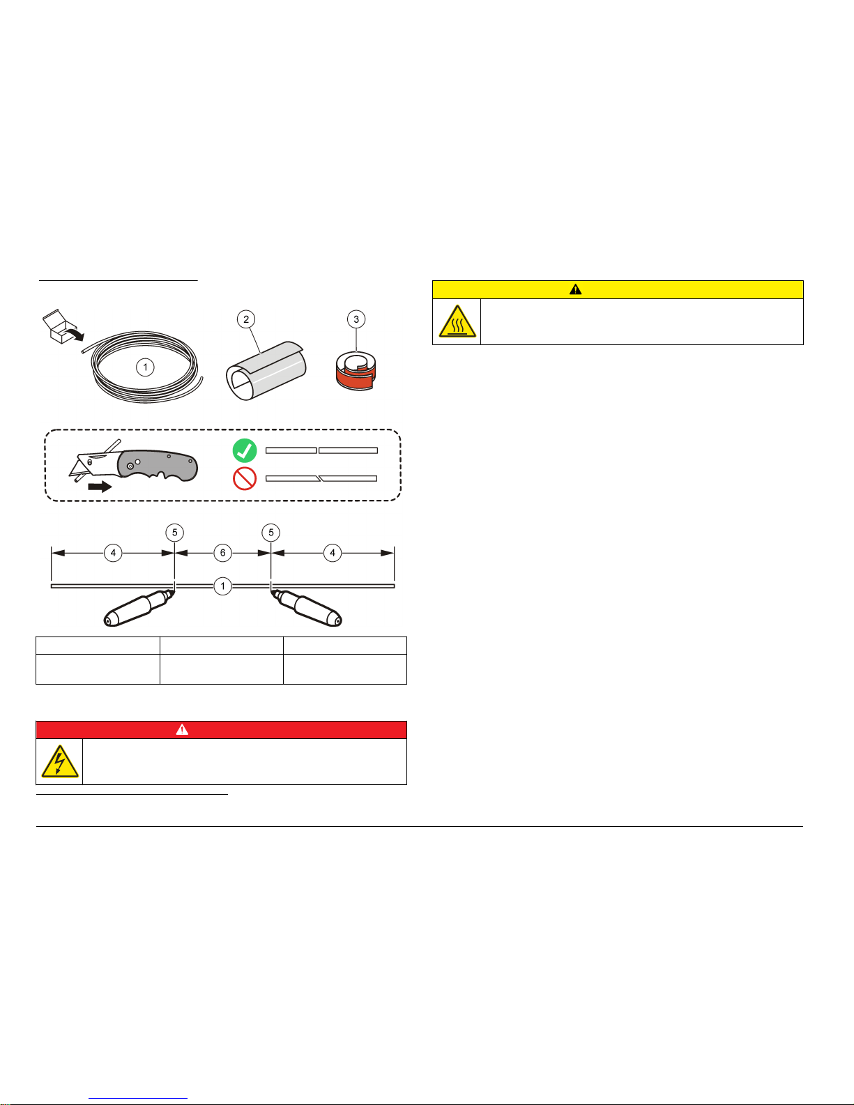
Figure 6 Tubing preparation
1 Tubing 3 Thermal tape, heater 5 Start and stop marks
2 Thermal tape, high
temperature
4 Tubing for other
connections
2
6 Tubing winds around
the lamp/heater block
Replace the lamp
D A N G E R
Electrocution hazard. Remove power from the instrument before doing
maintenance or service activities.
C A U T I O N
Burn hazard. Turn off power and allow the instrument to cool before
this procedure.
Never disconnect the lamp when the power is turned on.
Disconnect the AC input before any part of the instrument is opened.
If the lamp has been recently used, let the instrument temperature cool.
The time required depends upon the temperature set point.
1. Remove all power to the instrument.
2. Remove the top right cover panel.
3. Disconnect the lamp tubing.
4. Remove the lamp from the brackets.
5. Remove the aluminum thermal tape and tubing from the lamp. If the
thermal tape is still in good condition after it is removed, use it on the
new part.
6. To prepare the tubing, refer to Prepare the tubing on page 13.
7. To add tubing around the new lamp, refer to Figure 7.
8. Install the lamp.
9. Connect the tubing.
10. Install the cover panel and secure it.
11. Apply power to the instrument.
2
For lengths and other information, refer to the QuikChem method.
14 English
Page 15

Figure 7 Tubing replacement on the lamp
Replace the heater block
D A N G E R
Electrocution hazard. Remove power from the instrument before doing
maintenance or service activities.
C A U T I O N
Burn hazard. Turn off power and allow the instrument to cool before
this procedure.
Never disconnect the thermocouple and heat stick when the power is
turned on. The result is uncontrolled heating.
Disconnect the AC input before any part of the instrument is opened.
If the heater has been recently used, let the instrument temperature cool.
The time required depends upon the temperature set point.
1. Remove all power to the instrument.
2. Remove the top right cover panel.
3. Disconnect the heater block tubing.
4. Refer to the QuikChem method to make sure that the type and
amount of tubing required for an application is correct.
5. To add tubing around the heater block, refer to Prepare the tubing
on page 13 and Figure 8.
6. To install the heater block, refer to Install the heater block on page 7.
English 15
Page 16

Figure 8 Tubing replacement on the heater block
Troubleshooting
C A U T I O N
Burn hazard. Obey safe handling protocols during contact with hot
sample components.
Decrease the temperature on the instrument to 70 ºC (158 ºF) or less
before the pump tubes are examined. The typical amount of time to
decrease the temperature from 140 ºC (284 ºF) to 70 ºC (158 ºF) is
approximately 10 minutes.
General troubleshooting considerations
The in-line manifolds are different than the standard FIA manifolds. The
main differences are:
• Sample line—The sample line used is usually not a green-green pump
tube. Smaller pump tubes are chosen so that the sample (mixed with
a digestion solution) is put on the heater and on the UV lamp for a
longer period of time.
• Pre-valve sample preparation—The sample line from the sampler
does not go directly to Port 6 of the injection valve. The sample line
mixes with a digestion solution, gets heated, gets UV irradiated, then
goes through the diffusion block or bubble tap membrane, and travels
to Port 6 of the injection valve.
Table 3 shows the most common problems encountered:
Table 3 Troubleshooting guide
Problem Solution
Air spikes in the FIAgram Make sure that the timings agree with the
information in Find the correct timing
on page 11.
Do a degass procedure on the reagents.
Replace the membrane in the dialysis block or
replace the bubble trap membrane.
16 English
Page 17

Table 3 Troubleshooting guide (continued)
Problem Solution
Poor recovery of a QC sample
that consists of complexcyanide
Make sure that the reagents are made fresh.
Make sure that sample flows through all pump
lines.
Make sure that the temperature agrees with
the QuikChem method.
Look at the small hole on the top of the
instrument to see if the UV lamp is turned on. If
not, replace the lamp.
Poor or no recovery of a QC
sample
Examine the pump tubes for flow.
Examine the temperature setting.
Make sure that the reagents are made
correctly.
For the cyanide determination, make sure that
the acid line is put in the digestion solution.
Examine the pump tubes for the acid, the
sample and the acceptor.
Read the QuikChem method notes to learn
more about the expected recoveries.
Table 3 Troubleshooting guide (continued)
Problem Solution
Air flow though the diffusion
block gets very fast, then slows
almost to a stop
Make sure that there are no blockages or
crimps in the reagent and samples tubing.
Make sure that the waste tubing flows freely. If
not, there is excessive back pressure.
Make sure that the instrument waste goes into
a waste container that is applicable for that
solution. Make sure that the tubing is above
the liquid level and that the container is vented
to prevent pressure inside the container. To
prevent cavitation and vapor lock, the waste
container must be at the same level as the
instrument.
Examine the reagent and water bath tubing for
plugs or crimps. Small dirt particles or algae
from a dirty water bath causes flow problems.
Imprecision when running
replicates
Examine the timings in Find the correct timing
on page 11.
Replace the bubble trap membrane.
Make sure that all pump tubes are in good
condition and that there is good liquid flow.
Replacement parts and accessories
W A R N I N G
Personal injury hazard. Use of non-approved parts may cause
personal injury, damage to the instrument or equipment malfunction.
The replacement parts in this section are approved by the
manufacturer.
Note: Product and Article numbers may vary for some selling regions. Contact the
appropriate distributor or refer to the company website for contact information.
English
17
Page 18

Replacement parts
Description Item no.
Tubing, heater block 50028
Tubing, lamp 50728
UV lamp, 6 W —
3
UV lamp, 8 W —
3
Heater block only 25008
4
Thermal tape, heater block 31182
Thermal tape, high temperature, 4-inch 31184
Fuse, 1.6 A, 250 V, slow blow 20205
3
Refer to the QuikChem method, and then contact technical support.
4
Contact technical support.
18 English
Page 19

Table des matières
Caractéristiques à la page 19 Fonctionnement à la page 27
Généralités à la page 19 Maintenance à la page 28
Installation à la page 23 Dépannage à la page 32
Interface utilisateur et navigation
à la page 26
Pièces de rechange et accessoires
à la page 34
Caractéristiques
Les caractéristiques techniques peuvent être modifiées sans préavis.
Caractéristique Détails
Dimensions (l x P x H) 23 x 54 x 14 cm (9 x 21.3 x 5.5 pouces)
Poids 4.5 kg (10 lb)
Exigences électriques 115 VCA, 60 Hz, 1.2 A
230 VCA, 50 Hz, 0.8 A
Fusible 1,6 A, 250 VCA, action retardée
Température de
fonctionnement
5 à 40 °C (41 à 104 °F)
Niveau de pollution 2
Classe de protection 1
Catégorie d’installation II
Humidité de stockage/de
fonctionnement
L'humidité relative maximale s'élève à 80 %
jusqu'à 31 ºC (87,8 °F) avec une diminution
linéaire jusqu'à 50 % d'humidité relative à
40 ºC (104 °F)
Emplacement En intérieur ou en laboratoire
Caractéristique Détails
Lampe UV1— (la plus courante) 354 nm (bleu foncé), type Ushio F6T5BLB
(50717). Utilisée pour la détermination du
cyanure.
254 nm (transparente), G6T5 (50775). Utilisée
pour la détermination de l'azote total ou du
phosphore total
Certifications Marquage CE ; répertorié par les normes de
sécurité ETL à UL et CSA (cETLus) en
Amérique du Nord.
Garantie 1 an
Généralités
En aucun cas le constructeur ne saurait être responsable des
dommages directs, indirects, spéciaux, accessoires ou consécutifs
résultant d'un défaut ou d'une omission dans ce manuel. Le constructeur
se réserve le droit d'apporter des modifications à ce manuel et aux
produits décrits à tout moment, sans avertissement ni obligation. Les
éditions révisées se trouvent sur le site Internet du fabricant.
Consignes de sécurité
A V I S
Le fabricant décline toute responsabilité quant aux dégâts liés à une application
ou un usage inappropriés de ce produit, y compris, sans toutefois s'y limiter, des
dommages directs ou indirects, ainsi que des dommages consécutifs, et rejette
toute responsabilité quant à ces dommages dans la mesure où la loi applicable le
permet. L'utilisateur est seul responsable de la vérification des risques
d'application critiques et de la mise en place de mécanismes de protection des
processus en cas de défaillance de l'équipement.
Veuillez lire l'ensemble du manuel avant le déballage, la configuration ou
la mise en fonctionnement de cet appareil. Respectez toutes les
déclarations de prudence et d'attention. Le non-respect de cette
1
Reportez-vous à la méthode QuikChem spécifique pour connaître les spécifications de la lampe selon l'application.
Français 19
Page 20

procédure peut conduire à des blessures graves de l'opérateur ou à des
dégâts sur le matériel.
Assurez-vous que la protection fournie avec cet appareil n'est pas
défaillante. N'utilisez ni n'installez cet appareil d'une façon différente de
celle décrite dans ce manuel.
Interprétation des indications de risques
D A N G E R
Indique une situation de danger potentiel ou imminent qui, si elle n'est pas évitée,
entraîne des blessures graves, voire mortelles.
A V E R T I S S E M E N T
Indique une situation de danger potentiel ou imminent qui, si elle n'est pas évitée,
peut entraîner des blessures graves, voire mortelles.
A T T E N T I O N
Indique une situation de danger potentiel qui peut entraîner des blessures
mineures ou légères.
A V I S
Indique une situation qui, si elle n'est pas évitée, peut occasionner
l'endommagement du matériel. Informations nécessitant une attention
particulière.
Etiquettes de mise en garde
Lisez toutes les informations et toutes les étiquettes apposées sur
l’appareil. Des personnes peuvent se blesser et le matériel peut être
endommagé si ces instructions ne sont pas respectées. Un symbole sur
l'appareil est référencé dans le manuel et accompagné d'une déclaration
de mise en garde.
Si l'appareil comporte ce symbole, reportez-vous au manuel
d'utilisation pour consulter les informations de fonctionnement et de
sécurité.
En Europe, depuis le 12 août 2005, les appareils électriques
comportant ce symbole ne doivent pas être jetés avec les autres
déchets. Conformément à la réglementation nationale et européenne
(Directive 2002/96/CE), les appareils électriques doivent désormais
être, à la fin de leur service, renvoyés par les utilisateurs au fabricant,
qui se chargera de les éliminer à ses frais.
Ce symbole indique qu'il existe un risque de choc électrique et/ou
d'électrocution.
Ce symbole indique la nécessité de porter des lunettes de protection.
Ce symbole, s'il figure sur le produit, indique l’emplacement d’un
fusible ou d'un dispositif limiteur de courant.
Ce symbole identifie un risque chimique et indique que seules les
personnes qualifiées et formées pour travailler avec des produits
chimiques sont autorisées à les manipuler ou à réaliser des
opérations de maintenance sur les systèmes associés à l'équipement
et utilisant des produits chimiques.
Ce symbole identifie la présence d’une substance fortement corrosive
ou autre substance dangereuse et donc, un risque de blessure
chimique. Seuls les individus qualifiés et formés pour travailler avec
des produits chimiques doivent manipuler des produits chimiques ou
procéder à des travaux de maintenance sur les systèmes de
distribution chimique associés à l’équipement.
20 Français
Page 21

Ce symbole indique que l’élément signalé peut être chaud et que des
précautions doivent être prises avant de le toucher.
Ce symbole indique la présence d'appareils sensibles aux décharges
électrostatiques et indique que des précautions doivent être prises
afin d'éviter d'endommager l'équipement.
Certification
Règlement canadien sur les équipements causant des
interférences radio, IECS-003, Classe A:
Les données d'essai correspondantes sont conservées chez le
constructeur.
Cet appareil numérique de classe A respecte toutes les exigences du
Règlement sur le matériel brouilleur du Canada.
Cet appareil numérique de classe A répond à toutes les exigences de la
réglementation canadienne sur les équipements provoquant des
interférences.
FCC part 15, limites de classe A :
Les données d'essai correspondantes sont conservées chez le
constructeur. L'appareil est conforme à la partie 15 de la règlementation
FCC. Le fonctionnement est soumis aux conditions suivantes :
1. Cet équipement ne peut pas causer d'interférence nuisible.
2. Cet équipement doit accepter toutes les interférences reçues, y
compris celles qui pourraient entraîner un fonctionnement inattendu.
Les modifications de cet équipement qui n’ont pas été expressément
approuvées par le responsable de la conformité aux limites pourraient
annuler l’autorité dont l’utilisateur dispose pour utiliser cet équipement.
Cet équipement a été testé et déclaré conforme aux limites définies pour
les appareils numériques de classe A, conformément à la section 15 de
la réglementation FCC. Ces limites ont pour but de fournir une protection
raisonnable contre les interférences néfastes lorsque l’équipement
fonctionne dans un environnement commercial. Cet équipement génère,
utilise et peut irradier l'énergie des fréquences radio et, s'il n'est pas
installé ou utilisé conformément au mode d'emploi, il peut entraîner des
interférences dangereuses pour les communications radio. Le
fonctionnement de cet équipement dans une zone résidentielle risque de
causer des interférences nuisibles, dans ce cas l'utilisateur doit corriger
les interférences à ses frais Les techniques ci-dessous peuvent
permettre de réduire les problèmes d'interférences :
1. Débrancher l'équipement de la prise de courant pour vérifier s'il est
ou non la source des perturbations
2. Si l'équipement est branché sur le même circuit de prises que
l'appareil qui subit des interférences, branchez l'équipement sur un
circuit différent.
3. Éloigner l'équipement du dispositif qui reçoit l'interférence.
4. Repositionner l’antenne de réception du périphérique qui reçoit les
interférences.
5. Essayer plusieurs des techniques ci-dessus à la fois.
Remarques relatives aux décharges électrostatiques
A V I S
Dégât potentiel sur l'appareil Les composants électroniques internes
de l'appareil peuvent être endommagés par l'électricité statique, qui
risque d'altérer ses performances et son fonctionnement.
Reportez-vous aux étapes décrites dans cette procédure pour éviter
d'endommager l'appareil par des décharges électrostatiques.
• Touchez une surface métallique reliée à la terre (par exemple, le
châssis d'un appareil, un conduit ou un tuyau métallique) pour
décharger l'électricité statique de votre corps.
• Evitez tout mouvement excessif. Transportez les composants
sensibles à l'électricité statique dans des conteneurs ou des
emballages antistatiques.
• Portez un bracelet spécial relié à la terre par un fil.
• Travaillez dans une zone à protection antistatique avec des tapis de
sol et des sous-mains antistatiques.
Français
21
Page 22

Présentation du produit
Cet instrument contient une lampe UV et un bloc chauffant qui préparent
l'échantillon pour un analyseur. Cet instrument est conçu pour être utilisé
uniquement à l'intérieur. Voir Figure 1.
Figure 1 Présentation du produit
1 Panneau d'affichage 5 Interrupteur
marche/arrêt
9 Vis de serrage
2 Lampe UV 6 Bloc chauffant 10 Couvercle d'accès
3 Thermocouple 7 Connecteur
d'alimentation
11 Témoin de la lampe
UV
4 Tige chauffante 8 Boîte à fusibles 12 Orifices
d'entrée/sortie
d'échantillon
22 Français
Page 23

Composants du produit
Assurez-vous d'avoir bien reçu tous les composants. Voir Figure 2. Si
des éléments manquent ou sont endommagés, contactez
immédiatement le fabricant ou un représentant commercial.
Figure 2 Composants de l'instrument
1 Instrument 3 Clips avec raccords
2 Cordon d'alimentation 4 Bloc chauffant
Installation
A V E R T I S S E M E N T
Dangers multiples. Seul le personnel qualifié doit effectuer les tâches
détaillées dans cette section du document.
Installation du bloc chauffant
Reportez-vous aux illustrations suivantes.
Français 23
Page 24

24 Français
Page 25

Positionnement de l'instrument
A T T E N T I O N
Risque d'inhalation d'ozone. Dans certaines conditions, cet instrument
produit des concentrations d'ozone supérieures aux limites
d'exposition en toute sécurité. Branchez l'évacuation des gaz
d'échappement à une hotte ou vers l'extérieur du bâtiment
conformément aux réglementations locales, régionales et nationales.
Cet instrument peut être utilisé jusqu'à une altitude de 2 000 m
(6 562 pieds). Son utilisation à une altitude supérieure à 2 000 m peut
légèrement augmenter le risque de défaillance de l'isolation, et entraîner
un risque de choc électrique. Le fabricant conseille aux utilisateurs ayant
des questions de contacter l'assistance technique.
Placez l'instrument dans une position où il est facile de le débrancher de
la source d'alimentation.
Placez l'instrument dans une position qui n'obstrue pas l'ouverture
d'aération du ventilateur sur le côté gauche. Evitez tout contact du
cordon d'alimentation avec les surfaces brûlantes des canaux de
mesure QC8500.
Il existe deux options de positionnement :
• Placez l'instrument au-dessus de la partie centrale du système
QuikChem (Figure 3). Vérifiez que le contrôleur du chauffage se
trouve bien sur le côté gauche du système.
• Placez l'instrument en dessous de la pompe péristaltique s'il n'y a pas
de place au-dessus du système QuikChem. La pompe péristaltique se
trouve sur le côté gauche du système QuikChem.
Figure 3 Installation du coupleur
1 Analyseur 3 Tubes de sortie d'échantillon
2 Tubes d'échantillon vers l'analyseur 4 Tubes d'admission d'échantillon
Plomberie
Veillez à utiliser des tubes à la dimension indiquée. Reportez-vous à la
méthode QuikChem pour plus de détails.
Français
25
Page 26

Préparation du réactif et des étalons
1. Reportez-vous à la méthode QuikChem pour en savoir plus sur la
préparation du réactif et des étalons.
2. Lisez toutes les remarques sur le système.
3. Branchez le distributeur comme illustré sur le schéma du distributeur
de la méthode QuikChem.
Branchement du cordon d'alimentation
Eléments à préparer :
• Bloc multiprise protégé contre les surtensions
1. Branchez le cordon d'alimentation à l'instrument. Le cordon
d'alimentation doit correspondre à la tension et au courant
d'alimentation.
2. Branchez le cordon d'alimentation sur un bloc multiprise.
3. Mettez le bloc multiprise sous tension.
4. Mettez l'instrument sous tension.
Démarrage de la pompe péristaltique
Reportez-vous à la section relative au fonctionnement de la pompe dans
le manuel d'utilisation QuikChem pour en savoir plus sur l'installation du
tube de la pompe et l'exploitation de la pompe péristaltique.
Recherchez les fuites
1. Une fois le distributeur installé et tous les tubes de pompe
correctement raccordés, placez toutes les conduites de réactif dans
de l'eau déminéralisée.
2. Vérifiez que le distributeur, la vanne d'injection ou l'instrument ne fuit
pas.
Interface utilisateur et navigation
Figure 4 illustre l'écran et le clavier de l'instrument. Tableau 1 indique les
fonctions des touches.
Figure 4 Ecran et clavier
1 Ecran LED PV 3 Flèche HAUT 5 Afficher/Modifier
2 Ecran LED SV 4 Flèche BAS 6 Enter
Tableau 1 Fonctions des touches
Touche Fonction
Enregistre la modification.
Indique ou modifie le paramètre de température.
Diminue la valeur.
Augmente la valeur.
26 Français
Page 27

Fonctionnement
A V E R T I S S E M E N T
Risque d'exposition chimique. Respectez les procédures de sécurité du
laboratoire et portez tous les équipements de protection personnelle adaptés aux
produits chimiques que vous manipulez. Reportez-vous aux fiches techniques de
sécurité des matériaux (MSDS) pour connaître les protocoles de sécurité.
Réglez la température
Remarque : Ne dépassez pas une température de 60 ºC (140 ºF) sans eau ni
réactif dans le tube.
1. Appuyez sur jusqu'à ce que l'écran affiche SP (PC) (point de
consigne).
2. Appuyez sur les flèches HAUT ou BAS pour augmenter ou diminuer
le point de consigne. L'écran continue à afficher le mode SP (PC).
3. Lorsque vous avez réglé la température, appuyez sur pour
enregistrer les informations dans la mémoire.
4. Appuyez une fois sur . L'écran affiche la température actuelle en
Celsius. Un témoin rouge indique que le chauffage est en marche.
5. Laissez la température se stabiliser.
Recherche de la bonne temporisation
Pour trouver la bonne temporisation dans la méthode fluorométrique
Omnion :
Eléments à préparer :
• Chronomètre ou autre minuterie
• Colorant (fourni avec le système), le colorant rouge offre les meilleurs
résultats
Remarque : En raison des différences de viscosité et de point d'ébullition de
chaque réactif, n'utilisez pas d'eau à la place des réactifs pendant l'essai
colorimétrique.
1. Versez du colorant dans un tube à essai.
2. Créez une méthode dans Omnion. Saisissez tous les paramètres de
temporisation des vannes (période de cycle, l'échantillon atteint la
première vanne, période de charge et période d'injection) et les
paramètres de temporisation de l'échantillonneur.
3. Faites circuler le colorant à la place de l'échantillon. Démarrez la
minuterie lorsque la sonde pénètre dans le tube à essai.
4. Suivez le cheminement du colorant dans le système. Lorsque
l'échantillon arrive à l'orifice 6 au niveau de la vanne d'injection,
arrêtez la minuterie.
5. Notez le temps indiqué, qui correspond au temps mis par
l'échantillon pour atteindre la première vanne. N'oubliez pas de
modifier ce temps au niveau de la temporisation de la vanne dans la
méthode.
6. Enregistrez la méthode et refaites circuler le colorant pour mesurer le
paramètre suivant.
7. Faites circuler le colorant et suivez son cheminement dans le
système. Lorsque le colorant arrive à l'orifice 6, démarrez la
minuterie. C'est à cet instant que la vanne bascule pour la première
fois.
8. Lorsque l'échantillon entre dans l'orifice 6, arrêtez la minuterie.
9. Relevez ce temps et retranchez 5 secondes pour obtenir la période
de charge spécifiée dans la temporisation de la vanne dans la
méthode Omnion.
• La période de cycle est spécifiée dans la méthode (période de
cycle = période de charge + période d'injection).
• La période d'injection est paramétrée automatiquement par le
logiciel une fois la période de cycle et la période de charge
définies.
Etalonnage de l'instrument
1. Placez toutes les conduites de réactif dans leurs flacons de réactif
respectifs.
2. Versez les solutions étalons dans les fioles à étalon.
3. Reportez-vous au manuel d'utilisation de l'analyseur pour lancer un
étalonnage.
Français
27
Page 28

Temporisation de l'eau saumâtre dans la méthode
fluorométrique Omnion
Il est nécessaire de temporiser l'intégration de l'eau saumâtre (ou
manuelle) avec certaines méthodes en ligne. La méthode QuikChem
indique quand une temporisation de l'eau saumâtre est nécessaire.
Pour en savoir plus sur le réglage de la temporisation de l'eau saumâtre,
reportez-vous au manuel du logiciel ou effectuez une recherche avec les
mots-clés programmation événements graphiques ou événements
saumâtre dans le système d'aide Omnion.
Conseils
• N'utilisez pas la vitesse de ralenti de la pompe péristaltique.
• Placez les conduites de réactif dans de l'eau déminéralisée pour
éviter de gaspiller du réactif.
• Vérifiez que l'eau déminéralisée traverse bien le réservoir de lavage.
• En général, la conduite d'échantillon n'est pas un tube de pompe
vert/vert. Reportez-vous à la méthode QuikChem pour connaître le
bon tube de pompe.
• Réglez la pompe péristaltique sur 35.
• Parvenez à la température nécessaire avant de lancer un cycle.
• Laissez les réactifs s'écouler à vitesse normale dans tout le système
pendant au moins 15 minutes avant de lancer un cycle.
• Remplacez la membrane du débulleur une fois par mois, lorsque la
précision laisse à désirer ou en cas de présence constante de bulles
d'air.
• Reportez-vous aux données relatives à la méthode dans la méthode
QuikChem et comparez-les aux résultats. Vérifiez que la hauteur et la
zone du pic sont semblables à celles des étalons de la même
concentration.
• En cas d'utilisation simultanée de l'instrument avec d'autres canaux
fluorométriques standard, vous pouvez utiliser un tube orange/orange
à la place de la conduite d'échantillon vert/vert des canaux standard.
Coupez le tube de la pompe comme n'importe quel autre tube de
pompe de la conduite d'échantillon. Utilisez un colorant pour vérifier
que la temporisation est correcte. Cette modification permet d'utiliser
moins d'échantillon.
Maintenance
D A N G E R
Dangers multiples. Seul le personnel qualifié doit effectuer les tâches
détaillées dans cette section du document.
D A N G E R
Risque d'électrocution Coupez l'alimentation de l'instrument avant
d'effectuer des activités de maintenance ou d'entretien.
A V E R T I S S E M E N T
Risque d'exposition chimique. Respectez les procédures de sécurité
du laboratoire et portez tous les équipements de protection
personnelle adaptés aux produits chimiques que vous manipulez.
Consultez les fiches de données de sécurité (MSDS/SDS) à jour pour
connaître les protocoles de sécurité applicables.
Calendrier de maintenance
Le Tableau 2 présente le calendrier recommandé pour les tâches
d'entretien. Les exigences du site comme les conditions d'utilisation
peuvent augmenter la fréquence de certaines tâches.
Tableau 2 Calendrier d'entretien
Tâche Tous les
jours
Tous les ans Au besoin
Nettoyage de l'instrument
à la page 29
X
Remplacer un fusible à la page 29 X
Préparation des tubes
à la page 30
X X
28 Français
Page 29

Tableau 2 Calendrier d'entretien (suite)
Tâche Tous les
jours
Tous les ans Au besoin
Remplacement de la lampe
à la page 30
X
Remplacement du bloc chauffant
à la page 31
X
Pour connaître les opérations d'entretien spécifiques à une méthode en
particulier, reportez-vous à la méthode QuikChem.
Nettoyage de l'instrument
A V I S
N'exécutez aucune procédure de nettoyage ou de décontamination autre que
celle recommandée par la fabricant. Les autres procédures peuvent
endommager l'instrument. Contactez l'assistance technique pour vérifier que les
procédures n'endommagent pas l'instrument.
1. Eteignez l'instrument. Coupez l'alimentation de l'instrument.
2. Essuyez toutes les projections avant de nettoyer l'instrument.
a. Utilisez de l'hydrogénocarbonate de sodium pour neutraliser les
projections acides.
b. Utilisez de l'eau pour nettoyer la solution d'hydrogénocarbonate
de sodium.
c. Essuyez la surface avec un chiffon non pelucheux.
3. Nettoyez avec de l'eau toutes les surfaces de l'instrument.
4. Essuyez toutes les surfaces de l'instrument avec un chiffon non
pelucheux.
Remplacer un fusible
D A N G E R
Risque d’incendie. Remplacez les fusibles par des fusibles de même
type et de même calibre.
Pour remplacer un fusible, reportez-vous aux étapes illustrées dans
Figure 5.
Figure 5 Remplacement des fusibles
Français 29
Page 30

Préparation des tubes
Pour préparer les tubes, reportez-vous à la méthode QuikChem et à la
Figure 6.
Figure 6 Préparation des tubes
1 Tuyaux 3 Ruban thermique,
chauffage
5 Repères de
démarrage et d'arrêt
2 Ruban thermique,
haute température
4 Tubes pour les autres
raccords
2
6 Le tube s'enroule
autour de la lampe/du
bloc chauffant
Remplacement de la lampe
D A N G E R
Risque d'électrocution Coupez l'alimentation de l'instrument avant
d'effectuer des activités de maintenance ou d'entretien.
A T T E N T I O N
Risque de brûlure. Débranchez l'appareil et laissez-le refroidir avant
d'effectuer cette procédure.
Ne débranchez jamais la lampe si l'instrument est sous tension.
Débranchez l'entrée CA avant d'ouvrir une partie de l'instrument.
Si vous venez d'utiliser la lampe, laissez refroidir la température de
l'instrument. La durée nécessaire dépend du point de consigne de la
température.
1. Mettez l'instrument hors tension.
2. Déposez le panneau de couvercle en haut à droite.
3. Débranchez les tubes de la lampe.
4. Retirez la lampe des supports.
5. Retirez le ruban thermique en aluminium et les tubes de la lampe. Si
le ruban thermique est toujours en bon état après son retrait, utilisezle sur la pièce neuve.
6. Pour préparer le tube, reportez-vous à Préparation des tubes
à la page 30.
7. Pour ajouter du tube autour de la lampe neuve, reportez-vous à la
Figure 7.
8. Posez la lampe.
9. Raccordement du tube.
10. Installez le panneau de couvercle et fixez-le.
11. Mettez l'instrument sous tension.
2
Pour connaître les longueurs et obtenir d'autres informations, reportez-vous à la méthode QuikChem.
30 Français
Page 31

Figure 7 Remplacement du tube sur la lampe
Remplacement du bloc chauffant
D A N G E R
Risque d'électrocution Coupez l'alimentation de l'instrument avant
d'effectuer des activités de maintenance ou d'entretien.
A T T E N T I O N
Risque de brûlure. Débranchez l'appareil et laissez-le refroidir avant
d'effectuer cette procédure.
Ne débranchez jamais le thermocouple et la tige chauffante lorsque
l'instrument est sous tension. Le chauffage ne serait plus contrôlé.
Débranchez l'entrée CA avant d'ouvrir une partie de l'instrument.
Si vous venez d'utiliser le chauffage, laissez retomber la température de
l'instrument. La durée nécessaire dépend du point de consigne de la
température.
1. Mettez l'instrument hors tension.
2. Déposez le panneau de couvercle en haut à droite.
3. Débranchez les tubes du bloc chauffant.
4. Reportez-vous à la méthode QuikChem pour vérifier le type et la
quantité de tubes nécessaires selon l'application.
5. Pour ajouter du tube autour du bloc chauffant, reportez-vous à
Préparation des tubes à la page 30 et à la Figure 8.
6. Pour installer le bloc chauffant, reportez-vous à Installation du bloc
chauffant à la page 23.
Français
31
Page 32

Figure 8 Remplacement du tube sur le bloc chauffant
Dépannage
A T T E N T I O N
Risque de brûlure. Respectez les protocoles de sécurité lorsque vous
manipulez des composants d'échantillon chauds.
Réduisez la température sur l'instrument à 70 ºC (158 ºF) ou moins
avant d'examiner les tubes de la pompe. En général, il faut environ
10 minutes pour faire baisser la température de 140 ºC (284 ºF) à 70 ºC
(158 ºF).
Remarques générales sur le dépannage
Les distributeurs en ligne diffèrent des distributeurs fluorométriques
standard. Les principales différences sont :
• Conduite d'échantillon : la conduite d'échantillon n'est en général pas
un tube de pompe vert/vert. On opte pour des tubes de pompe plus
petits afin de placer l'échantillon (mélangé à une solution de digestion)
sur le chauffage et sur la lampe UV de manière prolongée.
• Préparation d'échantillon en amont de la vanne : la conduite
d'échantillon provenant de l'échantillonneur ne va pas directement à
l'orifice 6 de la vanne d'injection. La conduite d'échantillon se mélange
à une solution de digestion, est chauffée, est irradiée aux UV, puis
traverse le bloc de diffusion ou la membrane du débulleur avant
d'arriver à l'orifice 6 de la vanne d'injection.
Le Tableau 3 répertorie les problèmes les plus fréquents :
Tableau 3 Guide de dépannage
Problème Solution
Pointes d'air dans le mesureur
fluorométrique
Vérifiez que les temporisations correspondent
aux informations de la section Recherche de
la bonne temporisation à la page 27.
Effectuez une procédure de dégazage sur les
réactifs.
Remplacez la membrane du bloc de dialyse
ou remplacez la membrane du débulleur.
32 Français
Page 33

Tableau 3 Guide de dépannage (suite)
Problème Solution
Mauvais rendement d'un
échantillon QC composé de
cyanure complexe
Vérifiez la fraîcheur des réactifs.
Vérifiez que l'échantillon traverse bien toutes
les conduites de pompe.
Vérifiez que la température correspond à la
méthode QuikChem.
Regardez par le petit trou en haut de
l'instrument pour voir si la lampe UV est
allumée. Sinon, remplacez la lampe.
Mauvais rendement ou aucun
rendement d'un échantillon QC
Examinez la circulation dans les tubes de
pompe.
Examinez le réglage de la température.
Vérifiez la bonne composition des réactifs.
Pour la détermination du cyanure, vérifiez
que la conduite d'acide est placée dans la
solution de digestion. Recherchez de l'acide,
de l'échantillon et de l'accepteur dans les
tubes de pompe.
Lisez les remarques de la méthode
QuikChem pour en savoir plus sur les
rendements escomptés.
Tableau 3 Guide de dépannage (suite)
Problème Solution
Le flux d'air qui traverse le bloc
de diffusion est très rapide, puis
ralentit jusqu'à pratiquement
s'arrêter
Vérifiez que les tubes de réactif et
d'échantillon ne sont pas obstrués ou pincés.
Vérifiez que le flux circule librement dans le
tube d'évacuation. Sinon, la contre-pression
est trop élevée.
Vérifiez que l'évacuation de l'instrument est
bien acheminée dans un conteneur de
récupération adapté à la solution. Vérifiez
que les tubes sont au-dessus du niveau de
liquide et que le conteneur est ventilé pour
éviter une pressurisation à l'intérieur du
conteneur. Pour éviter une cavitation ou un
bouchon de vapeur, le conteneur de
récupération doit se trouver au même niveau
que l'instrument.
Vérifiez que les tubes de réactif et de bainmarie ne sont pas obstrués ni pincés. Les
petites particules de saleté ou les algues des
bains-marie souillés créent des problèmes de
circulation.
Imprécision en cas de répétitions Examinez les temporisations à la section
Recherche de la bonne temporisation
à la page 27.
Remplacez la membrane du débulleur.
Vérifiez que tous les tubes de pompe sont en
bon état et que le flux y circule bien.
Français 33
Page 34

Pièces de rechange et accessoires
A V E R T I S S E M E N T
Risque de blessures corporelles. L'utilisation de pièces non
approuvées comporte un risque de blessure, d'endommagement de
l'appareil ou de panne d'équipement. Les pièces de rechange de cette
section sont approuvées par le fabricant.
Remarque : Les numéros de référence de produit et d'article peuvent dépendre
des régions de commercialisation. Prenez contact avec le distributeur approprié ou
consultez le site web de la société pour connaître les personnes à contacter.
Pièces de rechange
Description Article n°
Tube, bloc chauffant 50028
Tube, lampe 50728
Lampe UV, 6 W —
3
Lampe UV, 8 W —
3
Bloc chauffant seul 25008
4
Ruban thermique, bloc chauffant 31182
Ruban thermique, haute température, 4 pouces 31184
Fusible, 1.6 A, 250 V, écoulement faible 20205
3
Reportez-vous à la méthode QuikChem, puis contactez l'assistance technique.
4
Contactez l’assistance technique.
34 Français
Page 35

Tabla de contenidos
Especificaciones en la página 35 Operación en la página 43
Información general en la página 35 Mantenimiento en la página 44
Instalación en la página 39 Solución de problemas
en la página 48
Interfaz del usuario y navegación
en la página 42
Piezas de repuesto y accesorios
en la página 50
Especificaciones
Las especificaciones están sujetas a cambios sin previo aviso.
Especificación Detalles
Dimensiones (An x Pr x Al) 23 x 54 x 14 cm (9 x 21,3 x
5,5 pulg.)
Peso 4,5 kg (10 libras)
Requisitos de energía 115 V CA, 60 Hz, 1,2 A
230 V CA, 50 Hz, 0,8 A
Fusible 1,6 A, 250 V CA, quemado lento
Temperatura de funcionamiento 5 a 40 °C (41 a 104 °F)
Grado de contaminación 2
Clase de protección 1
Tipo de instalación II
Humedad en
almacenamiento/funcionamiento
La humedad máxima relativa es del
80% para temperaturas de hasta
31°C (87,8 °F), y disminuye de
forma lineal hasta una humedad
relativa del 50% a 40 °C (104 °F)
Ubicación En interior o en laboratorio
Especificación Detalles
Lámpara UV1—(más común) 354 nm (azul oscuro), tipo Ushio
F6T5BLB (50717). Utilícese con la
determinación de cianuro.
254 nm (transparente),
G6T5 (50775). Utilícese con la
determinación de nitrógeno total o
de fósforo total.
Certificaciones Marca CE; cumple con los
requisitos de seguridad
establecidos por ETL, UL y CSA
(CETLus) para Norteamérica.
Garantía 1 año
Información general
En ningún caso el fabricante será responsable de ningún daño directo,
indirecto, especial, accidental o resultante de un defecto u omisión en
este manual. El fabricante se reserva el derecho a modificar este
manual y los productos que describen en cualquier momento, sin aviso
ni obligación. Las ediciones revisadas se encuentran en la página web
del fabricante.
Información de seguridad
A V I S O
El fabricante no es responsable de ningún daño debido a un mal uso de este
producto incluyendo, sin limitación, daños directos, fortuitos o circunstanciales y
reclamaciones sobre los daños que no estén recogidos en la legislación vigente.
El usuario es el responsable de la identificación de los riesgos críticos y de tener
los mecanismos adecuados de protección de los procesos en caso de un posible
mal funcionamiento del equipo.
Lea todo el manual antes de desembalar, instalar o trabajar con este
equipo. Ponga atención a todas las advertencias y avisos de peligro. El
no hacerlo puede provocar heridas graves al usuario o daños al equipo.
1
Consulte el método QuikChem específico si desea obtener las especificaciones de la lámpara para una aplicación.
Español 35
Page 36

Asegúrese de que la protección proporcionada por el equipo no está
dañada. No utilice ni instale este equipo de manera distinta a lo
especificado en este manual.
Uso de la información sobre riesgos
P E L I G R O
Indica una situación potencial o de riesgo inminente que, de no evitarse,
provocará la muerte o lesiones graves.
A D V E R T E N C I A
Indica una situación potencial o inminentemente peligrosa que, de no evitarse,
podría provocar la muerte o lesiones graves.
P R E C A U C I Ó N
Indica una situación potencialmente peligrosa que podría provocar una lesión
menor o moderada.
A V I S O
Indica una situación que, si no se evita, puede provocar daños en el instrumento.
Información que requiere especial énfasis.
Etiquetas de precaución
Lea todas las etiquetas y rótulos adheridos al instrumento. En caso
contrario, podrían producirse heridas personales o daños en el
instrumento. El símbolo que aparezca en el instrumento se comentará
en el manual con una declaración de precaución.
Este símbolo (en caso de estar colocado en el equipo) hace
referencia a las instrucciones de uso o a la información de seguridad
del manual.
El equipo eléctrico marcado con este símbolo no se podrá desechar
por medio de los sistemas europeos públicos de eliminación después
del 12 de agosto de 2005. De acuerdo con las regulaciones locales y
nacionales europeas (Directiva UE 2002/96/EC), ahora los usuarios
de equipos eléctricos en Europa deben devolver los equipos viejos o
que hayan alcanzado el término de su vida útil al fabricante para su
eliminación sin cargo para el usuario.
Este símbolo indica que hay riesgo de descarga eléctrica y/o
electrocución.
Este símbolo indica la necesidad de usar protectores para ojos.
Este símbolo, cuando aparece en un producto, identifica la ubicación
de un fusible o de un limitador de corriente.
Este símbolo identifica un peligro químico e indica que el trabajo se
debe ejecutar exclusivamente por personal cualificado y entrenados
en el manejo de productos químicos, el cual debe realizar también
los trabajos de mantenimiento en el sistema de alimentación de
productos químicos asociado con este equipo.
Este símbolo identifica la presencia de una sustancia corrosiva fuerte
u otras sustancias peligrosas, y el riesgo de lesiones químicas.
Solamente los individuos calificados y entrenados para trabajar con
químicos deben manejar estos productos y realizar mantenimiento de
los sistemas de entrega de químicos asociados con el equipo.
Este símbolo indica que la pieza marcada podría estar caliente y que
debe tocarse con precaución.
Este símbolo indica la presencia de dispositivos susceptibles a
descargas electrostáticas. Asimismo, indica que se debe tener
cuidado para evitar que el equipo sufra daño.
Certificación
Reglamentación canadiense sobre equipos que provocan
interferencia, IECS-003, Clase A
Registros de pruebas de control del fabricante.
Este aparato digital de clase A cumple con todos los requerimientos de
las reglamentaciones canadienses para equipos que producen
interferencias.
36
Español
Page 37

Cet appareil numérique de classe A répond à toutes les exigences de la
réglementation canadienne sur les équipements provoquant des
interférences.
FCC Parte 15, Límites Clase "A"
Registros de pruebas de control del fabricante. Este dispositivo cumple
con la Parte 15 de las normas de la FCC estadounidense. Su operación
está sujeta a las siguientes dos condiciones:
1. El equipo no puede causar interferencias perjudiciales.
2. Este equipo debe aceptar cualquier interferencia recibida, incluyendo
las interferencias que pueden causar un funcionamiento no deseado.
Los cambios o modificaciones a este equipo que no hayan sido
aprobados por la parte responsable podrían anular el permiso del
usuario para operar el equipo. Este equipo ha sido probado y
encontrado que cumple con los límites para un dispositivo digital Clase
A, de acuerdo con la Parte 15 de las Reglas FCC. Estos límites están
diseñados para proporcionar una protección razonable contra las
interferencias perjudiciales cuando el equipo está operando en un
entorno comercial. Este equipo genera, utiliza y puede irradiar energía
de radio frecuencia, y si no es instalado y utilizado de acuerdo con el
manual de instrucciones, puede causar una interferencia dañina a las
radio comunicaciones. La operación de este equipo en un área
residencial es probable que produzca interferencia dañina, en cuyo caso
el usuario será requerido para corregir la interferencia bajo su propio
cargo. Pueden utilizarse las siguientes técnicas para reducir los
problemas de interferencia:
1. Desconecte el equipo de su fuente de alimentación para verificar si
éste es o no la fuente de la interferencia.
2. Si el equipo está conectado a la misma toma eléctrica que el
dispositivo que experimenta la interferencia, conecte el equipo a otra
toma eléctrica.
3. Aleje el equipo del dispositivo que está recibiendo la interferencia.
4. Cambie la posición de la antena del dispositivo que recibe la
interferencia.
5. Trate combinaciones de las opciones descritas.
Indicaciones para la descarga electroestática
A V I S O
Daño potencial al instrumento. Los delicados componentes
electrónicos internos pueden sufrir daños debido a la electricidad
estática, lo que acarrea una disminución del rendimiento del
instrumento y posibles fallos.
Consulte los pasos en este procedimiento para evitar daños de
descarga electrostática en el instrumento:
• Toque una superficie metálica a tierra como el chasis de un
instrumento, un conducto metálico o un tubo para descargar la
electricidad estática del cuerpo.
• Evite el movimiento excesivo. Transporte los componentes sensibles
a la electricidad estática en envases o paquetes anti-estáticos.
• Utilice una muñequera conectada a tierra mediante un alambre.
• Trabaje en una zona sin electricidad estática con alfombras de piso y
tapetes para mesas de trabajo antiestáticas.
Descripción general del producto
Este instrumento contiene una lámpara UV y un bloque calefactor que
preparan la muestra para el analizador. Este instrumento está diseñado
sólo para uso en interior. Consulte la Figura 1.
Español 37
Page 38

Figura 1 Descripción general del producto
1 Panel de
visualización
5 Interruptor de
encendido
9 Tornillo de mariposa
2 Lámpara UV 6 Bloque calefactor 10 Cubierta de acceso
3 Termopar 7 Conector de
alimentación
11 Indicador de
lámpara UV
4 Bastón de calor 8 Caja de fusibles 12 Puertos de
entrada/salida de la
muestra
Componentes del producto
Asegúrese de haber recibido todos los componentes. Consulte la
Figura 2. Si faltan artículos o están dañados, póngase en contacto con
el fabricante o el representante de ventas inmediatamente.
Figura 2 Componentes del instrumento
1 Instrumento 3 Clavijas con uniones
2 Cable de alimentación 4 Bloque calefactor
38 Español
Page 39

Instalación
A D V E R T E N C I A
Peligros diversos. Sólo el personal cualificado debe realizar las tareas
descritas en esta sección del documento.
Instalación del bloque calefactor
Consulte los pasos ilustrados que se muestran a continuación.
Español 39
Page 40

40 Español
Page 41

Colocación del instrumento
P R E C A U C I Ó N
Peligro de inhalación de ozono. En determinadas condiciones, este
instrumento produce concentraciones de ozono superiores a los
límites de exposición segura. Dirija los gases residuales a una
campana extractora o al exterior del edificio de acuerdo con las
normativas locales, regionales y nacionales.
Este instrumento está clasificado para una altitud de 2000 m (6562 pies)
como máximo. El uso de este instrumento a una altitud superior a los
2000 m puede aumentar ligeramente la posibilidad de fallo del
aislamiento, lo que puede generar riesgo de descarga eléctrica. El
fabricante recomienda ponerse en contacto con el servicio de asistencia
técnica en caso de dudas.
Coloque el instrumento en una posición que permita desconectarlo
fácilmente de la fuente de alimentación.
Coloque el instrumento de forma que la abertura de ventilación situada
en el lateral izquierdo no quede bloqueada. No permita que el cable de
alimentación entre en contacto con superficies calientes en los canales
de medición del QC8500.
Existen dos opciones de colocación del instrumento:
• Coloque el instrumento sobre el módulo principal del sistema
QuikChem (Figura 3). Asegúrese de que el controlador del calefactor
se encuentre en el lateral izquierdo del sistema.
• Si no hay espacio disponible sobre el sistema QuikChem, coloque el
instrumento debajo de la bomba peristáltica. La bomba peristáltica se
encuentra en el lateral izquierdo del sistema QuikChem.
Figura 3 Instalación del manguito de unión
1 Analizador 3 Tubos de salida de la muestra
2 Tubos de muestra en dirección al
analizador
4 Tubos de entrada de la muestra
Fontanería
Asegúrese de utilizar el tamaño de tubos especificado. Consulte el
método del QuikChem para ver más información.
Español
41
Page 42

Preparación de los reactivos y las soluciones
estándar
1. Consulte el método QuikChem para obtener información sobre la
preparación de reactivos y soluciones estándar.
2. Lea todas las notas del sistema.
3. Conecte el distribuidor como se muestra en el gráfico del método
QuikChem.
Conexión del cable de alimentación
Recopilación de elementos:
• Regleta de alimentación con protección contra sobrevoltaje
1. Conecte el cable de alimentación al instrumento. Debe evaluarse la
corriente y la tensión de alimentación del cable de alimentación.
2. Conecte el cable de alimentación a la regleta de alimentación.
3. Encienda la regleta de alimentación.
4. Encienda el interruptor de alimentación del instrumento.
Inicie la bomba peristáltica
Consulte la sección de funcionamiento de la bomba en el manual de
usuario de QuikChem si desea obtener información sobre la instalación
de los tubos de la bomba y sobre el funcionamiento de la bomba
peristáltica.
Comprobación de fugas
1. Cuando el distribuidor esté instalado y todos los tubos de la bomba
están acoplados de forma segura, coloque todos los tubos de
reactivos en agua desionizada.
2. Asegúrese de que no existen fugas en el distribuidor, la válvula de
inyección o el instrumento.
Interfaz del usuario y navegación
Figura 4 muestra el teclado y la pantalla del instrumento. Tabla 1 indica
las funciones de las teclas.
Figura 4 Pantalla y teclado
1 Pantalla de LED con
valor acutal (PV)
3 Flecha ARRIBA 5 Mostrar/cambiar
2 Pantalla de LED con
valor establecido (SV)
4 Flecha ABAJO 6 Intro
Tabla 1 Funciones de las teclas
Tecla Función
Almacena el cambio
Muestra o cambia el ajuste de temperatura.
Reduce el valor.
Incrementa el valor.
42 Español
Page 43

Operación
A D V E R T E N C I A
Peligro por exposición química. Respete los procedimientos de seguridad del
laboratorio y utilice el equipo de protección personal adecuado para las
sustancias químicas que vaya a manipular. Consulte los protocolos de seguridad
en las hojas de datos actuales de seguridad de los materiales (MSDS).
Ajuste de la temperatura
Nota: No deje que la temperatura del instrumento supere los 60 ºC (140 ºF) sin
que haya agua o reactivos en los tubos.
1. Pulse hasta que la pantalla muestre SP (set point [punto de
control]).
2. Pulse las flechas hacia ARRIBA o hacia ABAJO para aumentar o
disminuir el punto de control. El monitor seguirá mostrando el modo
SP.
3. Cuando haya ajustado la temperatura, pulse para guardar la
información en la memoria.
4. Pulse una vez. La pantalla muestra la temperatura actual en
grados Celsius. Una luz roja muestra que el calefactor está
encendido.
5. Deje que la temperatura se estabilice.
Ajuste del tiempo correcto
Para averiguar el tiempo correcto del sistema de análisis por inyección
en flujo de Omnion:
Recopilación de elementos:
• Cronómetro o cualquier otro temporizador
• Tinte (suministrado con el sistema): el tinte rojo proporciona los
mejores resultados
Nota: Debido a las diferencias entre la viscosidad y el punto de ebullición de cada
reactivo, no utilice agua el lugar de reactivos durante la prueba de tinción.
1. Introduzca tinte en el tubo de ensayo.
2. Cree un método en Omnion. Introduzca los parámetros de tiempo de
la válvula (período de cada ciclo, momento en que la muestra
alcanza la primera válvula, período de carga y período de inyección)
y los parámetros de tiempo del muestreador.
3. Analice el tinte como una muestra. Inicie el temporizador cuando la
sonda entre en el tubo de ensayo.
4. Siga el recorrido del tinte por el sistema. Cuando la muestra llegue al
puerto 6, en la válvula de inyección, detenga el temporizador.
5. Registre el tiempo, es decir, el tiempo que tarda la muestra en llegar
a la primera válvula. Asegúrese de cambiar este valor en el ajuste de
tiempo de la válvula del método.
6. Guarde el método y realice un nuevo análisis con el tinte para medir
el parámetro siguiente.
7. Realice el análisis y vuelva a seguir el tinte por todo el sistema.
Cuando el tinte llegue al puerto 6, inicie el temporizador. En este
instante, la válvula se activará por primera vez.
8. Cuando la masa de líquido de la muestra llegue al puerto 6, detenga
el temporizador.
9. Registre este tiempo y reste 5 segundos para obtener el período de
carga que se especifica en el ajuste de tiempo de la válvula del
método Omnion.
• El período del ciclo se especifica en el método (período del ciclo =
período de carga + período de inyección).
• El software establece automáticamente el período de inyección
cuando se introducen los períodos del ciclo y de carga.
Calibración del instrumento
1. Coloque todos los tubos de reactivo en sus respectivas botellas.
2. Vierta las soluciones patrón en los viales.
3. Consulte el manual de usuario del analizador para comenzar una
calibración.
Español
43
Page 44

Tiempos de salobridad en el sistema de análisis por
inyección en flujo de Omion
Algunos de los métodos en línea hacen necesaria ajustar el tiempo de la
integración de salobridad (o manual). El método QuikChem muestra
cuándo es necesario ajustar el tiempo de salobridad.
Si desea obtener más información sobre cómo ajustar el tiempo de
salobridad, consulte el manual de software o realice una búsqueda de
las palabras clave "programación de eventos gráficos" o "eventos de
salobridad" en el sistema de ayuda de Omnion.
Consejos
• No utilice la velocidad en espera de la bomba peristáltica.
• Introduzca los tubos de reactivo en agua desionizada para evitar
desperdiciar reactivo.
• Asegúrese de que el agua desionizada fluye a través del depósito de
lavado.
• El tubo de muestra generalmente no es un tubo de bomba verdeverde. Consulte el método QuikChem para averiguar cuál es el tubo
correcto de la bomba.
• Ajuste la bomba peristáltica a 35.
• Espere hasta que se obtenga la temperatura necesaria antes de
iniciar un análisis.
• Deje que los reactivos fluyan a una velocidad normal por todo el
sistema durante al menos 15 minutos antes de comenzar un análisis.
• Cambie la membrana del sistema de eliminación de burbujas una vez
al mes, cuando disminuya la precisión o cuando las burbujas de aire
sean un problema constante.
• Consulte los datos de asistencia del método en el método QuikChem
y compare los datos con los resultados. Asegúrese de que la altura
de pico y el área son similares para soluciones patrón de la misma
concentración.
• Si se utiliza simultáneamente el instrumento y otros canales estándar
para el análisis por inyección en flujo, la línea de muestra para los
canales estándar puede cambiarse de verde-verde a naranja-naranja.
Corte el tubo de la bomba como cualquier otro tubo de muestra de la
bomba. Utilice una solución de tinción para asegurarse de que los
tiempos son correctos. Este cambio utiliza menos muestra.
Mantenimiento
P E L I G R O
Peligros diversos. Sólo el personal cualificado debe realizar las tareas
descritas en esta sección del documento.
P E L I G R O
Peligro de electrocución. Retire la alimentación eléctrica del
instrumento antes de realizar actividades de mantenimiento o
reparación.
A D V E R T E N C I A
Peligro por exposición a productos químicos. Respete los
procedimientos de seguridad del laboratorio y utilice el equipo de
protección personal adecuado para las sustancias químicas que vaya
a manipular. Consulte los protocolos de seguridad en las hojas de
datos de seguridad actuales (MSDS/SDS).
Cronograma de mantenimiento
Tabla 2 muestra el cronograma de recomendado para las tareas de
mantenimiento. Los requerimientos del lugar y las condiciones de
operación pueden aumentar la frecuencia de algunas tareas.
Tabla 2 Programa de mantenimiento
Tarea
Diariamente
Anualmente Según sea
necesario
Limpieza del instrumento
en la página 45
X
Sustituya un fusible
en la página 45
X
Preparación de los tubos
en la página 45
X X
44 Español
Page 45

Tabla 2 Programa de mantenimiento (continúa)
Tarea
Diariamente
Anualmente Según sea
necesario
Cambie la lámpara
en la página 46
X
Sustitución del bloque
calefactor en la página 47
X
Si desea obtener información sobre las tareas de mantenimiento de un
método específico, consulte el método de QuikChem.
Limpieza del instrumento
A V I S O
No utilice ningún procedimiento de limpieza o descontaminación diferente a los
recomendados por el fabricante. Si emplea otros procedimientos, puede dañar el
instrumento. Póngase en contacto con el servicio de asistencia técnica para
asegurarse de que los procedimientos no dañan el instrumento.
1. Apague el instrumento. Corte la energía del instrumento.
2. Limpie cualquier derramamiento antes de limpiar el instrumento en
sí.
a. Utilice bicarbonato para neutralizar los derramamientos ácidos.
b. Retire la solución de bicarbonato con agua.
c. Seque el área con un paño que no suelte pelusa.
3. Limpie todas las superficies del instrumento con agua.
4. Seque todas las superficies del instrumento con un paño que no
suelte pelusa.
Sustituya un fusible
P E L I G R O
Peligro de incendio. Utilice el mismo tipo de fusibles con la misma
corriente nominal cuando los sustituya.
Para sustituir un fusible, consulte los pasos ilustrados en la Figura 5.
Figura 5 Sustitución de fusibles
Preparación de los tubos
Para preparar los tubos, consulte el método QuikChem y la Figura 6.
Español
45
Page 46

Figura 6 Preparación de los tubos
1 Tubos 3 Cinta térmica,
calefactor
5 Marcas de inicio y de
final
2 Cinta térmica,
temperatura alta
4 Tubos para otras
conexiones
2
6 Distancia del tubo
que rodea la
lámpara/el bloque del
calefactor
Cambie la lámpara
P E L I G R O
Peligro de electrocución. Retire la alimentación eléctrica del
instrumento antes de realizar actividades de mantenimiento o
reparación.
P R E C A U C I Ó N
Peligro de quemadura. Desconecte el instrumento de la alimentación
eléctrica y deje que se enfríe antes de continuar con este
procedimiento.
Nunca desconecte la lámpara si la alimentación está encendida.
Desconecte la entrada de CA antes de abrir cualquier parte del
instrumento.
Si ha utilizado la lámpara recientemente, espere a que el instrumento se
enfríe. El tiempo necesario depende del punto de control que haya
establecido para la temperatura.
1. Desconecte la alimentación del instrumento.
2. Retire el panel protector de la parte superior derecha.
3. Desconecte los tubos de la lámpara.
4. Retire la lámpara de los soportes.
5. Retire la cinta adhesiva térmica de aluminio y los tubos de la
lámpara. Si la cinta térmica sigue estando en buenas condiciones
tras retirarla, póngala en la parte nueva.
6. Para preparar los tubos, consulte Preparación de los tubos
en la página 45.
7. Para colocar los tubos alrededor de la nueva lámpara, consulte la
Figura 7.
8. Instale la lámpara.
9. Conecte los tubos.
10. Instale el panel protector de la cubierta y asegúrelo.
11. Conecte la alimentación al instrumento.
2
Si desea obtener información sobre las longitudes u otro tipo de información, consulte el método QuikChem.
46 Español
Page 47

Figura 7 Sustitución del tubo en la lámpara.
Sustitución del bloque calefactor
P E L I G R O
Peligro de electrocución. Retire la alimentación eléctrica del
instrumento antes de realizar actividades de mantenimiento o
reparación.
P R E C A U C I Ó N
Peligro de quemadura. Desconecte el instrumento de la alimentación
eléctrica y deje que se enfríe antes de continuar con este
procedimiento.
No desconecte nunca el termopar y el bastón de calor si la corriente
está conectada, ya que esto daría lugar a un calentamiento
descontrolado.
Desconecte la entrada de CA antes de abrir cualquier parte del
instrumento.
Si ha utilizado el calefactor recientemente, espere a que el instrumento
se enfríe. El tiempo necesario depende del punto de control que haya
establecido para la temperatura.
1. Desconecte la alimentación del instrumento.
2. Retire el panel protector de la parte superior derecha.
3. Desconecte los tubos del bloque calefactor.
4. Consulte el método QuikChem para asegurarse de que el tipo y la
cantidad de tubos necesarios para la aplicación son correctos.
5. Para colocar los tubos alrededor del bloque calefactor, consulte
Preparación de los tubos en la página 45 y la Figura 8.
6. Para instalar el bloque calefactor, consulte Instalación del bloque
calefactor en la página 39.
Español
47
Page 48

Figura 8 Tubos de repuesto para el bloque calefactor
Solución de problemas
P R E C A U C I Ó N
Peligro de quemadura. Obedezca los protocolos de manipulación
mientras esté en contacto con los componentes de la muestra.
Disminuya la temperatura del instrumento a 70 ºC (158 ºF) o a una
temperatura inferior antes de examinar los tubos de la bomba. La
cantidad de tiempo necesaria para disminuir la temperatura de 140 ºC
(284 ºF) a 70 ºC (158 ºF) es aproximadamente 10 minutos.
Consideraciones generales de solución de problemas
Los distribuidores en línea son diferentes de los distribuidores para
análisis por inyección en flujo estándar. A continuación se indican las
diferencias principales:
• Tubo de muestra: el tubo de muestra no suele un tubo de bomba
verde-verde. Generalmente se eligen tubos de bomba de menor
tamaño para que la muestra (mezclada con una solución de
digestión) se coloque en el calefactor y en la lámpara UV durante más
tiempo.
• Preparación de la muestra antes de la válvula: la línea de muestra
desde el muestreador no va directamente hasta el puerto 6 de la
válvula de inyección. La línea de muestra se mezcla con una solución
de digestión, se calienta y se radia con luz UV; a continuación,
atraviesa un bloque de difusión o la membrana de una llave para
burbujas y viaja hasta el puerto 6 de la válvula de inyección.
Tabla 3 muestra los problemas más habituales:
48 Español
Page 49

Tabla 3 Guía de solución de problemas
Problema Solución
El aire entra en FIAgram Asegúrese de que los tiempos se ajustan a la
información de Ajuste del tiempo correcto
en la página 43.
Someta los reactivos a un proceso de
desgasificación.
Sustituya la membrana del bloque de diálisis
o la membrana del sistema de eliminación de
burbujas.
Recuperación defectuosa de una
muestra para control de calidad
con cianuro complejo
Asegúrese de que los reactivos se han
preparado recientemente.
Asegúrese de que la muestra fluye por todos
los tubos de muestra.
Asegúrese de que la temperatura es acorde
con el método QuikChem.
Observe el pequeño orificio en la parte
superior del instrumento para ver si la
lámpara UV está encendida. Si no lo
estuviese, sustituya la lámpara.
Recuperación defectuosa o nula
de una muestra para control de
calidad
Examine los tubos de la bomba para ver si
existe flujo.
Examine los ajustes de temperatura.
Asegúrese de que los reactivos se han
preparado recientemente.
Para la determinación de cianuro, asegúrese
de que el tubo de ácido se coloca en la
solución de digestión. Examine los tubos de
la bomba para el ácido, la muestra y el
aceptor.
Lea las notas del método QuikChem para
obtener más información sobre las
recuperaciones que debe obtener.
Tabla 3 Guía de solución de problemas (continúa)
Problema Solución
El flujo de aire a través del
bloque de difusión se obtiene
muy rápido y después desciende
el ritmo hasta casi pararse
Asegúrese de que no hay obstrucciones ni
pliegues en los tubos de muestras o de
reactivos.
Asegúrese de que el fluido pasa libremente a
través de los tubos de desechos. Si no lo
hace, significa que existe una contrapresión
excesiva.
Asegúrese de que los desechos del
instrumento van a parar a un recipiente de
desechos adecuado para esa solución.
Asegúrese de que los tubos se encuentran
por encima del nivel de líquido y de que el
recipiente tiene ventilación para evitar que
exista presión en su interior. Para evitar la
cavitación y el bloqueo de vapor, el recipiente
de desechos debe encontrarse al mismo
nivel que el instrumento.
Compruebe que los tubos del reactivo y del
baño de agua no presentan obstrucciones ni
pliegues. Las pequeñas partículas de
suciedad o las algas procedentes de un baño
de agua sucio pueden causar problemas de
flujo.
Imprecisión al analizar réplicas Examine los tiempos en Ajuste del tiempo
correcto en la página 43.
Sustituya la membrana del sistema de
eliminación de burbujas.
Asegúrese de que todos los tubos de la
bomba están en buenas condiciones y el
líquido fluye bien.
Español 49
Page 50

Piezas de repuesto y accesorios
A D V E R T E N C I A
Peligro de lesión personal. El uso de piezas no aprobadas puede
causar lesiones personales, daños al instrumento o un mal
funcionamiento del equipo. Las piezas de repuesto que aparecen en
esta sección están aprobadas por el fabricante.
Nota: Los números de producto y artículo pueden variar para algunas regiones de
venta. Comuníquese con el distribuidor correspondiente o visite el sitio Web de la
compañía para obtener la información de contacto.
Piezas de repuesto
Descripción Referencia
Tubos, bloque calefactor 50028
Tubos, lámpara 50728
Lámpara UV, 6 W —
3
Lámpara UV, 8 W —
3
Solo bloque calefactor 25008
4
Cinta térmica, bloque calefactor 31182
Cinta térmica, temperatura alta, 10,2 cm (4 pulg) 31184
Fusible , 1.6 A, 250 V, quemado lento 20205
3
Consulte el método QuikChem y póngase en contacto con el servicio de asistencia técnica.
4
Póngase en contacto con el servicio de asistencia técnica.
50 Español
Page 51

目录
技术指标 第 51 页 操作 第 58 页
基本信息 第 51 页 维护 第 59 页
安装 第 54 页 故障排除 第 63 页
用户界面及导航 第 57 页 更换部件与附件 第 63 页
技术指标
产品规格如有变化,恕不另行通知。
规格 详细信息
尺寸(宽 x 深 x 高)
23 x 54 x 14 cm (9 x 21.3 x 5.5 in.)
重量
4.5 kg (10 lb)
电源要求
115 VAC, 60 Hz, 1.2 A
230 VAC, 50 Hz, 0.8 A
保险丝 1.6 A,250 VAC,缓熔
工作温度 5 至 40 °C (41 至 104 °F)
污染程度
2
保护等级
1
安装类别
II
存放/操作湿度 对于 31 °C (87.8 °F) 以下的温度,最大相对湿度为
80%,温度达到 40 °C (104 °F) 时,相对湿度线性降到
50%
取样点 室内或实验室
规格 详细信息
紫外灯1—(最常用) 354 nm(深蓝色),Ushio F6T5BLB (50717) 型。用于
测定氰化物。
254 nm(透明),G6T5 (50775)。用于测定总氮或总
磷。
认证 CE 认证;符合北美 ETL - UL 认证和 CSA 安全标准
(cETLus)。
保修 1 年
基本信息
对于因本手册中的任何不足或遗漏造成的直接、间接、特别、附带或结果
性损失,制造商概不负责。制造商保留随时更改本手册和手册中描述的产
品的权利,如有更改恕不另行通知或承担有关责任。修订版可在制造商的
网站上找到。
安全信息
注 意
对于误用和滥用造成的产品损坏,制造商概不负责,包括但不限于:直接、附带和
间接的损坏,并且对于适用法律允许的最大程度的损坏也不承担任何责任。用户唯
一的责任是识别重大应用风险和安装适当的系统,以在设备可能出现故障时保护工
艺。
请在拆开本设备包装、安装或使用本设备前,完整阅读本手册。特别要注
意所有的危险警告和注意事项。否则,可能会对操作者造成严重的人身伤
害,或者对设备造成损坏。
确保设备提供的保护没有受损。请勿以本手册指定方式之外的其它方式使
用或安装本设备。
危险信息使用
危 险
表示潜在的或紧急的危险情况,如果不加以避免,将会导致死亡或严重伤害。
1
关于某一应用所需的紫外灯规格,请参阅特定的 QuikChem 方法。
中文
51
Page 52

警 告
表示潜在或非常危险的情形,如不避免,可能导致严重的人身伤亡。
警 告
表示潜在的危险情形,可能导致一定程度的人身伤害。
注 意
表明如不加以避免则会导致仪器损坏的情况。需要特别强调的信息。
警告标签
请阅读贴在仪器上的所有标签和标记。如未遵照这些安全标签的指示操
作,则可能造成人身伤害或仪器损坏。仪器上的符号在手册中通过警告说
明参考。
本符号如果出现在仪器中,则表示参考说明手册中的操作和/或安全信
息。
使用此符号标记的电气设备在 2005 年 8 月 12 日后,不能通过欧洲公
共垃圾系统进行处理。为遵守欧洲地区和国家法规(欧盟指令
2002/96/EC),欧洲电气设备使用者现在必须将废弃或到期的设备送
还制造商进行处理,使用者不必支付任何费用。
此标志指示存在电击和/或电死危险。
此标志指示需要戴上防护眼镜。
仪表上如有此标志,则指示保险丝或者限流装置的位置。
此标志指示化学伤害危险,并指示只有合格的人员以及在处理化学制
品方面受过培训的人员,才能处理化学制品,或执行与该设备有关的
化学制品传送系统的维护工作。
此标志指示存在强烈的腐蚀性物质或其它危险物质,并且存在化学伤
害危险。只有合格的人员以及在处理化学制品方面受过培训的人员,
才能处理化学制品,或执行与该设备有关的化学制品传送系统的维护
工作。
此标志指示标记的部件可能很热,接触时务必小心谨慎。
此标志指示存在静电释放 (ESD) 敏感的设备,且必须小心谨慎以避
免设备损坏。
认证
加拿大无线电干扰产生设备法规(Canadian Radio Interference-
Causing Equipment Regulation),IECS-003,A 类:
制造商支持测试记录留存。
此 A 类数字设备符合加拿大干扰产生设备法规的所有要求。
Cet appareil numérique de classe A répond à toutes les exigences de la
réglementation canadienne sur les équipements provoquant des
interférences.
FCC 第 15 部分,“A”类限制
制造商支持测试记录留存。该设备符合 FCC 规定第 15 部分的要求。设
备操作满足以下两个条件:
1. 本设备不会造成有害干扰。
2. 本设备必须接受任何接收到的干扰,包括可能导致意外操作的干扰。
若未经负责出具符合声明的一方明确同意擅自对本设备进行改动或改装,
可能会导致取消用户操作该设备的权限。本设备已经过测试,符合 FCC
规定第 15 部分中确定的 A 类数字设备限制。 这些限制专门提供当设备在
商业环境下工作时针对有害干扰的合理保护。该设备产生、使用和放射无
线电射频能量,如果不按照说明手册的要求对其进行安装和使用,可能会
对无线电通讯造成有害干扰。本设备在居民区工作时可能会产生有害干
扰,这种情况下用户须自行承担费用消除这种干扰。以下方法可用于减少
干扰问题:
52
中文
Page 53

1. 断开设备的电源,以便确证它是干扰源与否。
2. 如果设备与遭受干扰的仪器连接到相同的插座,将设备连接到其他插
座。
3. 将设备从接受干扰的仪器边上移开。
4. 重新定位受干扰仪器的接收天线。
5. 同时尝试以上多项措施。
静电放电 (ESD) 注意事项
注 意
可能导致仪器损坏。静电会损害精密的内部电子组件,从而导致仪器性
能降低或最终出现故障。
请参阅此流程中的步骤以防止 ESD 损坏仪器:
• 接触接地金属表面(如仪器外壳、金属导管或管道),以将静电排出机
壳外。
• 避免过度移动。运送静电敏感的组件时,请使用抗静电容器或包装。
• 配戴连接到接地线缆的腕带。
• 使用抗静电地板垫和工作台垫,以使工作区具备静电安全性。
产品概述
本仪器含有紫外灯和加热部件,用于为分析仪制备样品。本仪器仅限室内
使用。请参阅 图 1。
图 1 产品概述
1 显示面板 5 电源开关 9 拇指夹
2 紫外灯 6 加热部件 10 检修盖
3 热电偶 7 电源接头 11 紫外灯指示灯
4 加热棒 8 保险丝盒 12 进样/出样口
产品组件
确保已收到所有组件。请参阅 图 2。如有任何物品丢失或损坏,请立即联
系制造商或销售代表。
中文
53
Page 54

图 2 仪器组件
1 仪器 3 带管接的夹子
2 电源线 4 加热部件
安装
警 告
多种危险。只有合规的专业人员才能从事文件中本部分所述的任务。
安装加热部件
请参阅应遵循的示例步骤。
54
中文
Page 55

中文
55
Page 56

仪器布置
警 告
臭氧吸入风险。在某些情况下,此仪器产生的臭氧浓度高于安全暴露限
制。根据当地、地区和国家要求,将废气排入通风柜或建筑物外部。
本仪器的额定工作海拔为最高 2000 m (6562 ft)。在海拔高于 2000 m 的
条件下使用本仪器会略微增大绝缘失效的风险,从而可能导致触电危险。
制造商建议,用户如有疑虑,请联系技术支持。
将仪器放在易于断开电源的位置。
仪器的位置应确保风扇左侧通风口不被堵塞。不要使电源线接触
QC8500 测量通道的热表面。
提供两种布置选择:
• 将仪器放在 QuikChem 系统核心部分 (图 3) 的顶部。确保加热器控制
器位于系统左侧。
• 如果 QuikChem 系统顶部没有空间,将仪器置于蠕动泵下方。蠕动泵
位于 QuikChem 系统的左侧。
图 3 安装联轴器
1 分析仪 3 出样管
2 分析仪样品管 4 进样管
装设管线
确保使用指定的管子尺寸。有关详情,请参阅 QuikChem 方法。
制备试剂和标样
1. 关于试剂和标样的制备详情,请参阅 QuikChem 方法。
2. 阅读所有的系统注释。
3. 按照 QuikChem 方法歧管图,连接歧管。
56
中文
Page 57

连接电源线
需准备的物品:
• 浪涌保护电源板
1. 将电源线连接至仪器。电源线必须符合电源的电压和电流额定值。
2. 将电源线连接至电源板。
3. 接通电源板。
4. 打开仪器的电源开关。
启动蠕动泵
关于泵管安装及蠕动泵操作的详情,请参阅 QuikChem 用户手册中的泵
操作一节。
查找泄漏
1. 安装歧管并牢固连接所有泵管之后,将所有溶剂管放入去离子水中。
2. 确保歧管、注射阀或仪器没有泄漏问题。
用户界面及导航
图 4 所示是仪器显示屏和键盘。表 1 介绍了键的功能。
图 4 显示屏和键盘
1 PV LED 显示屏 3 向上箭头 5 显示/更改
2 SV LED 显示屏 4 向下箭头 6 Enter
表 1 键功能
键 功能
保存更改。
显示或更改温度设置。
减少数值。
增加数值。
中文
57
Page 58

操作
警 告
化学品暴露风险。遵守实验室安全规程,穿戴适用于所处理化学品的所有个人防护
装备。有关安全协议,请参考当前材料安全数据表 (MSDS)。
设定温度
注: 试管中没有水或试剂时,温度不要高于
60 ºC (140 ºF)
。
1. 按下 直到显示屏显示 SP(设定值)。
2. 按向上或向下箭头可增加或减少设定值。显示屏继续显示 SP 模式。
3. 设定温度时,按 将信息保存在内存中。
4. 按 一次。显示屏将显示当前摄氏温度。红灯表明加热器已接通电
源。
5. 让温度稳定下来。
查找正确计时
在 Omnion FIA 中查找正确的计时:
需准备的物品:
• 秒表或其他的计时器
• 染料(系统随附)- 红色染料效果最好
注: 由于每种试剂具有不同的粘度和沸点,所以在染料测试期间不要用水取代试
剂。
1. 将一些染料放入一支测试管中。
2. 在 Omnion 中创建一种方法。输入所有的阀计时参数(循环周期、样
品到达第一个阀的时间、加载周期及注射周期)以及取样器定时参
数。
3. 将染料作为样品进行分析。当探头进入试管时,启动计时器。
4. 使染料流经系统。当样品到达注射阀的端口 6 时,关闭计时器。
5. 记下时间,即是样品到达第一个阀的时间。确保在本方法的阀计时中
更改该时间。
6. 保存该方法,再次运用染料样品,测定下一个参数。
7. 运用染料并使之流经系统。当染料到达端口 6 时,启动计时器。首次
切换阀门时,需要立即启动计时器。
8. 当样品单元到达端口 6 时,关闭计时器。
9. 记下该时间并减去 5 秒钟,从而获得 Omnion 方法阀计时指定的加载
周期。
• 该方法指定了循环周期(循环周期 = 加载周期 + 注射周期)。
• 定义了循环周期和加载周期后,注射周期便由软件自动设定。
校准仪器
1. 将所有试剂管放入相应试剂瓶中。
2. 将标准溶液倒入标样瓶中。
3. 请参阅分析仪用户手册,开始校准。
Omnion FIA Brackish 计时
有些联机方法需要使用 Brackish(或手动)集成计时。QuikChem 方法可
显示何时需要 Brackish 计时。
如要详细了解如何设置 Brackish 计时,请参阅软件手册,或在 Omnion
帮助系统中搜索关键词“图形事件编程”或“Brackish 事件”。
提示
• 不要使用蠕动泵的备用速度。
• 将试剂管放入去离子水中,以免浪费试剂。
• 确保去离子水流经清洗槽。
• 样品管通常不是绿-绿色泵管。请参阅 QuikChem 方法使用正确的泵
管。
• 将蠕动泵设为 35。
• 开始分析之前达到所需温度。
• 开始分析之前,使试剂在整个系统内以正常速度至少流动 15 分钟。
• 一个月更换一次除泡隔膜,或在精度不良或不断出现气泡问题时更换。
• 查看 QuikChem 方法中的支持数据,并与分析结果对比。确保相同浓
度的标样具有相似的峰高和峰面积。
58
中文
Page 59

• 如果仪器与其他的标准 FIA 通道同时运行,标准通道的样品管可以从
绿-绿色变为橙-橙色。按照与任何其他的样品管线泵管类似的方式切断
泵管。用一种染料溶液确保计时正确。这种更改使用样品量更少。
维护
危 险
多种危险。只有合规的专业人员才能从事文档中本部分所述的任务。
危 险
电击致命危险。执行维护或维修活动前,请断开仪器的电源连接。
警 告
化学品暴露风险。遵守实验室安全规程,穿戴适用于所处理化学品的所
有个人防护装备。有关安全协议,请参阅当前安全数据表
(MSDS/SDS)。
维护计划
表 2 显示建议的维护任务计划。设施要求和工作条件可能会增加某些任务
的频率。
表 2 维护计划
任务 每天 每年 按需要
清洁仪器 第 59 页
X
更换保险丝 第 59 页
X
准备导管 第 60 页
X X
表 2 维护计划 (续)
任务 每天 每年 按需要
更换紫外灯 第 61 页
X
更换加热部件 第 62 页
X
对于单个方法特定的维护任务,请参阅 QuikChem 方法。
清洁仪器
注 意
除了厂家推荐的流程之外,不要使用任何其他的清洁或去污流程。其他清洁流程会
损坏仪器。请咨询技术支持人员,确保清洁流程不会损坏仪器。
1. 关闭仪器。断开仪器的电源。
2. 清洁仪器之前,先清理溢出液。
a. 用小苏打中和酸性溢出液。
b. 用清水冲去小苏打溶液。
c. 用无棉布擦干该部分。
3. 用水清洗仪器的所有表面。
4. 用无棉布擦干仪器的所有表面。
更换保险丝
危 险
火灾危险。使用类型和额定电流相同的保险丝对原来的保险丝进行更
换。
如要更换保险丝,请参阅 图 5 图示步骤。
中文
59
Page 60

图 5 保险丝更换
准备导管
准备导管时,请参阅 QuikChem 方法和 图 6。
图 6 准备导管
1 导管 3 加热器导热胶带 5 起止标记
2 高温导热胶带 4 用于其他连接的导管26 导管缠绕在灯/加热部
件上
2
关于导管的长度以及其他信息,请参阅 QuikChem 方法。
60
中文
Page 61

更换紫外灯
危 险
电击致命危险。执行维护或维修活动前,请断开仪器的电源连接。
警 告
烫伤危险。执行此程序前,关闭电源并使仪器冷却。
请勿在通电时断开紫外灯。
打开仪器的任何部分之前,首先断开交流输入端。
如果最近使用了紫外灯,让仪器降温。所需冷却时间取决于设定的温度。
1. 切断仪器的所有电源。
2. 拆下右上方盖板。
3. 断开灯管。
4. 从支架上取下紫外灯。
5. 从紫外灯上拆下铝导热胶带和导管。如果导热胶带拆下之后仍然状况
良好,可以在新零件上使用。
6. 如要准备导管,请参阅 准备导管 第 60 页。
7. 如要在新灯周围添加导管,请参阅 图 7。
8. 安装紫外灯。
9. 连接灯管。
10. 安装盖板并固定。
11. 将仪器连接到电源。
图 7 导管在紫外灯上的布置
中文
61
Page 62

更换加热部件
危 险
电击致命危险。执行维护或维修活动前,请断开仪器的电源连接。
警 告
烫伤危险。执行此程序前,关闭电源并使仪器冷却。
请勿在通电时断开热电偶和加热棒。否则无法控制加热。
打开仪器的任何部分之前,首先断开交流输入端。
如果最近使用了加热器,让仪器降温。所需冷却时间取决于设定的温度。
1. 切断仪器的所有电源。
2. 拆下右上方盖板。
3. 断开加热部件的导管。
4. 请按 QuikChem 方法确保导管的类型和数量符合应用要求。
5. 如要在加热部件周围添加导管,请参阅 准备导管 第 60 页和 图 8。
6. 如要安装加热部件,请参阅 安装加热部件 第 54 页。
图 8 导管在加热部件上的布置
62
中文
Page 63

故障排除
警 告
灼伤危险。接触灼热样本组件时,请遵守安全操作协议。
检查泵管之前使仪器温度降到 70 ºC (158 ºF) 或更低。温度从 140 ºC
(284 ºF) 降到 70 ºC (158 ºF) 通常大约需要 10 分钟。
一般故障排除考虑因素
内联歧管不同于标准的 FIA 歧管。主要区别在于:
• 样品管线 — 所使用的样品管线通常不是绿-绿色泵管。选择较小泵管,
使样品(混有消解液)长期处于加热器和紫外灯环境中。
• 阀前样品制备 — 取样器的样品管线不会直接进入注射阀的端口 6 中。
样品管线混入消解液之后进行加热,经紫外线照射后流经扩散部件或除
泡隔膜,继而进入注射阀接口 6 中。
表 3 所示是最常见的问题:
表 3 故障排除指南
问题 解决方案
FIAgram 中出现空气峰值 确保计时符合 查找正确计时 第 58 页 中的信
息。
对试剂执行脱气流程。
更换渗析部件中的隔膜,或更换除泡隔膜。
含有氰化物络合物的 QC 样品回收不良确保试剂属于新制试剂。
确保样品流经所有泵管。
确保温度符合 QuikChem 方法。
查看仪器顶部小孔,确认紫外灯是否亮起。
否则更换紫外灯。
表 3 故障排除指南 (续)
问题 解决方案
QC 样品回收不良或无法回收 检查泵管中的流量。
检查温度设置。
确保正确制备试剂。
对于氰化物测定,确保酸液管位于消解液
中。检查酸液、样品及受体对应的泵管。
阅读 QuikChem 方法注释,了解预期的回收
详情。
空气流经扩散部件时速度变得很
快,随后变慢至几乎不流动
确保试剂管和样品管无堵塞或卷曲。
确保废液管中的液体可自由流动。否则说明
背压过高。
确保仪器废液进入相应的废液容器中。确保
导管位于液位以上,并且保持容器通气,以
防容器内部产生压力。为了防止产生气蚀和
气阻,废液容器必须与仪器处于同一水平
面。
检查试剂和水浴管是否堵塞或卷曲。脏水清
洗中细小的污物颗粒或藻类会造成流动问
题。
重复分析精度低 检查 查找正确计时 第 58 页 中的计时功能。
更换除泡隔膜。
确保所有泵管状况良好,并且液体流动良
好。
更换部件与附件
警 告
人身伤害危险。使用未经批准的部件可能造成人身伤害、仪器损坏或设
备故障。本部分中的更换部件均经过制造商的批准。
中文
63
Page 64

注: 一些销售地区的产品和物品数量可能有所不同。请与相关分销商联系或参阅公
司网站上的联系信息。
更换部件
说明 物品编号
加热部件导管
50028
紫外灯导管
50728
6 W 紫外灯
—
3
8 W 紫外灯
—
3
仅限加热部件
25008
4
加热部件导热胶带
31182
高温导热胶带,4 英寸
31184
保险丝,1.6 A,250 V,缓熔
20205
3
请先参阅 QuikChem 方法,然后联系技术支持人员。
4
请联系技术支持部门。
64
中文
Page 65

Page 66

HACH COMPANY World Headquarters
P.O. Box 389, Loveland, CO 80539-0389 U.S.A.
Tel. (970) 669-3050
(800) 227-4224 (U.S.A. only)
Fax (970) 669-2932
orders@hach.com
www.hach.com
HACH LANGE GMBH
Willstätterstraße 11
D-40549 Düsseldorf, Germany
Tel. +49 (0) 2 11 52 88-320
Fax +49 (0) 2 11 52 88-210
info-de@hach.com
www.de.hach.com
HACH LANGE Sàrl
6, route de Compois
1222 Vésenaz
SWITZERLAND
Tel. +41 22 594 6400
Fax +41 22 594 6499
©
Hach Company/Hach Lange GmbH, 2013-2014, 2017. All rights reserved. Printed in U.S.A.
*DOC022.97.80338*
 Loading...