

Page 1
www.habeyusa.com www.habeyusa.com
BIS-6621
Quick Setup Guide
Packing List
Description QTY
BIS-6621 1
Power Cable 1
Power Adaptor 1
Wi Antenna 1
SATA Connector 1
Mounting Rack 1
Mounting Screw Package 1
Safety Warning:
The use and installation of this system should only be performed by
professionals. Improper installation of any electronic device or electrical
component can result in serious injury or death. Please make sure that all
safety precautions are taken into account.
21015 Commerce Pointe Drive, Walnut, CA 91789
Page 2
Install Guide
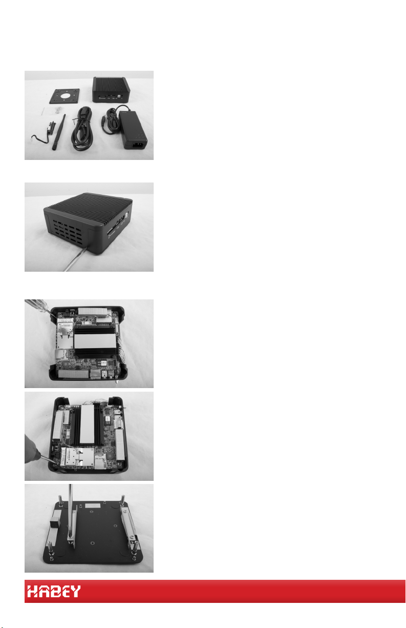
Step 1 - Inspect Contents
Step 2 - Remove Top Cover
Step 3 - Install 2.5” HDD
Unpack all package contents and inspect
each component. Make sure all included
parts and accessories are present.
Using a phillips head screw driver, remove
the four screws on the sides of the enclosure.
Using a phillips small head screw driver,
remove the four screws on the bottom cover.
Using a phillips regualr head screw driver,
remove the four screws on the board.
Seperate the bottom cover from the board
and then remove the HDD mounting bracket
from the backplane.
Page 3
www.habeyusa.com www.habeyusa.com
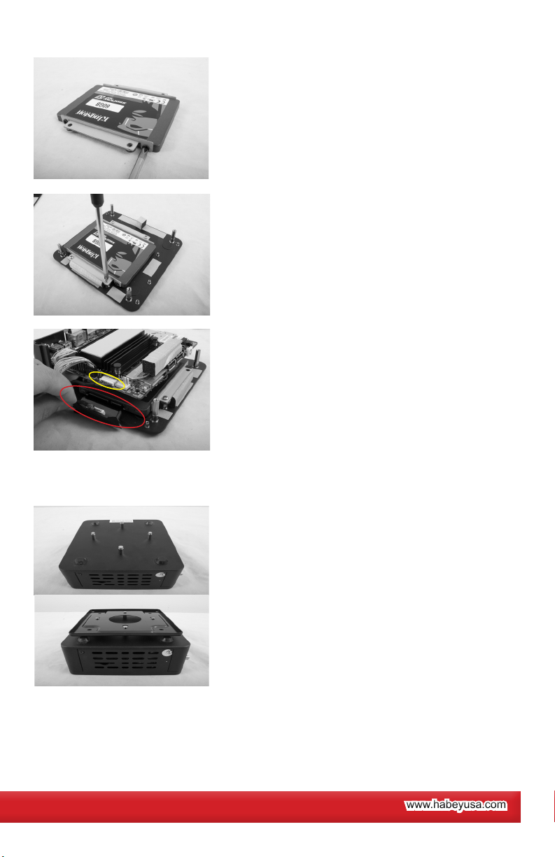
Step 4 - Rack Mounting
Mount the HDD on the tray with the four
screws in the small plastic package.
Then mount the HDD bracket back onto the
backplane and x it with four screws.
Use the SATA connector to connect the HDD
with the board as marked in circles.
Take out the four mounting screws from the
screw package and tighen them into the four
mounting holes on the bottom cover.
Place the mounting rack on the top of the
four screws.
Step 5 - Hardware Installation Complete
Your system is now ready. Connect the power cable to a power source and
press the power button on the front of the system.
Page 4
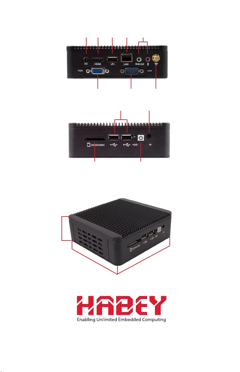
Input / Output
Rear Panel
DC
LANUSBHDMI
Audio
Front Panel
Dimensions
48.77mm/ 1.92”
133.35mm/ 5.25”
VGA COM
2x USB2.0
SD/MS/MMC Socket
ANT
IR
Power Button
127mm/ 5”
21015 Commerce Pointe Drive, Walnut, CA 91789
www. habeyusa.com
Copyright©2014. Habey USA. All Rights Reserved. Version 1.
 Loading...