


Art. no. 05713070001400
V14 E15
Pellett Stove
HSP 2.17
Installation and operating instructions
! Important manufacturer’s instructions!
Please observe the following instructions:
Quality of wood pellets:
Depending on the manufacturer there are light, dark, shorter and longer pellets. And the quality of one delivery may
differ from another even from the same supplier. The standards for wood pellets are becoming more and more strict
but wood is wood and has its own characteristics regarding ash and clinker.
Cleaning requirements:
As soon as you find ash and clinker deposits in the cold combustion pot, it must be cleaned. See operating
instructions! If this is not done, there will be more and more clinker. Then the device will no longer be able to ignite
properly. Pellets may pile up in the combustion pot. In extreme cases, this can reach all the way back to the pellet
chute. Backfire in the pellet container and smouldering in the pellet tank might possibly result. This will destroy
your device and is not covered by the guarantee.
For maximum working life:
Arrange for commissioning by your trained stove supplier.
Observe the daily check as described and more frequently if you have received new pellet deliveries or when
the device is brought back into use after the summer.
Carefully read through all the operating instructions and retain them.
Type number:

2
Index of contents
1. Description 3
2. General instructions, safety instructions 3
3. Installation of the pellet stove and connection to
the chimney 4
4.The pellet stove’s functional characteristics 6
5. The pellet stove’s operating statuses: 6
5.1. Ignition phase 6
5.2. Heating mode 6
5.3. Burner test / cleaning 7
5.4. Cooling down 7
5.5. Standby 7
5.6. Safety shutdown (shutdown) 7
5.7. Faults 7
5.8. Switching off – operating status OFF 8
5.9. Power cut 8
6. Description of operator console keys 8
6.1. Operator console 8
6.2. Description of the symbols 8
6.2.1 Display software version after power connection
8
6.2.2 Setting the language at initial 8
6.3. Standard screen /welcome page 9
6.3..1 Room temperature display in energy saving
mode 9
6.3..2 Setting the operating mode „On“ 9
6.3..3 Setting target room temperature 9
6.4. Main menu 9
6.4..1 Setting the date and time 10
6.4..2 Setting the language 10
6.4..3 Desription – Heating profile 10
6.4..4 Desription – Display brightness - contrast
setting 10
6.4..5 Software Version 11
6.4..6 Fault screen (top field in the display) 11
6.4..7 Description – Key lock (child-safe) 11
7. Operating the pellet stove 11
7.1. Fuel 11
7.2. Commissioning your pellet stove 12
8. Cleaning and maintenance work 12
8.1. Cleaning the surface 13
8.2. Cleaning the glass panel 13
8.3. Clean combustion chamber” function instruction 13
8.4. Cleaning the combustion pot -weekly 13
8.5. Cleaning the pellet container - annual maintenance
14
8.6. Cleaning the flue gas passes-annual maintenance 14
8.7. Cleaning the induced draught housing and fan 16
9. Description of the components 16
9.1. Storage container (pellet tank) 16
9.2. Screw conveyor motor / screw conveyor 16
9.3. Combustion pot with tray: 17
9.4. Electric ignition 17
9.5. Control unit 17
9.6. Operator console 18
9.6..1 Backlighting 18
9.6..2 Activating the backlighting 18
9.7. Induced draught fan with rotation speed feedback 18
9.8. Flame or combustion chamber temperature sensor
(combustion chamber thermosensor) 18
9.9. Flue gas thermosensor 18
9.10. Room temperature sensor 18
9.11. OC – Overheat cutout 19
9.12. Combustion chamber cladding 19
9.13. Flue tube connection 19
9.14. Mains cable and master switch 19
10. Technical data 20
11. Faults, causes, correction 21
11.1. Error messages on the display 21
11.2. General faults 24
12. Type plate: Symbol 25
13. Replacement parts list 27
14. Circuit diagram 28
15. Guarantee 30

3
Congratulations! You are the owner of a HAAS + SOHN
pellet stove, a quality product. Please read through
these instructions carefully. They will tell you all about
the functions and operation of this stove, which will
increase the utility of this device and extend its working
life. What is more, with the correct heating you can save
fuel and protect the environment.
We can only give a guarantee on our products if you
observe the following instructions in these installation
and operating instructions. In addition, the stove must be
correctly installed so as to prevent possible accidents.
Look after these instructions well, then you will be able
to familiarise yourself with the correct operation of your
stove at the start of every heating period.
Note:
The installation and operating instructions given in this
manual may differ entirely or in part from public authority
instructions. In that event, the public authority
instructions always apply! The drawings in these
instructions are not to scale and serve only as
illustrations.
1. Description
Pellet stoves are particularly suitable for the constant
heating of residential and work rooms. The
HAAS+SOHN pellet stove is set up to operate in fully
automatic mode, with a choice of 2 operating modes
(“Heating” and “Auto” with a weekly programme).
Depending on the room temperature and on the model,
a volume of fuel for a maximum of 30 hours of constant
operation may be stored in the built-in storage container.
The fuel is fed automatically from the pellet tank to the
grate via a screw conveyor, with the quantity of fuel
automatically being adjusted to the relevant heat output.
The internal control unit regulates the ignition phase, the
heating phase and the cooling down phase, thereby
guaranteeing safe operation of the pellet stove. The
operator console, which consists of a display and four
function keys, is built into the pellet tank cover.
The heating of the air in the room and the creation of
comfortable living conditions is mainly achieved by
convection. This allows you to quickly warm up even
cold rooms that have been unheated for a lengthy
period. The cooler air of the room enters the stove at the
bottom of the cladding, is heated and flows out again at
the top in the area of the slats. The proportion of radiant
heat is given off by radiation in the area of the viewing
window of the combustion chamber door and from the
stove’s metal surfaces.
2. General instructions, safety instructions
Before commissioning the pellet stove read the
entire installation and operating instructions through
thoroughly.
Only permitted handling gear with sufficient
loadbearing capacity may be used for moving your
device.
Your heating device is not suitable for use as a
ladder or mounting frame.
For the installation of your stove, the fire protection
authority’s regulations and the local building
regulations in force at the installation site are to be
observed and you should also discuss this with the
district heating inspector. He will also check that the
connection of the device to the fireplace is carried
out correctly.
All the checks required by law have been performed
on your stove. The mandatory indices regarding
technical combustion efficiency and flue gas
emissions are observed.
The pellet stove may be connected to a multiple-use
chimney provided that the chimney dimensions
permit this according to DIN EN 13384-1 or DIN EN
13384-2. The supply pressure must be at least 6
Pa and should be 15 Pa as a maximum.
The combustion chamber door may be opened only
for cleaning and maintenance during operating
status “Off”. Otherwise it is to be kept closed – even
when the stove is not operating in order to avoid
affecting other heating appliances and the
associated risks.
An adequate supply of fresh air must be guaranteed
to the room where the stove is installed. However,
the pellet stove offers you the option of a direct
connection to the outside air via a suitable air duct.
So operation independent of the air in the room is
possible. (See Section 3 “Installation of the pellet
stove and connection to the chimney”).
Attention! The pellet stove may not be set
up to be operated jointly with the home’s air
conditioning and ventilation units.
The chimney (fireplace or flue) must be made of
stainless steel or ceramics (glazed internally) and
suitable for wet operation so that it cannot rot.
The pellet stove cannot be connected to the mains
electricity until it has been correctly connected to the
fireplace.

4
The pellet stove may not be installed in the open
air!
Attention! The mains cable plug must remain freely
accessible after installation.
The pellet stove may only be operated with standard
wood pellets (6 mm diameter). (See Section 7.1
“Fuel”).
The protective grille located in the pellet container
must not be removed.
Attention! The Pelletto stove may only be
operated with the tank cover closed.
Placing non-heat-resistant materials or objects on
the stove or within the specified minimum distances
is forbidden. Here please note in particular that
during “Standby” operating status, the stove may
unexpectedly and unintentionally start heating when
the room temperature falls below the desired
temperature.
Never use liquid fuels to ignite the pellet stove or to
revive existing embers.
With the burning up of fuels, heat energy is
released, leading to strong heating of the heating
device’s surfaces (e.g. doors, door and control
handles, viewing window panels, side walls, front
wall, flue tubes). Touching these parts without
suitable heat protection gloves or a tool is to be
avoided!
The device ignites by itself in “Standby” mode.
Because of the heat generated on the panel, make
sure that no-one who is unfamiliar with the operation
of the pellet stove is unsupervised in the room where
it is installed.
Bring these risks to your children’s and guests
attention!
In particular, any cleaning staff should be informed
and instructed regarding the possible unexpected
heating up of the stove.
Placing non-heat-resistant objects on or near the
heating device (even when it is cold, since it can
ignite again by itself) is forbidden!
Do not lay any laundry on the stove to dry!
Clotheshorses for drying clothes and the like must
be positioned at sufficient distance from the heating
device – fire risk!
When operating your heating device, it is forbidden
to work with highly flammable or explosive
substances in the same room or an adjacent one!
3. Installation of the pellet stove and connection to
the chimney
The packaging on your new pellet stove gives it optimum
protection against damage. Nevertheless, damage may
have occurred to the stove or to accessories in transit.
Please therefore check your stove after unpacking for
damage and completeness! Report any defects or
anything missing to your specialist stove dealer without
delay!
The packaging on your stove is by and large
environmentally neutral. The timber packaging is not
untreated. The timber, the cardboard and the films can
be taken without problems to your local recycling centre.
For the correct operation of your pellet stove it is
important that it stands horizontally.
The room temperature sensor that is located on the back
wall has a length of about 1.5 m and should be
positioned hanging free at the back.
Figure 1: Back connections
1 = Mains electricity socket
2 = OC overheat cutout
3 = Room temperature sensor
4 = Fume elbow 80 mm
5 = Outside air connection 40 mm
6 = Bottom of back wall
6
1
3
5
2
4

5
Floor protection
The floor is to be protected from the radiant heat from
the area of the viewing window (combustion chamber).
In addition, for practical reasons associated with
cleaning it is recommended that you install your pellet
stove on a fireproof base that extends beyond the device
at the back and on the sides by at least 5 cm and at the
front by at least 50 cm. We have floor protection plates
(underlay plates or U plates) in our range of accessories.
If required, you may order them from your specialist
stove dealer. As an alternative, a tile or stone floor is of
course very suitable.
Safety gaps (minimum gaps):
During installation of the stove it is absolutely essential
to observe the official fire protection regulations. Ask
your district heating inspector about this.
The following must be maintained as the minimum
distances from flammable or temperature-sensitive
materials (e.g. furniture, wallpaper, wooden cladding)
and from loadbearing walls. (See drawing):
A 5 cm from the back wall
B 10 cm from the side walls and
C 80 cm in the direction of radiation.
Figure 2: Safety gaps
The chimney (fireplace or flue) must for example be
made of stainless steel or ceramics (glazed internally) so
that it cannot rot. This is necessary because of the low
temperature of flue gases from your pellet stove.
Standard trade flue tubes may be used for the
connection to the fireplace. Approved Flex steel flues
are also suitable.
Since excess pressure may build up at the smoke outlet
because of the way that the pellet stove works with an
induced draught fan, all fume outlet pipes as far as the
intake to the fireplace must be gas-tight. It is also
essential to ensure that the flue tube does not stick out
into the open cross-section of the chimney. The use of
wall lagging is recommended for the insertion into the
chimney. (See Figure 3).
With longer flue gas pipework, horizontal sections and
constrictions must be avoided and specially insulated
flue tubes should be used. Pipework rising in the
direction of the chimney is recommended.
Figure 3: Chimney connection
1 = Wall lagging
2 = Gas-tight pipework
3 = Underlay plate
External air intake:
In airtight buildings, whilst the pellet stove is operating, a
reduction in the oxygen level in the room where the
stove is installed may occur, so adequate ventilation
must be ensured. For this the pellet stove offers you the
option of operating independently of the air in the room.
To do this, connect the air intake elbow located on the
back (diameter: 57 mm) to a hose or a similar suitable
air duct. The end of the air duct must be located in the
open air or in a well-ventilated room within the building.
When installing the pellet stove in combination with
controlled residential room ventilation, the end of the air
intake duct must not be connected to the ventilation
system in an adjacent room with the air connection
system. To ensure sufficient volume of air intake, the
pipe should not be longer than about 3 m and not have
too many bends. This pipe should have a minimum
diameter of 5 cm. (The bigger, the better). If the pipe
goes to the open air, it must end with a downward 90°
bend or with wind protection. (See Figure 4).

6
Figure 4: Wind protection of the air intake pipe
The following table applies to the sizing of the air intake
pipe:
Diameter of the
intake pipe *
Maximum
length *
Max. number of
90° bends
50 mm
0.5 m
1
100 mm
1 m
1
100 mm
3 m
3
*The figures given apply as appropriate. With a flat duct
or similar, a suitable cross-section is to be chosen.
If the pipes are narrower than these dimensions, it may
be that the volume of combustion air is insufficient. This
will result in heavier buildup of clinker in the grate and
thereby to safety shutdowns.
Connection to the electricity supply:
Connect the stove to the electricity supply with the mains
cable supplied. (See Figure 1).
4. The pellet stove’s functional characteristics
Your pellet stove is designed to operate in such a way
as to maintain a constant comfortable room temperature.
The generation of heat in the stove is therefore
automatically controlled by the desired room
temperature (target temperature) set by the operator.
Depending on the difference between the target
temperature and the current room temperature (actual
temperature) the control unit selects output or “Standby”
mode in a modular fashion. So the pellet stove
guarantees the best possible adjustment of the
combustion behaviour of the pellet stove for the situation
in the room where it is installed without constant manual
corrective measures.
5. The pellet stove’s operating statuses:
The operation of the pellet stove is characterised by 8
operating statuses:
The ignition phase begins if the current room
temperature falls below the set target temperature by
1ºC and the stove has cooled down to a temperature of
below 70C°.
5.1. Ignition phase
In the “Ignition phase” the grate is filled with a precisely
defined quantity of fuel and this quantity of fuel is ignited
with a glow igniter.
The “Ignition phase”, which is divided into 20 zones, is
ended after reaching a precisely defined temperature on
the “flame temperature sensor” and the control unit
switches to “Heating Mode” operating status.
The duration of the “Ignition phase” may vary.
If during these time no flame is formed or the required
temperature is not reached at the “flame temperature
sensor – flue gas”, a safety shutdown is initiated.
Here the rotation speed of the induced draught fan is
constantly measured and checked by means of the
rotation speed feedback.
5.2. Heating mode
After successful completion of the “Ignition phase”, the
stove automatically switches to “Heating mode”
operating status.
In “Heating mode” operating status, the stove’s heat
output is adjusted in modular fashion on the basis of the
room temperature or the difference between the actual
room temperature and the target room temperature.
If there is a great difference between the target room
temperature and the actual room temperature, then the
stove will operate with greater heat output (maximum 8,2
kW).
The closer the actual room temperature comes to the
target room temperature, the more the heat output of the
stove is reduced (minimum heat output = 1,8 kW).
Depending on the required heat output, the relevant
quantity of fuel will be supplied at a regular rate via the
pellet chute to the grate by means of the screw
conveyor.
During the “Heating mode” operating status, the flame or
combustion chamber temperature is measured just
above the flame by means of a special thermosensor
whose signals are processed in the control unit and are
the basis for the relationship of the “energy level in the
grate” and the combustion air volume taken in, which
ensures “ideal combustion” and a high level of efficiency.
During the “Heating mode” operating status, the rotation
speed of the induced draught fan is monitored by means
of rotation speed feedback and constant comparison
between the target and actual rotation speeds.
In the event of a large difference between the actual
rotation speed and the target rotation speed, a safety

7
shutdown will be initiated and an error message is
shown on the operator console display.
During the “Heating mode” operating status, the
maximum and minimum heat output are each controlled
by safety limits (maximum and minimum flue gas
temperature) i.e. if during the “Heating mode” operating
status the maximum flue gas temperature is exceeded
or if the flue gas temperature falls below the minimum, a
safety shutdown will be initiated.
5.3. Burner test / cleaning
Every 30 minutes during the “Heating mode” operating
status, a burner test is performed.
The burner test is performed regardless of the heat
output currently being delivered by the stove.
This process takes about 2 minutes.
5.4. Cooling down
If the set target room temperature is reached i.e. the
actual room temperature and the target room
temperature match, then the control unit switches to
“Cooling down” operating status.
The fuel supply is stopped i.e. the screw conveyor that is
located in the screw conveyor tube, stops, the rotation
speed of the induced draught fan is regulated to a
precisely defined rotation speed and the fuel which is
still in the grate is burnt.
The cooling down phase is restricted by timing control
(duration about 15 minutes).
After the end of the “Cooling down” operating status, the
device switches to “Standby” operating status.
5.5. Standby
There is no combustion process going on in this
operating status, all the components, the induced
draught fan and the screw conveyor are stopped, the
ignition is switched off and the device is in a “waiting
position.”
Before the stove can switch back from “Standby”
operating status to the “Ignition phase” operating status,
two ignition conditions must be fulfilled:
1. The room temperature must be at least 1.0ºC
below the set target room temperature.
2. The flue gas temperature measured with the
thermosensor must be lower than 70°C.
It is only when both these ignition conditions have been
fulfilled that the device switches back from “Standby”
operating status to “Ignition phase” operating status.
Attention!
The device starts by itself in “Standby mode”.
Because of the heat generated on the panel, you
must ensure that there is no-one who is unfamiliar
with the operation of the pellet stove unsupervised
in the room where it is installed.
Placing non-heat-resistant materials or objects on
the stove or within the specified minimum distances
is forbidden.
5.6. Safety shutdown (shutdown)
If a fault occurs, regardless of in which operating status
or which operating mode, a safety shutdown is initiated.
The safety shutdown process is precisely defined.
During the safety shutdown, the components are
switched on or off as follows:
Induced draught fan – ON
Screw conveyor – OFF
Ignition – OFF
The ending of the safety shutdown is temperaturedependent i.e. the “Safety shutdown” operating status is
maintained until the stove has cooled down to a flue gas
temperature of below 70°C.
Once the safety shutdown is ended, the control unit
switches to the “Fault” operating status.
5.7. Faults
The stove can no longer be automatically started up.
The operator can see the fault on the display.
Once the fault has been properly corrected and the error
message on the operator console has been cleared, the
stove may be started up again.

8
5.8. Switching off – operating status OFF
Procedure:
Press the left key.
OFF mode is displayed in icon on the display.The stove
initiates the Cooling down operating status and can no
longer switch to Heating mode by itself, even if the room
temperature falls below the set room temperature.
During OFF operating status, the operator console and
parts of the control system continue to be supplied with
power. (About 9 Watts per hour).
5.9. Power cut
The control unit has a backup battery so that the data
are retained during a power cut.
A distinction is made between a short power cut and a
long power cut.
Short power cut – duration of the power cut shorter than
30 seconds:
Once the electricity supply has been restored, the stove
continues its operation from where it was before the
power cut.
Long power cut – duration of the power cut longer than
30 seconds:
Once the electricity supply is restored, the stove
switches to Safety shutdown operating status.
A small amount of flue gas may escape during a power
cut.
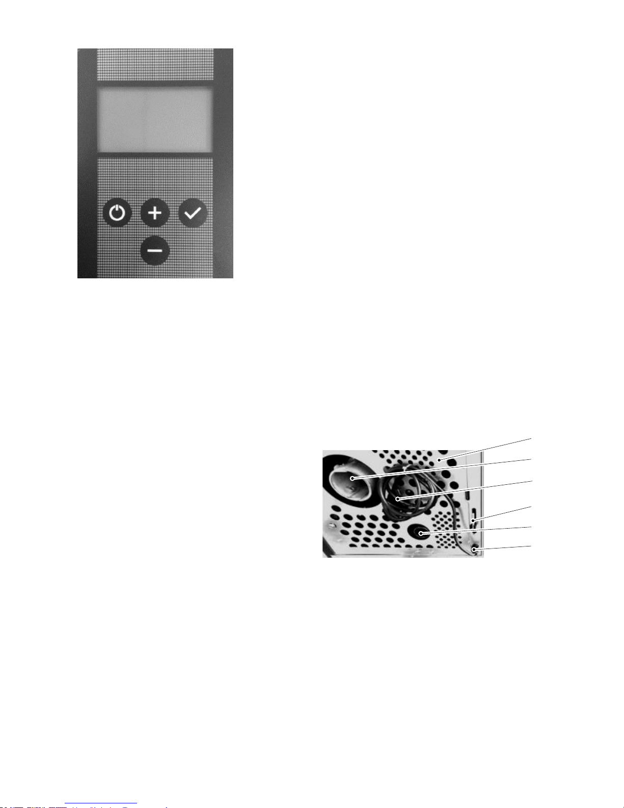
6. Description of operator console keys
6.1. Operator console
As can be seen in the figure, the display is divided into
five areas.
6.2. Description of the symbols
Operating status
Time
Room temperature-target
Room temperature -actual
6.2.1 Display software version after power
connection
As soon as the mains plug is connected, the software
version will be for about 7 seconds on the display.
Software HSP1-V1.12
6.2.2 Setting the language at initial
During initial start after displaying the existing software
version, the adjustment of the desired language.
Procedure:
With the two middle button + and –
select the desired language.
Then confirm "OK" by pressing the
Right button ✔
OK
>deutsch <
english
Language
Language

9
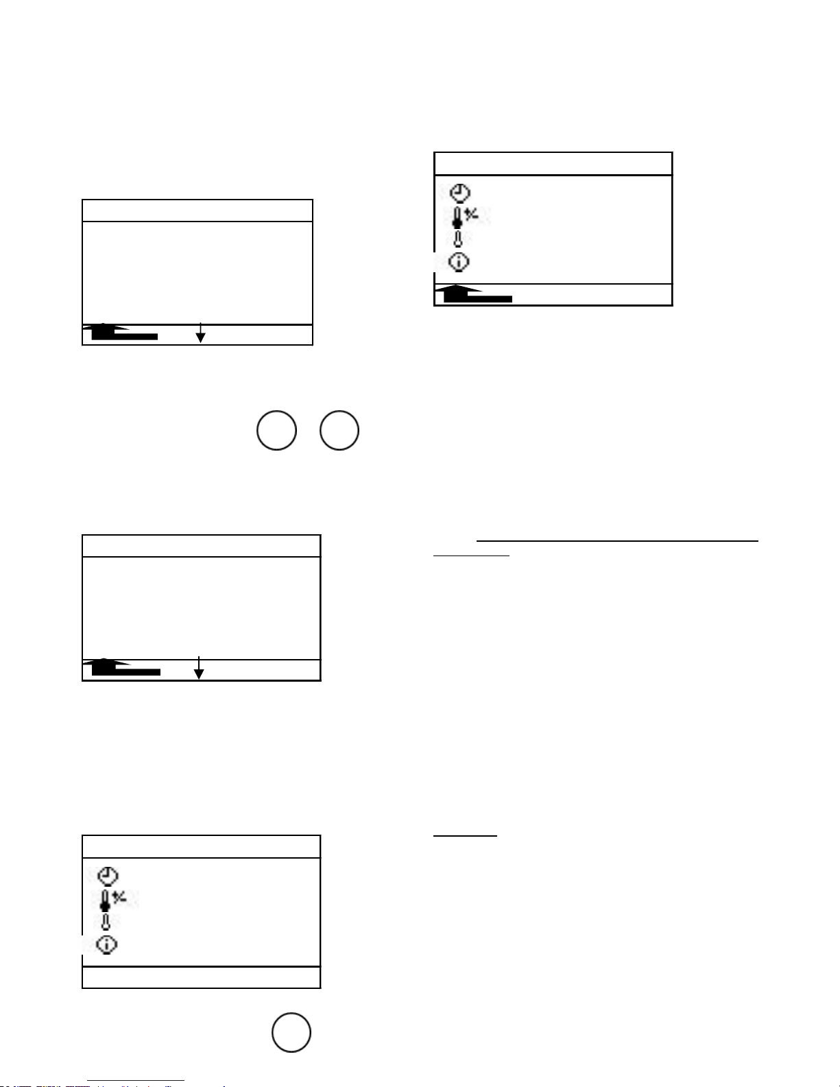
6.3. Standard screen /welcome page
This page will always be displayed when the power plug
is connected to the power outlet.
On Menu
Off
16:18
22°C
23°C
6.3..1 Room temperature display in energy saving
mode
The energy saving mode is activated after a few
minutes. In the energy saving mode, the current room
temperature is shown on the display.
23°C
Note:
By pressing any key, appears after about 3 seconds
the display turn to standard screen.
6.3..2 Setting the operating mode „On“
Procedure:
Press the left button to switch the stove in operation.
Now the boot process begins with the launch zone 1
Off Menu
Start zone 1
08:13
26°C
23°C
6.3..3 Setting target room temperature
Procedure:
By pressing the middle button + and -
you adjust the room temperature. By pressing
the "OK button“ ✔
the set value is stored
+ - OK
OFF
08:15
28°C
23°C
6.4. Main menu
By pressing the right button ✔
the standard screen will appear.
This menu is a scrolldown menu
This menu is shown as a scrolldown menu
OK
Heating curve
ECO-Mode
Main menu
Date/Time
Language english
It contains the entries:
Date/Time
Setting the language
ECO mode setting
Contrast
Heating curve
Software version
Procedure:
By pressing the middle button – and +
you select the desired line.

10
6.4..1 Setting the date and time
+ - O.K.
14:39:28
Date/time
Fr, 13.09.2013
Procedure:
Set the Courser on "Date/Time" and press OK ✔
By pressing the middle button + and –
you adjust the Date . Confirm Date by pressing the OK
button.
Now you can change the time. Confirm Time by
pressing the OK ✔ button.
To exit, press the left button.
6.4..2 Setting the language
l001
OK
>german <
english
Main menu
Language
Procedure:
Set the Courser on "Language" and press OK.
By pressing the middle button + and –
you adjust the language. Confirm by pressing the OK
button.
To exit, press the left button.
6.4..3 Desription – Heating profile
h003
+ - OK
( 2 ) 2
Heating profile
Heating profile
Setting range
Setting range from 1 to 4
Factory setting: 2
The value to be set depends on the size of the room that
is to be heated.
Guideline values:
Room size 20m² - Value 1
Room 25m² - Value 2
Room 30m² - Value 3
Room bigger than 30m² - Value 4
With older stoves a higher value should be set (over 3)
so as to avoid excess condensation in the fireplace.
Procedure:
In the main menu, place the cursor on “Heating profile”
Press the right “OK” key.
Adjust the value with the two middle keys
Then press the right “OK” key.
If you would like to quit this menu screen without saving,
press the left “Back” key.
6.4..4 Desription: ECO Mode
OK
No
>Yes
Main menu
ECO-Mode
The Eco mode means the permanent operation with low
output, if the "real room temperature" is higher than the
set "required room temperature".
If the stove is operated in the ECO operating mode, the
heating output will be decreased after exceeding the
"required room temperature", i.e. the stove is not
switched off, but continues to heat with a "small flame".
When the Eco operating mode is set and the "real room
temperature" of 30°C is exceeded, the Eco mode will be
automatically switched off and the pellet stove will
continue to heat without the Eco mode function.
Warning:
The Eco mode can be reactivated at the controlling unit
in the main menu with the use of "Eco mode - YES".
11
Procedure:
Set the cursor to the "ECO mode" in the main menu.
Press the right "OK" push-button.
Change the setting with the use of both middle pushbuttons.
Then press the right "OK" push-button.
6.4..5 Desription – Display brightness - contrast
setting
OK
Heating profile
Contrast
Main menu
Date/time
Language english
Procedure:
Set the Courser on "Contrast" and press OK.
By pressing the middle button + and – you
adjust the Contrast.
Confirm by pressing the OK button.
To exit, press the left button.
6.4..6 Software Version
Info Software
SW-Version: HSP1-V1.12
Test date: 2014-02-11
Procedure:
Set the Courser on "SW-Version" and press OK.
The current version is displayed.
To exit, press the left button.
6.4..7 Fault screen (top field in the display)
On Quit.
+++ Disturbance +++
F018
16:18
26°C
23°C
Procedure:
Press "Quit" with the right button ✔ and the error
can be confirmed.
Look point 11 on page 22
6.4..8 Description – Key lock (child-safe)
+ - Menu
Aus
08:15
28°C
23°C
Activating the key lock:
Hold the Menu key down for about 10 seconds
until “Key lock activated” appears on the display.
Deactivating the key lock:
Hold the Menu key down for about 10 seconds
until “Key lock activated” is no longer shown on
the display.
7. Operating the pellet stove
The pellet stove may only be heated by adults. Make
sure that children are never left alone with the pellet
stove. (Do not leave the pellet stove unsupervised for a
long period). The pellet stove may only be used in
accordance with these operating instructions.
Please observe the safety instructions set out in Section
2.
7.1. Fuel
The pellet stove may only be operated with “pellet” fuel.
With this fuel you have chosen CO2-neutral heating for
your home.
Pellets are made from wood waste from sawmills and
planing works and from wood collected from forestry
businesses. These raw materials are therefore of 100%
natural origin and are ground, dried and pressed into
“pellet” fuel without the addition of binding agents.
This fuel is standardised (e.g. DINplus, ÖNorm M 7135,
ENplus-A1.).
Important: Your HAAS+SOHN Pelletto pellet stove may
only be operated with standardised wood pellets with a 6
mm diameter.
You can identify good quality wood pellets by eye by:
smooth, shiny surface, uniform length, little dust. Wood
pellets of lower quality are characterised by: Lengthwise
and crosswise cracks, a high proportion of dust, different
lengths. Precise quality features may however only be
identified with suitable technical analysis equipment.

12
A simple quality test: Put a few wood pellets in a glass of
water:
Good quality: Pellets sink
Lower quality: Pellets float.
The use of lower-quality or unauthorised fuel adversely
affects the operation of your pellet stove and may in
addition lead to the lapse of the guarantee and the
associated product liability. Unauthorised fuels include
woodchips, straw and maize. Burning wood pellets of
poor quality leads to shortening of the cleaning intervals
and to increased fuel consumption, so the pellet tank
has to be filled more frequently.
Wood pellets are packed in plastic or paper sacks. To
ensure problem-free combustion of the wood pellets it is
necessary to dry the fuel as much as possible and to
transport and store it free from dirt. On contact with
moisture, pellets swell considerably.
When filling the storage container with wood pellets,
make sure that the pellet sacks do not come into contact
with the hot surfaces of the stove.
Two kilograms of wood pellets have about the same
energy content as a litre of “extra light heating oil.” In
terms of volume, 3 m3 of wood pellets are equivalent to
about 1,000 litres of heating oil. Variations in heat output
by the pellet stove are caused not only by the quality of
the pellets but also by the raw material of the wood (type
of wood).
7.2. Commissioning your pellet stove
The materials making up your pellet stove must
gradually get used to the heat generation. By careful
warming up you avoid cracks in the combustion
chamber plates, damage to the paintwork and warping
of materials. So do not set the target temperature too
high on the control unit (about 1.5°C to 2°C higher than
the current room temperature).
Before commissioning, remove any stickers and
any accessories from the pellet tank and the
combustion chamber.
Check that the combustion chamber cladding is
attached to its fastenings. (This might have
slipped out of its position as a result of the
transportation or installation of the stove).
Check that the combustion pot fits perfectly in its
frame.
Close the combustion chamber door.
Fill the storage container with standard wood
pellets (Ø 6 mm).
Insert the mains cable.
Once the toggle switch has been set to ON, the
control unit commences initialisation. This
process takes a few seconds.
After initialisation, the Information screen
appears – press the right key (Menu) – move
cursor to Operating mode – press the right key
(Select) – select the desired operating mode
with the cursor – press the right key (Save).
Tip!!
Only when commissioning, place about 30
pellets in the burner. This will speed up the
ignition process.
General:
If the ignition phase could not be successfully
run i.e. no flame generation or the required
temperature could not be reached at the flue
gas thermosensor, then a safety shutdown is
initiated and an error message generated (“Ignition
phase target temp. flue gas not reached – check burner
– date and time”).
Note: Any smoke generation caused by further
drying of the paint stops after a short while. Please
properly ventilate the room where the stove is
installed. However, the paint does not contain any
toxic vapours.
8. Cleaning and maintenance work
The functioning of your device depends to a large extent
on regular expert maintenance. Because of the ash
accumulation resulting from the combustion of wood
pellets, constantly recurring cleaning and maintenance
work needs to be carried out. This will permit operation
to be as trouble-free as possible.
The frequency of maintenance in turn depends to a large
extent on the pellet quality (ash content). Quality pellets
have a low ash content of about 0.2-0.3%. However, if
the ash content is higher (0.5% and over), the interval
from maintenance to maintenance is reduced and the
accumulation of ash increases by 2 or 3 times. This
results in lower heat output and an increased fan
rotation speed. We therefore recommend
checking and/or cleaning the flue gas passes
after 1,000 kg of pellets at the latest. (See
Figure 8 a+d).
Attention!
Devices that are not maintained in accordance with
our specifications must not be operated. Failure to
observe this point will invalidate all guarantee
claims.
As soon as you detect ash and clinker deposits in the
cold combustion pot, it must be cleaned. (See Figures 5
+6). If this is not done, the clinker will continue to
accumulate. Then the device will no longer be able to
ignite properly. Pellets can pile up in the combustion pot.
In extreme cases, this can reach all the way back to the
pellet chute. Backfire in the pellet container and
smouldering in the pellet tank might possibly result.
This will destroy your device and is not covered in
your guarantee.
Attention!
Before starting any cleaning work, the stove must be
cool down and set to "Off"! Once the cleaning work
is completed, the correct operating status of the
device must be re-established: Put the combustion
pot in correctly, close the combustion chamber
door.

13
8.1. Cleaning the surface
Dirt on the upper surface of the stove may be cleaned
off with a damp cloth or if necessary with mild soapy
water. You are advised against using corrosive cleaning
agents and solvents since these might damage the
surfaces.
8.2. Cleaning the glass panel
To clean the viewing panel, you must first open the
stove door. Dirt on the glass panel can be removed with
a glass cleaner or with a damp sponge on which you
have sprinkled some of the wood ash present.
(Environmentally friendly).
Cleaning the glass panel may only be done with a
cooled down stove in the OFF operating mode.
8.3. Clean combustion chamber” function
instruction
Die The display on the operator console starts flashing.
(The backlighting switches on and off and the “Clean
combustion chamber” instruction appears).
The instruction to clean the combustion chamber refers
not just to the cleaning of the burner but also to the
cleaning of the entire combustion chamber with an ash
vacuum cleaner.
The process of the “Clean combustion chamber”
function looks like this:
The entire combustion chamber is to be cleaned with an
ash vacuum cleaner at intervals of no longer than 30
operating hours.
The process of the “Clean combustion chamber”
function looks like this:
The entire combustion chamber is to be cleaned with an
ash vacuum cleaner at intervals of no longer than 30
operating hours.
However, this instruction to clean the combustion
chamber (display flashing) does not trigger an error
message during Heating mode. But after the display has
started flashing, if the stove switches
back to “Standby” mode, the stove can no longer be
automatically ignited before the combustion chamber
has been cleaned.
To clean the combustion chamber, the stove has to be
switched to “Off” operating status.
If the combustion chamber is now cleaned, then the
“Clean combustion chamber” error message will
thereafter be cleared automatically. A precondition for
the automatic clearance of this error message is that the
combustion chamber door is open for longer than 60
seconds in “Off” operating status. This time is required
for cleaning the combustion chamber including the
burner thoroughly with an ash vacuum cleaner.
If the door is open longer than 60 seconds in “Off”
operating status, then the operating hours counter,
which is responsible for the “Clean combustion
chamber” instruction, is automatically reset to zero.
This reset of the operating hours counter occurs even if
the cleaning of the combustion chamber is performed
before the 30 operating hours have run provided that the
stove is in “Off” operating status and the door is open for
longer than 60 seconds during cleaning.
8.4. Cleaning the combustion pot -weekly
During operation, deposits may form in the combustion
pot. How quickly the combustion pot becomes dirty
depends solely on fuel quality. The deposits or
encrustations must be removed from time to time.
Cleaning the combustion pot may only be done with a
cooled down stove in “OFF” operating mode. Otherwise
there is a risk of burns!
To this end the combustion pot must be removed from
the stove. Once the combustion pot has been removed,
any residual ash that is in the stove underneath the
combustion pot must also be removed.
After cleaning, the combustion pot is to be put back into
the right position in the burner seat. Check the correct
seating of the combustion pot again so as to avoid poor
seals.
Figure 5: Burner dirty
Figure 6: Burner clean
The cleaning intervals for the combustion pot and the
glass panel depend directly on the quality of the wood
pellets (high ash content) and may vary between a few
hours of combustion and several days.
14
2
1
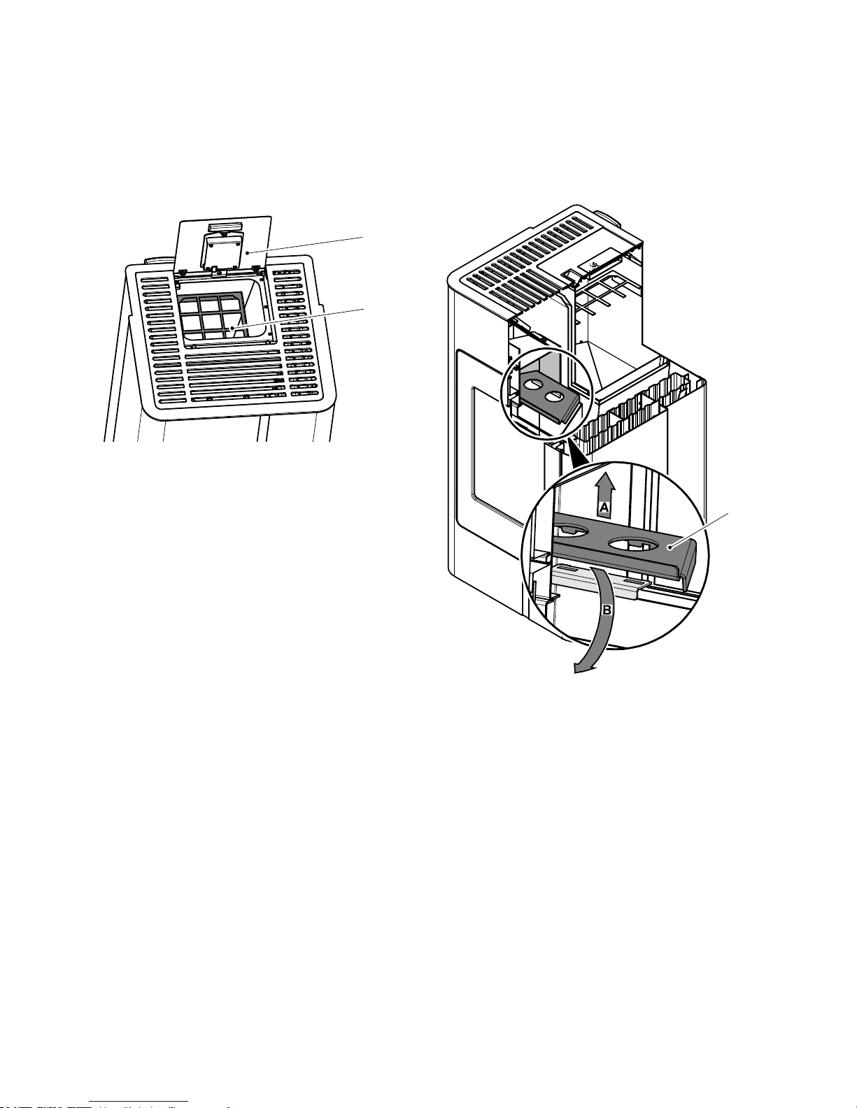
8.5. Cleaning the pellet container - annual
maintenance
Heat the pellet stove until the storage tank is completely
empty. Then the protective grille (1) in the pellet tank
may be removed. Then clean the tank and the intake of
the screw conveyor housing with a vacuum cleaner.
After cleaning, it is essential to put back the protective
grille. When doing this, make sure that no screws fall
into the pellet tank so as to avoid consequential damage
to the screw conveyor.
Figure 7: Pellet tank
Protective grille (1)
Tank cover (2)
8.6. Cleaning the flue gas passes - annual
maintenance
First pull the stove away from the wall so as to create
enough room to work at the back.
To clean the flue gas passes, proceed as follows:
Disconnect the flue baffle (1) from the guide by lifting it.
Draw the right cladding (2) down out of the guide and
place it down in the ash space. Then the flue baffle can
be removed and the upper part of the combustion
chamber can be cleaned. (See Figure 8a).
Figure 8a: Removing the flue baffle
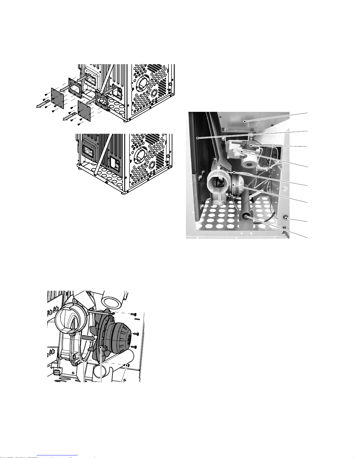
Then remove the right side wall. This is fixed with
screws (1) at the back and at the front with 3 connectors.
Remove the screws from the back and pull the side wall
off sideways. (See Figure 8b+8C).
1
3x

15
2x
2x
3B
1 2
3A3B
3A
3B
Figure 8b: Tilt out the front part
16
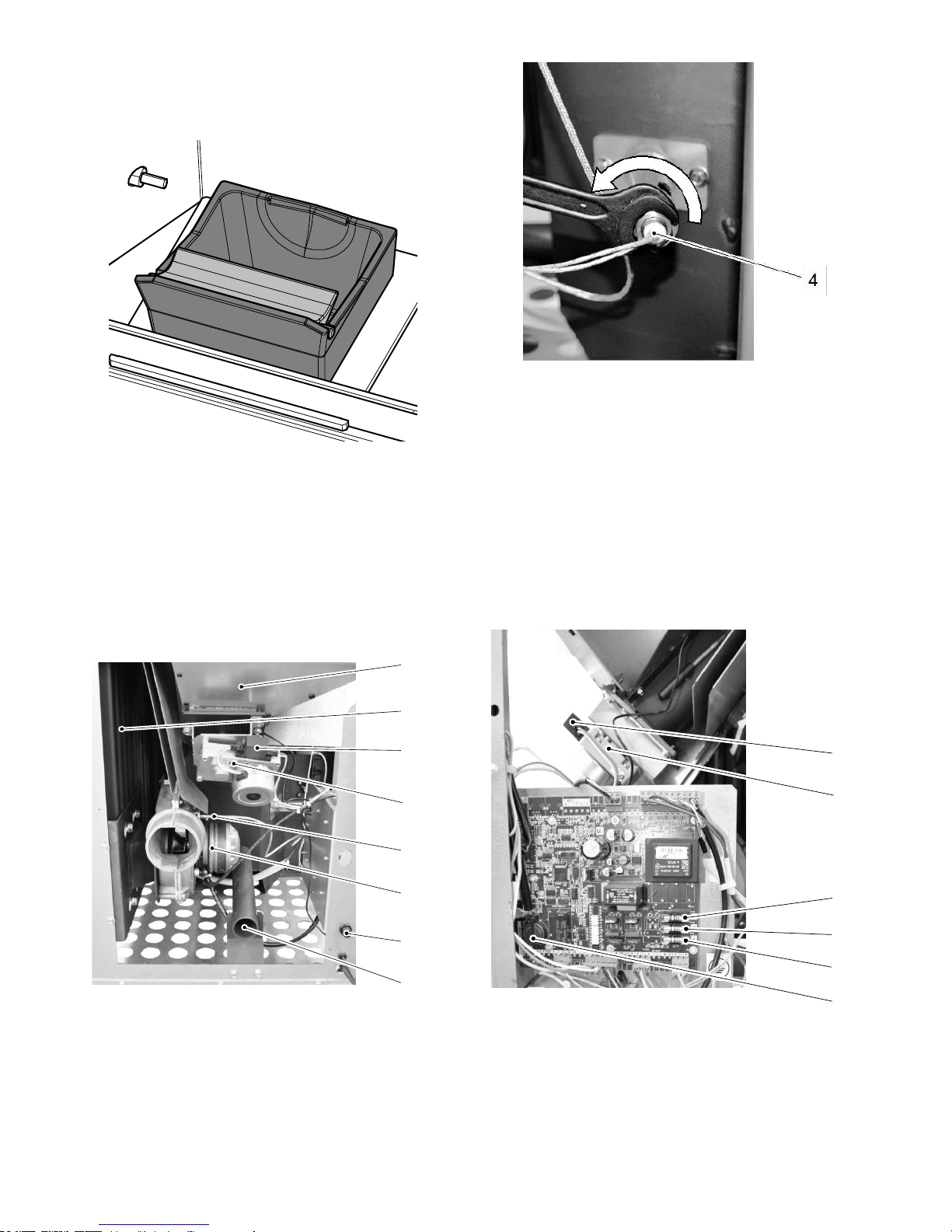
Undo the screws and remove both the covers of the
openings. Tilt out the front part (see Fig. 8b, detail 3A)
After completion of the cleaning make sure that
when putting back the covers, the seals are seated
in the right positions. It is essential to replace
defective seals.
Figure 8d: Cleaning covers
Figure 8e: Cleaning covers open
8.7. Cleaning the induced draught housing and fan
This housing is made accessible for cleaning by undoing
the 4 nuts shown in Figure 9. (See arrows).
Remove the induced draught motor by pulling it out.
Now clean the flue gas passes, the induced draught fan
and the flue tubes with a brush and an ash vacuum
cleaner.
Then reassemble the components in reverse order.
Make sure that the seal is seated in the right position
again. It is essential to replace defective seals.
Make sure of the electrical connections on the fan motor
and their correct positions.
Figure 9: Induced draught fan
1 = Screw
2 = Blower motor
3 = Seal
9. Description of the components
9.1. Storage container (pellet tank)
17 kg of wood pellets can be stored in the storage
container. This quantity permits constant operation for
up to 30 hours.
9.2. Screw conveyor motor / screw conveyor
The screw conveyor motor drives the screw conveyor.
This delivers the wood pellets from the storage container
to the combustion chamber (combustion pot). The screw
conveyor motor’s rotation speed is regulated and it
therefore delivers the required supply quantity to the
modular heat output (2.5 kW to 8 kW).
Figure 10: Screw conveyor motor
1 = Screw conveyor motor
2 = Condenser
3 = Thermosensor, flue gas
4 = Induced draught fan
5 = Overheat cutout
6 = Heat exchanger
7 = Pellet tank
8 = Outside air connection
3 2 1
8
2
1
3
4
5
7
6
17
9.3. Combustion pot with tray:
The combustion pot is made of high-grade cast iron.
The special design of the combustion pot guarantees
clean and extremely efficient combustion of the wood
pellets.
Figure 11: Combustion pot correctly installed
9.4. Electric ignition
The built-in electric ignition is made of stainless steel
(see Figures 13+14) and generates the ignition
temperature required to ignite the wood pellets. The
period during which ignition is activated depends on how
quickly the required flame temperature is reached so
that the system can switch from the Ignition phase to
Heating mode. The average ignition glow time is
depending on pellet quality.
Figure 12: Electrical components
1 = Flame temperature sensor
2 = Overheat cutout
3 = Bottom temperature sensor
4 = Ignition
5 = Screw conveyor motor
6 = Control unit
7 = Backup battery
Figure 13: Stainless steel ignition
9.5. Control unit
The microprocessor control unit ensures safe,
automatic operation of the pellet stove. The control unit
controls the interaction of the components e.g. induced
draught fan, screw conveyor motor, flame temperature
sensor, room temperature sensor etc..
The pellet stove’s electrical fuses are incorporated into
the control unit.
To change these fuses you must remove the left side
wall.
Figure 14:
1. Screw conveyor motor
2. Condenser, screw conveyor motor
3. Fuse T 0,315A
4. Fuses T 3,15A
5. Backup battery
8
2
1
3
4
5
7
6
2
1
4
5
4
3
18
9.6. Operator console
Figure 15: Operator console
9.6..1 Backlighting
The backlighting of the display is switched off 5
minutes after the operator console was last
operated.
9.6..2 Activating the backlighting
The backlighting is switched on by pressing any
key. It is only after the backlighting is activated that
the function keys are active.
The backlighting is also activated by any error
message generated.
9.7. Induced draught fan with rotation speed
feedback
The induced draught fan generates low pressure in
the combustion chamber and thereby supplies the
required volume of air for combustion to the
combustion chamber or through the combustion
pot.
The induced draught fan is equipped with rotation
speed feedback. This permits detection of any
difference between the target and actual operating
status and countermeasures to be taken or, in the
case of greater differences, permits the stove to be
shut down (safety shutdown).
9.8. Flame or combustion chamber temperature
sensor (combustion chamber thermosensor)
The flame temperature is measured in “Heating
mode” operating mode.
The flame temperature measured is an indicator of
the energy level in the grate and hence the basis of
the air volume required for the combustion of the
energy level located in the grate.
Here the ACTUAL flame temperature is compared
with the TARGET in combination with the processorregulated control unit and the appropriate combustion
air volume required for the combustion of the energy
level in the grate is supplied by means of the induced
draught fan.
9.9. Flue gas thermosensor
The flue gas thermosensor is located on the housing
of the induced draught fan and protrudes into the flue
gas duct across the direction of the flow of the flue
gas, where the flue gas flows around it, and thus
measures its temperature and temperature change.
(See Figure 10).
With the thermosensor, the temperature and its
change can be measured directly (accurate to about
2ºC) in the flue gas and so be accessed for the
control unit and regulation.
9.10. Room temperature sensor
The room temperature sensor measures the
ACTUAL room temperature in the area of the
stove.
The room temperature sensor is an instrument for
the TARGET – ACTUAL comparison between the
TARGET room temperature and the ACTUAL room
temperature and is therefore the basis for the
specification of the required heat output for the
stove.
Figure 16:
1 = Mains cable
2 = OC overheat cutout
3 = temperature sensor
4 = Flue elbow 80 mm
5 = Outside air connection 40 mm
6 = Bottom of back wall
6
1
3
5
2
4

19
9.11. OC – Overheat cutout
The overheat cutout sensor is located on the
screw conveyor tube. When a certain temperature
is reached, the OC is triggered independently of the
control unit and it cuts the stove off from the
electricity supply. (Thermo protection).
9.12. Combustion chamber cladding
The combustion chamber is clad on its three
casing surfaces, the left side wall, the right side
wall and the back wall with the material sheet steel.
Figure 17 : Combustion chamber
1 = Flame temperature sensor
2 = Bottom temperature sensor
3 = Pellet chute
4 = Combustion pot
5 = Combustion tray
6 = Door contact switch
9.13. Flue tube connection
The diameter of the flue elbow is 80 mm. The flue
tube must be connected to the fireplace in
accordance with official regulations. For questions
in connection with this, please contact your local
chimneysweep. Because of the way the pellet
stove works with a combustion air fan, high
pressure is generated at the flue gas outlet and
possibly in the fireplace. This means that the flue
gas pipes must be designed to be gas-tight as far
as their entry into the fireplace.
9.14. Mains cable and master switch
Important! The electricity supply to the pellet stove
must always be present! No time switches or other
electric switches may be inserted in or before the
stove’s mains cable. Otherwise your pellet stove
may suffer damage. The master switch for your
pellet stove is located next to the mains cable
socket.
Figure 18:
1. Room temperature sensor (output)
2. Mains cable
3. OC (overheat cutout)
1
2
3
1
2
3
4
5
6
20
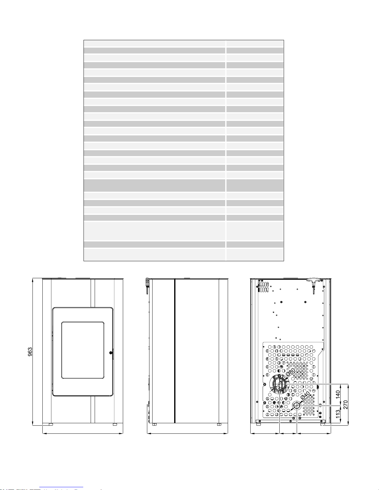
10. Technical data
HSP 2.17
Heat output range:
1.8 – 8.2 kW
Nominal heat output
8.0 kW
Height:
963 mm
Width:
522 mm
Depth:
524 mm
Weight:
86
Diameter of flue elbow:
80 mm
Flue gas temperature
161°C
Minimum supply pressure:
6 Pa
Flue gas flow rate in g/s
-/6.0
CO level in flue gas (%) (min./max.)
0,007/0,1%
Efficiency:
90.4/97.2%
CO level in flue gas:
88/125 mg/m³
NOx level in flue gas:
146/- mg/m³
OGC level in flue gas:
3/6 mg/m³
Proportion of dust in flue gas:
5/- mg/ m³
Contents of storage container (pellet tank):
about 17 kg
Duration of burn with one charge (min./max.):
about 10 hrs / 30 hrs
Permitted fuel: Low-dust wood pellets to Ö-Norm (Ecostandard) M 7135, DIN 51731, EN 14961-2
Diameter: 6 mm,
Length: max. 30 mm
Room heating capacity to Ö-Norm M 7521:
max. 230 m
3
Room heating cap’y to DIN 18893, constant heating:
250m3/145m3/98m3
Room heating cap’y to DIN 18893, timed heating:
165m3/95m3/65m3
Electricity supply:
230 V (50 Hz)
Electricity supply input (min./max.)
in normal operation:
Electric ignition (for max. 15 minutes on ignition):
30 to 50 W
400 W
Electronics fuses: (F3)
T 0.315 A, 250 V
Fuses for the ignition, screw conveyor motor, induced
draught, (F1,) (F2 reserve)
T 3,15 A, 250 V
Figure 19: Dimensions of HSP 2.17
522 524 221189 112

21
11. Faults, causes, correction
You can correct simple faults yourself with the following guide. For further information please
consult your specialist dealer.
Attention! All devices are equipped with a large number of safety devices. If a fault occurs, you
will be shown this on the display.
In the event of a fault, leave the mains plug in so that the internal safety functions can
continue to operate fully. Do not pull out the mains plug until you are about to work on the cold
device.
11.1. Error messages on the display
Error number1
Cause:
OC triggered because of overheating
Or fuse ( F1 ) in the central unit is
defective
Correction:
Change fuse ( F 1 )
If the OC has been triggered, you must
contact the service engineer
Error 2
Cause:
The transition temperature from the
Ignition phase to Heating mode was not
reached.
Burner dirty
Ignition cartridge is not glowing
Correction:
Check pellet stock
Clean burner
Check that the chute between the burner
and the screw conveyor is clear
Contact the service engineer
Error number 3
Cause:
The automatic fuel reduction has initiated
a safety shutdown
Dirty heat exchanger
Correction:
Set the heating profile as description
Room temperature sensor is on the floor
or on the wall – hang the sensor free
cleaning the flue gas passes.
Contact the service engineer
Error number 5
Cause:
Flue gas temperature is starting to fall
rapidly despite maximum heat output for
a long period
The following circumstances might lead to this:
No pellets present
The screw conveyor is not rotating, it is
jammed, the screw conveyor motor is
defective or the chute is not clear
The required combustion air cannot be
supplied to the stove e.g. via a vapour
extractor hood that is located in the
vicinity of the installation site and
switched on.
Burner dirty
Suction filter dirty
Room too airtight – required combustion
air cannot be replenished in the room
Poor seals on the pellet stove (door,
seals)
Flame temperature sensor wrong
Flue gas temperature wrong
Correction
Check pellet stock
Check that the chute between the pellet
tank and the burner is clear.
Clean the burner and suction filter
Check whether there is a vapour
extractor hood present and in operation
Make sure for instance that a window is
left open a crack to supply the required
combustion air
Contact the service engineer

22
Error number 6 or 9
Cause:
The door is open for longer than 1 minute
during operation
The damper at the bottom of the door is
not in the right position
Cable broken in the electric wiring to the
door contact switch
The connector has come out on the door
contact switch or on the central unit
Correction:
Close the door
Move the damper at the bottom of the
door to the right position so that the
switch is operated when the door is
closed
Check door contact switch, cable and
connector
Error number 7
Cause:
Flue gas temperature sensor defective or
not connected
Correction
Contact the service engineer
Error number 8
Cause:
Flue gas temperature sensor defective
Correction:
Contact the service engineer
Error number 11
Cause:
Room temperature sensor defective or
not connected
Correction:
Contact the service engineer
Error number 12
Cause:
Room temperature sensor defective
Correction:
Contact the service engineer
Error number 15
Cause:
The induced draught fan is not
running at the correct rotation
speed
The following circumstances might lead to this:
Induced draught fan defective
Connection cable from the rotation speed
sensor (Hallsensor) is broken or poor
contact in the connector on this
connection cable
Electricity supply to the fan motor
interrupted
Correction:
Contact the service engineer
Error number 17
Cause:
The connection between the central unit
and the operator console is interrupted.
The following circumstances might lead to this:
Connection cable is not connected to the
operator console or to the central unit
Connection cable is damaged
Correction:
Check that the connection cable is
connected to both units, the operator
console and the central unit.
Contact the service engineer
Error number 18
Cause:
A safety shutdown was triggered after a
power cut
Correction:
Clear the fault on the operator console
and restart the device
Error number 21
Cause:
Temperature fell below the minimum
temperature in Heating mode operating
status
The following circumstances might lead to this:
No pellets present
The screw conveyor is not rotating, it is
jammed, the screw conveyor motor is
defective or the chute is not clear

23
The required combustion air cannot be
supplied to the stove e.g. via a vapour
extractor hood that is located in the
vicinity of the installation site and is
switched on.
Room too airtight – required combustion
air cannot be replenished in the room
Suction filter dirty
Burner dirty
Poor seals on the pellet stove (door,
seals)
Flame temperature sensor defective
Flue gas temperature sensor defective
Correction:
Refill pellets
Check that the chute between the pellet
tank and the burner is clear.
Clean the burner and suction filter.
Check whether there is a vapour
extractor hood present and whether it is
in operation
Make sure for instance that a window is
left open a crack to supply the required
combustion air
Contact the service engineer
Error number 22
Cause:
The highest permitted flue gas
temperature was exceeded
The following circumstances might lead to this:
Too much fuel is being supplied to the
burner
Flue gas temperature sensor defective
Correction:
Contact the service engineer
Error number 23
Cause:
Flame temperature sensor defective or
not connected
Correction:
Contact the service engineer
Error number 24
Cause:
Bottom flame temperature sensor
defective or not connected
Correction:
Contact the service engineer
Error number 26
Cause:
Burner dirty, pellets have low calorific
value.
No pellets present
Correction:
Clean burner, if necessary change pellet
type
Refill pellets
Error number 27
Cause:
Dirty • burner / combustion chamber
Wrong position of burning pot
leaking tank or door
Correction:
Clean burner / combustion chamber
Check position of burning pot
Check the seal on the fuel cap and door
Error number 28
Cause:
Dirty • burner / combustion chamber
Correction:
Clean burner / combustion chamber
Backup battery empty
Cause:
Backup battery of the central unit is
empty
Backup battery not connected
Correction:
Check connection
Replace backup battery
Contact the service engineer

24
11.2. General faults
Fault:
Cause:
Correction:
Stove will not ignite
1. The set target room
temperature is lower than the
current room temperature (actual
temperature); the “STANDBY”
symbol appears on the display
Increase the target temperature.
2. Storage container is empty
Refill storage container.
3. Excess pressure in the fireplace
system
Open any fireplace vents, remove any dirt
from the fireplace or flue tube
4. Electric ignition is defective
Replace ignition fuse (in the control unit) or
call in the service engineer
5. Electricity supply is interrupted
Put in the mains cable, check fuse (in the
control unit, see Figure 14), check fuse in the
distribution box
6. Error message “OC triggered,
check burner”
Replace fuse F1 in the control unit (T3, 15A)
7. Fuse defective
Replace fuse F3 in the control unit
(T0, 315 A)
No display showing
1. Loose or defective connection
cable between operator console
and control unit
Check plugs and sockets, otherwise call in
the service engineer
Fire burns with a tall
yellow flame;
wood pellets piling up in
the combustion pot
and/or the viewing
panel is excessively
sooty
1. The combustion air supply to
the combustion pot is blocked by
ash deposits.
Turn off the stove and let it cool down.
Remove the combustion pot from its support
and clean the air holes
2. Combustion pot is not correctly
seated
Make sure that the combustion pot is
correctly seated.
3. Poor quality fuel
Use only standard wood pellets. Make sure
that the fuel is dry and cannot absorb any
moisture during storage.
4. Seals on the combustion
chamber door or on the cleaning
covers are defective
Call in the service engineer
5 Flue gas passes or flue tubes
partly blocked with fly ash
Clean flue gas passes and flue tubes

25
Fire goes out
1. Storage container is empty
Refill storage container
2. The combustion air supply in
the combustion pot is blocked by
ash deposits
Clean burner
3. Pellet container contains too
much dust
Empty pellet container and clean screw
conveyor channel with vacuum cleaner
4. Screw conveyor jamming
1. Pull out the mains plug and move the
screw conveyor motor back and forth,
otherwise 2. empty pellet container and clean
screw conveyor channel with vacuum
cleaner, otherwise 3. call in the service
engineer
5. Flue gas fan defective
Call in the service engineer
Pellet stove shuts off
after about 30 minutes
1. Flue gases have not reached
operating temperature
Check whether there are enough wood
pellets in the combustion pot. Press the
ignition button again.
2. Burner displaced
Clean burner
Flue gas escaping
1. Power cut
Ventilate room
2. Flue tubes or chimney
(fireplace) very dirty
Clean flue tube or chimney (fireplace)
12. Type plate: Symbol
HAAS + SOHN OFENTECHNIK GMBH
Urstein Nord 67, A-5412 Puch
Pellet-Kaminofen
Typenbezeichnung:
713.07
Variante:
HSP 2.17
Wärmeleistungsbereich:
1,8 - 8,2 kW
Nennwärmeleistung
8,0 kW
Zugelassener Brennstoff:
Holzpellets Ø 6mm (DINplus, ÖNorm M 7135, ENplus-A1),
Prüfstellenkennziffer: 1625
Registrier Nr.
RRF-85 13 3375
Bauart: EN 14785 und DIN 18897-1
CO bez.auf 13% O2 NWL
CO bez.auf 13% O2 Teillast
Staub bez.auf 13% O2: 3,7 mg/Nm3
0,01%
0,02%
Wirkungsgrad:
90,10%
97,00%
Mindestabstände zu brennbaren Bauteilen:
seitlich:
10 cm
hinten:
5 cm
vorne im
Strahlungsbereich:
70 cm
Versorgungsspannung:
230 V (50 Hz)
Elektrische Leistungsaufnahme:
Heizphase:
30-50 W
Zündphase:
400W
Abgastemperatur am Stutzen: 184°C
Bedienungsanleitung beachten!
Prüf Nr. VKF:
Anbringungsjahr: 2014
Herstellnummer: 91405471200101
Bei Raumluftbetrieb ist die Mehrfachbelegung des Schornsteins zulässig!

26
Figures 21: Replacement parts HSP 2.17
Figures 22: Replacement parts HSP 2.17
32
31
20
15
16
35
10
12
22
38
39
21
32
31
25
36
37
1
8
9
2
41
43
5a
6a
6b
4b
11
26
24
34
23
33
30
28
29
27
23
34
47
4a
4b
46
45
44
43

27
13. Replacement parts list
HSP 2.17
Front plate cast left anthracite
4a
0571307005120
Front plate cast right anthracite
4b
0571307005130
Complete combustion chamber door black
10
0571207005300
Door hinge cast black
11
0571207005034
Glass panel
12
0571207005301
Sealing strip, glass panel 10x4
0040210040005
Sealing strip, combustion chamber door
0040300110005
Tank cover cast iron grey
1
0571307005140
Cover hinge pins
9
0030110500181
Front plate cast left anthracite
4a
-
Front plate cast right anthracite
4b
-
Side wall rear left black
6a
0571307005111
Side wall rear right black
6b
0571307005110
Protective grille
2
0571207005921
Cover plate black
41
0571307005150
Combustion pot
15
0571207005751
Combustion tray
16
-
Pellet chute
20
0571207005120
Draught baffle plate
21
0571207005701
Allen key 6 mm
43
9001700060005
Stand
22
0561008009641
Mains cable
23
0089500990000
Cable screw conveyor motor with capacitor
- Ignition 350 W
25
0561008005202
OC
24
0571207005840
Induced draught fan
26
0571207005820
Screw conveyor motor
27
0089500880005
Screw conveyor
28
0571207005030
Lower screw conveyor bearing
30
0089000340008
Motor plate
29
0571207007080
Bottom temperature sensor
31
0561008005543
Flame temperature sensor
32
0571207007539
Flue gas thermosensor
33
0561008005540
Room temperature sensor
34
0089500390005
Door contact switch
35
0561008006510
Complete control unit
36
0561008005569
Operator console
8
0571207005510
Complete seal set
0571207006030
Seal set for cleaning openings
0561008006041
Backup battery
37
CR2032
Heat exchanger
38
0571207006020
Back wall
39
0571207005971
Holder
44
-
Upper front panel
45
0571307005038
Lower front panel
46
0571307005039
Upper cover
47
0571307005160

28
14. Circuit diagram

29
No.:
Description Cable harness
3
Mains plug / mains filter
5
Electric ignition
6
Screw conveyor motor
7
Induced draught
8/9
OC
35/36
Flue gas temperature sensor
37/38
Flame temperature sensor
39/40
Room temperature sensor
41/42
Bottom flame temperature sensor
43/44
Door contact switch
48-50
Flue gas fan rotation speed
F1
Fuse T 3,15A ignition, induced draught fan, screw conveyor motor
F2
Fuse T 3,15A reserve
F3
Fuse T 0,315A operator console

30
15. Guarantee
General
HAAS + SOHN gives the purchaser a guarantee
within the context of the legislation. The two-year
guarantee period commences on the date of the
actual handover. The invoice is to be submitted as
proof.
Guarantee guidelines
If a defect occurs in your device within the
guarantee period, HAAS + SOHN will correct
(improve) this defect in the shortest possible time
or optionally replace the defective item.
Cancellation of the contract/a price reduction is
excluded in so far as this exclusion does not
conflict with legislation. Only replacement parts
that are expressly authorised or offered by the
manufacturer may be used.
We would like to point out that our customer
service offices are also available on the usual
terms and conditions at any time after the expiry of
the guarantee.
We reserve the right to make technical changes.
HAAS + SOHN gives no guarantee for damage to
or defects in devices or parts there of that have
been caused by:
Changes to the subject of the purchase that are
connected with normal wear and tear (fire clay,
Vermiculite, grate, glass ceramics and seals etc.),
incorrect operation (e.g. overheating),
overloading, neglect and changes without the
consent of HAAS + SOHN are excluded from the
guarantee.
Errors in the installation and connection of the
device, insufficient or too-strong chimney draught,
incorrectly carried out repair work or other, in
particular subsequent, changes to the heating
appliance or flue gas pipework (stove pipe and
chimney),
use of unsuitable fuels, incorrect operation;
overloading the devices (see the manufacturer’s
operating instructions), wear on the parts made of
iron or fire clay directly exposed to the flames, in
so far as they are not covered by the guarantee
(1a), incorrect handling, insufficient care, the use
of unsuitable cleaning agents.
Complaints
Please address any complaints only to your
specialist dealer. Here you must state the type and
manufacturer’s numbers of your stove. You will find
this information on the type plate of the device (on
the back of the device).
Instructions for ordering replacement parts
When ordering replacement parts we would ask
you to state the full type and manufacturer’s
numbers of your pellet stove. You will find this
information on the type plate of the device (inside
the cover of the storage container) and on the first
page of these instructions. If there is no reference
to type or manufacturer’s number in this place,
place enter them there. Then you will always have
all the important information to hand.
Please also note the drawings and tables in these
instructions. Here you will find the correct
descriptions of the required replacement parts.
Attention! The heating appliance must not
be modified!
Only replacement parts that are expressly
authorised or offered by the manufacturer may
be used.
If necessary, please contact your specialist
dealer.

31
We accept no liability for changes made after going to press with these instructions.
We reserve the right to make changes.
Our product range: Oil stoves
Stoves
Pellet stoves
Tile stoves and slow combustion stoves for wood and coal
Slow combustion stoves and auxiliary ranges for wood, coal and oil
Fireplace inserts for wood
Accessories for stoves and fireplaces
Accessories for central oil supply
HAAS+SOHN
Sales in Germany
OFENTECHNIK GMBH
HAAS+SOHN Ofentechnik GmbH
Urstein Nord 67
Zur Dornheck 8
A-5412 Puch
D-35764 Sinn - Fleisbach
Email: office@haassohn.com
Email: info@haassohn.com
http://www.haassohn.com
 Loading...