

Haas+Sohn HRT 160, HRT 160SP, HRT 210SP, HRT 210, HRT 310SP Operator's And Service Manual
...
Haas Technical Publications
Manual_Archive_Cover_Page Rev A
any other party automatically voids the factory warranty.
June 6, 2013
HAAS SERVICE AND OPERATOR MANUAL ARCHIVE
HRT Operator Manual 96-5047 RevL English June 2005
• This content is for illustrative purposes.
• Historic machine Service Manuals are posted here to provide information for Haas machine owners.
• Publications are intended for use only with machines built at the time of original publication.
• As machine designs change the content of these publications can become obsolete.
• You should not do mechanical or electrical machine repairs or service procedures unless you are qualied
and knowledgeable about the processes.
• Only authorized personnel with the proper training and certication should do many repair procedures.
WARNING: Some mechanical and electrical service procedures can be
extremely dangerous or life-threatening.
Know your skill level and abilities.
All information herein is provided as a courtesy for Haas machine owners
for reference and illustrative purposes only. Haas Automation cannot be held
responsible for repairs you perform. Only those services and repairs that are
provided by authorized Haas Factory Outlet distributors are guaranteed.
Only an authorized Haas Factory Outlet distributor should service or repair a
Haas machine that is protected by the original factory warranty. Servicing by

Back
1. INTRODUCTION
1.1 D
ESCRIPTION
The HAAS rotary table is a fully automatic, programmable, rotary positioning device. The unit is made up of two
parts: the mechanical table that holds the workpiece and the electronic unit that controls the rotation of the
table. Positioning of the workpiece is accomplished by programming the angular movements into the memory
of the control and then pushing the CYCLE STAR T button on the front panel.
The unit was specifically designed for rapid positioning of parts in secondary operations such as milling,
drilling, and tapping. The device is especially suited to automatic machines such as NC mills and automatic
production machines. The control can be remotely activated by your equipment and does not require human
assistance, resulting in fully automatic operation. Furthermore, one unit can be used on several different
machines, thereby eliminating the need for multiple units.
TABLE
The rotary table can be used in almost all of the applications where a manual rotary table can be used. Positioning of the table is accomplished through a deep-tooth engaging, self-locking worm and worm gear set. The
worm is connected to a AC (DC) servo motor through a timing belt and pulley set. Odd number bolt circles and
uneven hole spacing are easily handled with simple programming. The table is equipped with a pneumatic
brake (HRT 450 uses air over oil). A regular shop air line of approximately 100 PSI is all that is needed to
activate the brake.
The HRT210SHS (Super-High Speed) Table is unique from the other rotary t ables. It has no worm gear set, belt,
or pulleys but uses a “Harmonic Drive” gear. It is directly driven by an AC servo motor and is 6 times faster than
our standard HRT210.
The HRT320FB uses a facegear (Hirth coupling) for extreme indexing accuracy and rigidity . It positions the
platter in multiples of exactly 1° . The platter lifts .070” during indexing and the table positioning is done at full
rapid speed. The HRT320FB cannot be used as a full forth axis.
CONTROL
The rotary table servo control incorporates the latest in high-speed microprocessors and drive technology . The
control was designed using extensive software to replace discrete components, thereby reducing possible
failure areas. This same software also checks out the computer system upon power-up, and alerts you to
component failures. Only one printed circuit board is used to control all major functions.
The optional RS-232 interface can be used to upload, download, enter data, read position, start, and stop motor
operation.
96-5047 rev L June 2005
1

1.2 LIMITATIONS
The control and table are described as a “semi-fourth axis”. This means that the table cannot do simultaneous
interpolation with other axes. Linear moves or spirals can be generated by having an axis of your mill move at
the same time the rotary table moves (see the "Programming" section for details).
1.3 MACHINABLE P ART S IZE
The HRT series was designed for positioning and continuous milling of medium to large size parts. When
selecting a rotary table, the size of a typical workpiece and fixture must be considered and the size of the
rotary table should be matched to the expected loads. As a general rule, the diameter of the part should not
exceed the diameter of the rotary table platter . Also, the combined part and fixture weight should not exceed
the weight of the rotary table. However , these are only guidelines. A part with a diameter larger than the platter
diameter or a long overhung and unsupported part might require that the weight be less than the weight of the
rotary table. Likewise, if the part is well supported (i.e. tailstock or pillow block), and the fixture and support
have less than 0.003" T.I.R, then the weight might be able to be more than the rotary table weight. Common
sense and good fixturing technique will generally make it possible to machine larger parts.
The HRT210SHS Table was designed for lighter size part s which may require numerous tool changes and
indexes, so the speed is important to reduce the cycle time. It has no brake, so this will also be a limiting
factor to the size of the part. Maximum part diameter is 8.00” and maximum part weight should not exceed 40
lbs.
1.4 FEATURES
RIGID DESIGN
Large bearing surfaces support heavy cutting forces on large or small parts.
CLASS 30 GREY IRON
For added damping capacity
QUICK REPLACEMENT CONDUIT
For faster replacement and shorter downtime.
PRE-LOADED ANGULAR CONTACT BEARINGS
For better reliability and less wear.
HARDENED AND PRECISION ROT ARY GROUND PLATTER
Ensures more accurate part machining.
CNC HOBBED WORM GEAR*
For high accuracy.
DEEP TOOTH ENGAGEMENT
For gear set; designed to provide greater accuracy and continuous milling capacity .
ALUMINUM BRONZE WORM GEAR*
For long life.
HARDENED AND GROUND WORM GEAR*
Made from 8620 chromium-nickel-molybdenum steel, hardened to Rc 60.
AIR BRAKE*
Built-in air brake with 100 to 1500 ft.-lb. of holding torque @ 100 PSI. (Except HRT210SHS)
2
96-5047 rev L June 2005

AC SERVO DRIVE*
Closed loop 3.0HP (HA5CHD, HRT 160, HRT 210), 5.0 HP (HRT 310, HRT 450, HRT 600), 1.5 HP (HA5C)
DC SERVO DRIVE
Closed loop 0.5 HP(HRT160, HA5C), or 1.5 HP(HRT210, HRT310, HRT450, HRT600).
V ARIABLE FEED RATES*
V ariable from .001 deg./sec. to 100 deg./sec (100 deg./sec. for HRT160 and HRT320FB, 75 deg./sec. for
HRT210, 60 deg./sec. for HRT310, 50 deg./sec. for HRT450, 40 deg./ sec for HRT600).
RESOLUTION
St andard motor resolution of .001 degrees (.001
0
).
PROGRAMMING
Absolute or incremental programming. Up to 99 different steps can be stored in memory, and each step can be
looped 999 more times. The ease and flexibility of programming the Haas control enables a single unit to serve
you in many ways.
SIMPLE EDITING
Edit a program by simply writing over existing steps, or inserting or deleting a line (or several lines) between
steps, with automatic program line re-numbering.
SUBROUTINES
Allows sequences to be repeated up to 999 times, saving programming time and memory space.
AUTOMA TIC CIRCLE DIVISION
Program a step that automatically divides a circle into any number of equal parts (between 2 and 999).
PROGRAMMABLE P ARAMETERS
Alter many of the basic features by performing your own basic programming.
PROGRAM STORAGE
Store and recall from up to seven dif ferent programs.
MEMORY
A non-volatile memory retains a program even when power is turned off. It also remembers the current spindle
position and step number.
INTERFACING
Most CNC mills can be interfaced with the HRT Series quickly and easily by using a spare M function that
provides a switch-closer as a signal between your mill and the RT.
EMERGENCY STOP/FEED-HOLD
EMERGENCY STOP can be used to feed-hold spindle movement without losing position on restart.
ZERO RETURN
A programmable HOME position returns the spindle to its original starting position from any point.
LINEAR & SPIRAL MILLING
For semi fourth-axis capability .
FAST SET -UPS
All connectors are “quick-disconnect”, ensuring fast and easy set-ups.
ST ANDARD POWER
Operates on 1 15V AC ±5% @ 15 Amps.
96-5047 rev L June 2005
3

OPTIONAL RS-232 INTERF ACE
For computer control of sending and receiving programs.
12-MONTH WARRANTY
Against any defects in materials or workmanship.
SYNTHETIC GEAR OIL
Provides greater worm gear wear protection than conventional gear oils.
*Except HRT210SHS; see below:
FEATURES E XCLUSIVE TO THE HRT210SHS
Harmonic Drive gear set.
3 HP A.C. Servo Motor
V ariable feed rates from .001 deg./sec. to 270 deg./sec. with rapids to 360 deg./sec.
4
96-5047 rev L June 2005

1.5 SPECIFICATIONS
:LEDOM)PS(061TRH)PS(012TRH)PS(013TRHBF023TRH054TRH006TRH
ELDNIPS
)sbl/.tf(euqroTelbaT
CD/CA
).ces/.ged(setardeeF
CD/CA
001/051012/012002/003003523/004083/054
001ot100.CA
08ot100.CD
CD063ot100.
001ot100.CA
06ot100.CD
1
031ot100.0CD
2
06ot100.CA
05ot100.CDylnoces/°08
)sehcni(tuonuReldnipS5000.5000.100.100.5100.5100.
)ni(tuonuRecaFrettalP5000.5000.5000.5000.5000.5000.
).ces-cra(hsalkcaB03
03
1
54
03A/N0303
)sehcni(thgieHretneC100.-/+000.5100.-/+000.6100.-/+000.9100.-/+000.9100.-/+005.11100.-/+005.41
euqroTgnidloHekarB
).sbl/.tf(ISP001@
001
002
2
A/N
005005300510051
GNIXEDNI
ycaruccAgnixednI
).ces/cra(
51-/+
).cescra(ytilibataepeR01nihtiw01nihtiw01nihtiw1-/+01nihtiw01nihtiw
).ged(noituloseR100.100.100.0.1100.100.
).ged(noituloseR.xaM999.999999.999999.9990.999999.999999.999
51-/+
2
03-/+
3
6-/+
51-/+3-/+51-/+51-/+
05ot100.CA
04ot100.CD
05ot100.CA
04ot100.CD
)"ni(aiDraeGmroW7.43.64.94.95.315.31
ROTOM
3,1
PH0.3
)sselhsurB(ovreSCA
)hsurB(ovreSCD
tleBgnimiT(oitaRevirD
)teSyelluPdna
oitaRraeGmroW1:36
noitcudeRraeGlatoT1:621
PH0.3
PH5.0
1:2
0.5/
2
PH
PH5.1
1:2
1
2
1:1
A/N/
1:09
2
A/N
1:081
1
1:09
2
1:05
PH0.5
PH5.1
PH0.5
PH0.5
PH5.1
1:21:21:31:5.3
1:271:271:271:27
1:4411:4411:6121:252
PH0.5
PH5.1
SNOITACIFICEPSGNITAREPO
erusserPriA.xaM
stnemeriuqeRrewoP
noitacirbuL
)BF023TRHrofmuminimisp04(ISP021
spmA51@%5-/+CAV511
lioraegcitehtnys036-CHSliboM
2
lioraegcitehtnys626-CHSliboM
TNEMNORIVNEGNITAREPO
erutarepmeTmumixaM FseergeD001
1
2
3
SH012TRH
SHS012TRH
CS012TRH
96-5047 rev L June 2005
5

1.6 MACHINE D IMENSIONS
MODEL DIMENSIONS
A BCD E F G H J
HRT160 160 mm (6.30") 1.50 5.50 16.20 3.63 5.000 ±0.001 4.50 Ø1.50
HRT 210 210 mm (8.27") 1.75 5.84 17.80 4.63 6.000±0.001 5.25 Ø2.00
HRT210 (Brush) 210 mm (8.27") 1.75 5.84 20.00 4.63 6.000±0.001 5.25 Ø2.00
HRT210SC 210mm (8.27”) 1.75 7.65 17.80 4.63 6.000 +/-.001 7.025 Ø2.00
HRT 310 310 mm (12.20") 2.00 7.82 22.80 6.88 9.000±0.001 7.875 Ø3.25
HRT320FB (*The platter lifts .065” during positioning)
HRT310 (Brush) 310 mm (12.20") 2.00 7.82 24.30 6.88 9.000±0.001 7.875 Ø3.25
HRT450 450 mm (17.72") 2.25 9.00 28.55 9.26 11.500±0.001 9.00 Ø7.50
HRT600 600 mm (23.62') 2.50 9.00 34.82 12.13 14.500"±0.001 9.00 Ø7.50
+0.0005
+0.0005
+0.0005
+0.0005
+0.0005
+0.0005
+0.00
+0.001
10.4
12.4
12.4
12.4
17.7
17.7
22.4
28.4
6
96-5047 rev L June 2005

HRT SP DIMENSIONS
B
A
F
14'
C
G
D
E
WRENCH
ACCESS
0.530” W x 0.50” DP
Front & Rear Tie Down Slots
MODEL DIMENSIONS
A B C D E F G
HRT 160SP 10.80” 12.25” 10.39” 8.63” 5.000” ±0.001” 4.78” 1.500∅ x 6.00 Depth
HRT 210SP 12.28” 13.77” 12.39” 10.64” 6.000” ±0.001” 5.26” 2.000∅ x 7.000 Depth
HRT 310SP 16.26” 17.80” 17.60” 15.90” 9.000” ±0.001” 6.88” 3.250∅ x 9.875 Depth
96-5047 rev L June 2005
7

HRT210SHS MACHINE D IMENSIONS
8
96-5047 rev L June 2005

1.7 OPTIONAL S ERVO C ONTROL B RACKET
Designed to work specifically with the Haas line of CNC mills. This bracket keeps the Servo Control in easy
reach of the operator, allowing for easy programming between the Haas mill and Rotary t able. Contact your
Haas dealer to order. (Haas p art number: SCPB)
Installed Servo Control Bracket
1.8 HAAS T AILSTOCKS
T ailstocks must be properly aligned to the rot ary table before using.
Clean bottom surface of tailstock casting before mounting to mill table. If there are any noticeable burrs or
nicks on the mounting surface, clean them with a deburring stone.
See the Haas tailstock manual (96-5000) for pneumatic tailstock’s operating pressure.
T ailstocks cannot be used with the HR T320FB table.
96-5047 rev L June 2005
9

2.1 GENERAL S ETUP
1. Fill out the warranty card and mail it in. (V ery Important).
2. Place the indexer on your machine. Route the cable from the table such that it avoids tool chang-
ers and table edges. Slack must be provided for your machine's movements. If the cable is cut, the
motor will fail prematurely . Secure the HRT Rot ary Table to your machine’s T-Slot t able as shown
below.
NOTE: The HRT 160, 210, 450, and 600 Rotary Tables can be secured as shown:
1/2-13UNC T-Nuts, Studs,
Remove TopCover
to Access Toe-Clamp
Pockets
Flange nuts and Washers*
2. SETTING UP THE HAAS ROTARY TABLE
Bottom View
of Casting
Clamping Tool
Assembly (2)
1/2-13UNC T-Nuts,Studs,
Flange Nuts, and Washers
*
ToeClamp
Assembly
1/2-13UNC T-Nuts,
Studs, Flange nuts,
and Washers
*
1/4-20UNC
SHCS (4)
Toe-Clamp
Assembly (2)*
*NOTE: Toe-Clamp Fasteners are not supplied. *Standard stud mounting, front and
rear For extra rigidity , use
additional T oe-Clamps.
NOTE: The HRT 310 can be secured as shown:
0.781” Thru
3/4-10UNC X 8”
SHCS (4)
7.875”
1” Req.
Fixture Plate
C’Bore 1.188 X 0.80 DP
1/2-13UNC T-Nuts,
Studs, Flange nuts
and Washers
3. Connect the indexer to run as a full-fourth or semi-fourth axis. See the following figure. For fullfourth axis, the indexer is connected directly to the HAAS mill control at the connector labeled “AAxis”, and is the desired connection.
10
96-5047 rev L June 2005

SEMI-FOURTH AXIS OPERATION
POWER
ServoControl
DEGREES
SERVO
ON
OVER
LOAD
STEP
SCAN
HIGH
LOAD
CYCLE
START
EMERGENCY
STOP
JOG
ZERO
RETURN
CLEAR
DISPLAY
SCAN
ZERO
SET
RUN
PROG
TO MILL
INTERFACE CABLE PORT
ON
POWER
ServoControl
SERVO
ON
STEP
RUNNING
C
Y
C
L
S
E
T
A
R
T
E
M
E
R
G
DEGREES
E
N
C
7
S
Y
TO
P
8
OVER
-
LOAD
0
HIGH
4
J
O
LOAD
G
9
MODE
+
5
RUN
PROG
9
Z
E
R
1
R
O
E
6
T
DISPLAY
U
R
N
2
CLEAR
SCAN
ZERO
SET
3
0
STEP
SCAN
4TH AXIS
-
FULL-FOURTH AXIS OPERATION
4TH AXIS
RS232 PORT OR
SERVO
CONTROLLER
TO MILL
4TH AXIS PORT
Note: Your HAAS mill must have the 4th axis option to run full-fourth and must be
configured as brush or brushless to be compatible with your indexer. Brush
configuration uses one cable and one connection at the A-axis port on the
control. Brushless uses two cables and two connectors at the A-axis port.
(HRT320FB cannot be run directly from a mill)
4. Route the cable over the back of the mill sheetmetal and install the cable clamp. The bottom plate
of the clamp assembly must be removed and discarded before installing the clamp to the mill.
Assemble the clamp to the mill as shown.
49-0001
79-0001
Shipping
Plate
96-5047 rev L June 2005
11

5. If adding an indexer to a Haas mill the settings must be set for the specific table. Refer to the
instructions in the mill manual or call the Haas service department.
6. Semi-Fourth Axis: Secure the servo control in servo pendant bracket (Haas part number SCPB)
as seen at the end of the introduction section.
7. Connect the large black cable from the table to the controller .
CAUTION: Never connect or disconnect this cable with the power on! Instant failure
will result!
8. Semi-Fourth Axis: Connect the AC line cord to a 120V AC grounded recept acle. The cord is a
three-wire ground type, and the ground must be connected. Power is 120VAC. The power service
must supply a minimum of 15 amps continuously . Conduit wire must be 12 gauge or larger and
fused for at least 20 amps. If an extension cord is to be used, use a three-wire ground type and the
ground line must be connected. A void outlets that have large electric motors connected to them.
Use only heavy duty 12 gauge extension cords capable of 20 amp load. Do not exceed a length of
30 feet.
9. Semi-Fourth Axis: Connect the remote interface lines. See “Interfacing to Other equipment”
section.
10. Connect the table to a standard shop air line (120 PSI Max). The line pressure to the brake is not
regulated. Do not exceed the maximum pressure.
NOTE: HAAS recommends the use of an in-line air filter/regulator for all tables. The
air filter will keep contaminates from entering the air solenoid valve.
11. Check the oil level. If it is low, add oil. Use MOBIL SHC-630 synthetic gear oil (V iscosity Grade
ISO 220). For the HRT210SHS use Mobil SHC-626 synthetic gear oil (Viscosity Grade ISO 68).
12. Save the packing materials in case you need to ship the unit.
13. At the end of the workday or shift, it is important to clean the rotary table. The table should be free
of any chips or grime. Clean with a chip brush and apply a coat of a rust preventative.
CAUTION! Do not use air gun around front or rear seals. Chips may damage seal if
blown in with an airgun.
14. Turn on the mill (and servo control, if applicable) and home the table by pressing the Zero Return
button. All Haas indexers home in the clockwise direction as viewed from the platter . If the t able
homes counter-clockwise, press E-stop and call the Haas service department.
12
96-5047 rev L June 2005

2.2 INTERFACING TO O THER E QUIPMENT
Semi-Fourth Axis Operation
Interfacing is an unfriendly word that inspires fear in most non-electrical people. In reality , you are interfacing
objects all the time. Hooking up a stereo, computer , or VCR requires many connections, or interfaces. Plugging a lamp into the wall and turning the switch on is really interfacing a 100 watt incandescent lamp up to a 15
Megawatt generating plant. While there are hundreds of connections between your lamp and the power company, it is really a simple process. The HAAS control is just as simple.
The control can be installed to communicate with your mill two different ways: RS-232 Interface or CNC
Interface Cable. These connections are detailed in the following sections.
The HAAS control has two signals: one input and one output. Your equipment tells the HAAS control to index
(an input), it indexes, and then sends a signal back to your equipment that the index (an output) has been
completed. These signals are simply switch closures, or in mechanical terms, relays. A switch (relay) is closed
inside your machine that tells us to index, we index and then close a switch (relay) inside our control to tell
your machine that we are done. This inferface requires four wires; two for each signal. They are from the remote
input on the back of the HAAS control and from your equipment or CNC (Computer Numerically Controlled)
machine.
The Relay In The HAAS Control
The relay inside the control has a maximum rating of 2 amps at 30 volts D.C./ 120V AC. It is programmed as
either a normally closed or a normally open relay , closed during cycle or after cycle (see "Parameters" section). It is intended to drive other logic or small relays. It will not drive other motors, magnetic starters, or loads
exceeding 100 watts. If you use the feedback relay to drive another D.C. relay (or any inductive load), remember to install a snubber diode across your relay’s coil in the opposite direction of coil current flow . Failure to
use this diode or other arc suppression circuitry on inductive loads, no matter how small they may be, will
result in the contacts of the relay arcing together in a very short time.
To test the relay, use an ohmmeter to measure the resistance across pins 1 and 2. With the control off, the
reading should be infinite. If a lower resistance is measured, the contact points have failed and the relay must
be replaced. Radio Shack sells a relay that can be used as a replacement (Cat. #275-241) but it should only
be replaced by a qualified technician.
2.3 THE RS-232 INTERFACE
There are two connectors used for the RS-232 interface. They are both DB-25 connectors, one male and one
female. Multiple controllers are connected by daisy-chaining the boxes. The cable from the computer connects
to the female connector. Another cable can connect the first box to the second by connecting the male connector of the first box to the female connector of the second. This can be repeated for up to nine controllers.
Since the RS-232 connector on the back of most PC's is a male DB-9, only one type of cable is required for
connection to the controller, or between controllers. This cable must be a DB-25 male on one end and a DB-9
female on the other. Pins 1, 2, 3, 4, 5, 6, 7, 8, and 9 must be wired one-to-one. It cannot be a Null Modem
cable, which inverts pins 2 and 3. To check cable type, use a cable tester to check that communication lines
are correct. The controller is DCE (Data Communication Equipment). This means that it transmits on the RXD
line (pin 3) and receives on the TXD line (pin 2). The RS-232 connector on most PC's is wired for DTE (Data
T erminal Equipment), so no special jumpers should be required.
The Down Line (RS-232 out) DB-25 connector is only used when more than one controller is to be used. The
first controller's down (RS-232 out) line connector goes to the second controller's up (RS-232 in) line connector,
etc.
96-5047 rev L June 2005
13

The RS-232 interface sends and receives seven data bits, even p arity, and two stop bits. The data rate can
be between 110 and 19200 bit s per second. When using RS-232, it is important to make sure that Parameters
26 (RS-232 Speed) and 33 (X-on/X-off Enable) are set to the same value in the controller and PC. Parameter 12
must be set to 3 in order to coordinate mill and controller motion. This will prevent Aux. axis position mismatch
alarm (355) when in handle jog mode.
If Parameter 33 is set to on, the controller uses X-on and X-off codes to control reception, so be sure your
computer is able to process these. It also drops CTS (pin 5) at the same time it sends X-off and restores CTS
when is sends X-on. The RTS line (pin 4) can be used to start/stop transmission by the controller or the X-on/Xoff codes can be used. The DSR line (pin 6) is activated at power-on of the controller and the DTR line (pin 20
from the PC) is not used. If Parameter 33 is 0, the CTS line can still be used to synchronize output.
When more than one HAAS controller is daisy-chained, data sent from the PC goes to all of the controllers at
the same time. That is why an axis selection code (Parameter 21) is required. Data sent back to the PC from
the controllers is OR’ed together so that, if more than one box is transmitting, the data will be garbled. Because of this, the axis selection code must be unique for each controller.
The serial interface may be used in either a remote command mode or as just an Upload/Download path.
RS-232 Remote Command Mode
Parameter 21 must be non-zero for the remote command mode to operate, as the controller looks for an axis
select code defined by this parameter . The controller must also be in RUN mode to respond to the interface.
Since the controller powers-on in RUN mode, unattended remote operation is possible.
Commands are sent to the controller in ASCII code and terminated by a carriage return (CR). All commands,
except for the B command, must be preceded by the axis select code (U,V ,W ,X,Y,Z). The B command does
not require the select code, as it is used to activate all axes simultaneously. The ASCII codes used to command the controller are shown below.
RS-232 Commands
The following are the RS-232 commands, where X is the selected axis:
xSnn.nn Specify step size or absolute position.
xFnn.nn Specify feed rate in units/second.
xGnn S pecify G code.
xLnnn Specify loop count.
xP Specify servo status or position.
(This command causes the addressed controller to respond with the servo position if
normal operation is possible or otherwise with the servo status.)
xB Begin programmed step on X-axis.
B Begin programmed step on all axes at once.
xH Return to HOME position or use home offset.
xC Clear servo position to zero and establish zero.
xO Turn servo on.
xE Turn servo off.
14
96-5047 rev L June 2005

RS-232 Responses
The xP command is presently the only command that responds with data. It will return a single line consisting
of:
xnnn.nnn (servo at standstill at position nnn.nnn) OR
xnnn.nnnR (servo in motion past position nnn.nnn) OR
xOn (servo is off with reason n) OR
xLn (servo HOME position lost with reason n)
2.4 THE R EMOTE I NPUT
The CNC Interface Cable provides a basic method of communication between a non-Haas mill and Haas Servo
Control/Rotary Head. Since most CNC machine tools are equipped with spare M-codes, Semi-fourth axis
machining can be achieved by connecting one end of the CNC Interface Cable to any one of these spare relays
(switches), and the other to a Haas Servo Control unit. Indexing commands for the rotary unit are stored only in
the Servo Control’s memory , and each pulse of the host machine’ s relay triggers the control to index to its next
programmed position. Af ter finishing the index, the Servo Control signals that it has finished and is ready for the
next pulse.
A remote socket is provided on the back panel of the control unit. The remote input consists of a cycle start
line and a cycle finish line. To connect to the remote, you will need a connector supplied by HAAS (or one
obtained from a local source) that can be used to trigger the controller from any one of several sources. The
cable connector used is a male four-pin DIN connector. The Haas Automation part number is 74-1510
(Amphenol part number is 703-91-T -3300-1). The The Haas Automation part number is 74-1509 for the panel
receptacle in the control box is (Amphenol part number 703-91-T -3303-9).
Cycle Start
Figure 2 shows the connector as viewed from the rear panel of the control unit. When pins 3 and 4 are connected to each other for a minimum of 0.1 seconds, the control will index the head one cycle or step. To index
again, pins 3 and 4 must be opened for a minimum of 0.1 seconds. Under no circumstances should power be
applied to pins 3 and 4. A relay closure is the safest way to interface the control to your equipment.
When a cycle start is implemented, pin 3 supplies a positive 12 volts at 20 milliamps and pin 4 is connected to
the diode of an opto-isolator that grounds to chassis. Connecting pin 3 to pin 4 causes a current to flow through
the diode of the opto-isolator, triggering the control.
If the control is used around high frequency equipment such as electric welders or induction heaters, you will
need to use shielded wire to prevent false triggering by radiated EMI (electromagnetic interference). The shield
should be attached to earth ground.
96-5047 rev L June 2005
15

Figure 2. A Typical CNC Interface.
Cycle Finish
If your application is in an automatic machine, such as a CNC mill, the feedback lines (pins 1 and 2) should be
utilized. Pins 1 and 2 are connected to the contacts of a relay inside the control and have no polarity or power
on them. They are used to synchronize the automatic equipment with the controller
The feedback lines provide a switch closure through a relay inside the Haas control box to let your machine
know when the table has finished indexing. The relay can be used to “Feed Hold” NC machine movements or it
can be used to cancel the M function. If your machine is not equipped with such an option, another alternative
may be to dwell for a period of time longer than it takes the control to index the head. The relay will trigger for
all cycle start closures except a no-operation code of 97.
16
96-5047 rev L June 2005

2.5 REMOTE O PERATION WITH M ANUAL E QUIPMENT
The remote connection is used when you wish to index the unit other than by the ST ART switch on the front
panel. This frees the operator from having to touch the control to start indexing. For example, using our optional
remote quill switch (Haas P/N RQS) for Bridgeport milling machines, every time the quill handle is retracted it
touches a micro switch on the clamp and the indexing head will rotate automatically . This eliminates the need
to remove your hand from the quill, increasing production dramatically. Using a magnetic base, an aluminum
bracket, and a micro-switch you can get the unit to index almost anywhere you wish. Use the switch to index
the unit when you are milling. Every time the table comes back to a certain position, a simple bolt on the table
can close the switch, indexing the unit.
Refer to Figure 2. By simply connecting pins 3 and 4 together, the control will index. Be careful that you do not
apply power to these lines (3 and 4 only). You do not need to hook up the feedback pins 1 and 2 unless you
want the control to start another mechanism such as an automatic drilling head. The feedback pins (1 and 2)
do not need to be connected for the control to operate.
Color-coded remote interface cables are available, as an option, to help the users understand the M-function
hookup. They are coded as follows:
1 = red 3 = black
2 = green 4 = white
2.6 REMOTE O PERATION WITH CNC EQUIPMENT
NOTE: All Haas controls come standard with 1 CNC interface cable. Additional CNC
interface cables can be ordered (Haas P/N CNC).
CNC machines have Miscellaneous functions called M functions. These control external switches (relays) that
turn things on or off (i.e., spindle, coolant, etc.). Most CNC controls provide some degree of access to the M
functions, with most late model machines providing several spare relays just for this purpose. The HAAS
remote cycle start line is hooked into the normally open contacts of a spare M function relay . Our remote
feedback lines are then connected to the M function finished line (MFIN), which is an input to the CNC control,
to cancel the M function and proceed to the next block of information.
On late model CNC machines, interfacing the unit is relatively simple, if you know where to make the connections. Y our machinery dealer is the best source for this information.
96-5047 rev L June 2005
17

2.7 REMOTE O PERATION WITH A FANUC CNC CONTROL
SERVO
ON
OVER
LOAD
STEP
SCAN
HIGH
LOAD
CYCLE
START
EMERGENCY
STOP
JOG
ZERO
RETURN
ZERO
SET
RUN
PROG
FANUC control set-up requirements
There are several requirements that must be met before a Haas Servo Control can be interfaced with FANUC
controlled mill. These are as follows:
1. FANUC control with custom macro enabled and parameter 6001, bits 1 and 4 set to “1”.
2. A serial port on the FANUC control must be available for exclusive use by the Haas Servo Control
while DPRNT program is running.
3. Single axis Haas Servo Control and Indexer/Rotary table. Note: A dual axis control will not work in
this application as the RS-232 communications port is being used for internal communication.
4. RS-232 shielded cable 25’ DB25M / DB25M (null modem not required) Radio Shack Catalogue
no.RSU 10524 114 (see pinout below)
5. Shielded M-code relay cable Haas Automation Part Number : CNC
DB25 pinout: 1- 1 2- 2
3-3 4-4
5-5 6-6*
7-7 8-8*
20-20*
*Not connected in the brushless control
CNC MILL W/FANUC CONTROL
RS-232
M Function
Relay
+24 Volts
M FIN Signal
CNC MILL
HAAS ROTARY CONTROL
Cable
ON
POWER
SERVO
ON
STEP
RUNNING
C
Y
C
LE
S
T
A
R
T
E
M
E
R
G
DEGREES
E
N
C
7
STOP
Y
8
OVER
-
LOAD
0
HIGH
J
4
O
LOAD
G
9
MODE
+
5
RUN
PROG
9
ZERO
1
RETURN
6
DISPLAY
2
CLEAR
SCAN
ZERO
SET
3
0
STEP
SCAN
-
CNC INTERFACE CABLE
4 Pin Din Connector
Rear of Controller
Figure 3. A Typical CNC Interface.
Control Cable
680 OHM
1
4
3
2
HAAS INTERNAL
HAAS ROTARY CONTROL
CYCLE
START
+12 Volts
CYCLE
FINISH
18
96-5047 rev L June 2005

Haas parameters
Once the above requirements have been met you can revise the parameters of the Haas control. Listed below
are the parameters that will need to be changed.
Parameter 1= 1 Parameter 2 = 0
Parameter 5 = 0 Parameter 8 = 0
Parameter 10 = 0 Parameter 12 = 3*
Parameter 13 = 65535 Parameter 14 =65535
Parameter 21 = 6* (see table 1) Parameter 26 = 3* (see table 2)
Parameter 31 = 0* Parameter 33 = 1
Table 1 Table 2
0= RS 232 upload / download programs 1= U 0 = 1 10 1 = 300 8 = 19200
2= V 3= W 2 = 600 3 = 1200
4= X 5=Y 4 = 2400 5 = 4800
6= Z 7,8 AND 6 = 7200 7 = 9600
9 RESERVED
Fanuc Parameters
The Fanuc control parameters must be set as follows to successfully communicate with Haas Control.
Baud Rate 12 00*
Parity Even (Required setting, do not experiment)
Data Bits 7 or ISO (If CNC control defines Data bits as word length + parity
bit then set to 8)
Stop bits 2 (Required setting, do not experiment)
Flow control XON / XOFF
Character Coding (EIA/ISO) ISO (Required setting, EIA will not work)
DPRNT EOB LF CR CR (CR is required, lf is always ignored by Servo control)
DPRNT Leading zeroes as blanks off
*Initial settings. Experiment with these settings only AFTER interface is functional.
NOTES:
1. Be certain to set FANUC p arameters related to actual serial port connected to Haas Servo Control.
The parameters have been set for remote operation. Y ou can now program, or run an existing program. There
are several key items you need to consider to insure your program will run successfully . First and foremost
DPRNT must proceed every command sent to the Haas Control. The commands are sent to the controller in
ASCII code and terminated by a carriage return (cr.). All commands must be proceeded by an axis select code
(U, V , W, X, Y , Z), p arameter 21 = 6. For this explanation Z will represent the axis code.
96-5047 rev L June 2005
19

RS 232 Command Blocks:
DPRNT[ ] Clear / Reset receive buffer
DPRNT [ZGnn ] Loads G-code nn into step no. 00, “0”is a place holder
DPRNT[ ZSn n.n nn ] Loads Step Size nnn.nnn into S tep no. 00
DPRNT[ ZFnn.nnn ] Loads Feed Rate nnn.nnn into Step no. 00
DPRNT[ZLnnn] *Loads Loop Count into Step no. 00
DPRNT[ZH] Return home immediatley without M-FIN
DPRNT [ZB] *Activates Remote Cycle Start without M-FIN
DPRNT [B] *Activates Remote Cycle St art without M-FIN regardless of Haas Servo Control
Parameter 21 setting
*Not for general use in this application.
NOTES:
1. Use of “ Z “ above assumes Haas Servo Control Parameter 21 = 6.
2. Leading and trailing “0” must be included ( Correct: S045.000, Wrong: S45).
3. When writing your program in the FANUC format it is important not to have blank spaces or
carriage returns (CR) in your DPRNT statement.
DPRNT PROGRAM EXAMPLE
The following is an Example of one way to program the FANUC.
O0001
G00 G17 G40 G49 G80 G90 G98
T101 M06
G54 X0 Y0 S1000 M03
POPEN ( OPEN FANUC SERIAL PORT)
DPRNT [ ] ( CLEAR /RESET HAAS)
G04 P64
DPRNT [ZG090] ( SERVO CONTROL STEP SHOULD NOW READ “00“ )
G04 P64
DPRNT [ZS000.000] ( LOADS STEP SIZE 000.000 INTO STEP 00)
G04 P64
DPRNT [ZF050.000] ( LOADS FEED RATE 50 UNITS / SEC INTO STEP 00)
G04 P64
Mnn (REMOTE CYCLE START, MOVES TO P000.0000, SENDS M-FIN)
G04 P250 (DWELLS TO AVOID DPRNT WHILE M-FIN IS STILL HIGH)
G43 Z1. H01 M08
G81 Z-.5 F3. R.1 (DRILLS AT: X0 Y0 P000.000)
DPRNT [ ] (MAKE CERTAIN HAAS INPUT BUFFER IS CLEAR )
G04 P64
#100 = 90. (EXAMPLE OF CORRECT MACRO SUBSTITUTION)
DPRNT [ZS#100[33] ] ( LOADS STEP SIZE 090.000 INTO STEP 00)
(LEADING ZERO CONVERTED TO SPACE PARAM. MUST BE OFF)
G04 P64
Mnn (REMOTE CYCLE START MOVES TO P090.000, SENDS M-FIN)
G04 P250
X0 (DRILLS AT: X0 Y0 P090.000)
G80 (CANCELS DRILL CYCLE)
PCLOS (CLOSE FANUC SERIAL PORT)
G00 Z0 H0
M05
M30
20
96-5047 rev L June 2005

2.8 UPLOAD / DOWNLOAD
The serial interface may be used to upload or download a program the same as with almost any other CNC in
use today. All data is sent and received in ASCII code. Lines sent by the controller are terminated by a carriage
return (CR) and line feed (LF). Lines sent to the controller may contain a LF, but it is ignored and the lines are
terminated by a CR. It is important that parameter 21 be set to “1” in the Servo Control prior to attempting
Uploading or Downloading programs.
An upload or download is started from the PROGRAM mode with the G code displayed. To start an upload or
download, press the minus (-) key while the G code is displayed and blinking. The display will then show:
Prog n
Where n is the currently selected program number . Y ou can select a different program by pressing a number
key and then ST ART to return to PROGRAM mode or MODE to return to RUN mode. Or you can press the
minus (-) key again and the display will show:
SEnd n
Where n is the currently selected program number . Y ou can select a different program by pressing a number
key and then STAR T to begin sending that selected program. Or you can press the minus (-) key again and the
display will show: rEcE n
Where n is the currently selected program number . Y ou can select a different program by pressing a number
key and then ST ART to begin receiving that selected program. Or you can press the minus (-) key again and
the display will return to PROGRAM mode. Both uploading and downloading can be terminated by pressing the
CLR button.
Programs sent or received by the controller have the following format: (Sample Only)
%
N01 G91 S045.000 F080.000 L002
N02 G90 S000.000 F080.000
N03 G98 F050.000 L013
N04 G96 P02
N05 G99
%
The % must be found before the controller will process any input and it will always begin output with a %. The
N code and G code are found on all lines and the remaining codes are present as required by the G code. The
N code is the same as the step number display in the controller. All N codes must be continuous starting from
The controller will always end output with a % and input to it is terminated by a %, N99 or G99. Sp aces are
only allowed where shown.
The controller will display SEnding while sending a program, and the line number will change with information
sent. The controller will display LoAding while a program is being loaded into the controller , and the line
number will change with information received. An error message will be displayed on the controller if bad
information is sent, and the display will indicate the last line received. If an error occurs, first make sure that
the letter O was not inadvertantly used in the program instead of a zero. If not, refer to the "Troubleshooting"
section.
When using an RS-232 interface, it is recommended that the programs be written in DOS Edit, Wordstar ,
Notepad Editor , or other ASCII program. Word processing programs, such as Word Perfect or Word 6.0, are
not recommended, as they will insert extra, unnecessary information.
Upload/Download functions do not need an axis select code as they are manually initiated by an operator at
the front panel. However, if the select code (Parameter 21) is not zero, an attempt to send a program to the
control will fail, as the lines do not begin with the correct axis select code.
96-5047 rev L June 2005
21

2.9 HAAS A6AC AIR C OLLET C LOSER
The A6AC collet closer easily bolt s to the back of the HRT A6 (see Figure 1a). The drawbar and collet adapters
are designed to mate with the Haas A6/5C spindle nose. The optional A6/3J and A6/16C may be obtained from
your local tooling distributor.
NOTE: A special drawtube adaptor is required for the 16C and 3J. Make sure to supply
tooling distributor with spindle/drawbar details as shown in figure 1-b.
Figure 1-a. A6AC collet closer shown mounted to an HRT A6.
A - MAX.
B-MIN.
D
EF
C
G
A - MAX. (Tube Extended)
B - MIN. (TubeRetracted)
C - Spindle Type and Size
D - Draw Tube Thread Data
1 - Diameter of Thread
2 - Pitch
3 - Internal Thread
4 - Length of Thread
E - Draw Tube I.D.
F - Draw Tube O.D.
G - Spindle I.D.
@ 100 psi line pressure
Figure 1-b. Drawtube to spindle dimensions (extended/retracted).
.640*
.760
A1-6
17/8-16UN-2B
1.834 / 1.841
1.25
1.75
2.029
2.0300
22
96-5047 rev L June 2005

Clamping Force and Air Supply
The A6AC is a 1-3/4 diameter thru-hole type closer which is adjust able from the rear . It holds parts by utilizing
spring force to provide up to 0.125 of longitudinal movement and up to 5000 lbs. of draw force at 120 PSI shop
air pressure.
Adjustment
To adjust the collet closer, align a collet with the keyway, push the collet into the spindle, and turn the drawbar
clockwise to pull the collet in. To make the final adjustment, place a part in the collet, turn the air valve to the
UNCLAMPED position to charge the cylinder and compress the spring mechanism, then tighten the drawbar
until it stops. Back off 1/4 - 1/2 turn and turn the air valve to the CLAMPED position. This will be adjusted for
maximum clamping force. T o reduce the clamping force, back of f further on the drawbar or regulate the air
pressure down before adjusting.
Collet Sticking
NOTE: To prevent excessive wear and collet sticking, make sure collets are in good
condition and free from burrs. A light coat of Molybdenum grease on the collet
wear surfaces will extend the life of the spindle / collet and help prevent
sticking.
When the air supply is turned on, the drawbar is kicked forward and releases the collet. Increasing the air
pressure can help stop the collet sticking; however, do not exceed 200p si into the cylinder . Backing off further
on the drawbar during final adjustment may also reduce collet sticking.
WARNING!
Do not index the Rotary Table while the A6AC air valve is in the ON
position. This will put excessive friction on the worm gear system
and cause premature wear.
96-5047 rev L June 2005
23

3. OPERATION
3.1 THE F RONT P ANEL D ISPLAY
The Light Emitting Diode (LED) front panel display tells you what is going on inside the controller . There are
nine characters that are displayed. The left two characters are the step number and go from 1 to 99. They
cannot be changed with the numeric keys and are selected by using the STEP SCAN arrow buttons. The
remaining seven characters display data that is stored in memory . Every step (or block) contains several
pieces of information that are necessary for your program, but they cannot be displayed simultaneously . In
order to overcome this, use the DISPLAY SCAN button to view the pieces of data for each step. The data is
preceded by a letter to indicate which piece of information is being displayed. For example, if an F precedes
the number, the displayed data is for feed rates. There are five such registers. They are:
1) current spindle position (indicated by a letter P)
2) step size and direction (indicated by no letters),
3) feed rate (indicated by a letter F),
4) loop count (indicated by a letter L)
5) G code (indicated by a letter G)
Successive pushes of the right arrow button will cause the display to cycle to the next register, that is,
POSITION - STEP SIZE - FEED RA TE - LOOP COUNT - G CODE - POSITION - etc. In RUN mode, the right
arrow button can select among any of these five displays. In PROGRAM mode, all of these but the position
may be displayed.
Refer to the diagram on the following page. When you are in the PROGRAM mode, you are editing the numbers (or registers) inside the dotted lines. Think of the LED displays as a window that allows you to see only
one number of the program at a time. The DISPLA Y SCAN button allows you to scan sideways and see all the
information for a single step. Pushing the DISPLA Y SCAN button shif ts the window one place to the right,
looping from left to right at the end of the row . Pushing the up arrow allows you to view the previous step, while
pushing the down arrow allows you to view the next step. Using these three keys, you can scan to anywhere
in the program. If you enter a new number in that position, the number will be stored when you scan to another
position or return to RUN mode.
24
96-5047 rev L June 2005
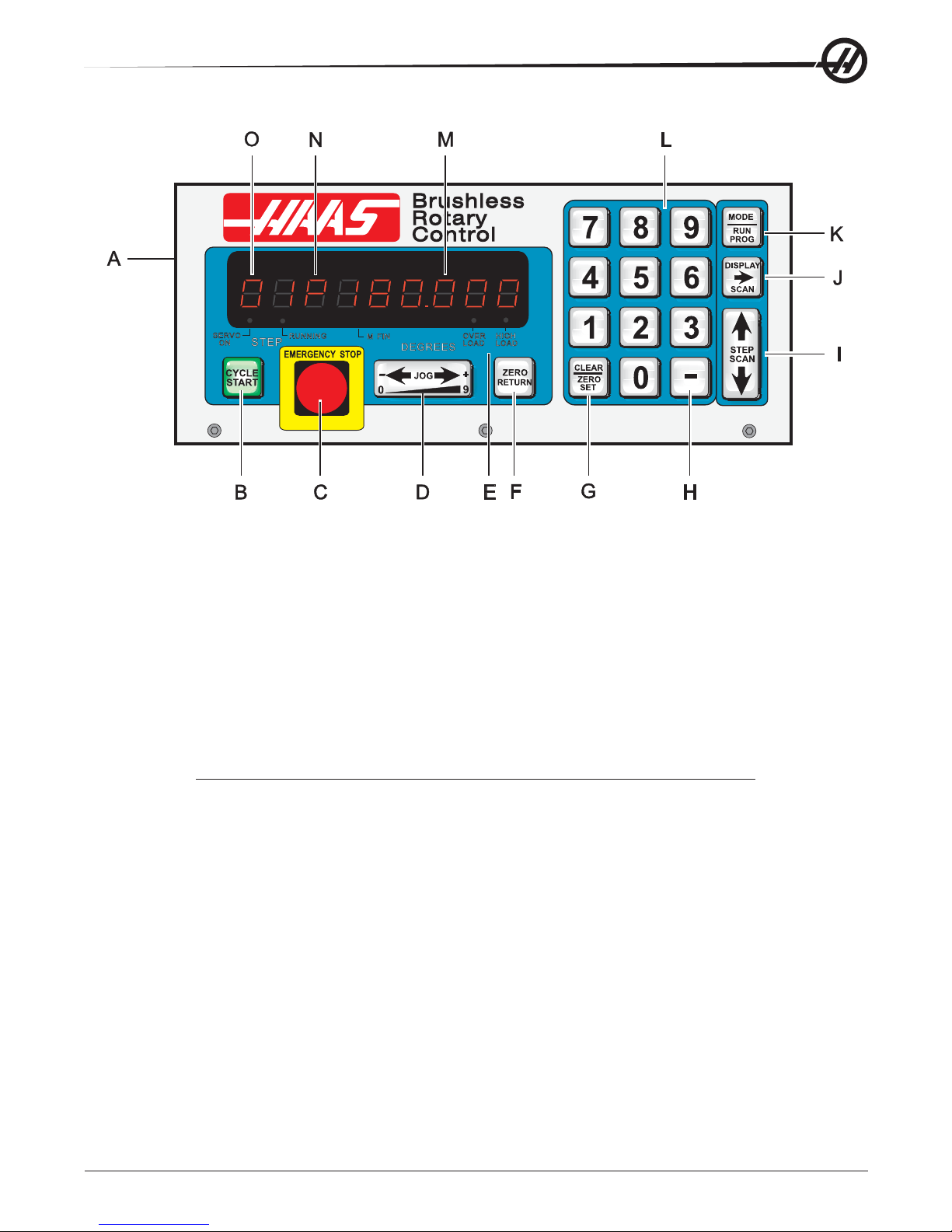
A) Main POWER switch to turn the unit on (back panel).
B) CYCLE START begins a step, stops a continued operation, inserts a step, or turns the servo on.
C ) EMERGENCY STOP turns off the servo when on and aborts the step in progress.
D ) JOG causes the servo to move in either the forward or backward direction at a rate defined by the last
numeric key pressed.
E) Load meter LED. If LEDs are illuminated continuously during a low feed rate or when stationary, the
following conditions apply:
HIGH LOAD: Indicates overload level, excessive load or workpiece support misalignment. Hi-LoAd or Hi
Curr alarms may occur if not corrected. (See "Troubleshooting" section)
OVERLOAD: Indicates 2x overload level, excessive load or workpiece misalignment. Hi LoAd or Hi Curr
alarms will occur if not corrected. Damage to motor or table may result. (See "Troubleshooting" section)
NOTE: It is normal for the LEDs to be illuminated during a rapid movement or high duty
cycle.
F) ZERO RETURN causes the servo to return to HOME position, search for mechanical HOME, delete a step,
or move forward to the mechanical offset.
G ) ZERO SET clears the entered data, resets program to 0, or defines the present servo position as HOME.
H ) MINUS KEY selects negative step values or Prog/Upload/Download functions.
I ) STEP SCAN scans step numbers from 1 through 99.
J ) DISPLA Y SCAN scans the display to show either Position, S tep Angle, Feed Rate, Loop Counts, or G
Code.
K) MODE / RUN PROG switches from RUN mode to PROGRAM mode (blinking display).
L) Data entry keys and jog speed selection.
M) Displays show current data, i.e., a current spindle position of 180.
N ) Indicates what data is being displayed. Either P, F, L, blank, or G for Position, Feed Rates, Loop Count,
Step Angle, or G Code.
O ) Present step number. Step numbers 1 to 99 are available. Also displays errors at turn on.
96-5047 rev L June 2005
25

3.2 TURNING T HE S ERVO O N
There is a single 115V AC @ 15 amp supply required by the controller . Ensure that the front p anel power switch
is turned off (Brushless units have the power switch on the rear) and connect the motor cable from the table
and the power cord.
Turn the controller on. The display will show:
HAAS nn
where nn is the sof tware revision number . That number should be used when describing problems to HAAS. If
any other message is displayed, refer to the "Error Codes" section of this manual. The number only remains in
the display for about one second. The front panel displays should indicate:
Por On
This indicates that the servo is turned off (no power is applied to the closed-loop motor).
In addition, the internal battery is checked at power-on and if the battery is low the following message is
displayed:
Lo bAt
Pressing any key will allow you to continue operation, but the low battery may have caused loss of your
program parameters.
Press the front panel ST ART switch once. The panel should now indicate:
01 no Ho
This indicates that the motor is powered, but the zero position is not yet defined.
3.3 AUTOMATICALLY F INDING T HE Z ERO POSITION
Press the ZERO RETURN button to start the automatic homing operation. When the table stops, the display
will indicate:
01 Pnnn.nnn
3.4 MANUALLY F INDING THE Z ERO P OSITION
Use the left/right JOG switch to position the table to the position that you want to use as zero and then press
and hold the CLR key for three seconds. The display should now indicate:
01 P 000.000
This indicates that the zero position is established and the controller is ready to begin normal operations. If a
different position is to be used as zero, jog the table to the new position and press the CLR key for three
seconds. The display will again indicate:
01 P 000.000
If you had previously cleared a new HOME position for the table, the display will show a non-zero position. In
this case, press the ZERO RETURN button once more and the table will move forward to the pre-defined zero
position.
26
96-5047 rev L June 2005

3.5 JOGGING
Jogging of the motor can be done with the front panel JOG switch. The jog speed is selected with the front
panel number keys and is a fraction of the maximum feed rate set by the parameters. The jog speeds (for the
HRT 160) are:
Number pressed Speed (% of maximum) Jog speed (for 80 deg/sec max.)
0 0.008 0.006 Deg/sec
1 0.015 0.012 Deg/sec
2 0.031 0.024 Deg/sec
3 0.062 0.049 Deg/sec
4 0.125 0.100 Deg/sec
5 0.25 (default) 0.200 Deg/sec
6 0. 5 0.400 Deg/sec
7 1. 0 0.800 Deg/sec
8 4. 0 3.200 Deg/sec
9 16.0 12.800 Deg/sec
If the control is set up for linear motion, positive and negative travel limits are possible. If a step is started which
would have caused the control to exceed travel limits, the following message is shown:
2 FAr
and the control will not execute the step. (See parameter 13 and 14, travel range)
3.6 ERROR C ODES
When the controller is first turned on, a set of self tests is run and the results may indicate a controller fault.
Any of these could result in an En display of one of the following codes:
Blank front panel Program CRC failure (bad RAM, or cycle power if bad ROM to RAM program transfer.)
E0 EProm EPROM CRC error
FP Short Front panel switch closed (or PIO fault)
rE Short Remote ST ART switch closed and enabled
E3 rAm RAM cannot store data
E4 bAtt Saved program is in error (low battery)
E5 Pio2 PIO2 is bad
E6 Pio3 PIO3 is bad
Lo V olt Power-fail interrupt (low line voltage)
E8 Encod Encoder chip bad
E9 intEr Interrupt problem
EA no go Keep alive circuit failure
Eb nmi NMI sense bad
Ec Pwm PWM generation bad
Ed cloc 1 kHz signal missing
EE Au in Auxiliary input 2 shorted
Lo bAt Low battery (Get serviced)
rLS Err Exceeding maximum allowed rotary scales compensation. HRT210SC only
Intermittent low voltage errors or power failures may be the result of inadequate power to the controller . Use
heavy duty extension cords only and keep them as short as possible. Make sure power service is a minimum
of 15 amps at the plug and that the voltage is a minimum of 115 V AC.
96-5047 rev L June 2005
27

0 too SL (Zero margin too small) Zero margin too small is the distance between the home switch
and the final stopped motor position, after seeking home, is either less than 1/8 or greater
than 7/8 of a motor revolution.
This alarm may occur while homing the rotary table. The distance between the home switch and the final motor
position at zero is less than 1/8 of a motor revolution. To prevent this alarm, parameter 45 must be set properly.
Start with the default value for p arameter 45 (0) and add 1/2 of a motor revolution (1/2 motor revolution is equal
to the value in parameter 28 divided by 2). Home the rotary table after the new value for parameter 45 has been
entered.
There are no user-serviceable parts inside, so refer all problems to HAAS Automation for
repair.
3.7 SERVO O FF C ODES
At any time the servo is turned off, a reason code is displayed along with the following codes:
Por On Power was just turned on (or failed prev.)
Ser Err Servo following error too large
E-StoP Emergency stop
Hi LoAd Software fuse
rS-232 Remote RS-232 commanded off
Air-Hot Motor overheat sensor
EncodEr Z channel fault (bad encoder or cable)
REncodEr Rotary scale Z channel fault (bad rotary scale encoder or cable) HRT210SC only
Hi Curr Over current limit (stalled or PCB fault)
EncodES Z channel missing (bad encoder or cable)
rEncodES Rotary scale Z channel missing (bad rotary scale encoder or cable) HRT210SC only
Hi V oLt Regen overheat (high line voltage)
CABLE Break detected in encoder cable wiring
rCABLE Break detected in rotary scale cable wiring (HRT210SC only)
PHAS Er Power up phase error (Brushless units only)
dr FLt An overcurrent or drive fault.( Brushless units only)
trAnS Encoder transition fault had been detected by the brushless circuitry.
Indr dn Platter not fully up (HRT320FB only). Can be caused by low air pressure.
3.8 EMERGENCY S TOP
Pushing the EMERGENCY STOP button will turn the servo off and cause the spindle to decelerate and stop.
Position will not be lost. If the step was not completed you will still be on that step. Push CYCLE ST AR T to
turn the servo on. The remote cycle start and cycle finish will not function until the EMERGENCY STOP is
removed by pushing the ST ART button. If an EMERGENCY STOP is performed, the display will indicate an:
E-StoP
CE machines have an Emergency-stop switch on the top of the control. Pressing the E-stop switch will turn off
the servo and aborts the step in progress.
28
96-5047 rev L June 2005

4. PROGRAMMING THE CONTROLLER
4.1 INTRODUCTION
Programming is done through the square 15-key keypad on the right side of the front panel. The three buttons
on the right column of the keypad are used for program control. They are the:
MODE / RUN PROG button,
DISPLA Y SCAN (RIGHT ARROW) button
STEP SCAN (UP/DOWN ARROWS) button
The MODE button is the most important. It selects between the RUN mode and PROGRAM mode. You can tell
which mode you are in by looking at the display .
IF THE DISPLA Y IS STEADY, YOU ARE IN THE RUN MODE.
IF IT IS FLASHING ON AND OFF, YOU ARE IN THE PROGRAM MODE.
The RUN mode is where pre-programmed commands may be executed and the PROGRAM mode where
commands are entered into memory . The servo loop can be turned on in either mode and will hold the motor to
a commanded position when at standstill.
When the controller is first turned on, it is in RUN mode but the servo is turned off. This is indicated by:
Por On
Pressing any key will allow you to continue operation.
Some buttons have more than one function depending upon which mode you are in. Always release a button
immediately after pressing it. Holding a button down will cause it to repeat.
Feedrate will default to maximum (rapid) for HRT320FB.
4.2 HOW D ATA IS S TORED IN THE C ONTROLLER'S M EMORY
Step Number Step Size Feed Rate Loop Count G code
1 90.000 80 01 91
2 -30.000 05 01 91
3 0 80 01 99
through
9 9 0 80 01 99
- your program data -
window Pushing the right arrow key moves the window to the right.
Pushing the up arrow or down arrow keys moves the window up or down.
96-5047 rev L June 2005
29

4.3 ENTERING A STEP
To enter a step into the controller's memory, press the MODE button. This will put the controller into the
PROGRAM mode. The display will begin blinking and show a step size. Clear the last program by pressing and
holding the CLR key for three seconds. To enter a 45 degree (45o) step, press the following keys:
4 5 0 0 0
The display should now indicate:
01 45.000
Press the right arrow button. This will cause the 45 degree (45o) step to be stored and the feed rate to be
displayed. To enter a feed rate of 80 degrees (80o) per second, press the following keys:
8 0 0 0 0
The display should now indicate:
01 F 80.000
T o return the controller to the RUN mode, press the MODE button. The display should now indicate:
01 P 000.000
St art the 45 degree (45o) step by pressing the CYCLE ST ART button. The table should move to the new
position and at the end of the step, the display should indicate:
01 P045.000
4.4 PUTTING A PROGRAM I NTO MEMORY
Programming begins with ensuring that the controller is in PROGRAM mode and at step number 01. To do this,
press the MODE button while the servo is NOT in motion. The displays must be blinking. Next, push and
HOLD the clear (CLR) key for five seconds. Y ou have now cleared the memory and are at step one and ready
to begin programming. “01 000.000 “ should be displayed. Please note that you do not have to clear the
memory each time you wish to enter or change data. Data in the program can be changed simply by writing
the new data over the old.
Up to 7 programs can be stored, numbered 0 to 6. To access a different program, press the minus key while
showing a G code. The display will change to:
Prog n
Press a number key to select a new program and then press the MODE key to return to RUN mode or the
ST ART key to continue with the PROGRAM mode.
Every one of the possible 99 steps in a program may contain the following:
1. a step size or position command (shown as a number with possible minus sign),
2. a feed rate shown with a preceding F,
3. a loop count shown with a preceding L,
4. a G code shown with a preceding G, and
5. a jump destination with a preceding Loc.
Every step must contain at least one G code. The following section describes the possible G codes.
30
96-5047 rev L June 2005

To display the additional codes associated with a step, press the right arrow key. Possible data entry includes:
Step size (no code letter but possible minus sign),
Feed rate (F),
Loop count (L),
G code (G), and
Subroutine jump destination step number (Loc).
Some of these entries are not allowed for particular G codes and either cannot be entered or are ignored. Most
steps are incremental position commands and this is the default G code (91). The G codes 86, 87, 89, 92, and
93 should be used with the CNC relay function disabled (Parameter 1 = 2).
Enter your step size in degrees to three decimal places. The decimal places must always be entered, even if
they are zero. Enter a (-) minus sign for opposite rotation. If you need to edit a feed rate or loop count, push the
right arrow key to view that register and input the data.
If you are programming for a part that does not utilize feed rates or loop counts, simply push the down arrow to
go to the next step. Insert the G code and step size and move on to the next step. The step will automatically
be set to the fastest feed rate and a loop count of one.
The data you input is automatically stored in memory whenever you push one of the control buttons.
If you enter a wrong number or one that is out of limits the control will display an error message:
Error
T o correct this, push the CLR button and re-enter the correct number . If you are entering the correct number
and Error still appears, check Parameter 7 for memory protect.
When the last step has been entered, an end code must be present at the following step. Step s 2 through 99
are set to the end code when a clear memory is performed. This means that you usually do not need to set the
last step to 99. If you are removing steps from an existing program, make sure that you have entered a (99)
after the last step.
Note: The HRT320FB will not allow a feedrate to be entered. It only indexes at maximum speed.
4.5 G CODES
The following G codes are possible:
G28 return to HOME position (same as G90 with step 0)
G73 peck cycle (linear operation only)
G85 fractional circle division
G86 turn CNC relay on
G87 turn CNC relay off
G88 return to HOME position (same as G90 with step 0)
G89 wait for remote input
G90 absolute position command
G91 incremental command
G92 pulse CNC relay and wait for remote input
G93 pulse CNC relay
G94 pulse CNC relay and run next L steps automatically
G95 end of program/return but more steps follow
G96 subroutine call/jump (destination is a step number)
G97 delay by L count/10 seconds (down to 0.1 second)
G98 circle division (circular operation only)
G99 end of program/return and end of steps
96-5047 rev L June 2005
31

4.6 ABSOLUTE / INCREMENTAL M OTION
G90 and G91 are used to select absolute (G90) or incremental (G91) motion. G90 is the only command
allowing absolute positioning.
4.7 FEED R ATES
The feed rate display ranges between 00.001 and 080.000 (Maximum 080.000 for HRT 160, 060.000 for HRT
210, 050.000 for HRT 310, and 050.000 for HRT 450), preceded by an F. It displays the feed rate that will be
used for the selected step. The feed rate corresponds to degrees rotated per second. A feed rate of 080.000
means the platter will rotate 80 degrees (80o) in one second.
4.8 LOOP C OUNTS
Loop Counts allow you to repeat a step up to 999 times before going on to the next step. The loop count
display is three digits between 1 and 999 preceded by an L. In RUN mode, it displays the remaining loop
counts for the selected step. It is also used in conjunction with the Circle Division function to enter the
number of divisions in the circle from 2 to 999. Used in conjunction with G96, the Loop Count specifies the
number of times you wish to repeat that subroutine.
4.9 SUBROUTINES (G96)
Subroutines allow you to repeat a particular step sequence up to 999 times. A subroutine is invoked by entering
96 into the G code. Af ter entering 96 you must DISPLA Y SCAN over to the LOC (short for location) register to
enter the step you wish to jump to. The location register replaces the feed rate register and is only present on
G96 steps. Af ter executing a G96 step, the control will jump to the step called out in the LOC register , execute
that step and the ones following until it reaches G code 95 or 99, the end of subroutine call. The program then
jumps back to the step following G96.
A subroutine can be repeated a number of times by utilizing the loop count of the G96 step. To end the subroutine, you must insert a G code of 95 or 99 after the last sequence step. A subroutine call is not considered a
step by itself since it will always execute itself and the first step of the subroutine. Nesting of subroutine calls
is not permitted.
4.10 DELAY C ODE (G97)
G97 is used to program a dwell or delay time into a program. G97 does not pulse the CNC relay at step
completion. As an example, programming a G97 and setting L=10 will produce a 1 second dwell.
4.11 CIRCLE DIVISION (G98)
Circle division is selected with a G98. The L count defines how many equal sized parts a circle is to be divided
into. After the L count steps, the servo will be in the same position as it started. Circle division is only available
in the circular modes (i.e., Parameter 12=0, 5, or 6).
32
96-5047 rev L June 2005

4.12 AUTO C ONTINUE C ONTROL
If Parameter 10 is set to 2, the controller can be run like a single axis CNC. The entire program will be executed until the last step is encountered. In all cases, the last step is the one with a G99. Actually, the step
preceding the G99 is the last one to be executed. Step 99 may also be the last step if all of memory is used.
When running automatically , the sequence of step operation can be stopped by pressing and holding the
ST ART switch until the current step is finished. The program can then be continued by pressing ST AR T again.
4.13
II
INSERTING A L INE
II
A new step may be inserted into a program by pressing and holding the CYLE START button for three seconds
while in PROGRAM mode. It will cause the present step and all following steps' contents to be moved down
and the present step to be initialized to default values. All subroutine jump s are also renumbered.
4.14 DELETING A L INE
A step may be deleted from a program by pressing and holding the ZERO RETURN button for three seconds
while in PROGRAM mode. It will cause the next step and all following steps to be moved up by one. All
subroutine jumps are also renumbered.
4.15 DEFAULT V ALUES
For all steps, the default values are:
000.000 (step size zero)
F (maximum feed rate defined by Parameters)
L 001
G 91 (incremental)
If an entry is cleared or set to 0 by the operator, the controller will be set to the default value. All entries are
stored when selecting the next display function, step number, or returning to RUN mode.
4.16 SELECTING A S TORED P ROGRAM
There can be more than one stored program, and selection of that program is done by pressing the minus (-)
key while showing a G code in PROGRAM mode. The display will change to:
Prog n
Press a number key to select a new program and then press the MODE key to return to RUN mode or the
ST ART key to continue with the PROGRAM mode. There are seven programs available, numbered 0-6.
4.17 CLEARING A P ROGRAM
T o initialize or clear a stored program (not including Parameters), go to PROGRAM mode (press the MODE
button if displays are not blinking) and press and hold the CLR button for three seconds. The displays will cycle
through all 99 steps and set all but the first to G99. The first step is set to G91, step size of 0, maximum feed
rate, and a loop count of 1.
96-5047 rev L June 2005
33

4.18 OPERATING H INTS
1. You can select another display while in the RUN mode by pushing the DISPLA Y SCAN button.
This way you could view the particular feed rate for a step or view the remaining loop counts left.
2. You can start your program on any step by using the UP/DOWN scan keys.
3. Make sure your CNC has the same number of M functions programmed as you have steps in the
HAAS control.
4. DO NOT program two M functions one directly after another in your CNC control to index the
HAAS control, as this may cause a timing hang-up in your CNC. Use a dwell of 1/4 second
between them.
5. If all else fails, read the manual again.
4.19 SIMULTANEOUS R OTATION AND M ILLING
G94 can be used to perform simultaneous milling. The CNC relay is pulsed at the beginning of the step so that
your NC machine will proceed to the next block. The controller then executes the following L steps automatically without waiting for start commands. Normally the L count on the G94 is set to 1 and that step is followed
by a step that is to be run simultaneously with an NC mill.
4.20 SPIRAL M ILLING
The simultaneous rotation and milling feature of the controller will permit machining of certain cam forms, spiral,
and angular cuts. S piral milling is when the spindle rotates and an axis on your mill moves at the same time.
Insert a G94 into the control and the desired rotation and feed rate on the next step. The control will execute
G94 (this pulses the MFIN relay and allows your CNC to proceed) and the following step or steps as one step.
If you wish to do more than one step, then insert the number into the L register. By selecting a rot ation feed
rate and varying the mill feed rate, any spiral is possible. In order to spiral mill, you will have to calculate the
feed rate for your mill so that the HAAS spindle and your axis will stop at the same instant.
In order to calculate the feed rate for your mill you need to know:
1. The angular rotation of the spindle (this should come from the print)
2. A feed rate for the spindle (arbitrarily select a reasonable one, five degrees (5o) per second is a
good starting point)
3. The distance you wish to travel on X-axis (this should come from the print)
For example, we wish to mill a spiral that is 72 degrees (72o) of rotation and moves 1.500 inches on the X-axis
at the same time.
1. Compute the amount of time it will take the HAAS index head to rotate through the angle
# of degrees /(divided by) feed rate of spindle = time to index
72 degrees/ five degrees per sec = 14.40 seconds for indexing head to rotate.
2. Now we need to compute the feed rate for the mill that will travel the X distance in 14.40 seconds.
(length to travel in inches/(divided by) # of seconds of rotation) x 60 seconds = feed rate for mill in
inches per minute.
1.500 inches/14.4 seconds = 0.1042 inches per second x 60 = 6.25 inches per minute.
34
96-5047 rev L June 2005

Therefore, if you set the indexer to step 72 degrees (72o) at a feed rate of five degrees (5o) per second you
will have to program your mill to travel 1.500 inches at a feed rate of 6.25 inches per minute for the spiral to be
generated.
The program for the HAAS control would be as follows:
STEP STEP SIZE FEED RATE LOOP COUNT G CODE
01 0 080.000 1 [94]
02 [72000] [5.000] 1 [91]
03 0 080.000 1 [88]
04 0 080.000 1 [99]
The program for your mill would generally look like this:
N1 G00 G91 (rapid in incremental mode)
N2 G01 F10. Z-1.0 (feed down in Z-axis)
N3 M21 (to start indexing program above at step one)
N4 X-1.5 F6.25 (index head and mill move at same time here)
N5 G00 Z1.0 (rapid back in Z-axis)
N6 M21 (return indexer HOME at step three)
N7 M30
4.21 POSSIBLE T IMING P ROBLEMS
When the HRT executes a G94, a 250 millisecond delay is required before executing the following step. This
may (it usually doesn’t) cause your axis to move before the table rotates, leaving a flat spot in the cut. If this is
a problem, a solution is to insert a G04 dwell (from 0 to 250 milliseconds) in your CNC after the M function to
prevent axis movement. By selecting the right dwell, the HRT and your mill should start moving at the same
instant. In the same manner , a problem may exist at the end of the spiral, but this can be eliminated by slightly
altering the feed rate on your mill. Don’t adjust the feed rate on the HAAS control because your mill has a
much finer feed rate adjustment than the HAAS control. If the undercut appears to be in the X-axis direction,
then speed up slightly (0.1 change in feed rate) your mill’s feed rate. If the undercut appears in the radial
direction of the spindle of the indexer, then slow down your mill’ s feed rate.
If the timing is off by several seconds such that your mill completes movement before the indexer completes
it’s movement, and you have several spiral moves one right after another (such as in retracing a spiral cut), this
may cause your CNC to stop for no reason. The reason for this is your CNC will send a cycle start signal (for
next cut) to the HAAS control before it has completed its first move, thereby causing a timing hang-up. The
HAAS control will not accept another cycle start until it is finished with the first. If you are doing multiple moves
it is very important to check your timing calculations. A way to verify if this is actually the problem is to single
block your control, allowing five seconds between steps. If you can single block the control but it will not
successfully run in the continuous mode, then your timing is off somewhere.
96-5047 rev L June 2005
35

Example #1
5. PROGRAMMING EXAMPLES
We want to index the platter 90 degrees (90o).
1. Turn [POWER] switch on. (The power switch is located on the rear panel.)
2. Push the [CYCLE ST ART] switch.
3. Push the [ZERO RETURN] switch.
4. Push the [MODE] button and release. Displays must be blinking.
5. Push and hold [CLR] button for five seconds. “01 000.000” displayed.
6. Enter [9 0 0 0 0]
7. Push [MODE] button. Steady displays.
8. Push [CYCLE ST ART] to index.
36
96-5047 rev L June 2005

Example #2
Continuing the previous example, we want to index the platter 90 degrees (Step 1), rotate at five degrees/sec
(F5) in the opposite direction for 10.25 degrees (Step 2), and then return home (S tep 3).
9. Push the [MODE] button. Displays blinking.
10. Push the [DOWN ARROW] once. You should be on Step 2.
11. Enter [- 1 0 2 5 0] on the key pad. Use CLR if you make a mistake.
12. Push the [DISPLAY SCAN] button once.
13. Enter [5 0 0 0] on the keypad.
14. Push the [DISPLAY SCAN] button twice. A “G 91” will be displayed.
15. Push the [DOWN ARROW] once. You should be on Step 3.
16. Enter [8 8] on the keypad.
17. Push the [UP ARROW] twice. You should be on Step 1.
18. Push the [MODE] button. S teady displays.
19. Push the [CYCLE ST ART] switch three times. The table should index 90 degrees (90o),
slow feed in the opposite direction for 10.25 degrees (10.25o), and return home.
96-5047 rev L June 2005
37

The following examples show the program as you would enter it into the control. We will assume each time
that you have cleared out the memory . The bold-face type surrounded by [ ] indicates data that you would enter
into the controller.
Example #3
We want to drill a four-hole pattern, and then a five-hole pattern on the same part.
STEP STEP SIZE FEED RATE LOOP COUNT G CODE
01 [90.000] 080.000 [4] [91]
02 [72.000] 080.000 [5] [91]
03 0 080.000 1 [99]
Example #3 could have also been done using Circle Division.
STEP FEED RATE LOOP COUNT G CODE
01 080.000 [4] [98]
02 080.000 [5] [98]
03 080.000 1 [99]
Example #4
We want to index 90.12 degrees (90.12o), start a seven-hole bolt pattern, and then return to the zero position.
STEP STEP SIZE FEED RATE LOOP COUNT G CODE
01 [90.120] 080.000 1 [91]
02 0 080.000 [7] [98]
03 0 080.000 1 [88]
04 0 080.000 1 [99]
Example #5
We want to index 90 degrees (90o), then slow feed for 15 degrees (15o), repeat this pattern three times, and
return home.
STEP STEP SIZE FEED RA TE LOOP COUNT G CODE
01 [90.00] 080.000 1 [91]
02 [15.00] [25.000] 1 [91]
03 [90.00] 080.000 1 [91]
04 [15.00] [25.000] 1 [91]
05 [90.00] 080.000 1 [91]
06 [15.00] [25.000] 1 [91]
07 0 080.000 1 [88]
08 0 080.000 1 [99]
38
96-5047 rev L June 2005

This is the same program (Example #5) using subroutines.
STEP STEP SIZE FEED RA TE LOOP COUNT G CODE
01 0 LOC [4] [3] [96]
02 0 080.000 1 [88]
03 0 080.000 1 [95]
04 [90.00] 080.000 1 [91]
05 [15.00] [25.000] 1 [91]
06 0 080.000 1 [99]
Explanation:
Step #1 tells the control to jump to Step #4. The control will do steps #4 and #5 three times, with S tep #6
marking the end of the subroutine. Af ter finishing the subroutine, the control jumps back to the step following
the “G 96” call (in this case, Step #2). Since Step #3 is not part of a subroutine, it marks the end of the program and will return the control to Step #1.
Using subroutines in Example #5 saves only two lines of programs. However, if you wanted to repeat the
pattern eight times, you would save twelve program lines. In the subroutine example, only the loop count in
Step #1 would be changed to increase the number of times you wish to repeat the pattern.
As an aid in programming subroutines, think of the subroutine as a separate program and write it on a piece of
paper . Program the control using “G96” when you want to invoke the previously written subroutine. When
finished, end the program with an End 95 code. Now enter your subroutine and note the step it begins with.
Enter that step in the LOC register of the “G96” call.
Example #6
We want to index 15, 20, 25, 30 degrees in sequence four times and then drill a five-hole bolt pattern.
STEP STEP SIZE FEED RATE LOOP COUNT G CODE
01 0 Loc [4] [4] [96]
02 0 080.000 [5] [98]
03 0 080.000 1 [95]
(main program above———subroutine below)
04 [15.000] 080.000 1 [91]
05 [20.000] 080.000 1 [91]
06 [25.000] 080.000 1 [91]
07 [30.000] 080.000 1 [91]
08 0 080.000 1 [99]
96-5047 rev L June 2005
39

6. PROGRAMMABLE PARAMETERS
There are 37 stored parameters (46 for brushless units) associated with each servo controller . There is a
battery in the controller which will keep the parameters (and the stored program) saved for up to eight years.
These parameters are used to change the way the controller and servo loop operate. To change a parameter,
go to the PROGRAM mode by pressing the MODE button. Then press the up arrow and hold it at Step 1 for
three seconds. After three seconds, the display will change to the p arameter entry mode. The display will
indicate:
01 PP.nnnnn
For brushless units the display will indicate:
01U.nnnnnn
Where n is the value of Parameter 1. Parameters are one to five digits in length and are decimal integers. If
changing parameters associated with the servo loop, it is safest to do this with the servo loop off. Turn the
servo loop off by pressing EMERGENCY ST OP. T o exit from parameter entry mode, either press the MODE
button to go to RUN mode or push the down arrow key until you return to S tep 1.
The up arrow key is used to select the next higher numbered parameter and the down arrow key is used to
select the next lower numbered parameter . Pressing the up arrow, down arrow, or MODE keys will cause an
entered parameter to be stored.
Most parameters have particular values to which they must be assigned to gain an intended result. There are
several parameters, however, which give numbers to add, such as +1. With these p arameters, start at zero and
add the value for each option you would like.
Some of the parameters are protected from being changed by the user. This is because they could result in
unstable or unsafe servo operation. If you need to change any of these parameters, call HAAS Automation.
6.1 SC 4.0, 5.0 AND 9.0 PARAMETER S ETUP
The SC 4.0, 5.0 and 9.0 may require the following parameters to be recalculated for your application to enable
coordinated display feedback during operation. The default parameter list should be used as a starting point for
initial parameter settings.
1. Parameter 9 (and 20 if required) – is the calibration ratio between encoder pulses (encoder lines X4) and
your unit of measurement (degrees or inches) in steps per unit. Several examples follow:
Linear Example (6mm pitch ballscrew):
32768 (brushless) encoder pulses per revolution X 25.4 milimeters per inch / 6mm per revolution = 138718
Rotary Examples:
8000 (brush) encoder pulses per revolution X 90:1 gear ratio X 2:1 belt ratio / 360 degrees per revolution =
4000
32768 (brushless) encoder pulses per revolution X 90:1 gear ratio X 3:1 belt ratio / 360 degrees per
revolution = 24576
Rotary Example with a gear ratio divider (parameter 20) needed:
32768 (brushless) encoder pulses per revolution X 72:1 gear ratio X 2:1 belt ratio / 360 degrees per
revolution = 13107.2 since 13107.2 is non-integer we require a ratio divider (parameter 20) set to 5 then:
13107.2 ratio = 65536 (parameter 9) encoder steps / 5 (parameter 20) ratio divider .
40
96-5047 rev L June 2005

2. Parameter 12, 13, 14 – give optimum display precision (decimal location). See parameter 12 description
for your setting. If travel limits are required, linear settings of 1,2,3 or 4 must be entered in parameter 12
and parameter 13&14 must be calculated and set as follows: (Entered value loses last digit.)
Linear Example (6mm pitch ballscrew):
20.0 inch travel X 138718 ratio = 2774360 (entered value: 277436)
Rotary Example (must also use “linear” settings of 1,2,3 or 4 entered in parameter 12):
120.0 degrees of travel X 4000 ratio = 480000 (entered value: 48000)
3. Parameter 3, 4, 17 – These parameters may have to be changed due to different motor load conditions.
Use standard values as a baseline and revise parameters based on the following:
A. Proportional gain – increases current in proportion to the proximity to the target position.
The farther from the target, the greater the current up to the maximum value in parameter
40. A mechanical analogy is a spring that will oscillate past the target unless dampened
by the derivative gain.
B. Derivative gain – resists motion effectively braking oscillations. This parameter is increased
in proportion to the p gain.
C. Integral gain – provides larger increases of current to achieve target. This parameter , set
too high, will often cause a hum.
4. Parameter 27 – options for home switch usage (required for repeatability after control shutdown).
All HAAS Indexers use a home switch used in conjunction with the Z pulse on the motor encoder (one for
each revolution of the motor) for repeatability . The home switch consists of a magnet (Haas PN 69-18101)
and proximity switch (Haas PN 36-3002), which is of the magnetically sensitive transistor type. When the
control is shut down and restarted, it will give a “no home” display , requiring the user to press the “zero
return” button. The motor then operates slowly in a clockwise direction (as viewed from the platter of a
rotary table) until the proximity switch is magnetically tripped and then backs up to the first Z pulse. (See
parameter code options in parameter section for actual options.) Note: to reverse direction when seeking a
home switch (if it currently moves away from the home switch during the home sequence), add 256 to the
value in parameter 27. Note: A home switch is not required for parameter 27. Setting Parameter 27 to 2 will
home at first Z pulse. To repeat home position when set to 2, the system must be jogged by using the
arrow keys to be manually moved within one revolution of the motor before homing the unit.
5. Summary of additionally useful parameters to SC 4.0, 5.0 and 9.0 users:
A. Parameter 7 – protect a program that won’t be changed often.
B. Parameter 10 – continuous cycle repetition.
C. Parameter 11 – reverse the sign (+ or –) on the control display to match your positive direction
convention.
D. Parameter 15 – to enable precise positioning for reversed motion (compensating for mechanical
backlash).
E. Parameter 16 – dwell time between programmed steps. Also functions to cool motor for long motor
life.
F . Parameter 18 – lower number allows for gentler acceleration ( this value must be greater than
parameter 19, usually 2X).
G . Parameter 19 – lower number reduces speed (RPM of motor).
Formula: degrees (or inches) per sec X ratio (parameter 9) / 100 = entered value in parameter 19.
H. Parameters 25,32 – if your system has a brake, it must be timed to avoid motor overheat.
Motor Parameters 23, 28, 29, 36-45 should not be changed! This can damage the motor and will
void the warranty!
96-5047 rev L June 2005
41

6.2 GEAR C OMPENSATION
The control has the ability to store a compensation table to correct for small errors in the worm gear. The gear
compensation tables are part of the parameters. While parameters are displayed, press the right arrow button
to select the gear compensation tables. There is a separate plus direction table from the minus direction table.
Use the right arrow button to display the plus or minus table. The gear compensation data is displayed as:
gP Pnnn cc for plus table
G- Pnnn cc for minus table
The nnn value is the machine position in degrees and the cc is the compensation value in encoder steps.
There is a table entry every two degrees starting at 001 and going to 359. If your control has non-zero values in
the gear compensation tables, it is recommended that you do not change them.
When the gear compensation tables are displayed, the up and down arrow button will select the next two
degree (2o) entry and the minus (-) and numeric buttons will enter a new value. In addition to this, the JOG
button may be used to adjust the compensation value. If the servo is on when changes are made, and the table
is at the position corresponding to the entry changed, the servo motor will move by the adjustment amount.
This is valuable in that the JOG button can be used to move the motor to a desired position.
Clearing of parameters will set all of the gear compensation tables to zero. To exit the gear compensation
display, press the MODE button; this returns the control to RUN mode.
When a table is using gear compensation, the values in Parameter 1 1 must be set to "0".
6.3 PARAMETER L IST
The following is a list of the programmable parameters:
If the brushless software ranges are different, they will be shown in parentheses.
Parameter 1: CNC Interface Relay Control, range 0 to 2
0: relay active during indexer motion
1: relay pulsed for ¼ second at end of motion
2: no relay action
Parameter 2: CNC Interface Relay Polarity & Aux. Relay Enable, range 0 to 3
0: normally open
+1: normally closed
+2: optional relay number 2 pulsed at end of program
Parameter 3: Servo Loop Proportional Gain, range 0 to 255 PROTECTED!
Servo loop proportional gain increases current in proportion to the proximity to the target position. The
farther from the target, the greater the current up to the maximum value in parameter 40. A mechanical
analogy is a spring that will oscillate past the target unless dampened by the Derivative gain.
Parameter 4: Servo Loop Derivative Gain, range 0 to 255 (0 to 99999) PROTECTED!
Servo loop derivative gain resists motion effectively braking oscillations. This parameter is increased in
proportion to the p gain.
Parameter 5: Double Remote Trigger Option, range 0 to 1
When this parameter is set to 1, the remote ST AR T must be triggered twice to activate the control. When
it is zero, each activation of the remote input will trigger a step.
42
96-5047 rev L June 2005

Parameter 6: Disable Front Panel Start, range 0 to 1
When this parameter is set to 1, the front panel ST AR T and HOME buttons will not work.
Parameter 7: Memory Protection, range 0 to 1
When this parameter is set to 1, no changes can be made to the stored program. This does not prevent
the changing of parameters.
Parameter 8: Disable Remote Start, range 0 to 1
1: The remote start input will not work
Parameter 9: Encoder Steps per Programmed Unit, range 0 to 65535 (0 to 99999)
This parameter defines the number of encoder steps required to complete one full unit (degree, inch,
millimeter, etc).
Example 1: A Brush HRT with a 2000 line encoder (with four pulses per line, or quadrature), a 72:1 gear
ratio, and a final drive of 2:1 would produce:
[8000 x (72 x 2)] / 360 = 3200 steps for 1 degree of motion.
Example 2: A Brushless HR T with 8192 line encoder (with quadrature), a 90:1 gear ratio and a final drive of
3:1 would produce:
[32768 x (90 x 3)] / 360 = 24576 steps for 1 degree of motion.
Parameter 10: Auto Continue Control, range 0 to 3
0: Stop after each step
1: Continue all looped steps and stop before next step
2: Continue all programs until end code 99 or 95
3: Repeat all steps until stopped manually
Parameter 11: Reverse Direction Option, range 0 to 3 PROTECTED!
This parameter consists of two flags used to reverse the direction and the motor drive and encoder . St art
with a zero and add the number shown for each of the following selected options:
+1 Reverse the direction of positive motor motion
+2 Reverse the polarity of motor power
Changing both flags to the opposite state will reverse the direction of motor motion.
Parameter 12: Display Units and Precision (decimal location), range 0 to 6. Must be set to 1,2,3, or 4 if travel
limits are to be used (including circular motion with travel limits).
0: degrees and minutes (circular)
Use this setting to program four digits of degrees up to 9999 and two digits of minutes.
1: inches to 1/10 (linear)
2: inches to 1/100 (linear)
3: inches to 1/1000 (linear)
4: inches to 1/10000 (linear)
5: degrees to 1/100 (circular)
Use this setting to program four digits of degrees up to 9999 and two digits of fractional degrees to
1/100.
6: degrees to 1/1000 (circular)
Use this setting to program three digits of degrees up to 999 and three digits of fractional degrees
to 1/1000.
96-5047 rev L June 2005
43

Parameter 13: Maximum Positive Travel, range 0 to 65535 (0 to 99999)
This is the positive travel limit in units*10 (entered value loses last digit). It applies only to linear motion
(i.e. Parameter 12=1,2,3, or 4). If it is set to 1000, positive travel will be limited to 100 inches. The entered
value is also affected by the gear ratio divider (parameter 20).
Linear example (6mm pitch ballscrew): 20.0 inch travel X 138718 ratio = 2774360 (entered value: 277436)
Rotary example (must also use “linear” settings of 1,2,3 or 4 entered in parameter 12): 120.0 degrees of
travel X 4000 ratio = 480000 (entered value: 48000)
Rotary Example (with a parameter 20 value of 3): 120.0 degrees of travel x 4000 ratio/3 = 160000
(entered value: 16000).
Parameter 14: Maximum Negative Travel, range 0 to 65535 ( 0 to 99999)
This is the negative travel limit in units*10 (entered value loses last digit). It applies only to linear motion
(i.e. Parameter 12=1,2,3, or 4). For examples see parameter 13.
Parameter 15: Backlash Amount, range 0 to 99
This parameter is used to compensate electronically for mechanical gear backlash. It is in units of encoder
steps. Note: this parameter cannot correct mechanical backlash.
Parameter 16: Auto Continue Dwell, range 0 to 99
This parameter causes a pause at the end of a step when the automatic continuation option is used. The
delay is in multiples of 1/10 second. Thus, a value of 13 will give 1.3 seconds of delay .
Used primarily for continuous duty, allowing for motor cool down time and longer motor life.
Parameter 17: Servo Loop Integral Gain, range 0 to 255 PROTECTED!
Servo loop integral gain. In addition to the range of 0 to 255, if the integral is to be disabled during
deceleration (for less overshoot), set Parameter 24 accordingly . Integral gain provides larger increases of
current to achieve target. This parameter , set too high, will of ten cause a hum.
Parameter 18: Acceleration, range 0 to 30000 (0 to 999999x100) PROTECTED!
This parameter defines how fast the motor is accelerated up to the desired speed. The value used in
(par 18)*100 in encoder steps/second/second. The highest acceleration is thus 3000000 steps per
second per second. It must be greater than or equal to Parameter 19, usually 2X. Lowering this value
results in gentler acceleration.
Parameter 19: Maximum Speed, range 0 to 10000 (0 to 999999x100)
This parameter defines the maximum speed (RPM of motor). The value used is (par 19)*100 in encoder
steps/second. The highest speed is therefore 1,000,000 steps per second. It must be less than or equal to
Parameter 18. If this parameter exceeds Parameter 36, only the smaller number is used. See Parameter
36 also. The entered value = the desired value/parameter 20 if a gear ratio divider is used.
Lowering this value results in reduced maximum speed (maximum motor RPM).
Standard Formula: degrees (or inches) per sec X ratio (parameter 9) / 100 = entered value in parameter
19.
Formula with Gear Ratio Divider (parameter 20): degrees (or inches) per second X ratio (parameter 9)/
[ratio divider (parameter 20) x 100] = entered value in parameter 19.
Parameter 20: Gear Ratio Divider, range 0 to 100 PROTECTED!
This parameter can be used to select non-integer gear ratios for Parameter 9. If Parameter 20 is set to
2 or more, Parameter 9 is divided by Parameter 20 before it is used. If this parameter is set to 0 or 1, no
change is made to the Parameter 9 value.
Example 1: Parameter 9=2000 and Parameter 20=3, the number of steps per unit will be 2000/3 =
666.667.
Example 2 ( with a gear ratio divider parameter 20 needed):
32768 (brushless) encoder pulses per revolution X 72:1gear ratio X 2:1 belt ratio / 360 degrees per
revolution = 13107.2 since 13107.2 is non-integer we require a ratio divider (parameter 20) set to 5 then:
13107.2 ratio = 65536 (parameter 9) encoder steps / 5 (parameter 20) ratio divider .
44
96-5047 rev L June 2005

Parameter 21: RS-232 Interface Axis Select, range 0 to 9
When this parameter is zero, no remote RS-232 functions are available. Must be set to zero when
uploading or downloading programs. When it is 1 to 9, that number is used to define the axis code for this
controller. U is 1, V is 2, W is 3, X is 4, Y is 5, and Z is 6. 7 through 9 are other ASCII character codes.
Parameter 22: Maximum Allowed Servo Loop Error , range 0 to 4000 (0 to 99999) PROTECTED!
When this parameter is zero, no maximum error limit test is applied to the servo. When it is non-zero, that
number is the maximum allowed error before the servo loop is turned off and an alarm generated. This auto
shut-off results in a display of: Ser Err
Parameter 23: Fuse Level in %, range 0 to 100 PROTECTED!
This parameter is used to define a fuse level for the servo control loop. The value is a percentage of
maximum power level available to the controller. It has an exponential time const ant of about 30 seconds.
If exactly the set level is output by the driver continuously, the servo will shut of f after 30 seconds. T wice
the set level will shut the servo off in about 15 seconds. This parameter is factory set and is usually set
from 25% to 40%, depending on the product. This auto shut-off results in a display of: Hi LoAd.
Warning! Changes from HAAS recommended values
will damage the motor.
Parameter 24: General Purpose Flags, range 0 to 1023 (0 to 4095) PROTECTED!
This parameter consists of 12 individual flags for controlling servo functions.
+1: Interpret Parameter 9 as twice entered value
+2: Disable integral while decelerating (see Parameter 17)
+4: Disable integral when brake is engaged (see Parameter 17)
+8: Protection of parameters enabled (see Parameter 30)
+16: Serial interface disabled
+32: Start-up “HAAS” message disabled
+64: Lower lag in compensation
+128: Disable Z channel encoder test
+256: Normally closed over temp sensor
+512: Disable cable test
+1024: Disable rotary scale encodercable test (HRT210SC only)
+2048: Disable rotary scale encoder Z testHRT210SC only
Parameter 25: Brake Release Time, range 0 to 19 PROTECTED!
If this parameter is zero, the brake is not activated (i.e. always engaged); otherwise this is the delay time
to release the air before the motor is started in motion. It is in units of 1/10 second. A 5 will thus delay
for 5/10 second.
Parameter 26: RS-232 Speed, range 0 to 8
This parameter is used to select data rates on the RS-232 interface. The parameter values and rates are:
0: 110 5: 4800
1: 300 6: 7200
2: 600 7: 9600
3: 1200 8: 19200
4: 2400
96-5047 rev L June 2005
45

Parameter 27: Automatic Home Control, range 0 to 255 (0 to 512) PROTECTED!
All HAAS Indexers use a home switch used in conjunction with the Z pulse on the motor encoder (one for
each revolution of the motor) for repeatability . The home switch consists of a magnet (Haas PN 69-18101)
and proximity switch (Haas PN 36-3002), which is of the magnetically sensitive transistor type. When the
control is shut down and restarted, it will give a “no home” display , requiring the user to press the “zero
return” button. The motor then operates slowly in a clockwise direction (as viewed from the platter of a
rotary table) until the proximity switch is magnetically tripped and then backs up to the first Z pulse. (See
parameter code options in parameter section for actual options.) Note: to reverse direction when seeking a
home switch (if it currently moves away from the home switch during the home sequence), add 256 to the
value in parameter 27.
This parameter is used to customize the home control function of servo.
0: no automatic home functions available (no home switch)
1: only table zero position switch available
2: only Z channel home available
3: home on both Z channel and table zero switch
+4: home if inverted Z (determined by encoder used)
+8: home to zero position in negative direction
+16: home to zero position in positive direction
+24: home to zero position in shortest direction
+32: auto servo on at power on
+64: auto search for home at power on (have “auto servo on at power up” selected)
+128: for inverted HOME switch (determined by home switch used)
+256: search for home in positive direction (Brushless Only)
Parameter 28: Encoder Steps per Motor Revolution, 0 to 10000 (0 to 99999) PROTECTED!
This parameter is used with the Z channel option to check the encoder accuracy . If Parameter 27 is 2 or
3, this parameter is used to check that the correct number of encoder steps are received per revolution.
Only two numbers are used here: 32768 for all brushless motors (8192 line encoder x quadrature)
8000 for all brush motors (2000 line encoder x quadrature)
Parameter 29: Back-EMF compensation, 0 to 999 (not used for brushless software) PROTECTED!
This parameter is used to control the adjustment of loop gain in response to motor generated back-EMF .
It is volts/Krpm times 10. Thus if the motor has 24.6 volts per KRPM this parameter is set to 246.
Parameter 30: Protection, 0 to 65535
This parameter is used to protect some of the other parameters. Every time the controller is turned on, this
parameter will have a new, random, value. If protection is selected (Parameter 24), the protected
parameters cannot be changed until this parameter is set to a different value that is a function of the initial
random value.
Parameter 31: CNC Relay Hold Time (0 to 9)
This parameter is used to specify the amount of time the CNC interface relay is held active at the end of
a step. If zero, the relay time is ¼ second. All other values give the time in multiples of 0.1 second.
Parameter 32: Delay Time for Engaging Brake, (0 to 19) PROTECTED!
This parameter is used to set to amount of time delay between the end of a motion and engaging the air
brake. It is in units of 1/10 seconds. A '4' will thus delay for 4/10 second.
Parameter 33: X-on/X-off Enable, (0 or 1)
This parameter is used to enable the sending of the X-on and X-off codes via the RS-232 interface. If your
computer needs these, this parameter should be set to 1. Otherwise, only the RTS and CTS lines can be
used to synchronize communication. (See section 2.3 on RS-232 Interface.)
46
96-5047 rev L June 2005

Parameter 34: Belt Stretch Adjustment, (0 to 399) PROTECTED!
This parameter is used to correct for stretching in a belt if one is used to couple the motor to the load being
moved. It is a count of the number of steps of motion that are added to the motor position while it is in
moving. It is always applied in the same direction as the motion. Thus, when motion stops, the motor will
snap backwards to take the load off of the belt.
Parameter 35: Dead Zone Compensation, (0 to 19) PROTECTED!
This parameter is used to compensate for the dead zone in the driver electronics. It is normally set to 3.
Parameter 36: Maximum Speed, range 0 to 10000 (0 to 999999x100) PROTECTED!
This parameter defines the maximum speed. The value used is (par 36)*100 in encoder steps/second.
The highest speed is thus 1,000,000 steps per second. It must be less than or equal to Parameter 18.
If this parameter exceeds Parameter 19, only the smaller number is used. See Parameter 19 also.
Parameter 37: Encoder Test Window Size, 0 to 999
This parameter defines the tolerance window for the Z channel encoder test. This much error is allowed
in the difference between the actual encoder position and the ideal value when the Z channel is
encountered.
The following parameters do not apply to brush motors:
Parameter 38: KDD (0 to 9999)
Servo loop second differential gain.
Parameter 39: Phase Offset (0 to 9)
Offset of encoder Z-pulse to zero degree of phasing.
Parameter 40: Max Current (0 to 2047)
Maximum peak current output to the motor. Unit s DAC bits.
Warning! Changes to this parameter from HAAS recommended values
will damage the motor.
Parameter 41: not used (0 to 537289)
Parameter 42: KLAG (0 to 3)
Filter coefficient for the output current.
0 is 0% of 65536
1 is 50% of 65536 or 0x8000
2 is 75% of 65536 or 0xC000
3 is 7/8 of 65536 or 0xE000
Parameter 43: Erev per Mrev (1 to 9)
Number of electrical revolutions of the motor per one mechanical revolution.
Parameter 44: Accel_Const (0 to 999)
Exponential acceleration time constant. Units are 1/10000 seconds.
Parameter 45: Grid Offset (0 to 99999)
The distance between the home switch and the final stopped motor position after homing, is added
by this grid-offset amount. It is modulus of parameter 28, which means if Parameter 45=32769 and
Parameter 28=32768, then it is interpreted as 1.
Parameter 46: Beeper Timing (0 to 999)
Length of beeper tone in milliseconds. 0-35 no tone. Default 150 milliseconds.
Parameter 47: Zero Offset (0-9999) For HRT320FB.
Angular value to offset zero position. Units are 1/1000 of a degree.
96-5047 rev L June 2005
47

Parameter 48: Indexer Increment (0-1000) HRT320FB only
Angular value to control indxer increments. Units are 1/1000 of a degree
Parameter 49: Rotary scale encoder steps per scale degree, (0 to 99999x100) HRT210SC only This parameter is used to convert the rotary scale steps into degrees to access values in the rotary compensation table.
Parameter 50: Rotary scale encoder shift (Not Used) HRT210SC only
Parameter 51: rotary scale general purpose flags, (0 to 63) HRT210SC only . This parameter consists of six
individual flags for controlling the rotary encoder functions.
+1 - enable the use of the rotary scale
+2 - invert the direction of the rotary scale
+4 - negate the direction of the rotary scale compensation
+8 - use motor Z pulse when zeroing
+16 - display the rotary scale in steps and in HEX format
+32 - disable rotary scale compensation during brake.
Parameter 52: Dead zone (Not used) HRT210SC only
Parameter 53: Rotary scale mulitplier, (0 to 9999) HR T210SC only
The rotary scale multiplier increases current in proportion to the proximity to the absolute rotary scale position.
The farther from the absolute rotary scale target, the greater the current up to the maximum compensation
value in parameter 56. In which, alarm will be generated if exceeded, see parameter 56.
Parameter 54: rotary scale range, (0 to 99) HRT210SC only
This parameter can be used to select non-integer ratios for parameter 49. If parameter 5 is set to 2 or more,
parameter 49 is divided by parameter 54 before it is used. If this parameter is set to 0 or 1, no change is made
to the parameter 49 value.
Parameter 55: encoder steps per rotary scale revolution, (0 to 999999x100) HRT210SC only
This parameter is used to convert the rotary scale steps into encoder steps. It is also used with the Z option to
check the rotary scale encoder accuracy.
Parameter 56: maximum rotary scale compensation, (0 to 999999) HRT210SC only
The maximum number of encoder steps that the scale could compensate before alarm “rLS Err” occurs.
48
96-5047 rev L June 2005

7. HRT TROUBLESHOOTING
7.1 TROUBLESHOOTING A W ORKING I NTERFACE O N A CNC
If you are having problems with an interface, try to isolate the problem by checking the HAAS control and your
CNC separately . There are only two signals and each one can be checked separately from the other . If your
unit stops indexing because of an interface problem, here are some simple checks to follow:
1) Check The HAAS Control Remote Input Alone
Disconnect the remote cable from the back of the controller. Set the control to index a single step of 90
degrees (90o). Referring to Figure 2, connect a continuity tester or a voltmeter (a digital meter may not be fast
enough to sample the brief pulse) set for low ohms across pins 1 and 2. They are marked on the rear of the
control as FINISH SIGNAL. Since this is a female plug, you may have to insert some small wires in the plug in
order to make a connection but, in any case, it is imperative that a good connection is made. It must show
open circuit, otherwise check relay Parameters #1 (should be 1) and #2 (should be 0). (With the control turned
off, the relay must show open circuit, otherwise it is defective.) Now , using a wire jumper , short pins 3 and 4
together (They are marked on the rear of the control as CYCLE ST ART.). The unit must index, and at the end of
the index, the voltmeter should deflect briefly towards low ohms or continuity . If this works as described, then
you know the problem is not in the HAAS control, but possibly in the interface cable or your CNC.
2) Check CNC Cable Interface Alone
Y ou can check the signals from the CNC using a voltmeter , keeping in mind that the pin orientation is reversed.
Execute an M function from your CNC to index. The CNC cycle start light should come on and stay on. Use
the meter and check continuity across the cycle start pins (pins 3 and 4). Try not to short your test leads and
pins against the shield of the male plug.
NOTE: On rare occasions, some machine builders provide a +12 to +24 volt signal
on pin 4 to activate our unit. If the continuity test fails, check and see if there
is a voltage present between pin 4 and the machine ground. This is also a valid
cycle start signal. If there is a voltage present on pin 4 when checked with a
voltmeter; a Haas Interface Box must be used (P/N IB). Contact the Haas
Service department if there are questions on how to use the interface box.
To check out the cycle finish, take one of your voltmeter test probes and short together pins 1 and 2 on your
CNC cable. The cycle start light on your CNC should immediately turn off.
If the above tests (1 and 2) pass, you have valid signals coming from your CNC.
3) Check The HAAS Control And CNC Together
Reset your CNC by hitting the RESET button or turning it off. With both the CNC and HAAS controls ON,
connect the remote cable. Nothing should happen. If the HAAS should index, then the cycle start signal from
the CNC is shorted on. If OK, execute or MDI an M function from your CNC to index. Don’t index from the
program unless you are single-blocking it. If the HAAS unit does not index, then your CNC is not outputting a
signal or there is a break in the line.
If the HAAS unit indexes properly , observe that the machine’s cycle st art light goes out at the end of index.
(Make sure that this light isn’t burned out.). If the light does not go out then the cycle finish signal is not getting
back to your CNC. This could be an open wire in the remote cable or a problem in the wires that connect to the
CNC.
If the unit works only in single block, but not in the RUN mode, then you’re probably having a timing problem
involving two M functions or are doing simultaneous milling. Please review the section on simultaneous milling.
If you have two M functions, separate them with a dwell of ¼ second.
96-5047 rev L June 2005
49

7.2 TROUBLESHOOTING G UIDE
SYMPTOM
Unit is turned on but the
power switch is not
illuminated.
Unit will not index.
Display reads AIR-HOT
Front panel START and
ZERO RETURN buttons don't
work.
ERROR displays when trying
to program.
Lo Volt or Por On appears
while running, or erratic
operation.
Indexer runs through entire
program without stopping.
High current (Hi Curr)
PROBABLE CAUSES
n Control is not receiving power.
n Table is over maximum operating
temperature (See HI-LOAD).
o Conduit not connected to control box.
n In PROGRAM mode, or Parameter 6 is set
to 1.
n Parameter 7 is set to 1.
n Power available to control is inadequate.
n Parameter 10 is set to 3.
n Brake does not release
o Heavy work load
p Fixture/workpiece is distorted
q Coolant-damaged conduit box
r Shorted motor
REMEDY
n Check power cord, line fuse, and AC
supply.
n Allow motor to cool down. If this occurs
often, consult HAAS Service Dept.
o Make sure power is OFF and attach
conduit to control box.
n Change Parameter 6 to 0. Set to RUN
mode.
n Change Parameter 7 to 0.
n Power source must be capable of 15 amps
at 120V AC. Use shorter/ heavier gauge
cord.
n Change Parameter 10 to 0.
n Examine brake solenoid valve, and replace
if necessary. Air line kinked or exhaust
muffler restricted.
o Reduce feed.
p Ensure fixture workpiece mounting surface
is flat within .001".
q Examine conduit box, and replace if
necessary.
r Consult Haas Service Department
Ser-Err (Servo Error) during
first home find initiation.
Ser-Err (Servo Error) upon
indexing.
High load (Hi LoAd)
Workpiece Chatter
during index cutting
operation.
Workpiece Chatter
during continuous cutting
operation.
50
n Faulty main cable or cable connector.
o Table driving a heavy load.
p Table is jammed.
q Check Parameter 25.
r Head is jammed
n Fixture or workpiece is distorted.
o Tailstock or workpiece support not
properly aligned.
p Heavy Workload
n Brake not operative.
n Excessive backlash.
o Excessive wormshaft play.
n Check cable and motor fuse.
o Reduce workload weight and/or feed rates.
p Eliminate obstruction.
q Must be set to 8 for HRT 160, 210, 450
(19 for HRT 310)
r Eliminate obstruction
n Ensure fixture workpiece mounting surface
is flat within .001".
o Align tailstock or support to table within
.003 TIR.
p Reduce Feed
n Consult HAAS Service Dept.
n Consult HAAS Service Dept.
o Consult HAAS Service Dept.
96-5047 rev L June 2005

SYMPTOM
PROBABLE CAUSES
REMEDY
HRT (A6)
Dead length collets
sticking, and/or insufficient clamping force.
Air leaking around rear
brake disc.
Display reads:
Indr dn
Platter does not lift
(HRT 320FB)
n Excessive spindle/collet friction.
n Chips blown in between O-ring and brake
disc.
n Insufficient Air Pressure.
o Platter face prevented from lifting
n Low air plressure
n Lubricate spindle and collet with a
Molybdenum disulfide grease.
n Contact HAAS Service Dept. (Do Not use
air gun around rear brake disc). See
section 8.5.
n Check Air Pressure (60psi min.)
o Check for platter clearance or excessive
weight of workpiece.
n Air pressure should be between 40
and 120PSI
96-5047 rev L June 2005
51

8. ROUTINE MAINTENANCE
The HAAS rotary tables require very little routine servicing. However , it is very important to perform these
services to ensure reliability and long operating life.
8.1 INSPECTION OF THE T ABLE
T o ensure that the table will perform accurately , there are a few point s of inspection that should be performed
occasionally. There are basically two points of interest when inspecting the table: the platter runout and
backlash.
Platter Runout: To check the platter runout, mount an indicator to the body of the table. Position the indicator
on the platter face. Index the table 360 degrees (360
o
). The runout should be .0005 or less.
Worm Play: Worm play will show up as backlash at the platter . Therefore, worm play must be measured
before meaningful backlash measurements can be made. Remove the air supply to the table. First drain the oil,
then remove the worm housing cover from the side of the table. Mount a tenths indicator to the table body with
the sensing arm on the exposed end of the worm. Use an aluminum bar to rock the platter back and forth.
There should be no detectable reading. Not applicable for the HRT210SHS.
Backlash Between Worm And Gear: After the worm play near the outside edge of the platter is checked,
the backlash can be measured. The air must be disconnected from the table for this. Mount a magnet on the
platter of the table. Use a tenths indicator to measure the backlash. Take your reading off the magnet at a 4"
radius. Use the aluminum bar to rock the platter back and forth. Read the amount of backlash from the indicator; it should be between .0002 and .0006. Not applicable for the HRT210SHS.
Backlash In The System: Connect the air to the table. Index the table in the negative direction 360 degrees
(360o). Place the indicator at the edge of the platter. Program a .001 degree (.001o) move into the controller.
Cycle the rotary table at this .001 degree (.001o) move until you detect movement with the indicator. Read the
amount of backlash in the system from the readout. Not applicable for the HRT210SHS.
8.2 ADJUSTMENTS TO THE T ABLE
The platter runout and worm play are set at the factory and should not need to be readjusted. If the platter
runout or worm play are out of adjustment, contact HAAS for information.
Backlash Between Worm And Gear: Contact HAAS Service department for details.
Backlash In The System: The backlash in the system can be compensated for by the use of Parameter 15.
Contact HAAS service department for details.
8.3 USE O F O IL- AND W ATER-SOLUBLE C OOLANTS
For the use of oil- and water-soluble coolants the following guidelines should be observed:
• DO NOT SUBMERGE THE UNIT IN COOLANT. Keep the coolant lines on the work piece spraying
away from the rotary table. Tool spraying and spatter will not be detrimental to the unit.
• Inspect the cables and gaskets for cuts or swelling. Damage must be repaired immediately .
52
96-5047 rev L June 2005

8.4 LUBRICATION
T o check the lube level of the Rotary Table, view the level of lube visible in the eye with the T able stopped. The
eye is located on the side panel of the Table. The lube level should reach the middle of the sight glass*.
*HRT210SHS - The lube level should not show more than 1/3 on the sight glass. The oil level must be to the
bottom of the sight glass at a minimum.
T o add lube to the Rot ary Indexer , locate and remove the pipe plug from the lube fill port. This is located on the
top plate above the eye (see Figure below). Add Mobil SHC-630 oil until the proper level is reached. Replace
the fill port bolt and tighten.
Replace the oil every 2 years.
Oil Fill Port
Eye
Fill Port location for Rotary T able
8.5 CLEAN U P
At the end of the workday or shift, it is important to clean the rotary table. The table should be free of any chips
or grime. Clean with a chip brush and apply a coat of a rust preventative. Do not use air gun around front or
rear seals. Chips may damage seal if blown in with an airgun.
Front Platter Seal
Front and Rear Seals for HRT.
Rear Brake Seal
96-5047 rev L June 2005
53
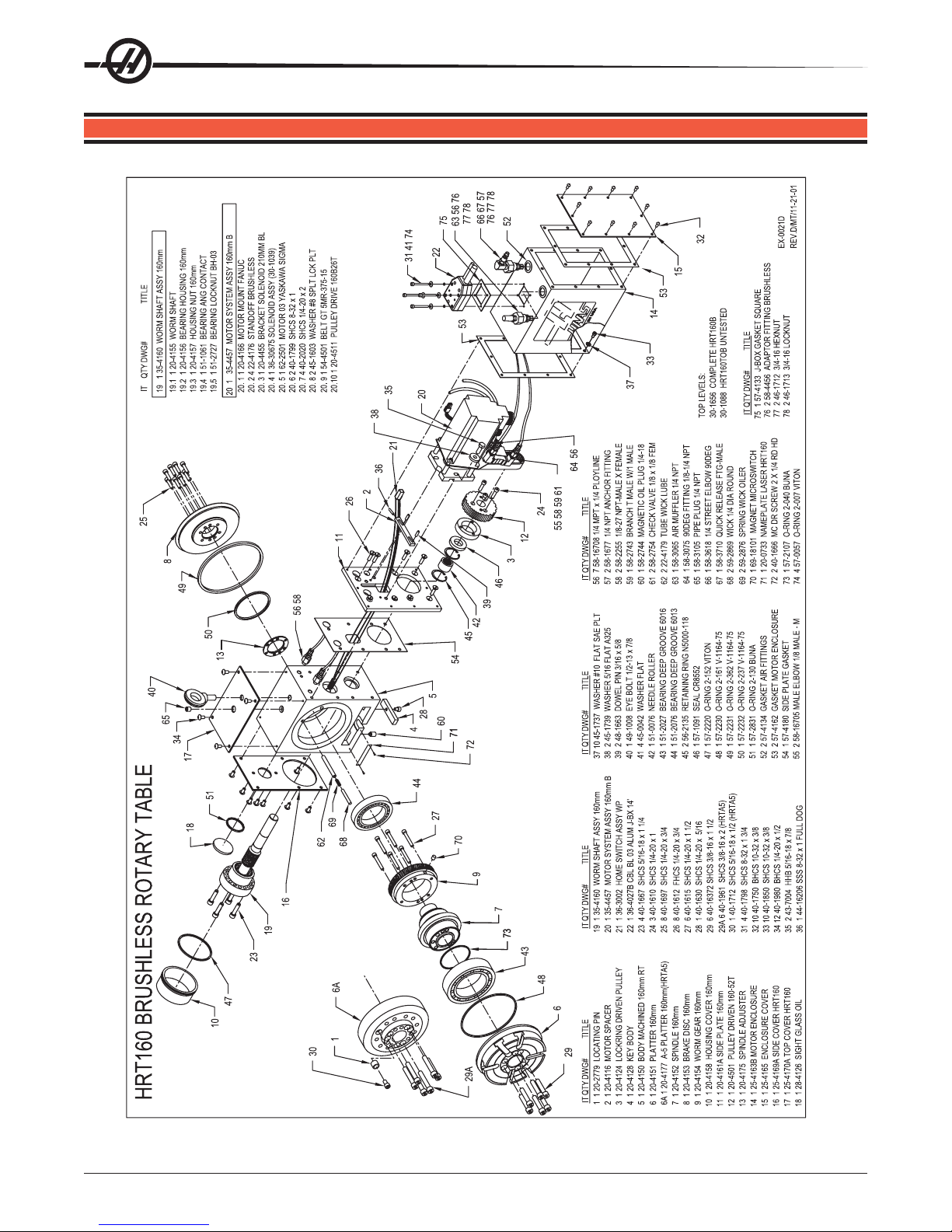
9. HRT ASSEMBLY DRAWINGS
54
96-5047 rev L June 2005

Note: All rotary t ables use Polyurethane tubing for all air lines. S pecifications are: 1/4 O.D. x .160 I.D. 95A Durometer .
96-5047 rev L June 2005
55

HRT210SHS
NOTE: METRIC O'RING SUPPLIED
WITH HARMONIC DRIVE TO BE
24
10
11
37
24
27
29
24
34
39
35
INSTALLED ON FACE OF HARMONIC
DRIVE . (NOT SHOWN IN THIS VIEW)
5
18
4
30
18
38
EX-0028D
REV.D/MT/11-25-2
O-RING, 2-130 BUNA
O-RING, 2-157 BUNA
GASKET, MOTOR ENCLOSURE
GASKET, ENCLOSURE COVER
22
9
33
8
1 57-2831
SEAL CR11615
1 57-4530
1 57-4529
1 57-2875
1 57-4533
313233343536373839
15
7
21
25
28
32
26
14
41
42
23
SHCS, ¼-20 X 5/16
MSHCS, M12 X 45
MSHCS, M5 X 16
SHCS, 5/16-18 X 1
HHB 1/2-13 X 1 SELF SEALING
1 40-1630
43
1 43-1651
1 43-0015
8 40-0010
24 40-1500
161718192021222324
YASKAWA SIGMA MOTOR 09
MAGNET, MICRO SWITCH
HARMONIC DRIVE, 50:1
PIPE PLUG ¼ NPT
MAGNETIC OIL PLUG ¼-18
1 58-3105
1 58-2744
BHCS,10-32 X 3/8
SHCS, 5/16-18 X 3/4
4 40-16385
12 40-1750
1/8 X 1/8 FEMALE CHECK VALVE
1 62-0014
1 69-18101
1 59-4532
1 58-2754
41
40
WASHER BRASS Ø0.314 I.D. X Ø0.420 O.D.
BHCS, ¼-20 X 1/2
SHCS, 8-32 X 1 3/4
WASHER BRASS Ø.328 I.D.X Ø.562 O.D.
3 45-0047
4 45-0039
4 40-1798
28 40-1980
25
26
BHCS 1/4 X 3/8 ZINC
1/8-27 PIPE PLUG
AIR MUFFLER, CENTERED
MALE ELBOW, 1/8
2 40-1633
1 58-1627
1 58-2262
1 58-16705
424344
45
WASHER, #8 SEALING S.S.
O-RING, 2-260 VITON
EYE BOLT, ½-13 X 7/8
O-RING, 2-166
1 57-2127
1 57-2221
1 49-1008
4 45-0042
272829
30
17
20
56
19
1
36
2
24
31
13
45
44
12
6
16
3
40
BODY MACHINING
PLATTER, HRT210SHS
KEY, BODY
1 20-4521
1 20-4520
1 20-4128
123456789
ID QTY DWG# TITLE ID QTY DWG# TITLE ID QTY DWG# TITLE
O-RING 2-007 VITON
MOTOR MOUNT, HRT210SHS
DRIVE SPACER
RETENTION CAP
4 57-0057
1 20-4522
1 20-4523
1 20-4531
ENCLOSURE COVER
SIDE COVER-A
MOTOR ENCLOSURE
1 25-4525
1 25-4526
1 25-4524
101112
MICRO SWITCH ASSY
TOP COVER
SIDE COVER-B
OIL SIGHT GLASS
BL 05 CABLE WP 14'
1 36-3002
1 25-4527
1 28-4126
1 25-4528
14
13
1 36-4029B
15
96-5047 rev L June 2005

96-5047 rev L June 2005
57

58
96-5047 rev L June 2005

I D QTY DWG # DESCRIPTION
1 1 20-4116 MOT O R S P ACER
2 1 20-4230 KEY BODY 310MM/450MM
3 1 20-4250 BODY MACHINED 450mm RT
4 1 20-4251 PLATTER
5 1 20-4252 SPINDLE
6 1 20-4253A FLEX BRAKE
7 1 20-4254 WORM GEAR
8 1 20-4258 HOUSING COVER
9 1 20-4508 PULLEY DIVEN 450-78T
10 1 20-4264 LOCKRING
11 1 25-4265 MOTOR ENCLOSURE
12 1 25-4266 ENCLOSURE COVER
13 1 25-4267A SIDE COVER
14 1 25-4268 TOP COVER
15 1 28-4126 OIL SIGHT GLASS
16 1 35-4454 MOTOR SYSTEM ASSY 450MM B
17 1 35-4245 WORM SHAFT ASSY
18 1 35-4250 ACCUMULATOR ASSY
19 1 35-4255 CHECK VALVE ASSY
20 1 35-4260 HYDRAULIC CYLINDER ASSY
21 1 36-3002 HOME SWITCH ASSY WP
22 1 36-4030B CBL BL ALUM J-BOX 18.5'
23 3 40-1610 SHCS 1/4-20 X 1
24 1 40-1630 SHCS 1/4-20 X 5/16
25 16 40-1980 BHCS 1/4-20 X 1/2
26 16 40-16385 SHCS 5/16-18 X 3/4
27 6 40-16437 SHCS 3/8-16 X 3 1/4
28 6 40-16438 SHCS 3/8-16 X 4
29 8 40-1679 SHCS 1/4-20 X 2 1/2
30 2 40-1696 SHCS 1/4-20 X 4 1/2
31 16 40-1750 BHCS 10-32 X 3/8
32 4 40-1804 SHCS 8-32 X 2
33 20 40-1960 SHCS 3/8-16 X 1 ¾
34 16 40-1632 SHCS 1/4-20 X ½
35 1 40-16391 SHCS 3/8-16 X 1/2
36 3 43-7004 HHB 5/16-18 X 7/8
37 1 44-16205 SSS 8-32 X 1 FULL DOG
38 1 44-1696 SSS 1/2-13 X 3/4 FULL DOG
39 16 45-16390 WASHER 1/4 FLAT SAE PLT
40 1 45-1730 WASHER 3/8 HARD
41 3 45-1739 WASHER 5/16 FLAT A325
42 2 48-1663 DOWEL PIN 3/16 X 5/8
43 1 49-1008 EYE BOLT 1/2-13 X 7/8
44 4 45-0042 WASHER FLAT
45 1 51-0077 NEEDLE ROLLER
46 1 51-2038 BRNG CROSS ROLLER
47 2 56-2083 RETAINING RING N5000-244
48 1 57-0020 O-RING 2-210 VITON
49 1 57-0025 O-RING 2-275 V-1164-75
50 1 57-0094 O-RING 2-384 V-1164-75
51 1 57-0097 O-RING 2-162 VITON
52 1 57-0098 O-RING 2-270 VITON
53 1 57-0101 O-RING 2-373 V-1164-75
54 1 57-2086 SEAL CR19606
55 1 57-2251 O-RING 2-276 V-1164-75
56 1 57-2831 O-RING 2-130 BUNA
57 2 57-4134 GASKET AIR FITTINGS
58 2 57-4261 GASKET ENCLOSURE COVER
59 2 58-16705 MALE ELBOW 1/8 MALE TO MALE
60 4 58-16706 1/8 AIR FITTING STRAIGHT
61 2 58-16708 1/4 MPT X 1/4 POL YLINE
62 2 58-1677 ¼ NP T ANCHOR FITTING
63 2 58-2743 BRANCH T MALE W/1 MALE
64 1 58-2744 MAGNETIC OIL PLUG 1/4-18
65 4 58-2754 CHECK VALVE 1/8 X 1/8 FEM
66 1 58-3065 AIR MUFFLER 1/4 NPT
67 1 58-3075 90DEG FITTING 1/8-1/4 NPT
68 1 58-3105 PIPE PLUG 1/4 NPT
69 1 58-3618 1/4 STREET ELBOW 90DEG
70 1 58-3710 QUICK RELEASE FTG-MALE
71 1 59-2055 3/8" STEEL BALLS
72 1 69-18101 MAGNET MICROSWITCH
73 4 45-1850 WASHER ¼ FENDER PL T
74 4 46-1625 NUT ¼-20 HEX BLK
75 1 28-4278 SIGHT GLASS PRESS GUAGE
76 1 57-4279 GASKET, SIGHT GLASS
77 1 58-2262 AIR MUFFLER CENTERED BRO
78 2 58-16732 1/8X1/8 MALE HEX JOINT
79 4 57-0057 O-RING 2-007 VITON
80 1 57-4133 J-BOX GASKET SQUARE
81 2 40-1666 MC DR SCREW 2 X 1/4 RD HD
82 1 20-0733 NAMEPLATE LASER HRT160
35-4245 WORM SHAFT ASSY
I D QTY DWG # DESCRIPTION
17.1 1 20-4255 WORM SHAFT
17.2 1 20-4256 BEARING HOUSING
17.3 1 20-4257 HOUSING NUT
17.4 1 51-1013 BEARING ANG CONTACT
17.5 1 51-2043 BEARHUG LOCKNUT BH-09
35-4245 CHECK VALVE ASSY
I D QTY DWG # DESCRIPTION
19.1 1 58-16708 1/4 NPT X 1/4 POL YLINE
19.2 1 58-1734 HYD HEX NIPPLE 1/4 NPT
19.3 1 58-27396 DRY GUAGE 2000PSI 1/4NPT
19.4 1 58-2753 HYDRAULIC CHECK V AL VE
19.5 1 58-3695 ¼ NPT FEMALE T
19.6 1 58-1682 NIPPLE ¼ NPT X 2 SST
35-4250 ACCUMULA TOR ASSY
I D QTY DWG # DESCRIPTION
18.1 2 58-1627 1/8-27 PIPE PLUG
18.2 2 58-16732 1/8X1/8 MALE HEX JOINT
18.3 1 58-16700 STREET ELBOW 1/8 INCH
18.4 1 58-1683 LONG NIPPLE 1/8-27 X 3 BRASS
18.5 2 58-27395 AIR PRESSURE GUAGE
18.6 2 58-2740 AIR REGULA TOR
18.7 3 58-3075 90DEG FITTING 1/8-1/4 NPT
18.8 1 58-3100 FEMALE BRANCH T 1/8NPT
18.9 1 59-2736 AIR CYLINDER QJ92-1673
35-4454 M TR S YS TEM ASSY 450MMB
I D QTY DWG # DESCRIPTION
16.1 4 22-4207 STANDOFF
16.2 1 20-4259 MOTOR MOUNTING PLATE
16.3 1 20-4519 PULLEY DRIVE 45600B
16.4 1 25-4269 BRACKET SOLENOID
16.5 1 36-30675 SOLENOID ASSY WP
16.6 1 62-0014 MOTOR 09 YASKAWA SIGMA
16.7 4 40-1629 SHCS 5/16-18 X 2 3/4
16.8 2 40-1799 SHCS 8-32 X 1
16.9 4 45-1600 WASHER 5/16 SPLT LCK PL T
16.10 2 45-1603 WASHER #8 SPL T LCK PL T
16.11 1 54-4508 BEL T GT 5MR-800-15
16.12 1 62-0027 NOK SEAL SIGMA 9 SERIES
35-4260 HYDRAULIC CYLINDER ASSY
I D QTY DWG # DESCRIPTION
20.1 1 20-4270 PRIMARY CYLINDER
20.2 1 20-4271 PRIMARY PISTON 450MM
20.3 1 20-4272 CAP PRIMARY CYLINDER
20.4 1 20-4273A SECONDARY CYLINDER
20.5 1 20-4274 SECONDARY PISTON
20.6 1 56-2084 RETAINING RING N5000-200
20.7 1 57-1036 POLYSEAL 1870-16250
20.8 1 57-1037 WEARBAND W2-2000-375
20.9 2 58-3075 90 DEG FITTING 1/8-1/4 NPT
20.10 1 59-2058 BALL 1/4 STEEL
20.11 1 59-2083 SPRING 31/64 X 4 7/16
20.12 1 58-0058 O-RING 2-014 V-1164-75
20.13 1 57-0096 O-RING 2-133 VITON
20.14 1 57-1038 POLYSEAL 12500250
96-5047 rev L June 2005
59

60
96-5047 rev L June 2005

96-5047 rev L June 2005
61
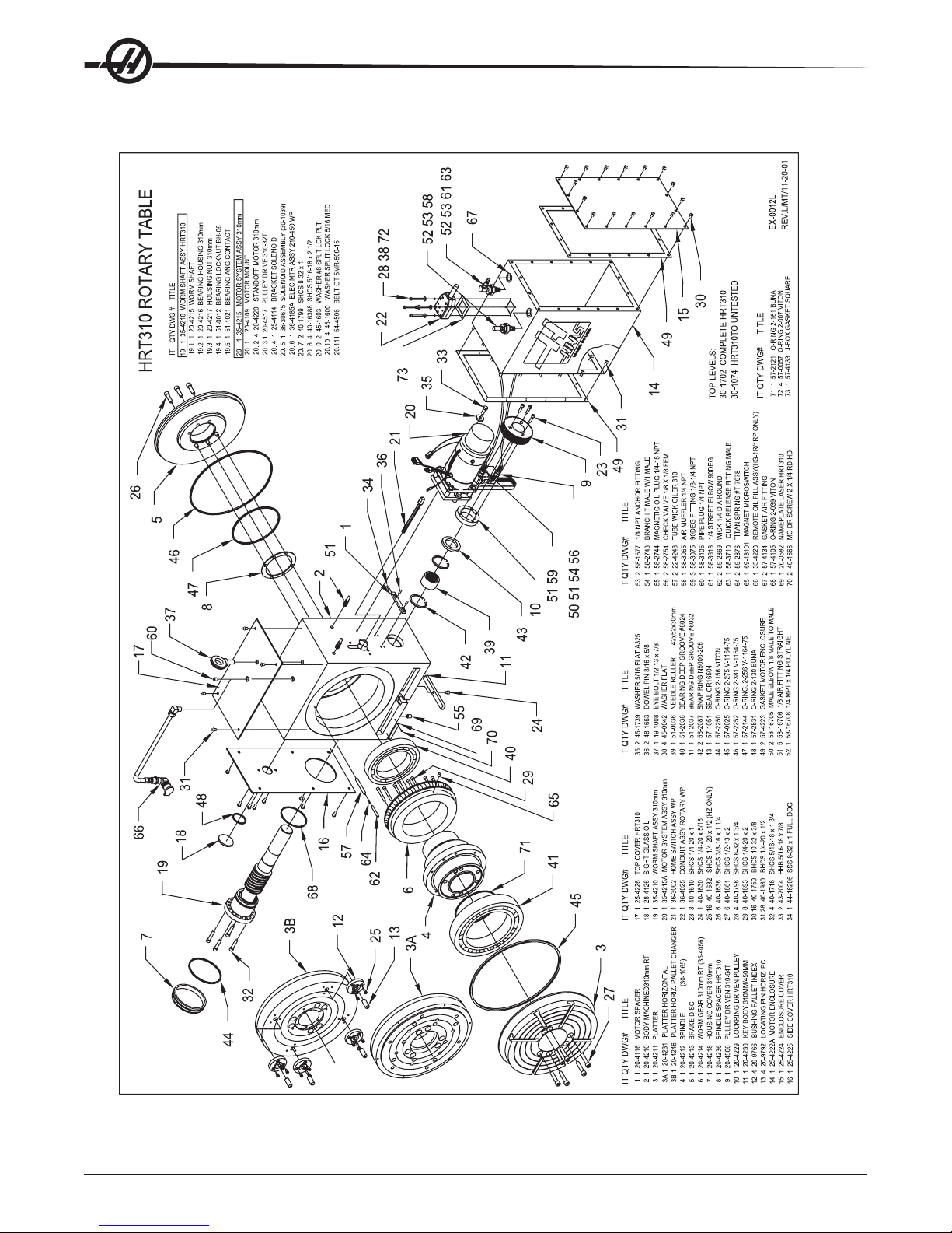
62
96-5047 rev L June 2005

96-5047 rev L June 2005
63

I.D. QTY
. NO.
1 1
2 1 SET
ACE GEAR
3 1
4 1
5 1
SPINDLE INDEXER
6 1
8-32 HEX NUT
7 1
SPINDLE SLEEVE
8 1
WORM GEAR
9 2
10 1
1 1
, 8-32 X 1 FULL
12 1
13 2
14 1
15 1
16 1
CLEVIS PIN 3/16 X 1.25
17 1
BEARING (NYLON)
18 1
SPINDLE SP
19 1
O-RING 2-365
20 1
BRAKE DISC
21 1
SIDE COVER
22 1
23 1
TE + SSS
24 1
CAM LIFT
25 1
SHOULDER BOL
1/4-20 X .375
6 1
PROX. SWITCH
27 1
STR 6
TUBE-4 MP
28 1
1/4 MUFFLER
29 2
ANCHOR 4FP
30 1
QUICK RELEASE FITTING
, MALE RN
31 1
ANCHOR 4FP
32 1
STR 6
TUBE-4 MP
33 1
CROSS 1/8
34 1
ANCHOR 4FP
35 1
ANCHOR FP
36 1
TUBE X 1/8 NPT
37 1
TUBE X 1/8 NPT
38 1
1/4 NPT
MALE HX JOINT
39 1
QUICK EXHAUST
40 1
1/4 STREET
, 90 DEG
41 1
ORFICE FITTING .020
42 1
43 1
STR 6
TUBE-4 MP
44 1
1/4 STREET
, 90 DEG
45 1
TUBE X 1/8 NPT
46 1
CHECK V
47 1
MM ELBOW
48 1
49 1
R BRACKET
50 4
OR, ST
AND OFF
51 1
OOTH PULLEY
, SIGMA
52 1
OR MOUNTING PLA
53 1
SOLENOID V
VE, 5 W
54 1
, ¼ X 1 X .029
55 1
CAM LIFT
See
Sub-Assy.
“D”
See
Sub-Assy.
“B”
See
Sub-Assy.
“C”
See
Sub-Assy.
“C”
DESCRIPTION
20-1912 PLATTER
20-4285 FACEGEAR
57-4283 O-RING
57-2121 O-RING
. DWG. NO.
11
2 1 SET
41
I.D. QTY
31
20-4283 SPINDLE INDEXER
46-1617 8-32 HEX NUT
20-1913 SPINDLE SLEEVE
20-4287 WORM GEAR
51
61
71
81
DOG
51-4285 THRUSTWASHER
51-4286 THRUSTBEARING
44-16206 SET SCREW, 8-32 X 1 FULL
20-4286 LIFT PISTON
10 1
111
12 1
92
57-4282 O-RING
57-0139 O-RING
13 2
14 1
57-2980 O-RING
48-0101 CLEVIS PIN 3/16 X 1.25
57-4288 THRUSTBEARING (NYLON)
15 1
16 1
17 1
ACER
20-4236 SPINDLE SP
57-0381 O-RING 2-365
19 1
18 1
20-4213 BRAKE DISC
25-4902 SIDE COVER
20 1
21 1
20-1914 BODY
20-4116 MOTORADJUSTMENT PLATE + SSS
23 1
22 1
TRIP
20-2457 CAM LIFT
24 1
T 1/4-20 X .375
49-0048 SHOULDER BOL
69-1601 PROX. SWITCH
261
25 1
BODY
TUBE-4 MP
58-3680 STR 6
58-3065 1/4 MUFFLER
58-1677 ANCHOR 4FP
27 1
28 1
29 2
, MALE RN
NUT
58-3710 QUICK RELEASE FITTING
58-1677 ANCHOR 4FP
30 1
31 1
TUBE-4 MP
58-3680 STR 6
58-1676 CROSS 1/8
32 1
33 1
NUT
58-1676 ANCHOR 4FP
34 1
ELBOW
NUT
58-1677 ANCHOR FP
58-3075 1/4 TUBE X 1/8 NPT
35 1
36 1
ELBOW
1/4
MALE HX JOINT
58-3075 1/4 TUBE X 1/8 NPT
58-3691 1/4 NPT
59-2832 QUICK EXHAUST
37 1
38 1
39 1
.
ELBOW,90DEG
58-3618 1/4 STREET
58-0297 ORFICE FITTING .020
58-3657 FMADAPTER
42 1
40 1
41 1
.
ELBOW,90DEG
TUBE-4 MP
58-5680 STR 6
58-16700 1/4 STREET
43 1
44 1
58-16706 1/4 TUBE X 1/8 NPT
45 1
ALVE
58-2754 CHECK V
58-16705 MM ELBOW
47 1
46 1
AND OFF
62-0012 YASKAWASGMG-09A2 AB
25-4291 MOTOR BRACKET
20-4207 MOTOR, ST
49 1
48 1
50 4
09
TE
AY
, SIGMA
ALVE,5W
20-4516 32 TOOTH PULLEY
20-4259 MOTOR MOUNTING PLA
32-0039 SOLENOID V
53 1
52 1
51 1
59-0668 SPRING,¼X1X.029
54 1
TRIP
20-2457 CAM LIFT
55 1
34
31
30
See
28
29
“C”
32
36
35
33
48
51
50
49
52
53
SUB-ASSEMBLY “C”
Sub-Assy.
27
25
26
55
See
Sub-Assy.
13
15
14
12
22
23
“D”
See
13
Sub-Assy.
9
10
9
8
“B”
See
6
“C”
Sub-Assy.
45
55
44
“B”
11
6
25
54
SUB-ASSEMBLY “D”
16
46
47
SUB-ASSEMBLY
20
19
18
17
21
64
5
4
3
2
1
39
37
43
42
41
40
38
SUB-ASSEMBLY “A”
96-5047 rev L June 2005
 Loading...