

Page 1
Art. No.0499132299030
V09 G22
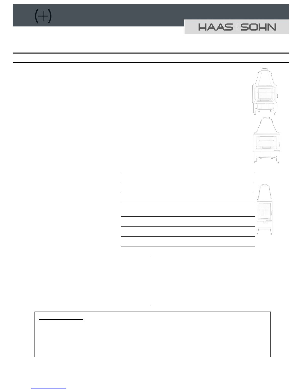
Fireplace inserts EN13229-W
Installation and Operating Manual
Nameplate:
Our supply program: Oil heaters
Chimney stoves
Pellet stoves
Glazed tile and slow-burning stoves for wood and coal
Slow-burning stoves and cooking stoves for wood, coal and
oil
Fireplace inserts for wood
Accessories for stove and fireplace
Accessories for central oil supply
Air humidifiers
HAAS+SOHN Sales & Distribution in Germany
OFENTECHNIK GMBH HAAS+SOHN Ofentechnik GmbH
Urstein Nord 67 Herborner Straße 7-9
A-5412 Puch D-35764 Sinn
Phone:0043 (0) 662 44955-0 Telephone: 0049 (0) 2772 5010-0
Fax: 0043 (0) 662 44955 210 Facsimile: 0049 (0) 2772 5010-99
eMail: office@haassohn.com eMail:info@haassohn.com
http://www.haassohn.com
Important notes:
- Inform your district chimney sweep or district master chimney sweep!
- Please thoroughly read the Installation and Operating Manual!
- Observe the regulations and instructions provided in it when installing and operating the
fireplace insert!
- Please keep this Manual in a safe place!
- The enclosed Equipment Sheet is part of this Installation and Operating Manual.
1
Page 2

TABLE OF CONTENTS
1.DESCRIPTION 3
2. GENERAL INSTRUCTIONS, SAFETY
INSTRUCTIONS 3
3. COMBUSTION AIR SUPPLY: 3
4. SUITABLE CHIMNEY: 4
5. DATA FOR CHIMNEY CALCULATION: 4
7. INSTALLATION OF FIREPLACE INSERT AND
CONNECTION TO THE CHIMNEY 5
7.1 Connecting piece (flue gas pipe): 5
7.2 Protection of installation ceiling (floor): 5
7.3 Floor in front of the fireplace insert: 5
7.4 Chimney connection: 6
7.5 Primary walling and heat insulation of the
back and side walls: 6
7.6 Necessary primary walling and heat
insulation: 6
7.7 Permissible heat insulation and primary
walling material (minimum requirements) : 7
8. INSTALLATION OF THE FIREPLACE INSERT:7
8.1 Expansion joint: 7
8.2 Covering: 7
8.3 Convection air openings: 7
8.4 Convection air space: 7
8.5 Ornamental beams: 8
8.6 Fire protection within the radiation range: 8
8.7 Fire protection outside the radiation
protection: 8
9. INSTALLATION DRAWING: 9
10. OPERATION OF FIREPLACE: 9
10.1 Suitable fuels: 9
10.2 Combustion air supply: 10
10.3 Convection air: 10
10.4 Fire protection outside the radiation range:
10
10.5 Fire protection within the radiation range:
10
10.6 Protection against burns: 10
11. USE AND START-UP: 10
11.1 Initial start-up: 10
11.2 Lighting: 10
11.3 Maximum fuel charge quantity of
approximately 1 hour: 11
11.4 Air setting with closed operation: 11
11.5 Adding fuel: 11
11.6 Operating mode in the transition period: 11
11.7 De-ashing: 11
12. CLEANING AND CARE: 11
13. WARRANTY: 11
13.1 General 11
13.2 Warranty directives: 12
2. HAAS + SOHN does not accept any guaranty
for damages and defects on equipment or their
parts caused through: 12
13.3 Complaints: 12
14. INSTRUCTIONS FOR ORDERING
REPLACEMENT PARTS: 12
Congratulations! You are the owner of a HAAS +
SOHN fireplace insert, a quality product. Please
read the Operating Manual carefully. You will find
information about how to use and operate your
chimney stove which will enable you to increase
the practical value of the device and extend its
working life. In addition you can save fuel by
burning it correctly and protect the environment.
The accompanying Equipment Sheet is part of this
Operating Manual.
Please keep this Manual with the Equipment Sheet
in a safe place so that you can refamiliarise
yourself with the correct operation of your chimney
stove at the start of every heating period.
We can only guarantee our products if you adhere
to the following guidelines of this Installation and
Operating Manual.
2
Page 3

1.Description
Fireplace inserts are highly suitable for the heating
of living and working rooms.
The stove body consists of a welded steel
structure. At the bottom is a wood storage
compartment and above it the ash box, on top of
that the firebox and a heat exchanger at the top.
Between the latter the smoke gas draughts are
arranged above the firebox.
Heating the room air and creating a comfortable
living climate in connection with a covering is
substantially achieved through convection heat.
Because of this you can rapidly heat even cool
rooms that have not been heated for an extended
period of time. The room air enters the wood
storage compartment, is heated in the convection
duct between inner body and outer wall as it rises
and flows out again through openings provided at
the top of the stove. The component of radiation
heat is obtained through heat radiation in the area
of the view window of the firebox door from the
metal surfaces of the stove and - if available - from
the ceramic surfaces on the sidewalls.
2. General instructions, safety instructions
Adhere to national and European standards, local
regulations, planning and building regulations as
well as fire safety regulations. When installing your
stove you must observe the fire prevention
regulations and the national building regulations
applicable at the place of installation in agreement
with the responsible master chimney sweep of the
district. He will also inspect the appropriate
connection of the device to the chimney.
Prior to installation, verify that the carrying capacity
of the substructure is suitable to support the
heating insert. If the carrying capacity is
insufficient, suitable measures (e.g. slab for load
distribution) have to be taken to achieve this.
Your fireplace insert has been subjected to all
inspections required by the legislator. It meets the
specified characteristics in terms of firing efficiency
and smoke gas emissions.
Your fireplace insert of design 1 described in this
Manual has been tested according to DIN 18895
("Fireplace inserts for solid fuels") and EN13229.
The fireplace inserts of design 1 (see Equipment
plate) may be connected to a multiple-use chimney
if the chimney dimension according to DIN 4705
Part 2 allows this.
The fireplace insert is a limited time burning
fireplace.
Basic requirement:
- Ensure that the entire structure, i.e. also
connecting pieces and chimney, are
operationally safe and fireproof and can be
cleaned without effort!
Place of installation:
- Fireplace inserts must only be installed in
rooms and in places where, according to
position, structural circumstances and type of
use no hazards will develop. In the installation
area of the covered heating insert no electrical
wiring must be present in walls and ceilings. In
particular there must be an adequate inflow of
air for combustion in the installation rooms.
The surface area of the installation room must
be configured and of a size that allows proper
operation of the fireplace.
- Fireplace inserts must not be installed in:
staircases (except in residential buildings with
more than two apartments); generally
accessible hallways; rooms in which easily
flammable or explosive substances or mixtures
are processed, stored or produced in such a
quantity that hazards are created through
ignition or explosion; rooms or apartments
from which air is removed through ventilation
systems or warm air heating systems with the
help of fans, unless the operation of the open
fireplace without danger is ensured.
- The operation of open fireplaces is not
threatened if the systems circulate air only
within a room, the systems have safety
devices which automatically and reliably
prevent vacuum in the room of installation or
the volumetric combustion airflows required for
the fireplace inserts and the volumetric flows of
the ventilation systems despite adjustment or
removal of easily accessible control devices of
ventilation systems altogether will not bring
about a vacuum in the installation rooms of the
fireplace inserts and the rooms of the
combined ventilation greater than 4 PA.
3. Combustion air supply:
Ensure that the fireplace will have a minimum
inflow of 360 m³/h of combustion air per each m² of
firebox opening from the outside. Ask your master
chimney sweep responsible for your district.
Installation rooms of fireplace inserts must:
- Have at least one door into the open or which
are connected with other rooms of this type.
Only rooms of the same apartment or
utilization unit apply. If this is not sufficient, the
installation room must have a combustion
airline leading into the open and the firebox
opening with at least 360 m³/h of combustion
air for each m². If there are other fireplaces in
the same combustion air system, there must
3
Page 4
be a minimum inflow to the heating inserts of
540 m³/h of combustion air for each m² of
firebox opening and additionally at least 1.6 m³
of combustion air per hour for other fireplaces
and for each kW of total rated heat output with
a calculated pressure differential of 4 Pa
relative to the outside. (Not considered are
fireplaces which are independent of room air,
do not require a flue gas system or are located
in rooms from which the operational safety of
the heating inserts cannot be endangered).
- We recommend feeding the fireplace insert
with combustion air in the area of the
convection chamber.
- In accordance with the national building
regulations, combustion airlines in buildings
with more than two full storeys and combus tion
airlines bridging firewalls shall be established
such that fire and smoke cannot be transmitted
to other storeys or fire sections.
- When designing the combustion airlines,
resistances have to be taken in account which
in particular applies to the installation of bends
and deflections or long lines.
4. Suitable chimney:
Before installing the heating insert the responsible
master chimney sweep for the district must be
informed. Should the fireplace insert be connected
to an already existing chimney, the latter has to be
swept and checked by the chimney sweep for
condition and tightness. He would also establish if
the chimney is suitable for connecting the heating
insert.
If no chimney is present or the existing chimney is
not suitable, the master chimney sweep for the
district determines the dimensions of the chimney
to be newly erected according to DIN 4705 Part 1
and Part 2.
The effective chimney height starting from the flue
gas inlet must be at least 4 m.
5. Data for chimney calculation:
The following data apply for dimensioning the chimney according to DIN 4705:
Operation with closed firebox:
Insert
Esprit
185.16
NHO
Insert
Esprit
185.16
Part
load
Insert
Trend
184.18
NHO
Insert
Trend
184.18
Part
load
Inserts
Komfort
180.18 +
Prestige
181.18 +
Exquisit
182.18
NHO
Inserts
Komfort
180.18 +
Prestige
181.18 +
Exquisit
182.18
Partload
Insert
Opus
186.18-1
NHO
Inserts
Opus
186.18-1
Part load
Net heat output 7 8 8 8 kW
Heat output area 8 3,7 8,5 4,6 9,2 4,7 8,5 4,5 kW
Flue gas mass flow 7 6,12 8 6,8/7,9 g/s
Mean flue gas connector temperature 290 272 330 320
o
C
Efficiency 80,7 83,2 81,7 80,3 %
CO 0,09 0,08 0,08 0,1 %
Minimum delivery pressure at rated
heat output
12 12 12 12/15
Pa
Minimum delivery pressure at 0.8
times the rated heat output
10 9 10 10/12
Pa
No data is listed for operation with open firebox since your fireplace insert must only be operated with the selfclosing door (A 1).
4
Page 5

6. Room heating capacity according to DIN 18893:
In this regard, please note the details on the Equipment sheet.
The values relate to rooms which do not correspond to the heat protection regulations. For rooms with a room
volume in excess of 200m
3
a heat requirement calculation according to DIN 4701 has to be carried out.
Insert
Esprit 185.16
Inserts
Komfort 180.18,
Prestige 181.18,
Exquisit 182.18
Trend 184.18
Opus 186.18
The rated heat output stated
on the equipment
plate with
7 kW 8 kW
- favourable 144 186 m
3
- less favourable 84 107 m
3
- unfavourable
Heating conditions are
adequate for:
56 73 m
3
7. Installation of fireplace insert and connection to the chimney
7.1 Connecting piece (flue gas pipe):
The connecting piece has to be technically
matched to chimney and fireplace insert and be
designed to suit the requirements of DIN 18160
Part 2.
In the case of metal connecting pieces the wall
thickness must be at least 2 mm.
If the connecting piece penetrates components
with combustible building materials (e.g. walls to
be protected), protective measures according to
DIN 18160 Part 1 and Part 2 have to be taken.
7.2 Protection of installation ceiling (floor):
Installation ceilings without adequate transverse
distribution (e.g. wooden ceilings) must be
protected through an additional 6 cm thick proven
concrete slab and a 6 cm thick heat insulation
layer according to AGI Working Sheet Q 132 in the
area of the heating insert. We recommend you
seek advice from a structural engineer.
If the installation floor has adequate transverse
distribution a 6 cm thick heat insulation layer is
sufficient.
7.3 Floor in front of the fireplace insert:
In front of the heating insert the floor of
combustible materials has to be protected through
a sufficiently thick covering of non-combustible
materials or replaced. The minimum dimensions of
this non-combustible area in front of the firebox
opening are:
To the front in accordance with the height (H) of
the firebox floor above the floor plus 300 mm.,
however at least 500 mm.
To the sides, in accordance with the height (H) of
the firebox floor above the floor plus 200 mm,
however at least 300 mm.
5
Page 6

7.4 Chimney connection:
If the existing chimney does not have a suitable
shaped connection piece for the fireplace insert a
subsequent connection has to be established. The
chimney connection height is obtained from the
correctly placed fireplace insert plus fitted smoke
gas bend and connecting piece, measured from
the upper edge of the support plate to the centre of
the connecting pipe in the inlet area of the
connection point. Please take into account the
necessary distances for primary walling, heat
insulation, expansion joint etc.
7.5 Primary walling and heat insulation of the
back and side walls:
Once a suitable chimney connection piece has
been installed the required primary walling and
heat insulation can be carried out.
7.6 Necessary primary walling and heat insulation:
The required minimum heat insulation in front of components to be protected was established during the
testing of the fireplace inserts Haas + Sohn according to DIN 18895 and EN 13229. The following protective
measures were determined:
Fireplace insert
ESPRIT 185.16
Fireplace
insert Op s
u
186.18
Fireplace inserts
KOMFORT 180.18,
PRESTIGE 181.18,
EXQUISIT 182.18,
TREND 184.18
Thickness in mm
Back wall
100
100
100
Primary walling
Side wall
100
100
100
(Primary walling replacement,
insulating material according
to AGI Q 132)
Room ceiling within
covering
60 60 60
Floor
40
40
Side wall
120
40
Termax
SN 400
120
Back wall
120
40
Termax
SN 400
130
Convection air ceiling
/intermediate ceiling
110 120 120
Heat insulation layer
Flue gas pipe outside the
convection jacket
60 60 60
1. Primary walling: 10 cm thick mineral primary
walling must be erected directly on the building
wall (back wall and if applicable side wall) to
be protected. The primary walling must be
erected up to the insulation layer and the
building wall to be protected, however protrude
at least 20cm over the connecting piece (flue
gas pipe). Primary walling can be omitted if the
building wall is at least 10cm thick and
consists of non-combustible components and
is not a carrying reinforced concrete wall.
2. Room ceiling above the heating insert (primary
walling replacement): If the cavity or the
covering above the fireplace insert reaches up
to the room ceiling this must be protected if it
consists of combustible materials or serves as
a carrying element. The protection consists of
an at least 6 cm (better 10 cm) thick heat
insulation layer (insulating material code
number: 12.07.21.75.11 according to AGI Q
132). This protective measure is
recommended as load-bearing intermediate
ceiling (e.g. of plate) with heat insulation layer
arranged on top.
3. Heat insulation: Convection jacket and
convection hood (external equipment shape)
must be covered with a heat insulation layer
on all sides. The heat insulation must be butt
joined without any gap and installed in an
overlapping arrangement on the sides. If these
insulation panels are not held by walls,
coverings or adjoining panels, these shall be
attached at a distance of approximately 30 cm.
The room-side covering (apron) need not be
heat-insulated if the heating insert design is
such that the free surfaces of the covering and
the surfaces of the recesses for fuel storage
can heat to a maximum of 85°C. In the case
of surfaces of mineral building materials,
except surfaces on which items can be placed,
the value of 85°C is replaced with the value of
120°C. The heat insulation layers of mineral
wool or comparable must be tightly covered
towards the installation room and convection
air room to prevent flying fibres.
6
Page 7

7.7 Permissible heat insulation and primary
walling material (minimum requirements) :
1. Insulation materials: Insulation materials
according to AGI working sheet Q 132:
12.07.21.70.09 (=insulation material code
number).
This means: Insulation material group 12, Type:
stone wool,
Form of delivery group 07, Shape: Tiles,
Heat conductivity Group 21, Supply form:
G.-Curve 2
Upper application limit temperature
Group 70 corresponds to 700°C
Rated pipe density Group 9 corresponds to
90 kg/m³
2. Primary walling:
Brick tiles according to DIN 105 Part 1 and
Part 3
Bricks according to DIN 106 Part 1, DIN
4163, DIN 18151 or DIN 18152
Wall building tiles according to DIN 4166,
DIN 18162 or DIN 18163
3. Alternative primary walling and insulating
materials:
These are approved by the German Institute for
Building Technology, Berlin (DIBt). They also
mostly meet the material requirements of heat
insulation and primary walling. Details on these
building materials can be obtained from your
specialist suppliers.
8. Installation of the fireplace insert:
Once the heat insulation has been carried out
according to the insulation instructions, the
fireplace insert can be placed on the prepared
surface. Align the fireplace insert with the adjusting
screws and connected to the chimney using the
connecting piece (smoke pipe).
The chimney connection must be carried out in
keeping with DIN 18160 Part 1 and Part 2 (see
Page 5, Paragraph 7.1).
8.1 Expansion joint:
An expansion joint must be provided between
insert and covering which is closed with sealing
cord or sealing band.
8.2 Covering:
The covering of the fireplace insert on the room
side must consist of non-combustible
materials of fire protection Class
A1 (e.g. glazed bricks, plaster on
plaster substrates, metal or ceramic
oven tile). There must be no direction
connection between
covering and fireplace
insert.
Caution! The covering of
the chimney apron must
only rest on a separate support
frame which is normally mounted to the wall.
8.3 Convection air openings:
The free non-obstrutable cross section for the air
inlet and air outlet openings must be at least 600
cm
2
each.
Caution: After the installation of the entire chimney
neither the convection air inlet nor the outlet must
be obstructed by any components whatsoever. To
avoid heat congestion, convection air inlet and
outlet openings or grilles have to be always open
during heating operation. No closable grilles, fins,
louvers and the like may be installed in such
openings. Convection air cross sections between
heating insert and covering as well as rear
insulation: free minimum distance between
fireplace insert and lateral covering of noncombustible material: 50mm.
Free minimum distance between fireplace insert
and rear insulation or placement wall of noncombustible material: 100mm.
Note: The minimum distance stated above must be
maintained over the entire height of the fireplace
insert over the entire width in each case so that the
convection air is able to flow through freely.
8.4 Convection air space:
Since the fireplace insert does not have a
prefabricated convection air chamber device a
distance to both sides of 60 mm must be taken into
account between fireplace insert and heat
insulation layer. The heat insulation layer as
radiation protection equaliser and protection
against flying fibres must be covered with a tight
sheet metal jacket of galvanized sheet metal.
The convection air openings must at least meet
the cross section mentioned above.
7
Page 8

8.5 Ornamental beams:
Ornamental beams in front of the covering of
the fireplace insert are permissible at a
distance of at least 1 cm if the ornamental
beam is not part of the building and the
intermediate spaces to the covering are clear
so that no heat congestion can develop and
the ornamental beam is not located in the
radiation range of the fireplace insert.
Figure:
1 = Fireplace
insert
2 = Expansion
joint
3 = Covering
4 = Ornamental
beam
5 = Support frame
6 = Radiation
protection
8.6 Fire protection within the radiation
range:
At least 80 cm distance has to be maintained
from the firebox opening to the front and to
the sides (6). If radiation protection that is
ventilated on both sides is arranged, a
distance of 40 cm is sufficient.
8.7 Fire protection outside the radiation
protection:
From the outer surfaces of the covering of the
fireplace insert at least 5 cm distance to
combustible components must be maintained.
The intermediate space must be open for
airflow so that no heat congestion develops
(8).
Components which cover only small areas of
the fireplace insert covering such as floors,
butt-joining wall coverings and insulation
layers on ceilings and walls may be joined up
to the covering without spacing (9). Other
wider, strip-shaped and combustible
components such as ornamental beams are
permissible at a distance of 1 cm from the
covering of the fireplace insert (see
ornamental beam).
8
Page 9

9. Installation drawing:
fireplace insert according to DIN 18895 /EN13229 without factory-made convection air jacket
1. Ceiling to be protected of combustible
components or as carrying building
element
2. Substitute material:
Carry out heat protection measure
according to DIN 18160
4. Connecting pieces of steel plate
5. Heat insulation layer:
Rear wall (see Page 5),
Side wall ceiling (see Page 5),
Convection air chamber (see Page 5)
6. Primary walling
7. Wall to be protected of combustable
building materials or carrying building
element of concrete or reinforced
concrete
8. Combustion air supply
9. Outside airflap
10. Heat insulation layer
11. Support plate
12. Installation floor to be protected of
combustible building materials or carrying
building element
13. Shielding floor protection of noncombustible building materials
14. Convection air inlet (circulating air)
15. Covering
16. Fireplace insert
17. Support frame
18. Ornamental beam
19. Throttle valve
21. Air outlet grille
22. Support element
23. Heat insulation layer (primary walling
substitute) 6 cm thick
24. 80 cm radiation ran ge
25. Sheet metal covering convection air
chamber
10. Operation of fireplace:
The fireplace inserts of Haas + Sohn with self-closing door have the designation fireplace insert EN13229-W
Design 1 which means they are only suitable for operation with closed fire box and must only be operated with
closed firebox.
In the case of stoves of Design 1 the closing springs of the firebox door must not be removed if such a device
is connected to a chimney with multiple connections. The inclusion in Design 1 is defined by the self-closing
firebox doors. The firebox doors must only
be opened only to charge fuel and for removing ash. Otherwise
these must be kept closed even if the stoves are not operated in order to avoid interference with other
fireplaces and hazards connected with this.
10.1 Suitable fuels:
The fireplace inserts must only be operated with the following fuels and closed firebox:
• Plain dry billet wood
• Wood briquettes according to DIN 51 731 HP 2
9
Page 10

Caution! Wood it not a slow-burning fuel so that
continuous heating of the fireplace with fuel
overnight is not possible.
The fireplace insert is intended for the burning of
dry billet wood with a maximum water content of
30% of the dry weight. Billet wood should be
stored in airy and dry places for 2 years.
Excessively moist wood increasingly results in
smouldering with tar and condensate formation
which can damage the chimney. At any rate,
excessive device contamination occurs. The billet
wood length should be around 33 or 50 cm.
If incorrect or excessively moist fuel is used a
chimney fire can occur because of deposits in
the chimney. Immediately close all air
openings in the stove and inform the fire
brigade. Once the chimney has burnt out have
it inspected for cracks or leaks by an expert.
Wood is a highly de-gassing fuel and requires a lot
of top air (secondary air). Light or slow-burning
control with this fuel is not possible. The heat
output in the combustion of wood is always
determined by the amount charged.
Firing of properly dried wood is the most
economical and most environmentally friendly
combustion since the calorific value of fresh wood
is substantially less than that of dry wood.
The burning of waste, especially plastic, packaging
material, coated and treated wood harms your
fireplace insert and is additionally prohibited by the
Federal Emission Protection Law. Brush wood,
paper and small wood pieces must only be used
for lighting.
Caution: Never use easily combustible liquids
such as petrol, spirits for lighting and always
keep such liquids away from your fireplace
insert.
10.2 Combustion air supply:
With both the open and closed operation of the
fireplace carries a high demand for fresh air. Do not
change existing precautions for combustion air
supply. Ensure that the necessary combustion
airlines are open while the fireplace is operated.
10.3 Convection air:
To avoid heat congestion the convection air inlet
and outlet grilles must always be open during
heating operation.
10.4 Fire protection outside the radiation
range:
No objects of combustible building materials (e.g.
shelves) must be placed closer to the open fireplace
than a distance of 5 cm.
10.5 Fire protection within the radiation range:
Seen from the firebox opening forward and to the
sides, no combustible components must be
present (e.g. furniture, carpets, flowers etc.) in a
range of at least 80 cm.
10.6 Protection against burns:
It is imperative to note that there are hot surfaces or
operating handles present on heating devices which
are in operation. Please use the enclosed protective
glove to operate the fireplace. Presence in the 80
cm radiation range is only advisable to charge the
fuel, prolonged presence there can result in skin
burns. Keep children away from fireplaces in
operation.
When operating the device ensure that adequate air
is supplied to the room from the outside.
11. Use and start-up:
11.1 Initial start-up:
When using the fireplace insert for the first time
burn it with moderate output to avoid possible
damages due to heating it up too quickly
(especially drying of the refractory brick lining). On
initial heating, smell and smoke will develop due to
the curing of the surface coating. Ensure the room
is well ventilated during initial start-up.
11.2 Lighting:
The fireplace insert is charged with fuel through
the firebox door.
Initially place 3 to 4 wood billets (approx. 2.0 to 2.5
kg) on the firebox floor or grate, uncoated paper on
top, cardboard or an igniting cube, brushwood,
small wood pieces or briquette pieces on top of
this. Open all existing air control dampers to the
maximum. After igniting, close the firebox door.
Then set the air control dampers in accordance
with the instructions on the enclosed Equipment
Sheet.
Your fireplace insert is equipped with a typical
design flat firing system which means that only one
layer of fuel must be charged on the basic embers.
Please note that the quantity, the size of the
pieces and the kind of the wood charged has a
direct influence on the heat output.
When feeding excessive fuel quantities your fire
insert can be heated in excess of what is intended
by the design. This can damage the fireplace
insert, other parts of the chimney of the building
itself. Never charge more than the stated fuel
quantities at one time on the existing basic
embers.
10
Page 11

11.3 Maximum fuel charge quantity of approximately 1 hour:
Total quantity Fuel Quantity
Esprit
185.16
Komfort 180.18, Prestige 181.18,
Exquisit 182.18 Trend 184.18, Opus
186.18
Billet wood 2 – 3 billets 2,0 kg 2,5 kg
Wood
briquettes
4 – 5 small pieces
(Divide large briquettes if required)
1,8 kg 2,1 kg
11.4 Air setting with closed operation:
The fireplace inserts of Haas + Sohn have an
adjustable air damper. The required combustion
air enters as primary air through the grate and the
lateral ducts and the firebox as window flushing air
above the firebox door.
11.5 Adding fuel:
In addition to the use of suitable fuel and
adequate fuel draught the manner in
which the fireplace is operated also has
major influence on keeping the view
window clean. In this connection we
recommend to charge only one layer of
fuel, to use preferably long (approx.. 33 or
50 cm) which largely fill the firebox width.
Briquettes should be arranged in the
firebox so that they preferably fill one layer
(approx. 5 to 10 mm distance between the
briquettes).
Caution! Add additional fuel only on the basic
embers (no flames present).
Approximately 5 to 10 seconds before opening the
firebox door completely close the primary air
damper or dampers (see Equipment sheet) to
prevent the leaking of smoke gases from the
combustion chamber into the living room. Having
charged the fuel, please close the firebox door
again. After this, immediately set all air dampers to
maximum opening to keep the time span to the
igniting of the fuel as short as possible. As soon
as the fuel burns lively re-establish the control
setting as described on the enclosed Equipment
Sheet.
11.6 Operating mode in the transition period:
In the transition period or with elevated outside
temperatures, problems with the chimney draught
can occur in the event of a sudden temperature
increase so that the flue gases are not fully
extracted. For this reason, always operate the
stove in the transition period only with the least
amount of fuel possible in order to be able to
improve the combustion and draught situation in
such cases by opening the air dampers.
11.7 De-ashing:
Following prolonged burning, at least once per
day, remove the ash with the help of a poker
through the grate in the ash box and empty the
ash box. This is best done in the morning after the
embers has left the fireplace in a relatively cold
state. Please ensure that the ash box is emptied
when approximately half full so that the ash cone
does not grow up too closely to the grate.
If the grate is packed in the ash cone there is a risk
that it is damaged through overheating since it
cannot be circulated by any air.
Caution!
Before emptying ash always ensure that there is
not residual embers in the ash. Even if the ash is
cold remnants of embers may still be present and
result in a fire in a waste container.
Wood ash can be composted and used as
fertilizer.
12. Cleaning and care:
At least once per year, if required more frequently,
clean and look after your fireplace insert in the cold
state. When doing so, remove the ash deposits in
the smoke pipe and on the smoke deflection plates
or draught deflection plates. Draught deflection
plates of vermiculite can be removed for cleaning
(see Equipment sheet). Please reinstall these
carefully in the same position after cleaning. For
cleaning the smoke gas draughts an ash extractor
with fine particle filter is best suitable. Dirt on the
view windowpane is best and most
environmentally friendly removed with a scouring
pad moistened in water which you dip in the wood
ash or other domestic glass cleaners. The chimney
must likewise be regularly cleaned by the chimney
sweep.
Your master chimney sweep will inform you on the
necessary intervals.
The chimney stove should be checked by an
expert once per year.
13. Warranty:
13.1 General
HAAS + SOHN accept three years guarantee for
this device within the scope of the warranty
directives with the exception of parts which are
directly exposed to the fire (wear parts). The
guaranty commences on the day of delivery. The
invoice must be presented as proof.
11
Page 12

13.2 Warranty directives:
1. HAAS + SOHN accept guaranty for the duration
of three years calculated from the delivery to the
end user for
a) unobjectionable material condition and
workmanship to suit the purpose,
b) expert assembly,
c) Adherence to the rated heat output (watt)
according to DIN 18895/ EN 13229 and the
room heating capacity according to DIN 18893
(see Equipment plate, technical data on the
enclosed Equipment sheet or catalogue
details).
The warranties a) to c) extend to the repair of the
device or the parts subject of the complaint free of
charge. Entitlement exists only for the free of
charge replacement of parts having defects in the
material and in the workmanship. Claims beyond
this are excluded.
We provide 6 months guaranty for wear parts in
the fire area such as refractory, vermiculite, fire
grate, glass ceramic and seals as well as
operating elements such as handles and painted
surfaces.
2. HAAS + SOHN does not accept any guaranty for
damages and defects on equipment or their parts
caused through:
• External, chemical or physical effects during
transport, storage, installation and utilisation of the
device (e.g. quenching with water, food cooking
over, condensate, overheating due to incorrect
operation (e.g. open firebox door), or hair crack
formation in natural stones or enamelled parts are
not considered a quality defect,
• Incorrect choice of chimney stove size,
• Failure to heed the building regulations applicable
from time to time,
• Errors in the installation and connection of the
device,
• Insufficient or excessive chimney draught,
• Incorrectly performed repair operations or other
especially subsequent changes to the fireplace or
flue gas pipe (smoke pipe and chimney),
• Use of unsuitable fuels,
• Incorrect operation: Overloading the devices (see
Operating Instructions of the manufacturer)
• Wear on the parts of steel, glass ceramic seals,
refractory or vermiculite directly exposed to the
flames insofar as not included in the warranty (1a),
• Incorrect treatment,
• Insufficient care, use of unsuitable cleaning agents.
13.3 Complaints:
Please present your complaints only to your
specialist dealer. When doing so, it is
imperative that you should name the type
and manufacturing number of your chimney
stove. This information can be found on the
nameplate of the device (in the wood
storage compartment of the device).
14. Instructions for ordering replacement parts:
When ordering replacement parts please state the
complete type and manufacturing number of your
chimney stove. These details can be found on the
nameplate of the device (in the wood storage
compartment of the device).
Also pay attention to the technical drawings and
tables on the Equipment Sheet where you will find
the correct designation of the required
replacement parts. For ordering refractory
replacement parts, the refractory bricks in these
drawings are numbered and the refractories are
viewed from the top in these drawings (top view).
Caution! Do not change the fireplace!
Use only replacement parts that have been
expressly approved or are offered by the
manufacturer.
If required, please contact your specialist dealer.
12
 Loading...