

Page 1

Haas Technical Publications
Manual_Archive_Cover_Page Rev A
any other party automatically voids the factory warranty.
June 6, 2013
HAAS SERVICE AND OPERATOR MANUAL ARCHIVE
VF-Series Service Manual 96-7045 English November 26 1993
• This content is for illustrative purposes.
• Historic machine Service Manuals are posted here to provide information for Haas machine owners.
• Publications are intended for use only with machines built at the time of original publication.
• As machine designs change the content of these publications can become obsolete.
• You should not do mechanical or electrical machine repairs or service procedures unless you are qualied
and knowledgeable about the processes.
• Only authorized personnel with the proper training and certication should do many repair procedures.
WARNING: Some mechanical and electrical service procedures can be
extremely dangerous or life-threatening.
Know your skill level and abilities.
All information herein is provided as a courtesy for Haas machine owners
for reference and illustrative purposes only. Haas Automation cannot be held
responsible for repairs you perform. Only those services and repairs that are
provided by authorized Haas Factory Outlet distributors are guaranteed.
Only an authorized Haas Factory Outlet distributor should service or repair a
Haas machine that is protected by the original factory warranty. Servicing by
Page 2

VF Series Service Manual
TROUBLESHOOTING
This section is intended for use in determining the solution to a known problem. Solutions given are
intended to give the individual servicing the CNC a pattern to follow in, first, determining the problem's
source and, second, solving the problem.
The troubleshooting tips are organized in this section according to the area of the CNC that may be
giving sign of a problem. (Ex.: Out-of round circles in drilling will be found under the heading General
Machine Operation - Accuracy).
If the problem you are experiencing cannot be found under the heading you expect, please try
several other possible headings. If the problem is still not found, contact Haas Automation for further
details.
BEFORE YOU BEGIN:
· USE COMMON SENSE
Many problems are easily overcome by correctly evaluating the situation. All machine operations are
composed of a program, tools, and tooling. You must look at all three before blaming one as the
fault area. If a bored hole is chattering because of an overextended boring bar, dont expect the
machine to correct the fault. Dont suspect machine accuracy if the vise bends the part. Dont claim
hole mis-positioning if you don't first center-drill the hole.
· FIND THE PROBLEM FIRST
Many mechanics tear into things before they understand the problem, hoping that it will appear as
they go. We know this from the fact that more than half of all warranty returned parts are in good
working order. If the spindle doesnt turn, remember that the spindle is connected to the gear box,
which is connected to the spindle motor, which is driven by the spindle drive, which is connected to
the I/O BOARD, which is driven by the computer. The moral here is dont replace the spindle drive if
the belt is broken. Find the problem first; dont just replace the easiest part to get to.
· DONT TINKER WITH THE MACHINE
There are hundreds of parameters, wires, switches, etc., that you can change in this machine. Dont
start randomly changing parts and parameters. Remember, there is a good chance that if you
change something, you will incorrectly install it or break something else in the process. Consider for
a moment changing the processor's board. First, you have to download all parameters, remove a
dozen connectors, replace the board, reload and reconnect, and if you make one mistake or bend
one tiny pin it WON'T WORK. You always need to consider the risk of accidentally damaging the
machine anytime you work on it. It is cheap insurance to double-check a suspect part before physically changing it. The less work you do on the machine the better.
HAAS AUTOMATION, INC. 96-7045 VF SERIES SERVICE MANUAL
1
Page 3

VF Series Service Manual
VF SERIES SERVICE MANUAL 96-7045 Publication Date: November 26, 1993
2
Page 4

VF Series Service Manual
1. General Machine Operation
1.1
MACHINE NOT RUNNING
PROBLEM:
? Machine cannot be powered on.
SOLUTION:
· Check input voltage to machine (Section 2,
Electrical Service).
· Check main circuit breaker at top right of
electrical cabinet; switch must be at the on
position.
· Check overvoltage fuses (Section 3.1,
Electrical Service).
· Check wiring to POWER OFF button on
front control panel.
· Check wiring to AUTO OFF relay to IOPCB.
· Replace IOPCB (Section 4.3, Electrical
Service).
· Replace POWER PCB (Section 4.4, Electrical
Service).
PROBLEM:
? Machine can be powered on, but turns off
by itself.
SOLUTION:
· Check settings #1 and #2 for Auto Off
Timer or Off at M30.
· Check alarm history for OVERVOLTAGE or
OVERHEAT shutdown.
· Check AC power supply lines for
intermittent supply.
· Check wiring to POWER OFF button on
front control panel.
· Replace IOPCB (Section 4.3, Electrical Service).
· Replace MOTIF PCB (Section 4.1, Electrical
Service).
PROBLEM:
? Machine turns on, keyboard beeps, but no
CRT display.
SOLUTION:
· Check for green POWER LED at front of CRT.
· Check for power connections to CRT from
IOPCB.
· Check video cable (760) from VIDEO PCB
to CRT.
· Replace CRT (Section 5.1, Electrical Service).
PROBLEM:
? Any LED on Microprocessor PCB goes out
(except HALT).
SOLUTION:
· Replace Microprocessor PCB (Section 4.1,
Electrical Service).
· Replace VIDEO PCB (Section 4.1, Electrical
Service).
· Replace MOTIF PCB (Section 4.1, Electrical
Service).
PROBLEM:
? Machine turns on, CRT works, but no keyboard
keys work.
SOLUTION:
· Check keyboard cable (700) from VIDEO to
KBIF PCB.
· Replace keypad (Section 5.5, Electrical
Service).
· Replace KBIF PCB (Section 4.6, Electrical
Service).
· Check Parameter 57 for Power Off at E-STOP.
HAAS AUTOMATION, INC. 96-7045 VF SERIES SERVICE MANUAL
3
Page 5

VF Series Service Manual
1.2
perceptions varying among individuals, making
it difficult to determine in mild cases if there is
an actual problem. Because the VF Series uses
a gear head, it will be noisier than a direct drive
or belt system. In obvious cases, it is a matter
of determining the source which is not easy,
since all parts rotate together and sound can be
transferred readily. Vibrations also need to be
distinguished from noise such as a bad bearing.
We will assume that vibrations would be something that could be felt by putting your hand on
the spindle covers. One crude method of measurement would be to take an indicator on a
magnetic base extended 10 inches between the
table and spindle housing and observe the
reading of the indicator. A reading of more than
.001 would indicate excessive vibration. The two
common sources of noise are the spindle and
axis drives.
and finish can be attributed to incorrect machining practices such as poor quality or damaged
tooling, incorrect speeds or feeds, or poor
fixturing. Before concluding that the machine is
not working properly, ensure that good machining practices are being observed.
(Ex. A machine with backlash may vibrate
heavily, yielding a bad finish.). Put all of the
symptoms together to arrive at an accurate
picture of the problem.
PROBLEM:
? Machine vibrates while spindle is on and is
SOLUTION:
VIBRATION
Vibration is a subjective evaluation with
Most complaints about vibration, accuracy,
These symptoms will not occur individually
not cutting. Sometimes only at specific
RPM.
· If the spindle alone causes vibration of the
machine this is usually caused by the belt/
pulley drive system. This occurs because
a pulley is either out of balance, misaligned,
or belt tension is incorrect. It is extremely
important that when servicing the spindle
transmission that pulleys are checked for
runout. Balance is almost impossible to
check except by trial and error. This method
can be accomplished by putting additional
washers under one of the allen bolts of the
locking collar and observing the effect. By
moving from bolt to bolt you should see
better or worse results and take action
accordingly. Vibrations at different speeds
are usually caused by all of the above
except that harmonics are in play. If the
problem is severe and cannot simply be
corrected, you may have to consider
replacing the gearbox and spindle with
factory-balanced units.
PROBLEM:
? Machine vibrates while jogging the axis
with the hand wheel.
SOLUTION:
· The HAAS control uses very high gain
accelerations curves. This vibration as you
jog is simply the servos quickly trying to
follow the handle divisions. If this is a
problem, try using a smaller division on the
handle. You will notice the vibration more
at individual clicks than when you are
turning the handle faster. This is normal.
PROBLEM:
? The machine vibrates excessively in a cut.
SOLUTION:
· This is a tough one to call because
machining practices come into play.
Generally speaking, the least rigid element
of a cut is the tool because it is the smallest
part. Any cutter will vibrate if pushed
beyond its tensile strength. In order to
eliminate the machine as the source of the
problem, you need to check the spindle and
the backlash of the axes as described in
the following sections. Once machining
practices have been eliminated as the
source of vibration, observe the machine in
both operation and cutting air. Move the
axes (individually) without the spindle
turning and then turn the spindle without
moving the axes. Isolate whether the
vibration comes from the headstock or
from an axis. Isolate the source of vibration
per Sections 2.2, 3.2, and Section 6.
1.3
lem, please make sure you follow these simple
dos and donts.
ACCURACY
Before you complain of an accuracy prob-
· Dont ever use a wiggler test indicator for
linear dimensions. They measure in an arc
VF SERIES SERVICE MANUAL 96-7045 Publication Date: November 26, 1993
4
Page 6

VF Series Service Manual
and have sine/cosine errors over larger
distances.
· Dont use magnetic bases as accurate test
stops. The high accel/decel of the axis can
cause them to move.
· Dont attach test points to the sheet metal
of the spindle head or table.
· Dont check for thermal growth with an
indicator on a long extension magnetic base.
· Do insure that test indicators and stops are
absolutely rigid and mounted to machined
casting surfaces.
· Do check a suspected error with another
indicator or method for verification.
· Do ensure that the indicator is parallel to the
axis being checked to avoid tangential
reading errors.
· Do center drill holes before using jobber
length drills if accuracy is questioned.
Once machining practices have been eliminated as the source of the problem, determine
specifically what the machine is doing wrong.
PROBLEM:
? Machine will not interpolate a round hole.
SOLUTION:
· Check the levelness of the machine (See
the Installation Manual).
PROBLEM:
? Bored holes are out of round, or you bore
a hole at a given X/Y position and then
check at the same location using a test
indicator and it indicates you are out of
position.
SOLUTION:
· The spindle is not parallel to the Z axis.
Check the spindle sweep to the table and
the squareness of the Z axis with a cylinder
square. If available use a spindle master
bar and indicate the spindle to the Z axis.
PROBLEM:
? Machine mis-positions holes.
SOLUTION:
· Check the levelness of the machine (See
the Installation Manual).
· Check for backlash (Section 3.3).
· Check the squareness of the X axis to the
Y axis.
PROBLEM:
? Machine leaves large steps when using a
shell mill.
SOLUTION:
· Check for backlash (Section 3.3).
PROBLEM:
? Bored holes do not go straight through the
workpiece.
SOLUTION:
· Check the levelness of the machine (See
the Installation Manual).
· Check for squareness in the Z axis.
PROBLEM:
? Machine bores holes out-of-round.
SOLUTION:
· Check the levelness of the machine (See
the Installation Manual).
· Check the sweep of the machine (Section 5.3,
Mechanical Service).
HAAS AUTOMATION, INC. 96-7045 VF SERIES SERVICE MANUAL
· Check the levelness of the machine (See
the Installation Manual).
· Check the sweep of the machine (Section
5.3, Mechanical Service).
· Cutter diameter too large for depth of cut.
1.4
PROBLEM:
? Machining yields a poor finish.
SOLUTION:
FINISH
· Check for backlash (Section 3.3).
· Check the condition of the tooling and the
spindle (Section 2).
5
Page 7

VF Series Service Manual
VF SERIES SERVICE MANUAL 96-7045 Publication Date: November 26, 1993
6
Page 8

2. Spindle
VF Series Service Manual
2.1
PROBLEM:
? Spindle not turning.
SOLUTION:
2.2
ally lie in the motor/gearbox or drive belt of the
machine. Isolate the sources of noise as follows:
NOT TURNING
· If there are any alarms, see Section 6.
· Check that the spindle turns freely when
machine is off.
· If motor turns but spindle does not, see
Sections 3 and 9, Mechanical Service.
· Command spindle to turn on 1800 RPM
and check spindle drive display. If display
blinks "bb" , check spindle orientation
switch (Section 7, Mechanical Service). If
spindle drive does not light the RUN LED,
check forward/reverse commands from
IOPCB (Section 4.3, Electrical Service).
· Check the wiring of analog speed command
from MOTIF PCB to spindle drive (cable 720).
· If spindle is still not turning, replace MOTIF
PCB (Section 4.1, Electrical Service).
· If spindle is still not turning, replace spindle
drive (Section 5, Mechanical Service).
· Check for rotation of the gearbox (VF-1,
VF-2, VF-3) or the motor (VF-0). If the
motor or gearbox operates, check the
drive belt (Section 3, Mechanical Service).
· Disconnect the drive belt. If the spindle
will not turn, it is seized and must be
replaced (Section 5, Mechanical Service).
NOTE: Before using the replacement
spindle, the cause of the previous failure
must be determined.
NOISE
Most noises attributed to the spindle actu-
SOLUTION:
· On VF-1, VF-2, and VF-3 models, first determine
if the noise is related to the RPM of the
motor or the RPM of the spindle. For
example: If the noise appears at 2000
RPM in high gear, listen for a similar noise
at 500 RPM in low gear. If the same noise
persists, the problem lies with the gearbox.
If the noise disappears, the problem could
be either the gearbox or the spindle, and
further testing is necessary.
· Check the alignment of the pulleys to the
belt. Correct as necessary (Sections 3 and
4, Mechanical Service).
· Remove the head covers and check the
machine's drive belt tension (Section 3.3,
Mechanical Service).
> If the noise persists, turn the drive belt
over on the pulleys. If the noise is
significantly different, the belt is at fault.
Replace the belt
(Section 3, Mechanical Service).
> If the noise does not change, remove
the belt and go on to the next step.
· Check the pulleys for excessive runout
(more than 0.003" axial or radial).
· Run the motor (VF-0) or the gearbox (VF-1,
VF-2, VF-3) with the drive belt disconnected.
If the noise persists, the problem lies with
the gearbox/motor. If it disappears, go on
to the next step.
· Check for the correct amount of lubrication
to the spindle bearings (1-2 cc every two
hours) in an air mist-lubricated spindle.
> If the spindle is not getting lubrication,
correct the problem per the lube and air
diagram at the back of this manual and
replace the spindle (Section 5, Mechanical
Service).
> If the spindle is getting lubrication, re
place the spindle (Section 5, Mechanical
Service).
PROBLEM:
? Excessive noise coming from the spindle
head area.
HAAS AUTOMATION, INC. 96-7045 VF SERIES SERVICE MANUAL
7
Page 9

VF Series Service Manual
2.3
ing, a temperature probe must be used to
accurately check the temperature at the top of
the spindle taper. The temperature displayed in
Diagnostics is not relevant.
ously will have a much warmer spindle than a
machine that runs at a lower RPM. New spindles
tend to run much warmer than spindles that have
already been broken in. In order to run a valid
test on a new spindle, ensure that it is properly
broken in.
OVERHEATING
When investigating complaints of overheat-
A machine that runs at high RPM continu-
To break in a spindle, do the following:
· Run the spindle at 300 RPM for at least
two (2) hours.
· Increase the spindle speed to 1000 RPM
for 20 minutes.
· Increase the spindle speed to 3000 RPM
for 20 minutes.
2.4
STALLING/LOW TORQUE
Generally, complaints of stalling or low
torque relate to incorrect tooling or machining
practices. A spindle that is tending to seize will
yield a poor finish machining, run very hot and
very loud. Investigate machining problems
before concluding the problem exists with the
spindle or spindle drive.
It is important to consider what horsepower
and torque is available in various speed ranges
of the spindle. If your machine is a VF-1 or VF-2
(with a transmission), the following horsepower
and torque are available in low gear:
SPEED (RPM) TORQUE (ft-lb) HORSEPOWER
0-100 45-90 less than 2
100-500 90 3 to 7.5
500-1250 90-35 7.5
1250-1840 35-25 7.5 to 5
· Increase the spindle speed to 7000 RPM
for 20 minutes.
· Stop the spindle and allow to cool to
room temperature.
· Turn the spindle on to 7000 RPM and
monitor the temperature inside the
spindle taper at 15-minute intervals
until the temperature drops off, then
stabilizes. This will take about two (2)
hours.
· Temperatures of about 140° are
possible at the end of this test.
If the spindle fails this test, check the
following:
· Check for correct amount of lubrication
(1-2 cc every two hours). NOTE: Over
lubrication is a common source of overheating. Check the oil flow carefully.
· Check the drive belt tension (Section 3,
Mechanical Service). Too-tight belts
will cause heating of the top bearing in
the spindle housing.
· Ensure that the correct oil is being
used (Lubrication Chart, page 131).
If your machine is a VF-0 (no transmission) or a
VF-1 or VF-2 and you are in high gear, the
following are available:
SPEED (RPM) TORQUE (ft-lb) HORSEPOWER
0-400 11-22 less than 2
400-2000 22 3 to 7.5
2000-5000 22-9 7.5
5000-7500 9-6 7.5 to 5
If your machine is a VF-3, the following horsepower and torque are available in low gear:
SPEED (RPM) TORQUE (ft-lb) HORSEPOWER
0-125 60-120 less than 3
125-625 120 4 to 10
625-1550 120-45 10
1550-1840 45-32 10 to 7
If your machine is a VF-3 and you are in high
gear, the following are available:
SPEED (RPM) TORQUE (ft-lb) HORSEPOWER
0-600 15-30 less than 3
600-2500 30 4 to 10
2500-6250 30-11 10
6250-7500 11-9 10 to 7
If you still have spindle torque problems and
there is no mechanical cause such as binding or
friction in the transmission or spindle, the motor
or spindle drive are the cause. The first choice
VF SERIES SERVICE MANUAL 96-7045 Publication Date: November 26, 1993
8
Page 10

VF Series Service Manual
for replacement is the spindle drive. If there is
still a problem, the entire motor/transmission
assembly must be replaced.
2.5
PROBLEM:
? Spindle loses correct orientation.
SOLUTION:
ORIENTATION
· Check alarm history, looking for spindle
overload and axis overcurrent alarms.
These alarms indicate the machine is not
being properly operated.
· Check the orientation ring for tightness
(Section 7, Mechanical Service). Ensure
the shaft on which the ring mounts is free
of grease.
· Check the orientation ring for cracks near
the bolt holes or near the balancing holes.
> If there are cracks, replace the ring
(Section 7, Mechanical Service).
> If there are no cracks, remove the drive
belt (Section 3, Mechanical Service) and
verify that the pulley on the transmission
output shaft is tight. On most machines,
there is no key on the transmission pulley.
· Check the shot pin on the gearbox for
binding, damage, and proper operation.
Replace it if it is damaged.
heavy milling. If sticking only occurs during
these situations, no service is necessary.
SOLUTION:
· Check the condition of the customer's
tooling, verifying the taper on the tooling
is ground and not turned. Look for damage
to the taper caused by chips in the taper
or rough handling. If the tooling is
suspected, try to duplicate the symptoms
with different tooling.
· Check the condition of the spindle taper.
Look for damage caused by chips or
damaged tooling. Also, look for damage
such as deep gouges in the spindle taper
caused by tool crashing. See Section 5,
Mechanical Service, for spindle cartridge
replacement.
· Duplicate the cutting conditions under
which the deflection occurs, but do not
execute an automatic tool change. Try
instead to release the tool using the tool
release button on the front of the spindle
head. If sticking is observed, the deflection
is not caused by improper ATC adjustment,
but is a problem in the spindle head on the
machine. See Section 5, Mechanical
Service, for spindle cartridge replacement.
· Ensure the spindle is not running too hot
(Section 2.3).
· Check the switch on the shot pin against
the Diagnostic display. Replace the
switch if it is found to be faulty.
2.6
TOOLS STICKING IN TAPER
PROBLEM:
? Tool sticking in the taper causes ATC to be
pulled up; accompanied by a popping noise
as the tool holder pops out of the spindle
taper.
NOTE: This problem may occur after
loading a cold tool into a hot spindle (a
result of thermal expansion of the tool
holder inside the spindle taper), or after
HAAS AUTOMATION, INC. 96-7045 VF SERIES SERVICE MANUAL
9
Page 11

VF Series Service Manual
VF SERIES SERVICE MANUAL 96-7045 Publication Date: November 26, 1993
10
Page 12

VF Series Service Manual
3. Servo Motors/ Lead Screws
There is very little that a user might do to repair a servo motor. Problems with servo motors may
include open-circuited motor, shorted winding of motor, motor shorted to case, water (coolant) in motor,
or overheat damage to motor. None of these can be fixed by the user so the motor must be replaced.
All of the above problems would generate alarms identifying one of the servo motors as having failed.
These alarms are 103-106 (following error too large), 108-111 (servo overload), 135-138 (overheat), 139142 (Z channel fault), 153-156 (Z channel missing), and 161-164 (overcurrent).
Attached to each DC servo motor, there is an incremental encoder that is 2000 lines per revolution.
These encoders also supply a Z channel pulse once per revolution. The encoders and Z channel are
continuously monitored to ensure the number of pulses matches for each revolution of the motor. If the
encoders become contaminated, these pulse counts will be wrong and an alarm will be generated. This
ensures that the data from the encoders is reliable. There can never be a loss of servo position due to
accumulated encoder errors. The alarms generated will indicate that either the Z pulse occurred and the
encoder pulse was wrong or, after one and one half motor revolutions, the Z pulse did not occur.
Encoders' faults can be caused by contamination of the encoder or by a wiring problem. If the
encoder is contaminated, it must be replaced. Wiring problems may be a broken wire, shorted wire, or
missing shield. All wires to the encoder are enclosed in their own shielded cable. In addition, all power
wires to the motor are enclosed in a separately shielded cable. Failure of either of these shields may
cause noise in the encoder circuits and result in the encoder fault alarms.
Never connect or disconnect the servo motor cables with the control powered as this will cause an
apparent encoder fault.
The servo motor encoders are differential line drivers. This means that the A, B, and Z signals are
transmitted to the control as signal pairs. A cable test is performed on these signals to ensure the
differential pair are always present.
3.1
motor failures should also register an alarm.
Check the alarm history to determine the
problem's cause before any action is taken.
PROBLEM:
? Servo motor is not functioning.
SOLUTION:
NOT OPERATING
All problems that are caused by servo
· Check the power cable from rear electrical
cabinet to ensure connection is tight.
· Encoder is faulty or contaminated (Alarms
139-142, 153-156, 165-168, 182-185).
Replace motor assembly (Section 10,
Mechanical Service).
· Open circuit in motor (Alarms 139-142,
153-156, 182-185). Replace motor assembly
(Section 10, Mechanical Service).
· Motor has overheated, resulting in damage
to the interior components (Alarms
135-138, 176). Replace motor assembly
(Section 10, Mechanical Service).
· Wiring is broken, shorted, or missing
shield (Alarms 153-156, 175,
182-185).
· Dust in the motor from brushes has
shorted out the motor (Alarms 153-156,
175, 182-185). Replace motor assembly
(Section 10, Mechanical Service).
· Motor has overheated; no damage to the
interior components. OVERHEAT alarm
has been triggered. After thorough check
of motor (DO NOT DISASSEMBLE!), take
necessary steps to eliminate the problem
and alarm to resume operation. If motor is
still inoperable, replace motor assembly
(Section 10, Mechanical Service).
(Cont'd)
HAAS AUTOMATION, INC. 96-7045 VF SERIES SERVICE MANUAL
11
Page 13

VF Series Service Manual
3.1
· Check for broken or loose coupling between
· Check for a broken lead screw. If cracked
3.2
lack of lubrication and is usually accompanied
by heating. Other causes are misalignment,
bearing sleeve damage, or ball nut damage.
Check the alarm history of the machine and look
for axis overcurrent and following error alarms.
NOTE: Do not replace lead screws or bearing
sleeves without due consideration; they are
extremely durable and reliable. Verify that
customer complaints are not due to tooling,
programming, or fixturing problems.
PROBLEM:
? Servo motor noise.
(Cont'd)
the servo motor and the lead screw.
Replace or repair the coupling (Section
10.4, Mechanical Service).
or broken, replace (Section 10, Mechanical
Service).
NOTE: If a lead screw fails, it is most
often due to a failed bearing sleeve.
When replacing the lead screw in an older
machine, always replace the bearing
sleeve with the current angular contact
bearing sleeve (Section 12, Mechanical
Service).
NOISE
Lead screw noise is usually caused by a
PROBLEM:
? Lead screw noise.
SOLUTION:
· Ensure oil is getting to the lead screw
through the lubrication system (See Air
and Oil Diagrams, pages 129 & 130). Look
for a plugged metering valve.
· Check for damage to the bearing sleeve.
· Check the pre-load on old-style bearing
sleeves (Section 12, Mechanical Service).
NOTE: The current angular contact design
sleeve has a fixed pre-load; it cannot be
adjusted.
· Run the axis back and forth. The motor
will get very hot if the bearing sleeve is
damaged. If so, turn the axis by hand and
feel for roughness in the lead screw.
Loosen the clamp nuts at both ends of the
lead screw. If the symptom disappears,
replace the bearing sleeve (Section 12,
Mechanical Service). Be certain to check
for damage to the lead screw shaft where
the bearing sleeve is mounted.
> If the noise persists, the lead screw is
damaged and must be replaced (Section
11, Mechanical Service). When replacing
the lead screw in an older machine, always
replace the bearing sleeve with the current
angular contact design bearing sleeve
(Section 12, Mechanical Service).
SOLUTION:
· Disconnect the servo motor from the lead
screw and rotate by hand. If the noise
persists, replace the motor assembly
(Section 10, Mechanical Service).
· Noise is caused by motor brushes. No
problems will occur and noise should
eventually go away.
· Noise is caused by bearings. Rolling,
grinding sound is heard coming from the
motor. ENSURE NOISE IS NOT COMING
FROM THE BRUSHES. If bearings are
making a consistently loud sound, replace
the bearing sleeve (Section 12, Mechanical
Service).
VF SERIES SERVICE MANUAL 96-7045 Publication Date: November 26, 1993
12
· Check the lead screw for misalignment.
If incorrect, align as outlined in Section 11,
Mechanical Service.
Misalignment in the lead screw itself
will tend to cause the lead screw to
i
Misalignment radially at the yoke where the lead
screw ball nut mounts is indicated by heating up
of the ball nut on the lead screw, and noise and
tightness throughout the travel of the lead
screw.
Misalignment at the yoke where the ball nut
mounts is indicated by noise and tightness at
both ends of the travel of the lead screw. The
ball nut may get hot.
tighten up and make excessive noise
at both ends of the travel. The ball
nut may get hot.
Page 14
VF Series Service Manual
3.3
tooling, programming, or fixturing problems.
Eliminate these possibilities before working on
the machine.
PROBLEM:
? Poor mill table-positioning accuracy.
SOLUTION:
ACCURACY/BACKLASH
Accuracy complaints are usually related to
· Check for a loose encoder on the servo
motor. Also, ensure the key in the motor
or the lead screw is in place and the
coupling is tight (Sections 10, 11,
Mechanical Service).
· Check for backlash in the lead screw as
outlined below:
INITIAL PREPARATION -
Turn the VMC ON. ZERO RET the machine and
move the mill table to the approximate center of
its travel in the X and Y directions. Move the
spindle head to approximate center of the Z-axis
travel, also.
control panel. The "Distance to go" display
on the lower right hand corner should read:
X=0 Y=0 Z=0
3. Set the rate of travel to .001 on the control
panel and jog the machine .010 in the positive
(+) X direction. Jog back to zero (0) on the
display. The dial indicator should read zero (0)
± .0001.
4. Repeat step three in the negative (-) direction.
TOTAL DEVIATION BETWEEN THE DIAL INDICATOR AND THE CONTROL PANEL DISPLAY
SHOULD NOT EXCEED .0002.
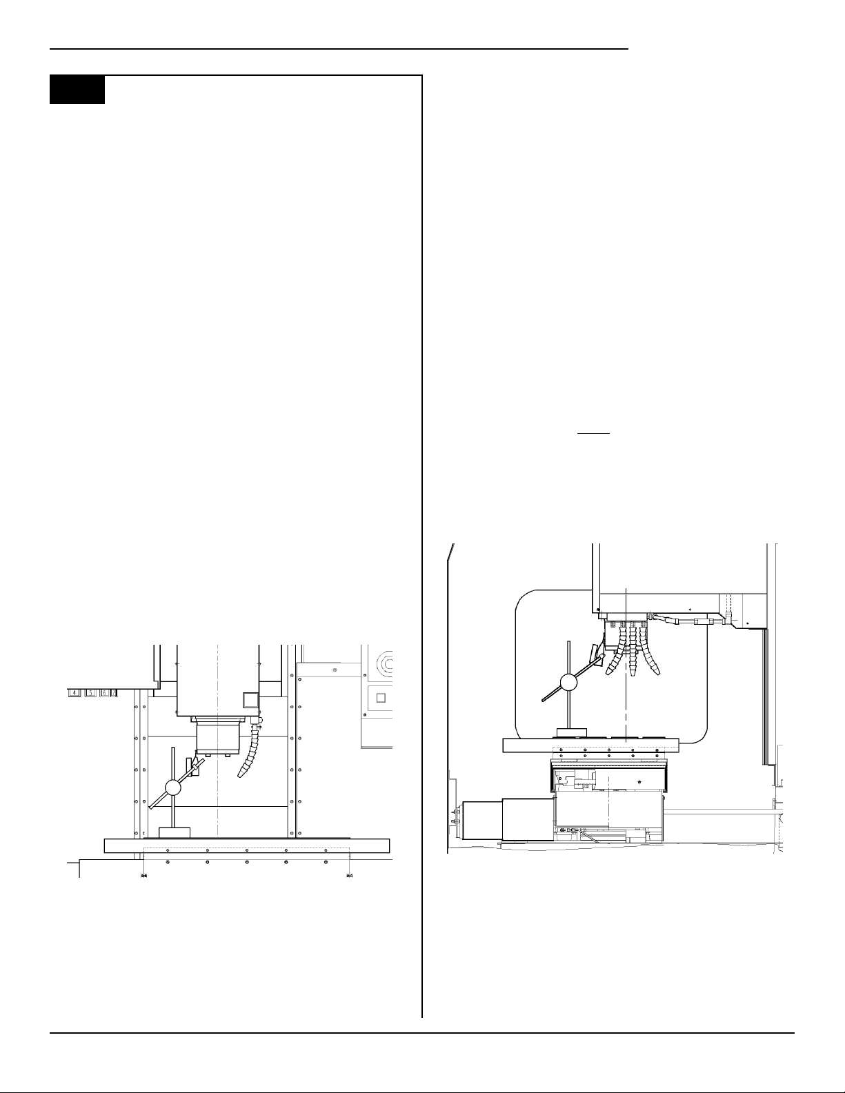
An alternate method for checking backlash
is to place the dial indicator as shown in Fig. 3-1
and manually push on the mill table in both
directions. The dial indicator should return to
zero after releasing the table.
NOTE: The servos must be on to check backlash by this method.
CHECKING Y-AXIS:
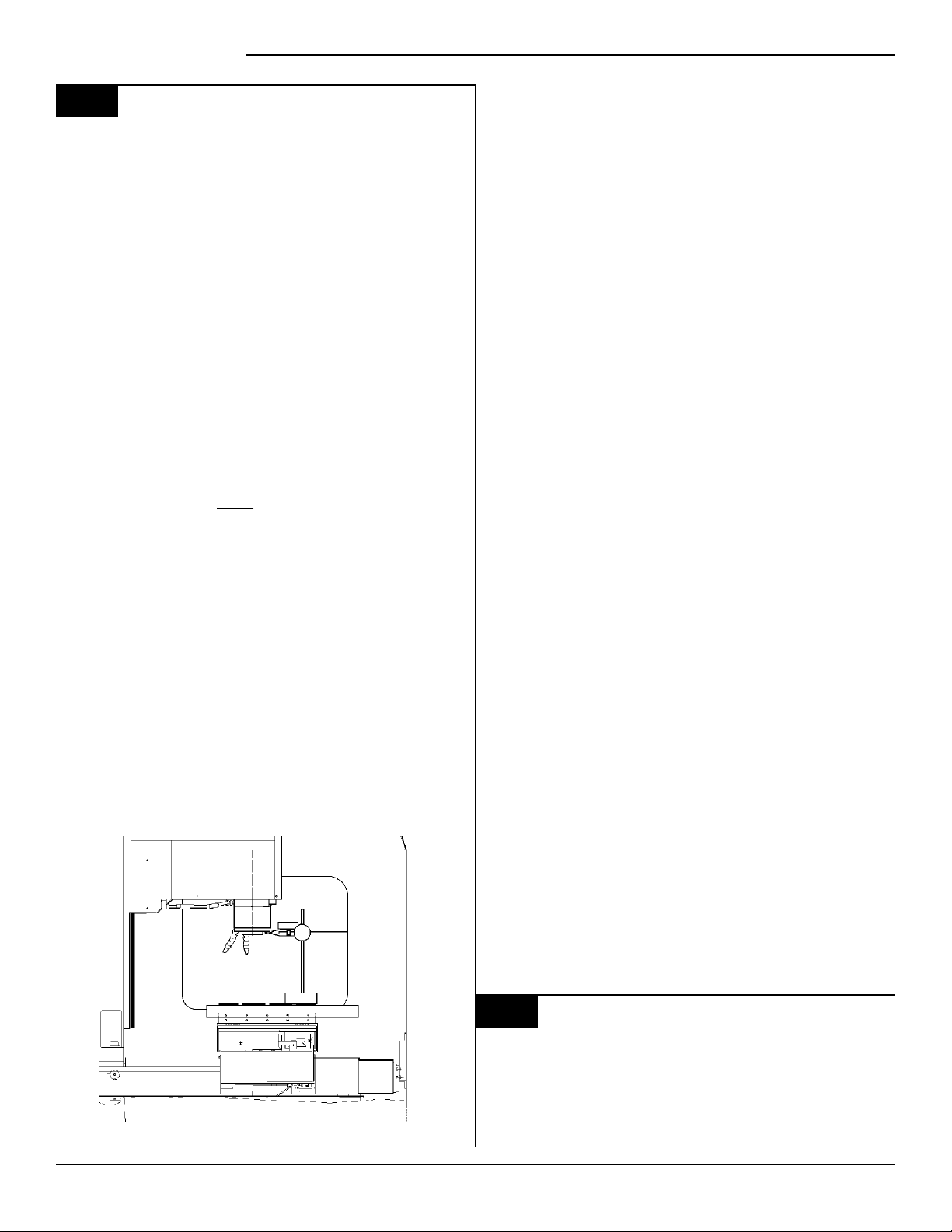
1. Set up a dial indicator and base on the mill
table as shown in Fig. 3-2.
CHECKING X-AXIS:
1. Set up a dial indicator and base on the mill
table as shown in Fig. 3-1.
Fig. 3-1 Dial indicator in position to check X-axis.
2. Set dial indicator and the "Distance to go"
display in the HANDLE JOG mode to zero as
follows:
- Zero the dial indicator.
- Press the MDI button on the control panel.
- Press the HANDLE JOG button on the
Fig. 3-2 Dial indicator in position to check Y-axis.
2. Set dial indicator and the "Distance to go"
display in the HANDLE JOG mode to zero as
follows:
- Zero the dial indicator.
- Press the MDI button on the control panel.
- Press the HANDLE JOG button on the
(Cont'd)
HAAS AUTOMATION, INC. 96-7045 VF SERIES SERVICE MANUAL
13
Page 15
VF Series Service Manual
3.3
3. Set the rate of travel to .001 on the control
panel and jog the machine .010 in the positive
(+) Y direction. Jog back to zero (0) on the display.
The dial indicator should read zero (0) ± .0001.
4. Repeat step three in the negative (-) direction.
TOTAL DEVIATION BETWEEN THE DIAL INDICATOR AND THE CONTROL PANEL DISPLAY
SHOULD NOT EXCEED .0002.
is to place the dial indicator as shown in Fig. 3-2
and manually push on the mill table in both
directions. The dial indicator should return to
zero after releasing the table.
NOTE: The servos must be on to check backlash by this method.
(Cont'd)
control panel. The "Distance to go" display
on the lower right hand corner should read:
X=0 Y=0 Z=0
An alternate method for checking backlash
> If backlash is found in the system,
check for the following possible causes:
· Loose SHCS attaching the ball nut to the nut
housing. Tighten the SHCS as described
in Section 11, Mechanical Service.
· Loose SHCS attaching the nut housing to
the mill table, spindle head, or saddle,
depending on the axis. Tighten the SHCS
as described in Section 11, Mechanical
Service.
· Loose clamp nut on the bearing sleeve.
Tighten the SHCS on the clamp nut.
· Loose motor coupling. Tighten as described
in Section 10.4, Mechanical Service.
· Broken or loose flex plates on the motor
coupling.
(NOTE: The coupling cannot be serviced
in the field and must be replaced as a
unit if it is found to be defective. See
Section 10.4, Mechanical Service.)
CHECKING Z-AXIS:
1. Set up a dial indicator and base on the mill
table as shown in Fig. 3-3.
2. Manually push up and down on the spindle
head while listening for a 'clunk'. Also, watch for
any rapid change in the dial indicator. Either of
these indicate possible backlash.
NOTE: Servos must be on to check for backlash
in the Z-axis.
NOTE: Do not mistake deflection for backlash in
the system.
· Loose SHCS attaching the bearing sleeve
to the motor housing. Tighten as described
in Section 12, Mechanical Service.
· Defective thrust bearings in the bearing
sleeve. Replace the bearing sleeve as
outlined in Section 12, Mechanical Service.
· Loose SHCS attaching the axis motor to
the motor housing. If the SHCS are
found to be loose, inspect the motor for
damage and if none is found, tighten as
described in Section 10, Mechanical
Service. If damage is found, replace the
motor (Section 10, Mechanical Service.)
· Incorrect backlash compensation number
in the parameter in the machine. Check
Parameters 13, 27, and 41.
· Worn lead screw. Replace as outlined in
Section 11, Mechanical Service.
3.4
PROBLEM:
? Excessive servo motor vibration.
Fig. 3-3 Dial indicator in position to check Z-axis.
VF SERIES SERVICE MANUAL 96-7045 Publication Date: November 26, 1993
14
VIBRATION
Page 16

VF Series Service Manual
SOLUTION:
· If no "A" axis is present, swap the
suspected bad servo motor with the "A"
driver and check to see if there is a driver
problem. If needed, replace the DRIVER
PCB (Section 4.2, Electrical Service).
· Check all Parameters of the suspected
axis against the Parameters as shipped
with the machine. If there are any
differences, correct those and determine
how the Parameters were changed.
PARAMETER LOCK should normally be on.
· A bad motor can cause vibration if there is
an open or short in the motor. A short
would normally cause a GROUND FAULT
or OVERCURRENT alarm; check the
ALARMS. An ohmmeter applied to the
motor leads should show between 1 and 3
ohms between leads, and over 1
megohm from leads to chassis. If the
motor is open or shorted, replace (Section
10, Mechanical Service).
SOLUTION:
· Check DC bus voltage on diagnostics
page #2. If it is at the low side of the
recommended voltages, change the
transformer tap to the next lower voltage
group as explained in the Installation
Manual.
· Check motor wiring.
· Replace driver card (Section 4.2, Electrical
Service).
· Replace servo motor (Section 10, Mechanical
Service).
3.5
PROBLEM:
? Servo motor overheating.
SOLUTION:
3.6
OVERHEATING
· If a motor OVERHEAT alarm occurs
(ALARMS 135-138), check the Parameters
for an incorrect setting. Axis flags in
Parameters 1, 15, or 29 can invert the
overheat switch (OVER TEMP NC).
· If the motor is actually getting hot to the
touch, there is excessive load on the
motor. Check the user's application for
excessive load or high duty cycle. Check
the lead screw for binding (Section 3.3). If
the motor is binding by itself, replace
(Section 10, Mechanical Service).
FOLLOWING ERROR
PROBLEM:
? Following error alarms occur on one or
more axes sporadically.
HAAS AUTOMATION, INC. 96-7045 VF SERIES SERVICE MANUAL
15
Page 17

VF Series Service Manual
VF SERIES SERVICE MANUAL 96-7045 Publication Date: November 26, 1993
16
Page 18

VF Series Service Manual
4. Automatic Tool Changer
Before any of the following checks are made, you must first ensure the spindle orientation, drawbar
height, and the tool clamp/unclamp switch adjustments are correct. Refer to Section 6, Mechanical
Service, before proceeding.
4.1
aged drawbar. Before beginning any troubleshooting, observe the direction of the ATC
deflection.
PROBLEM:
? During a tool change, ATC appears to be
SOLUTION:
DEFLECTION
Deflection is usually caused by ATC
misalignment, and sometimes caused
i
pushed down.
· Check to see if pull studs on the tool
· Check the adjustment of the "Z" offset
· Check Parameters 71, 72, and 143 against
· Ensure the tool holders are held firmly in
· Ensure the balls on the drawbar move
by damaged or poor quality tooling, a
damaged spindle taper, or a dam-
holder are correct and tight.
(Parameter 64, Section 8, Mechanical
Service). NOTE: If the offset is incorrect,
a tool changer crash has occurred, and a
thorough inspection of the ATC is necessary
at this time.
the values that are in the documentation
sent with the machine.
place by the extractor forks.
freely in the holes in the drawbar when
the tool release button is pressed. If they
do not move freely, the ATC will be
pushed down about ¼" before the tool
holder is seated in the taper, resulting in
damage to the roller bolts on the ATC
shuttle. Replace drawbar (Section 5.3,
Mechanical Service).
out of the spindle taper.
NOTE: This problem may occur after loading
a cold tool into a hot spindle (a result of
thermal expansion of the tool holder inside
the spindle taper), or after heavy milling. If
sticking occurs only during these
circumstances, no service is necessary.
SOLUTION:
· Check the condition of the customer's
tooling, verifying the taper on the tool
holder is ground and not turned. Look for
damage to the taper caused by chips in
the taper or rough handling. If the tooling
is suspected, try to duplicate the symptoms
with different tooling.
· Check the condition of the spindle taper.
Look for damage caused by chips or
damaged tooling. Also, look for damage
such as deep gouges in the spindle taper
caused by tool crashing. See Section 5,
Mechanical Service, for spindle cartridge
replacement.
· Duplicate the cutting conditions under
which the deflection occurs, but do not
execute an automatic tool change. Try
instead to release the tool using the tool
release button on the front of the spindle
head. If sticking is observed, the deflection
is not caused by improper ATC adjustment,
but is a problem in the spindle head on the
machine. See Section 5, Mechanical
Service, for spindle cartridge replacement.
PROBLEM:
? During a tool change, ATC appears to be
pulled up; no popping noises.
SOLUTION:
PROBLEM:
? Tool holder sticking in the spindle taper
causes the ATC to be pulled up as the
spindle head is traveling up after depositing
the tool holder in the carousel; accompanied
by a popping noise as the tool holder pops
HAAS AUTOMATION, INC. 96-7045 VF SERIES SERVICE MANUAL
· Check the adjustment of the "Z" offset
(Parameter 64, Section 8, Mechanical
Service). NOTE: If the offset is incorrect,
a tool changer crash has occurred, and a
thorough inspection of the ATC is necessary
at this time.
(Cont'd)
17
Page 19

VF Series Service Manual
4.1
(Cont'd)
· Ensure the roller bolts on the shuttle of
the ATC are tight against the v-guides on
the ATC holding arm. If the lower right
roller bolt is loose against the v-guide, the
upper right bolt is probably bent. See the
following section (ATC Crashing) or Section
14.2, Mechanical Service, for roller bolt
replacement.
NOTE: Bent roller bolts are a symptom of
another problem with the ATC. Repair the
bent roller bolt and then isolate the ATC
problem.
· Check Parameter 71 against the values
that are in the documentation sent with
the machine.
· Ensure the balls on the drawbar move
freely in the holes in the drawbar when
the tool release button is pressed. If they
do not move freely, the ATC will be
pushed down about ¼" before the tool
holder is seated in the taper, resulting in
damage to the roller bolts on the ATC
shuttle. Replace drawbar (Section 5.3,
Mechanical Service).
SOLUTION:
· Check all the extractor forks to ensure they
are centered in the pocket of the ATC. Also,
see above. See Section 14.6, Mechanical
Service, for extractor fork replacement.
NOTE: If the ATC shows the problem as
described here, each extractor fork must
be checked and centered to eliminate the
possibility of the ATC being aligned against
an incorrectly-centered fork.
4.2
operator error. The most common ATC crashes
are outlined as follows:
PROBLEM:
? Shuttle crashes into spindle when a tool
SOLUTION:
CRASHING
Crashing of the ATC is usually a result of
change is commanded (tool holder is in the
pocket facing the spindle head).
· Rotate the carousel to an empty pocket.
Refer to the Programming and Operation
manual for correct operation.
PROBLEM:
? Tool holders twist against extractor fork
during a tool change.
SOLUTION:
· Check the alignment of the ATC in the X
and Y axes (Section 14.3, Mechanical
Service).
PROBLEM:
? Tool holders spin at all pockets of the ATC
when the ATC shuttle retracts.
SOLUTION:
· ATC is misaligned in the "Y" axis. Realign
ATC (Section 14.3, Mechanical Service).
NOTE: Observe the direction the tool
holder rotates, as this will be the direction
in which the "Y" axis of the ATC needs to
be moved.
PROBLEM:
? Tool holders spin only at certain pockets of
the ATC when the ATC shuttle retracts.
NOTE: This crash is fairly common
i
command the ATC to an empty pocket before
the machine will operate correctly. Repeated
crashes of this type can damage the I/O board,
the slip clutch, and the shuttle motor in the ATC.
PROBLEM:
? Spindle crashes into top of the tool holder
SOLUTION:
· Check all of the extractor forks on the
and is a result of operator error. If
the ATC is stopped in the middle of
tool change cycle, the operator must
after a turret rotation during a tool change.
When the spindle head moves down over
the top of the tool holder during a tool
change, the pull stud will bind inside the
drawbar bore of the spindle, forcing the ATC
down, bending the upper right roller bolt on
the ATC shuttle or completely breaking it off.
Tool holder is not held correctly in the
extractor fork, possibly held only in one side
of the extractor and at an odd angle.
ATC. Replace, if needed (Section 14.6,
Mechanical Service).
VF SERIES SERVICE MANUAL 96-7045 Publication Date: November 26, 1993
18
Page 20

VF Series Service Manual
PROBLEM:
? Spindle crashes into top of the tool holder
after a turret rotation during a tool change.
The balls in the drawbar do not move freely,
causing the ATC to be forced down far
enough to bend the upper right roller bolt or
completely break it off.
SOLUTION:
· Ensure the balls on the drawbar move
freely in the holes in the drawbar when the
tool release button is pressed. If this
failure occurs, check all of the extractor
forks on the ATC for damage and repair the
spindle drawbar. See Section 14.1 for ATC
shuttle replacement, Section 5.3,
Mechanical Service, for drawbar
replacement, and 14.2, Mechanical Service,
for extractor fork replacement.
PROBLEM:
? ATC properly deposits a tool holder in the
spindle, but the tools are dropped onto the
machine table when the shuttle retracts.
SOLUTION:
· Inspect the balls and the Belleville springs
in the drawbar. See Section 5.3, Mechanical
Service, for drawbar replacement.
PROBLEM:
? The part or fixture on the mill table crashes
into long tooling or into the ATC itself during
a tool change.
SOLUTION:
· Program the machine to move the part out
of the way of the ATC. Inspect the pocket
involved in the crash for damage and
replace parts as necessary.
programmed to rotate long tools clear of
the part, the correct carousel position
must be programmed back in before a tool
change can be executed.
NOTE: If these crashes occur, thoroughly
inspect the ATC for damage. Pay close
attention to the extractor forks, the sliding
covers on the ATC carousel, and the roller
bolts on the ATC shuttle. See Section 14.2,
Mechanical Service for extractor fork
replacement and Section 14.7, Mechanical
Service, for sliding door replacement.
4.3
very hard or repeated crashes.
PROBLEM:
? ATC shuttle is broken off of the holding plate.
SOLUTION:
PROBLEM:
? ATC extractor forks are damaged after
SOLUTION:
BREAKAGE
Breakage of the ATC is caused by either
· Carefully inspect the bosses on the shuttle
casting (where the roller bolts mount) for
damage to the threads or cracks. If any of
the bosses are cracked, replace the casting.
Realign the tool changer after repairing
the machine (Section 14, Mechanical
Service).
breakage.
· Check the condition of the mounting holes
in the carousel. If the threads are damaged,
they must be repaired or the carousel
replaced. See Section 14.6, Mechanical
Service, for extractor fork replacement.
PROBLEM:
? The part or fixture on the mill table crashes
into long tooling or into the ATC itself when
machining.
SOLUTION:
· Either reposition the tools to remove the
interference, or program the carousel to
rotate long tooling out of the way of the
part (USE THIS ONLY AS A LAST RESORT).
CAUTION! If the carousel has to be
HAAS AUTOMATION, INC. 96-7045 VF SERIES SERVICE MANUAL
4.4
observe the ATC in operation and look for the
following:
PROBLEM:
? ATC makes noise as the shuttle moves.
NOISY OPERATION
To isolate noise(s) in the ATC, carefully
(Cont'd)
19
Page 21

VF Series Service Manual
4.4
SOLUTION:
PROBLEM:
? ATC makes noise during carousel rotation.
SOLUTION:
(Cont'd)
· Check the adjustment of the roller bolts on
the ATC (Section 14.2, Mechanical Service).
Loose roller bolts can cause the ATC to
make a clunking noise when the shuttle is
commanded to move. Tight roller bolts
can cause the shuttle motor to labor
excessively, possibly damaging the motor
or the I/O board. In this case, the shuttle
may also move too slowly.
· Check for damage to the trap door on the
ATC cover. See Section 14.11, Mechanical
Service, for trap door replacement.
· Check for missing plastic riders on the
ATC shutter. See Section 14.11, Mechanical
Service, for shutter replacement.
· Ensure the guide pin mounted to the
holding plate is not bent and does not
scrape the ATC cover during movement.
See Section 14.11, Mechanical service,
for guide pin replacement.
· Listen for damage to the gear train in the
shuttle motor. If the motor is found to be
the source of the noise, replace the motor
(Section 14.8, Mechanical Service). DO
NOT try to repair the motor or to further
isolate the noise in the motor.
· Check to ensure the Geneva driver on the
turret motor is tight and properly adjusted
(Section 14.8, Mechanical Service). If the
Geneva driver is found to be loose, check
for damage to the Geneva star. Any
roughness in the slots will require that it
be replaced (Section 14.10, Mechanical
Service).
· Check the adjustment of the Geneva driver
in relation to the Geneva star (Section 14.10,
Mechanical Service). If the adjustment is
too loose, the carousel will vibrate heavily
and make a loud clanking noise during
carousel rotation. If the adjustment is too
tight, the turret motor will labor excessively
and the carousel may appear to move
erratically. NOTE: If the turret motor
adjustment is tight for extended periods,
the turret motor, Geneva star, and the I/O
board may be damaged. If the adjustment
of the Geneva star appears tight at some
pockets and loose at others, the problem
lies with the Geneva star. Check the
concentricity of the star relative to the
bearing housing on the carousel assembly.
If the concentricity of the star is proven to
within specification and the problem still
persists, the Geneva star must be replaced
(Section 14.10, Mechanical Service).
· Ensure the screws holding the turret
motor to the mounting plate are tight
(Section 14.9, Mechanical Service).
· Ensure the screws attaching the motor
mounting plate to the shuttle casting are
tight.
· Check for excessive noise in the gear train
of the turret motor. See Section 14.9,
Mechanical Service, for turret motor
replacement.
NOTE: If the motor is found to be the
source of noise, replace the motor assembly
(motor, mounting plate, and Geneva driver).
DO NOT attempt to repair the motor or to
further isolate the problem in the motor.
4.5
SPINDLE ORIENTATION
A switch is used to sense when the pin drops
in to lock the spindle. When the pin drops the
switch opens, indicating orientation is complete.
The normally-closed side of this switch is wired
to the spindle drive and commands it into the
COAST STOP condition. This is done to make
sure that the spindle motor is not powered when
the pin is locking the spindle.
If, during a tool change, the dogs on the spindle
shaft do not align with the keys on the ATC
carousel, the spindle orientation may be at fault.
The orientation of the spindle is as follows:
1) If the spindle is turning, it is commanded
to stop,
2) Pause until spindle is stopped,
3) Spindle orientation speed is commanded
forward,
4) Pause until spindle is at orientation
speed,
5) Command spindle lock air solenoid active,
6) Pause until spindle locked status is
active and stable,
VF SERIES SERVICE MANUAL 96-7045 Publication Date: November 26, 1993
20
Page 22

VF Series Service Manual
7) If not locked after time-out time, alarm
and stop.
PROBLEM:
? ATC out of orientation with the spindle.
Incorrect spindle orientation will cause the
ATC to crash as the shuttle moves. Alarm
113 will be generated.
SOLUTION:
· Check the orientation of the machine
(Section 7, Mechanical Service).
4.6
run, an alarm is generated to indicate either a
shuttle in/out problem or a turret rotation problem.
These alarms will occur either on an attempt to
change tools (ATC FWD) or ZERO RETURN the
machine (AUTO ALL AXES). Use the appropriate alarm to select one of the problems following:
ATC WILL NOT RUN
In all cases where the tool changer will not
PROBLEM:
? ATC shuttle will not move; shuttle is not
getting power (Command a tool change and
feel for power being applied to the shuttle
motor).
SOLUTION:
· Check that the TC IN/TC OUT LED on the
I/O PCB is illuminated when a tool change
takes place.
> If the LED lights, check the fuse FU5
on the POWER PCB. Otherwise, replace
the I/O PCB (Section 4.3, Electrical Service).
> If the LED does not light, check cables
510 and 520.
PROBLEM:
? ATC turret will not rotate; turret motor is
getting power (command a tool change and
feel for power being applied to the turret
motor).
SOLUTION:
PROBLEM:
? ATC shuttle will not move; shuttle is getting
power (Command a tool change and feel for
power being applied to the shuttle motor).
SOLUTION:
· Disconnect the slip clutch arm from the
ATC shuttle and ensure the shuttle can
move freely. If not, see Sections 14.1,
14.3, and 14.4, Mechanical Service, for
shuttle adjustment.
· Command a tool change with the shuttle
disconnected.
> If the shuttle cycles, check the slip clutch
on the ATC. See Section 14.8, Mechanical
Service, for slip clutch replacement.
NOTE: The slip clutch should move the
shuttle with a fair amount of force, but not
so much that the shuttle cannot be made
to slip when holding it back by hand. If
the slip clutch is frozen, replace it. It
cannot be rebuilt in the field.
> If the shuttle does not cycle, the motor
has failed and must be replaced. Turn the
motor by hand and feel for binding in the
gear train in the motor. See Section 14.8,
Mechanical Service.
NOTE: The motor uses a large amount of
gear reduction and should be hard to turn
by hand.
· If power is applied but the output shaft
on the motor does not turn, check for
binding between the turret motor assembly
and the Geneva star (Section 14.9, Mechanical
Service). Check for damage to the Geneva
star or the Geneva driver. See Section
14.10, Mechanical Service, for Geneva
star replacement, and 14.9 for turret
motor replacement. Check for a broken
turret motor (See Section 14.9, Mechanical
Service for turret motor replacement).
NOTE: Do not attempt to repair the motor
or to further isolate the problem in the
motor.
PROBLEM:
? ATC turret will not rotate; turret motor is
not getting power (command a tool change
and feel for power being applied to the
turret motor).
SOLUTION:
· Check that the TC CW/ TC CCW LED on
the I/O PCB is illuminated when a tool
change takes place.
> If the LED lights, check the fuse FU5
on the POWER PCB. Otherwise, replace
the I/O PCB (Section 4.3, Electrical Service).
> If the LED does not light, check cables
510 and 520.
HAAS AUTOMATION, INC. 96-7045 VF SERIES SERVICE MANUAL
21
Page 23

VF Series Service Manual
VF SERIES SERVICE MANUAL 96-7045 Publication Date: November 26, 1993
22
Page 24

VF Series Service Manual
5. Gearbox and Spindle Motor
The gearbox cannot be serviced in the field and must be replaced as a unit. NEVER remove a
motor from a VF-1, VF-2, or VF-3 gearbox as this will damage the gearbox and void the warranty.
5.1
noise, also refer to Section 2 (Spindle Troubleshooting). Gearboxes can be damaged by
failed air solenoids, gearshift cylinders, or
bearings, resulting in noisy operation. It is not
likely that poor finish on a workpiece can be
attributed to a bad gearbox.
PROBLEM:
? Excessive or unusual noise coming from the
SOLUTION:
NOISE
When investigating complaints of gearbox
gearbox and/or spindle motor.
· Operate the machine in both high and low
gears. Monitor the gearbox for noise in
both gear positions and if the pitch of the
noise varies with the motor or the output
shaft speed.
> If the noise only occurs in one gear
throughout the entire RPM range of that
gear position, the problem lies with the
gearbox, and it must be replaced (Section
9, Mechanical Service).
> If the noise occurs in both gear positions,
disconnect the drive belt and repeat the
previous step. If the noise persists, the
gearbox is damaged and must be replaced
(Section 9, Mechanical Service).
> With the drive belt disconnected, run
the machine at 1000 RPM in high gear.
Command a change of direction and listen
for a banging noise in the gearbox as the
machine slows to zero RPM and speeds
back up to 1000 RPM in reverse. If the
noise occurs, the motor has failed and the
gearbox must be replaced (Section 9,
Mechanical Service).
NOTE: Whenever a gear change problem
occurs, an alarm will also occur. Refer to
the ALARMS section (Section 6) to diagnose
each problem before working on the
machine.
When a gear change is performed, the
following sequence of events occurs:
1) If the spindle is turning, it is commanded
to stop,
2) Pause until spindle is stopped,
3) Gear change spindle speed is
commanded forward,
4) Pause until spindle is at speed,
5) Command high or low gear solenoid
active,
6) Pause until in new gear or reversal time,
7) Alarm and stop if max gear change time
elapsed,
8) If not in new gear, reverse spindle
direction, go 8,
9) Turn off high and low gear solenoids.
SOLUTION:
· Check the air solenoid assembly on the
solenoid bracket (rear of gearbox). If the
solenoid operates properly and the limit
switches on the gearbox operate properly,
the problem lies with the gear change
piston. Replace the gearbox (Section 9,
Mechanical Service).
· Check contactor CB4.
5.3
PROBLEM:
? Alarm 179 (Low Pressure Spindle Coolant)
CORRECTING ALARMS
has been triggered.
5.2
PROBLEM:
? Machine will not execute a gear change.
HAAS AUTOMATION, INC. 96-7045 VF SERIES SERVICE MANUAL
GEARS WILL NOT CHANGE
SOLUTION:
· Check for low oil supply in reservoir.
· Check to see that pump motor is running.
(Cont'd)
23
Page 25

VF Series Service Manual
5.3
· Check for an air leak in the suction side of
· Check for a bad pressure sensor.
· Check for a broken or damaged cable.
· Check for a worn pump head.
(Cont'd)
the pump.
VF SERIES SERVICE MANUAL 96-7045 Publication Date: November 26, 1993
24
Page 26

VF Series Service Manual
6. Alarms / Diagnostics
Any time an alarm is present, the lower right hand corner will have a blinking "ALARM." Push the
ALARM display key to view the current alarm. All alarms are displayed with a reference number and a
complete description. If the RESET key is pressed, one alarm will be removed from the list of alarms. If
there are more than 18 alarms, only the last 18 will be displayed and the CURSOR DOWN key must be
used to see the rest. The presence of any alarm will prevent the operator from starting a program.
Note that the tool changer alarms can be easily corrected by first correcting any mechanical problem,
pressing RESET until the alarms are clear, selecting ZERO RET mode, and selecting AUTO ALL AXES.
Some messages are displayed while editing to tell the operator what is wrong, but these are not alarms.
The following list shows the alarm number and the cause of the alarm. Please refer to this list
before resuming normal operation when an alarm occurs.
102 SERVOS OFF
This is not an alarm; but indicates that the servo motors are off, the tool changer is disabled, the coolant pump is off, and the spindle motor is stopped. Caused by EMERGENCY
STOP, motor faults, tool changer problems, or power fail.; check for other causes.
103 X FOLLOWING ERROR TOO LARGE
104 Y FOLLOWING ERROR TOO LARGE
105 Z FOLLOWING ERROR TOO LARGE
106 A FOLLOWING ERROR TOO LARGE
These alarms can be caused by power problems, motor problems, driver problems, the
slide being run into the mechanical stops, or excessive axis load. The difference between
the motor position and the commanded position has exceeded a parameter. The motor
may also be stalled, disconnected, or the driver failed. The servos will be turned off and a
RESET must be done to restart. See Section 2, Electrical Service, to check line voltage
adjustments. See Section 3.1, Electrical Service, check the servo motors, servo drivers,
and ball screw adjustment.
107 EMERGENCY OFF
EMERGENCY STOP button was pressed. Servos are also turned off. After the E-STOP is
released, the RESET button must be pressed at least twice to correct this; once to clear
the E-STOP alarm and once to clear the Servo Off alarm. This is an operator-initiated
condition. If you do not know why it occurred, check wiring to emergency stop circuit.
108 X SERVO OVERLOAD
109 Y SERVO OVERLOAD
110 Z SERVO OVERLOAD
111 A SERVO OVERLOAD
Excessive load on X-axis motor. This can occur if the load on the motor over a period of
several seconds or even minutes is large enough to exceed the continuous rating of the
motor. The servos will be turned off when this occurs. This can be caused by running into
the mechanical stops but not much past them. It can also be caused by anything that
causes a very high load on the motors. See Section 3.1, Electrical Service, to check the
servo motors, servo drivers, and ball screw adjustment.
112 NO INTERRUPT
This alarm can be caused by electrical interference or an electronics problem. See
Section 4.1, Electrical Service, to replace Microprocessor and Motor Interface PCB's.
(Cont'd)
HAAS AUTOMATION, INC. 96-7045 VF SERIES SERVICE MANUAL
25
Page 27

VF Series Service Manual
6.
113 SHUTTLE IN FAULT
114 SHUTTLE OUT FAULT
115 TURRET ROTATE FAULT
116 SPINDLE ORIENTATION FAULT
(Cont'd)
Tool changer not completely to right or left. During a tool changer operation the tool in/out
shuttle failed to get to the in or out position. Parameters 62 and 63 can adjust the timeout times. This alarm can be caused by anything that jams the motion of the slide or by the
presence of a tool in the pocket facing the spindle. A loss of power to the tool changer
can also cause this, so check fuse FU5 and relays 1-8, 2-1, and 2-2. See Section 4 for
troubleshooting of the tool changer.
Tool carousel motor not in position. During a tool changer operation the tool turret failed to
start moving or failed to stop at the right position. Parameters 60 and 61 can adjust the
time-out times. This alarm can be caused by anything that jams the rotation of the turret. A
loss of power to the tool changer can also cause this, so check fuse FU5 and relays 1-8,
2-3, and 2-4. See Section 4 for troubleshooting of the tool changer.
Spindle did not orient correctly. During a spindle orientation function, the spindle is
rotated until the lock pin drops in; but the lock pin never dropped. Parameters 66, 70, 73,
and 74 can adjust the time-out times. This can be caused by a trip of circuit breaker CB4,
a lack of air pressure, or too much friction with the orientation pin. See Section 4.5 to
troubleshoot spindle orientation.
117 SPINDLE HIGH GEAR FAULT
118 SPINDLE LOW GEAR FAULT
Gearbox did not shift into high or low gear. During a gear change, the spindle is rotated
slowly while air pressure is used to move the gears but the high/low gear sensor was not
detected in time. Parameters 67, 70 and 75 can adjust the time-out times. Check the air
pressure, the solenoids circuit breaker CB4, and the spindle drive. See Section 5 for
troubleshooting of gear change problems.
119 OVER VOLTAGE
Incoming line voltage is above maximum (about 255V when wired for 240 or 235 when
wired for 208). The servos will be turned off and the spindle, tool changer, and coolant
pump will stop. If this condition remains for 4.5 minutes, an automatic shutdown will
begin. This can also be caused by an electronic problem. See Section 2, Electrical
Service, to check line voltage adjustment taps. See Section 4.2, Electrical Service, to
replace SDIST PCB. Also check that servo regen load resistor is installed (cable 920).
120 LOW AIR PRESSURE
Air pressure dropped below 80 PSI for a period defined by Parameter 76. Check your
incoming air pressure for at least 100 PSI and ensure the regulator is set at 85 PSI. If this
is not caused by low air pressure, check pressure sensor at spindle head and wiring back
to IOPCB. Check Parameter 76, which is used to delay the low air alarm condition for
short outages. Air blast during tool change can cause your air supply to drop pressure;
monitor the pressure drop during a tool unclamp.
121 LOW LUB OR LOW PRESSURE
Way lube is low or empty or there is no lube pressure or too high a pressure. Check tank at
rear of mill and below control cabinet. Also check connector P5 on the side of the control
cabinet. Check that the lube lines are not blocked. This can be caused by failure of the
pump to provide pressure, failure of the lube pressure sensor, a wiring error, or a parameter error. See Air and Oil Line Diagrams (p.133) to check level switch and pressure
switch (cable 960).
VF SERIES SERVICE MANUAL 96-7045 Publication Date: November 26, 1993
26
Page 28

122 CONTROL OVER HEAT
The control internal temperature is above 150° F. This can be caused by almost anything
in the control overheating. But is usually caused by overheat of the two regen resistors for
servos and spindle drive. This alarm will also turn off the servos, spindle drive, coolant
pump, and tool changer. One common cause of this overheat condition is an input line
voltage too high. If this condition remains for 4.5 minutes, an automatic shutdown will
begin. It is also caused by incorrect transformer tapping, SDIST PCB problem, or Spindle
Drive problem. See Section 2, Electrical Service, to check line voltage adjustment taps.
See Section 4.2, Electrical Service, to replace SDIST PCB. See Section 2.3 to check the
spindle drive.
123 SPINDLE DRIVE FAULT
Overheat or failure of spindle drive or motor. The exact cause is indicated in the LED
window of the spindle drive inside the control cabinet. This can be caused by a stalled
motor, shorted motor, overvoltage, undervoltage, overcurrent, overheat of motor, or drive
failure. See Section 2.3 for check of the Spindle Drive. Front of Drive indicates type of
problem. If not a Drive problem, check wiring to IOPCB (cable 780).
124 LOW BATTERY
Memory batteries need replacing within 30 days. This alarm is only generated at POWER
ON and indicates that the 3.3V Lithium battery is below 2.5V. If this is not corrected within
about 30 days, stored programs, parameters, offsets, and settings may be lost. See
Section 4.1, Electrical Service, for replacement of Microprocessor PCB or battery.
VF Series Service Manual
125 SHUTTLE FAULT
Tool shuttle not initialized at power on, CYCLE START or spindle motion command. This
means that the tool shuttle was not fully retracted to the out position. See Section 4 for
tool changer problem.
126 GEAR FAULT
Gearshifter is out of position when a command is given to rotate the spindle. This means
that the two-speed gear box is not in either high or low gear but is somewhere in between.
Check the air pressure, the solenoids circuit breaker CB4, and the spindle drive. See
Section 5 for gear change problem.
127 NO TURRET MARK
Tool carousel motor not in position. The turret motor only stops in one position indicated
by a switch and cam on the Geneva mechanism. This alarm is only generated at POWER
ON. The AUTO ALL AXES button will correct this but be sure that the pocket facing the
spindle afterwards does not contain a tool. See Section 4 for tool changer problem.
128 TOOL IN TURRET
Pocket opposite spindle has tool in it. This alarm is not implemented.
129 M FIN FAULT
This indicates an external M-code wiring error was detected at power-on. Check your
wiring to the M-FIN signal or see Section 4.3, Electrical Service, for replacement of the
IOPCB.
130 TOOL UNCLAMPED
131 TOOL NOT CLAMPED
Tool release piston is energized at power up, or, tool release piston is not Home. This is a
possible fault in the air solenoids, relays on the IO Assembly, the draw bar assembly, or
wiring. See Sections 2.6 and 4.1 for tool clamp/unclamp problems.
(Cont'd)
HAAS AUTOMATION, INC. 96-7045 VF SERIES SERVICE MANUAL
27
Page 29

VF Series Service Manual
6.
132 POWER DOWN FAILURE
133 SPINDLE LOCKED
134 TOOL CLAMP FAULT
135 X MOTOR OVER HEAT
136 Y MOTOR OVER HEAT
137 Z MOTOR OVER HEAT
138 A MOTOR OVER HEAT
(Cont'd)
The control attempted to shut-off and could not. The auto-off relay on the IOPCB did not
open the main contactor circuit. Check the wiring from IOPCB to POWER PCB. See
Section 4.3, Electrical Service, for IOPCB replacement.
Shot pin did not release. This is detected when spindle motion is commanded. Check the
solenoid that controls the air to the lock, relay 2-8, the wiring to the sense switch, and the
switch. See Section 2.5 for spindle orientation checks. Check for correct function of the
shot pin.
Tool did not release from spindle when commanded. Check air pressure and solenoid
circuit breaker CB4. Can also be caused by misadjustment of draw bar assembly. See
Sections 2.6 and 4.1 for tool clamp/unclamp problems.
Servo motor overheat. The temperature sensor in the motor indicates over 150°F. This can
be caused by an extended overload of the motor such as leaving the slide at the stops for
several minutes. See Section 3 for check of servo motors and ball screws. A parameter or
a wiring error can also cause this alarm.
139 X MOTOR Z FAULT
140 Y MOTOR Z FAULT
141 Z MOTOR Z FAULT
142 A MOTOR Z FAULT
Encoder marker pulse count failure. This alarm usually indicates that the encoder has
been damaged and encoder position data is unreliable. This can also be caused by loose
connectors at P1-P4. See Section 3.1 for check of motor/encoder and wiring. This is
usually an encoder or wiring error. It can also be caused by the MOTIF PCB. See Section
4.1, Electrical Service, for replacement of MOTIF PCB.
143 SPINDLE NOT LOCKED
Shot pin not fully engaged when a tool change operation is being performed. Check air
pressure and solenoid circuit breaker CB4. This can also be caused by a fault in the
sense switch that detects the position of the lock pin. See Section 2.5 for spindle orientation checks.
144 TIMEOUT - CALL YOUR DEALER
Time allocated for use prior to payment exceeded. Not a mechanical or electrical problem.
145 X LIMIT SWITCH
146 Y LIMIT SWITCH
147 Z LIMIT SWITCH
148 A LIMIT SWITCH
Axis hit limit switch or switch disconnected. This is not normally possible as the stored
stroke limits will stop the slides before they hit the limit switches. Check the wiring to the
limit switches and connector P5 at the side of the main cabinet. Can also be caused by a
loose encoder shaft at the back of the motor or coupling of motor to the screw. See Section 7, Electrical Service, to replace limit switches.
VF SERIES SERVICE MANUAL 96-7045 Publication Date: November 26, 1993
28
Page 30

149 SPINDLE TURNING
Spindle not at zero speed for tool change. A signal from the spindle drive indicating that
the spindle drive is stopped is not present while a tool change operation is going on. See
Section 4.3, Electrical Service, for IOPCB replacement or Section 2 for Spindle Drive
problem.
150 Z AND TOOL INTERLOCKED
Tool changer not at home and Z is neither at machine home or above tool. If RESET, E-STOP,
or POWER OFF occurs during tool change, Z-axis motion and tool changer motion may not
be safe. Check the position of the tool changer and remove the tool if possible. Re-initialize
with the AUTO ALL AXES button but be sure that the pocket facing the spindle afterwards
does not contain a tool. Indicates a dangerous condition with the position of the Z axis
and the tool changer. It is usually preceded by an alarm related to the tool changer. See
Section 4 for troubleshooting of tool changer.
151 LOW COOLANT
If the low coolant sensor is installed, this indicates low coolant level in the coolant tank
outside of the enclosure. Check coolant level and sensor in tank.
152 SELF TEST FAIL
This can be caused by an electronics problem or electrical interference. All motors and
solenoids are shut down. This is most likely caused by a fault of the processor board
stack at the top left of the control. Call your dealer. See Section 4.1, Electrical Service,
for replacement of MOTIF PCB.
VF Series Service Manual
153 X AXIS Z CH MISSING
154 Y AXIS Z CH MISSING
155 Z AXIS Z CH MISSING
156 A AXIS Z CH MISSING
These alarms indicate a problem with the servo axis encoder. All servos are turned off. It
can also be caused by wiring errors, electronics problems, encoder contamination, parameter errors, or by loose connectors at P1-P4.. See Section 9, Mechanical Service, for
replacement of motor/encoder. See Section 4.1, Electrical Service, for replacement of
MOTIF PCB.
157 MOTOR INTERFACE PCB FAILURE
Internal circuit board problem. The MOTIF PCB in the processor stack is tested at POWER
ON. See Section 4.1, Electrical Service, for replacement of MOTIF PCB.
158 VIDEO/KEYBOARD PCB FAILURE
Internal circuit board problem. The VIDEO PCB in the processor stack is tested at POWER
ON. This could also be caused by a short in the front panel membrane keypad. See Section 5.5, Electrical Service, for replacement of keypad. See Section 4.1, Electrical Service, for replacement of VIDEO PCB.
159 KEYBOARD FAILURE
Keyboard shorted or button pressed at POWER ON. A POWER ON test of the membrane
keypad has found a shorted button. It can also be caused by a short in the cable from the
main cabinet or by holding a switch down during POWER ON. See Section 5.5, Electrical
Service, for replacement of keypad. This can also be caused by a bad cable 700. Be
sure the problem is not in the cable before replacing keypad.
160 LOW VOLTAGE
This can be caused by a line voltage problem, a transformer tap problem, or an electronic
problem. Cable 980 can cause this problem. See Section 4.1, Electrical Service, to
replace MOTIF PCB or SDIST PCB.
(Cont'd)
HAAS AUTOMATION, INC. 96-7045 VF SERIES SERVICE MANUAL
29
Page 31

VF Series Service Manual
6.
161 X AXIS OVER CURRENT OR DRIVE FAULT
162 Y AXIS OVER CURRENT OR DRIVE FAULT
163 Z AXIS OVER CURRENT OR DRIVE FAULT
164 A AXIS OVER CURRENT OR DRIVE FAULT
165 X ZERO RET MARGIN TOO SMALL
166 Y ZERO RET MARGIN TOO SMALL
167 Z ZERO RET MARGIN TOO SMALL
168 A ZERO RET MARGIN TOO SMALL
(Cont'd)
These alarms indicate a problem with servo motor, the servo drive, or excessive load on
servos. Possibly caused by a stalled or overloaded motor. The servos are turned off. This
can be caused by running a short distance into a mechanical stop. It can also be caused
by a short in the motor or a short of one motor lead to ground. See Section 4.1, Electrical
Service, for replacement of servo drive cards. See Section 3 for check of servo motor and
ball screw.
This alarm indicates a problem with limit switches, parameters, or motor encoders for
servos, and this alarm will occur if the home/limit switches move or are misadjusted. This
alarm also indicates that the zero return position may not be consistent from one zero
return to the next. The encoder Z channel signal must occur between 1/8 and 7/8 revolution of where the home switch releases. This will not turn the servos off but will stop the
zero return operation. See Section 16, Mechanical Service, for setting grid offset parameters. See Section 3 for checking of motor and encoder. If a new motor or encoder is
installed, this alarm is likely before grid offset parameters are adjusted.
169 SPINDLE DIRECTION FAULT
The spindle started turning in the wrong direction. This alarm occurs only for rigid tapping.
It can be caused by a bad rigid tapping encoder, a wiring error, or a parameter error.
See Section 6, Electrical Service, for installation of rigid tapping encoder.
170 PHASE LOSS L1-L2
171 PHASE LOSS L2-L3
172 PHASE LOSS L3-L1
These alarms indicate a problem with incoming line voltage. This usually indicates that
there was a transient loss of input power to the machine. See Section 2, Electrical Service,
for checking line voltage.
173 SPINDLE REF SIGNAL MISSING
The Z channel pulse from the spindle encoder is missing for hard tapping synchronization.
This alarm occurs only for rigid tapping. See Section 6, Electrical Service, for installation/
check of rigid tapping encoder.
174 TOOL LOAD EXCEEDED
The tool load monitor option is selected and the maximum load for a tool was exceeded in
a feed. This alarm can only occur if the tool load monitor function is installed in your
machine. This is not normally a machine fault. Check the setup.
175 GROUND FAULT DETECTED
A ground fault condition was detected in the 115V AC supply. This can be caused by a
short to ground in any of the servo motors, the tool change motors, the fans, or the oil
pump. If the fault occurs repeatedly, remove motors one at a time to isolate fault. If it
occurs rarely, the motor in motion at the fault is the likely cause. A short of the spindle
head solenoid cables can also cause this condition. See Section 9, Mechanical Service,
to replace servo motors. See Section 14, Mechanical Service, to replace tool changer
motors.
VF SERIES SERVICE MANUAL 96-7045 Publication Date: November 26, 1993
30
Page 32

176 OVER HEAT SHUTDOWN
This alarm is actually caused by a previous Over Heat alarm. After 4 1/2 minutes of
overheat, the control begins an automatic shutdown.
177 OVER VOLTAGE SHUTDOWN
This alarm is actually caused by a previous Over Voltage alarm. After 4 1/2 minutes of
overvoltage, the control begins an automatic shutdown.
178 DIVIDE BY ZERO
Indicates an electronics or software problem. If intermittent or not consistent, see Section
4.1, Electrical Service, for replacement of Microprocessor PCB.
179 LOW PRESSURE SPINDLE COOLANT
This alarm indicates a problem with spindle cooling/transmission lubrication oil. It does
not occur in a VF-0. When the spindle is in motion, the oil pump must be running to
lubricate the transmission and cool the spindle. See Section 5.3 for check of oil sump,
pump, and pressure sensor.
180 TOOL ARM ROTATION FAULT
181 TOOL POT POSITION FAULT
These alarms are not Implemented.
VF Series Service Manual
182 X CABLE FAULT
183 Y CABLE FAULT
184 Z CABLE FAULT
185 A CABLE FAULT
Cable from axis' encoder does not have valid differential signals. See Section 10, Mechanical
Service, for replacement of motor, encoder, and cabling. This can also be caused by a
MOTIF PCB problem. See Section 4.1, Electrical Service, for replacement of the MOTIF PCB.
186 SPINDLE NOT TURNING
Status from spindle drive indicates that it is not turning when it is expected. See Section
4.3, Electrical Service, for IOPCB replacement or Section 2 for Spindle Drive problem.
201 PARAMETER CRC ERROR
Parameters lost maybe by low battery. Check for a low battery and low battery alarm.
202 SETTING CRC ERROR
Settings lost maybe by low battery. Check for a low battery and low battery alarm.
203 LEAD SCREW CRC ERROR
Lead screw compensation tables lost maybe by low battery. Check for CRC Error low
battery and low battery alarm.
204 OFFSET CRC ERROR
Offsets lost maybe by low battery. Check for a low battery and low battery alarm.
205 PROGRAMS CRC ERROR
Users program lost maybe by low battery. Check for a low battery and low battery alarm.
206 INTERNAL PROG ERROR
Software Error.
207 QUEUE ADVANCE ERROR
Software Error.
208 QUEUE ALLOCATION ERROR
Software Error.
HAAS AUTOMATION, INC. 96-7045 VF SERIES SERVICE MANUAL
(Cont'd)
31
Page 33

VF Series Service Manual
6.
209 QUEUE CUTTER COMP ERROR
210 INSUFFICIENT MEMORY
211 ODD PROG BLOCK
212 PROG INTEGRITY ERROR
213 EPROM CRC ERROR
240 EMPTY PROG OR NO EOB
241 INVALID CODE
(Cont'd)
Software Error.
Not enough memory to store user's program. Check the space available in the LIST PROG
mode and possibly delete some programs.
Software Error.
Software Error.
All of these alarms indicate a software or electronics problem. See Section 4.1, Electrical
Service, for replacement of Microprocessor PCB.
Software Error.
RS-232 load bad. Data was stored as comment (RS-232 communications problem or RS232 program format problem). Check the program being received. See the Programming
and Operation Manual.
242 NO END
Software Error.
243 BAD NUMBER
Data entered is not a number.
244 MISSING )
Comment must end with a " ) ".
245 UNKNOWN CODE
Check input line or data from RS-232. This alarm can occur while editing data into a
program or loading from RS-232.
246 STRING TOO LONG
These alarms usually indicate an operator illegal action., such as input line too long. The
data entry line must be shortened. See the Programming and Operation Manual.
247 CURSOR DATA BASE ERROR
Software Error.
248 NUMBER RANGE ERROR
Number entry is out of range.
249 PROG DATA BEGINS ODD
250 PROG DATA ERROR
251 PROG DATA STRUCT ERROR
252 MEMORY OVERFLOW
253 PROG DATA ERROR
254 PROG DATA ERROR
255 PROG DATA ERROR
VF SERIES SERVICE MANUAL 96-7045 Publication Date: November 26, 1993
32
Page 34

256 PROG DATA ERROR
257 PROG DATA ERROR
All of these alarms indicate and RS-232 communication problem or a software or electronics problem. See Programming and Operation Manual for RS-232 operation. See Section
4.1, Electrical Service, for replacement of Microprocessor PCB.
258 INVALID DPRNT FORMAT
This alarm is caused by an error in the way the programmer uses the macro DPRNT
function. See the Programming and Operation Manual.
302 - 390
All of the 302 through 390 alarms are caused by programming problems in the users NC
program. See the Programming and Operation Manual.
302 INVALID R IN G02 OR G03
Check your geometry with the Help page. R must be less than or equal to half the distance from start to end within an accuracy of 0.0010 inches.
303 INVALID X, Y, OR Z IN G02 OR G03
Check your geometry with the Help page.
304 INVALID I, J, OR K IN G02 OR G03
Check your geometry with the Help page. Radius at start must match radius at end of arc
within 0.0010 inches.
VF Series Service Manual
305 INVALID Q IN CANNED CYCLE
Q in a canned cycle must be greater than zero.
306 INVALID I, J, OR K IN CANNED CYCLE
I, J, and K in a canned cycle must be greater than zero.
307 SUBPROGRAM CALL NESTING TOO DEEP
Subprogram nesting is limited to nine levels. Simplify your program.
308 CANNED CYCLE NESTING TOO DEEP
Software Error.
309 MAX FEED RATE EXCEEDED
Use a lower feed rate.
310 INVALID G CODE
G code not defined and is not a macro call.
311 UNKNOWN CODE
Possible corruption of memory by low battery. Call your dealer.
312 PROGRAM END
End of subroutine reached before M99. Need an M99 to return from subroutine.
313 NO P CODE IN M98
Must put subprogram number in P code.
314 SUBPROGRAM OR MACRO NOT IN MEMORY
Check that a subroutine is in memory or that a macro is defined.
(Cont'd)
HAAS AUTOMATION, INC. 96-7045 VF SERIES SERVICE MANUAL
33
Page 35

VF Series Service Manual
6.
315 INVALID P CODE IN M97, M98 OR M99
316 X OVER TRAVEL RANGE
317 Y OVER TRAVEL RANGE
318 Z OVER TRAVEL RANGE
319 A OVER TRAVEL RANGE
320 NO FEED RATE SPECIFIED
321 AUTO OFF
324 INVALID P CODE IN G04
325 QUEUE FULL
(Cont'd)
The P code must be the name of a program stored in memory without a decimal point for
M98 and must be a valid N number for M99.
Axis will exceed stored stroke limits. This is a parameter in negative direction and is
machine zero in the positive direction. This will only occur during the operation of a user's
program.
Must have a valid F code for interpolation functions.
A fault turned off the servos automatically; occurs in debug mode only.
P code in G04 is over 1000.0 or over 9999.
Control problem; call your dealer.
326 G04 WITHOUT P CODE
Put a Pn.n for seconds or a Pn for milliseconds.
327 NO LOOPING FOR M CODE EXCEPT M97, M98
L code not used here. Remove L Code.
328 INVALID TOOL NUMBER
Tool number must be between 1 and 16.
329 UNDEFINED M CODE
That M code is not defined and is not a macro call.
330 UNDEFINED MACRO CALL
Macro name O90nn not in memory. A macro call definition is in parameters and was accessed by user program but that macro was not loaded into memory.
331 RANGE ERROR
Number too large.
332 H AND T CODES NOT MATCHED
This alarm is generated when Setting 15 is turned ON and an H code number in a running
program does not match the tool number in the spindle. Correct the Hn codes, select the
right tool, or turn off Setting 15.
333 X-AXIS DISABLED
334 Y-AXIS DISABLED
335 Z-AXIS DISABLED
Parameters have disabled this axis. Not normally possible in VMC.
VF SERIES SERVICE MANUAL 96-7045 Publication Date: November 26, 1993
34
Page 36

336 A-AXIS DISABLED
Parameters have disabled this axis. Must enable A-axis to program it or remove programming of A-axis. The A-axis can be disabled permanently by Parameter 43 or temporarily by
Setting 30.
338 INVALID IJK AND XYZ IN G02 OR G03
There is a problem with circle definition; check your geometry.
339 MULTIPLE CODE
Only one M, X, Y, Z, A, Q, etc. allowed in any block or two G codes in the same group.
340 CUTTER COMP BEGINS WITH G02 OR G03
Select cutter comp earlier.
341 CUTTER COMP ENDS WITH G02 OR G03
Disable cutter comp later.
342 CUTTER COMP PATH TOO SMALL
Geometry not possible. Check your geometry with the Help page.
344 CUTTER COMP WITH G18 OR G19
Cutter comp only allowed in XY plane (G17).
VF Series Service Manual
345 SCALING PARAMETERS WONT ALLOW G17 PLANE
Parameters 5 and 19 must be same value.
346 SCALING PARAMETERS WONT ALLOW G18 PLANE
Parameters 5 and 33 must be same value.
347 SCALING PARAMETERS WONT ALLOW G19 PLANE
Parameters 19 and 33 must be same value.
348 ILLEGAL SPIRAL MOTION
Linear axis path is too long. For helical motions, the linear path must not be more than the
length of the circular component.
349 PROG STOPPED WITHOUT CANCEL OF CUTTER COMP
Information message only. Fix or Ignore.
350 CUTTER COMP LOOK AHEAD TOO SMALL
There are too many non-movement blocks between motions when cutter comp is being
used. Remove some intervening blocks.
352 AUX AXIS POWER OFF
Aux B, C, U, V, or W axis indicate servo off. Check auxiliary axes. Status from control was
OFF.
353 AUX AXIS NO HOME YET
A ZERO RET has not been done yet on the aux axes. Check auxiliary axes. Status from
control was LOSS.
354 AUX AXIS NOT CONNECTED
Aux axes not responding. Check auxiliary axes and RS-232 connections.
355 AUX AXIS POSITION LOST
Mismatch between VMC and aux axes position. Check aux axes and interfaces. Make
sure no manual inputs occur to aux axes.
HAAS AUTOMATION, INC. 96-7045 VF SERIES SERVICE MANUAL
(Cont'd)
35
Page 37

VF Series Service Manual
6.
356 AUX AXIS TRAVEL LIMIT
357 AUX AXIS DISABLED
358 MULTIPLE AUX AXIS
359 INVALID I, J, OR K IN G12 OR G13 CIRC POCKET MILLING
360 TOOL CHANGER DISABLED BY PARAMETERS
361 GEAR CHANGE DISABLED BY PARAMETERS
362 TOOL USAGE ALARM
363 COOLANT LOCKED
(Cont'd)
Aux axes are attempting to travel past their limits.
Aux axes are disabled.
Can only move one auxiliary axis at a time.
Check your geometry with the Help page.
Check Parameter 57. Not a normal condition for VMC.
Check Parameter 57. Not a normal condition for VMC.
Tool life limit was reached. To continue, reset the usage count in the Current Commands
display and press RESET.
Override is off and program tried to turn on coolant.
364 NO CIRCULAR INTERP ALLOWED ON AUX AXIS
Only rapid or feed is allowed with aux axes.
365 CUTTER COMP INTERFERENCE
G02 or G03 cut cannot be done with tool size.
366 CUTTER COMP INTERFERENCE
Tool doesnt fit inside of cut.
367 CUTTER COMP INTERFERENCE
G01 cannot be done with tool size.
368 GROOVE TOO SMALL
Tool too big to enter cut.
369 TOOL TOO BIG FOR CUTTER COMP
Use a smaller tool for cut.
370 POCKET DEFINITION ERROR
Check geometry for G150.
371 INVALID I, J, K, OR Q
Check G150.
372 TOOL CHANGE IN CANNED CYCLE
Tool change not allowed while canned cycle is active.
373 INVALID CODE IN DNC
A code found in a DNC program could not be interpreted because of restrictions to DNC.
VF SERIES SERVICE MANUAL 96-7045 Publication Date: November 26, 1993
36
Page 38

374 MISSING XYZA IN G31 OR G36
G31 skip function requires an X, Y, Z, or A move.
375 MISSING Z OR H IN G37
G37 auto offset skip function requires H code, Z value, and tool offset enabled. X, Y, and
A values not allowed.
376 NO CUTTER COMP IN SKIP
Skip G31 and G37 functions cannot be used with cutter compensation.
377 NO SKIP IN GRAPH/SIM
Graphics mode cannot simulate skip function.
378 SKIP SIGNAL FOUND
Skip signal check code was included but skip was found when it was not expected.
379 SKIP SIGNAL NOT FOUND
Skip signal check code was included but skip was not found when it was expected.
380 X, Y, A, OR G49 NOT ALLOWED IN G37
G37 may only specify Z-axis and must have tool offset defined.
VF Series Service Manual
381 G43 OR G44 NOT ALLOWED IN G36
Auto work offset probing must be done without tool offset.
382 D CODE REQUIRED IN G35
A Dnn code is required in G35 in order to store the measured tool diameter.
383 INCHES IS NOT SELECTED
G20 was specified but settings have selected metric input.
384 METRIC IS NOT SELECTED
G21 was specified but settings have selected inches.
385 INVALID L, P, OR R CODE IN G10
G10 was used to changes offsets but L, P, or R code is missing or invalid.
403 - 420
All of the 403 through 420 alarms are caused by communications problems with RS-232.
See the Programming and Operation Manual.
403 RS-232 DIRECTORY FULL
Cannot have more than 100 programs in memory.
404 RS-232 NO PROGRAM NAME
Need name in programs when receiving ALL; otherwise has no way to store them.
405 RS-232 ILLEGAL PROGRAM NAME
Check files being loaded. Program name must be Onnnn and must be at beginning of a
block.
406 RS-232 MISSING CODE
A receive found bad data. Check your program. The program will be stored but the bad
data is turned into a comment.
(Cont'd)
HAAS AUTOMATION, INC. 96-7045 VF SERIES SERVICE MANUAL
37
Page 39

VF Series Service Manual
6.
407 RS-232 INVALID CODE
408 RS-232 NUMBER RANGE ERROR
409 RS-232 INVALID N CODE
410 RS-232 INVALID V CODE
411 RS-232 EMPTY PROGRAM
412 RS-232 UNEXPECTED END OF FILE
413 RS-232 INSUFFICIENT MEMORY
(Cont'd)
Check your program. The program will be stored but the bad data is turned into a comment.
Check your program. The program will be stored but the bad data is turned into a comment.
Bad Parameter or Setting data. User was loading settings or parameters and something
was wrong with the data.
Bad Parameter or Setting data. User was loading settings or parameters and something
was wrong with the data.
Check your program. Between % and % there was no program found.
Check Your Program. An ASCII EOF code was found in the input data before program
receive was complete. This is a decimal code 26.
Program received doesnt fit. Check the space available in the LIST PROG mode and
possibly delete some programs.
414 RS-232 BUFFER OVERFLOW
Data sent too fast to CNC. This alarm is not normally possible as this control can keep up
with even 38400 bits per second.
415 RS-232 OVERRUN
Data sent too fast to CNC. This alarm is not normally possible as this control can keep up
with as much as 38400 bits per second.
416 RS-232 PARITY ERROR
Data received by CNC has bad parity. Check parity settings, number of data bits and
speed. Also check your wiring.
417 RS-232 FRAMING ERROR
Data received was garbled and proper framing bits were not found. One or more characters of the data will be lost. Check parity settings, number of data bits and speed.
418 RS-232 BREAK
Break condition while receiving. The sending device set the line to a break condition. This
might also be caused by a simple break in the cable.
419 INVALID FUNCTION FOR DNC
A code found on input of a DNC program could not be interpreted.
501 - 538
All of the 501 through 538 alarms are caused by errors in macro programming. See the
Programming and Operation Manual.
VF SERIES SERVICE MANUAL 96-7045 Publication Date: November 26, 1993
38
Page 40

VF Series Service Manual
6.1
important source of diagnostic data. At any time
after the machine completes its power-up sequence, it will either perform a requested function or stop with an alarm. Refer to Section 2.5
for a complete list of alarms, their possible
causes, and some corrective action.
controller may not complete the power-up sequence and the CRT will remain blank. In this
case, there are two sources of diagnostic data;
these are the audible beeper and the LEDs on
the processor PCB. If the audible beeper is
alternating a ½ second beep, there is a problem
with the main control program stored in
EPROMs on the processor PCB. If any of the
processor electronics cannot be accessed
correctly, the LEDs on the processor PCB will
light or not as described in Section 24.1.
DIAGNOSTIC DATA
The ALARM MSGS display is the most
If there is an electronics problem, the
If the machine powers up but has a fault in
one of its power supplies, it may not be possible
to flag an alarm condition. If this happens, all
motors will be kept off and the top left corner of
the CRT will have the message:
POWER FAILURE ALARM
and all other functions of the control will be
locked out.
When the machine is operating normally, a
second push of the PARAM/DGNOS key will
select the diagnostics display page. The PAGE
UP and PAGE DOWN keys are then used to
select one of two different displays. These are
for diagnostic purposes only and the user will
not normally need them. The diagnostic data
consists of 32 discrete input signals, 32 discrete
output relays and several internal control signals. Each can have the value of 0 or 1. In
addition, there are up to three analog data
displays and an optional spindle RPM display.
Their number and functions are:
DISCRETE INPUTS
# Name Description # Name Description
1 TC IN Tool Changer In 17 SP LOK Spindle Locked
2 TC OUT Tool Changer Out 18 SP FLT Spindle Drive Fault
3 T ONE At Tool One 19 SP SP* Spindle Not Stopped
4 LO CNT Low Coolant 20 SP AT* Spindle Not At Speed
5 TC MRK T.C. Geneva Mark 21 LO OIL Spindle/GB coolant low
6 SP HIG Spindle In High 22 A161 Safety Interlock status
7 SP LOW Spindle In Low 23 spare
8 EM STP Emergency Stop 24 spare
9 DOOR S Door Open Switch 25 UNCLA* Remote tool unclamp
10 M-FIN* Not M Func Finish 26 LO PH A Low voltage in phase 1
11 OVERV* Not Over Voltage 27 LO PH B Low voltage in phase 2
12 LO AIR Low Air Pressure 28 LO PH C Low voltage in phase 3
13 LO LUB Low Lube Oil 29 GR FLT Ground fault
14 OVRHT* Not Over Heat 30 SKIP Skip Signal
15 DB OPN Tool Unclamped 31 spare
16 DB CLS Tool Clamped 32 spare
(Cont'd)
HAAS AUTOMATION, INC. 96-7045 VF SERIES SERVICE MANUAL
39
Page 41

VF Series Service Manual
6.1
The last eight outputs are reserved for expansion by HAAS.
(Cont'd)
DISCRETE OUTPUTS
# Name Description # Name Description
1 SRV PO Servo Power On 17 M21 Spare M Functions
2 SP FOR Spindle Forward 18 M22
3 SP REV Spindle Reverse 19 K111 Spindle & T.C. Enable
4 SP RST Spindle Reset 20 K210 E-Stop Enable
5 4TH BK 4th Axis Brk Rel 21 UNCLPR Unclamp pre-charge
6 COOLNT Coolant Pump 22 M26
7 AUT OF Auto Turn Off 23 5TH BK 5th Axis Brake
8 SP FAN Spind Motor Fan 24 Y160 Door Lock
9 TC IN Tool Changer In 25 spare
10 TC OUT Tool Changer Out 26 spare
11 TC CW Tool Changer CW 27 spare
12 TC CCW Tool Changer CCW 28 spare
13 SP HIG Spindle High Gear 29 spare
14 SP LOW Spindle Low Gear 30 spare
15 T UNCL Tool Unclamped 31 spare
16 SP LOK Spindle Lock Cmd 32 spare
The 32 inputs are numbered the same as the 32 connections on the inputs printed circuit board.
The second page of diagnostic data is displayed using the PAGE UP and PAGE DOWN keys. It
contains:
INPUTS2
Name Description Name Description
X Z CH X-axis Z Channel X ZIRQ X-axis Z channel interrupt
Y Z CHY Axis Z Channel Y ZIRQ Y-axis Z channel interrupt
Z Z CH Z-axis Z Channel Z ZIRQ Z-axis Z channel interrupt
A Z CH A-axis Z Channel A ZIRQ A-axis Z channel interrupt
X HOME X-axis Home/Lim Switch 1K IRQ 1 kHz Interrupt
Y HOME Y-axis Home Z IRQ Z channel interrupt
Z HOME Z-axis Home SPZIRQ Spindle encoder Z interrupt
A HOME A-axis Home SELF T Self-Test Input
X OVRH X Motor OverTemp X CABL Broken cable to X encoder
Y OVRH Y Motor OverTemp Y CABL Broken cable to Y encoder
Z OVRH Z Motor OverTemp Z CABL Broken cable to Z encoder
A OVRH A Motor OverTemp A CABL Broken cable to A encoder
OVC X X Drive Overcurrent spare
OVC Y Y Drive Overcurrent spare
OVC Z Z Drive Overcurrent spare
OVC A A Drive Overcurrent AD EOC A-to-D End of Conversion
VF SERIES SERVICE MANUAL 96-7045 Publication Date: November 26, 1993
40
Page 42

ANALOG DATA
Name Description
DC BUSS DC Servo Buss Voltage
SP TEMP Spindle temperature F
SP LOAD Spindle load in %
AUX TMP Not used
SP SPEED Spindle RPM CW or CCW
VF Series Service Manual
HAAS AUTOMATION, INC. 96-7045 VF SERIES SERVICE MANUAL
41
Page 43

VF Series Service Manual
VF SERIES SERVICE MANUAL 96-7045 Publication Date: November 26, 1993
42
Page 44

MECHANICAL SERVICE
1. HEAD COVERS ..................................................... 45
2. TOOL RELEASE PISTON ASSEMBLY ................. 47
3. DRIVE BELT........................................................... 51
4. SPINDLE PULLEY ................................................. 55
5. SPINDLE CARTRIDGE.......................................... 57
VF Series Service Manual
6. TOOL CLAMP/UNCLAMP SWITCH...................... 61
7. SPINDLE ORIENTATION ....................................... 65
8. SETTING PARAMETER 64.................................... 67
9. SPINDLE MOTOR & TRANSMISSION.................. 69
10. AXIS MOTORS ...................................................... 75
11. LEAD SCREWS ..................................................... 79
12. LEAD SCREW PRE-LOAD.................................... 85
13. BEARING SLEEVES.............................................. 89
14. AUTOMATIC TOOL CHANGER ............................ 93
15. QUICK EXHAUST VALVE.................................... 103
16. GRID OFFSET CALCULATION ........................... 105
17. ENCLOSURE COMPONENTS ............................ 107
HAAS AUTOMATION, INC. 96-7045 VF SERIES SERVICE MANUAL
43
Page 45

VF Series Service Manual
VF SERIES SERVICE MANUAL 96-7045 Publication Date: November 26, 1993
44
Page 46

1. Head Covers
Removal/Installation
VF Series Service Manual
5. Remove side covers one at a time. Z-axis
may be jogged to make removal of screws
easier. After screw removal, the side covers are
removed from the top side of the enclosure.
Please read this section in
its entirety before attempting
to remove or replace covers.
TOOLS REQUIRED:
· 5/32" HEX WRENCH
· CARDBOARD
HEAD COVERS REMOVAL
1. Power on the Vertical Machining Center (VMC).
Fig. 1-1 Power on/off button.
2. Zero return (ZERO RET) all axes, then handle
jog to center X- and Y-axes under spindle.
Be very careful not to run the
head covers into the enclosure.
HEAD COVERS
10-32 x 3/8"
SHCS
Fig. 1-3 The VF Series Machining Center.
(Shown with covers to be removed.)
REMOVE SIDE
COVERS FROM
COVER TABLE
WITH CARDBOARD
TOP SIDE
Fig. 1-2 Spindle control panel.
3. Protect table surface with a piece of card-
board.
4. Remove cover panels. Remove top cover
and remove the rear cover (on newer models
only), then the front cover. Carefully pull the
front cover from the bottom until you can disconnect the tool release cable (quick disconnect), if
equipped. Place front cover aside.
NOTE: For installation, ensure all previously
removed parts have been replaced, then install
in reverse order of removal.
HAAS AUTOMATION, INC. 96-7045 VF SERIES SERVICE MANUAL
45
Page 47

VF Series Service Manual
VF SERIES SERVICE MANUAL 96-7045 Publication Date: November 26, 1993
46
Page 48

VF Series Service Manual
2. Tool Release Piston Assembly Removal/Installation
Please read this section in its
entirety before attempting to replace
tool release piston assembly.
2.1
TOOL RELEASE
PISTON ASSEMBLY
REMOVAL
1. Remove cover panels from headstock area
(Section 1.1).
2. Remove the four 3/8-16 x 1¾" SHCS holding
the tool release piston assembly to the head casting.
3. Disconnect the air line at the lube/air panel.
TOOL RELEASE
PISTON ASSEMBLY
¼
" AIR HOSE
FITTING
TOOLS REQUIRED:
· 5/16" HEX WRENCH
4. Disconnect the clamp/unclamp cables (quick
disconnect) and the assembly's solenoid wiring
located on the solenoid bracket. (On earlier machines, the clamp/unclamp cables are located on
the tool release piston assembly and must be
unscrewed.)
5. Remove the tool-release air hose at the fitting
noted (See Figs. 2-2 and 2-3).
6. Remove entire tool release piston assembly.
CLAMP / UNCLAMP
CABLES
MOTOR
SHROUD
3/8"-16 x 1¾"
SHCS
3/8"-16 x 1¾"
SHCS
TOOL CHANGER
HEAD CASTING
Fig. 2-1 VF-1 spindle and headstock area shown with covers removed. VF-0 will have
no transmission. Left: Older models Right: Newer models.
HAAS AUTOMATION, INC. 96-7045 VF SERIES SERVICE MANUAL
TRANSMISSION
SPINDLE
47
Page 49

VF Series Service Manual
2.2
TOOL RELEASE
PISTON ASSEMBLY
INSTALLATION
1. Ensure spindle pulley and drive belt have
been properly replaced in accordance with the
instructions in Sections 3.2 and 4.2.
2. Verify spindle sweep adjustment is correct
before proceeding (Section 5.3, Mechanical
Service). If not correct, re-shim as
necessary.
3. Reinstall tool release piston
assembly, tightening down the four
3/8-16 x 1¾" SHCS alternately until all are
completely tight.
4. Reconnect the air hose at the
applicable fitting (Fig. 2-2 or 2-3) on
the tool release piston assembly.
5. Reconnect the clamp/unclamp
cables to the sides of the solenoid
bracket. Older models may have a
screw-on attachment on the tool
release piston assembly.
6. Continue with reassembly and
adjustments (Sections 6-9).
CLAMP / UNCLAMP
CABLES
TOOL RELEASE
PI STON ASSEMBLY
¼"
AIR
HOSE FITTING
DRIVE BELT
SPINDLE
PULLEY
(OLD STYLE)
Fig. 2-2 Mounting location for tool release piston assembly.
3/8
" AIR
HOSE
FITTING
¼"
¼"
AIR
HOSE
FITTING
Fig. 2-3 Variations of the tool release piston. Left: Solenoid valve. Right: Quick exhaust valve
VF SERIES SERVICE MANUAL 96-7045 Publication Date: November 26, 1993
48
AIR
HOSE
FITTING
Page 50

VF Series Service Manual
2.3
NOTE: This section applies only to machines
having a tool release piston assembly with a precharge solenoid installed.
1. Remove the cover panels (Section 1, Me-
chanical Service). It will not be necessary to
remove the rear or right side panels for this operation.
2. Turn the air pressure regulator down to zero
(0). The knob must be pulled out to unlock before
adjusting.
NOTE: At "0" pressure on the pre-charge regulator,
the adjustment knob is out as far as it will turn.
SETTING PRE-CHARGE
Fig. 2-4 Air pressure regulator adjustment knob.
3. Go to the PARAMETERS page of the CRT and
ensure the PRE-CHARGE DELAY is set to 200. If
not, do so at this time.
4. Execute a tool change. A banging noise will
be heard as the tool release piston contacts the
draw bar.
5. Turn the air pressure regulator ½ turn in.
Execute a tool change and listen for the noise
described previously. If it is heard, repeat this
step until no noise is heard. There should be no
noise with or without a tool in the spindle.
NOTE: Only increase the pressure to the point
where tool changes become obviously quiet.
Any further pressure increases are not beneficial.
Excessive pressure to the pre-charge system
will cause damage to the tool changer and
tooling in the machine.
HAAS AUTOMATION, INC. 96-7045 VF SERIES SERVICE MANUAL
49
Page 51

VF Series Service Manual
VF SERIES SERVICE MANUAL 96-7045 Publication Date: November 26, 1993
50
Page 52

3. Belt Removal/Installation
Please read this section in its entirety
before attempting to replace drive belt.
TOOLS REQUIRED:
· 5/16" HEX WRENCH · 1/2" ALLEN WRENCH
· 5/8" HEX WRENCH · 7/16" ALLEN WRENCH
· 5/32" HEX WRENCH · 3/4" BOX-END WRENCH
· PRY BAR
· GATES BELT TENSION TESTER (PART #12998-F)
3.1
NOTE: FOR EASIER REMOVAL, PLACE TRANSMISSION IN HIGH GEAR BEFORE BEGINNING.
1. Remove cover panels from head stock area
(Section 1).
2. Remove the tool release piston assembly
(Section 2.1).
BELT REMOVAL
VF Series Service Manual
casting and the transmission sump tank. If there
is very little clearance (less than belt thickness),
the machine is an early model. Go to step 3. For
later machines, skip to step 4.
3. For early machines, remove the six 3/8-16 x
1¼" SHCS holding the transmission to the
spindle head casting. Using a 5/8" wrench,
disconnect the spindle oil lines from the motor
and transmission assembly.
4. Lift the transmission and motor assembly to
the point where the sump tank clears the center
web in the spindle head casting. (It is highly
recommended that you use the Haas Transmission Lift at this time. See Section 9 for the
correct removal procedures.)
TRANSMISSION
(EXCEPT VF-0)
SHIFTER
MOTOR
OIL LINE
DISCONNECT
INSPECTION
COVER
3/8-16 x 1"
SHCS
Fig. 3-1
NOTE: Steps 3 through 7 apply to the only the
first 50 VF-2 machines built, and any VF-1
machines built between January 1, 1992 and
March 31, 1992. These machines can be identified by removing the inspection cover from the
spindle head and inspecting the clearance
between the center web in the spindle head
Spindle head casting disconnect points (VF-1, VF-2)
DRIVE BELT
SPINDLE
HEAD CASTING
Fig. 3-2 Head casting area showing belt location
(VF-1/VF-2 shown).
5. For all other VF-1's, VF-2's, and VF-3's,
remove the six 3/8-16 x 1¼" SHCS holding the
transmission to the head casting and pull the
transmission forward enough (½" to ¾ " max.) to
allow the drive belt to be pulled upward over
the spindle pulley.
6. For the VF-0, remove the four 3/8-16 x 1¼"
SHCS holding the mounting plate to the spindle
head casting. Slide the assembly forward
enough to allow the drive belt to be pulled up
over the spindle pulley.
7. Remove the inspection cover from the
bottom of the spindle head casting (Fig. 3-1)
and carefully slide the drive belt between the
sump tank and the web in the casting.
PULLEY
(Cont'd)
HAAS AUTOMATION, INC. 96-7045 VF SERIES SERVICE MANUAL
51
Page 53

VF Series Service Manual
3.1
8. First, pull the belt up over the spindle
pulley, then push the other end down to clear
the shifter and pull out.
NOTE: DO NOT bend or kink the belt in any
way; damage to the fibers in the belt may result,
and the belt will fail soon after installation.
3.2
1. For the early machines, push the belt down
into the head casting between the shifter and
spindle pulley and loop it onto the transmission
pulley.
2. For all other VF-1's, VF-2's, and all VF-3's
(two belts on all VF-3's), slide the replacement
belt(s) under the sump tank and lower the
transmission down onto the spindle head casting.
NOTE: DO NOT bend or kink the belt in any
way; damage to the fibers in the belt may result,
and the belt will fail soon after installation.
3. Ensuring the belt is properly seated, push
the transmission back, tightening the belt. Pull
belt forward from rear of head casting. Pull belt
over spindle pulley.
4. Tighten the drive belt in accordance with
the instructions in Section 3.3.
5. Set the Spindle orientation as described in
Section 7.
(Cont'd)
BELT INSTALLATION
3.3
NOTE: The drive belt's tension should be adjusted after every service on the transmission or
spindle on the machine.
1. Turn the machine ON. Position the spindle
head casting at a level you will be able to work
on the drive belt comfortably.
2. Remove the cover panels from the head
stock area (Section 1).
3. Remove the tool release piston assembly
(Section 2.1).
4. Screw a 3/8-16 x 1¼" bolt into each of the
rearmost mounting holes for the tool release
piston assembly on the spindle head casting.
The bolt should protrude ½"-¾" above the casting.
TENSION ADJUSTMENT
VF-1, VF-2, VF-3:
5. Loosen the six 3/8-16 x 1¼" SHCS holding
the transmission to the spindle head casting.
6. Place the pry bar between the transmission
and the bolt in the spindle head and force the
transmission back until the belt tension is set
according to the following chart.
NOTE: On all machines built after approximately
10/91, a hole has been drilled in the spindle
head casting to allow the use of the Gates Belt
Tension Tester.
NOTE: The following step is necessary only if
the spindle or transmission was exchanged prior
to belt replacement.
6. Double-check the spindle sweep (Section
5.4) to assure that nothing has moved during the
previous steps. If sweep is within tolerance,
continue; if not, sweep must be readjusted. (If
this is the case, there is no need to completely
disassemble the spindle assembly. Simply
loosen the set screws, the spindle lock ring, and
the six 3/8-16 x ¾" SHCS and re-shim as necessary.)
NOTE: Drive belt's tension must be adjusted
after every installation. See Section 3.3 for
specifications.
VF SERIES SERVICE MANUAL 96-7045 Publication Date: November 26, 1993
52
7. Tighten the 3/8-16 x 1¼" SHCS holding the
transmission to the spindle head casting.
8. Recheck the tension and repeat steps 5-7, if
necessary.
VF-0:
9. Loosen the four 3/8-16 x 1¼" SHCS holding
the motor plate to the spindle head casting.
10. Using the pry bar, force the motor plate
back until the belt tension is set according to the
following chart.
11. Retighten the 3/8-16 x 1¼" SHCS holding
the motor plate to the spindle head casting.
12. Recheck the belt tension and repeat steps
9-11, if necessary.
Page 54

VF Series Service Manual
Fig. 3-3
HAAS AUTOMATION, INC. 96-7045 VF SERIES SERVICE MANUAL
Spindle head casting and belt tension chart.
53
Page 55

VF Series Service Manual
VF SERIES SERVICE MANUAL 96-7045 Publication Date: November 26, 1993
54
Page 56

4. Spindle Pulley Removal/Installation
Please read this section in its entirety
before attempting to replace spindle pulley.
TOOLS REQUIRED:
· 7/16" SOCKET or 3/16" HEX SOCKET
· 1/4" STUBBY BLADE SCREWDRIVER
VF Series Service Manual
7. Remove pulley and key from spindle shaft.
[New Style Pulley]
8. Remove the eight ¼-20 SHCS.
9. Remove pulley from shaft.
4.2
SPINDLE PULLEY INSTALLATION
NOTE: On machines built after February 1993, the
pulley is shrink-fitted onto the spindle and is not
field-serviceable. This also applies to all VF-3's.
4.1
SPINDLE PULLEY REMOVAL
SLOT FOR
SCREWDRIVER
OLD STYLE NEW STYLE
Fig. 4-1 Spindle pulleys.
1. Remove cover panels from head stock area
(Section 1).
2. Remove the tool release piston assembly
(Section 2.1).
THREADED
HOLES
3
5
7
[Old Style Pulley]
3. Remove the three ¼" HHB's located on the
spindle pulley and insert them in the holes next
to them.
¼-20 HHB
1
¼-20
SHCS
8
2
1. After sweep is within tolerance (Section
5.4), install spindle lock ring and then tighten
set screws and install the pulley key.
[Old Style Pulley]
2. Remove bolts from pulley and reinstall in
original holes. Tighten
finger-tight. Tap ¼"
stubby blade screwdriver into relief slot.
6
3. Install pulley onto
spindle shaft and, using
a flexible ruler, set top
4
right side of spindle
pulley 1 1/8" from top
of head casting
(Dimension "A" in
Fig. 4-2), where
tool release piston
assembly normally sits.
4. Remove screwdriver and recheck
height. As you evenly
tighten the hex bolts,
the pulley will be drawn
up into the center hub
taper. The final height
should be 1" with all
bolts firmly
tightened.
Fig. 4-2 Pulley installation location.
Fig. 4-3 Pulley with oil injection cover.
4. Evenly tighten these bolts until the taper
lock is broken.
5. Insert the ¼" stubby blade screwdriver into
the pulley hub relief slot located at the keyway.
6. Lightly tap the screwdriver until the center
hub is loosened.
HAAS AUTOMATION, INC. 96-7045 VF SERIES SERVICE MANUAL
[New Style Pulley]
5. Install the eight ¼-20 SHCS and tighten
finger-tight.
(Cont'd)
55
Page 57

VF Series Service Manual
4.2
6. Install pulley onto spindle shaft. Torque the
screws in the sequence shown in Fig. 4-1 to five
(5) ft.-lb.
7. Torque the screws a second time, now to 10
ft.-lb. The final height should be 1" with all bolts
firmly tightened (Dimension "A" in Figs. 4-2, 4-3).
(Cont'd)
DO NOT OVER TIGHTEN BOLTS.
VF SERIES SERVICE MANUAL 96-7045 Publication Date: November 26, 1993
56
Page 58

5. Spindle Replacement
VF Series Service Manual
DISCONNECT OIL
LINE HERE
Please read this section in its entirety
before attempting to replace spindle.
TOOLS REQUIRED:
· 1/8" HEX WRENCH · 1/2" HEX WRENCH
· 5/16" HEX WRENCH · 7/16" HEX WRENCH
· 3/16" ALLEN WRENCH · RUBBER MALLET
· WOOD BLOCK (6" x 6" x 6")
· SHIMS (.0005, .001, .0015, .002)
· CARDBOARD
5.1
SPINDLE CARTRIDGE REMOVAL
1. Ensure the VMC is ON. You will need to
raise and lower the head stock to remove the
spindle. Place the cardboard on the mill table to
protect the surface.
USE EXTREME CAUTION WHEN
!
PERFORMING THIS OPERATION.
NOTCHES FOR
REMOVAL/TIGHTENING
HEAD CASTING
Fig. 5-1
10. With the 5/16" hex wrench, loosen approximately two turns the six 3/8-16 x ¾" SHCS
holding the spindle to the underside of the head
casting.
11. Place the block of wood (minimum 6" thick)
on the table directly under the spindle.
Oil injection cover and oil line disconnect.
MOTOR
OIL LINE
SPINDLE
SET SCREWS
OIL INJECTION
COVER
2. Remove cover panels from head stock area
(Section 1).
3. Disconnect the air cooling tube or, on
newer models, disconnect the two oil lines from
the back side of the spindle, whichever is applicable. Plug the oil lines to prevent fluid from
siphoning out of the transmission.
4. Remove the tool release piston assembly
(Section 2.1).
5. Remove the spindle drive belt from the
spindle pulley (Section 3.1). It is not possible to
completely remove the belt at this time.
6. Remove the spindle pulley (Section 4.1).
7. On newer models, first disconnect the oil
line from the fitting at the oil injection cover,
then remove the brass fitting (Fig. 5-1).
8. Loosen the two ¼-20 set screws that anchor
the lock rings.
SPINDLE
WOOD
BLOCK
Fig. 5-2
12. At the panel, go to the JOG mode and
choose Z-axis. Slowly jog in the negative (-)
direction until spindle rests on the block, then
remove the screws that were previously loosened (step 9).
Position wood block under spindle.
COVERED
TABLE
9. Using a soft metal punch, gently tap to
loosen and remove the lock ring. It is right-hand
thread; turn counterclockwise.
HAAS AUTOMATION, INC. 96-7045 VF SERIES SERVICE MANUAL
(Cont'd)
57
Page 59

VF Series Service Manual
5.1
(Cont'd)
13. Jog Z-axis in the positive (+) direction until
spindle is half way out of the head casting.
14. Grasp spindle with one hand and continue to
jog in Z in the positive (+) direction until it is
completely free of the casting.
FRONT
5.2
SPINDLE CARTRIDGE INSTALLATION
1. Thoroughly clean all mating surfaces of both
the cartridge and the head casting, lightly stone if
necessary to remove burrs or high spots.
2. Clean spindle cartridge threads by screwing
on and off the lock ring.
TOOL DRAW BAR
SPINDLE
SHAFT
10-32
HOLES
Fig. 5-4
Underside view of spindle cartridge.
4. Slowly jog the Z-axis in the negative (-) direction until threaded portion of spindle is inside of
head casting. At this point, align spindle to spindle
bore.
LOCK RING
SPINDLE HOUSING
SPINDLE LOCK
PULLEY
While performing this operation, you
must make sure the spindle cartridge
is straight to the spindle bore.
SPINDLE
HOUSING
Fig. 5-3 Spindle cartridge.
3. Place spindle on wood block making sure
both spindle dogs contact the block. Align the two
10-32 holes located on the spindle lock (see Figure
5-5) so they are approximately 90 degrees (90°)
from the front of the spindle on the right side.
VF SERIES SERVICE MANUAL 96-7045 Publication Date: November 26, 1993
58
Page 60

VF Series Service Manual
13. Reinstall the tool release piston assembly
(Section 2.2).
14. Reconnect the air cooling tube or, on newer
machines, the two oil lines on the back side of the
spindle.
Fig. 5-6 Spindle cartridge alignment.
5. If the spindle moves to one side, use a
rubber mallet and/or jog in the X or Y directions
to straighten it. The spindle must go in easy. If it
does not, check your alignment.
Do not force it.
6. Install the six 3/8-16 x ¾" SHCS and tighten
down completely.
7. Screw the lock ring onto the spindle shaft
and fasten with the two ¼-20 set screws.
8. Screw the locking ring onto the spindle
cartridge (clockwise) until it is snug.
9. Replace and tighten down the two ¼-20 set
screws previously removed.
10. Reattach the brass fitting to the oil injection
cover and connect the oil line to the fitting.
CAUTION! Do not over tighten the fittings when
replacing on the oil injection cover. Overtightening will result in damage to the spindle cartridge
and leaks in the spindle cooling/gearbox lubrication system, and this damage can only be
repaired at the factory.
11. Reinstall the spindle pulley (Section 4.2).
5.3
DRAWBAR REPLACEMENT
REMOVAL:
1. Place a tool holder with no cutter in the
spindle.
2. Remove cover panels (Section 1).
3. Remove the tool release piston (Section
2.1).
4. Remove the snap ring from the top of the
spindle shaft.
5. Reinstall the tool release piston (Section
2.2).
6. Remove the tool holder from the spindle.
7. Remove the spindle (Section 5.1).
8. Remove the drawbar and the distance tube
from the spindle assembly.
INSTALLATION:
9. Thoroughly coat the replacement drawbar with
Never-Seize, including the end of the shaft where
the four holding balls are located.
10. Insert four new balls in the replacement
drawbar and insert into the spindle shaft. Be
sure that as the shaft is installed, the balls do
not fall out of the bores in the drawbar.
NOTE: Carefully inspect the spindle shaft for
galling or burrs inside the spindle shaft where
the end of the drawbar rides. If it is damaged,
the spindle must be replaced.
11. Insert the distance tube onto the end of the
drawbar.
12. Reinstall the drive belt (Section 3.2) and
adjust the tension as needed (Section 3.3).
HAAS AUTOMATION, INC. 96-7045 VF SERIES SERVICE MANUAL
(Cont'd)
59
Page 61

VF Series Service Manual
5.3
12. Install the spindle cartridge (Section 5.2,
Mechanical Service). The tool release piston
will have to be reinstalled at this time (Section
2.2).
13. Install a tool holder with no cutter into the
spindle taper.
14. Remove the tool release piston (Section
2.1).
15. Install the snap ring on the spindle shaft.
16. Reinstall the tool release piston (Section
2.2).
17. Finish installation of the spindle (Section
5.4).
18. Set the drawbar height, clamp and unclamp
switches (Section 6).
NOTE: Step 18 must be followed or damage to
the ATC will result.
19. Set the spindle orientation (Section 7).
20. Reinstall the head covers (Section 1).
21. Test-run the machine and adjust the ATC as
necessary (Sections 14.3, 14.4).
(Cont'd)
10" DIA.
CIRCLE
Fig. 5-7 Spindle sweep area.
5. Shim the spindle if necessary to correct the
spindle sweep to specifications.
6. Recheck sweep. It must be within .0005 in
both X/Z and Y/Z planes, as stated in the inspection report supplied with the VMC.
7. Reassemble VMC in reverse order (spindle
pulley then drive belt). Refer to Sections 1 - 4,
Mechanical Service, for correct procedures.
Ensure there is at least 0.0015 gap between
spindle shaft and oil injection cover. Continue with
reassembly and adjustment steps (Sections 6-9).
5.4
SPINDLE SWEEP ADJUSTMENT
1. Loosen the two ¼-20 set screws that anchor
the lock ring.
2. Using a soft metal punch, gently tap to loosen
and remove the lock ring. It is a right-hand
thread; turn counterclockwise.
3. To check spindle sweep, place a .0005
indicator on a suitable holder, place on spindle
nose and jog the Z-axis in the negative (-) direction
enough so that you can adjust the indicator to
sweep a 5" radius from the center of X and Y axes'
travels. Slowly jog Z-axis in the negative (-) direction to zero out indicator.
4. Establish reference zero at rear of the table.
Sweep the three remaining points (left, front, and
right) and record the reading.
NOTICE: The machine must be properly leveled
for the spindle sweep adjustment to be accurate.
VF SERIES SERVICE MANUAL 96-7045 Publication Date: November 26, 1993
60
Page 62

6. Tool Clamp/Unclamp
VF Series Service Manual
push the tool release button (top left). You will
notice that the tool holder comes out of the taper.
Switch Adjustment; Shim
Washer Addition/Removal;
Draw Bar Height Setting
Please read this section in its entirety
before adjusting clamp/unclamp
switches or setting draw bar height.
TOOLS REQUIRED:
· MACHINED ALUMINUM BLOCK (2" x 4" x 4")
· 1" DIA. PIPE (APPROX. 1' LONG)
· 3/16" HEX WRENCH
· 5/16" HEX WRENCH
· HAMMER
· 6" FLEXIBLE RULER or .020" SHIM
6.1
TOOL CLAMP/UNCLAMP
SWITCH ADJUSTMENT INITIAL PREPARATION
The clearance from the tool holder
to the block should be zero (0).
Fig. 6-2 Placement of aluminum block under spindle.
1. Remove cover panels (Section 1).
2. Place a sheet of paper under the spindle for
table protection, then place a machined block of
aluminum (approximately 2" x 4" x 4") on the paper.
3. Power on the VMC.
4. Insert a tool holder WITHOUT ANY TYPE OF
CUTTER into the spindle taper.
5. Go to the HANDLE JOG mode. Choose Z-axis
and set jog increments to .01.
ñ
Fig. 6-1 Z-axis jog increment setting (.01).
7. To accomplish this, set the jog increments to
.001 and jog in the negative (-) Z direction a few
increments of the hand wheel at a time. Between
these moves, push the tool release button and feel
for movement by placing your finger between the
tool holder and the spindle. Do this until no move-
ment is felt. You are now at zero (0).
Do not jog too far in the negative (-) direction!
This will cause overcurrent in the Z-axis!
Fig. 6-3 Hand wheel.
6. Jog Z-axis in the negative (-) direction until
the tool holder is approximately .03 from the
block. At this point, stop jogging the spindle and
HAAS AUTOMATION, INC. 96-7045 VF SERIES SERVICE MANUAL
61
Page 63

VF Series Service Manual
6.2
SETTING DRAWBAR HEIGHT
1. Set hand wheel to 0 by pushing MDI and
turning hand wheel to zero (0).
2. Push handle jog
button and set increments to .01. Jog Z-axis
in the positive (+)
direction .100".
3. Press and hold
tool release button,
grasp block and try to
move it. Block should be
tight at .100 and loose at
.110. If block does move
at .100, jog Z-axis in the Fig. 6-4 Hand wheel.
negative (-) direction
one increment at a time. Push tool release button and
check for movement between increments until block
is tight.
The increments jogged in the Z negative (-) direction, are the amount of shim washers that must be
added to the tool release bolt (See Section 6.3).
6.3
1. To add or subtract shim washers, remove tool
release piston assembly (Section 2.1) from head
casting.
Shims may need replacement when spindle
cartridge, tool release piston assembly, or
drawbar is replaced. If none have been replaced, skip to Section 6-4.
TOOL RELEASE
LOCK BOLT
SHIM WASHERS
MOUNTING
BOLTS
Fig. 6-6 Tool release piston assembly (bottom view).
SHIM
WASHERS
4. If block is tight at .110, move Z-axis in the
positive (+) direction one increment at a time. Push
tool release button and check movement between
increments until block is loose.
The increments jogged in the Z positive (+)
direction are the amount of shim washers that
must be removed from the tool release bolt
(See Section 6.3).
2. Remove tool release bolt (See Fig. 6-6).
3. Add or subtract required shim washers (See
Section 6.2 for correct amount to add or remove).
4. Before installing tool release bolt, put a drop
of serviceable (blue) Loctite® on the threads and
install.
¼" AIR HOSE
CONNECTION
LIMIT
SWITCHES
Fig. 6-5 Checking block movement.
VF SERIES SERVICE MANUAL 96-7045 Publication Date: November 26, 1993
62
Fig. 6-7 Tool release piston assembly (Old assembly shown).
Page 64

VF Series Service Manual
5. Install tool release piston assembly and
recheck settings. If within specifications, continue;
if not, readjust.
6.4
ADJUSTMENT OF SWITCHES
LOWER (UNCLAMP) SWITCH -
1. Push the PARAM/DGNOS button (top center)
twice. You are now in diagnostics mode. Look at the
bottom left corner of the page and you should see
DB OPN 0 (tool unclamped) and directly under
that, DB CLS 1 (tool clamped). If not, push PAGE
DOWN until you do. A "1" means that particular
switch is being tripped. A "0" means it is not being
tripped.
2. With the tool holder resting on the block and
set at zero (Section 6.2), jog Z-axis in the positive (+) direction .06.
tighten nuts accordingly. Switch must trip at .060
+/- .010.
THIS ADJUSTMENT IS VERY IMPORTANT FOR
PROPER TOOL CHANGER OPERATION, AND
MUST BE PROPERLY SET!
5. Check the adjustment by setting hand wheel
at .06 and activate the tool release. The DB OPN
signal should be a "1". If the adjustment is not
correct, adjust until it is within specifications.
You may have to readjust the switch several
times.
CAUTION! Remove the tool holder from the
spindle before performing the upper (CLAMP)
switch adjustment. Failure to remove could result
in damage to the tool holder, the mill table, or
cause severe personal injury.
UPPER (CLAMP) SWITCH -
6. Place a shim (approximately .020 thick), or the
flexible ruler, between the tool release piston and
the draw bar (See Fig. 6-10).
Fig. 6-8 Control panel highlighting tool
release button.
3. Press tool release button and hold it. DB OPN
should change from a "0" to a "1". If it does not,
slightly loosen the two ¼-20 x ½" SHCS holding
the unclamp switch bracket (switch on right) to the
tool release assembly. On earlier machines,
loosen nut that holds the switch to the bracket.
UNCLAMP SWITCH
SPRING RETAINER
Fig. 6-9 Tool release piston assembly (cutaway).
TOOL RELEASE
PISTON ASSEMBLY
SHIM
SPINDLE
CARTRIDGE
ASSEMBLY
Fig. 6-10 Placement of shim before checking switch adjustment.
DRAW BAR
4. While activating tool release (Figure 6-8), tap
unclamp switch assembly towards spring retainer
until it just trips. On earlier machines, loosen or
HAAS AUTOMATION, INC. 96-7045 VF SERIES SERVICE MANUAL
(Cont'd)
63
Page 65

VF Series Service Manual
6.4
(Cont'd)
7. Using the pipe as a lever, push down on the
piston until it contacts the draw bar and the shim
is held in place. For the VF-0: wedge a large, flattip screwdriver under the cooling fins of the motor
and push the piston down (Fig. 6-12).
PISTON
SHIM
HEAD CASTING
Fig. 6-11 Push piston down to hold shim in place (VF-1, VF-2).
Ú
Fig. 6-12 VF-0 tool release piston adjustment.
8. Push down on the tool release piston again
until it contacts the draw bar. Monitor the TOOL
UNCLAMP light on the screen.
9. Using a hammer, lightly tap the bottom of the
switch mounting bracket until the TOOL UNCLAMP
light goes off. Do not tap the switch too far, only
enough to trip the TOOL UNCLAMP light.
10. Tighten the switch in place.
(Check for correct operation by again pushing
down on the tool release piston. Hit the tool
release button and hold the piston down with the
pipe. The TOOL UNCLAMP light should be on.
Release the pipe and the light should go off.)
VF SERIES SERVICE MANUAL 96-7045 Publication Date: November 26, 1993
64
Page 66

7. Spindle Orientation
Please read this section in its entirety
before attempting to orient spindle.
TOOLS REQUIRED:
· 7/16" SOCKET W/RATCHET or
3/16" HEX SOCKET
· 5/32" HEX WRENCH
· 3/4" WRENCH
· SCREWDRIVER
SPINDLE ORIENTATION:
VF Series Service Manual
ORIENTATION
THREADED
HOLES
1/4-20
BOLTS
Fig. 7-2 Top view of spindle orientation components (VF-1 /VF-2).
RING DETENT
TOSHIBA MOTOR
ELECTRIC BOX
1. Remove cover panels from head stock area
(Section 1.1) and tool changer front cover.
2. On Toshiba motor only: with the 3/4" wrench,
remove the three hex head bolts that hold the
spindle motor to the transmission (Initiate a tool
release to facilitate access to the front bolt.).
3. With a tool holder in the spindle, initiate a tool
change.
STOP THE TOOL CHANGER BEFORE IT ENGAGES
TOOL HOLDER BY PRESSING EMERGENCY STOP.
4. With a screwdriver, push tool changer arm so
that tool changer moves towards tool holder. While
doing this, turn tool holder so that keyway is
aligned with the extractor key. Push arm all the
way over, so that the tool changer
fully engages tool
holder.
5. Disconnect the air
supply to the machine,
pivot the spindle motor to
the right side of the machine
(Toshiba motor only).
6. Loosen the four ¼-20
bolts on the orienta-
tion ring. Remove two
of these bolts and
insert them into the
two threaded holes on the ring. Evenly tighten
these two bolts until the taper lock is broken.
FRONT
COVER
REMOVED
Fig. 7-1 Carriage casting.
(VF-1/VF-2 shown.)
ORIENTATION
RING
Fig. 7-3 VF-0 motor with orient ring location.
Motor shroud not shown.
7. Manually turn the orientation ring and push
the shot pin until it drops into the orientation ring
detent.
8. Remove the two ¼" bolts and place them in
their original holes. While pushing shot pin into
detent, tighten the four bolts. These bolts must
be tight.
9. Reconnect the air line.
10. Reset alarms and zero return the Z-axis by
going into ZERO RET mode, push Z, then push
ZERO SIGL AXIS to bring shuttle out and home the
axis.
11. Reinstall the three hex head bolts that hold
spindle motor to transmission and tighten (Toshiba
motor only).
SHOT PIN
HAAS AUTOMATION, INC. 96-7045 VF SERIES SERVICE MANUAL
65
Page 67

VF Series Service Manual
VF SERIES SERVICE MANUAL 96-7045 Publication Date: November 26, 1993
66
Page 68

8. Setting Parameter 64
VF Series Service Manual
and choose Z-axis. Jog Z-axis in the necessary direction until it reads zero (0).
Please read this section in its entirety
before attempting to set Parameter 64.
SETTING PARAMETER 64:
(TOOL CHANGE OFFSET)
NOTE: Parameter 7 must be "unlocked" before
setting the Parameter 64.
1. WITHOUT a tool in the spindle taper, initiate
a tool change and stop the tool changer using
the EMERGENCY STOP button. Insert a tool
holder into the pocket facing the spindle.
2. Using a .0005 indicator and suitable 18" mag
base, zero off of bottom left flange A of tool
holder (looking directly into pocket). Move indicator
to bottom right flange B of tool holder. Any
difference between these flanges should be equally
divided. For example: if a difference of .002 from
left side to right side flange, adjust indicator dial
so that indicator reads .001 when it is on either
flange. This gives you the tool offset reference.
TOOL
CHANGER
COVER
SPINDLE
6. Push the help button twice. This will put the
machine in the calculator mode.
Fig. 8-2 Screen showing calculator.
7. Take the number in the Z-axis machine
display (center left of page) and multiply it by
Parameter 33, which is Z RATIO (STEPS/INCH).
If Z-axis work display is negative (-), add the
number to the number that you calculated to
Parameter 64. If the number is positive (+),
subtract it from Parameter 64.
8. To insert the calculated new number, place
the cursor at Parameter 64, type in new number
and push write key. ZERO RET Z-axis to initialize
the new Parameter 64.
TABLE
TOOL
HOLDER
Fig. 8-1 Checking tool offset reference.
3. Carefully (so as not to disturb relative position)
move the indicator to one side. Remove tool from
the tool changer and place it in the spindle.
4. Zero return Z SIGL AXIS.
5. Carefully (so as not to disturb relative posi-
tion) place indicator under spindle and indicate
on the bottom left flange of the tool holder.
If spindle head is too far in the negative (-) or
the positive (+) direction, go to the JOG mode
9. Recheck the offset with the indicator (Steps
1-5).
10. Insert tool holder in spindle in spindle taper
and initiate a tool change.
Make sure the tool changer operates properly.
NOTE: When the Parameter 64 is changed, the
tool offsets must be reset.
HAAS AUTOMATION, INC. 96-7045 VF SERIES SERVICE MANUAL
67
Page 69

VF Series Service Manual
VF SERIES SERVICE MANUAL 96-7045 Publication Date: November 26, 1993
68
Page 70

9. Spindle Motor &
Transmission
Please read this section in its
entirety before attempting to
remove or replace transmission.
TOOLS REQUIRED:
· 5/32" HEX WRENCH · 5/16" HEX WRENCH
· 3/8" HEX WRENCH · 9/16" x 3/8" DRIVE SOCKET
·
½
" DRIVE RATCHET · 7/16" x 3/8" DRIVE SOCKET
· RUBBER MALLET ·
· 3/8" DRIVE RATCHET ·
· CARDBOARD · GREASE
· ADJUSTABLE PLIERS
·
¼
" STUBBY BLADE SCREWDRIVER
· TWO WOOD BLOCKS (6" x 6" x 6")
· 2" x 4" x 4" ALUMINUM BLOCK
· SHIM WASHERS (.001, .0015, .002, .0005, .010)
9.1
1. Ensure the VMC is ON. You will need to
raise and lower the head stock to remove the
transmission. At this time, raise the Z-axis to the
full up position.
MOTOR REMOVAL (VF-0)
USE EXTREME CAUTION WHEN
!
2. Remove the cover panels from head stock
area (Section 1).
PERFORMING THIS OPERATION.
¾
" x ½" DRIVE SOCKET
¾
" BOX-END WRENCH
VF Series Service Manual
Figure 9-1 Older model VF-0 without lifting eyeholes.
7. Remove the two ¼-20 x ½" SHCS holding the
tube to the solenoid bracket and position the
tube so as to not interfere with removal of the
motor. It may be necessary to tie the tube back to
the Z-axis motor to keep it in place.
8. Remove the four 3/8-16 x 1" SHCS and
carefully lift the spindle motor assembly off the
spindle head. Take care to not damage the drive
pulley during removal.
NOTE: It is recommended that the HAAS Transmission Hoist be used in this operation (See
Section 9.3 for assembly and setup). Older
models will not have a lift point and will have to be
lifted manually, so extreme caution should be
used. Newer models will have two lifting eyes to
be used as lift points (See Fig. 9-2).
LIFTING POINTS
3. Remove the tool release piston assembly
(Section 2.1).
4. Press the POWER OFF button on the con-
trol panel and turn the main breaker off. If there
is an external breaker box, turn it off and lock it
out.
5. Disconnect the air supply from the back
panel of the machine.
6. Disconnect all of the electrical and pneu-
matic lines from the solenoid bracket on top of
the spindle motor assembly. Mark any connections that have not been previously labeled for
reassembly.
Figure 9-1 Newer model VF-0 with lifting eyeholes.
HAAS AUTOMATION, INC. 96-7045 VF SERIES SERVICE MANUAL
69
Page 71

VF Series Service Manual
9.2
1. Carefully lower the motor assembly down to
just above the spindle head casting, taking care
to not damage the drive pulley or pinch the drive
belt.
2. Place the drive belt on the motor's drive
pulley and lower the motor down onto the spindle
head casting.
3. Insert and tighten down the four 3/8-16 x 1"
SHCS attaching the motor to the spindle head
casting. Adjust the drive belt as noted in Section
3.3 before tightening down completely.
4. Set the spindle orientation as noted in
Section 7.
5. Check for proper orientation of the machine
and be aware of any unusual noises or vibration
that may occur because of incorrect belt tension.
6. Reattach the tube to the solenoid bracket
and reconnect all electrical and fluid lines.
Replace any leaking or damaged lines at this
time, if necessary.
NOTE: Ensure the orient ring has an adequate
layer of grease around the circumference before
starting operation.
9.3
1. Attach the mast support to the support
base, using the four 3/8-16 x 1¼" SHCS, four 3/8"
flat washers, four split washers, and the four 3/816 hex nuts (Fig. 9-1). Ensure the bolts are
securely tightened.
SUPPORT
BASE
INSTALLATION (VF-0)
HOIST PRE-ASSEMBLY
3/8-16 X 1 ¼"
SHCS
3/8" HEX NUTS
MAST SUPPORT
FLAT WASHERS
SPLIT WASHERS
2. Attach the boom modification plates to the
mast (Fig. 9-2) using the three ½-13 x 4½" HHB,
three ½" split washers, three ½-13 hex nuts, and
the three spacers.
MODIFICATION
PLATE
SPACER
½-13 X 4 ½" HHB
Fig. 9-4 Exploded view of boom modification
plate components. (Hex nuts and
washers not shown.)
3. Assemble the boom assembly as follows:
A.Lubricate the components of the assembly:
1) Using a grease brush, apply grease to
the through-hole and the side surfaces
of the pulley wheel.
2) Wipe a thin coat of oil on the entire
cable.
3) Lubricate all clevis pins with a thin layer
of grease.
4) Oil all bearings on the winch and apply
grease to the gear teeth.
B.Place the pulley wheel inside the cable
guide and place this subassembly into the
end of the boom (Fig. 9-5). Ensure the
clevis pin through-hole is toward the top
of the boom and the rounded end of the
cable guide is toward the outside. Slide
the clevis pin through the hole and fasten
with the 1/8" x 1" cotter pin.
C.Attach the winch base to the boom with
the two 3/8-16 x 1" SHCS, two 3/8" lock
washers, and the two 3/8" hex nuts. See
owner's manual for mounting for left- or
right-handed operation.
D.Feed the free end of the cable (without
hook) between the pulley and cable guide
and through the inside of the boom.
MAST
Fig. 9-3 Support base/mast support assembly.
VF SERIES SERVICE MANUAL 96-7045 Publication Date: November 26, 1993
70
Page 72

VF Series Service Manual
HOLE IS
TOWARD
TOP EDGE
(ROUNDED SIDE
ON OUTER EDGE)
Fig. 9-5
E. Attach the cable to the winch as follows:
F. Ensure all hex nuts and cap nuts are
PULLEY
WHEEL
CABLE GUIDE MUST
ROTATE FREELY
Mounting cable guide and pulley wheel to boom.
1) FOR LEFT-HAND OPERATION Pass the cable under the winch drum and
through the hole in the drum flange.
Form a loop of cable and securely anchor
it in place using the tie-down clasp,
carriage bolt, and hex nut. The cable
must be underwound on the winch drum.
2) FOR RIGHT-HAND OPERATION - Pass
the cable between the frame rod and the
countershaft of the winch, over the winch
drum, and through the hole in the drum
flange. Form a loop of cable and securely
anchor it in place using the tie-down
clasp, carriage bolt, and hex nut. The
cable must be overwound on the winch
drum.
securely tightened and all cotter pins are
properly bent to secure them in place.
Make sure all pivots and rotation points
are well-lubricated and refer to the winch
owner's manual for proper lubrication
before operating.
BOOM
EYELETS
FRAME
SPLIT WASHERS
9.4
"C"
FRAME "D"
HEX NUTS
FRAME
Fig. 9-6 Exploded view of cradle assembly.
"B"
FRAME "A"
TRANSMISSION REMOVAL (VF-1/2/3/4)
1. Ensure the VMC is ON. You will need to raise
and lower the head stock to remove the transmission. At this time, raise the Z-axis to the full up
position.
2. Remove the cover panels from head stock
area (Section 1).
3. Remove the tool release piston assembly
(Section 2.1).
¼-20 x ½"
SHCS
4. Assemble the cradle as follows:
A.Attach frame C to frames A and B as
shown, using two ¼-20 x ½" SHCS, two
¼" medium split washers, and two ¼-20
hex nuts. Do not over tighten the bolts the frame sections must slide over the
transmission during removal.
B.Attach the transmission stops (frame D)
to frames A and B as shown, using one
¼-20 x ½" SHCS, one ¼" medium split
washer, and one ¼-20 hex nut for each
part. Adjust the stops as necessary and
tighten securely.
C.Fasten all the 5/16-18 shoulder eye bolts
to the frame members with the 5/16" split
washers and 5/16-18 hex nuts. Assemble
as shown and tighten securely.
4. Remove the six 3/8-16 x 1¼" SHCS holding
the transmission to the head casting. Slide the
transmission forward enough to release the drive
belt from the transmission and spindle pulleys.
5 Press the POWER OFF button on the control
panel and turn the main breaker off. If there is
an external breaker box, turn it off and lock it up.
6. Disconnect all electrical lines and air lines
from the transmission solenoid bracket. Disconnect the electrical and oil lines from the oil
pump. Plug the oil lines to prevent contamination. Most of the lines should be marked and
identified. If not marked, do so as it is removed.
(Cont'd)
HAAS AUTOMATION, INC. 96-7045 VF SERIES SERVICE MANUAL
71
Page 73

VF Series Service Manual
9.4
Z-AXIS MOTOR
7. Remove the two ¼-20 x ½" SHCS holding
the flexible tube to the solenoid bracket and
position the tube so as to not interfere with the
transmission removal. It may be necessary to tie
the tube back to the Z-axis motor to keep it in
place.
8. Remove the protective cardboard from the
mill table and install the support base assembly
on the table, using the four ½-13 x 1" SHCS, four
(Cont'd)
3/8-16 x 1 ¼" BOLTS
Fig. 9-7 Solenoid bracket with all lines
connected (Old VF-1).
TUBE
SOLENOID
BRACKET
TRANSMISSION
½" flat washers, and the four T-nuts.
9. With the boom modification plate in place,
insert the mast into the mast support. Using the
two clevis pins, attach the boom to the mast.
Fig. 9-9 Support base/mast support assembly
location.
10. For VF-1's built before January 1992, slide
the cradle assembly under the transmission
plate. Position the cables behind the solenoid
bracket before attempting to lift the transmission.
BOOM
MODIFICATION PLATE
NOTE: Ensure the protective rubber pads on the
bottom of the mounting base are in place and in
good condition, or damage to the mill table may
result.
Fig. 9-8 Newer VF-1 and all VF-2's configuration.
VF SERIES SERVICE MANUAL 96-7045 Publication Date: November 26, 1993
72
TUBE
OIL PUMP
SOLENOID
BRACKET
TRANSMISSION
CLEVIS
PINS
MAST
Fig. 9-10 Mounting boom assembly to mast.
11. Place the hoist directly over the transmission and attach the hook to the cradle's eye bolt.
COTTER PINS
Page 74

VF Series Service Manual
carefully lift the motor and transmission assembly
up enough to clear the VMC. Swing the boom
toward the front of the machine and lower onto
the wood blocks.
Fig. 9-11 Fully-assembled hoist in position.
12. Raise the transmission, ensuring the hoist is
being lifted in the locking position, clearing the
enclosures. Swing the boom toward the front of
the machine and lower onto the wood blocks.
HOOK DIAGONALLY
ACROSS MOTOR
9.5
TRANSMISSION INSTALLATION
1. Place cradle under new transmission and lift
just enough to put tension on the cables.
2. Ensure new transmission is seated securely
and lift. Only lift high enough to clear the enclosure and to swing into place.
3. Slowly swing boom around to center the
cradle and transmission over the spindle head.
4. Lower the transmission carefully to just
above the spindle head. Place the drive belt
onto the transmission pulley.
5. Lower the transmission into the spindle
head, taking care not to crush or bind the
drive belt as you lower.
6. Insert and tighten down the six 3/8-16 x
1¼" SHCS attaching the transmission to the
spindle head. Adjust the drive belt tension as
noted in Section 3.3 before tightening down
completely.
7. Reattach the flexible tube to the solenoid
bracket and reconnect all electrical and fluid
lines. Replace any leaking lines at this time, if
necessary.
NOTE: The hoist must be disassembled before
removing from the mill table. Break down the
hoist by removing the boom assembly, then
the mast. It will not be necessary to completely break down the hoist after the first
assembly.
NOTE: On shot pin assemblies that do not
Fig. 9-12 Lifting position for newer VF-1's and
all VF-2's.
13. For VF-1's built after January 1992 and all
VF-2's and VF-3's: Place the hoist hook in the
bar's lifting eye and place the two hooks on
either end of the bar into diagonally opposite
lifting holes in the motor shroud. Lift just enough
to ensure the hooks are seated properly, then
HAAS AUTOMATION, INC. 96-7045 VF SERIES SERVICE MANUAL
have a hole through the shaft, ensure the
positioning ring has an adequate layer of
grease around the circumference before
starting operation. On those assemblies that
do have a hole through the shaft, do not
grease the orient ring.
73
Page 75

VF Series Service Manual
VF SERIES SERVICE MANUAL 96-7045 Publication Date: November 26, 1993
74
Page 76

10. Axis Motor
Removal/Installation
Please read this section in its entirety before
attempting to remove or replace the motors.
VF Series Service Manual
7. Turn the machine power OFF.
8. On the motor housing, loosen the four
5/16-18 x 1¼" SHCS and remove the motor from
the housing.
9. Disconnect all wiring from the motor.
TOOLS REQUIRED:
· 1/8" HEX WRENCH · 3/8" OPEN-END WRENCH
· 5/32" HEX WRENCH · 7/16" OPEN-END WRENCH
·
¼
" HEX WRENCH · PHILLIPS SCREWDRIVER
· 3/16" HEX WRENCH · BLUE LOCTITE
10.1
REMOVAL -
1. Turn the VMC ON. ZERO RETURN all axes
and put the machine in HANDLE JOG mode.
2. Move the table to the far left position.
Loosen the 10-32 x 3/8" SHCS and remove the
right way cover.
MOTOR
X-AXIS MOTOR
MOTOR HOUSING
NUT HOUSING
INSTALLATION -
1. Slide motor into motor housing, inserting
the end of the lead screw in the motor coupling.
COUPLING HALVES
CLAMP
RING
FLEX
PLATES
MOTOR
Fig. 10-2 Motor coupling components.
2. Reinstall and tighten down the four
5/16-18 x 1¼" SHCS that hold the motor to the
housing.
3. Visually inspect the flex plates to ensure
they are parallel to the coupling halves and the
slits in the coupling and clamp ring are in
alignment (See Fig. 10-2). Tighten the 10-32 x ½"
LEAD SCREW
SUPPORT BEARING
Fig. 10-1 X-axis motor and components.
3. Move the table to the far right position.
Loosen the 10-32 x 3/8" SHCS and remove the
left way cover.
4. Remove the side enclosure panels.
5. On the motor housing, remove the four
10-32 x 3/8" BHCS and remove the cover plate.
6. Loosen the 10-32 x ½" SHCS on the motor
coupling at the lead screw.
HAAS AUTOMATION, INC. 96-7045 VF SERIES SERVICE MANUAL
SHCS on the motor coupling at the lead screw.
(Place a drop of blue Loctite® on the screw
before inserting.)
4. Replace the cover plate and fasten with the
four 10-32 x 3/8" BHCS.
5. Reinstall the way covers.
6. Reinstall the side enclosures.
7. Check for backlash in the lead screw (Section
3.3, Troubleshooting) or noisy operation.
75
Page 77

VF Series Service Manual
10.2
Y-AXIS MOTOR
REMOVAL -
1. Turn the machine power ON. ZERO RETURN
all axes and put the machine in HANDLE JOG mode.
2. Move the table to the farthest forward position.
Using the 5/32" hex wrench, remove the 10-32 x 3/8"
SHCS on the way cover at the rear of the saddle.
3. Slide the way cover back against the machine.
Remove the two roller brackets from the base. Pull
the way cover forward and off of the base.
COVER
PLATE
MOTOR HOUSING
8. Disconnect the three connections labeled
'limit switches' and remove the cords from the
panel.
9. Unplug the limit switch connection and the
y-axis connection at the side of the control panel.
10. While holding the lube/air panel assembly at
the bottom edge, loosen the two 3/8-16 x ¾"
SHCS and remove the panel assembly.
CAUTION: On machines with only two SHCS,
remove one screw at a time. Replace the screw
to hold the cabinet in place before removing the
other screw. Failure to do this will result in
damage to the cabinet.
3/8-16 x 3/4" SHCS
" Y" MOTOR
NUT HOUSING
Fig. 10-3 Y-axis motor and components. (Saddle assembly
shown transparent for illustration purposes.)
4. If the bearings are to be serviced, move the
table to the rear of its travel and remove the
10-32 x 3/8" SHCS holding the front way covers
to the saddle. Slide the way cover to the forward
position.
LEAD SCREW
SUPPORT BEARING
REMOVING OILER AND AIR REGULATOR PANEL -
5. Turn the machine off and disconnect the
compressed air.
6. Using the 3/8" open-end hex wrench, dis-
connect the oil line connecting the base to the
lubrication system panel.
AIR REGULATOR
LUBRICATOR
Fig. 10-4 Lubricator/air regulator panel.
11. On the motor housing, remove the four
10-32 x 3/8" BHCS and remove the cover plate.
12. Loosen the 10-32 x ½" SHCS on the motor
coupling at the lead screw.
13. On the motor housing, loosen the 5/16-18 x
1¼" SHCS and remove the motor from the housing.
INSTALLATION -
1. Slide motor into motor housing, inserting
the end of the lead screw in the motor coupling.
2. Replace and tighten down the four 5/16-18
x 1¼" SHCS that hold the motor to the housing.
7. Using the 7/16" open-end hex wrench,
disconnect the solenoid on the front of the
panel. Disconnect the other two air lines from
the panel (quick-disconnect fittings) by hand.
VF SERIES SERVICE MANUAL 96-7045 Publication Date: November 26, 1993
76
3. Visually inspect the flex plates to ensure they
are parallel to the coupling halves and the slits in
the coupling and clamp ring are in alignment (See
Fig. 10-2). Tighten the 10-32 x ½" SHCS on the
Page 78

VF Series Service Manual
motor coupling at the lead screw. (Place a drop of
blue Loctite® on the screw before inserting.)
4. Replace the cover plate and fasten with the
four 10-32 x 3/8" BHCS.
5. Reinstall the lube/air regulator panel in
reverse order of steps 5-10.
6. Reinstall the way covers.
7. Check for backlash in the lead screw (Section
3.3, Troubleshooting) or noisy operation.
10.3
Z-AXIS MOTOR
REMOVAL -
1. Turn the machine power ON. ZERO RETURN
all axes and put the machine in HANDLE JOG
mode.
2. Remove the back panel from the spindle
head.
3. If the bearings are to be serviced, remove
the three 10-32 x ½" SHCS attaching the Z-axis
way cover to the spindle head and slide the
cover to the bottom position.
MOTOR
4. Lower the spindle head to its lowest position.
5. Disconnect the electrical power.
6. On the motor housing, remove the four 1032 x 3/8" BHCS and remove the cover plate.
7. Loosen the 10-32 x ½" SHCS on the motor
coupling at the lead screw.
8. On the motor housing, loosen the four
5/16-18 x 1¼" SHCS and remove the motor from
the housing.
9. Unplug the z-axis connection from the
control panel.
INSTALLATION -
1. Slide motor into motor housing, inserting the
end of the lead screw in the motor coupling.
2. Replace and tighten down the four 5/16-18
x 1¼" SHCS that hold the motor to the housing.
3. Visually inspect the flex plates to ensure
they are parallel to the coupling halves and the
slits in the coupling and clamp ring are in
alignment (See Fig. 10-2). Tighten the 10-32 x ½"
SHCS on the motor coupling at the lead screw.
(Place a drop of blue Loctite® on the screw
before inserting.)
WAY COVER
LEAD SCREW
SUPPORT BEARING
Fig. 10-5 Z-axis motor and components
MOTOR
HOUSING
NUT HOUSING
4. Replace the cover plate and fasten with the
four 10-32 x 3/8" BHCS.
5. Reconnect electrical power.
6. Reinstall the way covers.
7. Check for backlash in the lead screw (Section 3.3, Troubleshooting) or noisy operation.
10.4
COUPLING
REPLACEMENT
1. Remove the axis motor (Section 9).
NOTE: It will not be necessary at this time to
completely remove the motor. Do not disconnect
the electrical components.
2. Completely loosen the 10-32 x ½" SHCS on
the two coupling rings and remove the coupling.
(Cont'd)
HAAS AUTOMATION, INC. 96-7045 VF SERIES SERVICE MANUAL
77
Page 79

VF Series Service Manual
10.4
3. For installation: Slide the new coupling onto
the motor shaft until the coupling half is flush
to the end of the shaft.
4. Tighten the two 10-32 x ½" SHCS on the
coupling's clamp ring. Before tightening, add
one drop of blue Loctite® to each screw.
5. Reinstall the axis motor (Section 10).
(Cont'd)
COUPLING HALVES
CLAMP RING
FLEX
PLATES
MOTOR
Fig. 10-6 Motor coupling.
VF SERIES SERVICE MANUAL 96-7045 Publication Date: November 26, 1993
78
Page 80

VF Series Service Manual
11. Lead Screw
Removal/Installation
Please read this section in its entirety before
attempting to remove or replace the lead screws.
IMPORTANT NOTICE ! ! !
Lead screws may not be replaced without
also replacing the old-style bearing sleeves!
These installation procedures do not account for
the old-style bearing sleeves, so the bearing
sleeve type should be verified before replacement.
The new bearing sleeves will have two ¼"
diameter holes on the face, the older bearing
sleeves will not.
TOOLS REQUIRED:
·
1/8" HEX WRENCH
·
5/32" HEX WRENCH
·
¼
" HEX WRENCH
·
5/16" HEX WRENCH
·
BLUE LOCTITE
11.1
X-AXIS
·
SPANNER WRENCH
·
3/8" OPEN-END WRENCH
·
7/16" OPEN-END WRENCH
·
PRE-LOAD FIXTURE
·
2" x 4" WOOD BLOCK
(21"-23 ½" L)
MOTOR
MOTOR HOUSING
LEAD SCREW
Fig. 11-1 X-axis lead screw and components.
(Mill table shown transparent for clarity.)
7. Disconnect the oil line from the ball nut.
8. Loosen the 10-32 x ½" SHCS and remove
the clamp nut on the lead screw support bear-
ing end.
BEARING SLEEVE
MOTOR
COVER PLATE
HARD STOP
MOTOR HOUSING
NUT HOUSING
BALL NUT
LEAD SCREW
SUPPORT BEARING
MILL TABLE
OIL LINE
LEAD SCREW
REMOVAL -
1. Turn the VMC ON. ZERO RETURN all axes
and put the machine in HANDLE JOG mode.
2. Remove the side enclosures.
9. Remove the axis motor (Section 10.1).
3. Loosen the 10-32 x 3/8" SHCS and remove
the chip tray from the mill table.
4. Move the table to the far right position.
Loosen the 10-32 x 3/8" SHCS and remove the
left way cover.
5. Move the table to the far left position.
Loosen the eleven 10-32 x 3/8" SHCS and remove the right way cover.
6. Remove the hard stop from the bearing
housing on the lead screw.
HAAS AUTOMATION, INC. 96-7045 VF SERIES SERVICE MANUAL
NOTE: The motor's electrical connections do not
need to be removed for this operation. After
removing motor from the housing, set it to one
side.
10. Loosen the 10-32 x ½" SHCS and remove the
clamp nut on the lead screw in the motor housing.
11. Loosen the six ¼-20 x 1" SHCS and remove
the bearing sleeve from the motor housing. Push
on the mill table or the opposite end of the lead
screw to loosen.
LEAD SCREW
Fig. 12-2 Lead screw assembly.
BALL NUT
(Cont'd)
79
Page 81

VF Series Service Manual
11.1
CAUTION: DO NOT PRY THE BEARING SLEEVE
AWAY FROM THE HOUSING. DAMAGE TO THE
SLEEVE, BEARING, OR LEAD SCREW WILL
RESULT.
12. Loosen the six ¼-20 x 1" (or ¼-20 x ¾") SHCS
and remove the lead screw from the nut housing by
pushing on the lead screw at the motor end.
(Cont'd)
INSTALLATION -
1. Center the mill table on the saddle.
2. Ensure all mating surfaces on the bearing
sleeve, motor housing, nut housing, and ball
nut are free of dirt, burrs, grease, or other
contaminants.
CAUTION: MATING SURFACES MUST BE CLEAN
OR MISALIGNMENT MAY OCCUR, SERIOUSLY
AFFECTING THE PROPER OPERATION OF THE
MACHINE.
MOTOR HOUSING
BEARING SLEEVE
Fig. 11-4 Bearing sleeve mounting location.
6. Attach the clamp nut on the lead screw at
the end opposite the motor housing. Screw on
two or three turns but do not tighten down.
7. Move mill table as far right as possible, leaving
room to insert two of the six ¼-20 x 1" (or ¼-20 x
MOTOR HOUSING
¾") SHCS, one on either side, attaching the ball
nut to the nut housing. (Place a drop of blue
Loctite® on each of the SHCS before inserting.)
Tighten down completely.
CAUTION: DO NOT RUN MILL TABLE PADS
PAST THE END OF THE LINEAR GUIDES ! IF
THIS OCCURS, CEASE ALL OPERATIONS AND
CONTACT THE MANUFACTURER AT ONCE.
NUT HOUSING
Fig. 11-3 Install lead screw from right side.
3. Insert the lead screw through the nut
housing and motor housing (See Fig. 11-3),
taking care not to make contact with the screw
threads, causing possible damage.
4. Place the bearing sleeve in the motor
housing as shown. (It may be necessary to align
the bearings in the sleeve to facilitate mounting
on the lead screw.)
5. Insert the six ¼-20 x 1" SHCS, attaching the
bearing sleeve to the motor housing. (Place a
drop of blue Loctite® on each of the SHCS
before inserting.) Tighten down completely.
BALL NUT
LEAD SCREW
8. Hand-turn the lead screw and move the mill
table back to approximately center of the saddle.
Install the remaining four ¼-20 x 1" (or ¼-20 x ¾")
SHCS, attaching the ball nut to the nut housing.
(Place a drop of blue Loctite® on each of the
SHCS before inserting.) Tighten down completely.
9. Move mill table to the far left position. ("Far
left" is when the limit switch bracket touches
the x-axis limit switch.)
10. Loosen all of the SHCS attaching the bear-
ing sleeve to the motor housing approximately
¼ turn and retighten completely. DO NOT SKIP
THIS STEP. It ensures the lead screw is in-
stalled and runs parallel and flat to the linear
guides and the saddle.
11. Screw on the clamp nut on the end of the
lead screw in the motor housing. Do not tighten
down completely.
12. Tighten the lead screw against the clamp
nut as follows:
· Tighten the clamp nut on the motor housing
end of the lead screw to 15 foot-pounds.
· Tighten the SHCS on the clamp nut.
· Tighten the clamp nut on the support bearing
VF SERIES SERVICE MANUAL 96-7045 Publication Date: November 26, 1993
80
Page 82

VF Series Service Manual
end of the lead screw until it contacts the
bearing, then tighten further approximately 1/8
of a turn.
· Tighten the SHCS on the clamp nut.
NOTE: For the older type bearing sleeves, set
the lead screw pre-load (Section 12.1).
13. Reinstall the motor (Section 10.1).
14. Reinstall the way covers and chip tray.
15. Check for backlash in the lead screw (Section 3.3, Troubleshooting) or noisy operation.
11.2
Y-AXIS LEAD SCREW
REMOVAL -
1. Turn the VMC ON. ZERO RETURN all axes
and put the machine in HANDLE JOG mode.
6. Loosen the six ¼-20 x 1" SHCS and remove
the bearing sleeve from the motor housing.
Push on the mill table or the opposite end of the
lead screw to loosen.
CAUTION: DO NOT PRY THE BEARING
SLEEVE AWAY FROM THE HOUSING. DAMAGE TO THE SLEEVE, BEARING, OR LEAD
SCREW WILL RESULT.
7. Disconnect the oil line at the ball nut.
8. Loosen and remove the six ¼-20 x 1" SHCS
attaching the ball nut to the nut housing.
9. Hand-turn the lead screw toward the rear of
the machine until the front end of the lead screw
clears the bearing by approximately six inches (6").
NUT HOUSING
LEAD SCREW
2. Remove the motor (Section 10.2).
3. Remove the hard stop from the lead screw
support bearing end of the lead screw.
4. Loosen the 10-32 x ½" SHCS on the clamp
nut at the bearing support end, then remove the
clamp nut.
5. Loosen the 10-32 x ½" SHCS on the clamp
nut at the motor end, then remove the clamp nut.
MOTOR
BALL NUT
MOTOR HOUSING
NUT HOUSING
LEAD SCREW
SUPPORT
BEARING
Fig. 11-6 Pull lead screw forward around bearing support,...
SUPPORT BEARING
Fig. 11-5 Y-axis lead screw and components.
(Way covers not shown for clarity.)
HARD STOP
...push back into the machine, then pull out forward.
(Cont'd)
HAAS AUTOMATION, INC. 96-7045 VF SERIES SERVICE MANUAL
81
Page 83

VF Series Service Manual
11.2
10. Carefully pull the lead screw forward, to the
right of the support bearing, under the front way
cover until the rear of the lead screw clears the
nut housing. Shift the rear end of the lead screw
to the right side of the nut housing and move the
lead screw to the rear of the machine until it
clears the front way cover. Remove lead screw
from the machine.
INSTALLATION -
1. Ensure all mating surfaces on the bearing
sleeve, motor housing, nut housing, and ball
nut are free of dirt, burrs, grease, or other
contaminants.
CAUTION: MATING SURFACES MUST BE CLEAN
OR MISALIGNMENT MAY OCCUR, SERIOUSLY
AFFECTING THE PROPER OPERATION OF THE
MACHINE.
2. Slide the motor end of the lead screw under
the saddle, taking care not to damage the screw
threads. Position the lead screw to the right side
of the nut housing and slide toward the rear of
the machine as far as it will go.
3. Pull the lead screw forward until it is against
the front way covers. Place the motor end of the
lead screw through the nut housing and push
the lead screw toward the back of the machine
until the ball nut is seated in the nut housing.
4. Place the bearing sleeve in the motor
housing (Fig. 11-4). It may be necessary to align
the bearings in the sleeve to facilitate mounting
on the lead screw.
5. Screw the clamp nut on the motor end of the
lead screw two or three turns. Do not tighten.
6. Pull the lead screw through the lead screw
support bearing and loosely install the clamp nut
as on the opposite end.
(Cont'd)
8. Hand-turn the lead screw until the table is
as far forward as possible while still allowing
room to install the SHCS on the ball nut.
9. Install the two outer SHCS of the six ¼-20 x
1" (or ¾") SHCS that secure the ball nut to the
nut housing. (Place a drop of blue Loctite® on
each of the SHCS before inserting.) Tighten
down completely.
10. Loosen all of the SHCS on the bearing sleeve
approximately ¼ turn, but do not remove.
11. Hand-turn the lead screw until it is at the
rear of its travel. Retighten all six of the SHCS
on the bearing sleeve.
12. Install and tighten down the four remaining
¼-20 x 1" (or ¾ ") SHCS that secure the ball nut
to the nut housing. (Place a drop of blue
Loctite® on each of the SHCS before inserting.)
Tighten down completely.
13. Reinstall the hard stop on the lead screw
support bearing.
14. Tighten the lead screw against the clamp
nut as follows:
· Tighten the clamp nut on the motor housing
end of the lead screw to 15 foot-pounds.
· Tighten the SHCS on the clamp nut.
· Tighten the clamp nut on the support bearing
end of the lead screw until it contacts the
bearing, then tighten further approximately 1/8
of a turn.
· Tighten the SHCS on the clamp nut.
NOTE: For the older type bearing sleeves, set
the lead screw pre-load (Section 12.2).
15. Reinstall the axis motor (Section 10.2).
16. Check for backlash in the lead screw (Sec-
tion 3.3, Troubleshooting) or noisy operation.
11.3
Z-AXIS
NOTE: DO NOT SKIP STEPS 7-10. THESE
STEPS ENSURE THE LEAD SCREW IS INSTALLED AND RUNS PARALLEL AND FLAT TO
THE LINEAR GUIDES AND THE SADDLE.
7. Install and tighten the six ¼-20 x 1" SHCS
on the bearing sleeve. (Place a drop of blue
Loctite® on each of the SHCS before inserting.)
Tighten down completely.
VF SERIES SERVICE MANUAL 96-7045 Publication Date: November 26, 1993
82
REMOVAL -
1. Remove the axis motor (Section 10.3).
2. Remove the bearing sleeve (Section 12.3).
LEAD SCREW
Page 84

VF Series Service Manual
3. Hand-turn the lead screw to move the
screw up until the bottom end clears the sup-
port bearing by approximately six inches (6").
4. Disconnect the oil line at the ball nut.
5. Loosen the six ¼-20 x 1" (or ¾") SHCS
attaching the ball nut to the nut housing.
Remove five of the screws.
6. Manually push the spindle head to the top of its
travel and block it in position with the 2" x 4". Place a
piece of paper between the board and table.
NUT HOUSING
SUPPORT
BEARING
INSTALLATION -
1. Ensure all mating surfaces on the bearing
sleeve, motor housing, nut housing, and ball
nut are free of dirt, burrs, grease, or other
contaminants.
CAUTION: MATING SURFACES MUST BE CLEAN
OR MISALIGNMENT MAY OCCUR, SERIOUSLY
AFFECTING THE PROPER OPERATION OF THE
MACHINE.
2. Slide the lead screw up into the nut housing
and gently lower it until it is resting in the support bearing.
BALL NUT
LEAD SCREW
WOOD BLOCK
Fig. 11-7 Z-axis lead screw and components.
CAUTION: FAILURE TO BLOCK THE SPINDLE
HEAD IN POSITION MAY RESULT IN A
SPINDLE HEAD FREE-FALL, CAUSING DAMAGE TO THE SPINDLE HEAD AND/OR MILL
TABLE, OR SERIOUS PERSONAL INJURY.
7. Remove the last SHCS from the ball nut and
lower the lead screw down and to the right of the
support bearing, past the Z-axis way cover.
USE EXTREME CAUTION TO NOT DAMAGE
THE THREADS ON THE LEAD SCREW.
Fig. 11-8 Reinstalling the lead screw.
3. Loosely screw on the clamp nut on the
support bearing end of the lead screw.
4. Reinstall the bearing sleeve. (Place a drop
of blue Loctite® on each of the SHCS before
inserting.) Tighten down completely.
5. Hand-turn the lead screw until the face of
the ball nut is approximately six inches (6") from
the support bearing face.
6. CAREFULLY remove the wood block and
lower the spindle head until the nut housing is
resting on the ball nut.
(Cont'd)
HAAS AUTOMATION, INC. 96-7045 VF SERIES SERVICE MANUAL
83
Page 85

VF Series Service Manual
11.3
7. Install and tighten down the two outer ¼-20
x 1" (or ¾") SHCS attaching the ball nut to the nut
housing. (Place a drop of blue Loctite® on
each of the SHCS before inserting.) Tighten
down completely.
8. Loosen, but do not remove, the six ¼-20 x 1"
SHCS attaching the bearing sleeve to the
motor housing.
9. Hand-turn the lead screw until spindle
head is at the top of its travel.
10. Retighten the six ¼-20 x 1" SHCS attaching
the bearing sleeve to the motor housing.
NOTE: DO NOT SKIP STEPS 7-10. THESE
STEPS ENSURE THE LEAD SCREW IS INSTALLED AND RUNS PARALLEL AND FLAT TO
THE LINEAR GUIDES AND THE COLUMN.
11. Loosely install the clamp nut on the motor
housing end of the lead screw.
(Cont'd)
12. Install the remaining four ¼ -20 x 1" (or ¾")
SHCS attaching the ball nut to the nut housing.
(Place a drop of blue Loctite® on each of the
SHCS before inserting.) Tighten down completely.
13. Reinstall the hard stop at the support
bearing end of the lead screw.
14. Tighten the lead screw against the clamp
nut as follows:
· Tighten the clamp nut on the motor housing
end of the lead screw to 15 foot-pounds.
· Tighten the SHCS on the clamp nut.
· Tighten the clamp nut on the support bearing
end of the lead screw until it contacts the
bearing, then tighten further approximately 1/8
of a turn.
· Tighten the SHCS on the clamp nut.
NOTE: For the older type bearing sleeves, set
the lead screw pre-load (Section 12.3).
15. Reinstall the axis motor (Section 10.3).
16. Check for backlash in the lead screw (Sec-
tion 3.3, Troubleshooting) or noisy operation.
VF SERIES SERVICE MANUAL 96-7045 Publication Date: November 26, 1993
84
Page 86

VF Series Service Manual
12. Lead Screw Pre-load
Adjustments
INTRODUCTION:
The lead screw test fixture is designed to
adjust pre-load on the lead screw bearings in
the field. When used properly, the fixture will
accurately set the pre-load on the thrust bearings
in the lead screw.
GENERAL DESCRIPTION:
The test fixture operates by air pressure
to apply tension on the lead screw. This, in turn,
pre-loads the bearings in the motor housing to
optimize bearing life and minimize backlash.
NOTE: VMC's built after approximately October
1, 1992 will not need pre-load adjustments. Skip
this procedure for those machines as applicable.
Please read this section in its entirety
before attempting to set the pre-load.
MILL TABLE
PRE-LOAD
FIXTURE
Fig. 12-1 Pre-load fixture in place. (Way covers and enclosures
are not shown for clarity.)
7. Tighten the clamp nut on the lead screw in
the motor housing with a spanner to ensure that
the bearings are seated.
MOTOR
HOUSING
TOOLS REQUIRED:
· 1/8" HEX WRENCH · SPANNER WRENCH
· 5/32" HEX WRENCH · 3/8" OPEN-END WRENCH
·
¼
" HEX WRENCH · 7/16" OPEN-END WRENCH
· 5/16" HEX WRENCH · PRE-LOAD FIXTURE
12.1
1. Turn the VF-1 ON. ZERO RETURN all axes
and put the machine in HANDLE JOG mode.
2 Remove the motor (Section 11.1).
3. Loosen the 10-32 x 3/8" SHCS on the clamp
nut inside the motor housing on the lead screw
and unscrew the clamp nut one turn.
4. Loosen the clamp nut on the support
bearing at least four turns.
5. Slide the pre-load fixture onto the lead
screw and tighten the four 5/16-18 x 1¼" SHCS
attaching it to the motor housing.
X-AXIS
8. Connect compressed air to the fixture and
set the air pressure to 105 psi (+0/-5 psi).
Loosen the clamp nut on the lead screw on the
motor housing at least four full turns.
9. Hand-tighten the clamp nut back down until
it just contacts the bearing on the motor housing.
CAUTION! DO NOT TIGHTEN THE CLAMP NUT
AGAINST THE BEARING.
10. Tighten the 10-32 x ½" SHCS on the clamp nut.
The lead screw may need to be rotated to allow
access. (To rotate the lead screw, disconnect the
compressed air from the fixture and rotate the lead
screw by hand. Repeat steps 9 and 10).
CAUTION! DO NOT OVER TIGHTEN THE
10-32 x
SCREW AND THE CLAMP NUT WILL RESULT.
11. Disconnect the compressed air supply from
the fixture and remove the fixture from the motor
housing.
½" SHCS AS DAMAGE TO THE LEAD
6. Tighten the two 10-32 x ½" SHCS on the
clamp rings on the fixture coupling.
(Cont'd)
HAAS AUTOMATION, INC. 96-7045 VF SERIES SERVICE MANUAL
85
Page 87

VF Series Service Manual
12.1
!
DO SO WILL CAUSE THE CYLINDER TO RETRACT RAPIDLY, CAUSING DAMAGE TO THE
FIXTURE AND PERSONAL INJURY.
REASSEMBLY-
12. Reinstall the motor (Section 11.1). Visually
inspect the flex plates to ensure they are parallel to the coupling halves and the slits in the
coupling and clamp ring are in alignment.
13. Reconnect electric power to the machine
and POWER ON. ZERO RETURN all axes and
put the machine in HANDLE JOG mode.
"X" MOTOR
(Cont'd)
WARNING! THE COMPRESSED AIR
SUPPLY MUST BE REMOVED PRIOR
TO REMOVING THE FIXTURE FROM
THE MOTOR HOUSING. FAILURE TO
MOTOR HOUSING
LEAD SCREW
SUPPORT BEARING
12.2
1. Turn the machine power ON. ZERO RETURN all
axes and put the machine in HANDLE JOG mode.
"Y" MOTOR
NUT HOUSING
SUPPORT BEARING
Y-AXIS
COVER
PLATE
MOTOR HOUSING
LEAD SCREW
NUT HOUSING
Fig. 12-2 X-axis motor and components.
14. Tighten the clamp nut on the lead screw
support bearing on the end opposite the motor
housing until it contacts the bearing, then
tighten the 10-32 x ½" SHCS on the clamp nut.
CAUTION! DO NOT OVER TIGHTEN THE
10-32 x ½" SHCS AS DAMAGE TO THE LEAD
SCREW AND THE CLAMP NUT WILL RESULT.
15. Reinstall the way covers.
16. Check for backlash in the lead screws
(Section 3.3, Troubleshooting) or noisy operation.
Fig. 12-3 Y-axis motor and components. (Saddle assembly
shown transparent for illustration purposes.)
2. Remove the motor (Section 11.2).
3. Loosen the 10-32 x 3/8" SHCS on the clamp
nut inside the motor housing on the lead screw
and unscrew the clamp nut one turn.
4. Loosen the 10-32 x 3/8" SHCS on the clamp
nut on the support bearing. Loosen the clamp
nut at least four turns.
5. Slide the pre-load fixture onto the lead
screw and tighten the four 5/16-18 x 1¼" SHCS
that attach it to the motor housing.
6. Tighten the two 10-32 x 3/8" SHCS on the
clamp rings on the fixture coupling.
7. Tighten the clamp nut on the lead screw in
the motor housing with a spanner to ensure that
the bearings are seated.
8. Connect compressed air to the fixture and
set the air pressure to 105 psi (+0/-5 psi).
Loosen the clamp nut on the lead screw on the
motor housing at least four full turns.
VF SERIES SERVICE MANUAL 96-7045 Publication Date: November 26, 1993
86
Page 88

VF Series Service Manual
9. Screw the clamp nut back down until it just
contacts the bearing on the motor housing.
CAUTION! DO NOT TIGHTEN THE CLAMP NUT
AGAINST THE BEARING.
10. Tighten the 10-32 x 3/8" SHCS on the clamp
nut. The lead screw may need to be rotated to
allow access. (To rotate the lead screw, disconnect the compressed air from the fixture and
rotate the lead screw by hand. Repeat steps 9
and 10).
CAUTION! DO NOT OVER TIGHTEN THE
10-32 x ½" SHCS AS DAMAGE TO THE LEAD
SCREW AND CLAMP NUT WILL RESULT.
11. Disconnect the compressed air supply from
the fixture and remove the fixture from the motor
housing.
WARNING! THE COMPRESSED AIR
SUPPLY MUST BE REMOVED PRIOR
!
DO SO WILL CAUSE THE CYLINDER TO RETRACT RAPIDLY CAUSING DAMAGE TO THE
FIXTURE AND PERSONAL INJURY.
TO REMOVING THE FIXTURE FROM
THE MOTOR HOUSING. FAILURE TO
12.3
1. Turn the machine power ON. ZERO RETURN
all axes. Put the machine in HANDLE JOG mode.
2. Remove the motor (Section 11.3).
3. Loosen the 10-32 x 3/8" SHCS on the
clamp nut inside the motor housing on the lead
screw and unscrew the clamp nut one turn.
4. Loosen the 10-32 x 3/8" SHCS on the
clamp rung on the support bearing. Loosen the
clamp nut at least four turns.
5. Slide the pre-load fixture onto the lead
screw and tighten the four 5/16-18 x 1¼" SHCS
that attach it to the motor housing.
6. Tighten the two 10-32 x 3/8" SHCS on the
clamp rings on the fixture coupling.
Z-AXIS
REASSEMBLY -
12. Reinstall the motor (Section 11.2). Visually
inspect the flex plates to ensure they are parallel to the coupling halves and the slits in the
coupling and clamp ring are in alignment.
13. Reconnect electric power to the machine
and POWER ON. ZERO RETURN all axes and
put the machine in HANDLE JOG mode.
14. Move the table to the rear of its travel.
Tighten the clamp nut on the lead screw sup-
port bearing on the end opposite the motor
housing until it just contacts the bearing (See
Fig. 12-3), then tighten the 10-32 x ½" SHCS on
the clamp nut.
CAUTION! DO NOT OVER TIGHTEN THE
10-32 x ½" SHCS AS DAMAGE TO THE LEAD
SCREW AND CLAMP NUT WILL RESULT.
15. Reinstall the way covers.
16. Check for backlash in the lead screws
(Section 3.3, Troubleshooting) or noisy operation.
Fig. 12-4 "Z" motor and components. (Spindle assembly
shown transparent for illustration purposes.)
7. Tighten the clamp nut on the lead screw in
the motor housing with a spanner to ensure that
the bearings are seated.
8. Connect compressed air to the fixture and
set the air pressure to 105 psi (+0/-5 psi).
Loosen the clamp nut on the lead screw on the
motor housing at least four full turns.
(Cont'd)
HAAS AUTOMATION, INC. 96-7045 VF SERIES SERVICE MANUAL
87
Page 89

VF Series Service Manual
12.3
9. Screw the clamp nut back down until it just
contacts the bearing on the motor housing.
10. Tighten the 10-32 x ½" SHCS on the clamp
nut. The lead screw may need to be rotated to
allow access. (To rotate the lead screw, disconnect the compressed air from the fixture and
rotate the lead screw by hand. Repeat steps 9
and 10).
10-32 x ½" SHCS AS DAMAGE TO THE LEAD
11. Disconnect the compressed air supply from
the fixture and remove the fixture from the motor
housing.
!
DO SO WILL CAUSE THE CYLINDER TO RETRACT RAPIDLY CAUSING DAMAGE TO THE
FIXTURE AND PERSONAL INJURY.
(Cont'd)
CAUTION: DO NOT TIGHTEN THE
CLAMP NUT AGAINST THE BEARING.
CAUTION! DO NOT OVER TIGHTEN THE
SCREW AND CLAMP NUT WILL RESULT.
WARNING! THE COMPRESSED AIR
SUPPLY MUST BE REMOVED PRIOR
TO REMOVING THE FIXTURE FROM
THE MOTOR HOUSING. FAILURE TO
REASSEMBLY -
12. Reinstall the motor (See Section 11.3).
Make sure the flex plates are parallel to the
coupling halves and the slits in the coupling
and clamp ring are in alignment.
13. Reconnect electric power to the machine
and POWER ON. ZERO RETURN all axes and
put the machine in HANDLE JOG mode.
14. Tighten the clamp nut on the lead screw
support bearing (the end opposite the motor
housing) until it just contacts the bearing, then
tighten the 10-32 x ½" SHCS on the clamp nut.
CAUTION! DO NOT OVER TIGHTEN THE
10-32 x ½" SHCS AS DAMAGE TO THE LEAD
SCREW AND THE CLAMP NUT WILL RESULT.
15. Reinstall the way covers.
16. Check for backlash in the lead screws
(Section 3.3, Troubleshooting) or noisy operation.
VF SERIES SERVICE MANUAL 96-7045 Publication Date: November 26, 1993
88
Page 90

13. Bearing Sleeve
Removal /Installation
Please read this section in its
entirety before attempting to
remove or replace the bearing sleeve.
TOOLS REQUIRED:
· 1/8" HEX WRENCH · SPANNER WRENCH
· 5/32" HEX WRENCH · 3/8" OPEN-END WRENCH
·
¼
" HEX WRENCH ·
· 5/16" HEX WRENCH · PRE-LOAD FIXTURE
· WOOD BLOCK (16" L)
7/16" OPEN-END WRENCH
VF Series Service Manual
4. Loosen the 10-32 x ½" SHCS and remove
the clamp nut on the lead screw in the motor
housing.
5. Loosen the six ¼-20 x 1" SHCS and remove
the bearing sleeve from the motor housing. Push
on the mill table or the opposite end of the lead
screw to loosen.
BEARING SLEEVE
MOTOR
MOTOR HOUSING
MILL TABLE
13.1
X-AXIS
BEARING SLEEVE
REMOVAL -
1. Turn the VMC ON. ZERO RETURN all axes
and put the machine in HANDLE JOG mode.
MOTOR
COVER PLATE
BEARING SLEEVE
MOTOR
HOUSING
LEAD SCREW
LEAD SCREW
Fig. 13-1 X-axis lead screw and components. (Mill table
HARD STOP
shown transparent for illustration purposes.)
SUPPORT
BEARING
LEAD SCREW
BALL NUT
Fig. 13-2 Lead screw assembly.
CAUTION! DO NOT PRY THE BEARING SLEEVE
AWAY FROM THE HOUSING. DAMAGE TO THE
SLEEVE, BEARING, OR LEAD SCREW WILL RESULT.
INSTALLATION -
1. Ensure all mating surfaces on the bearing
sleeve, motor housing, nut housing, and ball
nut are free of dirt, burrs, grease, or other
contaminants.
CAUTION! MATING SURFACES MUST BE CLEAN
OR MISALIGNMENT MAY OCCUR, SERIOUSLY
AFFECTING THE PROPER OPERATION OF THE
MACHINE.
2. Move mill table to the far right.
3. Place the bearing sleeve in the motor
housing as shown. (It may be necessary to align
the bearings in the sleeve to facilitate mounting.)
2. Loosen the 10-32 x 3/8" SHCS and remove the
chip tray from the mill table.
3. Remove the axis motor (Section 10.1).
NOTE: The motor's electrical connections do not
need to be removed for this operation. After removing from the motor housing, set it to one side.
HAAS AUTOMATION, INC. 96-7045 VF SERIES SERVICE MANUAL
4. Insert the six ¼-20 x 1" SHCS, attaching the
bearing sleeve to the motor housing. (Place a
drop of blue Loctite® on each of the SHCS
before inserting.) Tighten down completely.
(Cont'd)
89
Page 91

VF Series Service Manual
(Cont'd)
13.1
5. Start the clamp nuts on both ends of the
lead screw. Do not tighten.
6. Hand-turn the mill table to the far left position.
BEARING SLEEVE
Fig. 13-3 Bearing sleeve mounting location.
7. Loosen the six ¼-20 x 1" SHCS attaching
the bearing sleeve to the motor housing and
retighten completely. DO NOT SKIP THIS STEP.
It ensures the lead screw is installed and runs
parallel and flat to the linear guides and the
saddle.
MOTOR HOUSING
13.2
Y-AXIS BEARING SLEEVE
REMOVAL -
1. Turn the VMC ON. ZERO RETURN all axes and
put the machine in HANDLE JOG mode.
2. Remove the axis motor (Section 10.2).
3. Remove the hard stop from the bearing hous-
ing on the lead screw.
4. Loosen the 10-32 x ½" SHCS and remove the
clamp nut from the bearing support end of the lead
screw.
5. Loosen the six ¼-20 x 1" SHCS and remove the
bearing sleeve from the motor housing. Push on the
mill table or the opposite end of the lead screw to
loosen.
CAUTION: DO NOT PRY THE BEARING SLEEVE
AWAY FROM THE MOTOR HOUSING. DAMAGE TO
THE SLEEVE, BEARING, OR THE LEAD SCREW WILL
RESULT.
8. Set the lead screw pre-load, when applicable (Section 12.1).
NOTE: For the angular contact design bearing,
no pre-load is necessary. Do the following:
· Tighten the clamp nut on the motor housing
to 15 foot-pounds.
· Tighten the SHCS on the clamp nut.
· Tighten the clamp nut on the support bearing
end of the lead screw until it contacts the
bearing, then tighten further approximately 1/8
of a turn.
· Tighten the SHCS on the clamp nut.
9. Reinstall the axis motor (Section 10.1).
10. Reinstall the way covers and chip tray.
11. Check for backlash in the lead screw (Section 3.3, Troubleshooting) or noisy operation.
INSTALLATION -
1. Ensure all mating surfaces on the bearing
sleeve, motor housing, nut housing, and ball
nut are free of dirt, burrs, grease, or other
contaminants.
CAUTION! MATING SURFACES MUST BE CLEAN
OR MISALIGNMENT MAY OCCUR, SERIOUSLY
AFFECTING THE PROPER OPERATION OF THE
MACHINE.
2. Slide the bearing sleeve into the motor
housing and start all six ¼-20 x 1" SHCS into
the motor housing. (Place a drop of blue Loctite
on each of the SHCS before inserting.)
3. Move the table to the rear of its travel.
4. Tighten the six ¼-20 x 1" SHCS that attach
the bearing sleeve to the motor housing.
5. Loosely install the clamp nut on the lead
screw at the motor housing end.
®
6. Set the lead screw pre-load, when applicable (Section 12.2).
VF SERIES SERVICE MANUAL 96-7045 Publication Date: November 26, 1993
90
Page 92

NOTE: For the angular contact design bearing,
no pre-load is necessary. Follow the procedures
as outlined in Section 13.2, step 8.
7. Reinstall the axis motor (Section 10.2).
8. Check for backlash in the lead screw (Section 3.3, Troubleshooting) or noisy operation.
VF Series Service Manual
13.3
Z-AXIS
BEARING SLEEVE
REMOVAL -
1. Remove the axis motor (Section 10.3).
NOTE: Follow ONLY Steps 1-3 of motor removal
instructions.
2. Remove the hard stop from the bearing
housing on the lead screw.
3. Loosen the 10-32 x ½" SHCS and remove
the clamp nut from the bearing support end of
the lead screw.
4. Raise the spindle head until the bottom
edge is approximately sixteen inches (16")
above the mill table.
5. Place the wood block beneath the spindle
head and lower the spindle head until it is
resting on the block (See Fig. 13-4.).
6. Continue with the motor removal as outlined in
Steps 6-10 in Section 10.3.
NOTE: The motor's electrical connections do not
need to be removed for this operation. After removing from motor housing, set it to one side.
7. Loosen the 10-32 x ½" SHCS and remove the
clamp nut from the motor housing end of the lead
screw.
8. Loosen the six ¼-20 x 1" SHCS and remove
the bearing sleeve from the motor housing. Hand-
turn the lead screw in an upward direction to push
the bearing sleeve out of the motor housing.
16"
Fig. 13-4 Block spindle head before removing bearing sleeve.
CAUTION! DO NOT PRY THE BEARING SLEEVE
AWAY FROM THE MOTOR HOUSING. DAMAGE
TO THE SLEEVE, BEARING, OR THE LEAD SCREW
WILL RESULT.
INSTALLATION -
1. Ensure all mating surfaces on the bearing
sleeve, motor housing, nut housing, and ball nut
are free of dirt, burrs, grease, or other contaminants.
CAUTION! MATING SURFACES MUST BE CLEAN
OR MISALIGNMENT MAY OCCUR, SERIOUSLY
AFFECTING THE PROPER OPERATION OF THE
MACHINE.
2. Slide the bearing sleeve into the motor
housing and start all six ¼-20 x 1" SHCS into
the motor housing. (Place a drop of blue Loctite
on each of the SHCS before inserting.)
3. Tighten the six ¼-20 x 1" SHCS that attach
the bearing sleeve to the motor housing.
®
4. Loosely install the clamp nut on the lead
screw at the motor housing end.
5. Reinstall the hard stop on the bearing
housing end of the lead screw.
(Cont'd)
HAAS AUTOMATION, INC. 96-7045 VF SERIES SERVICE MANUAL
91
Page 93

VF Series Service Manual
13.3 (Cont'd)
6. Carefully remove the wood block from under
the spindle head. CAUTION: The spindle head
may drop slightly when the block is removed.
7. Set the lead screw pre-load, when applicable (Section 12.3).
NOTE: For the angular contact design bearing,
no pre-load is necessary. Follow the procedures
as outlined in Section 13.2, step 8.
8. Reinstall the axis motor (Section 10.3).
9. Check for backlash in the lead screw (Section 3.3, Troubleshooting) or noisy operation.
VF SERIES SERVICE MANUAL 96-7045 Publication Date: November 26, 1993
92
Page 94

14. Automatic Tool Changer
Please read this section in its entirety before
attempting to align the automatic tool changer.
TOOLS REQUIRED:
· ½" DRIVE RATCHET · HYDRAULIC JACK
· 10" EXTENSION (½" DRIVE) · DIAL CALIPER
· ½" SOCKET (½" DRIVE) · 1-2-3 BLOCK
·
¾" SOCKET (½" DRIVE) · 1/8" ALLEN WRENCH
· CARDBOARD · 5/32" ALLEN WRENCH
· LEVEL, STARRET # 98 · 3/16" ALLEN WRENCH
· LARGE-BLADE FLAT TIP SCREWDRIVER
· PHILLIPS SCREWDRIVER · TWO-JAW PULLER
VF Series Service Manual
7. With a lifting device, carefully lift the ATC
assembly up and onto the holding plate.
NOTE: Ensure the cam follower on the slip
clutch engages the slot on the ATC shuttle.
8. With the ATC assembly securely supported,
install the lower roller bolts and adjust (Section
14.2).
9. Repair or replace any cables damaged and
adjust the ATC. Align the ATC assembly (Sections
14.3 14.5) and set Parameter 64 (Section 8).
14.2
ROLLER BOLT REPLACEMENT
NOTE: Before making any adjustments, make
sure all pull studs on the tool holder are tight.
Verify the problem is misalignment and not
orientation.
14.1
NOTE: If the ATC shuttle is damaged in a crash,
it must be replaced. Look specifically for broken
bosses where the roller bolts mount to the
casting. If the ATC shuttle is broken off of the
holding plate but not damaged, only the roller
bolts need be replaced.
1. Turn the machine power off.
2. Remove the left side enclosure panel of the
machine.
3. Disconnect all cables from the ATC shuttle
and remove any bolts holding the ATC to the
holding plate.
NOTE: If the ATC's casting has been damaged,
replacement is necessary; move the ATC to a
bench and remove all components from the
damaged ATC and place in the new casting.
Skip to step 6 for replacement.
4. Place a piece of cardboard over the
machine's table, and carefully lower the ATC
shuttle (with carousel) onto the machine table.
5. If the ATC has crashed and/or has been
broken off of the holding plate, it should be
inspected for damage before going any further.
ATC REPLACEMENT
1. Remove the shuttle motor cover from the
back of the machine (VF-0, VF-1, VF-2).
2. Place a support under the center of the
carousel.
3. Loosen the eccentric locks on the bottom
roller bolts.
CAUTION! Ensure the ATC is
securely supported, otherwise it may
!
4. Carefully remove the damaged roller bolt
from the ATC shuttle and replace with a new bolt.
NOTE: REPLACE ONLY ONE ROLLER BOLT AT
A TIME. Carefully inspect the v-groove rollers for
roughness or damage, and replace if necessary.
5. Tighten the eccentric locks on the bottom
rollers until there is no play between the rollers
and the v-guide on the ATC holding plate.
6. Set the tool change offset (Parameter 64) as
outlined in Section 8.
7. Verify the ATC alignment (Sections 14.3
14.5).
8. Reinstall the shuttle motor cover (VF-0, VF-1,
VF-2).
fall when an upper roller bolt is
removed.
6. Remove any damaged roller bolts from the
ATC shuttle. Replace with new bolts.
HAAS AUTOMATION, INC. 96-7045 VF SERIES SERVICE MANUAL
93
Page 95

VF Series Service Manual
14.3
ALIGNMENT
PREPARATION
NOTE: Machine must be level before proceeding.
1. Remove ATC covers.
2. Insert a ¾" tool holder into the spindle, with
set screw to the right side.
3. Initiate a tool change and stop just before it
reaches the tool holder by pressing the EMER-
GENCY STOP button.
4. Using the large-blade flat tip screwdriver,
push up on the bolt holding the cam follower
(Item 63, Fig. 14-2). Do this to engage shuttle
completely to the in position.
5. While pushing the shuttle in, align slot in the
tool holder to the key extractor (Item 17, Fig.
14-3). Cam follower must reach the full up
position to ensure the shuttle has reached the
full in position. If ATC is fully engaged and cam
follower cannot be pushed all the way up, the
shuttle stroke must be adjusted.
drive motor (Item 71, Fig. 14-2) and read the level.
It should be within one increment of the level. If it is
not, remove the three 10-32 x ½" SHCS holding the
Z-axis way cover to the spindle head casting and
slide to the lowest position.
2. Loosen the four ½-13 HHB's in the X-axis
plane located in the tool holding arm (Item 5, Fig.
14-3).
3. After placing a sheet of cardboard on the
mill table (to protect the surface), place the jack
directly under the ATC. Block the jack up as
necessary to reach the ATC.
4. Actuate the jack so that there is only slight
pressure supporting the ATC. By manually
turning the Z-axis lead screw, the ATC can be
pivoted to the desired level.
5. Once at the proper level, alternately tighten
the four ½-13 HHB's until all bolts are tight.
CHECKING LEVELNESS IN THE Y-AXIS PLANE -
6. Place the 1-2-3 block on the right side of
the carriage casting (Item 6, Fig. 14-3) in the Yaxis plane.
SHUTTLE STROKE ADJUSTMENT -
6. Move the ATC away from the spindle and
loosen the four ½-13 HHB's in the ATC holding
arm in the X-axis plane.
7. Push the cam follower to its full upward stroke,
then push the entire ATC assembly in by pushing
on the tool changer holding plate (Item 9, Fig. 14-
2) until ATC is fully engaged on the tool holder.
8. Ensure the extractor (Item 16, Fig. 14-3) is
making full contact on the tool flange.
14.5
14.4
TOOL CHANGER
ALIGNMENT
NOTE: Tool changers with dowel pins in the
holding arm require no adjustments. (The dowel
pins may be seen on the holding plate when
looking from the front of the machine.)
CHECKING LEVELNESS IN THE X-AXIS PLANE -
7. Place the level on top of the 1-2-3 block. It
should be within one increment of the level. If
not, loosen the lower two ½-13 HHB's and
slightly loosen the upper two bolts.
8. Adjust the levelness by moving the hydraulic
jack up and down as necessary. Do not force the
tool changer into position with the jack. Move only
as much as clearance between the bolt and slot will
allow.
CENTERING THE SPINDLE
1. With the ATC leveled in the X- and Y-axes, the
spindle must be centered in the ATC pocket. To
check the centering, insert the appropriate hex
wrench in the tool holder set screw and pivot the
tool holder toward the rear of the machine.
2. Using the dial calipers, measure from the left
side of the spindle dog to the left side of the turret
pocket (Measurement "B" in Fig. 14-1).
1. To check levelness, place the level on the
machined surface directly in front of the Geneva
VF SERIES SERVICE MANUAL 96-7045 Publication Date: November 26, 1993
94
3. Pivot the tool holder toward the front of the
machine and measure from the right side of the
Page 96

VF Series Service Manual
spindle dog to the right side of the turret pocket
(Measurement "A" in Fig. 14-1).
4. Measurements "A" & "B" must be equal to
within ± .010. If the measurements are not within
the tolerance, adjust by moving the entire ATC to
front or back as needed by prying against HHB's
and ATC arm casting until centered.
Fig. 14-1 Underside showing centering measurements.
5. Recheck the level in the Y-axis and adjust, if
necessary.
6. Recheck Parameter 64. The position of the
ATC may have changed and a change in Parameter 64 will be necessary.
7. Retighten all HHB's, remove the hydraulic
jack, and ensure the ATC functions properly
before operating.
Fig. 14-2 Automatic Tool Changer - Mechanical Assembly
(Cont'd)
HAAS AUTOMATION, INC. 96-7045 VF SERIES SERVICE MANUAL
95
Page 97

VF Series Service Manual
14.5 (Cont'd)
Fig. 14-3 Automatic Tool Changer - Mechanical Assembly, Page 2.
VF SERIES SERVICE MANUAL 96-7045 Publication Date: November 26, 1993
96
Page 98

VF Series Service Manual
14.6
EXTRACTOR FORK
REPLACEMENT
NOTE: Extractor forks that do not hold the tool
holders firmly, or forks that are bent, must be
replaced. Damage to the ATC will result if not
replaced.
1. With no tool holders in the spindle or in the ATC,
command "ATC FWD" until the extractor fork needing
replacement is facing the spindle.
2. Command "ATC FWD" again, but press the
EMERGENCY STOP after the spindle head lifts
up off the carousel.
NOTE: At this point, the shuttle should be in and
the spindle should be about 4½" above the carousel.
3. Loosen the SHCS that attach the damaged
extractor fork to the ATC carousel.
4. With the extractor fork removed, inspect the
alignment key mounted under the extractor. If it
is damaged due to improper spindle orientation,
replace it and correct the orientation (Section 7)
after the extractor fork has been replaced.
carousel and slide the spring into position in the
slot in the ATC carousel.
4. Put the replacement sliding panel in place,
making certain that the tongue on the panel
pushes on the end of the spring.
5. Tighten the two rear screws completely and
install the two front screws.
6. Ensure the sliding panel moves freely.
NOTE: If the sliding door is bent, determine the
cause before resuming normal operation.
14.8
SHUTTLE MOTOR
REMOVAL -
1. Turn the VMC off.
2. Remove the cover from the tool carriage
casting (Item 6, Fig. 14-3).
3. Remove the hex bolt that attaches the cam
follower to the slip clutch (Item 63, Fig. 14-2).
4. Push the tool changer in as far as it will go.
5. Put a drop of blue Loctite on each of the
SHCS and attach the new extractor fork to the ATC
with the SHCS. DO NOT OVER-TORQUE! Ensure
the distance from the edge of the extractor fork to
the edge of the pocket in the carousel is the same
on both sides (Section 14.7).
6. Test run the ATC to ensure proper operation.
14.7
SLIDING COVER
REPLACEMENT
NOTE: If any of the sliding covers on the ATC do
not slide freely or are bent in a crash, they must be
replaced.
1. Loosen the four screws that attach the sliding
panel cover to the carousel. Be careful to not lose
the spring that holds the sliding cover closed or
the number plate on the ATC carousel.
2. Inspect the cover for any galling or damage.
Inspect the spring for damage.
5. Loosen the set screw that secures the slip
clutch assembly to the shuttle motor (Items 15
and 72, Fig. 14-3).
6. Using a small two-jaw puller, pull the slip
clutch assembly (Item 15, Fig. 14-3) off the
shuttle motor shaft.
7. Remove the SHCS attaching the cover to
the holding arm casting on the tool changer.
8. Remove the cover from the wire channel inside
the holding arm casting and unplug the shuttle motor
from the wiring harness (See Fig. 14-4).
UNPLUG SHUTTLE
MOTOR HERE
3. Loosely install the two innermost screws that
attach the number plate and the cover to the
HAAS AUTOMATION, INC. 96-7045 VF SERIES SERVICE MANUAL
Fig. 14-4 Wiring harness for shuttle motor.
(Cont'd)
97
Page 99

VF Series Service Manual
14.8 (Cont'd)
9. Remove the four FHCS attaching the shuttle
motor to the holding plate on the tool changer (See
Fig. 14-6). The FHCS are visible from the front of
the VMC. Do not remove the HHB's holding the
shuttle motor gear box together.
10-32 x ¾" FHCS
Fig. 14-6 Front view of holding plate showing FHCS location.
INSTALLATION -
1. Install the new motor on the tool changer
holding plate using the four 10-32 x ¾" FHCS.
Before inserting the FHCS, put a drop of blue
Loctite® on each screw.
2. Reattach the shuttle motor connection to the
wiring harness in the holding arm casting.
3. Replace the cover on the holding arm casting.
4. Reattach the slip clutch assembly to the
shuttle motor shaft. Before placing on the shaft,
put two or three drops of red Loctite® on the slip
clutch hub.
5. Insert and tighten down the set screw holding
the slip clutch assembly to the shuttle motor shaft.
Before inserting the set screw, put a drop of blue
Loctite® on the set screw.
6. Ensure the actuating arm on the slip clutch
assembly contacts the shuttle IN and OUT limit
switches (Fig. 14-2).
7. Ensure the hub of the slip clutch assembly
does not interfere with the face plate on the shuttle
motor.
8. Start the VMC and go through a performance
check consisting of at least 30 tool changes,
assuring correct operation.
VF SERIES SERVICE MANUAL 96-7045 Publication Date: November 26, 1993
98
Page 100

VF Series Service Manual
14.9
NOTE: Turret motor assemblies produced after
approximately November 1, 1992 will be shrinkfit assembled and are not field-serviceable. If
there is a problem with the turret assembly, it
will be necessary to return it to Haas for disassembly and repair. Turret motors are currently
available as a complete assembly.
TURRET MOTOR
REMOVAL:
1. Power on the VMC and put it in MDI mode.
2. Zero Return all axes (ZERO RET - AUTO
ALL AXES).
3. Press ATC FWD then the EMERGENCY
STOP after the spindle head has moved during
the tool change cycle. At this time, the tool
changer should be at the full in position and the
spindle head should be above the tool changer.
UN-
PLUG
LINES
HERE
Fig. 14-8 Carriage casting with cover removed.
8. Carefully lift the turret motor assembly off
of the tool carriage casting.
9. Loosen the set screw (or screws on machines built between 2/92-11/92) and with a
small two- or three-jaw puller, pull the driver
from the motor shaft.
10. Unscrew the four FHCS attaching the motor
to the motor plate.
Fig. 14-7 ZERO RET, AUTO ALL AXES,
MDI, ATC FWD button locations.
4. Turn the VMC power OFF.
5. Remove the 10-32 SHCS from the carriage
casting cover and remove the cover.
6. Tag both limit switch connections for reassembly, then unplug the limit switches' and the
power's connections at the carriage casting.
7. Remove the four ¼-20 SHCS attaching the
turret motor and mounting plate to the tool
carriage casting.
NOTE: The gear motor should never be disas-
sembled and is not field-serviceable. All gear
motors should be returned to Haas for evaluation
and rebuilding.
INSTALLATION:
1. Install the replacement motor assembly
onto the mounting plate with the four 10-32 FHCS.
2. Slide the Geneva driver onto the shaft.
NOTE: On machines built prior to 2/92, the
Geneva driver will have a keyway and one
set screw. On these machines, the set screw
must be used. If the replacement motor has
no keyway, a Geneva driver with no keyway
and two set screws must be used. Correspondingly, motors with a keyway and no
flat on the output shaft require a Geneva
driver with a keyway.
The clearance between the mounting plate
and the driver should be 0.750 (See Fig. 14-9).
Use red Loctite on the shaft and blue Loctite on
the set screw(s).
(Cont'd)
HAAS AUTOMATION, INC. 96-7045 VF SERIES SERVICE MANUAL
99
 Loading...