


,
UMC-750
Operator’s Manual Supplement
96-8250
Revision G
December 2017
English
Original Instructions
© 2017 Haas Automation, Inc. All Rights Reserved. Copy by Permission Only. Copyright Strictly Enforced.
Haas Automation Inc.
2800 Sturgis Road
Oxnard, CA 93030-8933
U.S.A. | HaasCNC.com


© 2017 Haas Automation, Inc.
All rights reserved. No part of this publication may be reproduced, stored in a retrieval system, or
transmitted, in any form, or by any means, mechanical, electronic, photocopying, recording, or
otherwise, without the written permission of Haas Automation, Inc. No patent liability is assumed with
respect to the use of the information contained herein. Moreover, because Haas Automation strives
constantly to improve its high-quality products, the information contained in this manual is subject to
change without notice. We have taken every precaution in the preparation of this manual; nevertheless,
Haas Automation assumes no responsibility for errors or omissions, and we assume no liability for
damages resulting from the use of the information contained in this publication.
i

This product uses Java Technology from Oracle Corporation and we request that you acknowledge that
Oracle owns the Java Trademark and all Java related Trademarks and agree to comply with the
trademark guidelines at www.oracle.com/us/legal/third-party-trademarks/index.html
Any further distribution of the Java programs (beyond this appliance/machine) is subject to a legally
binding End User License Agreement with Oracle. Any use of the commercial features for production
purposes requires a separate license from Oracle.
ii
.

LIMITED WARRANTY CERTIFICATE
Haas Automation, Inc.
Covering Haas Automation, Inc. CNC Equipment
Effective September 1, 2010
Haas Automation Inc. (“Haas” or “Manufacturer”) provides a limited warranty on all new
mills, turning centers, and rotary machines (collectively, “CNC Machines”) and their
components (except those listed below under Limits and Exclusions of Warranty)
(“Components”) that are manufactured by Haas and sold by Haas or its authorized
distributors as set forth in this Certificate. The warranty set forth in this Certificate is a
limited warranty, it is the only warranty by Manufacturer, and is subject to the terms and
conditions of this Certificate.
Limited Warranty Coverage
Each CNC Machine and its Components (collectively, “Haas Products”) are warranted by
Manufacturer against defects in material and workmanship. This warranty is provided only
to an end-user of the CNC Machine (a “Customer”). The period of this limited warranty is
one (1) year. The warranty period commences on the date the CNC Machine is installed at
the Customer’s facility. Customer may purchase an extension of the warranty period from
an authorized Haas distributor (a “Warranty Extension”), any time during the first year of
ownership.
Repair or Replacement Only
Manufacturer’s sole liability, and Customer’s exclusive remedy under this warranty, with
respect to any and all Haas products, shall be limited to repairing or replacing, at the
discretion of the Manufacturer, the defective Haas product.
Disclaimer of Warranty
This warranty is Manufacturer’s sole and exclusive warranty, and is in lieu of all other
warranties of whatever kind or nature, express or implied, written or oral, including, but not
limited to, any implied warranty of merchantability, implied warranty of fitness for a
particular purpose, or other warranty of quality or performance or noninfringement. All such
other warranties of whatever kind are hereby disclaimed by Manufacturer and waived by
Customer.
iii

Limits and Exclusions of Warranty
Components subject to wear during normal use and over time, including, but not limited to,
paint, window finish and condition, light bulbs, seals, wipers, gaskets, chip removal system
(e.g., augers, chip chutes), belts, filters, door rollers, tool changer fingers, etc., are excluded
from this warranty. Manufacturer’s specified maintenance procedures must be adhered to
and recorded in order to maintain this warranty. This warranty is void if Manufacturer
determines that (i) any Haas Product was subjected to mishandling, misuse, abuse,
neglect, accident, improper installation, improper maintenance, improper storage, or
improper operation or application, including the use of improper coolants or other fluids, (ii)
any Haas Product was improperly repaired or serviced by Customer, an unauthorized
service technician, or other unauthorized person, (iii) Customer or any person makes or
attempts to make any modification to any Haas Product without the prior written
authorization of Manufacturer, and/or (iv) any Haas Product was used for any
non-commercial use (such as personal or household use). This warranty does not cover
damage or defect due to an external influence or matters beyond the reasonable control of
Manufacturer, including, but not limited to, theft, vandalism, fire, weather condition (such as
rain, flood, wind, lightning, or earthquake), or acts of war or terrorism.
Without limiting the generality of any of the exclusions or limitations described in this
Certificate, this warranty does not include any warranty that any Haas Product will meet any
person’s production specifications or other requirements, or that operation of any Haas
Product will be uninterrupted or error-free. Manufacturer assumes no responsibility with
respect to the use of any Haas Product by any person, and Manufacturer shall not incur
any liability to any person for any failure in design, production, operation, performance, or
otherwise of any Haas Product, other than repair or replacement of same as set forth in the
warranty above.
Limitation of Liability and Damages
Manufacturer will not be liable to Customer or any other person for any compensatory,
incidental, consequential, punitive, special, or other damage or claim, whether in an action
in contract, tort, or other legal or equitable theory, arising out of or related to any Haas
product, other products or services provided by Manufacturer or an authorized distributor,
service technician, or other authorized representative of Manufacturer (collectively,
“authorized representative”), or the failure of parts or products made by using any Haas
Product, even if Manufacturer or any authorized representative has been advised of the
possibility of such damages, which damage or claim includes, but is not limited to, loss of
profits, lost data, lost products, loss of revenue, loss of use, cost of down time, business
good will, any damage to equipment, premises, or other property of any person, and any
damage that may be caused by a malfunction of any Haas product. All such damages and
claims are disclaimed by Manufacturer and waived by Customer. Manufacturer’s sole
liability, and Customer’s exclusive remedy, for damages and claims for any cause
whatsoever shall be limited to repair or replacement, at the discretion of Manufacturer, of
the defective Haas Product as provided in this warranty.
iv

Customer has accepted the limitations and restrictions set forth in this Certificate, including,
but not limited to, the restriction on its right to recover damages, as part of its bargain with
Manufacturer or its Authorized Representative. Customer realizes and acknowledges that
the price of the Haas Products would be higher if Manufacturer were required to be
responsible for damages and claims beyond the scope of this warranty.
Entire Agreement
This Certificate supersedes any and all other agreements, promises, representations, or
warranties, either oral or in writing, between the parties or by Manufacturer with respect to
subject matter of this Certificate, and contains all of the covenants and agreements
between the parties or by Manufacturer with respect to such subject matter. Manufacturer
hereby expressly rejects any other agreements, promises, representations, or warranties,
either oral or in writing, that are in addition to or inconsistent with any term or condition of
this Certificate. No term or condition set forth in this Certificate may be modified or
amended, unless by a written agreement signed by both Manufacturer and Customer.
Notwithstanding the foregoing, Manufacturer will honor a Warranty Extension only to the
extent that it extends the applicable warranty period.
Transferability
This warranty is transferable from the original Customer to another party if the CNC
Machine is sold via private sale before the end of the warranty period, provided that written
notice thereof is provided to Manufacturer and this warranty is not void at the time of
transfer. The transferee of this warranty will be subject to all terms and conditions of this
Certificate.
Miscellaneous
This warranty shall be governed by the laws of the State of California without application of
rules on conflicts of laws. Any and all disputes arising from this warranty shall be resolved
in a court of competent jurisdiction located in Ventura County, Los Angeles County, or
Orange County, California. Any term or provision of this Certificate that is invalid or
unenforceable in any situation in any jurisdiction shall not affect the validity or enforceability
of the remaining terms and provisions hereof, or the validity or enforceability of the
offending term or provision in any other situation or in any other jurisdiction.
v

Customer Feedback
The Haas Resource Center: DIY Documentation and Procedures
diy.haascnc.com
haasparts.com
Your Source for Genuine Haas Parts
www.facebook.com/HaasAutomationInc
Haas Automation on Facebook
www.twitter.com/Haas_Automation
Follow us on Twitter
www.linkedin.com/company/haas-automation
Haas Automation on LinkedIn
www.youtube.com/user/haasautomation
Product videos and information
www.ickr.com/photos/haasautomation
Product photos and information
If you have concerns or questions regarding this Operator’s Manual, please contact us on
our website, www.HaasCNC.com
to the Customer Advocate.
You can find an electronic copy of this manual and other useful information on our website
in the “Resource Center”. Join Haas owners online and be a part of the greater CNC
community at these sites:
. Use the “Contact Haas” link and send your comments
vi

Customer Satisfaction Policy
Dear Haas Customer,
Your complete satisfaction and goodwill are of the utmost importance to both Haas
Automation, Inc. and the Haas distributor (HFO) where you purchased your equipment.
Normally, your HFO will rapidly resolve any concerns you have about your sales
transaction or the operation of your equipment.
However, if your concerns are not resolved to your complete satisfaction, and you have
discussed your concerns with a member of the HFO’s management, the General Manager,
or the HFO’s owner directly, please do the following:
Contact Haas Automation’s Customer Service Advocate at 805-988-6980. So that we may
resolve your concerns as quickly as possible, please have the following information
available when you call:
• Your company name, address, and phone number
• The machine model and serial number
• The HFO name, and the name of your latest contact at the HFO
• The nature of your concern
If you wish to write Haas Automation, please use this address:
Haas Automation, Inc. U.S.A.
2800 Sturgis Road
Oxnard CA 93030
Att: Customer Satisfaction Manager
email: customerservice@HaasCNC.com
Once you contact the Haas Automation Customer Service Center, we will make every effort
to work directly with you and your HFO to quickly resolve your concerns. At Haas
Automation, we know that a good Customer-Distributor-Manufacturer relationship will help
ensure continued success for all concerned.
International:
Haas Automation, Europe
Mercuriusstraat 28, B-1930
Zaventem, Belgium
email: customerservice@HaasCNC.com
Haas Automation, Asia
No. 96 Yi Wei Road 67,
Waigaoqiao FTZ
Shanghai 200131 P.R.C.
email: customerservice@HaasCNC.com
vii

viii

Declaration of Conformity
Product: Mill (Vertical and Horizontal)*
*Including all options factory- or field-installed by a certified Haas Factory Outlet (HFO)
Manufactured By: Haas Automation, Inc.
2800 Sturgis Road, Oxnard, CA 93030
805-278-1800
We declare, in sole responsibility, that the above-listed products, to which this declaration
refers, comply with the regulations as outlined in the CE directive for Machining Centers:
• Machinery Directive 2006/42/EC
• Electromagnetic Compatibility Directive 2014/30/EU
• Additional Standards:
– EN 60204-1:2006/A1:2009
– EN 614-1:2006+A1:2009
– EN 894-1:1997+A1:2008
– CEN 13849-1:2015
RoHS: COMPLIANT by Exemption per producer documentation. Exempt by:
a) Large scale stationary industrial tool
b) Monitoring and control systems
c) Lead as an alloying element in steel, aluminum, and copper
Person authorized to compile technical file:
Jens Thing
Address:
Haas Automation Europe
Mercuriusstraat 28
B-1930 Zaventem
Belgium
ix

ETL LISTED
CONFORMS TO
NFPA STD 79
ANSI/UL STD 508
UL SUBJECT 2011
CERTIFIED TO
CAN/CSA STD C22.2 NO.73
All Haas CNC machine tools carry the ETL Listed mark,
certifying that they conform to the NFPA 79 Electrical
Standard for Industrial Machinery and the Canadian
equivalent, CAN/CSA C22.2 No. 73. The ETL Listed and
cETL Listed marks are awarded to products that have
successfully undergone testing by Intertek Testing
Services (ITS), an alternative to Underwriters'
Laboratories.
C
Haas Automation has been assessed for conformance
with the provisions set forth by ISO 9001:2008. Scope of
Registration: Design and Manufacture of CNC Machines
Tools and Accessories, Sheet Metal Fabrication. The
conditions for maintaining this certificate of registration are
set forth in ISA's Registration Policies 5.1. This
registration is granted subject to the organization
maintaining compliance to the noted stardard. The validity
of this certificate is dependent upon ongoing surveillance
audits.
USA: Haas Automation certifies this machine to be in compliance with the OSHA and ANSI
design and manufacturing standards listed below. Operation of this machine will be
compliant with the below-listed standards only as long as the owner and operator continue
to follow the operation, maintenance, and training requirements of these standards.
• OSHA 1910.212 - General Requirements for All Machines
• ANSI B11.5-1983 (R1994) Drilling, Milling, and Boring Machines
• ANSI B11.19-2003 Performance Criteria for Safeguarding
• ANSI B11.23-2002 Safety Requirements for Machining Centers and Automatic
Numerically Controlled Milling, Drilling, and Boring Machines
• ANSI B11.TR3-2000 Risk Assessment and Risk Reduction - A Guideline to Estimate,
Evaluate, and Reduce Risks Associated with Machine Tools
CANADA: As the original equipment manufacturer, we declare that the listed products
comply with regulations as outlined in the Pre-Start Health and Safety Reviews Section 7
of Regulation 851 of the Occupational Health and Safety Act Regulations for Industrial
Establishments for machine guarding provisions and standards.
Further, this document satisfies the notice-in-writing provision for exemption from Pre-Start
inspection for the listed machinery as outlined in the Ontario Health and Safety Guidelines,
PSR Guidelines dated April 2001. The PSR Guidelines allow that notice in writing from the
original equipment manufacturer declaring conformity to applicable standards is acceptable
for the exemption from Pre-Start Health and Safety Review.
Original Instructions
x
How to Use This Manual
To get the maximum benefit of your new Haas machine, read this manual thoroughly and
refer to it often. The content of this manual is also available on your machine control under
the HELP function.
IMPORTANT: Before you operate the machine, read and understand the Operator’s
Manual Safety chapter.
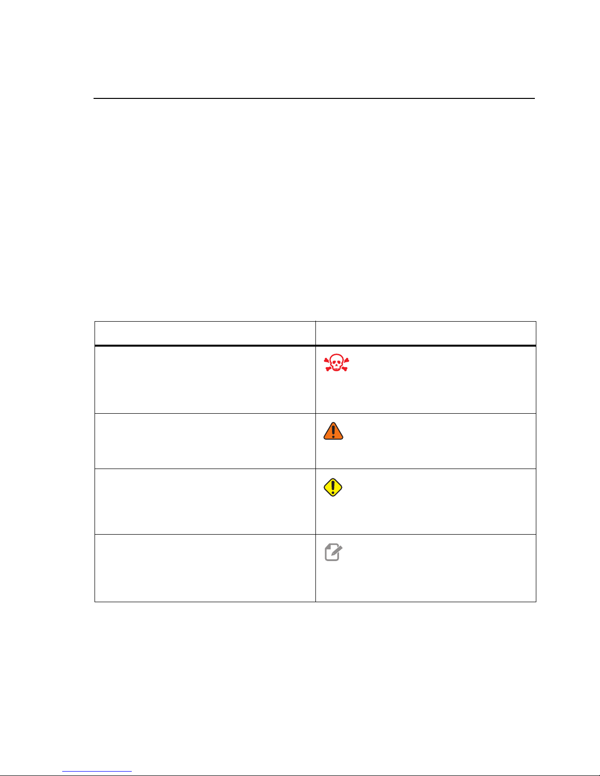
Declaration of Warnings
Throughout this manual, important statements are set off from the main text with an icon
and an associated signal word: “Danger,” “Warning,” “Caution,” or “Note.” The icon and
signal word indicate the severity of the condition or situation. Be sure to read these
statements and take special care to follow the instructions.
Description Example
Danger means that there is a condition or situation
that will cause death or severe injury if you do not
follow the instructions given.
DANGER: No step. Risk of electrocution, bodily
injury, or machine damage. Do not climb or stand
on this area.
Warning means that there is a condition or situation
that will cause moderate injury if you do not follow
the instructions given.
Caution means that minor injury or machine
damage could occur if you do not follow the
instructions given. You may also have to start a
procedure over if you do not follow the instructions in
a caution statement.
Note means that the text gives additional
information, clarification, or helpful hints.
WARNING: Never put your hands between the
tool changer and the spindle head.
CAUTION: Power down the machine before you
do maintenance tasks.
NOTE: Follow these guidelines if the machine is
equipped with the optional extended
Z-clearance table.
xi

Text Conventions Used in this Manual
Description Text Example
Code Block text gives program examples.
A Control Button Reference gives the name of a
control key or button that you are to press.
A File Path describes a sequence of file system
directories.
A Mode Reference describes a machine mode. MDI
A Screen Element describes an object on the
machine’s display that you interact with.
System Output describes text that the machine
control displays in response to your actions.
User Input describes text that you should enter into
the machine control.
Variable n indicates a range of non-negative integers
from 0 to 9.
Press
Service > Documents and Software >...
Select the
PROGRAM END
G04 P1.;
Dnn represents D00 through D99.
G00 G90 G54 X0. Y0.;
[CYCLE START].
SYSTEM tab.
xii

Contents
Chapter 1 Safety . . . . . . . . . . . . . . . . . . . . . . . . . . . . . . . . . . . . 1
1.1 General Safety Notes . . . . . . . . . . . . . . . . . . . . . . . . . . 1
1.1.1 Summary of Types of Operation for Haas Automation
Machine Tools . . . . . . . . . . . . . . . . . . . . . . . 2
1.1.2 Read Before Operating . . . . . . . . . . . . . . . . . . 4
1.1.3 Machine Environmental Limits. . . . . . . . . . . . . . . 6
1.1.4 Machine Noise Limits . . . . . . . . . . . . . . . . . . . 7
1.2 Unattended Operation . . . . . . . . . . . . . . . . . . . . . . . . . . 7
1.3 Setup Mode . . . . . . . . . . . . . . . . . . . . . . . . . . . . . . . 8
1.3.1 Machine Behavior with the Door Open . . . . . . . . . . 8
1.3.2 Robot Cells . . . . . . . . . . . . . . . . . . . . . . . . 9
1.3.3 Mist Extraction / Enclosure Evacuation . . . . . . . . . . 10
1.4 Modifications to the Machine . . . . . . . . . . . . . . . . . . . . . . 10
1.5 Improper Coolants . . . . . . . . . . . . . . . . . . . . . . . . . . . . 10
1.6 Safety Decals . . . . . . . . . . . . . . . . . . . . . . . . . . . . . . 11
1.6.1 Decal Symbols Reference . . . . . . . . . . . . . . . . . 12
1.6.2 Other Safety Information. . . . . . . . . . . . . . . . . . 16
1.7 More Information Online . . . . . . . . . . . . . . . . . . . . . . . . . 16
Chapter 2 Introduction . . . . . . . . . . . . . . . . . . . . . . . . . . . . . . . . 17
2.1 Overview. . . . . . . . . . . . . . . . . . . . . . . . . . . . . . . . . 17
2.2 UMC-750 Workstations . . . . . . . . . . . . . . . . . . . . . . . . . 17
2.3 Axis Definitions . . . . . . . . . . . . . . . . . . . . . . . . . . . . . 18
2.4 UMC-750 Specifications . . . . . . . . . . . . . . . . . . . . . . . . . 20
2.5 UMC-750P Specifications . . . . . . . . . . . . . . . . . . . . . . . . 21
Chapter 3 Integrated Coolant Tank . . . . . . . . . . . . . . . . . . . . . . . . . 25
3.1 Introduction . . . . . . . . . . . . . . . . . . . . . . . . . . . . . . . 25
3.1.1 Coolant Pump Location . . . . . . . . . . . . . . . . . . 26
3.2 Coolant Tank Clean-Out. . . . . . . . . . . . . . . . . . . . . . . . . 26
Chapter 4 Wireless Intuitive Probing System (WIPS). . . . . . . . . . . . . . . . 29
4.1 UMC WIPS Basics. . . . . . . . . . . . . . . . . . . . . . . . . . . . 29
4.2 UMC VPS Basics . . . . . . . . . . . . . . . . . . . . . . . . . . . . 29
4.3 Machine Rotary Zero Point (MRZP) Offsets . . . . . . . . . . . . . . . 30
4.3.1 Check MRZP Offsets with VPS . . . . . . . . . . . . . . 30
xiii

Chapter 5 G234 - Tool Center Point Control (TCPC). . . . . . . . . . . . . . . . . 33
5.1 G234 - Tool Center Point Control (TCPC) (Group 08) . . . . . . . . . 33
Chapter 6 G254 - Dynamic Work Offset (DWO) . . . . . . . . . . . . . . . . . . .37
6.1 G254 - Dynamic Work Offset (DWO) (Group 23) . . . . . . . . . . . . 37
Chapter 7 Setting Work and Tool Offsets . . . . . . . . . . . . . . . . . . . . . . 41
7.1 Set the B-Axis Work Offset . . . . . . . . . . . . . . . . . . . . . . . 41
7.2 Set the C-Axis Work Offset . . . . . . . . . . . . . . . . . . . . . . . 41
7.3 Set the X-, Y-, and Z-Axis Work Offsets Manually. . . . . . . . . . . . 42
7.4 Set the X-, Y-, and Z-Axis Work Offsets with WIPS . . . . . . . . . . . 46
Chapter 8 Rotary Unwind and Setting 247 . . . . . . . . . . . . . . . . . . . . . .49
8.1 Quick Rotary G28 (Home) . . . . . . . . . . . . . . . . . . . . . . . . 49
8.2 247 - Simultaneous XYZ Motion in Tool Change . . . . . . . . . . . . 49
Chapter 9 Maintenance . . . . . . . . . . . . . . . . . . . . . . . . . . . . . . . .51
9.1 Introduction . . . . . . . . . . . . . . . . . . . . . . . . . . . . . . . 51
9.2 UMC-750 Maintenance Schedule . . . . . . . . . . . . . . . . . . . . 51
9.3 More Information Online . . . . . . . . . . . . . . . . . . . . . . . . . 54
Index. . . . . . . . . . . . . . . . . . . . . . . . . . . . . . . . . . .55
xiv

Chapter 1: Safety
1.1 General Safety Notes
CAUTION: Only authorized and trained personnel may operate this equipment.
You must always act in accordance with the Operator's manual, safety
decals, safety procedures, and instructions for safe machine
operation. Untrained personnel present a hazard to themselves and
the machine.
IMPORTANT: Do not operate this machine until you have read all warnings, cautions,
and instructions.
CAUTION: The sample programs in this manual have been tested for accuracy,
but they are for illustrative purposes only. The programs do not define
tools, offsets, or materials. They do not describe workholding or other
fixturing. If you choose to run a sample program on your machine, do
so in Graphics mode. Always follow safe machining practices when
you run an unfamiliar program.
Safety
All CNC machines present hazards from rotating cutting tools, belts and pulleys, high
voltage electricity, noise, and compressed air. When you use CNC machines and their
components, you must always follow basic safety precautions to reduce the risk of personal
injury and mechanical damage.
The work area must be adequately illuminated to allow clear view and safe operation of the
machine. This includes the operator work area and all areas of the machine that might be
accessed during maintenance or cleaning. Adequate illumination is the responsibility of the
user.
Cutting tools, workholding, workpiece and coolant are beyond the scope and control of
Haas Automation, Inc. Each of these potential hazards associated with it (sharp edges,
heavy lifting considerations, chemical composition, etc) and it is the responsibility of the
user to take appropriate action (PPE, training, etc).
Cleaning of the machine is required during normal use and prior to maintenance or repair.
Optional equipment is available to aid cleaning such as washdown hoses, chip conveyors
and chip augers. Safe use of this equipment requires training and might require appropriate
PPE and is the responsibility of the user.
This operator’s manual is intended as a reference guide and is not to be the sole source of
training. Complete operator training is available from the authorized Haas distributor.
1

General Safety Notes
1.1.1 Summary of Types of Operation for Haas Automation
Machine Tools
Haas CNC Mills are intended for cutting and shaping of metals and other hard materials.
They are general purpose in nature and a list of all of those materials and types of cutting
would never be complete. Almost all cutting and shaping is performed by a rotating tool
mounted in a spindle. Rotation of the mill is not required. Some cutting operations require
liquid coolant. That coolant is also an option depending on the type of cutting.
Operations of Haas Mills are separated into three areas. They are: Operations,
Maintenance, and Service. Operations and Maintenance are intended to be performed by
a trained and qualified machine operator. This Operator's Manual contains some of the
information necessary to operate the machine. All other machine operations are to be
considered Service. Service is only to be performed by specially trained service personnel.
Operation of this machine consists of the following:
1. Machine Setup
• Machine setup is done to initially set up the tools, offsets, and fixtures required
to perform a repetitive function that later is called machine operation. Some
machine setup functions can be done with the door open but are limited to
“hold to run”.
2. Machine operating in Automatic Mode
• Automatic operation is initiated with Cycle-Start and can only be done with the
doors closed.
3. Operator loading and unloading of materials (parts)
• Parts loading and unloading is what precedes and follows an automatic
operation. This must be done with the doors open and all machine automatic
motion is stopped when the door is open.
4. Operator loading and unloading of cutting tools
• Tool loading and unloading is done less often than setup. It is often required
when a tool has become worn and must be replaced.
Maintenance only consists of the following:
1. Adding and maintaining condition of coolant
• Adding coolant and maintaining coolant concentration is required at regular
intervals. This is a normal operator function and is either done from a safe
location outside of the work enclosure or with the doors open and the machine
stopped.
2

2. Adding lubricants
• Adding lubricants for spindle and axes is required at regular intervals. These
are often months or years in length. This is a normal operator function and is
always done from a safe location outside of the work enclosure.
3. Cleaning chips out of the machine
• Cleaning out of chips is required at intervals dictated by the type of machining
performed. This is a normal operator function. It is performed with the doors
open and all of the machine operation is stopped.
Service only consists of the following:
1. Repairing of a machine that is not operating correctly
• Any machine that is not operating correctly requires service by factory trained
personnel. This is never an operator function. It is not considered
maintenance. Installation and service instructions are provided separately
from the Operator’s Manual.
2. Machine moving, unpacking, and installation
• Haas machines are shipped to a user’s location almost ready to operate. They
still require a trained service person to complete the installation. Installation
and service instructions are provided separately from the Operator’s Manual.
Safety
3. Machine packing
• Machine packing for shipment requires the same packing material supplied by
Haas in the original shipment. Packing requires a trained service person to
complete the installation. Shipping instructions are provided separately from
the Operator’s Manual.
4. Decommission, dismantle and disposal
• Machine is not expected to be disassembled for shipment; it can be moved in
its entirety in the same manner in which it was installed. Machine can be
returned to the manufacturer’s distributor for disposal; manufacturer accepts
any/all components for recycling per Directive 2002/96/EC.
5. End-of-life disposal
• End-of-life disposal must conform to the laws and regulations in the region the
machine is located. This is a jointly the responsibility of the owner and seller of
the machine. The risk analysis does not address this phase.
3

General Safety Notes
1.1.2 Read Before Operating
DANGER: Do not enter the machining area any time the machine is in motion, or
at any time that machine motion is possible. Severe injury or death
may result. Motion is possible when the power is on and the machine
is not in [EMERGENCY STOP].
Basic safety:
• This machine can cause severe bodily injury.
• This machine is automatically controlled and may start at any time.
• Consult your local safety codes and regulations before you operate the machine.
Contact your dealer if you have questions about safety issues.
• It is the machine owner’s responsibility to make sure that everyone who is involved
in installing and operating the machine is fully acquainted with the operation and
safety instructions provided with the machine, BEFORE they work with the machine.
The ultimate responsibility for safety rests with the machine owner and the individuals
who work with the machine.
• Use appropriate eye and ear protection when you operate the machine.
• Use appropriate gloves to remove processed material and to clean the machine.
• Replace windows immediately if they are damaged or severely scratched.
• Keep the side windows locked during operation (if available).
Electrical safety:
• The electrical power must meet the required specifications. Attempting to run the
machine from any other source can cause severe damage and will void the warranty.
• The electrical panel should be closed and the key and latches on the control cabinet
should be secured at all times, except during installation and service. At those times,
only qualified electricians should have access to the panel. When the main circuit
breaker is on, there is high voltage throughout the electrical panel (including the
circuit boards and logic circuits) and some components operate at high
temperatures; therefore, extreme caution is required. Once the machine is installed,
the control cabinet must be locked, with the key available only to qualified service
personnel.
• Do not reset a circuit breaker until the reason for the fault is investigated and
understood. Only Haas-trained service personnel should troubleshoot and repair
Haas equipment.
• Do not press [POWER UP] on the control pendant before the machine is fully
installed.
4

Safety
Operation Safety:
• Do not operate the machine unless the doors are closed and the door interlocks are
functioning correctly.
• Check for damaged parts and tools before you operate the machine. Any part or tool
that is damaged should be properly repaired or replaced by authorized personnel. Do
not operate the machine if any component does not appear to be functioning
correctly.
• Rotating cutting tools can cause severe injury. When a program runs, the mill table
and spindle head can move rapidly at any time.
• Improperly clamped parts machined at high speeds/feeds may be ejected and
puncture the enclosure. It is not safe to machine oversized or marginally clamped
parts.
Release of person trapped in the machine:
• No person should ever be located inside the machine during operation.
• In the unlikely event that a person is trapped inside the machine the emergency stop
button should be immediately be depressed and the person removed.
• If the person is pinched or entangled the machine should be powered off; then the
machine axes can be moved by use of a large external force in the direction required
to free the person.
Recover from a jam or blockage:
• Of the chip conveyor - Follow the cleaning instructions on the Haas Resource Center
(diy.haascnc.com). If necessary, close the doors and reverse the conveyor so the
jammed part or material is accessible, and remove. Use lifting equipment or get
assistance for lifting heavy and awkward parts.
• Of a tool and material/part - Close the doors, press [RESET] to clear and displayed
alarms. Jog the axis so the tool and material are clear.
• Of the Automatic Tool Changer/tool and spindle - Press [RECOVER] and follow the
on-screen instructions.
• If the alarms do not reset or you are unable to clear a blockage, contact your Haas
Factory Outlet (HFO) for assistance.
Follow these guidelines when you work with the machine:
• Normal operation - Keep the door closed and guards in place (for non-enclosed
machines) while the machine operates.
• Part loading and unloading – An operator opens the door, completes the task, closes
the door, and then presses [CYCLE START] (starting automatic motion).
• Machining job set-up – When set-up is complete, turn the set-up key to lock out
set-mode and remove the key.
• Maintenance / Machine Cleaner– Press [EMERGENCY STOP] or [POWER OFF] on
the machine before you enter the enclosure.
5

General Safety Notes
Periodic maintenance of machine safety features:
• Inspect door interlock mechanism for proper fit and function.
• Inspect safety windows and enclosure for damage or leaks.
• Verify all enclosure panels are in place.
Door Safety Interlock maintenance:
• Inspect the door interlock, verify the door interlock key is not bent, misaligned, and
that all fasteners are installed.
• Inspect the door interlock itself for any signs of obstruction or misalignment.
• Immediately replace an components of the Door Safety Interlock system that do not
meet this criteria.
Door Safety Interlock testing:
• With the machine in run mode, close the machine door, run the spindle at 100 RPM,
pull the door and verify the door does not open.
Machine Enclosure and Safety Glass maintenance and testing:
Routine Maintenance:
• Visually inspect the enclosure and safety glass for any signs of distortion, breakage
or other damage.
• Replace the Lexan windows after 7 years or if they are damaged or severely
scratched.
• Keep all safety glass and machine windows clean to allow proper viewing of the
machine during operations.
• A daily visual inspection of the machine enclosure to verify all panels are in place
should be performed.
Testing of machine enclosure:
• No testing of the machine enclosure is necessary.
6

1.1.3 Machine Environmental Limits
This table list the environmental limits for safe operation:
T1.1: Environmental Limits (Indoor Use Only)
Minimum Maximum
Operating Temperature 41 °F (5.0 °C) 122 °F (50.0 °C)
Storage Temperature -4 °F (-20.0 °C) 158 °F (70.0 °C)
Ambient Humidity 20% relative, non-condensing 90% relative, non-condensing
Altitude Sea Level 6,000 ft. (1,829 m)
CAUTION: Do not operate the machine in explosive atmospheres (explosive
vapors and/ or particulate matter).
Safety
1.1.4 Machine Noise Limits
CAUTION: Take precautions to prevent hearing damage from machine/machining
noise. Wear ear protection, change your application (tooling, spindle
speed, axis speed, fixturing, programmed path) to reduce noise, or
restrict access to machine area during cutting.
Typical noise levels at the operator’s position during normal operation are as follows:
• A-Weighted sound pressure level measurements will be 69.4dB or lower.
• C-Weighted instantaneous sound pressure levels will be 78.0dB or lower.
• LwA (sound power level A-weighted) will be 75.0dB or lower.
NOTE: Actual noise levels while cutting material are greatly affected by the
user’s choice of material, cutting tools, speeds and feeds, workholding
and other factors. These factors are application specific and are
controlled by the user, not Haas Automation Inc.
7

Unattended Operation
1.2 Unattended Operation
Fully enclosed Haas CNC machines are designed to operate unattended; however, your
machining process may not be safe to operate unmonitored.
As it is the shop owner’s responsibility to set up the machine safely and use best practice
machining techniques, it is also the owner’s responsibility to manage the progress of these
methods. You must monitor your machining process to prevent damage, injury, or loss of
life if a hazardous condition occurs.
For example, if there is the risk of fire due to the material machined, then you must install
an appropriate fire suppression system to reduce the risk of harm to personnel, equipment,
and the building. Contact a specialist to install monitoring tools before machines are
allowed to run unattended.
It is especially important to select monitoring equipment that can immediately detect a
problem and perform an appropriate action without human intervention.
1.3 Setup Mode
All Haas CNC machines are equipped with locks on the operator doors and a key switch
on the side of the control pendant to lock and unlock setup mode. Generally, setup mode
status (locked or unlocked) affects how the machine operates when the doors are opened.
Setup mode should be locked out (the keyswitch in the vertical, locked position) at most
times. In locked mode, the enclosure doors are locked closed during CNC program
execution, spindle rotation or axis movement. The doors automatically unlock when the
machine is not in cycle. Many machine functions are unavailable with the door open.
When unlocked, setup mode allows a skilled machinist more access to the machine to set
up jobs. In this mode, machine behavior is dependent on whether the doors are opened or
closed. Opening the doors when the machine is in cycle stops motion and reduces spindle
speed. The machine allows several functions in setup mode with the doors opened, usually
at reduced speed. The following charts summarize the modes and allowed functions.
Machines with software version 100.17.000.1016 or higher have Parameter 2083, Setup
Mode Safety Type, that affects the machine’s Setup mode. When Parameter 2083 is set to
Normal, the machine Setup and Run modes behave as outlined in the table that follows.
When Parameter 2083 is set to Strict, both the Setup and Run modes adhere to the Run
mode behaviors. Contact your local Haas Factory Outlet to set Parameter 2083 to your
desired setting on your machine.
DANGER: Do not attempt to override safety features. Doing so makes the
machine unsafe and voids the warranty.
8

1.3.1 Machine Behavior with the Door Open
CW
CCW
750 RPM Max.
750
RPM Max.
0%
0%
CHIP
FWD
CHIP
REV
CHIP
FWD
CHIP
REV
YX
Z
G00
G01
For safety, machine operations stop when the door is open and the setup keyswitch is
locked. The unlocked position allows limited machine functions with the door open.
T1.2: Setup / Run Mode Limited Overrides with the Machine Doors Open
Machine Function Keyswitch Locked Keyswitch Unlocked
Maximum Rapid Not allowed. Not allowed.
Safety
Cycle Start Not allowed. No machine
motion or program execution.
Spindle
Tool Change Not allowed. Not allowed.
Next Tool Not allowed. Not allowed.
Opening the doors while a
program runs
Conveyor motion Allowed, but you must press
[CW] / [CCW]
Allowed, but you must press
and hold
Maximum 750 RPM.
Not allowed. The door is
locked.
and hold
in reverse.
[CW] or [CCW].
[CHIP REV] to run
Not allowed. No machine motion
or program execution.
Allowed, but maximum 750 RPM.
Allowed, but axis motion stops
and the spindle slows to a
maximum of 750 RPM. The doors
lock during tool changes and
some canned cycles.
Allowed, but you must press and
hold [CHIP REV] to run in
reverse.
9

Modifications to the Machine
1.3.2 Robot Cells
A machine in a robot cell is allowed to run a program while the door is open, regardless of
the position of the Run-Setup key. While the door is open, the spindle speed is limited to
the lower of the factory RPM limit or Setting 292, Door Open Spindle Speed Limit. If the
door is opened while the spindle RPM is above the limit, the spindle will decelerate to the
limit RPM. Closing the door removes the limit and the programmed RPM is restored.
This open-door condition is allowed only while a robot communicates with the CNC
machine. Typically, an interface between the robot and the CNC machine addresses the
safety of both machines.
Robot cell setup is beyond the scope of this manual. Work with a robot-cell integrator and
your HFO to correctly set up a safe robot cell.
1.3.3 Mist Extraction / Enclosure Evacuation
The Mill products have a provision installed that will allow for a mist extractor to be attached
to the machine (except CM & GR models). There is also an optional enclosure exhaust
system available that helps keep the mist out of the machine enclosure.
It is entirely up to the owner/operator to determine if and what type of mist extractor is best
suited for the application.
The owner/operator assumes all responsibility for the installation of the mist extraction
system.
1.4 Modifications to the Machine
Haas Automation, Inc. is not responsible for damage caused by modifications you make to
your Haas machine(s) with parts or kits not manufactured or sold by Haas Automation, Inc.
The use of such parts or kits may void your warranty.
Some parts or kits manufactured or sold by Haas Automation, Inc. are considered
user-installable. If you choose to install these parts or kits yourself, be sure to completely
read the accompanying installation instructions. Make sure you understand the procedure,
and how to do it safely, before you begin. If you have any doubts about your ability to
complete the procedure, contact your Haas Factory Outlet (HFO) for assistance.
1.5 Improper Coolants
Coolant is an important part of many machining operations. When it is correctly used and
maintained, coolant can improve part finish, lengthen tool life, and protect machine
components from rust and other damage. Improper coolants, however, can cause
significant damage to your machine.
Such damage can void your warranty, but it can also introduce hazardous conditions to
your shop. For example, coolant leaks through damaged seals could create a slipping
hazard.
10

Improper coolant use includes, but is not limited to, these points:
• Do not use plain water. This causes machine components to rust.
• Do not use flammable coolants.
• Do not use straight or “neat” mineral-oil products. These products cause damage to
rubber seals and tubing throughout the machine. If you use a minimum-quantity
lubrication system for near-dry machining, use only the recommended oils.
Machine coolant must be water-soluble, synthetic oil-based or synthetic-based coolant or
lubricant.
NOTE: Be sure to maintain your coolant mixture to keep the coolant
concentrate at acceptable levels. Improperly maintained coolant
mixtures can allow machine components to rust. Rust damage is not
covered by your warranty.
Ask your HFO or your coolant dealer if you have questions about the specific coolant that
you plan to use. The Haas Resource Center website has videos and other general
information about coolant use and maintenance. You can also scan the code below with
your mobile device to directly access this information.
Safety
1.6 Safety Decals
The Haas factory puts decals on your machine to quickly communicate possible hazards.
If decals become damaged or worn, or if you need additional decals to emphasize a
particular safety point, contact your Haas Factory Outlet (HFO).
NOTE: Never alter or remove any safety decal or symbol.
Be sure to familiarize yourself with the symbols on the safety decals. The symbols are
designed to quickly tell you the type of information they give:
• Yellow Triangle - Describes a hazard.
• Red Circle with Slash-Through - Describes a prohibited action.
11

Safety Decals
123
• Green Circle - Describes a recommended action.
• Black Circle - Gives information about machine or accessory operation.
F1.1: Example Safety Decal Symbols: [1] Hazard Description, [2] Prohibited Action, [3]
Recommended Action.
1.6.1 Decal Symbols Reference
This section gives explanations and clarifications for the safety symbols you will see on
your machine.
T1.3: Hazard Symbols – Yellow Triangles
Symbol Description
Moving parts can entangle, trap, crush, and cut.
Keep all parts of your body away from machine parts when they move, or
whenever motion is possible. Motion is possible when the power is on and
the machine is not in [EMERGENCY STOP].
Secure loose clothing, hair, etc.
Remember that automatically controlled devices can start at any time.
Do not touch rotating tools.
Keep all parts of your body away from machine parts when they move, or
whenever motion is possible. Motion is possible when the power is on and
the machine is not in
Sharp tools and chips can easily cut skin.
[EMERGENCY STOP].
12

Symbol Description
The Regen is used by the spindle drive to dissipate excess power and will
get hot.
Always use care around the Regen.
There are high voltage components on the machine that can cause
electrical shock.
Always use care around high voltage components.
Long tools are dangerous, especially at spindle speeds higher than 5000
RPM. The tools can break and eject from the machine.
Remember that machine enclosures are intended to stop coolant and
chips. Enclosures may not stop broken tools or thrown parts.
Always check your setup and tooling before you start machining.
Safety
Machining operations can create hazardous chips, dust or mist. This is
function of the materials being cut, the metalworking fluid and cutting tools
used and the machining speeds/feeds.
It is up to the owner/operator of the machine to determine if personal
protective equipment such as safety goggles or a respirator is required
and also if a mist extraction system is needed. All enclosed models
have a provision for connecting a mist extraction system.
Always read and understand the Safety Data Sheets (SDS) for the
workpiece material, the cutting tools and the metalworking fluid.
13

Safety Decals
T1.4: Prohibited Action Symbols – Red Circles with Slash-Through
Symbol Description
Do not enter the machine enclosure when the machine is capable of
automatic motion.
When you must enter the enclosure to complete tasks, press
[EMERGENCY STOP] or power off the machine. Put a safety tag on
the control pendant to alert other people that you are inside the machine,
and that they must not turn on or operate the machine.
Do not machine ceramics.
Do not attempt to load tools with the spindle dogs misaligned with the
cutouts in the toolholder V-Flange.
14
Do not machine flammable materials.
Do not use flammable coolants.
Flammable materials in particulate or vapor form can become explosive.
The machine enclosure is not designed to contain explosions or extinguish
fire.
Do not use pure water as coolant. This will cause machine components to
rust.
Always use a rust-inhibitive coolant concentrate with water.

T1.5: Recommended Action Symbols – Green Circles
Symbol Description
Keep the machine doors closed.
Always wear safety glasses or goggles when you are near a machine.
Airborne debris can cause eye damage.
Always wear hearing protection when you are near a machine.
Machine noise can exceed 70 dBA.
Safety
Make sure the spindle dogs are correctly aligned with the cutouts in the
toolholder V-flange.
Note the location of the tool release button. Press this button only when
you are holding the tool.
Some tools are very heavy. Handle these tools carefully; use both hands
and have someone press the tool release button for you.
15

More Information Online
T1.6: Informational Symbols – Black Circles
Symbol Description
Maintain the recommended coolant concentration.
A “lean” coolant mixture (less concentrated than recommended) may not
effectively prevent machine components from rusting.
A “rich” coolant mixture (more concentrated than recommended) wastes
coolant concentrate without further benefit over the recommended
concentration.
1.6.2 Other Safety Information
You may find other decals on your machine, depending on the model and options installed.
Be sure to read and understand these decals. These are examples of other safety decals
in English. You can contact your Haas Factory Outlet (HFO) to get these decals in other
languages.
1.7 More Information Online
For updated and supplemental information, including tips, tricks, maintenance procedures,
and more, go to DIY.HaasCNC.com
You can also scan this code with your mobile device to directly access the “Best Practices”
page on the Resource Center, which includes information about safety.
.
16

Chapter 2: Introduction
A
B
C
2.1 Overview
This operator’s manual supplement describes the unique features and functions of the
UMC series of machines. Refer to your Mill Operator’s Manual for control operation,
programming, and other general mill information.
You can find specific details about the UMC family, including information that is beyond the
scope of this document, at www.HaasCNC.com.
2.2 UMC-750 Workstations
F2.1: This diagram illustrates the UMC-750 three operator zones.
• A: Operator Station.
• B: Check and Maintain Lubricants.
• C: Check and Maintain Coolant, Coolant Pumps and Chip Conveyor.
Introduction
17

Axis Definitions
B
C
-35°
+110°
-
+
2.3 Axis Definitions
F2.2: This diagram illustrates the (5) axes available on the UMC-750 / UMC-750SS.
18

F2.3: This diagram illustrates the (5) axes available on the UMC-750P.
A
+
-
B+
B-
+ 45°
- 45°
Introduction
19

UMC-750 Specifications
2.4 UMC-750 Specifications
T2.1: UMC-750 Specifications
Travels
S.A.E Metric
X Axis 30" 762 mm
Y Axis 20" 508 mm
Z Axis 20" 508 mm
C-Axis Rotation 360° Rotation
B-Axis Tilt -35° to +110°
Spindle Nose to Table (~ min.) 4" 102 mm
Spindle Nose to Table (~ max.) 24" 610 mm
For detailed machine dimensions, including work envelope information, refer to the UMC-750
Machine Layout Drawing on www.haascnc.com.
Table
Width 19.7" 500 mm
Length 24.8" 630 mm
T-Slot Width 5/8" 16 mm
T-Slot Center Distance 2.48" 63 mm
Number of Standard T-Slots 7
Max. Weight on Table (evenly
distributed)
660 lb 300 kg
20

T2.2: General Requirements
General Requirements
Air Required 4 scfm, 100 psi 113 L/min, 6.9 bar
Coolant Capacity 75 gal 284 L
Power Requirement, Low Voltage 195-260 VAC / 100A
Power Requirement, High Voltage 354-488 VAC / 50A
Machine Weight 18,000 lb 8165 kg
T2.3: Standard Features
Standard Features
Tool Center Point Control (TCPC), Dynamic Work Offsets (DWO), Remote Jog Handle*,
Second Home*, Macros*, Spindle Orientation (SO)*, Coordinate Rotation and Scaling (COORD)*,
TSC-Ready, Wireless Intuitive Probing System (WIPS)
*Refer to the Mill Operator’s Manual (96-8210) for information on these features.
Introduction
2.5 UMC-750P Specifications
T2.4: UMC-750P Specifications
Travels
S.A.E Metric
X Axis 30" 762 mm
Y Axis 20" 508 mm
Z Axis 20" 508 mm
A-Axis Rotation 360° Rotation
B-Axis Tilt -45° to +45°
Spindle Nose to Table (max.) 25" 635 mm
21

UMC-750P Specifications
Travels
S.A.E Metric
Spindle Nose to Table (min.) 5" 127 mm
For detailed machine dimensions, including work envelope information, refer to the UMC-750
Machine Layout Drawing on www.haascnc.com.
Table
Width 14.75" 375 mm
Length 33" 838 mm
T-Slot Width 5/8" 16 mm
T-Slot Center Distance N/A
Number of Standard T-Slots 1
Max. Weight on Table (evenly
distributed)
660 lb 300 kg
T2.5: General Requirements
General Requirements
Air Required 4 scfm, 100 psi 113 L/min, 6.9 bar
Coolant Capacity 75 gal 284 L
Power Requirement, Low Voltage 195-260 VAC / 100A
Power Requirement, High Voltage 354-488 VAC / 50A
Machine Weight 18,000 lb 8165 kg
22

T2.6: Standard Features
Standard Features
Tool Center Point Control (TCPC), Dynamic Work Offsets (DWO), Remote Jog Handle*,
Second Home*, Macros*, Spindle Orientation (SO)*, Coordinate Rotation and Scaling (COORD)*,
TSC-Ready, Wireless Intuitive Probing System (WIPS)
*Refer to the Mill Operator’s Manual (96-8210) for information on these features.
Introduction
23

UMC-750P Specifications
24

Integrated Coolant Tank
Chapter 3: Integrated Coolant Tank
3.1 Introduction
The UMC-750 coolant tank is integrated into the machine base.
F3.1: UMC -750 Integrated Coolant Tank
25

Coolant Tank Clean-Out
2
4
5
3
1
3.1.1 Coolant Pump Location
The coolant pumps are on the tool changer side of the machine, behind the chip conveyor.
The standard coolant box filter is mounted below the standard coolant pump.
F3.2: UMC-750 Coolant Pump Location: [1] Chip Tray, [2] Gate Filter, [3] Coolant Box Filter, [4]
Standard Coolant Pump, [5] TSC Coolant Pump
3.2 Coolant Tank Clean-Out
To clean out the coolant tank:
1. Remove the coolant pumps.
2. Remove and empty the coolant box filter.
3. Remove and empty the chip tray.
4. Remove and clean the gate filter.
5. Use a wet/dry vacuum or similar device to remove the used coolant from the tank.
6. For more thorough cleaning, open the coolant tank access panels in the bottom of
the work space.
26

F3.3: Coolant Tank Access Panels
7. Add coolant to the tank and install the gate filter, coolant box filter, chip tray, and
coolant pumps. Install the coolant tank access panels if you removed them.
Integrated Coolant Tank
27

Coolant Tank Clean-Out
28

Wireless Intuitive Probing System (WIPS)
Chapter 4: Wireless Intuitive Probing
System (WIPS)
4.1 UMC WIPS Basics
The Wireless Intuitive Probing System (WIPS) comes standard with the UMC-750. This
system can perform all of the standard probe routines found in the WIPS templates, and
also includes special probe routines specifically for the UMC. These special probe routines
use a tooling ball on a magnetic base to automatically find the machine’s centers of rotation.
Refer to page 5 for more information on this process.
Normally, you use WIPS to set tool and work offsets, but the UMC-750 includes a master
gauge length tool in case you need to set offsets manually (if, for example, a probe stylus
breaks or the batteries lose power). The gage length tool included with your machine has
a unique length that is etched on the tool.
NOTE: If you set the tool length offsets manually, you must also set the Z-Axis
work offset manually.
4.2 UMC VPS Basics
The Visual Programing System (VPS) (which contains Wireless Intuitive Probing (WIPS))
comes standard with the UMC-750. This system can perform all of the standard probe
routines found in the WIPS templates, and also includes special probe routines specifically
for the UMC. These special probe routines use a tooling ball to automatically find the
machine’s centers of rotation. Refer to page 5 for more information on this process.
Normally, you use WIPS to set tool and work offsets, but the UMC-750 includes a master
gauge length tool in case you need to set offsets manually (if, for example, a probe stylus
breaks or the batteries lose power). The gage length tool included with your machine has
a unique length that is etched on the tool.
NOTE: If you set the tool length offsets manually, you must also set the Z-Axis
work offset manually.
29

Machine Rotary Zero Point (MRZP) Offsets
4.3 Machine Rotary Zero Point (MRZP) Offsets
The Machine Rotary Zero Point (MRZP) Offsets are control settings that define the location
of the centers of rotation for the rotary table relative to the linear axes home position.
Settings 255, 256, and 257 define the following:
255 – MRZP X Offset
Location of the B Axis rotary center point relative to the X Axis home position.
256 – MRZP Y Offset
Location of the C Axis rotary center point relative to the Y Axis home position.
257 – MRZP Z Offset
Location of the B Axis rotary center point relative to the Z Axis home position.
The value stored in these settings is the distance from the home position of a linear axis to
the center of rotation of a rotary axis. Setting 9 determines if the values are shown in inches
or millimeters.
The Machine Rotary Zero Point (MRZP) Offsets are set at the factory.
4.3.1 Check MRZP Offsets with VPS
The MRZP offsets can change over time. To make sure the UMC-750, UMC-750SS MRZP
Offsets are correct do the following:
1. Place the tooling ball in the center of the X axis.
IMPORTANT: Make sure that the tooling ball is tightly attached to the calibration
assembly. Do not over tighten the tooling ball.
30

F4.1: Calibration Tooling Ball
2. Place the work probe in the spindle.
3. Position the work probe over the tooling ball.
4. Navigate to [EDIT]>VPS>PROBING>CALIBRATION>MRZP and select B-Axis Tilt
C-Axis Rotary Finish Set and press [ENTER].
Wireless Intuitive Probing System (WIPS)
5. Type gage ball diameter and press [ENTER].
6. Follow the prompts to generate the probe program. Enter MDI mode and press
[CYCLE START].
The program generates the G-code and runs the program.
F4.2: B-Axis Tilt C-Axis Rotary MRZP Finish Set Generated Program
7. The program automatically places values in macro variables #10121 through
#10123. These variables show the machine rotary zero point axis travel distance
from the home position in the X, Y, and Z Axes.
8. If the MRZP locations have changed, enter the values from macro variables #10121,
#10122, and #10123 into Settings 255, 256, and 257.
31

Machine Rotary Zero Point (MRZP) Offsets
32

G234 - Tool Center Point Control (TCPC)
Chapter 5: G234 - Tool Center Point
Control (TCPC)
5.1 G234 - Tool Center Point Control (TCPC)
(Group 08)
G234 Tool Center Point Control (TCPC) is a software feature in the Haas CNC control that
allows a machine to correctly run a contouring 4- or 5-axis program when the workpiece is
not located in the exact location specified by a CAM-generated program. This eliminates
the need to repost a program from the CAM system when the programmed and the actual
workpiece locations are different.
The Haas CNC control combines the known centers of rotation for the rotary table (MRZP)
and the location of the workpiece (e.g., active work offset G54) into a coordinate system.
TCPC makes sure that this coordinate system remains fixed relative to the table; when the
rotary axes rotate, the linear coordinate system rotates with them. Like any other work
setup, the workpiece must have a work offset applied to it. This tells the Haas CNC control
where the workpiece is located on the machine table.
The conceptual example and illustrations in this section represent a line segment from a
full 4- or 5-axis program.
NOTE: For clarity, the illustrations in this section do not depict workholding.
Also, as conceptual, representative drawings, they are not to scale
and may not depict the exact axis motion described in the text.
The straight line edge highlighted in Figure F5.1 is defined by point (X0, Y0, Z0) and point
(X0, Y-1., Z0). Movement along the Y Axis is all that is required for the machine to create
this edge. The location of the workpiece is defined by work offset G54.
33

G234 - Tool Center Point Control (TCPC) (Group 08)
X0, Y0, Z0
(G54)
X0, Y-1., Z0
X
Y
Z
F5.1: Location of Workpiece Defined by G54
In Figure F5.2, the B and C Axes have been rotated 15 degrees each. To create the same
edge, the machine needs to make an interpolated move with the X, Y, and Z Axes. Without
TCPC, you would need to repost the CAM program for the machine to correctly create this
edge.
F5.2: G234 (TCPC) Off and the B and C Axes Rotated
TCPC is invoked in Figure F5.3. The Haas CNC control knows the centers of rotation for
the rotary table (MRZP), and the location of the workpiece (active work offset G54). This
data is used to produce the desired machine motion from the original CAM-generated
program. The machine follows an interpolated X-Y-Z path to create this edge, even though
the program simply commands a single-axis move along the Y Axis.
34

F5.3: G234 (TCPC) On and the B and C Axes Rotated
X0, Y-1., Z0
X0, Y0, Z0
G234 Program Example
%
O00003 (TCPC SAMPLE)
G20
G00 G17 G40 G80 G90 G94 G98
G53 Z0.
T1 M06
G00 G90 G54 B47.137 C116.354 (POSITION ROTARY AXES)
G00 G90 X-0.9762 Y1.9704 S10000 M03 (POSITION LINEAR AXES)
G234 H01 Z1.0907 (TCPC ON WITH LENGTH OFFSET 1, APPROACH IN
Z-AXIS)
G01 X-0.5688 Y1.1481 Z0.2391 F40.
X-0.4386 Y0.8854 Z-0.033
X-0.3085 Y0.6227 Z-0.3051
X-0.307 Y0.6189 Z-0.3009 B46.784 C116.382
X-0.3055 Y0.6152 Z-0.2966 B46.43 C116.411
X-0.304 Y0.6114 Z-0.2924 B46.076 C116.44
X-0.6202 Y0.5827 Z-0.5321 B63.846 C136.786
X-0.6194 Y0.5798 Z-0.5271 B63.504 C136.891
X-0.8807 Y0.8245 Z-0.3486
X-1.1421 Y1.0691 Z-0.1701
X-1.9601 Y1.8348 Z0.3884
G49 (TCPC OFF)
G00 G53 Z0.
G53 B0. C0.
G53 Y0.
M30
%
G234 Programmer’s Notes
G234 - Tool Center Point Control (TCPC)
35

G234 - Tool Center Point Control (TCPC) (Group 08)
These key presses and program codes cancel G234:
•[EMERGENCY STOP]
•[RESET]
•[HANDLE JOG]
•[LIST PROGRAM]
• M02 – Program End
• M30 – Program End and Reset
• G43 – Tool Length Compensation +
• G44 – Tool Length Compensation -
• G49 – G43 / G44 / G143 Cancel
These codes will NOT cancel G234:
• M00 – Program Stop
• M01 – Optional Stop
These key presses and program codes impact G234:
• G234 invokes TCPC and cancels G43.
• When using tool length compensation, either G43 or G234 must be active. G43 and
G234 cannot be active at the same time.
• G234 cancels the previous H-code. An H-code must therefore be placed on the same
block as G234.
• G234 cannot be used at the same time as G254 (DWO).
36
These codes ignore 234:
• G28 – Return to Machine Zero Through Optional Reference Point
• G29 – Move to Location Thru G29 Reference Point
• G53 – Non-Modal Machine Coordinate Selection
• M06 – Tool Change
Invoking G234 (TCPC) rotates the work envelope. If the position is close to the travel limits,
the rotation can put the current work position outside of travel limits and cause an over
travel alarm. To solve this, command the machine to the center of the work offset (or near
the center of the table on a UMC), and then invoke G234 (TCPC).
G234 (TCPC) is intended for simultaneous 4- and 5-axis contouring programs. An active
work offset (G54, G55, etc.) is required to use G234.

G254 - Dynamic Work Offset (DWO)
Chapter 6: G254 - Dynamic Work Offset
(DWO)
6.1 G254 - Dynamic Work Offset (DWO) (Group 23)
G254 Dynamic Work Offset (DWO) is similar to TCPC, except that it is designed for use
with 3+1 or 3+2 positioning, not for simultaneous 4- or 5-axis machining. If the program
does not make use of the tilt and rotary Axes, there is no need to use DWO.
CAUTION: The B-Axis value of the work offset you use with G254 MUST be zero.
With DWO, you no longer need to set the workpiece in the exact position as programmed
in the CAM system. DWO applies the appropriate offsets to account for the differences
between the programmed workpiece location and the actual workpiece location. This
eliminates the need to repost a program from the CAM system when the programmed and
actual workpiece locations are different.
The control knows the centers of rotation for the rotary table (MRZP) and the location of the
workpiece (active work offset). This data is used to produce the desired machine motion
from the original CAM-generated program. Therefore, it is recommended that G254 be
invoked after the desired work offset is commanded, and after any rotational command to
position the 4th and 5th axes.
After G254 is invoked, you must specify an X, Y, and Z Axis position before a cutting
command, even if it recalls the current position. The program should specify the X- and Y
Axis position in one block and the Z Axis in a separate block.
CAUTION: Before rotary motion, use a G53 Non-Modal Machine Coordinate
motion command to safely retract the tool from the workpiece and
allow clearance for the rotary motion. After the rotary motion finishes,
specify an X-, Y-, and Z-Axis position before a cutting command, even
if it recalls the current position. The program should specify the X- and
Y-Axis position in one block and the Z-Axis position in a separate
block.
CAUTION: Be sure to cancel G254 with G255 when your program does
simultaneous 4- or 5-axis machining.
37

G254 - Dynamic Work Offset (DWO) (Group 23)
X0, Y0, Z0
X1, Y-1, Z0
NOTE: For clarity, the illustrations in this section do not depict workholding.
The block in the figure below was programmed in the CAM system with the top center hole
located at the center of the pallet and defined as X0, Y0, Z0.
F6.1: Original Programmed Position
In the figure below, the actual workpiece is not located in this programmed position. The
center of the workpiece is actually located at X1, Y-1, Z0, and is defined as G54.
F6.2: Center at G54, DWO Off
DWO is invoked in the figure below. The control knows the centers of rotation for the rotary
table (MRZP), and the location of the workpiece (active work offset G54). The control uses
this data to apply the appropriate offset adjustments to make sure that the proper toolpath
is applied to the workpiece, as intended by the CAM-generated program. This eliminates
the need to repost a program from the CAM system when the programmed and actual
workpiece locations are different.
38

F6.3: Center with DWO On
X0, Y0, Z0
G254 Program Example
%
O00004 (DWO SAMPLE) ;
G20 ;
G00 G17 G40 G80 G90 G94 G98 ;
G53 Z0. ;
T1 M06 ;
G00 G90 G54 X0. Y0. B0. C0. (G54 is the active work offset
for) ;
(the actual workpiece location) ;
S1000 M03 ;
G43 H01 Z1. (Start position 1.0 above face of part Z0.) ;
G01 Z-1.0 F20. (Feed into part 1.0) ;
G00 G53 Z0. (Retract Z with G53) ;
B90. C0. (ROTARY POSITIONING) ;
G254 (INVOKE DWO) ;
X1. Y0. (X and Y position command) ;
Z2. (Start position 1.0 above face of part Z1.0) ;
G01 Z0. F20. (Feed into part 1.0 ) ;
G00 G53 Z0. (Retract Z with G53) ;
B90. C-90. (ROTARY POSITIONING) ;
X1. Y0. (X and Y position command) ;
Z2. (Start position 1.0 above face of part Z1.0) ;
G01 Z0. F20. (Feed into part 1.0 ) ;
G255 (CANCEL DWO) ;
B0. C0. ;
M30 ;
%
G254 Programmer’s Notes
G254 - Dynamic Work Offset (DWO)
39

G254 - Dynamic Work Offset (DWO) (Group 23)
These key presses and program codes will cancel G254:
•[EMERGENCY STOP]
•[RESET]
•[HANDLE JOG]
•[LIST PROGRAM]
• G255 – Cancel DWO
• M02 – Program End
• M30 – Program End and Reset
These codes will NOT cancel G254:
• M00 – Program Stop
• M01 – Optional Stop
Some codes ignore G254. These codes will not apply rotational deltas:
• *G28 – Return to Machine Zero Through Optional Reference Point
• *G29 – Move to Location Through G29 Reference Point
• G53 – Non-Modal Machine Coordinate Selection
• M06 – Tool Change
*It is strongly recommended that you not use G28 or G29 while G254 is active, nor when
the B and C Axes are not at zero.
40
1. G254 (DWO) is intended for 3+1 and 3+2 machining, where the B and C Axes are
used to position only.
2. An active work offset (G54, G55, etc.) must be applied before G254 is commanded.
3. All rotary motion must be complete before G254 is commanded.
4. After G254 is invoked, you must specify an X-, Y-, and Z-Axis position prior to any
cutting command, even if it recalls the current position. It is recommended to specify
the X and Y Axes in one block, and the Z Axis in a separate block.
5. Cancel G254 with G255 immediately after use and before ANY rotary motion.
6. Cancel G254 with G255 any time simultaneous 4- or 5-axis machining is performed.
7. Cancel G254 with G255 and retract the cutting tool to a safe location before the
workpiece is repositioned.

Setting Work and Tool Offsets
Chapter 7: Setting Work and Tool
Offsets
7.1 Set the B-Axis Work Offset
If the fixture or workpiece requires you to adjust the B Axis to achieve the proper alignment
for machining, use this procedure to adjust and record the B-Axis work offset.
CAUTION: Do not use a B-Axis offset if your program uses Dynamic Work Offsets
(G254). The B-Axis offset value must be zero.
1. Adjust the B Axis until the workpiece is positioned to the same orientation established
in the program. Typically, the top surface of the fixture or workpiece is perpendicular
to the Z Axis.
2. Navigate to [OFFSET]>Work. Scroll to the work offset value used in the program
(G54 in this example).
3. Highlight the value in the B Axis column. Press [PART ZERO SET] to record the
offset.
7.2 Set the C-Axis Work Offset
NOTE: If the fixture or workpiece requires you to adjust the C Axis to achieve
the proper alignment for machining, use the following procedure to
adjust and record the C-Axis work offset.
41

Set the X-, Y-, and Z-Axis Work Offsets Manually
F7.1: Setting the C-Axis Workpiece Orientation
1. Place the workpiece on the platter (workholding not shown). Adjust the C Axis until
the workpiece is positioned to the same orientation established in the program.
Typically, a reference feature on the fixture or workpiece is parallel to the X or Y Axis.
2. Navigate to [OFFSET]>Work. Scroll to the work offset value used in the program
(G54 in this example).
3. Highlight the value in the C Axis column. Press [PART ZERO SET] to record
the offset.
7.3 Set the X-, Y-, and Z-Axis Work Offsets
Manually
NOTE: Use this procedure if the WIPS probe is disabled.
NOTE: Refer to the Haas Mill Operator’s Manual for basic offset and
toolsetting methods.
42

1. Jog the X and Y Axes to the zero position established in the program.
F7.2: UMC-750 X- and Y-Axis Zero Position
2. Navigate to [OFFSET]>Work. Scroll to the work offset value used in the program
(G54 in this example).
3. Select the X Axis column of your work coordinate offset and press [PART ZERO
SET] to set the X-Axis zero position.
4. Press [PART ZERO SET] again to set the Y-Axis zero position.
Setting Work and Tool Offsets
F7.3: X-Axis Zero Position Set and Y-Axis Zero Position Set
5. Determine a tool set plane to be used for setting all tool length offsets; for example,
use the top surface of the workpiece.
43

Set the X-, Y-, and Z-Axis Work Offsets Manually
F7.4: Example Tool Set Plane (Top of the Part)
6. Load the master gage tool included with WIPS into the spindle.
F7.5: Master Gage Tool
7. Make sure that the B and C Axes are at the same work zero point set earlier.
(G00 G90 G54 B0 C0)
44

8. Select the Z AXIS column of your work coordinate offset.
9. Jog the Z Axis to the tool set plane. Make sure that the end of the gage tool you are
using just touches the tool set plane. You will touch-off all of your tools on this
surface.
F7.6: Jog the End of the Gage Tool to the Tool Set Plane
Setting Work and Tool Offsets
10. With the Z Axis column of the work offset used in the program highlighted (G54 in this
example), press [PART ZERO SET].
11. Subtract the length of the master gage tool supplied with the machine from the value
shown in the Z Axis column. Enter this value as the offset in the Z Axis column.
For example, if the Z-Axis work offset is -7.0000 and the master gage tool length is
5.0000, the new Z-Axis work offset is -12.0000.
12. Touch-off each of the tools in your program to the Z set plane to establish their length
offsets.
45

Set the X-, Y-, and Z-Axis Work Offsets with WIPS
7.4 Set the X-, Y-, and Z-Axis Work Offsets with
WIPS
If you are not using the WIPS system, go to the Set the X-, Y-, and Z-Axis Work Offsets
Manually section, starting on page 41.
NOTE: Make sure that the tool setting probe and the work probe are
calibrated. Refer to the Haas WIPS manual (96-10002) for the
calibration procedure.
F7.7: UMC-750 Work Offset with WIPS
46

F7.8: UMC Z-Axis Work Zero Offset Start
0.25"
(6 mm)
1. Load the work probe into the spindle.
2. Make sure that the B and C Axes are at the same work zero point set earlier.
(G00 G90 G54 B0 C0). Refer to the Set the B-Axis Work Offset and Set the C-Axis
Work Offset sections if these values are not correct.
3. Set the X- and Y-Axis offsets using the standard WIPS templates as appropriate.
Refer to the WIPS manual for more information.
4. Position the work probe tip approximately 0.25" (6 mm) above the Z-Axis zero
surface.
5. Navigate to [OFFSET] Work. Scroll to the work offset value used in the program (G54
in this example).
Setting Work and Tool Offsets
6. Press the [RIGHT] cursor arrow until you reach the Probe Action sub-menu.
7. Type 11, and then press [ENTER] to assign the Single Surface Probe Action
to the offset.
8. Press [PART ZERO SET] to move to VPS.
9. Select the Z Variable.
47

Set the X-, Y-, and Z-Axis Work Offsets with WIPS
F7.9: VPS 11. Single Surface Probe
48
10. Type -.5 (or -12 if the control is set to metric measurements), and then press
[ENTER].
11. Press [CYCLE START]. The probe measures the distance to the top of the part and
records the value in the Z Axis column work offset for G54.
12. Use the tool setting probe to set each of your tool length offsets.

Rotary Unwind and Setting 247
Chapter 8: Rotary Unwind and Setting
247
8.1 Quick Rotary G28 (Home)
This feature lets you to return the rotary axis to zero within 359.99 degrees, saving time and
motion. The rotary axis will need to have rotated at least 360 degrees for the unwind feature
to be a benefit.
For example, if the rotary axis has rotated a total of 960 degrees through the course of a
program, a rotary axis zero return command without the unwind feature will cause the axis
to rotate back through all 960 degrees of rotation before the Haas CNC control considers
the axis at home.
With Quick Rotary G28 enabled, the rotary axis rotates toward zero just enough to reach
its home position; the control ignores all previous revolutions. In the example of 960
degrees of rotation, the rotary axis rotates a negative 240 degrees and stops at the
machine home position.
To use this feature, Setting 108 must be set to ON. The unwind command must be an
incremental (G91) Home command (G28).
For example:
G54 G01 F100. C960. (rotary axis TURNS 960 DEGREES CLOCKWISE)
G28 G91 C0. (rotary axis ROTATES 240 DEGREES COUNTER-CLOCKWISE
TO HOME)
8.2 247 - Simultaneous XYZ Motion in Tool Change
Setting 247 defines how the axes move during a tool change. If Setting 247 is OFF, the
Z Axis retracts first, followed by X- and Y-Axis motion. This feature can be useful in avoiding
tool collisions for some fixture configurations. If Setting 247 is ON, the axes move
simultaneously. This may cause collisions between the tool and the workpiece, due to Band C-Axis rotations. It is strongly recommended that this setting remain OFF on the
UMC-750, due to the high potential for collisions.
49

247 - Simultaneous XYZ Motion in Tool Change
50

Chapter 9: Maintenance
9.1 Introduction
Regular maintenance is important to make sure that your machine has a long and
productive life with minimal downtime. The most common maintenance tasks are simple
and you can do them yourself. You can also ask your HFO about their comprehensive
preventive maintenance program for complex maintenance tasks.
9.2 UMC-750 Maintenance Schedule
T9.1: Maintenance Schedule Table
Maintenance Item Interval
Automatic Tool Changer - SMTC
Clean the chips from the tool changer. Weekly
Maintenance
Inspect the arm plunger and adjuster
assembly.
Grease the tool changer cams. Annually
Auxiliary Filter
Replace the filter bag. Check the Gauge
Inspect the hoses for cracking. Six Months
Axis Lubrication
Inspect grease reservoir level. Monthly
Inspect the hoses for cracking. Six Months
Electrical Cabinet
Clean vector drive air vents / filter. Monthly
Enclosure
Inspect windows for damage. Daily
Inspect the door interlock operation. Daily
Six Months
51

UMC-750 Maintenance Schedule
Maintenance Item Interval
Inspect way covers and lubricate. Monthly
Minimum Quantity Lubrication
Clean the filter inside the oil reservoir. Annually
Oil Skimmer
Inspect the oil skimmer pickup tube. Six Months
Pneumatics
Inspect the spindle air regulator pressure. Weekly
Inspect the hoses for cracking. Six Months
Clean the Air Purge Solenoid. Annually
Pneumatics
Inspect the spindle air regulator pressure. Weekly
Inspect the hoses for cracking. Six Months
Clean the air purge solenoid Annually
Probe System
Check the probe batteries. Six Months
Check the probe calibration. Six Months
Rotary Axes
Inspect the oil. Annually
Replace the oil. Two Years
Replace the A-Axis counterbalance cylinder. Two Years
Standard Flood Coolant System
Clean the filter screen. As required
Inspect the coolant level. Weekly
52

Maintenance Item Interval
Inspect the coolant concentration. Weekly
Maintenance
Completely clean the coolant tank and replace
the coolant.
Clean the standard coolant filter. Six Months
Verify the coolant refill is operating correctly. Six Months
Spindle
Clean and lubricate the spindle taper. As required.
Check the spindle drawbar force. Annually
Spindle Lubrication
Inspect lubrication tank level. Monthly
Tooling
Grease the pull studs. As required.
Through Spindle Coolant (TSC)
Clean the TSC filter. Six Months
Inspect the hoses for cracking. Six Months
Six Months
Verify that the auto-clean feature is operating
correctly.
Six Months
53

More Information Online
9.3 More Information Online
For updated and supplemental information, including tips, tricks, maintenance procedures,
and more, visit the Haas Resource Center at diy.HaasCNC.com
code below with your mobile device to go directly to the Resource Center:
. You can also scan the
54

Index
A
air requirement ................................. 21, 22
C
c-axis rotary unwind................................. 49
coolant capacity
coolant pumps
location
coolant tank
access panels
................................ 21, 22
............................................ 26
........................................... 25
................................... 26
D
dynamic work offset (G254)....................... 37
L
linear axis (x,y,z) offsets
setting manually
setting with WIPS
................................ 42
............................... 46
M
machine rotary zero point (MRZP)
check with WIPS
maintenance
material
fire risk
.......................................... 51
............................................. 7
................................ 30
S
safety
decals
door interlock
during operation
electrical
glass window
introduction
keyswitch operation
maintenance
part loading/unloading
robot cells
safety decals
standard layout
symbol reference
safety information
setup mode
............................................. 11
..................................... 5
................................. 4
........................................... 4
..................................... 6
....................................... 1
............................. 8
...................................... 5
......................... 5
......................................... 9
................................. 11
............................... 12
.................................... 16
.............................................. 8
T
tool center point control ............................ 33
G54 and
tooling ball
.......................................... 34
............................................. 29
U
unattended operation................................. 7
O
operation
unattended
........................................ 7
P
power requirements........................... 21, 22
W
WIPS.................................................... 29
master gage length tool
work offset, setting
.............................................. 41
b axis
.............................................. 41
c axis
workholding
safety and
......................................... 5
...................... 29
55

56
 Loading...