

Page 1

Haas Technical Publications
Manual_Archive_Cover_Page Rev A
any other party automatically voids the factory warranty.
June 6, 2013
HAAS SERVICE AND OPERATOR MANUAL ARCHIVE
SL-Series Service Manual 96-8710 RevC English June 2001
• This content is for illustrative purposes.
• Historic machine Service Manuals are posted here to provide information for Haas machine owners.
• Publications are intended for use only with machines built at the time of original publication.
• As machine designs change the content of these publications can become obsolete.
• You should not do mechanical or electrical machine repairs or service procedures unless you are qualied
and knowledgeable about the processes.
• Only authorized personnel with the proper training and certication should do many repair procedures.
WARNING: Some mechanical and electrical service procedures can be
extremely dangerous or life-threatening.
Know your skill level and abilities.
All information herein is provided as a courtesy for Haas machine owners
for reference and illustrative purposes only. Haas Automation cannot be held
responsible for repairs you perform. Only those services and repairs that are
provided by authorized Haas Factory Outlet distributors are guaranteed.
Only an authorized Haas Factory Outlet distributor should service or repair a
Haas machine that is protected by the original factory warranty. Servicing by
Page 2

June 2001
TROUBLESHOOTING
COMMON ABBREVIATIONS USED IN HAAS MACHINES
AC Alternating Current
AMP Ampere
APC Automatic Pallet Changer
APL Automatic Parts Loader
ASCII American Standard Code for Information Interchange
ATC Automatic Tool Changer
ATC FWD Automatic Tool Change Forward
ATC REV Automatic Tool Changer Reverse
AWG American Wire Gauge
BHCS Button Head Cap Screw
CAD Computer Assisted Design
CAM Computer Assisted Machining
CB Circuit Breaker
CC Cubic Centimeter
CCW Counter Clockwise
CFM Cubic Feet per Minute
CNC Computerized Numeric Control
CNCR SPINDLE Concurrent Spindle with axis motion
CRC Cyclic Redundancy Check Digit
CRT Cathode Ray Tube
CW Clockwise
DB Draw Bar
DC Direct Current
DGNOS Diagnostic
DIR Directory
DNC Direct Numerical Control
DOS Disk Operating System
ENA CNVR Enable Conveyor
EOB End Of Block
EOF End Of File
EPROM Erasable Programmable Read Only Memory
E-Stop Emergency Stop
FHCS Flat Head Cap Screw
FT Foot
FU Fuse
FWD Forward
GA Gauge
HHB Hex Head Bolts
HP Horse Power
HS Horizontal Series Of Machining Centers
ID Inside Diameter
IGBT Isolated Gate Bipolar Transistor
IN Inch
IOPCB Input Output Printed Circuit Board
LAN Local Area Network
LB Pound
LED Light Emitting Diode
LO CLNT Low Coolant
LOW AIR PR Low Air Pressure
LVPS Low Voltage Power Supply
MB Megabyte (1 million)
MCD RLY BRD M-Code Relay Board
MDI Manual Data Input
96-8710 rev C
1
Page 3

TROUBLESHOOTING
MEM Memory
M-FIN M-Code Finished
MM Millimeter
MOCON Motor Control
MOTIF Motor Interface
MSG Message
MSHCP Metric Socket Head Cap Screw
NC Numerical Control
NC Normally Closed
NO Normally Open
OD Outside Diameter
OPER Operator
P Pocket
PARAM Parameter
PCB PrintedCircuit Board
PGM Program
POR Power On Reset
POSIT Positions
PROG Program
PSI Pounds Per Square Inch
PWM Pulse Width Modulation
RAM Random Access Memory
REPT RIG TAP Repeat Rigid Tap
RET Return
REV CNVR Reverse Conveyor
RJH Remote Jog Handle
RPDBDN Rotary Pallet Draw Bar Down
RPDBUP Rotary Pallet Draw Bar Up
RPM Revolutions Per Minute
S Spindle Speed
SDIST Servo Distribution PCB
SFM Surface Feet Per Minute
SHCS Socket Head Cap Screw
SIO Serial Input/Output
SKBIF Serial Key Board Inter Face PCB
SMTC Side Mount Tool Changer
SP Spindle
T Tool Number
TC Tool Changer
TIR Total Indicated Runout
TNC Tool Nose Compensation
TRP Tool Release Piston
TS Tail Stock
TSC Through The Spindle Coolant
VF Vertical Mill (very first)
VF-E Vertical Mill- Extended
VMC Vertical Machining Center
WAN Wide Area Network
June 2001
2
96-8710 rev C
Page 4

June 2001
TROUBLESHOOTING
1. TROUBLESHOOTING
This section is intended for use in determining the solution to a known problem. Solutions given are intended to
give the individual servicing the CNC a pattern to follow in, first, determining the problems source and second,
solving the problem.
The troubleshooting tips are organized in this section according to the area of the CNC that may be giving sign
of a problem. (Ex.: Out-of round circles in drilling will be found under the heading General Machine Operation Accuracy).
If the problem you are experiencing cannot be found under the heading you expect, please try several other
possible headings. If the problem is still not found, contact Haas Automation for further details.
BEFORE YOU BEGIN:
USE COMMON SENSE
Many problems are easily overcome by correctly evaluating the situation. All machine operations are composed
of a program, tools, and tooling. You must look at all three before blaming one as the fault area. If a bored hole
is chattering because of an overextended boring bar, dont expect the machine to correct the fault. Dont
suspect machine accuracy if the vise bends the part. Dont claim hole mis-positioning if you dont first centerdrill the hole.
FIND THE PROBLEM FIRST
Many mechanics tear into things before they understand the problem, hoping that it will appear as they go. We
know this from the fact that more than half of all warranty returned parts are in good working order. If the
spindle doesnt turn, remember that the spindle is connected to the gear box, which is connected to the
spindle motor, which is driven by the spindle drive, which is connected to the I/O BOARD, which is driven by
the MOCON, which is driven by the processor. The moral here is dont replace the spindle drive if the belt is
broken. Find the problem first; dont just replace the easiest part to get to.
DONT TINKER WITH THE MACHINE
There are hundreds of parameters, wires, switches, etc., that you can change in this machine. Dont start
randomly changing parts and parameters. Remember, there is a good chance that if you change something,
you will incorrectly install it or break something else in the process. Consider for a moment changing the
processors board. First, you have to download all parameters, remove a dozen connectors, replace the board,
reconnect and reload, and if you make one mistake or bend one tiny pin it WONT WORK. You always need to
consider the risk of accidentally damaging the machine anytime you work on it. It is cheap insurance to
double-check a suspect part before physically changing it. The less work you do on the machine the better.
96-8710 rev C
3
Page 5

TROUBLESHOOTING
1.1 GENERAL MACHINE OPERATION
MACHINE NOT RUNNING
Machine cannot be powered on.
Check input voltage to machine (see "Electrical Service").
Check main circuit breaker at top right of electrical cabinet; switch must be at the on position.
Check overvoltage fuses (see "Electrical Service").
Check wiring to POWER OFF button on front control panel.
Check wiring to AUTO OFF relay to IOPCB.
Check connection between 24V transformer and K1 contactor
Check IOPCB (see "Electrical Service").
Check POWER PCB (see "Electrical Service").
Machine can be powered on, but turns off by itself.
June 2001
Check settings #1 and #2 for Auto Off Timer or Off at M30.
Check alarm history for OVERVOLTAGE or OVERHEAT shutdown.
Check AC power supply lines for intermittent supply.
Check wiring to POWER OFF button on front control panel.
Check connection between 24V transformer and K1 contactor.
Check IOPCB (see "Electrical Service").
Check Parameter 57 for Power Off at E-STOP.
Check MOTIF or MOCON PCB (see "Electrical Service").
Machine turns on, keyboard beeps, but no CRT display.
Check for power connections to CRT from IOPCB. Check for green POWER LED at front of CRT.
Close doors and Zero Return machine (possible bad monitor).
Check video cable (760) from VIDEO PCB to CRT.
Check for lights on the processor.
Machine turns on, CRT works, but no keyboard keys work.
Check keyboard cable (700B) from VIDEO to KBIF PCB.
Check keypad (see "Electrical Service").
Check KBIF PCB (see "Electrical Service").
4
96-8710 rev C
Page 6

June 2001
TROUBLESHOOTING
VIBRATION
Vibration is a subjective evaluation with perceptions varying among individuals, making it difficult to determine in
mild cases if there is an actual problem. In obvious cases, it is a matter of determining the source - which is
not easy, since all parts rotate together and sound can be transferred readily. Vibrations also need to be
distinguished from noise such as a bad bearing. We will assume that vibrations would be something that could
be felt by putting your hand on the spindle ring. One crude method of measurement would be to take an
indicator on a magnetic base extended 10 inches between the turret and spindle housing and observe the
reading of the indicator. A reading of more than .001 would indicate excessive vibration. The two common
sources of noise are the spindle and axis drives. Most complaints about vibration, accuracy, and finish can be
attributed to incorrect machining practices such as poor quality or damaged tooling, incorrect speeds or feeds,
or poor fixturing. Before concluding that the machine is not working properly, ensure that good machining
practices are being observed. These symptoms will not occur individually (Ex. A machine with backlash may
vibrate heavily, yielding a bad finish). Put all of the symptoms together to arrive at an accurate picture of the
problem.
Machine vibrates while spindle is on and is not cutting. Sometimes only at specific RPM.
If the spindle alone causes vibration of the machine this is usually caused by the belt/pulley drive system
or the chuck jaws are not centered correctly.
Machine vibrates while jogging the axis with the jog handle.
The HAAS control uses very high gain accelerations curves. This vibration as you jog is simply the
servos quickly trying to follow the handle divisions. If this is a problem, try using a smaller division on
the handle. You will notice the vibration more at individual clicks than when you are turning the handle
faster. This is normal.
The machine vibrates excessively in a cut.
This is a tough one to call because machining practices come into play. Generally speaking, the least
rigid element of a cut is the tool because it is the smallest part. Any cutter will vibrate if pushed beyond
its tensile strength. In order to eliminate the machine as the source of the problem, you need to check
the spindle and the backlash of the axes as described in the following sections. Once machining
practices have been eliminated as the source of vibration, observe the machine in both operation and
cutting air. Move the axes (individually) without the spindle turning and then turn the spindle without
moving the axes. Isolate whether the vibration comes from the spindle head or from an axis.
96-8710 rev C
5
Page 7

TROUBLESHOOTING
ACCURACY
Before you complain of an accuracy problem, please make sure you follow these simple dos and donts:
Ensure that the machine has been sufficiently warmed up before cutting parts. This will eliminate
mispositioning errors caused by thermal growth of the leadscrews (see "Thermal Growth" section).
Dont ever use a wiggler test indicator for linear dimensions. They measure in an arc and have sine/cosine
errors over larger distances.
Dont use magnetic bases as accurate test stops. The high accel/decel of the axis can cause them to
move.
Dont attach test points to the sheet metal of the spindle head.
Dont check for accuracy/repeatability using an indicator with a long extension.
Ensure that test indicators and stops are absolutely rigid and mounted to machined casting surfaces
Check a suspected error with another indicator or method for verification.
Ensure that the indicator is parallel to the axis being checked to avoid tangential reading errors.
Center drill holes before using jobber length drills if accuracy is questioned.
Once machining practices have been eliminated as the source of the problem, determine specifically what
the machine is doing wrong.
June 2001
Diameters are out of round
Check that tooling and machining practices are correct. Bores will be out of round due to tool deflection
much more frequently than due to spindle bearing problems.
Drill
Diameters are incorrect in X-axis
Ensure the tool probe is set up correctly (settings, etc.)
Ensure tool offsets are coorect. Note that the coordinate system (FANUC, YASNAC, HAAS) must be
selected before setting tools.
Ensure Parameter 254, Spindle Center, is set correctly.
Check for thermal growth of the X-axis leadscrew (see Thermal Growth section).
6
96-8710 rev C
Page 8
June 2001
TROUBLESHOOTING
Center holes are malformed
Ensure tooling is tight.
Ensure Parameter 254, Spindle Center, is set correctly.
Check spindle to turret pocket alignment. It may be out of alignment due to a crash or misadjustment.
Check for thermal growth of the X-axis leadscrew (see Thermal Growth section).
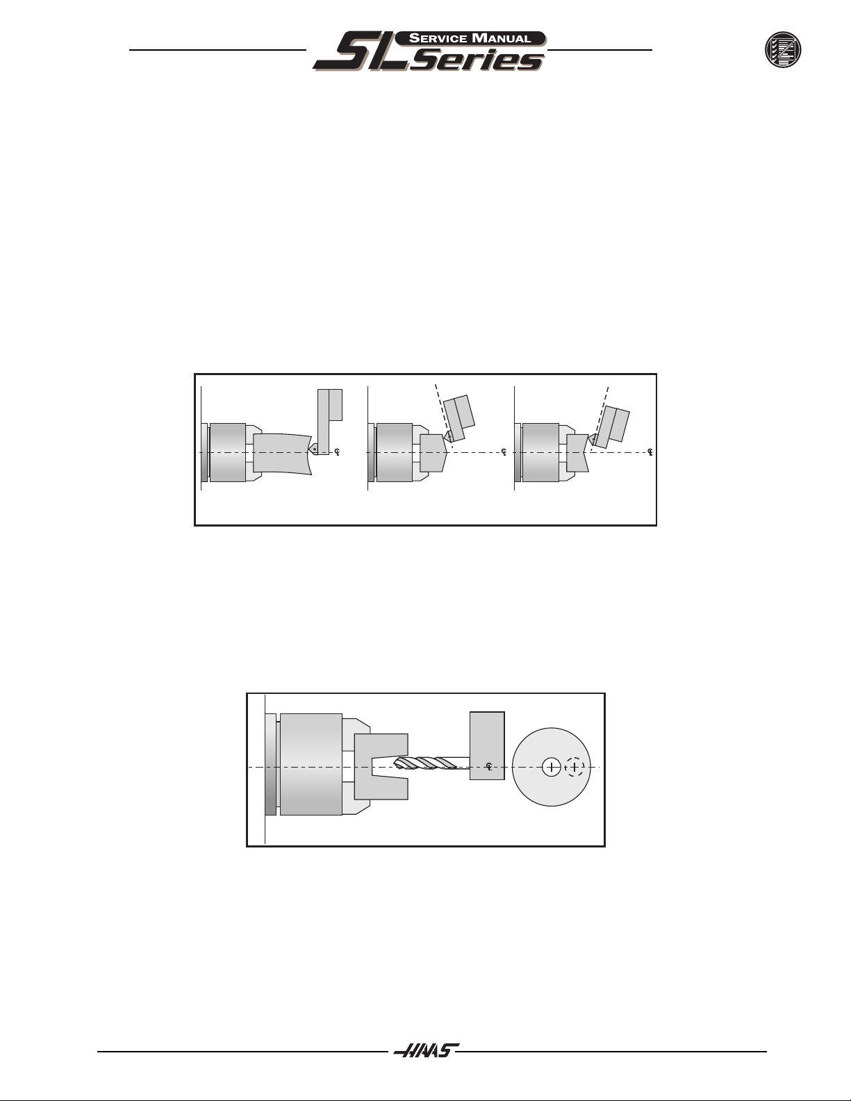
Part faces are conical
Wedge may be out of alignment due to a crash.
Check tooling setup. Turning long, unsupported parts may cause conical part faces.
Check for thermal growth of the leadscrews (see Thermal Growth section).
C
L
Part/Tooling Problem Geometry Problem
C
L
C
L
Bores are tapered
Check that tooling and machining practices are correct. Bores will be tapered if the tooling is inappropriate,
the speeds and feeds are incorrect, or coolant is not getting to the cutting tool when required.
Although it is rare, the spindle may be out of alignment due to a crash
Check that the turret face is parallel with x-axis.
C
L
96-8710 rev C
7
Page 9
TROUBLESHOOTING
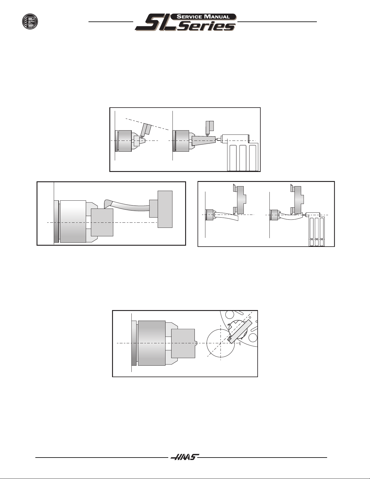
Outside diameter (O.D.) is tapered
Check tooling setup. Turning long, unsupported parts can cause a tapered O.D.
Check tailstock setup. Excessive hold pressure on the tailstock can distort parts.
Spindle to Z-axis may be out of alignment (not parallel).
Program around it. Reduce depth of final rough cut and finish pass to reduce part deflection.
June 2001
C
L
Poor Geometry
C
L
Material left after facing a part
Ensure tooling is correct.
Ensure turret is aligned to X-axis travel.
Ensure Parameter 254, Spindle Center, is set correctly.
C
L
C
L
Poor Technique
C
L
Material Left After Facing Part
8
96-8710 rev C
Page 10

June 2001
TROUBLESHOOTING
FINISH
Machining yields a poor finish
Check the condition of the tooling and the spindle.
Ensure turret is clamped.
Ensure tooling is tight.
Check tooling for chatter or lack of rigidity.
Check the balance of the chuck, part, and fixture.
Check for backlash.
Check turret alignment.
THERMAL GROWTH
A possible source of accuracy and positioning errors is thermal growth of the leadscrews. As the machine
warms up, the leadscrews expand in both linear axes (X and Z), causing accuracy and positioning errors. This
is especially critical in jobs that require high accuracy.
NOTE: Thermal growth will be more noticeable in the X-axis, since errors will be
doubled when cutting a diameter.
Verify Thermal Growth
There are a number of ways to verify the problem. The following procedure will verify thermal growth of the Xaxis reversed-anchored leadscrew in a machine that has not been warmed up:
1. Home the machine. In MDI mode, press POSIT and PAGE DOWN to the OPER page.
2. Jog to an offset location. Select the X-axis and press the ORIGIN key to zero it.
3. Press the OFSET key, then scroll down to G110 (or any unused offset). Cursor to X and press the
PART ZERO SET key. This will set X) at this position.
4. Enter a program that will start at the new zero position, rapid a certain distance in the X direction,
feed the final .25 inches slowly, and then repeat the X movement.
96-8710 rev C
9
Page 11

TROUBLESHOOTING
5. In order to set up the indicator, run the program in SINGLE BLOCK mode, and stop it when X is at
the end of its set travel. Set the magnetic base on the spindle retainer ring or other rigid surface,
with the indicator tip touching the turret in the X-axis, and zero it.
6. Exit SINGLE BLOCK mode, and run the program for a few minutes. Enter SINGLE BLOCK mode
again, stop the program when X is at the beginning of its travel, and take a final reading on the
indicator. If the problem is thermal growth, the indicator will show a difference in the X position.
June 2001
NOTE: Ensure the indicator setup is correct as described in Accuracy section. Error
in setup are common, and often incorrectly appear to be thermal growth.
7. A similar program can be written to test for thermal growth in the Z-axis.
Solutions
Since there are many variables that affect thermal growth, such as the ambient temperature of the shop and
program feed rates, it is difficult to give one solution for all problems.
Thermal growth problems can generally be eliminated by running a warm-up program for approximately 20
minutes before machining parts. The most effective warm-up is to run the current program, at an offset Z
position before the part. This will allow the leadscrews to warm up to the correct temperature and stabilize.
Once the machine is at temperature, the leadscrews won't expand any further, unless they are allowed to cool
down. A warm-up program should be run after each time the machine is left idle.
10
96-8710 rev C
Page 12

June 2001
TROUBLESHOOTING
1.2 SPINDLE
NOT TURNING
Spindle not turning
If there are any alarms, see Alarms section.
Check that the spindle turns freely when machine is off.
If spindle is still not turning, replace MOCON PCB.
Disconnect the drive belt. If the spindle will not turn, it is seized and must be replaced.
For Brush machines only:
If spindle drive does not light the RUN LED, check forward/reverse commands from IOPCB.
Check that the drawtube piston is not bound against the spindle shaft on the air cylinder style.
Check the wiring of analog speed command from MOTIF PCB to spindle drive (cable 720).
Disconnect the drive belt. If the spindle will not turn, it is seized and must be replaced.
NOTE: Before using the replacement spindle, the cause of the previous failure must
NOISE
Most noise attributed to the spindle actually lie in the motor or drive belt of the machine. Isolate the sources of
noise as follows:
Excessive noise coming from the spindle head area.
be determined.
Remove the left end covers and check the machines drive belt tension.
Run the motor with the drive belt disconnected. If the noise persists, the problem lies with the motor. If it
disappears, go on to the next step.
Check for the correct amount of lubrication to the spindle bearings (1cc per hour) in an air mist lubricated
spindle.
96-8710 rev C
11
Page 13

TROUBLESHOOTING
VECTOR DRIVE
To properly troubleshoot the Vector Drive, use the following questions as a guide:
What alarms are generated?
When does the alarm occur?
Is the Vector Drive top fault light on?
Is there a fault light on any of the servo amplifiers?
Does the alarm reset?
Does the spindle motor turn at all?
Does the spindle turn freely by hand?
Have the C-axis parameters been confirmed?
What is the input voltage to the vector drive unit?
What does the DC Bus voltage measure? (320 VDC to 345 VDC)
Does the DC Bus voltage displayed on the diagnostic page match the measured DC Bus voltage?
All of the questions above must be answered. The DC Bus voltage should be between 320 VDC to 345 VDC
with the machine powered up but not running. If the voltage is not in this range, adjust the taps on the main
line transformer until this voltage range is achieved. There is a possibility the drive is faulty, but low Bus
voltage can also be caused by a shorted REGEN load or a shorted amplifier.
June 2001
If the DC Bus voltage is below 50 VDC and never goes any higher, perform Steps 1-6.
1. With the machine powered up, is the green POWER-ON L.E.D. lit? If not, replace the Vector
Drive unit.
2. Power down the machine. Disconnect the REGEN load (terminals 1 and 2 on the Vector Drive
unit) and measure the resistance from each wire-to-chassis ground (open) and between the wire
leads. The resistance should be 8.6 ohms for machines with 20/15 Vector drives and HT10K mills
equipped with 40/30 drives. All other machines with 40/30 drives should measure 6 ohms. If not,
replace the REGEN load or cabling.
3. Disconnect cable 490 at terminals 2 and 3 of the Vector Drive and from the servo amplifiers. With
a multimeter in the diode mode, place the red meter lead to the +HV terminal and the black meter
lead to the -HV terminal of each amplifier. The meter should read open.
4. Reverse the leads: Place the red meter lead on the -HV terminal and the black lead on the +HV
terminal. The meter should read .7 ohms in both instances. If not, replace the faulty amplifier.
5. Measure the resistance between terminals 1 and 3 of the Vector Drive. The meter should read
greater than 100K ohms. If not, the Vector Drive is faulty.
6. If the green POWER-ON L.E.D. was lit (from Step 2), leave both 490 cables (2 and 3) disconnected from the drive and power up the machine.
a. Does the DC Bus voltage come up? If not, the Vector Drive is faulty.
b. Measure the voltage between terminals 1 and 3. The voltage should be 300
VDC or more. If not, the Vector Drive is faulty.
If both a and b check out okay, there is a problem with either the amplifiers or the REGEN load.
12
96-8710 rev C
Page 14

June 2001
TROUBLESHOOTING
If the fault occurs upon acceleration -or- the spindle accelerates slowly -or- the spindle
makes noise, do the following:
7. Disconnect the output cables to the spindle motor. Turn on the machine and press <RESET>. Do
not command the spindle to turn. With a volt meter, measure the DC voltage between each output
phase (terminals 9, 10, and 11) to the 320V RTN (terminal 3). The meter should read 165 VDC in
each case, else one phase is faulty.
8. Measure the resistance across the motor wires from phase to phase and from each phase to
chassis. The meter should read .1 ohms phase-to-phase and open phase-to-chassis.
If the fault occurs upon deceleration or acceleration just as the spindle reaches its specified speed, or if an overvoltage alarm (119) occurred, do the following:
9. Disconnect the REGEN load resistors (terminals 1 and 2) and measure the resistance from each
wire lead-to-chassis ground and between the wire leads. The meter should read open lead-toground, and 6 ohms between the leads for machines with 40/30 Vector drives and 8.6 ohms
between the leads on machines with 20/15 Vector drives and HT10K mills.
10. Measure the resistance from terminal 1 to terminal 3. If the resistance is less than 100K, the drive
is faulty.
11. With the REGEN load left disconnected, power-up the machine and command a spindle speed of
700 RPM (300 RPM for lathes in high gear). Press <RESET> while monitoring the DC voltage
between terminal 1 and terminal 3. The voltage should read 330 VDC and then drop to less than
50 VDC momentarily. If not, that drive is faulty. If the voltage at RESET was okay and the alarm
was resettable, the REGEN load should be replaced even if the resistance appears to be
96-8710 rev C
13
Page 15

TROUBLESHOOTING
1.3 TRANSMISSION (SL 30 AND 40)
The transmission cannot be serviced in the field and must be replaced as a unit. Never remove the motor from
the transmission, as this will damage the transmission and void the warranty.
NOISE
Excessive or unusual noise coming from transmission.
Operate the machine in both high and low gears. Monitor for noise in both gear positions, and determine if the
noise varies with the motor or output shaft speed.
If the noise only occurs in one gear throughout the entire RPM range of that gear position, the problem lies
with the transmission, and it must be replaced.
If the noise occurs in both gear positions, disconnect the drive belts (see Transmission section, Mechani-
cal Service) and repeat the previous step. If the noise persists, the transmission is damaged and must be
replaced.
Disconnect the drive belts (see Transmission section, Mechanical Service) and run the machine in high
gear. Command a change of direction and listen for a banging noise in the transmission as the machine
slows down to zero RPM and speeds back up in reverse. If the noise occurs, the motor has failed and the
transmission must be replaced.
June 2001
GEARS WILL NOT CHANGE
Machine will not execute a gear change.
Check the voltage to the gear shifter motor. The voltage between pins 2 and 3 should be approximately
+28V when high gear is commanded and -28V when low gear is commanded. If these voltages are correct,
the gear shifter motor has failed and the transmission must be replaced. If these voltages are incorrect, the
cabling or transmission power supply is at fault.
INCORRECT GEAR SELECTED OR SENSED
Spindle speed is not consistent with selected gear.
Monitor the discrete inputs and outputs SP HIG and SP LOW on the diagnostics display while command-
ing high and low gear. The output SP HIG should be 1 when high gear is selected, and SP LOW should be
1 when low gear is selected. The inputs SP HIG and SP LOW should be 0 when that gear is engaged, and
should both be 1 when the transmission is between gears. These inputs should never read 0 at the same
time.
If any of these inputs/outputs are incorrect, either the gear change limit switches or the wiring to the I/O PCB is
at fault. The limit switches are located inside the transmission, and cannot be replaced.
14
96-8710 rev C
Page 16

June 2001
TROUBLESHOOTING
1.4 SERVO MOTORS / LEADSCREWS
NOT OPERATIN G
All problems that are caused by servo motor failures should also register an alarm. Check the alarm history to
determine the cause of the problem before any action is taken.
Servo motor is not functioning.
Check the power cable from rear electrical cabinet to ensure connection is tight.
Encoder is faulty or contaminated (Alarms 139-142, 153-156, 165-168, 182-185). Replace motor
assembly on brushless machines
Open circuit in motor (Alarms 139-142, 153-156, 182-185). Replace motor assembly ("Axis Motor
Removal / Installation").
Motor has overheated, resulting in damage to the interior components (Alarms 135-138, 176).
Replace motor assembly ("Axis Motor Removal/Installation").
Wiring is broken, shorted, or missing shield (Alarms 153-156, 175, 182-185).
Motor has overheated; no damage to the interior components. OVERHEAT alarm has been
triggered. After thorough check of motor (DO NOT DISASSEMBLE!), take necessary steps to
eliminate the problem and alarm to resume operation. If motor is still inoperable, replace motor
assembly ("Axis Motor Removal/Installation").
Check for broken or loose coupling between the servo motor and the lead screw. Replace or repair
the coupling ("Axis Motor Removal/Installation")
Check for a damaged lead screw, and replace if necessary ("Lead Screw Removal and Installation"
section).
NOTE: If a lead screw fails, it is most often due to a failed bearing sleeve. When
NOISE
Lead screw noise is usually caused by a lack of lubrication and is usually accompanied by heating. Other
causes are misalignment, bearing sleeve damage, or ball nut damage. Check the alarm history of the machine
and look for axis overcurrent and following error alarms.
NOTE: Do not replace lead screws or bearing sleeves without due consideration; they
replacing the lead screw in an older machine, always replace the bearing
sleeve with the current angular contact bearing sleeve ("Bearing Sleeve
Removal and Installation" section).
are extremely durable and reliable. Verify that customer complaints are not due
to tooling, programming, or fixturing problems.
96-8710 rev C
15
Page 17

TROUBLESHOOTING
Servo motor noise.
Disconnect the servo motor from the lead screw and rotate by hand. If the noise persists, replace
the motor assembly ("Axis Motor Removal/Installation" section).
If motor noise is caused by motor bearings, replace motor.
Lead screw noise.
Ensure oil is getting to the lead screw through the lubrication system. Look for a plugged metering
valve.
Check for damage to the bearing sleeve.
June 2001
NOTE: The current angular contact design sleeve has a fixed pre-load; it cannot be
adjusted.
Run the axis back and forth. The motor will get very hot if the bearing sleeve is damaged. If so, turn
the axis by hand and feel for roughness in the lead screw. Loosen the clamp nuts at both ends of
the lead screw. If the symptom disappears, replace the bearing sleeve. Be certain to check for
damage to the lead screw shaft where the bearing sleeve is mounted. If the noise persists, the lead
screw is damaged and must be replaced. When replacing the lead screw in an older machine,
always replace the bearing sleeve with the current angular contact design bearing sleeve.
Misalignment in the lead screw itself will tend to cause the lead screw to tighten up and make
excessive noise at both ends of the travel. The ballnut may get hot. Misalignment radially at the
yoke where the lead screw ball nut mounts is indicated by heating up of the ball nut on the lead
screw, and noise and tightness throughout the travel of the lead screw. Misalignment at the yoke
where the ball nut mounts is indicated by noise and tightness at both ends of the travel of the lead
screw. The ball nut may get hot.
NOTE: Customer complaints of Lead Screw noise may not indicate a bad screw.
Screws from different manufacturers produce varying levels of noise. Often
machines are built with two or more different brands of screws in the same
machine. If complaints are generated about one axis screw in comparison to
another, it is possible that the screws are simply sourced from different
manufacturers.
16
ACCURACY / BACKLAS H
Accuracy complaints are usually related to tooling, programming, or fixturing problems. Eliminate these
possibilities before working on the machine.
Poor Z-axis accuracy.
Check for a loose encoder on the servo motor. Also, ensure the key in the motor or the lead screw is in
place and the coupling is tight (Brush motors only).
Check parameters for that axis.
Check for backlash in the lead screw as outlined below.
96-8710 rev C
Page 18
June 2001
TROUBLESHOOTING
Initial Preparation-
Turn the lathe ON. ZERO RET the machine and move the carriage to the approximate center of its travel in the
Z-axis. Move the turret to the approximate center of the X-axis travel.
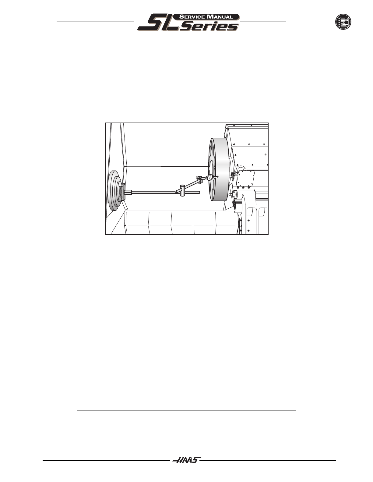
X-Axis:
1. Place a dial indicator and base on the spindle retaining ring with the tip of the indicator positioned
on the outside diameter of the turret, as shown in Fig. 1.4-1
Fig. 1.4-1 Dial indicator in position to check X-axis.
2. Set dial indicator and the Distance to go display in HANDLE JOG mode to zero as follows:
Zero the dial indicator.
Press the MDI button on the control panel.
Press the HANDLE JOG button on the control panel.
The Distance to go display on the lower right hand corner should read: X=0 Z=0
3. Set the rate of travel to .001 on the control panel and jog the machine .010 in the positive (+) X
direction. Jog back to zero (0) on the display. The dial indicator should read zero (0) ± .0001.
4. Repeat step 3 in the negative (-) direction.
TOTAL DEVIATION BETWEEN THE DIAL INDICATOR AND THE CONTROL PANEL DISPLAY
SHOULD NOT EXCEED .0002.
An alternate method for checking backlash is to place the dial indicator as shown in Fig. 4-1 and manually
push on the turret in both directions. The dial indicator should return to zero after releasing the turret.
NOTE: The servos must be on to check backlash by this method.
96-8710 rev C
17
Page 19
TROUBLESHOOTING
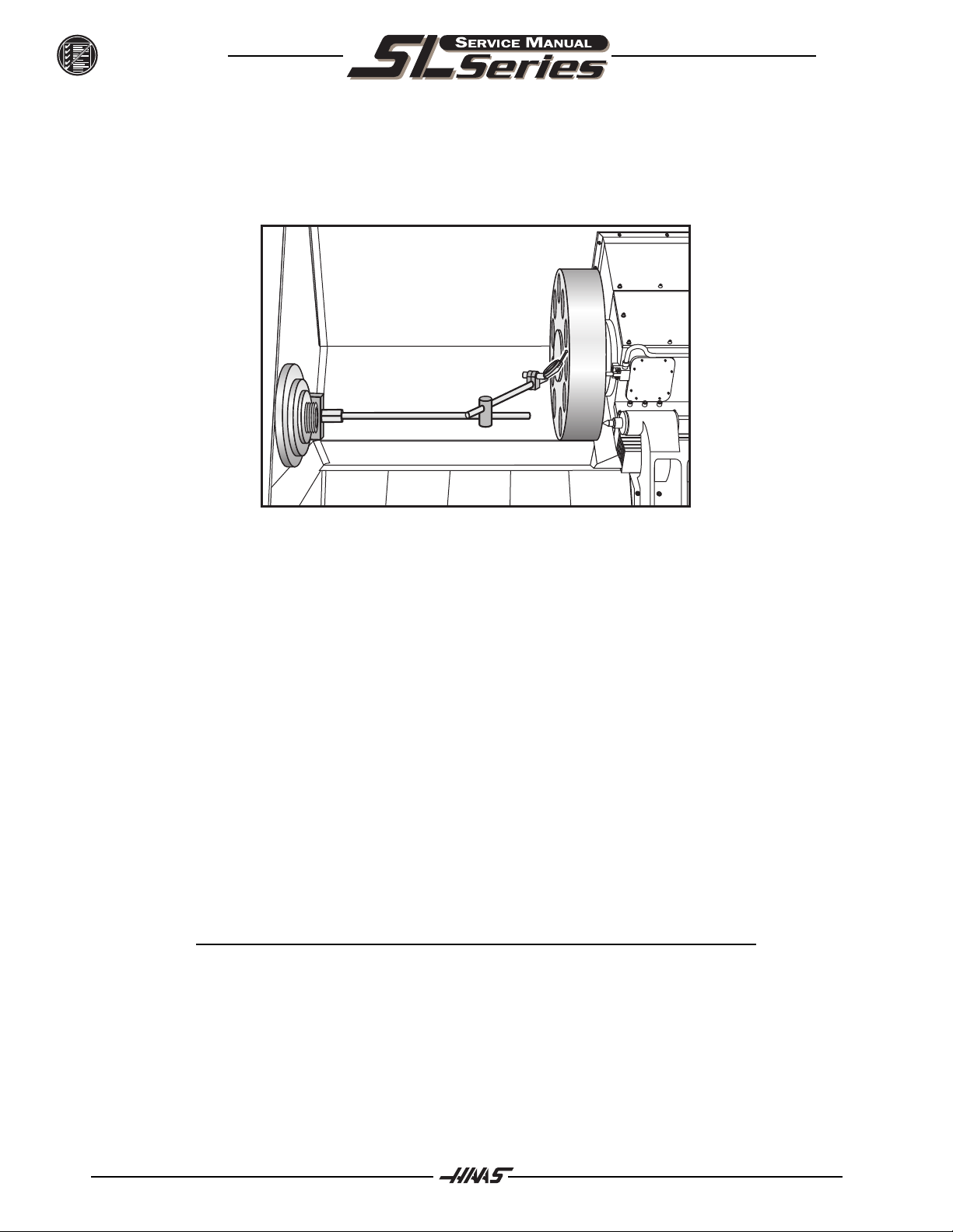
Z-Axis:
1. Place a dial indicator and base on the spindle retaining ring with the indicator tip positioned on the
face of the turret as shown in Fig. 1.4-2.
June 2001
Fig. 1.4-2 Dial indicator in position to check Z-axis
2. Set dial indicator and the Distance to go display in the HANDLE JOG mode to zero as follows:
Zero the dial indicator.
Press the MDI button on the control panel.
Press the HANDLE JOG button on the control panel. The Distance to go: display on the lower
right hand corner should read: X=0, Z=0
3. Set the rate of travel to .001 on the control panel and jog the machine .010 in the positive (+) Z
direction. Jog back to zero (0) on the display. The dial indicator should read (0) ± .001.
4. Repeat Step 3 in the negative (-) direction.
TOTAL DEVIATION BETWEEN THE DIAL INDICATOR AND THE CONTROL PANEL DISPLAY
SHOULD NOT EXCEED .0002.
An alternate method for checking backlash is to place the dial indicator as shown in Fig. 4-2 and manually
push on the turret in both directions. The dial indicator should return to zero after releasing the turret.
NOTE: The servos must be on to check backlash by this method.
18
96-8710 rev C
Page 20

June 2001
TROUBLESHOOTING
VIBRATION
Excessive servo motor vibration.
Check all Parameters of the suspected axis against the Parameters as shipped with the machine. If
there are any differences, correct those and determine how the Parameters were changed.
A bad motor can cause vibration if there is an open or short in the motor. A short would normally
cause a GROUND FAULT or OVERCURRENT alarm; check the ALARMS. An ohmmeter applied to the
motor leads should show between 1 and 3 ohms between leads, and over 1 megohm from leads to
chassis. If the motor is open or shorted, replace.
OVERHEATING
Servo motor overheating.
If a motor OVERHEAT alarm occurs (ALARMS 135-138), check the Parameters for an incorrect
setting. Axis flags in Parameters 1, 15, or 29 can invert the overheat switch (OVER TEMP NC).
If the motor is actually getting hot to the touch, there is excessive load on the motor. Check the users
application for excessive load or high duty cycle. Check the lead screw for binding ("Accuracy/
Backlash" section). If the motor is binding by itself, replace in accordance with "Axis Motor Removal/
Installation".
SERVO ERROR
Servo Error Too Large alarms occur on one or more axes sporadically.
Check motor wiring for shorts.
Driver card may need replacement.
Servo motor may need replacement.
Check for binding in motion of lead screw.
LEAD SCREWS - VISUAL INSPECTION
The three main causes of Lead Screw failure are:
Loss of Lubrication
Contamination
Machine Crash
Wear of the Nut balls and the screw threads is generally not an issue under proper operating conditions.
Each type of suspect cause will leave telltale signs on the Lead Screw itself.
96-8710 rev C
19
Page 21

TROUBLESHOOTING
Loss of Lubrication:
The lubrication system of the machine provides a layer of oil for the Lead Screw components to operate on,
eliminating metal-to-metal contact. Should a problem with the lubrication system develop, that failure will
accelerate all wear issues.
1. Dry metal-to-metal contact following lube breakdown will create intense heat at the contact points.
The Nut balls will weld to the Nut races due to the heat and pressure of the preload. When
movement of the Lead Screw continues, the welds will be broken, ripping off particles of both the
balls and the races. This loss of diameter will reduce the preload, reducing machine accuracy.
Lead Screws with this type of wear, but no screw surface marring, can be repaired by the factory.
2. A second cause of wear of the Lead Screws is material fatigue. Material fatigue typically occurs at
the end of the Lead Screw service life. Signs of material fatigue include black, contaminated
coolant, pitting of the screw surface, loss of preload, and metal flakes on the Lead Screw.
Lead Screws suffering from material fatigue are not repairable and are considered scrap.
Contamination:
Contamination of the lubrication and/or coolant systems of the machine will produce problems with the Lead
Screws.
June 2001
Check the condition of the lube on the Lead Screw threads.
1. If the lube is wet and clean, this indicates a properly functioning lube system.
2. If the lube is thick and dark, but free of metal chips, the lube itself is old and must be changed out.
The entire system should be cleaned of the old lube.
3. If the lube is wet and black, the lube system has been contaminated by metal particles. Inspect
the Lead Screws for wear.
Contamination of the lube and/or coolant systems can be caused by a wearing Lead Screw, or by metal chips
entering the systems through open or loose way covers. Check all way covers and seals for excessive clearances.
Machine Crash:
A hard machine crash can cause a Lead Screw to lock up. The static overload created during a machine crash
can break apart the Nut balls, denting the thread surfaces. Turning the Nut by hand will result in an obvious
grinding feeling and/or sound.
1. Check the screw for straightness.
20
2. Look for ball dents at the ends of the screw length. These indents will be a sure sign of a hard
machine crash. The inertia of the table is transferred, due to the sudden stop, directly to the balls
inside the Nut, creating impressions on the screw surface.
96-8710 rev C
Page 22

June 2001
TROUBLESHOOTING
CLEANING
In most cases, a thorough cleaning of the suspect Lead Screw will resolve bad screw issues, including noise
complaints.
1. Manually jog the Nut to one end of the screw.
2. Visually inspect the screw threads. Look for metal flakes, dark or thick lube, or contaminated
coolant: See Visual Inspection - Contamination above.
3. Use alcohol, or other approved cleaning agents, to wash the screw.
CAUTION! Do not use detergents, degreasers, or solvents to clean Lead Screws
or their components. Do not use water-based cleaners to avoid rust.
4. Jog the Nut to the other end of its travel. If metal flakes are now present on the screw threads, you
may have wear issues.
5. Re-lubricate screw threads before returning the machine to service.
96-8710 rev C
21
Page 23

TROUBLESHOOTING
1.5 TURRET CLAM P / UNLCAMP
ALARM 113 and 114
1) Check the tool changer solenoid.
A) Does the solenoid appear to be activating.?
I) If no, check power to the solenoid during a tool change. If there is voltage replace the solenoid.
II) If yes, go on.
B) Are the exhaust mufflers dirty?
I) If yes, remove the muffler and do a tool change. If the alarm goes away then replace the muffler
II) If no, proceed to the next step.
C) Is there water in the airlines?
I) If yes, insure that the air is now dry and replace the solenoid.
II) If no, proceed to the next step.
2) Check air pressure.
A) Is the main regulator set to a minimum 85 psi?
B) Does the air pressure drop more than 10 psi during a tool change?
I) If no, go to the next check.
II) If yes, the lathe has an insufficient volume of air. Must have a supply of 100 psi at 4 sfm at the
regulator. A small diameter air supply hose, hose length, and fitting size may restrict the volume
of air going to the machine.
June 2001
3) Remove the top toolchanger cover. Confirm that the air cylinder is fully clamping (114 alarm) or fully
unclamping (113 alarm).
A) If yes, go to the next check,.
B) If no, try to push the air cylinder into position.
I) If the air cylinder will not fully clamp or unclamp disconnect the air cylinder from the cam lever
and retry. If the air cylinder still does not fully clamp or unclamp, replace the air cylinder.
II) If the air cylinder fully clamps and unclamps then:
1) Cam balls fell out of time with each other. This would be more common on the original
style cams. This design does not have a cage. Fully clamping the air cylinder by hand
should position the 3 balls correctly.
2) If this problem persists then the cams might be damaged. Replace with part numbers
93-8138 cam upgrade kit. This is a cam assembly with the cage. It is compatible with
all lathes.
22
96-8710 rev C
Page 24

June 2001
TROUBLESHOOTING
4) Clamp switch or unclamp switch is failing or is out of adjustment. (Reed style or telemecanique switches).
A) Switch identification and adjustment.
I) Reed style switches- these types of clamp/unclamp switches are mounted on the air cylinder to
detect the clamp and unclamp position of the turret. The air cylinder has a magnetic piston,
which activates the switch when the magnetic piston is under it. This style detects the move ment of the piston, not the turret shaft.
1) Adjust the switch by first confirming that the air cylinder is fully clamped. While observ ing the diagnostic data for the control, slide the switch in one direction until the bit
changes from a 1 to a 0. Mark the position with a pen then do the same while sliding
the switch in the other direction. Position the switch between the two markings and
tighten the clamp.
2) If the alarm still persists then the switch might be failing. Change the clamp switch with
the unclamp switch at the air cylinder and at the lube panel. If the problem goes away
or changes to an unclamp alarm then replace the switch.
II) Telemecanique clamp/unclamp switches at the rear of the turret shaft- these
types of switches detect the position of the turret shaft during a tool change,
these switches are installed on the same bracket which supports the turret
home switch, also called the a-axis home switch.
The amount of shaft movement or turret pop out is very important with this style
of switch. The switches are a direct indication of the position of the shaft. If the
turret in/out travel is not adjusted correctly or the switch bracket is holding the
switches too far apart then alarms during a tool change will occur.
96-8710 rev C
23
Page 25

TROUBLESHOOTING
1.6 HYDRAULIC SYSTEM
HYDRAULIC PRESSURE
Low hydraulic pressure alarm (143).
Check for any leaks.
Check that the oil level is above the black line.
Check that the oil pressure is within 50-500 psi. If the hydraulic unit needs to be replaced, see Hydraulic
Unit Removal/Installation section.
Check that the temperature is less than 150 degrees. If the hydraulic unit needs to be replaced, see Hydrau-
lic Unit Removal/Installation section.
Phasing changes cause the hydraulic unit to change directions resulting in alarm 134.
Make sure the filter has been replaced within the last 6 months.
If pressure drops below 40 PSI during activation of chuck or tailstock, an alarm will occur.
June 2001
HYDRAULIC CHUCK
Chuck wont clamp/unclamp.
Check for alarm condition.
Check display for Low Hydraulic Pressure alarm (134).
Check that the oil pressure gauge is within 50-500 psi.
Use a voltage meter to check the solenoid circuit breaker. Replace solenoid valve if faulty.
NOISE IN HYDRAULIC POWER UNIT
Hydraulic power unit noise
NOTE: Noise in hydraulic unit should decrease a few minutes after start up
Check for leaks in hose.
Check that the oil level is above the black line.
Check for loose pieces/hardware.
Check for debris in motor/cooling fins.
Remove, clean, and reinstall adjustment valves.
24
HYDRAULIC TAILSTOCK
Tailstock pulsates as it moves
Check operating pressure (Minimum operating pressure is 120 psi.).
Check for leaks at hydraulic cylinder.
Check for leaks at hose fittings.
96-8710 rev C
Page 26

June 2001
TROUBLESHOOTING
1.7 ELECTRICAL TROUBLE SHOOTING
CAUTION! Before working on any electrical components, power off the machine
ELECTRICAL ALARMS
and wait approximately 10 minutes. This will allow the highvoltage
power on the brushless amplifiers to be discharged.
Axis Drive Fault Alarm
Blown amplifier - indicated by a light at bottom of amplifier when power is on. Replace amplifier.
Amplifier or MOCON is noise sensitive. If this is the case, the alarm can be cleared and the axis
will run normally for a while.
To check an amplifier, switch the motor leads and control cables between the amplifier and the one
next to it. If the same problem occurs with the other axis, the amplifier must be replaced. If the
problem stays on the same axis, It is either the MOCON or control cable. The problem could also
be the axis motor itself, with leads either shorted to each other or to ground, which is very rare.
Amplifier faulting out for valid reason, such as overtemp, overvoltage, or +/-12 volt undervoltage
condition. This usually results from running a servo intensive program, or unadjusted 12 volt power
supply. Adjust voltage to correct specifications or replace the power supply.
Overvoltage could occur if regen load is not coming on, but this does not usually happen. The
problem could also be the axis motor itself, with leads either shorted to each other or to ground,
which is very rare.
Axis Overload
The fuse function built into the MOCON has been overloaded, due to a lot of motor accel/decels, or
hitting a hard stop with the axis. This safety function protects the amplifier and motor, so find the
cause and correct it. If the current program is the cause, change the program. If the axis hits a
hard stop, the travel limits may be set wrong.
Phasing Error
The MOCON did not receive the proper phasing information from the motors. DO NOT RESET the
machine if this alarm occurs. Power the machine down and back up. If the problem persists, it is
probably a broken wire or faulty MOCON connectors. This problem could also be related to the
Low Voltage Power Supply. Check to see if the LVPS is functioning properly.
Servo Error Too Large
This alarms occurs when the difference between the commanded axis position and the actual
position becomes larger than the maximum that is set in the parameter.
This condition occurs when the amplifier is blown, is not receiving the commands, or the 320 volt
power source is dead. If the MOCON is not sending the correct commands to the amplifier, it is
probably due to a broken wire, or a PHASING ERROR that was generated.
96-8710 rev C
25
Page 27

TROUBLESHOOTING
Axis Z Fault or Z Channel Missing
During a self-test, the number of encoder counts was found to be incorrect. This is usually caused
by a noisy environment, and not a bad encoder. Check all shields and grounds on the encoder
cables and the motor leads that come into the amplifiers. An alarm for one axis can be caused by
a bad grounding on the motor leads of another axis.
Axis Cable Fault
During a self-test, the encoder cable signals were found to be invalid. This alarm is usually caused
by a bad cable, or a bad connection on the motor encoder connectors. Check the cable for any
breaks, and the encoder connectors at the motor controller board. Machine noise can also cause
this alarm, although it is less common.
Alarm 101, "MOCON Comm. Failure"
During a self-test of communications between the MOCON and main processor, the main
processor does not respond, and is suspected to be dead. This alarm is generated and the servos
are stopped. Check all ribbon cable connections, and all grounding. Machine noise can also
cause this alarm, although it is less common.
June 2001
Alarm 157, "MOCON Watchdog Fault"
The self-test of the MOCON has failed. Replace the MOCON.
Alarm 354 - Aux Axis Disconnected
When this alarm is generated, do not press RESET. Turn Setting 7 OFF. Enter DEBUG mode, then view the
Alarms/Messages page. On the Messages page, a code will appear similar to WO1. The list of codes and
their descriptions appears below:
WO1 Power was just turned on or failed. Check the ribbon cables from the Aux Axis PCB to the proces-
sor for correct routing. Check for communication problems between the processor and the Aux
Axis PCB.
WO2 Servo following error too large. Check the encoder for contamination or dirt. Check for an intermit-
tent connection at both ends of the motor cable.
WO3 Emergency Stop. The E-STOP button was pressed, or an E-STOP condition occurred.
WO4 High load. Check for binding in the tool changer gearbox and motor. Rotate the carousel by hand
and feel for any binding. Make sure the tool holders are the correct weight.
26
WO5 Remote RS-232 commanded off. Check the ribbon cable and the voltage to the Aux Axis PCB.
Check for 115VAC (minimum) to the Aux Axis PCB from the main transformer. Check the fuse
holder and the fuse that is protecting this circuit.
96-8710 rev C
Page 28

June 2001
TROUBLESHOOTING
WO6 Air or limit switch or motor overheat. Check that the motor is not hot. Check for any binding in the
motor. Check for overweight tooling.
WO7 Z channel fault. Either the encoder or the cable is bad. Change the encoder first, as it is easier to
change than the cable. If the problem persists, change the cable.
WO8 Over-current limit, stalled or PCB fault. Check for binding in the tool changer gearbox. Make sure
the belt is not too tight. Ohm out the motor cable, checking pins G to F (should be open), G to H
(should be open), and F to H (should read between 2.5 and 5 ohms). Check all the connections on
the Aux Axis PCB and motor cable.
WO9 Encode ES. Z channel is missing. Bad encoder or cable. See WO7.
WOA High voltage. Check the incoming voltage to the Aux Axis PCB. Incoming voltage must be 115
VAC. See WO5.
WOB Cable fault. Check the cable from the motor to the Aux Axis PCB. Check for loose connections at
each end.
PROCESSOR STA CK DIAGNOSTIC
(DISCONNECT CABLES FROM A NORMAL OPERATING SYSTEM)
Remove low voltage cable from the Video & Keyboard PCB
Processors LED's are normal.
Runs fine and the CRT is Normal.
No keypad beep.
Remove the Data & or Address buss from the Video & Keyboard PCB
Processors LED's Normal - then Run goes out.
Remove the Data & or Address buss from the Micro Processor PCB
Processors LED's - CRT and Run are out.
96-8710 rev C
27
Page 29
TROUBLESHOOTING
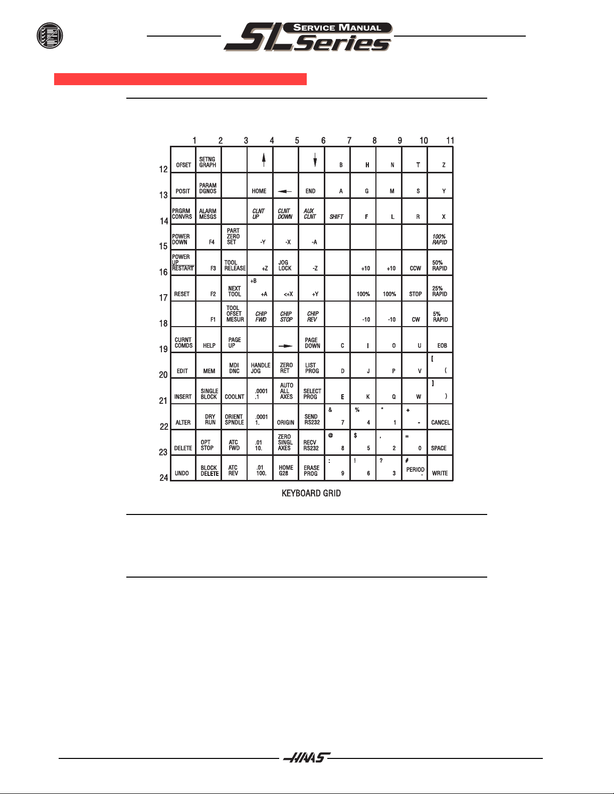
KEYBOARD DIAGNOSTIC
June 2001
NOTE: Refer to the "Cable Locations" section of this manual for a drawing of the
Keyboard Interface PCB.
28
NOTE: This Keyboard Grid is for machines with a Keyboard Interface only. This
Keyboard Grid is not for machines with a Serial Keyboard Interface.
The following is an example of how to troubleshoot the keypad:
NOTE: Keypad Diodes 1-24 correspond to chart numbers 1-24.
96-8710 rev C
Page 30

June 2001
TROUBLESHOOTING
Example
1. Pressing the RESET button will cause diodes 1 and 17 to conduct.
With the POWER OFF read across diode 1.
A typical reading is between .400-.700 ohms, note your reading.
2. Press and hold the RESET button. If the diode is conducting, the reading should drop about .03 ohms.
(If your reading was .486 and it dropped to .460, for a difference of .026; the diode is
good).
The same will hold true for diode 17 in this example. If the reading stays the same or there
is no change, the diode is not conducting. Pull P2 and read between pins 1 and 17.
Press and hold <RESET>. The meter should read a short (0 ohms) if not the keypad is
bad.
ETHERNET
Error 53 The computer name specified in the network path cannot be located
This error usually happens when NET USE C: \\SERVER\HAAS/PERSISTENT: NO /YES is entered during the
setup phase.
To fix this error first verify the following:
1. A 10 Base-T network is present.
2. The network cable is coming from a hub (not the server).
3. The server name that you specified in yo
2. u NET USE command is correct.
4. Your network is running IPX/SPX protocol.
If all of the above is correct and communications between the Haas CNC and the network are not established,
there may be compatibility issues between an older Novell network and an NT 4.0 server. If the NWLink IPX/
SPX Compatible Transport on the NT server is set to auto detect the protocols frame, the NT server may be
detecting the Novell server first and setting the NWLink IPX/SPX Compatible Transport frame protocol to 802.3
The NWLink IPX/SPX Compatible Transport required for the mills to connect to an NT server is 802.2. Since
these two frame protocols are different the mill would never connect to the desired NT server. To remedy this
check the following:
1. On the Ethernet boot disk, edit the protocol.ini file in the NETI directory.
2. Find the line FRAME=ETHERNET_802.2 and change it to FRAME=ETHERNET_802.3
3. Save the file
4. Insert the boot disk back into the CNC and cycle the power.
96-8710 rev C
29
Page 31

TROUBLESHOOTING
If an Error 53 is still present, restore the protocol.ini file to its previous state and do the following to the NT
server:
1. Open the control panel
2. Double click on the Network icon
3. Select the Protocols tab.
4. Highlight NWLINK IPX/SPX Compatible Transport.
5. Select properties.
6. Select Manual Frame Type Detection.
7. Click on Add.
8. Select Ethernet 802.2
9. Click on Add.
10. Click OK.
11. Close all windows and reboot the NT server.
Once the NT server is rebooted the NWLINK IPX/SPX Compatible Transport Frames is set to 802.2 and the mill
will be able to see the desired server.
Mill code will not work
June 2001
Make sure the command in the server routes back to the mill.
30
96-8710 rev C
Page 32

June 2001
TROUBLESHOOTING
1.8 BARFEEDER TROUBLESH OOTING
Push finger works but the pushrod will not load (during initial installation), ensure there are relays installed in
the top two tool changer locations on the IOPCB. (K9 and K10). This can occur when installing a barfeeder on
an older machine.
Problem with accuracy or incorrect pushes: Try doing a new set up as G105 Q2, Q4 or Q5 may have inadvertently been changed. Once the barfeeder is installed and running the set up procedures should not have to be
repeated unless the bar feeder is moved or the the collet or chuck is is changed.
The End of Bar switch at the right of the transfer tray has a switch paddle that can stick in the down position.
This will cause erroneous bar lengths and other problems. The switch paddle can be formed slightly to assure
clearance in the opening in the transfer tray.
There is a small ampount of play in between the ball screw and the ball nut. This can set up a small amount of
vibration when very fast spindle speeds are used. This is normal operation and will not affect finished part.
Any time the transport assembly on the bar feeder is disassembled or changed, parameters 240, 1st Aux Max
Travel, and 244, 1st Aux Min Travel, may be affected. If these parameters are not correctly set, malfunctioning
of the pushrod can occur and in some instances the barfeeder can crash. These parameters can be checked
by the following procedure:
1. Zero the bar feeder.
2. In handle jog mode, jog in the minus direction, until the V position on the screen
matches parameter 244.
3. Push down on the control arm positioner on the right side of the pushrod to ensure the rotation
control arm moves smoothly in and out of the notch on the left end. Loosen the two screws on the
fork activator and adjust if necessary.
4. On the left end of the pushrod control arm is a pin that drops onto a notch when the pushrod is
loaded. This pin shopuld be just far enough to the left to clear the lobe in the notch. If this pin is
not in the correct position, use the jog handle to adjust it and enter the new number from the
screen into parameter 244.
5. To adjust parameter 240 ensure the pushrod is unloaded and jog the push finger all the way to the
right. Paramter 240 should be set such that the carriage comes within about 3/8 of the ball screw
support end without hitting it. If not, adjust it using the jog handle and enter the V position from the
CRT into parameter 240.
96-8710 rev C
31
Page 33

ALARMS
2. ALARMS
Any time an alarm is present, the lower right hand corner of the screen will have a blinking "ALARM". Push the
ALARM display key to view the current alarm. All alarms are displayed with a reference number and a complete description. If the RESET key is pressed, one alarm will be removed from the list of alarms. If there are
more than 18 alarms, only the last 18 are displayed and the RESET must be used to see the rest. The presence of any alarm will prevent the operator from starting a program.
The ALARMS DISPLAY can be selected at any time by pressing the ALARM MESGS button. When there are
no alarms, the display will show NO ALARM. If there are any alarms, they will be listed with the most recent
alarm at the bottom of the list. The CURSOR and PAGE UP and PAGE DOWN buttons can be used to move
through a large number of alarms. The CURSOR right and left buttons can be used to turn on and off the
ALARM history display.
Note that tool changer alarms can be easily corrected by first correcting any mechanical problem, pressing
RESET until the alarms are clear, selecting ZERO RET mode, and selecting AUTO ALL AXES. Some messages are displayed while editing to tell the operator what is wrong but these are not alarms. See the editing
topic for those errors.
The following alarm list shows the alarm numbers, the text displayed along with the alarm, and a detailed
description of the alarm, what can cause it, when it can happen, and how to correct it.
June 2001
Alarm number and text: Possible causes:
101 MOCON Comm. Failure During a self-test of communications between the MOCON and main
processor, the main processor does not respond, and is suspected
to be dead. Check cable connections and grounding.
102 Servos Off Indicates that the servo motors are off, the tool changer is disabled,
the coolant pump is off, and the spindle motor is stopped. Caused by
EMERGENCY STOP, motor faults, tool changer problems, or power
fail.
103 X Servo Error Too Large Too much load or speed on X-axis motor. The difference between the
motor position and the commanded position has exceeded a
parameter. The motor may also be stalled, disconnected, or the
driver failed. The servos will be turned off and a RESET must be
done to restart. This alarm can be caused by problems with the
driver, motor, or the slide being run into the mechanical stops.
104 Y Servo Error Too Large Same as alarm 103.
105 Z Servo Error Too Large Same as alarm 103.
106 A Servo Error Too Large Same as alarm 103.
32
96-8710 rev C
Page 34

June 2001
107 Emergency Off EMERGENCY STOP button was pressed. Servos are also turned
off. After the E-STOP is released, the RESET button must be
pressed at least twice to correct this; once to clear the E-STOP
alarm and once to clear the Servos Off alarm.
108 X Servo Overload Excessive load on X-axis motor. This can occur if the load on the
motor over a period of several seconds or even minutes is large
enough to exceed the continuous rating of the motor. The servos
will be turned off when this occurs. This can be caused by running
into the mechanical stops but not much past them. It can also be
caused by anything that causes a very high load on the motors.
109 Y Servo Overload Same as alarm 108.
110 Z Servo Overload Same as alarm 108.
111 A Servo Overload Same as alarm 108.
112 No Interrupt Electronics fault. Call your dealer.
113 Turret Unlock Fault The turret took longer to unlock and come to rotation position than
allowed for in Parameter 62. The value in Parameter 62 is in
milliseconds. This may occur if the air pressure is too low, the tool
turret clamp switch is faulty or needs adjustment, or there is a
mechanical problem.
ALARMS
114 Turret Lock Fault The turret took longer to lock and seat than allowed for in Parameter
63. The value in Parameter 63 is in milliseconds. This may occur if
the air pressure is too low, the tool turret clamp switch is faulty or
needs adjustment, or there is a mechanical problem.
115 Turret Rotate Fault Tool motor not in position. During a tool changer operation the tool
turret failed to start moving or failed to stop at the right position.
Parameters 62 and 63 can adjust the time-out times. This alarm can
be caused by anything that jams the rotation of the turret. A loss of
power to the tool changer can also cause this, so check CB5 and
relays 1-8, 2-3, and 2-4.
116 Spindle Orientation Fault Spindle did not orient correctly. During a spindle orientation function,
the spindle is rotated until the lock pin drops in; but the lock pin never
dropped. Parameters 66, 70, 73, and 74 can adjust the time-out
times. This can be caused by a trip of circuit breaker CB4, a lack of
air pressure, or too much friction with the orientation pin.
117 Spindle High Gear Fault Gearbox did not shift into high gear. During a change to high gear, the
high gear sensor was not detected in time. Parameters 67, 70 and
75 can adjust the time-out times. Check circuit breaker CB4, the
circuit breaker for the air pressure solenoids and the spindle drive.
96-8710 rev C
33
Page 35

ALARMS
118 Spindle Low Gear Fault Gearbox did not shift into low gear. During a change to low gear, the
low gear sensor was not detected in time. Parameters 67, 70 and 75
can adjust the time-out times. Check the solenoids circuit breaker
CB4, and the spindle drive.
119 Over Voltage Incoming line voltage is above maximum. The tool changer, and
coolant pump will stop. If this condition persists, an automatic
shutdown will begin after the interval specified by parameter 296.
120 Low Air Pressure Air pressure dropped below 80 PSI for a period of time defined by
Parameter 76. Check your incoming air pressure for at least 100 PSI
and ensure that the regulator is set at 85 PSI.
121 Low Lub or Low Pressure Way lube is low or empty or there is no lube pressure or too high a
pressure. Check tank at rear of machine and below control cabinet.
Also check connector on the side of the control cabinet. Check that
the lube lines are not blocked.
122 Regen Overheat The regenerative load temperature is above a safe limit. This alarm
will turn off the spindle drive, coolant pump, and tool changer. One
common cause of this overheat condition is an input line voltage too
high. If this condition persists, an automatic shutdown will begin
after the interval specified by parameter 297. It can also be caused
by a high start/stop duty cycle of the spindle.
June 2001
123 Spindle Drive Fault Overheat or failure of spindle drive or motor. The exact cause is
indicated in the LED window of the spindle drive inside the control
cabinet. This can be caused by a stalled motor, shorted motor,
overvoltage, undervoltage, overcurrent, overheat of motor, or drive
failure.
124 Low Battery Memory batteries need replacing within 30 days. This alarm is only
generated at power on and indicates that the 3.3 volt Lithium battery
is below 2.5 volts. If this is not corrected within about 30 days, you
may lose your stored programs, parameters, offsets, and settings.
125 Tool Turret Fault Turret has not seated itself properly. There may be something
obstructing the turret between the housing and the turret itself.
126 Gear Fault GGearshifter is out of position when a command is given to start a
program or rotate the spindle. This means that the two speed gear
box is not in either high or low gear but is somewhere in between.
Check the air pressure, the solenoids circuit breaker CB4, and the
spindle drive. Use the POWER UP/RESTART button to correct the
problem.
127 Door Fault The control failed to detect a low signal at the Door Switch input after
the door was commanded and the Door Switch input was not
received after the door was commanded to close and the time set in
parameter #251 has elapsed.
34
96-8710 rev C
Page 36

June 2001
129 M Fin Fault M-Fin was active at power on. Check the wiring to your M code
interfaces. This test is only performed at power-on.
130 Chuck Unclamped The control detected that the chuck is unclamped. This is a possible
fault in the air solenoids, relays on the I/O Assembly, or wiring.
131 Tool Not Clamped When clamping or powering up the machine, the Tool Release
Piston is not Home. This is a possible fault in the air solenoids,
relays on the I/O Assembly, the drawbar assembly, or wiring.
132 Power Down Failure Machine did not turn off when an automatic power-down was com-
manded. Check wiring to POWIF card on power supply assembly,
relays on the IO assembly, and the main contactor K1.
133 Spindle Brake Engaged The brake is engaged. It must be released before the spindle can
turn.
134 Low Hydraulic Hydraulic pressure is sensed to be low. Check pump pressure
and Pressure hydraulic tank oil level. Verify proper pump and
machine phasing.
ALARMS
135 X Motor Over Heat Servo motor overheat. The temperature sensor in the motor indicates
over 150 degrees F. This can be caused by an extended overload of
the motor such as leaving the slide at the stops for several minutes.
136 Y Motor Over Heat Same as alarm 135.
137 Z Motor Over Heat Same as alarm 135.
138 A Motor Over Heat Same as alarm 135.
139 X Motor Z Fault Encoder marker pulse count failure. This alarm usually indicates that
the encoder has been damaged and encoder position data is
unreliable. This can also be caused by loose connectors at P1-P4.
140 Y Motor Z Fault Same as alarm 139.
141 Z Motor Z Fault Same as alarm 139.
142 A Motor Z Fault Same as alarm 139.
143 Spindle Not Locked Shot pin not fully engaged when a tool change operation is being per
formed. Check air pressure and solenoid circuit breaker CB4. This
can also be caused by a fault in the sense switch that detects the
position of the lock pin.
96-8710 rev C
144 Time-out-Call Your Dealer Time allocated for use prior to payment exceeded. Call your dealer.
35
Page 37

ALARMS
145 X Limit Switch Axis hit limit switch or switch disconnected. This is not normally
possible as the stored stroke limits will stop the slides before they
hit the limit switches. Check the wiring to the limit switches and
connector P5 at the side of the main cabinet. Can also be caused by
a loose encoder shaft at the back of the motor or coupling of motor to
the screw.
146 Y Limit Switch Same as alarm 145.
147 Z Limit Switch Same as alarm 145.
148 A Limit Switch Normally disabled for rotary axis.
149 Spindle Turning Spindle not at zero speed for tool change. A signal from the spindle
drive indicating that the spindle drive is stopped is not present while
a tool change operation is going on.
150 I Mode Out Of Range Internal software error; call your dealer.
151 Low TSC
June 2001
152 Self Test Fail Control has detected an electronics fault. All motors and solenoids
are shut down. This is most likely caused by a fault of the processor
board stack at the top left of the control. Call your dealer.
153 X-axis Z Ch Missing Broken wires or encoder contamination. All servos are turned off.
This can also be caused by loose connectors at P1-P4.
154 Y-axis Z Ch Missing Same as alarm 153.
155 Z-axis Z Ch Missing Same as alarm 153.
156 A-axis Z Ch Missing Same as alarm 153.
157 MOCON Watchdog Fault The self-test of the MOCON has failed. Replace the MOCON.
158 Video/Keyboard PCB Failure Internal circuit board problem. The VIDEO PCB in the processor
stack is tested at power-on. This could also be caused by a short
in the front panel membrane keypad. Call your dealer.
159 Keyboard Failure Keyboard shorted or button pressed at power on. A power-on test of
the membrane keypad has found a shorted button. It can also be
caused by a short in the cable from the main cabinet or by holding a
switch down during power-on.
160 Low Voltage The line voltage to control is too low. This alarm occurs when the AC
line voltage drops below 190 when wired for 230 volts or drops below
165 when wired for 208 volts.
36
96-8710 rev C
Page 38

June 2001
161 X-Axis Drive Fault Current in X servo motor beyond limit. Possibly caused by a stalled or
overloaded motor. The servos are turned off. This can be caused by
running a short distance into a mechanical stop. It can also be
caused by a short in the motor or a short of one motor leads to
ground.
162 Y-Axis Drive Fault Same as alarm 161.
163 Z-Axis Drive Fault Same as alarm 161.
164 A-Axis Drive Fault Same as alarm 161.
165 X Zero Ret Margin Too Small This alarm will occur if the home/limit switches move or are
misadjusted. This alarm indicates that the zero return position may
not be consistent from one zero return to the next. The encoder Z
channel signal must occur between 1/8 and 7/8 revolution of where
the home switch releases. This will not turn the servos off but will
stop the zero return operation.
166 Y Zero Ret Margin Too Small Same as alarm 165.
ALARMS
167 Z Zero Ret Margin Too Small Same as alarm 165.
168 A Zero Ret Margin Too Small Not normally enabled for A-axis.
169 Spindle Direction Fault Problem with rigid tapping hardware. The spindle started turning in
the wrong direction.
170 Phase Loss Problem with incoming line voltage between legs L1 and L2. This
usually indicates that there was a transient loss of input power to the
machine.
171 Rpm Too High To Unclamp The spindle speed exceeded the max speed allowed in parameter
248 to unclamp.
173 Spindle Ref Signal Missing The Z channel pulse from the spindle encoder is missing for hard
tapping synchronization.
174 Tool Load Exceeded The tool load monitor option is selected and the maximum load for a
tool was exceeded in a feed. This alarm can only occur if the tool load
monitor function is installed in your machine.
175 Ground Fault Detected A ground fault condition was detected in the 115V AC supply. This can
be caused by a short to ground in any of the servo motors, the tool
change motors, the fans, or the oil pump.
96-8710 rev C
176 Overheat Shutdown An overheat condition persisted longer than the interval specified by
parameter 297 and caused an automatic shutdown.
37
Page 39

ALARMS
177 Over Voltage Shutdown An overvoltage condition persisted longer than the interval specified
by parameter 296 and caused an automatic shutdown.
178 Divide by Zero Software error, or parameters are incorrect. Call your dealer.
179 Low Trans Oil Pressure
181 Macro not completed-spindle disabled Macro code operating Haas optional equipment (bar feeder, etc.) was
not completed for some reason (ESTOP, RESET, Power Down, etc.).
Check optional equipment and run recovery procedure.
182 X Cable Fault Cable from X-axis encoder does not have valid differential signals.
183 Y Cable Fault Same as alarm 182.
184 Z Cable Fault Same as alarm 82.
185 A Cable Fault Same as alarm 182.
June 2001
186 Spindle Not Turning Trying to feed while spindle is in the stopped position.
187 B Servo Error Too Large Same as alarm 103.
188 B Servo Overload Same as alarm 108.
189 B Motor Overheat Same as alarm 135.
190 B Motor Z Fault Same as alarm 139.
191 B Limit Switch Same as alarm 145.
192 B Axis Z Ch Missing Same as alarm 153.
193 B Axis Drive Fault Same as alarm 161.
194 B Zero Ret Margin Too Small Same as alarm 165.
195 B Cable Fault Same as 182.
197 100 Hours Unpaid Bill Call your dealer.
198 Spindle Stalled Control senses that no spindle fault has occurred, the spindle is at
speed, yet the spindle is not turning. Possibly the belt between the
spindle drive motor and spindle has slipped or is broken.
199 Negative RPM Internal software error; call your dealer.
38
96-8710 rev C
Page 40

June 2001
201 Parameter CRC Error Parameters lost maybe by low battery. Check for a low battery and
low battery alarm.
202 Setting CRC Error Settings lost maybe by low battery. Check for a low battery and low
battery alarm.
203 Lead Screw CRC Error Lead screw compensation tables lost maybe by low battery. Check
for CRC Error low battery and low battery alarm.
204 Offset CRC Error Offsets lost maybe by low battery. Check for a low battery and low
battery alarm.
205 Programs CRC Error Users program lost maybe by low battery. Check for a low battery and
low battery alarm.
206 Internal Program Error Possible corrupted program. Save all programs to disk, delete all,
then reload. Check for a low battery and low battery alarm.
207 Queue Advance Error Software Error; Call your dealer.
ALARMS
208 Queue Allocation Error Software Error; Call your dealer.
209 Queue Cutter Comp Error Software Error; Call your dealer.
210 Insufficient Memory Not enough memory to store users program. Check the space
available in the LIST PROG mode and possibly delete some programs.
211 Odd Prog Block Possible corrupted program. Save all programs to disk, delete all,
then reload.
212 Program Integrity Error Possible corrupted program. Save all programs to disk, delete all,
then reload. Check for a low battery and low battery alarm.
213 Program RAM CRC Error Electronics fault; Call your dealer.
214 No. of Programs Changed Indicates that the number of programs disagrees with the internal
variable that keeps count of the loaded programs. Call your dealer.
215 Free Memory PTR Changed Indicates the amount of memory used by the programs counted in
the system disagrees with the variable that points to free memory.
Call your dealer.
96-8710 rev C
216 Probe Arm Down While Running Indicates that the probe arm was pulled down while a program was
running.
217 X Axis Phasing Error Error occurred in phasing initialization of brushless motor. This can
be caused by a bad encoder, or a cabling error.
39
Page 41

ALARMS
218 Y Axis Phasing Error Same as alarm 217.
219 Z Axis Phasing Error Same as alarm 217.
220 A Axis Phasing Error Same as alarm 217.
221 B Axis Phasing Error Same as alarm 217.
222 C Axis Phasing Error Same as alarm 217.
223 Door Lock Failure In machines equipped with safety interlocks, this alarm occurs when
the control senses the door is open but it is locked. Check the door
lock circuit.
224 X Transition Fault Illegal transition of count pulses in X axis. This alarm usually
indicates that the encoder has been damaged and encoder position
data is unreliable. This can also be caused by loose connectors at
the MOCON and MOTIF PCB.
225 Y Transition Fault Same as alarm 224.
June 2001
226 Z Transition Fault Same as alarm 224.
227 A Transition Fault Same as alarm 224.
228 B Transition Fault Same as alarm 224.
229 C Transition Fault Same as alarm 224.
231 Jog Handle Transition Fault Illegal transition of count pulses in jog handle encoder. This alarm
usually indicates that the encoder has been damaged and encoder
position data is unreliable. This can also be caused by loose
connectors.
232 Spindle Transition Fault Illegal transition of count pulses in spindle encoder. This alarm
usually indicates that the encoder has been damaged and encoder
position data is unreliable. This can also be caused by loose
connectors at the MOCON.
233 Jog Handle Cable Fault Cable from jog handle encoder does not have valid differential
signals.
234 Spindle Enc. Cable Fault Cable from spindle encoder does not have valid differential signals.
235 Spindle Z Fault Same as alarm 139.
236 Spindle Motor Overload This alarm is generated in machines equipped with a Haas vector
drive, if the spindle motor becomes overloaded.
40
96-8710 rev C
Page 42

June 2001
237 Spindle Following Error The error between the commanded spindle speed and the actual
speed has exceeded the maximum allowable (as set in Parameter
184).
240 Empty Prog or No EOB DNC program not found, or no end of program found.
241 Invalid Code RS-232 load bad. Data was stored as comment. Check the program
being received.
242 No End Check input file for a number that has too many digits.
243 Bad Number Data entered is not a number.
244 Missing ) Comment must end with a " ) ".
245 Unknown Code Check input line or data from RS-232. This alarm can occur while
editing data into a program or loading from RS-232.
246 String Too Long Input line is too long. The data entry line must be shortened.
ALARMS
247 Cursor Data Base Error Software Error; Call your dealer.
248 Number Range Error Number entry is out of range.
249 Prog Data Begins Odd Possible corrupted program. Save all programs to disk, delete all,
then reload.
250 Program Data Error Same as alarm 249.
251 Prog Data Struct Error Same as alarm 249.
252 Memory Overflow Same as alarm 249.
253 Electronics Overheat This alarm is generated if the control cabinet temperature exceeds
135°F. This can be caused by an electronics problem, high room
temperature, or clogged air filter.
254 Spindle Motor Overheat Motor driving spindle is too hot. This alarm is only generated in
machines with a Haas vector drive. The spindle motor temperature
sensor sensed a high temperature for greater than 1.5 seconds.
257 Program Data Error Same as alarm 249.
96-8710 rev C
258 Invalid DPRNT Format Macro DPRNT statement not structured properly.
259 Bad Language Version Call your dealer.
260 Bad Language CRC Indicates FLASH memory has been corrupted or damaged.
41
Page 43

ALARMS
June 2001
261 Rotary CRC Error Rotary table saved parameters (used by Settings 30, 78) have a CRC
error.
262 Parameter CRC Missing RS-232 or disk read of parameter had no CRC when loading from
disk or RS-232.
263 Lead Screw CRC Missing Lead screw compensation tables have no CRC when loading from
disk or RS-232.
264 Rotary CRC Missing Rotary table parameters have no CRC when loading from disk or RS-
232.
265 Macro Variable File CRC Error Macro variables lost maybe by low battery. Check for a low battery
and low battery alarm. Reload the macro variable file.
268 DOOR OPEN @ M95 START Generated whenever an M95 (Sleep Mode) is encountered and the
door is open. The door must be closed in order to start sleep mode.
270 C Servo Error Too Large Same as alarm 103.
271 C Servo Overload Same as alarm 108.
272 C Motor Overheat Same as alarm 135.
273 C Motor Z Fault Same as alarm 139.
274 C Limit Switch Same as alarm 145.
275 C Axis Z Ch Missing Same as alarm 153.
276 C Axis Drive Fault Same as alarm 161.
277 C Zero Ret Margin Too Small Same as alarm 165.
278 C Cable Fault Same as alarm 182.
292 Mismatch Axis with I, K Chamfering I, (K) was commanded as X axis (Z axis) in the block with chamfering.
293 Invalid I,K or R in G01 The move distance in the block commanded with chamfering, corner
R is less than the chamfering, corner R amount.
294 Not G01 after The command after the block commanded with chamfering, corner R
is not Chamfering, Corner R G01.
295 Invalid Move After Chamfering The command after the block commanded with chamfering, corner R
is either missing or wrong. There must be a move perpendicular to
that of the chamfering block.
42
96-8710 rev C
Page 44

June 2001
296 Not One Axis Move Consecutive blocks commanded with chamfering, corner R (i.e., G01
Xb Kk; with Chamfering G01 Zb Ii). After each chamfering block,
there must be a single move perpendicular to the one with chamfering, corner R amount.
302 Invalid R in G02 or G03 Check your geometry. R must be greater than or equal to half the
distance from start to end.
303 Invalid X, B, or Z in G02 or G03 Check your geometry.
304 Invalid I, J, or K in G02 or G03 Check your geometry. Radius at start must match radius at end of arc
within 0.001 inches (0.01 mm.)
305 Invalid Q in Canned Cycle Q in a canned cycle must be greater than zero and must be a valid N
number.
306 Invalid I, J, K, or Q in Canned Cycle I, J, K, and Q in a canned cycle must be greater than zero.
307 Subroutine Nesting Too Deep Subprogram nesting is limited to nine levels. Simplify your program.
ALARMS
308 Invalid Tool Offset A tool offset not within the range of the control was used.
309 Exceeded Max Feed Rate Use a lower feed rate.
310 Invalid G Code G code not defined and is not a macro call.
311 Unknown Code Possible corruption of memory by low battery. Call your dealer.
312 Program End End of subroutine reached before M99. Need an M99 to return from
sub-routine.
313 No P Code In M97, M98, or G65 Must put subprogram number in P code.
314 Subprogram or Macro Not In Memory Check that a subroutine is in memory or that a macro is defined.
315 Invalid P Code In M97, M98 or M99 The P code must be the name of a program stored in memory
without a decimal point for M98 and must be a valid N number for
M99, G70, 71, 72, and 73.
316 X Over Travel Range X-axis will exceed stored stroke limits. This is a parameter in
negative direction and is machine zero in the positive direction. This
will only occur during the operation of a user's program.
96-8710 rev C
317 Y Over Travel Range Same as alarm 316.
318 Z Over Travel Range Same as alarm 316.
319 A Over Travel Range Not normally possible with A-axis.
43
Page 45

ALARMS
June 2001
320 No Feed Rate Specified Must have a valid F code for interpolation functions.
321 Auto Off Alarm Occurs in debug mode only.
322 Sub Prog Without M99 Add an M99 code to the end of program called as a subroutine.
324 Delay Time Range Error P code in G04 is greater than or equal to 1000 seconds (over 999999
milliseconds).
325 Queue Full Control problem; call your dealer.
326 G04 Without P Code Put a Pn.n for seconds or a Pn for milliseconds.
327 No Loop For M Code Except M97, M98 L code not used here. Remove L Code.
328 Invalid Tool Number Tool number must be between 1 and the value in Parameter 65.
329 Undefined M Code That M code is not defined and is not a macro call.
330 Undefined Macro Call Macro name O90nn not in memory. A macro call definition is in
parameters and was accessed by user program but that macro was
not loaded into memory.
331 Range Error Number too large.
332 H and T Not Matched This alarm is generated when Setting 15 is turned ON and an H code
number in a running program does not match the tool number in the
spindle. Correct the Hn codes, select the right tool, or turn off Setting
15.
333 X-Axis Disabled Parameters have disabled this axis. Not normally possible.
334 Y-Axis Disabled Same as alarm 333.
335 Z-Axis Disabled Same as alarm 333.
336 A-Axis Disabled An attempt was made to program the A-axis while it was disabled
(DISABLED bit in Parameter 43 set to 1).
337 GOTO or P line Not Found Subprogram is not in memory, or P code is incorrect. P not found
338 Invalid IJK and XYZ in G02 or G03 There is a problem with circle definition; check your geometry.
339 Multiple Codes Only one M, X, Y, Z, A , Q, etc. allowed in any block or two G codes in
the same group. Two or more I,K, R are commanded in the same
block with chamfering, corner rounding
44
96-8710 rev C
Page 46

June 2001
340 Cutter Comp Begin With G02 or G03 Select cutter compensation earlier. Cutter comp. must begin on a
linear move.
341 Cutter Comp End With G02 or G03 Disable cutter comp later.
342 Cutter Comp Path Too Small Geometry not possible. Check your geometry.
343 Display Queue Record Full A block exists that is too long for displaying queue. Shorten title block.
344 Cutter Comp With G18 and G19 Cutter comp only allowed in XY plane (G17).
345 Invalid R Value in M19 or G105 R value must be positive.
346 Illegal M Code There was an M85 or M86 commanded. These commands are not
allowed while Setting 51 DOOR HOLD OVERRIDE is OFF.
348 Illegal Spiral Motion Linear axis path is too long. For helical motions, the linear path must
not be more than the length of the circular component.
ALARMS
349 Prog Stop W/O Cancel Cutter Comp Cutter compensation has been cancelled without an exit move.
Potential damage to part.
350 Cutter Comp Look Ahead Error There are too many non-movement blocks between motions when
cutter comp is being used. Remove some intervening blocks.
351 Invalid P Code In a block with G103 (Block Lookahead Limit), a value between 0 and
15 must be used for the P code.
352 Aux Axis Power Off Aux B, C, U, V, or W axis indicate servo off. Check auxiliary axes.
Status from control was OFF.
353 Aux Axis No Home A ZERO RET has not been done yet on the aux axes. Check auxiliary
axes. Status from control was LOSS.
354 Aux Axis Disconnected Aux axes not responding. Check auxiliary axes and RS-232 connec-
tions.
355 Aux Axis Position Mismatch Mismatch between machine and aux axes position. Check aux axes
and interfaces. Make sure no manual inputs occur to aux axes.
356 Aux Axis Travel Limit Aux axes are attempting to travel past their limits.
96-8710 rev C
357 Aux Axis Disabled Aux axes are disabled.
358 Multiple Aux Axis Can only move one auxiliary axis at a time.
359 Invalid I, J Or K In G12 Or G13 Check your geometry.
45
Page 47

ALARMS
360 Tool Changer Disabled Check Parameter 57. Not a normal condition for the Lathe.
361 Gear Change Disabled Not used.
362 Tool Usage Alarm Tool life limit was reached. To continue, reset the usage count in the
Current Commands display and press RESET.
363 Coolant Locked Off Override is off and program tried to turn on coolant.
364 No Circ Interp Aux Axis Only rapid or feed is allowed with aux axes.
366 Cutter Comp Interference G01 cannot be done with tool size.
367 Cutter Comp Interference G01 cannot be done with tool size.
368 Groove Too Small Tool too big to enter cut.
369 Tool Too Big Use a smaller tool for cut.
June 2001
372 Tool Change in Canned Cycle Tool change not allowed while canned cycle is active.
373 Invalid Code in DNC A code found in a DNC program could not be interpreted because of
DNC restrictions.
374 Missing XBZA in G31 or G36 G31 skip function requires an X, B, Z, or A move.
376 No Cutter Comp In Skip Skip G31 function cannot be used with cutter compensation.
377 No Skip in Graph/Sim Graphics mode cannot simulate skip function.
378 Skip Signal Found Skip signal check code was included but skip was found when it was
not expected.
379 Skip Signal Not Found Skip signal check code was included but skip was not found when it
was expected.
380 X,B,A Or G49 Not Allowed In G37 G37 may only specify Z-axis and must have tool offset defined.
381 G43,G44 Not Allowed In G36 Or G136 Auto work offset probing must be done without tool offset.
382 D Code Required In G35 A Dnn code is required in G35 in order to store the measured tool
diameter.
383 Inch Is Not Selected G20 was specified but settings have selected metric input.
384 Metric Is Not Selected G21 was specified but settings have selected inches.
46
96-8710 rev C
Page 48

June 2001
385 Invalid L, P, or R Code in G10 G10 was used to changes offsets but L, P, or R code is missing or
invalid.
386 Invalid Address Format An address A..Z was used improperly.
387 Cutter Comp Not Allowed With G103 If block buffering has been limited, Cutter comp cannot be used
388 Cutter Comp Not Allowed With G10 Coordinates cannot be altered while cutter comp is active. Move G10
outside of cutter comp enablement.
389 G17, G18, G19 Illegal in G68 Planes of rotation cannot be changed while rotation is enabled.
390 No Spindle Speed S code has not been encountered. Add an S code.
391 Feature Disabled An attempt was made to use a control feature not enabled by a
parameter bit. Set the parameter bit to 1.
392 B Axis Disabled Same as alarm 333.
ALARMS
393 Invalid Motion in G84 or G184 Rigid Tapping can only be in the Z minus G74 or G84 direction.
Make sure that the distance from the initial position to the commanded Z depth is in the minus direction.
394 B Over Travel Range The tailstock (B-axis) has exceeded it's maximum range of travel.
395 Invalid Code in Canned Cycle Any canned cycle requiring a PQ path sequence may not have an M
code in the same block. That is G70, G71, G72, and G73.
396 Conflicting Axes An Incremental and Absolute command can not be used in the same
block of code. For example, X and U cannot be used in the same
block.
397 Invalid D Code In the context that the D code was used it had an invalid value. Was it
positive?
398 Aux Axis Servo Off Aux. axis servo shut off due to a fault.
399 Invalid U Code In the context that the U code was used it had an invalid value. Was it
positive?
403 RS-232 Too Many Progs Cannot have more than 200 programs in memory.
96-8710 rev C
404 RS-232 No Program Name Need name in programs when receiving ALL; otherwise has no way
to store them.
405 RS-232 Illegal Prog Name Check files being loaded. Program name must be Onnnnn and must
be at beginning of a block.
47
Page 49

ALARMS
406 RS-232 Missing Code A receive found bad data. Check your program. The program will be
stored but the bad data is turned into a comment.
407 RS-232 Invalid Code Check your program. The program will be stored but the bad data is
turned into a comment.
408 RS-232 Number Range Error Check your program. The program will be stored but the bad data is
turned into a comment.
409 RS-232 Invalid N Code Bad Parameter or Setting data. User was loading settings or param-
eters and something was wrong with the data.
410 RS-232 Invalid V Code Bad parameter or setting data. User was loading settings or param-
eters and something was wrong with the data.
411 RS-232 Empty Program Check your program. Between % and % there was no program found.
412 RS-232 Unexpected End of Input Check Your Program. An ASCII EOF code was found in the input data
before the complete program was completely received. This is a
decimal code 26.
June 2001
413 RS-232 Load Insufficient Memory Program received doesnt fit. Check the space available in the LIST
PROG mode and possibly delete some programs.
414 RS-232 Buffer Overflow Data sent too fast to CNC. This alarm is not normally possible as
this control can keep up with even 38400 bits per second.
415 RS-232 Overrun Data sent too fast to CNC. This alarm is not normally possible as
this control can keep up with as much as 38400 bits per second.
416 RS-232 Parity Error Data received by CNC has bad parity. Check parity settings, number
of data bits and speed. Also check your wiring.
417 RS-232 Framing Error Data received was garbled and proper framing bits were not found.
One or more characters of the data will be lost. Check parity settings,
number of data bits and speed.
418 RS-232 Break Break condition while receiving. The sending device set the line to a
break condition. This might also be caused by a simple break in the
cable.
419 Invalid Function For DNC A code found on input of a DNC program could not be interpreted.
420 Program Number Mismatch The O code in the program being loaded did not match the O code
entered at the keyboard. Warning only.
423 Servo Bar Eob Switch Position Unknown Place 12 inch standard bar in charging position and run G105 Q5 to
set End of Bar Switch Position.
48
96-8710 rev C
Page 50

June 2001
424 Servo Bar Metric Unsupported Metric mode is currently unsupported. Change setting (9) to inch.
425 Servo Bar Length Unknown Both the bar length and reference position are unknown. Unload bar,
Run G105 Q4 followed by G105 Q2 or Q3.
426 Servo Bar Illegal Code G105 (feed bar) commanded with an illegal code on block. Legal
codes are I,J,K,P,Q,R
428 Servo Bar Switch Failure One of the switches controlling the Servo Bar failed.
429 Disk Dir Insufficient Memory Disk memory was almost full when an attempt was made to read the
disk directory.
430 Disk Unexpected Check your program. An ASCII EOF code was found in the input data
End of Input before the complete program was received. This is a
decimal code 26.
431 Disk No Prog Need name in programs when receiving ALL; otherwise has no way
to store them.
ALARMS
432 Disk Illegal Prog Name Check files being loaded. Program must be Onnnnn and must be at
the beginning of a block.
433 Disk Empty Prog Name Check your program. Between % and % there was no program
found.
434 Disk Load Insufficient Memory Program received doesn't fit. Check the space available in the LIST
PROG mode and possibly delete some programs.
435 Disk Abort Could not read disk.
436 Disk File Not Found Could not find disk file.
437 TS Under Shoot The tailstock did not reach its intended destination point.
438 TS Moved While Holding Part The tailstock moved more than a preset amount while holding a part
(e.g., the part slips in the chuck).
439 TS Found No Part During an M21 or G01, the tailstock reached the hold point without
encountering the part.
440 Servo Bar Max Parts Reached Job Complete. Reset Current # Parts Run on Servo Bar current
commands page.
96-8710 rev C
441 Servo Bar Max Bars Reached Job Complete. Reset Current # Bars Run on Servo Bar current
commands page.
49
Page 51

ALARMS
442 Servo Bar Max Length Reached Job Complete. Reset Current Length Run on Servo Bar current
commands page.
443 Servo Bar Already Nested An Illegal G105 Pnnn was found in cutoff subprogram.
445 Servo Bar Fault SERVO BAR program error.
446 Servo Bar Bar Too Long The Bar that was just loaded is longer than the Length of Longest
Bar as displayed on the Servo Bar current commands page. The
system was unable to accurately measure it.
447 Servo Bar Bar In Way The end of bar switch was depressed and a load or unload bar was
commanded. Remove the bar.
448 Servo Bar Out Of Bars Add more Bars.
449 Servo Bar Cutter Comp Not Allowed G105 cannot be executed while cutter compensation is invoked.
450 Bar Feeder Fault This means that discrete input 1027 (BFSPLK) is too high. See
parameter 278 bit 20 CK BF status.
June 2001
451 Bar Feeder Spindle Interlock This means that discrete input 1030 (BF FLT) is high. See parameter
278 bit 21 CK BF SP ILK.
452 Servo Bar Gearmotor Timeout The motor which loads bars and the Push rod did not complete its
motion in the allowed time. Check for jammed bars.
453 C Axis Engaged A spindle command (M14, M41, M42, G05 or G77) was given with the
C axis drive engaged. The C axis motormust be disengaged with
M155 before a spindle brake or gear change.
454 C-Axis Not Engaged A command was given to the C-axis without the C-axis engaged. The
C-axis drive must be engaged with M154 before commanding the Caxis.
501 Too Many Assignments In One Block Only one assignment = is allowed per block. Divide block in error
into multiple blocks.
502 [ Or = Not First Term In Expressn An expression element was found where it was not preceded by [ or
=, that start expressions.
503 Illegal Macro Variable Reference A macro variable number was used that is not supported by this
control, use another variable.
504 Unbalanced Paren. In Expression Unbalanced brackets, [ or ], were found in an expression. Add or
delete a bracket.
505 Value Stack Error The macro expression value stack pointer is in error. Call your dealer.
50
96-8710 rev C
Page 52

June 2001
506 Operand Stack Error The macro expression operand stack pointer is in error. Call your
dealer.
507 Too Few Operands On Stack An expression operand found too few operands on the expression
stack. Call your dealer.
508 Division By Zero A division in a macro expression attempted to divide by zero. Re-
configure expression.
509 Illegal Macro Variable Use See "MACROS" section for valid variables.
510 Illegal Operator or Function Use See "MACROS" section for valid operators.
511 Unbalanced Right Brackets Number of right brackets not equal to the number of left brackets.
512 Illegal Assignment Use Attempted to write to a read-only macro variable.
513 Var. Ref. Not Allowed With N Or O Alphabetic addresses N and O cannot be combined with macro
variables. Do not declare N#1, etc.
ALARMS
514 Illegal Macro Address Reference A macro variable was used incorrectly with an alpha address. Same
as 513.
515 Too Many Conditionals In a Block Only one conditional expression is allowed in any WHILE or IF-THEN
block.
516 Illegal Conditional Or No Then A conditional expression was found outside of an IF-THEN, WHILE,
or M99 block.
517 Exprsn. Not Allowed With N Or O A macro expression cannot be concatenated to N or O. Do not
declare O[#1], etc.
518 Illegal Macro Exprsn Reference An alpha address with expression, such as A[#1+#2], evaluated
incorrectly. Same as 517.
519 Term Expected In the evaluation of a macro expression an operand was expected
and not found.
520 Operator Expected In the evaluation of a macro expression an operator was expected
and not found.
521 Illegal Functional Parameter An illegal value was passed to a function, such as SQRT[ or ASIN[.
96-8710 rev C
51
Page 53

ALARMS
522 Illegal Assignment Var Or Value A variable was referenced for writing. The variable referenced is read
only.
523 Conditional Reqd Prior To THEN THEN was encountered and a conditional statement was not
processed in the same block.
524 END Found With No Matching DO An END was encountered without encountering a previous matching
DO. DO-END numbers must agree.
525 Var. Ref. Illegal During Movement Variable cannot be read during axis movement.
526 Command Found On DO/END Line A G-code command was found on a WHILE-DO or END macro block.
Move the G-code to a separate block.
527 = Not Expected Or THEN Required Only one Assignment is allowed per block, or a THEN statement is
missing.
528 Parameter Precedes G65 On G65 lines all parameters must follow the G65 G-code. Place
parameters after G65.
June 2001
529 Illegal G65 Parameter The addresses G, L, N, O, and P cannot be used to pass param-
eters.
530 Too Many I, J, or Ks in G65 Only 10 occurrences of I, J, or K can occur in a G65 subroutine call.
Reduce the I, J, or K count.
531 Macro Nesting Too Deep Only four levels of macro nesting can occur. Reduce the amount of
nested G65 calls.
532 Unknown Code In Pocket Pattern Macro syntax is not allowed in a pocket pattern subroutine.
533 Macro Variable Undefined A conditional expression evaluated to an UNDEFINED value, i.e. #0.
Return True or False.
534 DO Or END Already In Use Multiple use of a DO that has not been closed by and END in the
same subroutine. Use another DO number.
535 Illegal DPRNT Statement A DPRNT statement has been formatted improperly, or DPRNT does
not begin block.
536 Command Found On DPRNT Line A G-code was included on a DPRNT block. Make two separate
blocks.
537 RS-232 Abort On DPRNT While a DPRNT statement was executing, the RS-232 communica-
tions failed.
538 Matching END Not A WHILE-DO statement does not contain a matching END statement.
Add the proper END statement.
52
96-8710 rev C
Page 54

June 2001
539 Illegal Goto Expression after GOTO not valid.
540 Macro Syntax Not Allowed A section of code was interpreted by the control where macro
statement syntax is not permitted. In lathe controls, PQ sequences
describing part geometry cannot use macro statements in the part
path description.
541 Macro Alarm This alarm was generated by a macro command in a program.
600 Code Not Expected In This Context During program interpretation, the control found code out of context.
This may indicate an invalid address code found in a PQ sequence.
It may also indicate faulty memory hardware or lost memory. Look at
the highlighted line for improper G-code.
601 Maximum PQ Blocks Exceeded The maximum number of blocks making up a PQ sequence was
exceeded. Currently, no more than 65535 blocks can be between P
and Q.
602 Non Monotonous PQ Blocks in X The path defined by PQ was not monotonic in the X axis. A monotonic
path is one which does not change direction starting from the first
motion block.
ALARMS
603 Non Monotonous PQ Blocks in Z The path defined by PQ was not monotonic in the Z axis. A monotonic
path is one which does not change direction starting from the first
motion block.
604 Non Monotonous Arc In PQ Block A non-monotonic arc was found in a PQ block. This will occur in PQ
blocks within a G71 or G72 if the arc changes it's X or Z direction.
Increasing the arc radius will often correct this problem.
605 Invalid Tool Nose Angle An invalid angle for the for the cutting tool tip was specified. This will
occur in a G76 block if the A address has a value that is not from 0 to
120 degrees.
606 Invalid A Code An invalid angle for linear interpolation was specified. This will occur
in a G01 block if the A address was congruent to 0 or 180 degrees.
607 Invalid W Code In the context that the W code was used it had an invalid value. Was
it positive?
96-8710 rev C
53
Page 55

ALARMS
609 Tailstock Restricted Zone This alarm is caused by an axis moving into the tailstock restricted
zone during program execution. To eliminate the problem, change
the program to avoid the restricted zone or change Setting 93 or
Setting 94 to adjust the restricted zone. To recover, go to jog mode,
press RESET twice to clear the alarm, then jog away from the
restricted zone.
610 G71/G72 Domain Nesting Exceeded The number of troughs nested has exceeded the control limit.
Currently, no more than 10 levels of trough can be nested. Refer to
the explanation of G71 for a description of trough nesting.
611 G71/G72 Type I Alarm When G71 or G72 is executing and the control detects a problem in
the defined PQ path. It is used to indicate which method of roughing
has been selected by the control. It is generated to help the programmer when debugging G71 or G72 commands.
The control often selects Type I roughing when the programmer has
intended to use Type II roughing. To select Type II, add R1 to the G71/
G72 command block (in YASNAC mode), or add a Z axis reference to
the P block (in FANUC mode).
612 G71/G72 Type II Alarm This alarm is similar to Alarm 611, but indicates that the control has
selected Type II roughing.
June 2001
613 Command Not Allowed In Cutter Comp. A command (M96, for example) in the highlighted block cannot be
executed while cutter comp. is invoked.
614 Invalid Q Code A Q address code used a numeric value that was incorrect in the
context used. Q used to reference tip codes in G10 can be 0...9. In
M96 Q can reference only bits 0 to 31. Use an appropriate value for Q
615 No Intersection to While cutter comp was in effect, a geometry was encountered whose
Offsets in CC compensated paths had no solution given the tool
offset used. This can occur when solving circular geometries.
Correct the geometry or change the tool radius.
616 Canned Cycle Using P & Q is Active A canned cycle using P & Q is already executing. A canned cycle can
not be executed by another PQ canned cycle.
617 Missing Address This alarm is generated if an address code is missing. This alarm
supports G77.
618 INVALID ADDRESS This alarm is generated if an address code is being used incorrectly.
For example, a negative value is being used for an address code that
should be positive.
619 Stroke Exceeds Start Position This alarm is generated by an incorrect G71 or G72 type 2 command.
It refers to a stroke in the PQ path of a G71 or G72 type 2 canned
cycle has passed the starting point. Try adjusting the starting point in
the block before the G71 or G72.
54
96-8710 rev C
Page 56

June 2001
620 C Axis Disabled Same as alarm 333.
621 C Over Travel Range Same as alarm 316.
623 Invalid Code In G112 Only G1, G2, G3 and G17 are allowed. G113 cancels G112. Axes X
and Y Cartesian coordinate are used for G1,G2, and G3.
629 Exceeded Max Feed Per Rev This alarm supports G77 and G5. If the alarm is received during a
G77, reduce diameter of part or change geometry. If the alarm is
received during a G5, reduce X or Z travel.
701 U Servo Error Too Large MOCON2 Same as alarm 103.
702 V Servo Error Too Large Mocon2 Same as alarm 103.
703 W Servo Error Too Large Mocon2 Same as alarm 103.
704 C Servo Error Too Large Mocon2 Same as alarm 103.
ALARMS
705 Tt Servo Error Too Large Mocon2 Same as alarm 103.
706 Ss Servo Error Too Large Mocon2 Same as alarm 103.
707 J Servo Error Too Large Mocon2 Same as alarm 103.
708 S Servo Error Too Large Mocon2 Same as alarm 103.
711 U Servo Overload Mocon2 Same as alarm 108.
712 V Servo Overload Mocon2 Same as alarm 108.
713 W Servo Overload Mocon2 Same as alarm 108.
714 A Servo Overload Mocon2 Same as alarm 108.
715 B Servo Overload Mocon2 Same as alarm 108.
716 C Servo Overload Mocon2 Same as alarm 108.
717 J Servo Overload Mocon2 Same as alarm 108.
96-8710 rev C
718 S Servo Overload Mocon2 Same as alarm 108.
721 U Motor Over Heat Mocon2 Same as alarm 135.
722 V Motor Over Heat Mocon2 Same as alarm 135.
55
Page 57

ALARMS
723 W Motor Over Heat Mocon2 Same as alarm 135.
724 A Motor Over Heat Mocon2 Same as alarm 135.
725 B Motor Over Heat Mocon2 Same as alarm 135.
726 C Motor Over Heat Mocon2 Same as alarm 135.
727 J Motor Over Heat Mocon2 Same as alarm 135.
728 S Motor Over Heat Mocon2 Same as alarm 135.
731 U Motor Z Fault Mocon2 Same as alarm 139.
732 V Motor Z Fault Mocon2 Same as alarm 139.
733 W Motor Z Fault Mocon2 Same as alarm 139.
734 A Motor Z Fault Mocon2 Same as alarm 139.
June 2001
735 B Motor Z Fault Mocon2 Same as alarm 139.
736 C Motor Z Fault Mocon2 Same as alarm 139.
737 J Motor Z Fault Mocon2 Same as alarm 139.
738 S Motor Z Fault Mocon2 Same as alarm 139.
741 U Axis Z Ch Missing Mocon2 Same as alarm 153.
742 V Axis Z Ch Missing Mocon2 Same as alarm 153.
743 W Axis Z Ch Missing Mocon2 Same as alarm 153.
744 A Axis Z Ch Missing Mocon2 Same as alarm 153.
745 B Axis Z Ch Missing Mocon2 Same as alarm 153.
746 C Axis Z Ch Missing Mocon2 Same as alarm 153.
747 J Axis Z Ch Missing Mocon2 Same as alarm 153.
748 S Axis Z Ch Missing Mocon2 Same as alarm 153.
751 U Axis Drive Fault Mocon2 Same as alarm 161.
56
96-8710 rev C
Page 58

June 2001
752 V Axis Drive Fault Mocon2 Same as alarm 161.
753 W Axis Drive Fault Mocon2 Same as alarm 161.
754 A Axis Drive Fault Mocon2 Same as alarm 161.
755 B Axis Drive Fault Mocon2 Same as alarm 161.
756 C Axis Drive Fault Mocon2 Same as alarm 161.
757 J Axis Drive Fault Mocon2 Same as alarm 161.
758 S Axis Drive Fault Mocon2 Same as alarm 161.
761 U Cable Fault Mocon2 Same as alarm 182.
762 V Cable Fault Mocon2 Same as alarm 182.
763 W Cable Fault Mocon2 Same as alarm 182.
ALARMS
764 A Cable Fault Mocon2 Same as alarm 182.
765 B Cable Fault Mocon2 Same as alarm 182.
766 C Cable Fault Mocon2 Same as alarm 182.
767 J Cable Fault Mocon2 Same as alarm 182.
768 S Cable Fault Mocon2 Same as alarm 182.
771 U Phasing Error Mocon2 Same as alarm 217.
772 V Phasing Error Mocon2 Same as alarm 217.
773 W Phasing Error Mocon2 Same as alarm 217.
774 A Phasing Error Mocon2 Same as alarm 217.
775 B Phasing Error Mocon2 Same as alarm 217.
776 C Phasing Error Mocon2 Same as alarm 217.
96-8710 rev C
777 J Phasing Error Mocon2 Same as alarm 217.
778 S Phasing Error Mocon2 Same as alarm 217.
57
Page 59

ALARMS
781 U Transition Fault Mocon2 Same as alarm 224.
782 V Transition Fault Mocon2 Same as alarm 224.
783 W Transition Fault Mocon2 Same as alarm 224.
784 A Transition Fault Mocon2 Same as alarm 224.
785 B Transition Fault Mocon2 Same as alarm 224.
786 C Transition Fault Mocon2 Same as alarm 224.
787 J Transition Fault Mocon2 Same as alarm 224.
788 S Transition Fault Mocon2 Same as alarm 224.
791 Comm. Failure With Mocon2 Same as alarm 101.
792 MOCON2 Watchdog Fault Same as alarm 157.
June 2001
796 Sub Spindle Not Turning Same as alarm 186.
797 Sub Spindle Orientation Fault Spindle did not orient correctly. During a spindle orientation function,
the spindle is rotated until the lock pin drops in; but the lock pin never
dropped. This can be caused by a trip of circuit breaker CB4, a lack
of air pressure, or too much friction with the orientation pin.
900 Manual Parameter Changes When the operator alters the value of a parameter, alarm 900 PAR
NO xxx HAS CHANGED. OLD VALUE WAS xxx. will be added to the
alarm history. When the alarm history is displayed, the operator will
be able to see the parameter number and the old value along with
the date and time the change was made. Note that this is not a resettable alarm, it is for information purposes only.
901 Parameter Changes Via Disk Load This is a new feature. When a parameter file has been loaded from
disk, alarm 901 PARAMETERS HAVE BEEN LOADED BY DISK will be
added to the alarm history along with the date and time. Note that
this alarm is not a re-settable alarm, it is for information purposes
only.
902 Parameter Changes Via RS-232 Load When a parameter file has been loaded via RS-232, alarm 902
PARAMETERS HAVE BEEN LOADED BY RS-232 will be added to the
alarm history along with the date and time. Note that this alarm is not
a re-settable alarm, it is for information purposes only.
903 Machine Power Up When the machine is powered up, alarm 903 CNC MACHINE
POWERED UP will be added to the alarm history along with the date
and time. Note that this alarm is not a re-settable alarm, it is for
information purposes only.
End Of List
NOTE: Alarms 1000-1999 are user defined.
58
96-8710 rev C
Page 60

June 2001
MECHANICAL SERVICE
3. MECHANICAL SERVICE
RECOMMENDED TORQUE VALUES FOR MACHINE FASTENERS
The following chart should be used as a reference guide for torquing machine fasteners where specified.
DIAMETER TORQUE
1/4 - 20 15 ft. lb.
5/16 - 18 30 ft. lb.
3/8 - 16 50 ft. lb.
M10 - 100 50 ft. lb.
M12 - 65 100 ft. lb.
1/2 - 13 80 ft. lb.
3/4 - 10 275 ft. lb.
1 - 8 450 ft. lb.
3.1 TURRET
TURRET CRA SH RECOVERY PROCEDURE
1. Change Setting 7, "Parameter Lock", to OFF. Move to Parameter 43 on the Parameters Display.
This is the tool turret motor parameters. Change INVIS AXIS from 1 to 0 (zero).
2. Move to the Alarm Display and type DEBUG and then press the WRITE key. Verify that the
debug line is displayed.
NOTE: Ensure there is adequate clearance between the turret and chuck before
performing the next step.
3. Press PRGRM/CNVRS, then the MDI key. Type M43 into MDI and press CYCLE START. This will
unlock the turret by pushing it in the Z-direction.
4. Press the HANDLE JOG key, and then the POSIT key to get into the Position Display and Jog
mode. The A axis should be displayed below the X and Z axes.
5. Press the letter "A", then "HANDLE JOG", and then a jog speed other than ".1". A message
should indicate that the A axis is being jogged.
6. Turn the JOG handle until the obstruction is cleared and the turret rotates freely. If an
OVERCURRENT alarm is received, press RESET and turn the JOG handle in the opposite direction.
96-8710 rev C
7. Move to Parameter 43 on the Parameter Display and change INVIS AXIS back to 1. Change
Setting 7 back to ON.
8. Turn the control power off and then back on. The turret can now be positioned by pressing either
POWER UP/RESTART or AUTO ALL AXES.
NOTE: If alarms 111 or 164 occur after the obstruction is cleared, you may need to
adjust the turret motor coupling.
59
Page 61

MECHANICAL SERVICE
IMPORTANT!!
After a crash the following procedures should be performed in order to verify proper turret
alignment.
1. Turret alignment verification (X-Axis)
2. Spindle alignment verification
3. Turret alignment verification (Spindle)
TURRET RE MOVAL AND REP LACEMENT
June 2001
21
19
20
Removal
23
24
22
25
28
29
30
31
32
33
26
27
26
37
38
34
43
42
26
41
1. Remove the sliding tool changer and turret assembly covers.
2. Change Parameter 76 from 500 to 50000 (so you will not trip
on a low air pressure alarm).
PARTS LIST
36
19 SHCS 5/16-18 x 1
35
20 Turret retaining cap
21 SHCS 7/16-14 x 2-1/4
22 Turret male coupling
23 Turret
24 SHCS 7/16-14 x 2-1/4
25 Female turret coupling
26 Thrust washer
27 Thust needle bearing
27
26
28 Shoulder bolt
29 Spring retainer
30 Die spring
31 Coupling mount
32 Coupling mount bushing
(bronze)
39
33 Turret cam
40
34 15/16 steel ball
35 HHB 5/16-18 x 1
36 Lever cam
37 Belleville spacer
38 Belleville washers
39 Key
40 Ring switch
41 Lock nut
42 Spur gear
43 Turret shaft
60
3. Remove the air line.
4. Put a 3/4" wrench on the bolt at the end of the air cycle. Pull down (-X) until the turret is fully
unclamped.
5. Place a block snugly between the back of the turret shaft and the casting to keep the turret shaft
from shifting.
CAUTION! If the shaft moves back when the turret is disconnected the ball
bearings in the turret cam may fall and have to be replaced before the
turret can be reassembled.
96-8710 rev C
Page 62

June 2001
MECHANICAL SERVICE
6. Remove the four bolts from the turret retainer and remove the retainer.
7. Remove the turret from the shaft.
8. The two washers, needle bearing, and key should be removed from the shaft and put aside at this
Installation
1. Put a small amount of grease on one side of the washers.
2. Place the washer on the surface of the turret and center it using your fingers. Be sure to keep
3. Put a small amount of grease on both sides of the second washer.
4. Place the washer on the spring retainer on the lip of the turret shaft. Clean any grease that may
NOTE: If a shaft extension is available install it at this time. Using the extension gives
you greater movement of the turret and allows you to remove and easily install
the key, washers and needle bearings
CAUTION! The turret is heavy and could be slippery.
time.
grease off the surface facing the needle bearing.
have gotten on the shaft.
5. Place the needle bearing on the lip and stick it to the washer. Be sure the other surface of the
bearing is clean and free of grease.
6. Put a small amount of grease on the turret key to hold it in place.
7. Place the turret on the shaft. (align the turret key)
NOTE: Check that the turret key did not fall off.
Check that the washer is centered on the turret.
Check that the washer and needle bearing are still on the shaft lip.
8. Slide the turret fully on the shaft.
9. Replace the turret retainer and snug the four bolts.
NOTE: Check the turret "O" ring. If you can see either the washer or the needle bearing
they have slid off the shaft. Return to step 7 of the turret removal section.
96-8710 rev C
61
Page 63

MECHANICAL SERVICE
10. Tighten the four turret retainer bolts.
11. Remove the brace from between the turret shaft and the casing.
12. Connect the air. The turret should clamp.
13. Change Parameter 76 back to 500.
14. Exercise the tool changer to verify proper operation.
15. Replace the turret assembly and sliding tool change covers.
June 2001
62
96-8710 rev C
Page 64

June 2001
MECHANICAL SERVICE
TURRET SHA FT REMOVAL AND REPLACEMENT
7
5
4
2
1
6
3
Turret Shaft Removal
14
13
12
10
8
9
11
15
16
17
PARTS LIST
1 HHB 1/2-20 x 1-1/2
2 Rod end spacer
3 1/2 Rod end male
4 Air cylinder nut
5 SHCS 1/4-20 x 1
6 Air cylinder housing
7 Air cylinder
8 SHCS 1/4-20 x 3/4
18
9 1/4 flat washer
10 Bearing retainer
11 Locknut
12 Bearing
13 Worm housing
14 O-ring
15 SHCS 3/8-16 x 2-1/2
45
44
16 5/16 Steel ball
17 O-ring
18 Cluster Gear Shaft
44 Rear turret shaft seal
45 Rear bearing (bronze
bushing)
1. Remove turret as described in previous section.
2. Mark the retaining ring and turret casting for alignment purposes.
3. Remove coolant tube bracket and move out of the way.
4. Remove inspection plate which will allow the gearbox oil to drain. Catch oil in a bucket.
5. Remove the bolt that holds the rod end to the lever cam. Do not adjust the rod end
6. Remove the lever cam.
7. Remove the switch bracket.
8. Remove the two set screws on the home switch cam at the back of the shaft, then remove the key.
Turn the motor shaft to gain access to key or set screws. (servos off, E-stop).
9. Remove back half of curvic coupling (10-12 bolts), inspect O-ring.
10. Remove assembly (coupling holder and shaft) being careful to keep tension on the assembly to
hold the cam and bearings in place.
96-8710 rev C
63
Page 65

MECHANICAL SERVICE
Turret Shaft Replacement
Tools required: Installation tool for coupling mount
1. Apply grease to the ball bearing areas of the cam.
2. Install coupling mount (cams and bearing) using the installation tool, and line up key way with the
bolt that is equidistant between the springs (or previous marked alignment).
3. Install turret shaft assembly (align mark on retaining ring with the mark on the casting).
4. Align keyway facing up.
5. Install back half of curvic coupling on to gearbox snug two bolts and center the play between the
bolt holes. Install the remainder of the bolts and torque to specifications.
6. Install lever cam
June 2001
7. Install key for limit switch cam.
8. Install limit switch cam.
9. Install limit switch bracket.
10. Attach actuator to lever cam.
11. Install inspection plate.
12. Install coolant tube bracket.
13. Add oil to the gear box 10 cups (2400 ml).
14. Install turret as described in previous section.
Turret motor coupling adjustment procedure must be completed for proper alignment.
64
96-8710 rev C
Page 66

June 2001
ADJUSTING TURRE T BACKLASH
1. Affix the magnetic base and indicator on a clean surface and check rigidity.
2. Set the indicator pointer on the worm gear. Pointer should be in line with the lead angle on the
center thread of the worm gear. See figure below.
MECHANICAL SERVICE
0
1
1
2
2
3
3
4
3. Rotate the worm gear to the end of rotational travel in the counterclockwise direction. Zero your
indicator.
4. Rotate the worm gear to the end of rotational travel in the clockwise direction. Record your reading.
5. Rotate the worm gear to exactly half the value of your recorded reading; this is the position to now
clamp your coupler. Coupler torque value is 16 ft./lbs.
Example: Rotate the coupler and observe the indicated reading. The force used to rotate the coupler should be
great enough so that when the force is removed you will see the indicated reading lesson; i.e. with little force
T.I.R. is noted at .006 with more force T.I.R. is .012 (see note).
NOTE: While holding the coupler at its maximum rotational movement release the
NOTE: Excessive backlash can come from the coupler or bearing retainer.
pressure and note that the backlash reading will fall to a lesser value. By
experimenting with this method you will find a spongy area. This spongy area
is the end play in the worm and cluster gear.
Turret motor coupling adjustment procedure must be completed for proper alignment.
96-8710 rev C
65
Page 67

MECHANICAL SERVICE
TURRET MOTOR COUPLING ADJUSTMENT
NOTE: The turret must be at tool #1 and clamped to perform this procedure.
1. Remove the sliding tool changer cover.
2. Go to Setting 7 and turn off the Parameter Lock. Go to Parameter 43, change Z CH ONLY to 1.
3. Loosen the turret motor coupling clamp screw closest to the motor. (Refer to Figure 3.1-1)
4. Press the ZERO RET key, then the A key, and the ZERO SINGL AXIS key. This will cause the
motor to go to the first encoder Z pulse.
5. With the servos on, move the turret motor coupling back and forth to find the center of its backlash, and torque the clamp screw as close to the center of the backlash as possible.
June 2001
NOTE: If it is tight (no backlash) it will be necessary to force it in one direction or the
other until it pops into its backlash area. If it gets tighter when it is turned, STOP;
this is the wrong direction.
6. Change Parameter 43, Z CH ONLY back to 0 (zero).
7. Press the ZERO RET key, A key, and ZERO SINGL AXIS key. This will home the turret at tool #1.
8. Press the EMERGENCY STOP button and turn the turret motor coupling back and forth to verify
that the backlash is centered.
9. Go to Setting 7 and turn on the Parameter Lock.
10. Replace the sliding tool changer cover.
66
Figure 3.1-1. Turret motor adjustment.
96-8710 rev C
Page 68

June 2001
MECHANICAL SERVICE
TURRET ALIGNMENT VERIFICATION (X-AXIS)
TOOLS REQUIRED:
MAGNETIC INDICATOR BASE DIAL INDICATOR (0.0005" OR LESS RESOLUTION)
1. Remove all tool holders and fittings from the turret.
2. Jog the X-axis to the center of its travel.
3. Place the magnetic indicator base on the spindle retainer ring. Position the indicator tip on the
turret face so there is at least 3.5" of travel in each direction from the center of the X axis and 1/4"
below the center cap. Refer to Figure 3.1-2.
4. Jog the X axis so the indicator is at one end of its travel then zero the indicator.
5. Jog the X-axis to the other end of its travel and check your reading (tolerance 0.0003" TIR)
6. If the reading is greater than the tolerance specified the turret needs to be realigned.
96-8710 rev C
Figure 3.1-2. Turret alignment verification (X-axis)
67
Page 69

MECHANICAL SERVICE
TURRET ALI GNMENT (X-AXIS)
It is recommended that you read the following sections in their entirety before starting the
alignment procedures.
1. Remove the rear cover.
2. Remove the sliding toolchanger cover.
June 2001
NOTE: Be sure to remove the 4 SHCS located behind the turret. The X-axis wiper may
also need to be replaced if damaged.
3. Remove top plate cover to the turret housing. Be sure to check the gasket and see if it needs
replacement.
4. Remove the SHCS that mount the coolant adapter block to the turret housing. The turret must be
in the unclamped position (M43) in order to lift the coolant line over the black access plate.
5. Remove the black access plate. The plate may need to be pried off with a screwdriver.
NOTE: Have a bucket ready to catch oil draining from the housing.
6. Loosen all turret housing mounting bolts except for the front left bolt nearest the turret.
7. Clamp the turret (M44) and jog to the center of the X-travel.
8. Tap on the turret casting in order to bring the face of the turret into alignment.
NOTE: In order to help keep the turret housing from slipping down during the
alignment procedure, keep the turret housing bolts as snug as possible.
68
NOTE: Verify the turret alignment.
9. Apply Loctite and torque all turret housing mounting bolts to 50 FT LBS.
10. Recheck the turret face to ensure the measurement did not change.
11. Install the access cover and gasket.
12. Pour 10 cups of oil (DTE 25) into gear side of turret housing.
13. Install the Coolant Adapter Block.
NOTE: The turret must be in the UNCLAMPED position
96-8710 rev C
Page 70

June 2001
MECHANICAL SERVICE
14. Install Turret Housing Top plate.
15. Install Sliding Tool Changer Cover.
16. ZERO RETURN machine.
After the turret face has been realigned it is important to verify that the spindle is still in
alignment.
Proceed to Chapter 2, Spindle Alignment Verification.
NOTE: All alignments done could change spindle centerline. Verify and enter new
spindle centerline position in Parameter 254.
TURRET ALIG NMENT VERIFICATION (SPINDLE )
This procedure should be performed after spindle alignment has been checked.
TOOLS REQUIRED:
SPINDLE ALIGNMENT TOOL
DIAL INDICATOR (0.0005" OR LESS RESOLUTION)
1. Remove all tool holders and fittings from the turret.
2. Clean the turret pockets and tool holders.
3. Mount the spindle alignment tool onto the spindle retainer ring with the dial indicator mounted to
the end of the tool. Refer to Figure 3.1-3.
4. Jog the X axis to the spindle center line. This is the value stored in Parameter 254, found on the
"Position Raw Data" page (this page is entered through Debug mode).
96-8710 rev C
5. Position the indicator tip just inside pocket #1 so that it is almost parallel to the X- axis. Zero the
indicator, then rotate the spindle 1800, the indicator should read ZERO.
NOTE: Use the jog handle in tenths mode to zero the pocket.
6. Next, rotate the spindle and take readings at both the top and bottom of the pocket.
7. If the reading exceeds .0010" from the centerline or .0020" TIR, the inner coupling may need
adjustment.
69
Page 71

MECHANICAL SERVICE
8. Perform turret motor coupling adjustment.
June 2001
NOTE: If the reading is within specifications, but the X axis position is different from
parameter 254, enter the new number in parameter 254.
90deg.
Spindle High
180deg. 0deg.
Spindle Low
270deg.
Tool Pocket
Figure 3.1-3. Turret Pocket Alignment
X-Axis
TURRET ALIGNMENT VER IFICATION (PARALLELISM OF X-AXIS)
TOOLS REQUIRED:
MAGNETIC INDICATOR BASE
DIAL INDICATOR (0.0005" OR LESS RESOLUTION)
A BAR APPROXIMATELY 12"x 4"x 1" (GROUND TO WITHIN 0.0001" ON THE 1" WIDTH SIDE)
1. Remove all tool holders and fittings from the turret.
2. Clean the turret pockets and tool holders then command tool #1 to the cutting position.
3. Place a clean and undamaged tool holder loosely (do not thread nuts) in the nearest pocket
to the spindle and the other in the opposite tool holder.
4. Place the 12" x 4" x 1" bar across the small diameter of the two tool holders (ground side down).
70
96-8710 rev C
Page 72

June 2001
MECHANICAL SERVICE
Figure 3.1-4. Turret Bar Sweep.
5. Jog the X axis to the center of its travel.
6. Mount the indicator to the spindle retainer ring. Position the indicator tip at the bottom edge of the
bar.
7. Jog the X axis so the indicator is at one end of the bar, and zero the indicator.
8. Jog the X axis to the other end of the bar, and check your reading (tolerance is 0.0003" TIR).
9. If the reading is not within tolerance, loosen all (10) turret bolts with the turret in the clamped
position
10. Rotate the turret 180 degrees and check for .0003" TIR or less with the indicator.
11. Tap on the turret until the readings are within tolerance.
12. Retighten all (ten) turret bolts.
- If the reading is within tolerance, proceed to, Spindle Alignment Verification.
- If the reading is greater than the tolerance specified, proceed to the appropriate coupling adjustment
procedure.
96-8710 rev C
71
Page 73

MECHANICAL SERVICE
CENTERING INNER TURRET COUPLING (WITHOUT BRASS PLUG)
This procedure should only be performed if there is not enough adjustment to perform an
outer coupling alignment.
NOTE: If the turret has a 1/4" brass plug, proceed to the next section.
1. Before starting, make sure tool pocket #1 is in position.
2. Pull the turret air cylinder all the way forward (unclamp) and place something snugly between the
back of the turret shaft and the casting to keep the turret shaft from shifting.
3. Remove the four bolts from the center turret shaft cover.
4. To gain access to the rear coupling, either remove the turret or install a turret shaft extension and
slide the turret onto it.
5. Loosen the 10 bolts on the inner coupling and center the coupling to the bolt holes. Retighten them
to the required specifications. (Refer to torque chart at beginning of the section)
June 2001
6. Install the thrust bearing and both thrust bearing washers to the shoulder of the turret shaft.
7. Reinstall the turret and turret shaft cover. Make sure that the turret makes it over the O-ring before
the bolts are tightened completely. If the bolts tighten up and the O-ring is still visible, one of the
thrust washers is not on the shoulder of the turret shaft.
8. Return to Step 1 of the "Turret Alignment Verification" section and verify your readings.
NOTE: All alignments done could change spindle centerline. Verify and enter new
spindle centerline position in Parameter 254.
CENTERING INNER TURRET COUPLING (WITH 1/4" BRASS PLUG)
This procedure is only to be performed if there is not enough adjustment to perform an outer coupling
alignment.
NOTE: This procedure is only to be performed if the turret is equipped with a 1/4" brass
plug.
1. Remove the 1/4" brass plug to gain access to the rear coupling.
72
2. Loosen, then lightly snug all the inner coupling bolts by doing a tool change to each station.
3. Using a toolholder placed in the turret, move the turret in the necessary direction with a rubber or
plastic mallet to align the spindle.
96-8710 rev C
Page 74

June 2001
MECHANICAL SERVICE
4. Tighten all 10 inner coupling bolts (jogging the A axis for access) and torque them to the required
specifications. Refer to torque chart at beginning of section.
NOTE: All alignments done could change spindle centerline. Verify and enter new
spindle centerline position in Parameter 254.
CONVERTING SPINDLE CENTERLINE TO ENCODER STEP
1. Jog the X-axis to the spindle center.
2. Press ALARMS, enter "DEBUG", press WRITE.
3. Press POSIT, and PAGE UP until you see the debug screen POS-RAW DAT 1.
4. Observe the X axis COMMAND position. This will be encoder steps. Ignore the negative sign and
the decimal point.
5. Copy this number to parameter 254 as a positive number with no decimal point.
6. Press ALARMS, enter "DEBUG," press WRITE. Or simply turn the power off and back on. This
deactivates debug mode.
96-8710 rev C
73
Page 75

MECHANICAL SERVICE
TURRET IN / OUT ADJUSTMENT
Extension
Sleeve
June 2001
Jam
Nuts
Air Cylinder Rod
Figure 3.1-5. Turret travel adjustment components.
NOTE: Alarms 113 and 114, "Turret Unlock Fault" and "Turret Lock Fault", can indicate
that a turret in/out adjustment is necessary. These alarms occur when the
Turret Clamp and Unclamp switches sense a turret positioning error.
1. If the turret travel is not .150", ensure there is no mechanical problem or obstruction affecting the
travel. If no problem is found, the air cylinder rod travel needs to be adjusted. To make this adjustment, loosen the two jam nuts, and screw the extension sleeve away from the air cylinder to
increase the turret travel, or towards the air cylinder to decrease the turret travel. When adjustment is complete, tighten the jam nuts to the extension sleeve.
2. Once the turret travel is set, the Clamp/Unclamp switches must be adjusted. Enter the diagnostic
data page in order to monitor the TT UNL (Turret Unlocked) and TT LOK (Turret Locked) discrete
inputs.
For the following procedures follow:
74
Section I - For production units making turret in / out adjustments with trip switches.
Section II - For production units making turret in / out adjustments using air cylinder mounted reed
switches
96-8710 rev C
Page 76

June 2001
MECHANICAL SERVICE
Section I
Turret Unclamp
(Out) Switch
Clamp/Unclamp
Switch Bracket
Cam
Turret Clamp
(In) Switch
Figure 3.1-6. Turret Clamp/Unclamp switches.
a. In MDI, enter an M43 (Unlock Turret). The Turret Unclamp switch should be tripped at this point,
and discrete input TT UNL should read "1".
b. Place a 0.160" gage block between the Turret Clamp switch and the side of the cam, ensuring it is
flat against the cam. The Turret Clamp switch should trip and the discrete input TT LOK should
read "1". Remove the gage block.
If either switch does not trip when the gage block is in place, the switches need to be adjusted. Adjust
the switches by loosening the two SHCS and moving the entire switch bracket; DO NOT move the
individual switches unless absolutely necessary.
c. Enter an M44 (Lock Turret). The Turret Clamp switch should be tripped at this point, and discrete
input TT LOK should be "1".
96-8710 rev C
d. Place a 0.160" gage block between the Turret Unclamp switch and the side of the cam, ensuring it
is flat against the cam. The Turret Unclamp switch should trip and discrete input TT UNL should
read "1". Remove the gage block.
75
Page 77

MECHANICAL SERVICE
e. If either switch does not trip when the gage block is in place, the switches need to be adjusted.
Adjust the switches by loosening the two SHCS and moving the entire switch bracket; DO NOT
move the individual switches unless absolutely necessary. Refer to Figure 3.1-6.
Section II
a. In MDI, enter an M43 (Unlock Turret). The Turret Unclamp switch should be tripped at this point,
and discrete input TT UNL should read "1".
If this does not occur, the lower air cylinder mounted reed switch needs to be adjusted by loosening
the worm drive clamp retaining the sensor and moving it until the input reads 1. Mark the location. Move
the sensor slowly in both directions until the input reads 0 and mark the location. Place the sensor in
between the marks and tighten the worm-drive clamp. Retighten sensor. When the turret is in any other
position than Unlock Turret, the discrete input should read "0."
b. In MDI, enter an M44 (Lock Turret). The Turret Clamp switch should be tripped at this point, and
discrete input TT LOK should read "1".
If this does not occur the upper air cylinder mounted reed switch needs to be adjusted by loosening
the worm drive clamp retaining the sensor and moving it until the input reads 1. Mark the location. Move
the sensor slowly in both directions until the input reads 0 and mark the location. Place the sensor in
between the marks and tighten the worm-drive clamp. Retighten sensor. When the turret is in any other
position than Lock Turret, the discrete input should read "0."
June 2001
76
96-8710 rev C
Page 78

June 2001
MECHANICAL SERVICE
3.2 SPINDLE
SPINDLE ALIGNMENT VERIFICATI ON
This procedure should be performed after the turret face has been realigned.
TOOLS REQUIRED:
SPINDLE ALIGNMENT TEST BAR (P/N# T-1312)
1. Mount a 0.0001" indicator (short setup) to face of turret.
96-8710 rev C
Figure 3.2-1. Checking runout.
2. Install Spindle Alignment Test Bar. Take up any slack between bolts with washers.
3. Place the indicator tip onto the test bar near the spindle. Rotate the spindle to determine the
runout. The tolerance is .0001"
NOTE: If the tolerance is greater than .0001 then loosen the test bar mounting bolts,
rotate the spindle and tap on the mounted end of the fixture until the runout
within tolerance.
4. Tighten the bolts to the test bar being careful not to alter the alignment.
5. Move the indicator tip to the end of the test bar and check for runout. Tolerance should not exceed
0.0005".
NOTE: If the reading is greater than 0.0005" remove the test bar, clean both mating
surfaces.
77
Page 79

MECHANICAL SERVICE
6. Next rotate the test bar until the reading is 1/2 of the total runout. Using the Z-axis, jog the
indicator tip over 10 inches of the test bar to determine if the spindle is high or low. Tolerance
should not exceed (0.0004/10")
June 2001
NOTE: If the measurement is greater than the allowable tolerance then the
7. Position the indicator tip on the backside of the test bar. Jog the indicator tip over 10 inches of the
test bar to determine spindle parallelism. The maximum allowable tolerance is 0.0004/10".
NOTE: If this tolerance is out, call HAAS Automation Service Department..
SPINDLE REM OVAL
NOTE: POWER OFF THE MACHINE BEFORE PERFORMING THE FOLLOWING PRO-
1. Remove the chuck or collet nose from the Lathe and the necessary covers to gain access to the
spindle assembly.
2. Disconnect oil return hose and coolant drain hose from Hydraulic Cylinder after powering OFF
machine.
spindlehead casting must be realigned. Before realigning the
spindlehead, perform a Turret Alignment Verification (Parallelism of Xaxis).
If the measurement is within the allowable tolerance, go to step 7.
If the spindle is in alignment, proceed to Turret Alignment Verification section.
CEDURE.
3. Loosen the clamp and unclamp hoses, then remove.
4. Loosen the SHCS from the adapter, and detach the hydraulic cylinder.
5. Loosen the eight SHCS on the inside of adapter and detach from spindle shaft.
78
96-8710 rev C
Page 80

June 2001
MECHANICAL SERVICE
Figure 3.2-2. Hydraulic cylinder.
6. Unplug the encoder. Unscrew the encoder bracket, remove the encoder, then remove the belt.
7. Loosen the four SHCS holding the spindle motor. Slide the motor up by squeezing the belts.
Tighten the SHCS and remove the drive belts from the spindle assembly.
8. Loosen the six SHCS and remove the spindle drive pulley.
9. Disconnect the two lubrication hoses and unscrew the fittings from the spindle housing. Note the
direction of the flat sides of the fittings for lubricating the spindle bearings.
10. Unscrew the six SHCS holding the spindle retaining ring and remove. Also remove the O-ring.
11. Remove Spindle Carefully. (For SL-40 spindle removal, contact HAAS Service for removal tool)
96-8710 rev C
79
Page 81

MECHANICAL SERVICE
SL-10 SPINDLE REM OVAL
June 2001
NOTE: POWER OFF THE MACHINE BEFORE PERFORMING THE FOLLOWING PRO-
CEDURE.
1. Remove the chuck or collet nose from the Lathe and the necessary covers to gain access to the
spindle assembly.
2. Disconnect oil return hose and coolant drain hose from Hydraulic Cylinder after powering OFF
machine.
3. Loosen the clamp and unclamp hoses, then remove.
4. Loosen the SHCS from the adapter, and detach the hydraulic cylinder.
5. Loosen the SHCS on the inside of adapter and detach from spindle shaft.
80
Figure 3.2-2. Hydraulic cylinder.
6. Unplug the encoder. Unscrew the encoder bracket, remove the encoder.
7. Loosen the four SHCS holding the spindle motor. Slide the motor towards the spindle to remove
tension from the belts. Slide the belts off of the spindle drive pulley.
8. Disconnect the two lubrication hoses and unscrew the fittings from the spindle housing. Note the
direction of the flat sides of the fittings for lubricating the spindle bearings.
9. Unscrew the SHCS holding the spindle retaining ring and remove. Also remove the O-ring.
10. Remove Spindle Carefully.
96-8710 rev C
Page 82

June 2001
MECHANICAL SERVICE
SPINDLE INSTALLATION
TOOLS REQUIRED:
Blue Loctite
1/2" Torque Wrench (Up to 250 ft-lbs)
HAAS Belt Tensioning Tool P/N# T1510 (SL 20), P/N# T1537 (SL 30 and 40)
1. Install spindle into housing. Check location of oil holes for proper alignment.
2. Place the retainer ring on the spindle with the O-ring toward the spindle. Ensure that the drain
holes are at the bottom of the retainer ring and that the O-ring remains in place.
3. Apply blue Loctite to the six retainer ring mounting bolts and install them. Place a .001 shim
between the spindle and retainer ring. Torque the mounting bolts to 50 FT-LBS.
NOTE: The bolts should be torqued in a star pattern and in increments of 10, 20, 30,40
and finally 50 FT-LBS. Check alignment of the spindle and retaining ring with
a .001 shim at each torque value.
Figure 3.2-3. Spindle retaining bolts.
96-8710 rev C
4. Ensure that the spindle can spin freely and the spindle and housing oil mist holes are aligned. If
not, remove the retainer ring and spindle and reinstall.
5. Screw the oil mist nozzles in by hand until they bottom. Then back off the nozzles 1.5- 2 turns
ensuring that the holes on the nozzles and spindle housing are aligned correctly and pointed
towards the bearings. Make sure the nozzles do not come into contact with spindle shaft.
81
Page 83

MECHANICAL SERVICE
6. Tighten the hex nut on the nozzles, ensuring the nozzles do not spin. After tightening the nuts,
verify the nozzle oil mist holes are still positioned correctly.
7. Attach the two 1/4" nylon tubes onto the swivel fittings.
June 2001
Figure 3.2-4. Alignment of oil mist holes.
8. Install the spindle drive pulley.
9. Install the drive belts onto the spindle and motor pulleys.
10. Apply proper tension to belts by wedging the T-shaped belt tensioner tool underneath the spindle
head casting web, between the spindle head pulleys and motor / gearbox pulleys and the motor
/ gearbox mounting plate. Attach the 1/2" drive torque wrench to tensioner tool and apply the
required torque value. The path of the applied torque should be inline with the motor assembly. The
following chart includes values for proper belt tensioning.
Lathe Tool P/N# Torque Value
SL 20 T1510 95ft-lb
SL 20 BB T1510 95ft-lb
SL 30 T1537 150ft-lb
SL 40 T1537 230ft-lb
11. While applying correct torque amount, tighten the four mounting motor / gearbox plate bolts.
82
CAUTION! This procedure should be performed with two service persons. One
will apply correct torque amount and the other will tighten mounting
bolts.
96-8710 rev C
Page 84

June 2001
MECHANICAL SERVICE
12. Place the 3/8" timing belt on the spindle pulley, with the other end on the encoder pulley.
13. Mount the encoder onto the spindle housing below the spindle shaft with four mounting bolts.
14. Align and attach the hydraulic cylinder adapter onto the spindle shaft with the mounting bolts.
Tolerance on the face of the adapter plate .0007". Check tolerance of large I.D. bore .002".
15. Slide the hydraulic cylinder into spindle shaft. Insert and snug the mounting bolts.
16. Attach and clamp the oil drain hose and coolant drain hose onto hydraulic cylinder.
17. Attach and screw in clamp and unclamp hoses.
18. Set the magnetic base on top of the spindle housing with the indicator touching the top of the
hydraulic cylinder.
19. Spin the hydraulic cylinder and verify that the runout is under 0.003 inches. If runout is over 0.003
inches, spin the hydraulic cylinder to its high point and tap cylinder with a rubber mallet. Tighten
and torque the bolts.
20. Replace all previously removed sheet metal.
SPINDLE HEAD ALIGNMENT
TOOLS REQUIRED:
Dual Indicator Stand
Depending on lathe model, the following sheet metal pieces may need to be removed:
The front left panel
The front bottom panel
The drain rail
The front door
1. Loosen all spindle head mounting bolts.
2. Loosen the locknuts on the two jack screws (adjustment bolts) underneath the spindle head
casting, then screw them in to lower the spindle casting.
3. Bolt spindle alignment bar tool to spindle and attach a 0.0001" indicator onto the face of the turret.
4. Jog indicator such that the indicator runs tangent to alignment bar along the Z-axis.
96-8710 rev C
5. Level the spindle head assembly by adjusting the jack screws up or down and jogging the indicator
along the alignment bar in the Z-axis. The tolerance reading should be .0001" within 10".
83
Page 85

MECHANICAL SERVICE
6. Once the spindle head assembly is level, setup dual indicators on the large magnetic base and
place on the base casting to the rear. Indicate them at the machined bosses to maintain the
spindle head level. See Figure 3.2-6.
June 2001
Figure 3.2-5. Adjustment bolts.
84
Figure 3.2-6. Indicator setup.
NOTE: This setup is to ensure the spindle remains parallel in the Z-axis plane while
raising the spindlehead. It is recommended to only turn the jackscrews a
quarter turn each time so that the spindle head does not become positioned
too high above the turret pocket. Should this happen, you will have to start the
procedure again.
NOTE: If the boss on the spindle head casting is not machined, then an alternate
method to set up the indicators is to retract the B-axis waycover from the left
side and mount the mag base to the base casting. Then position two indicators
on the machined surface beneath the spindle head casting.
96-8710 rev C
Page 86

June 2001
MECHANICAL SERVICE
7. Place the tenths indicator at the end of the spindle alignment bar and jog tool turret in the Z- axis
towards the spindle until the indicator rest on the inside of the tool pocket.
8. Align the tool pocket holder along the X-axis with the spindle alignment bar by rotating the spindle
and sweeping the indicator 180o along the axis. Refer to Figure 3.1-3.
NOTE: The tool holder alignment pins create a bump in the pocket that should be
ignored.
9. Jog the turret along the X-axis until a measurement reading within .001" is indicated.
NOTE: Use the jog handle in tenths mode to zero pocket
10. Next, zero the spindle alignment at the top and bottom of the turret pocket by sweeping the
indicator at those positions and adjusting the jack screws equally.
11. Rotate the spindle 180o and adjust the jackscrews until the indicator reads within a .001" at the
top and bottom of pocket. Repeat Steps 8 and 9, to ensure the X-axis is zeroed for each adjustment in the vertical direction.
12. Torque the spindle head mounting bolts to 500 ft-lbs so as not to change the spindles position.
13. Once the pocket is zero, X-axis value on the screen becomes the new machine spindle centerline.
14. Tighten the jam nuts on the jack screws under the spindle head.
NOTE: The X-axis value in the Positions page is the new machine centerline. This
value should be stored in Parameter 254.
15. Repeat Steps 3-5 to ensure that the shaft has remained horizontal. If the shaft has moved, return
to Step 11 and recheck the pocket position.
16. Test the other pockets in the same way as pocket #1 (Step 11) without moving the x-axis position.
The tolerances for the other pockets are 0.003 inch from the centerline.
96-8710 rev C
85
Page 87

MECHANICAL SERVICE
17. Reinstall the following sheet metal pieces if removed:
June 2001
The front left panel
The front bottom panel
The drain rail
The front door
NOTE: All alignments done could change spindle centerline. Verify and enter new
spindle centerline position in Parameter 254. (Refer to Section 1.9)
SL-10 SPINDLE HEAD ALIGNMENT
1. Attach the spindle alignment bar to the spindle. Adjust the position of the alignment bar until the
measured runout at both the base and end of the bar is less than 0.0001. To adjust the position of
the alignment bar, slightly loosen the mounting bolts and tap on the mounting end of the alignment
bar.
2. Loosen the 8 SHCS mounting bolts for the spindle head.
3. Back out the two set-screws on the front side, lower edge of the spindle head.
4. Attach a 0.0001 dial indicator to the turret.
5. Jog the X and Z-axes to position the dial indicator on the side of the alignment bar.
6. Sweep down the length of the alignment bar to measure the spindle head parallelism with the Zaxis.
7. Push the spindle head towards the back of the machine. Run in the set-screws on the front, lower
edge of the spindle head until they contact the locating dowels underneath the spindle head.
Adjust the spindle head parallelism with the Z-axis using these two set-screw. The spindle head
should be parallel with the Z-axis with in 0.0004/10.
8. Mount two travel dial indicators onto the side of the base. Place the tips at the extreme ends of
the spindle head casting. Zero the indicators.
86
96-8710 rev C
Page 88

June 2001
MECHANICAL SERVICE
9. Attach a 0.0001 dial indicator into the end of the alignment bar.
10. Install an OD tool holder into tool position #1. Ensure that the bore of the tool holder is clean and
free of any burrs, chips or other contaminants.
11. Jog the X-axis down to the original spindle centerline.
12. Jog the Z-axis until the tip of the dial indicator can be placed on the inside of the bore in the tool
holder. Sweep the bore to measure the concentricity of the spindle head to the tool position. The
tool holder bore must be concentric with the spindle within 0.001 TIR.
13. Adjust the position of the spindle head by carefully screwing in the set-screws. Ensure that the
spindle head parallelism to the Z-axis remains constant by moving the spindle equal amounts as
indicated on the two travel dial indicators.
14. If by adjusting the spindle head position, the runout out cannot be made less than 0.001, then the
tool holder position can be adjusted by moving the X-axis. Jog the X-axis in the 0.0001 mode.
15. Once the runout is less than 0.001 TIR, verify that the spindle head parallelism to the Z-axis is
within 0.0004/10.
16. Evenly torque the spindle head bolts to 500 ft.-#.
96-8710 rev C
87
Page 89

MECHANICAL SERVICE
3.3 TAILSTOCK ALIG NMENT
Tailstock alignment procedures should only be done after the X and Z axes have been checked for
proper alignment.
There are two different tailstocks, a one-piece original design and the newer two-piece design. If the
tailstock needs to be aligned, follow the procedure for that type of tailstock
ONE- PIECE TAILSTOCK ALIGNMEN T VERIFICATION
TOOLS REQUIRED:
Spindle Alignment Test Bar (P/N# T-1312)
Tailstock Taper Bar (P/N# T-1416)
.0001" Indicator and Magnetic Base
1. Mount the spindle alignment test bar to the spindle.
June 2001
NOTE: Make sure all contact surfaces, including the test bar, are clean.
2. Mount a .0001 indicator to the end of the alignment bar.
3. Insert the tailstock taper alignment test bar.
4. Place the indicator tip at the base of the tailstock test bar (closest to the tailstock). Check the
total runout at base of the test bar by rotating the indicator 3600. Max. tolerance is .001" from
centerline.
5. Jog the tailstock back and measure the runout at the end of the tailstock test bar.
NOTE: If these measurements are out of tolerance from top to bottom (00 and
0
), then proceed to the Tailstock Leveling Procedure.
180
If this measurement is out of tolerance from side to side (90
then the insert needs to be replaced and realigned as described in the
Tailstock Insert Removal and Installation section.
0
and 2700),
88
96-8710 rev C
Page 90

June 2001
MECHANICAL SERVICE
TAILSTOCK LEVELING PROCEDURE
This procedure should only be performed after the Tailstock Alignment has been checked.
TOOLS REQUIRED:
Tenths Indicator
Tailstock Alignment Tool (Test Bar P/N# T-1416)
Tailstock Leveling Assembly (Leveling Stand P/N# 93-6001)
Spindle Alignment Test Bar (P/N T-1312)
1. Loosen the mounting bolts that attach the TS to the linear guide trucks, allowing TS to rest on
bolts. Place the Leveling Stand under the bottom edge of TS and manually raise the jack bolts.
(Refer to Figure 3.3-1)
2. Attach a tenths indicator to the face of the turret. Level the TS by jogging the indicator along the
test bar in the Z-axis and level to within .0005" by adjusting the jack bolts.
3. Sweep the diameter of the Test Bar and note the vertical runout. Refer to Figure 3.3-1.
Figure 3.3-1. Tailstock leveling indicator setup.
96-8710 rev C
4. Raise the TS and bring up to center by equally turning the jack bolts ( do not turn one jack bolt
more than 1/4 turn without turning the other). Adjust to within .0003" and lightly snug bolts during
procedure.
NOTE: Check tailstock parallelism each time the tailstock is raised.
89
Page 91

MECHANICAL SERVICE
5. Check for TS level change. Adjust by setting the indicator to zero at the right end of the Test Bar
and jog the indicator over to left end of bar. Snug bolts in upper left corner and loosen the others.
Adjust the right-hand jack bolt only and bring the indicator to within .0005".
6. Once the TS is leveled, the mounting bolts should be torqued to 50 ft-lbs in a clockwise fashion
(first, the inner mounting bolts than the outside). If the horizontal runout is unacceptable, the
tapered insert may have to be reset as described in the following section
NOTE: These steps may have to be repeated to achieve proper alignment.
TWO-PIECE TAILSTOCK ALIGNMENT
1. Using a spindle alignment tool and a Morse taper tool, indicate from spindle to tailstock. Measure
flatness and TIR (total indicated run-out). Determine which direction the tailstock is out of alignment (Figure 3.3-2).
June 2001
90
Figure 3.3-2
2. If the tailstock is out of alignment in both flatness and parallelism, remove the head from the
tailstock base. Mark the shims so they can be installed in the same order, and inspect them. If
the tailstock is only out of parallel alignment go to step 6.
3. Check the top surface of the tailstock base for parallelism to the Z axis. Check for dents and
lightly stone the top mating surface of the tailstock. Indicate from the turret to the top of the
tailstock base. Readings must be no more than +/- .0004" for 10 inches of travel.
4. Install the shims, lightly stone and clean the shims before installing
5. Install the head of the tailstock and snug the four retaining nuts.
6. Rotate the spindle and measure parallelism. Tap the head into place using a mallet. If flatness is
within tolerance, proceed to step 8.
96-8710 rev C
Page 92

June 2001
MECHANICAL SERVICE
7. Measure flatness from base to end of tailstock. Add or remove shims if necessary using the
tailstock head alignment tool. To adjust the number of shims, bolt on alignment tool, snug alignment bolts against the tailstock head, then remove the tool (Figure 3.3-3). Loosen either the front
or rear pair of tailstock retaining nuts and add or remove shims as necessary. This will keep
parallelism. Re-tighten the nuts. If necessary loosen the other end to add or remove shims as well.
To re-align, install the alignment tool and position the tailstock against the adjustment bolts of the
alignment tool. Snug the tailstock nuts and remove the tool.
8. Rotate the spindle and measure run-out at the base and the end of the tailstock. Tap into place
using a mallet. Tolerance is less than .001 TIR.
9. Torque the tailstock head retaining nuts.
SL-10 TAILSTOCK ALIG NMENT
1. Insert the Tailstock Alignment Bar into the tailstock quill.
2. Place a 0.0001 indicator onto the turret. Position the X-axis so that the flatness and parallelism of
the alignment bar can be measured.
3. Place the indicator stylus onto the side of the alignment bar and sweep along the Z-axis. The
tailstock should be parallel with the Z-axis within 0.0004 over the length of the tailstock alignment
bar. If the Z-axis parallelism is not within 0.0004, then the tailstock foot will need to be adjusted.
4. Loosen the four SHCS that attach the tailstock foot to the lathe base and back out the set screws
at the base of the foot. Push the tailstock foot as close to the turret as possible. Place the
indicator stylus onto the machined surface along the backside of the tailstock foot. Jog the Z-axis
to sweep along this surface. Adjust the position of the tailstock foot until the runout along this
machined surface is less than 0.0001 along the entire length.
Figure 3.3-3
96-8710 rev C
91
Page 93

MECHANICAL SERVICE
5. Install the spindle alignment bar onto the end of the spindle. Install a 0.0001 dial indicator into the
end of the spindle.
6. Set up two travel dial indicators at the extreme ends of the tailstock foot.
June 2001
7. Measure the side to side runout of the concentricity of the spindle to the tailstock quill. The total
side to side runout cannot exceed 0.0005.
8. Using the set screws in the tailstock base, move the entire tailstock assembly until the total side
to side runout does not exceed 0.0005. Maintain the parallelism with the Z-axis by insuring that
the travel indicators move an equal amount.
9. Torque the SHCS that attach the foot to the lathe base in an even and gradual pattern to 200 ft.-#.
Verify that the runout has been maintained after the tailstock foot is torqued.
TAILSTOCK INSERT REMOVAL AND INSTA LLATION
CAUTION! Contact HAAS before attempting this procedure.
Tools Required:
Press Fixture and Spacer Blow torch
Spindle Alignment Test Bar (P/N# T-1312) Devcon liquid steel (P/N# 99-4530)
Tailstock Taper Alignment Bar (P/N# T-1416)
92
Removal -
1. Remove the six screws that mount the back plate to the tailstock insert.
2. Remove the 3 screws that mount the insert to the casting.
96-8710 rev C
Page 94

June 2001
MECHANICAL SERVICE
3. Run the screw nut completely down to its farthest travel (far right).
Figure 3.3-4. Tailstock insert press.
4. Mount the fixture to the tailstock casting as shown.
5. Pump the hydraulic press a few times so that the fixture stabilizes itself against the tailstock.
WARNING!
Keep hydraulic lines away from the blow torch flame or serious injury
could result.
6. Use the blow torch to heat the insert casting. This will take approx. 30 minutes.
7. Pump the hydraulic press to its maximum pressure while continuing to heat the casting.
NOTE: When the pressure on the gauge begins to drop the insert should begin to slip
NOTE: Use a spacer if the adjustment screw on the press is not long enough to
out. Once the press is fully extended, run the nut down again and repeat step
6.
remove the insert.
96-8710 rev C
8. Once the insert is removed, use a small screw driver or chisel to remove any Devcon. Make sure
fill hole is clear.
93
Page 95

MECHANICAL SERVICE
Installation -
1. Clean the tailstock bore and all mounting surfaces.
2. Mount the spindle alignment test bar onto the spindle.
3. Then mount a tenths indicator to the nose of the test bar.
4. Make sure the fill hole at the back of the tailstock casting is not clogged
5. Install the tailstock insert and three mounting screws.
6. Insert the tailstock taper alignment bar.
7. Position the indicator tip at the base of the tailstock test bar.
8. Adjust the insert until the runout at the base of the test bar is less than .0003" TIR. Then tighten
all three screws.
June 2001
9. Install the rear insert plate. Tighten the three 1/4 x 20 bolts but leave the three 10 x 32 bolts loose.
10. Position the indicator at the end (far left) of the tailstock taper alignment bar.
11. Insert a pry bar into the rear of insert and adjust the runout at the end of the shaft until the reading
is .001" or less from centerline. Then tighten the remaining screws.
12. Inject the Devcon and let stand overnight.
94
96-8710 rev C
Page 96

June 2001
MECHANICAL SERVICE
HYDRAULIC TAILSTOCK CYLINDER
WARNING!
Before performing any service on the hydraulic cylinder or pump, the
machine should be powered off.
REMOVAL -
1. Remove front and rear waycovers.
96-8710 rev C
Figure 3.3-5. Hydraulic cylinder replacement.
2. Move to mid travel before disconnecting
3. Disconnect the hydraulic lines from both ends of the cylinder.
CAUTION! Although the hydraulic system is not under pressure oil will spill out
of the hydraulic lines once disconnected from the cylinder. Have a
bucket ready to catch any oil that spills out.
95
Page 97

MECHANICAL SERVICE
4. Remove the (2) SHCS that mount the cylinder rod end block to the rear of the hydraulic tailstock
adapter.
5. Remove the 1/4 - 20 SHCS that mounts the encoder rail to the bottom of the cylinder rod end
block
6. Extend the cylinder shaft so that you can place a wrench on the end of the cylinder rod in order to
unscrew it from the end block.
7. Remove the (2) SHCS that mount the hydraulic cylinder body to the base casting.
8. Unscrew the end block from the cylinder.
9. Collapse the hydraulic cylinder then push the tailstock to the rear of travel.
10. Pull the hydraulic cylinder out from the frontside of the tailstock.
INSTALLATION -
June 2001
11. With the new cylinder in position, push the tailstock to the front of travel.
12. Install the (2) SHCS that mount the cylinder body to the base casting. Before tightening move the
tailstock to the front end of travel.
13. Thread the end block onto the end of the cylinder rod and tighten.
14. Install the (2) SHCS that attach the end block.
15. Install the 1/4 - 20 SHCS that hold the encoder rail to the bottom of the mounting block.
16. Attach the hydraulic lines to both the front and rear of the cylinder. Check for leaks.
17. Reinstall waycovers.
18. Check the fluid level at the hydraulic tank to determine how much fluid needs to be added.
96
96-8710 rev C
Page 98

June 2001
MECHANICAL SERVICE
3.4 TRANSMISSION
REMOVAL
TOOLS REQUIRED:
Hoist and lifting straps OR floor jack and (4) wood blocks
1. Power off the machine.
2. Remove the left side panel to access the spindle motor and transmission assembly.
NOTE: If you are using a floor jack, the bottom left front panel needs to be removed.
3. Disconnect all electrical lines from the motor and transmission assembly.
4. Position the hoist directly to the rear of the motor and place the lifting straps around the motor and
transmission. Make sure there is enough tension on the straps so that when you loosen the
mounting bolts, the motor assembly does not shift.
NOTE: If you are using a floor jack, slide the jack under the transmission assembly
from the front side of the machine. Being careful not to damage any components, place the wood block supports under the transmission and motor .
5. Remove the four transmission mounting plate bolts. Raise the transmission enough to remove the
drive belts, then slide the entire assembly out.
Mounting Bolts (4)
Fluid sight glass
96-8710 rev C
Mounting plate
Figure 3.4-1. Lathe transmission mounting plate.
97
Page 99

MECHANICAL SERVICE
TRANSMISSION INST ALLATION
1. Place lifting straps under new transmission assembly and lift just enough to put tension on the
cables.
June 2001
NOTE: If you are using a floor jack, slide the jack under the front side of the machine.
Being careful not to damage any components, place the wood block supports
on the jack and slide the transmission and motor onto the jack.
2. Ensure the new transmission is seated securely on the straps and lift up slowly. Lift only high
enough to install the drive belts, then gently swing the assembly into place.
3. Insert the four bolts that secure the transmission mounting plate to the spindle head.
4. Adjust the drive belt tension, then tighten down screws completely. Refer to the Spindle Installation section, for proper belt tension procedures and tension chart.
5. Reattach all electrical lines at this time.
6. Replace the left side panel.
NOTE: If you are using a floor jack, replace the bottom left front panel.
98
96-8710 rev C
Page 100

June 2001
MECHANICAL SERVICE
3.5 GRID OFFSET CALCULATIO N
Please read this section in its entirety before attempting to set the grid offset.
GUIDELINES -
The encoder Z channel signal must occur between 1/8 and 7/8 revolution from where the home switch is
released. If DISTANCE TO GO is less than 1/8 (.0295) or greater than 7/8 (.2065) of a revolution, it will alarm
to Zero Return Margin Too Small.
In ZERO RETURN mode, the DISTANCE TO GO is the amount the encoder rotated from when the switch was
released until it found the Z channel signal. The ideal amount for the DISTANCE TO GO are; X-axis =.236, Zaxis=.118, B-axis = .050 (This equals ½ of a revolution of the encoder) on non hydraulic tailstock machines.
SETTING THE OFFSET -
1. Set the grid offset to zero. (Parameter 125 or 127 depending on the axis being set.) Setting #7
(PARAMETER LOCK) must be OFF to reset grid offset.
2. Press ZERO RET and ZERO SINGL AXIS the axis you are setting (X, Z, or A).
3. Calculate the grid offset using the following formula, and write the result in Parameter 125 or 127
(depending on the axis being set).
(DISTANCE TO GO - .236) x Ratio = Grid Offset
The Ratio (steps/unit) for the X and Z axes are the values in Parameters 5 and 33 respectively.
4. ZERO RET the axis again to use this offset.
NOTE: If X-axis grid offset is reset, Parameter 254 should be checked and adjusted
accordingly.
96-8710 rev C
99
 Loading...